CB1 - Home trainer INSPIRE - Free user manual and instructions
Find the device manual for free CB1 INSPIRE in PDF.


| Product Type | Home Trainer (Bicycle Trainer) |
| Brand | Inspire |
| Model | CB1 |
| Resistance Type | Magnetic |
| Resistance Levels | 8 |
| Flywheel Weight | 5.5 kg |
| Max User Weight | 136 kg (300 lbs) |
| Frame Material | Steel |
| Dimensions (L x W x H) | 76 x 53 x 51 cm |
| Weight (Net) | 14 kg |
| Power Source | Self-powered (No external power required) |
| Display Type | LCD |
| Display Metrics | Time, Speed, Distance, Heart Rate (optional), Calories |
| Compatibility | 130-135 mm quick-release or thru-axle |
| Foldable | Yes |
| Transport Wheels | Yes |
| Noise Level | Quiet (Magnetic) |
| Warranty | 2 years |
| Includes | Front wheel riser block, mat, heart rate strap |
Frequently Asked Questions - CB1 INSPIRE
User questions about CB1 INSPIRE
0 question about this device. Answer the ones you know or ask your own.
Ask a new question about this device
Download the instructions for your Home trainer in PDF format for free! Find your manual CB1 - INSPIRE and take your electronic device back in hand. On this page are published all the documents necessary for the use of your device. CB1 by INSPIRE.
USER MANUAL CB1 INSPIRE
NOTE: Please read all instructions carefully before using this product
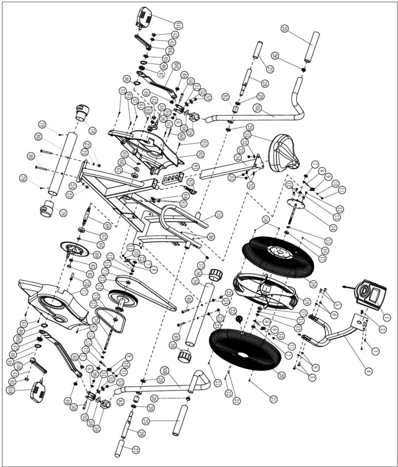
Table of Contents Safety Notice Hardware Identifier Assembly Instruction Computer Instruction Parts List Exploded Diagram Warranty
Model CB1
Retain This Manual for Reference
4-1-11
OWNER'S MANUAL
natural_image
Abstract interlocking ring design with no text or symbolsINSPIRE
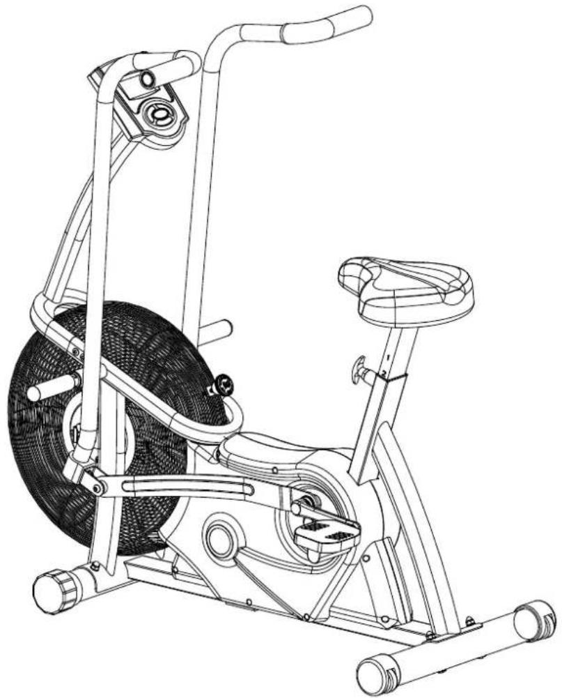
CB1 CardioBike
natural_image
Line drawing of an exercise bike with visible wheel, suspension, and balance (no text or symbols)637 S. STATE COLLEGE BLVD., FULLERTON, CA 92831
Tel: (877) 738-1729 Fax: (714) 738-1728
www.inspirefitness.net
TABLE OF CONTENTS
BEFORE YOU BEGIN 2
IMPORTANT SAFETY NOTICES ....3
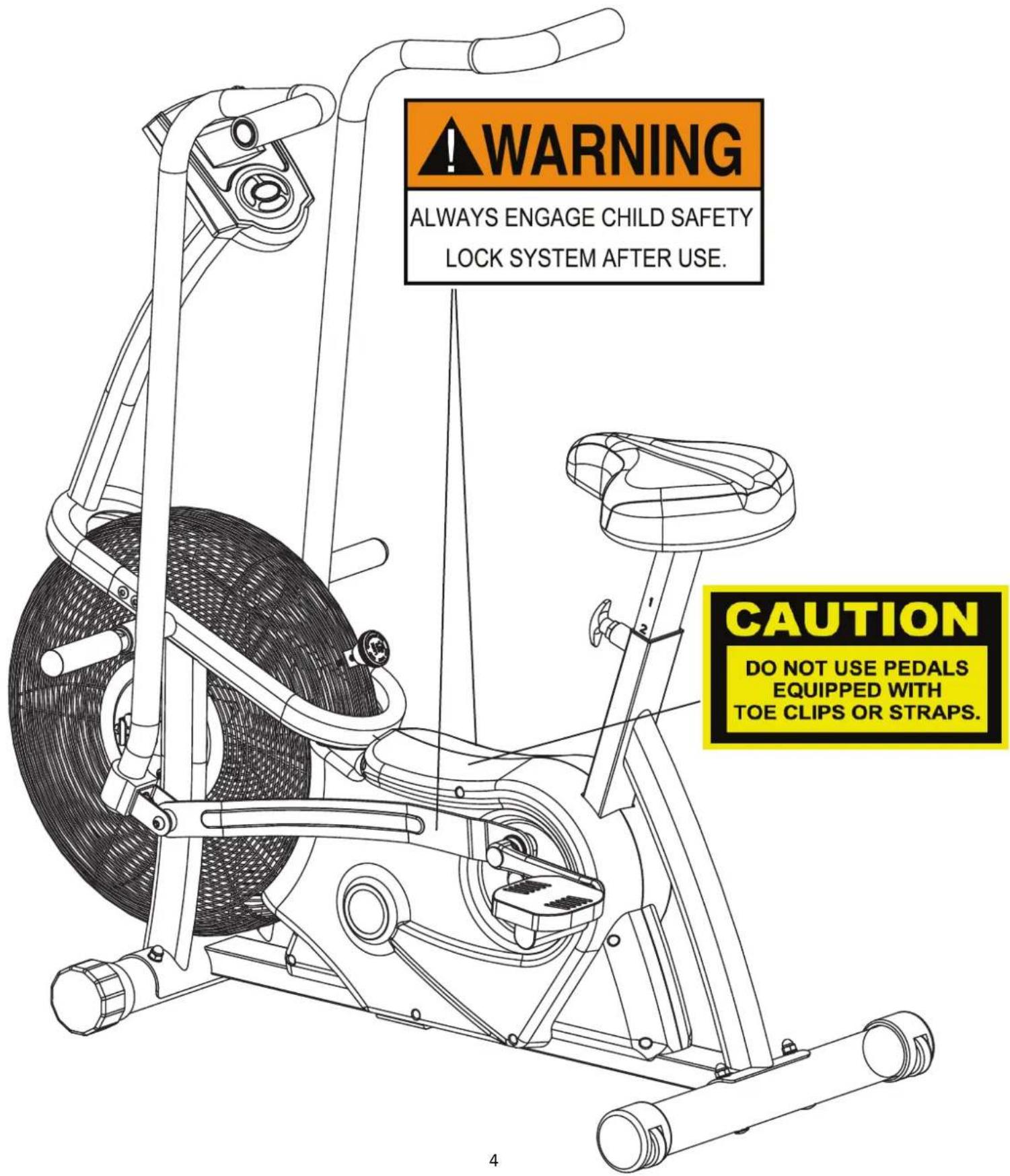
WARNING LABEL PLACEMENT....4
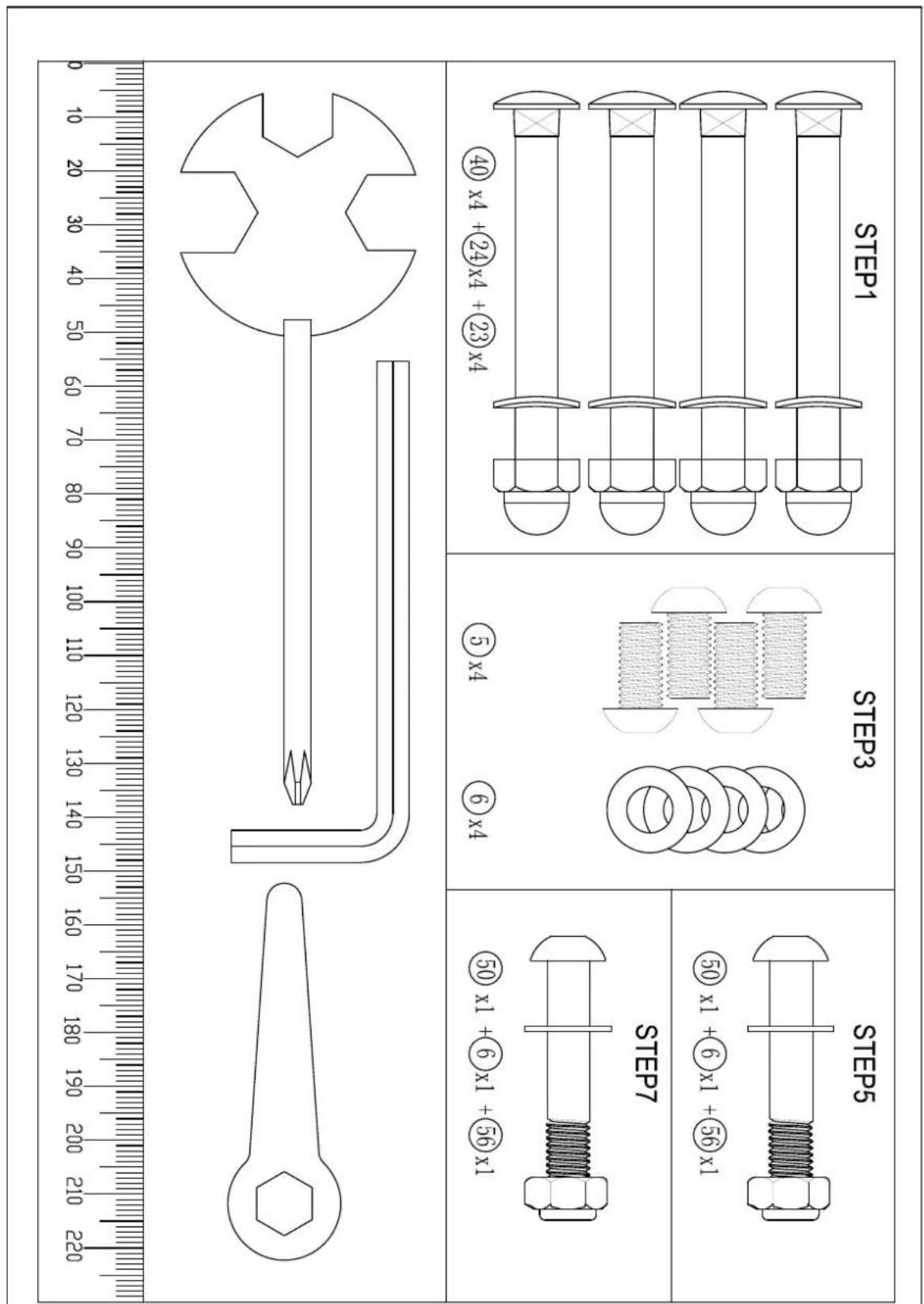
HARDWARE PACK.... 5
ASSEMBLY INSTRUCTIONS....6-16
COMPUTER OPERATION GUIDELINE....17-18
PARTS LIST....19-21
EXPLODED DIAGRAMS....22-23
WARRANTY....24
BEFORE YOU BEGIN
Thank you for selecting the INSPIRE CB1. For your safety and benefit, read this manual carefully before using the machine. As a manufacturer, we are committed to providing you complete customer satisfaction. If you have any questions, or find there are missing or damaged parts, please call our TOLL FREE customer service number. Our Customer Service Agents will provide immediate assistance to you.
Toll-Free Customer Service Number 1-877-738-1729
Mon. - Fri. 8 a.m. - 5 p.m. PST
www.inspirefitness.net
IMPORTANT SAFETY NOTICE
PRECAUTIONS
This exercise machine is built for optimum safety. However, certain precautions apply whenever you operate a piece of exercise equipment. Be sure to read the entire manual before you assemble or operate your machine. In particular, note the following safety precautions:
- Keep children and pets away from the machine at all times. DO NOT leave children unattended in the same room with the machine. The linkages on this machine can cause serious injury if used improperly.
- Never place your hands or feet in the path of the linkages because injury may occur to you or damage may occur to the equipment. Never allow children to come near or approach the moving linkages while in use.
- Always engage the CHILD SAFETY LOCK after use.
- If the user experiences dizziness, nausea, chest pain, or any other abnormal symptoms, STOP the workout at once. CONSULT A PHYSICIAN IMMEDIATELY.
- Position the machine on a clear, leveled surface. DO NOT use the machine near water or outdoors.
- Keep hands away from all moving parts.
- Always wear appropriate workout clothing when exercising. DO NOT wear robes or other clothing that could become caught in the machine. Running or aerobic shoes are also required when using the machine.
- Use the machine only for its intended use as described in this manual. DO NOT use attachments not recommended by the manufacturer.
- Do not place any sharp object around the machine.
- Disabled persons should not use the machine without a qualified person or physician in attendance.
- Before using the machine to exercise, always do stretching exercises to properly warm up.
- Never operate the machine if the machine is not functioning properly.
- Maximum user weight 300 lbs.
CARE AND MAINTENANCE
- Keep seat slider clean
- Inspect and tighten all parts before using the machine.
- Keep objects away from the fan area. Never stick anything inside the fan grill.
- The Frame, Shrouds and Seat Pad of the machine can be cleaned using a damp cloth and mild non-abrasive detergent. DO NOT use solvents.
WARNING: BEFORE BEGINNING ANY EXERCISE PROGRAM, CONSULT YOUR PHYSICIAN. THIS IS ESPECIALLY IMPORTANT FOR INDIVIDUALS OVER THE AGE OF 35 OR PERSONS WITH PRE-EXISTING HEALTH PROBLEMS. READ ALL INSTRUCTIONS BEFORE USING ANY FITNESS EQUIPMENT. NEITHER HEALTH IN MOTION, LLC. NOR FG1, LLC. ASSUME ANY RESPONSIBILITY FOR PERSONAL INJURY OR PROPERTY DAMAGE SUSTAINED BY OR THROUGH THE USE OF THIS PRODUCT. SAVE THESE INSTRUCTIONS.
WARNING LABEL PLACEMENT
HARDWARE PACK
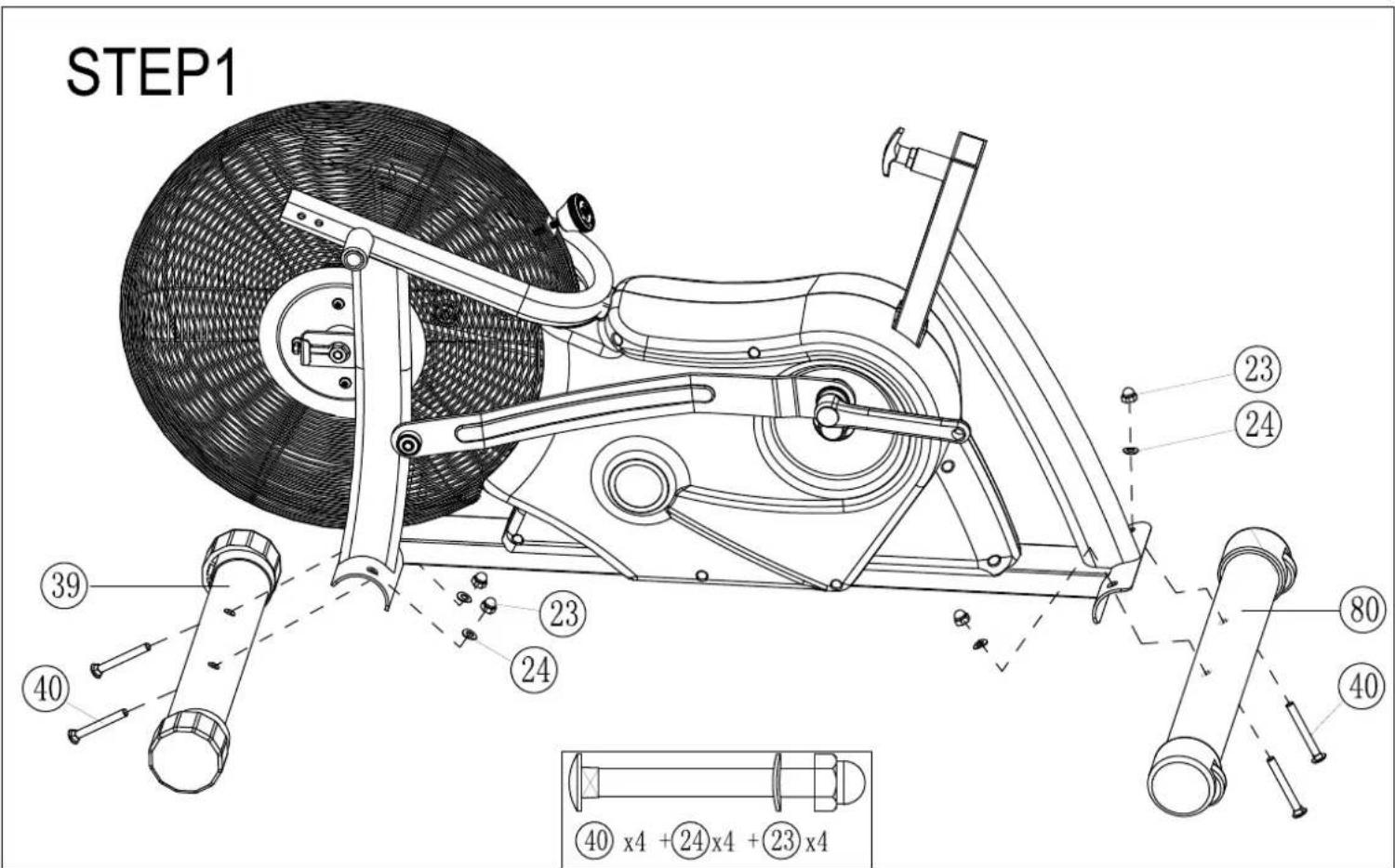
STEP 1: FRAME STABILIZER ASSEMBLY
- Attach Front Stabilizer Assembly (#39) to the Front Mounting Bracket using Qty. 2 Carriage Bolts (#40), Qty. 2 Flat Washers (#24) and Qty. 2 Acorn Nuts (#23).
- Attach Rear Stabilizer Assembly (#39) to the Rear Mounting Bracket using Qty. 2 Carriage Bolts (#40), Qty. 2 Flat Washers (#24) and Qty. 2 Acorn Nuts (#23). Ensure the roller wheels are facing backwards.
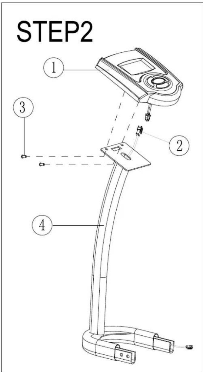
STEP 2: CONSOLE MAST ASSEMBLY
- Connect wire (#2) to the console (#1). Push connection through console mast opening so that console sits flat on console mounting plate.
- Secure Console (#1) to Console Mast (#4) using qty. 2 screws (#3).
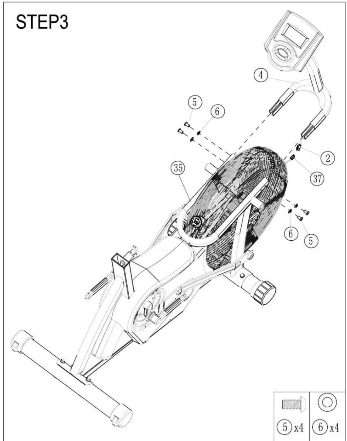
STEP 3 CONSOLE ASSEMBLY
- Connect the console wire (#2) to main frame wire (#37) then attach console mast (#4) to main frame (#35) using qty. 4 button-head screws (#5) and qty. 4 washers (#6).
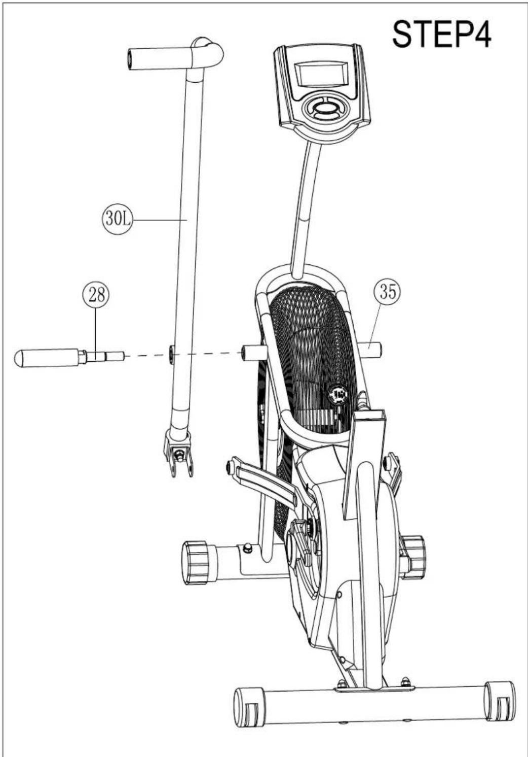
STEP 4: LEFT SWING ARM
- Slide front pivot axle (#28) through the Left Swing Arm Assembly (#30L) and screw into main frame (#35). NOTE: The Left Swing Arm bearing assembly contains a spacer between both bearings which may prevent the pivot axle from passing through smoothly. To pass the pivot axle through, place your finger in the bearing hole and center the spacer.
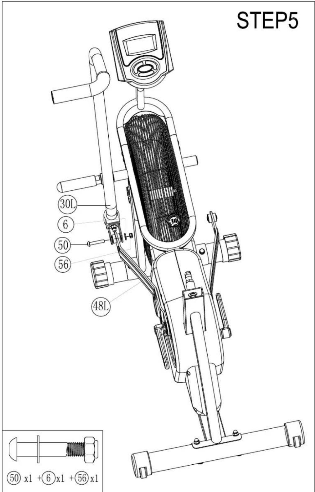
STEP 5: LEFT CONNECTING LINK
- Attach Left Swing Arm Assembly (#30L) at bottom to Connecting Link (#48L) using qty. 1 bolt (#50), qty. washer (#6) and qty. 1 nut (#56).
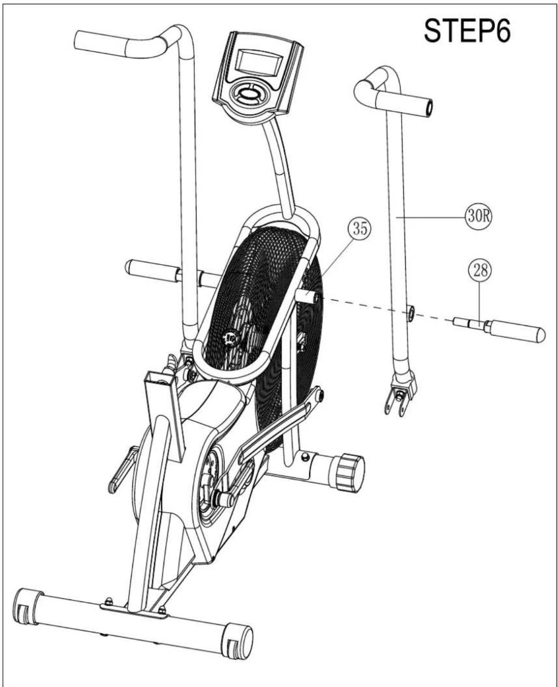
STEP 6: RIGHT SWING ARM
- Slide Front Pivot Axle (#28) through the Right Swing Arm Assembly (#30R) and screw into main frame (#35). NOTE: The Left Swing Arm bearing assembly contains a spacer between both bearings which may prevent the pivot axle from passing through smoothly. To pass the pivot axle through, place your finger in the bearing hole and center the spacer.
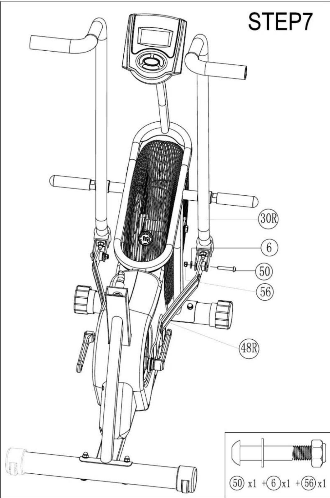
STEP 7: RIGHT CONNECTING LINK
- Attach Right Swing Arm Assembly (#30R) at bottom to Connecting Link crank (#48R) using qty. 1 bolt (#50), qty. 1 washer (#6) and qty. nut (#56).
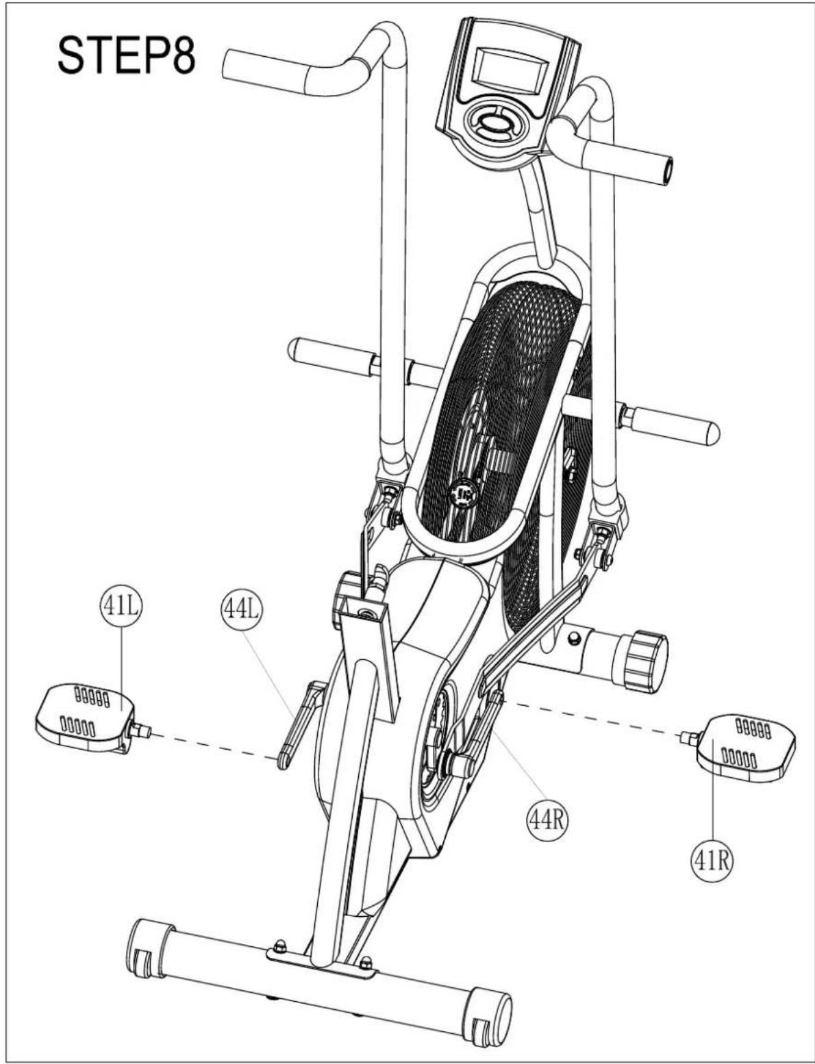
STEP 8 PEDALS
- Screw Left Pedal (#41L) onto Left Crank (#44L).
NOTE: The Left Pedal has and "L" sticker and is a LEFT HANDED thread. Turn COUNTER-CLOCKWISE to tighten.
- Screw Right Pedal (#41R) to Right Crank (#44R).
STEP 9
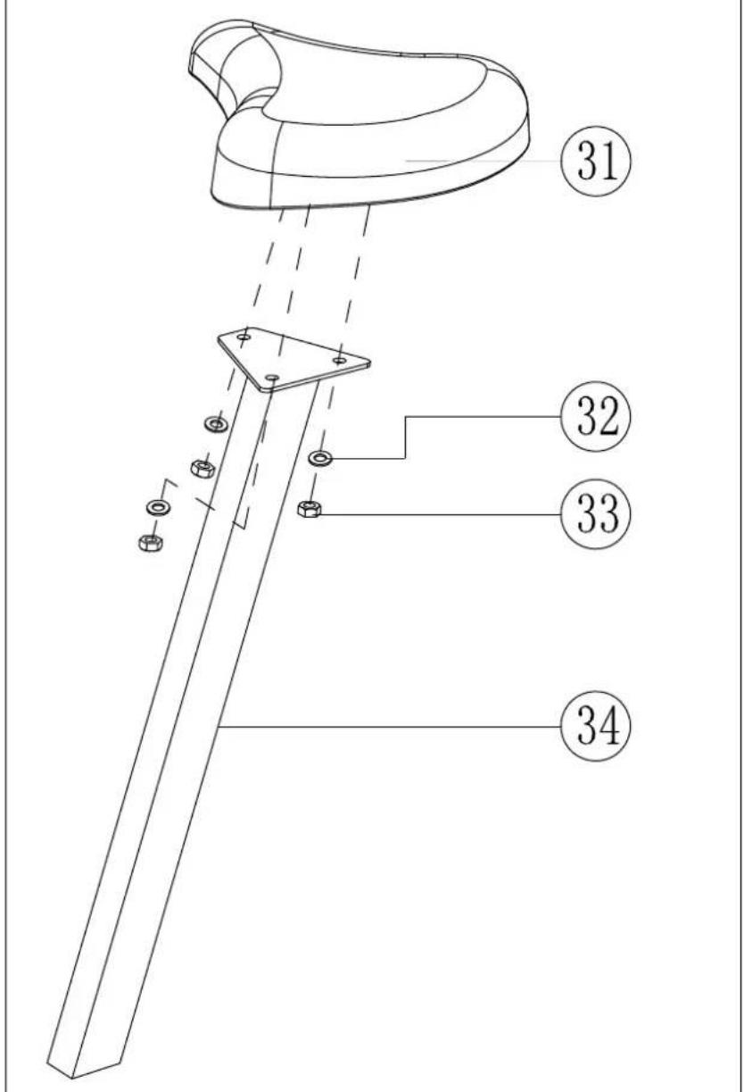
STEP 9: SEAT POST
- Attach Seat (#31) to Seat Mast (#34) using qty. 3 washers (#32) and qty. 3 nuts (#33).
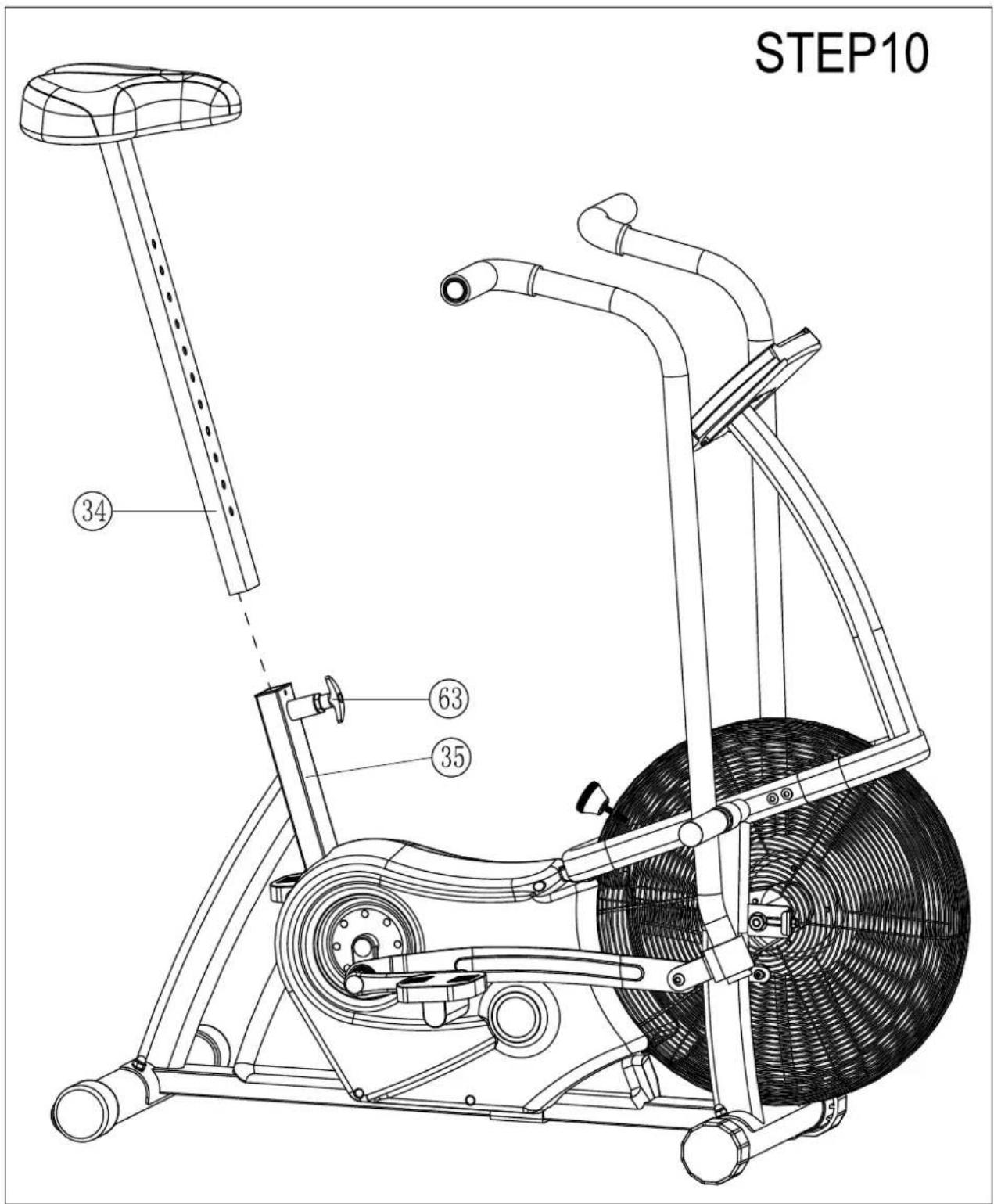
STEP 10: SEAT POST ASSEMBLY
- Slide Seat Mast (#34) into Main Frame (#35). Insert the Adjustment Knob (#63).
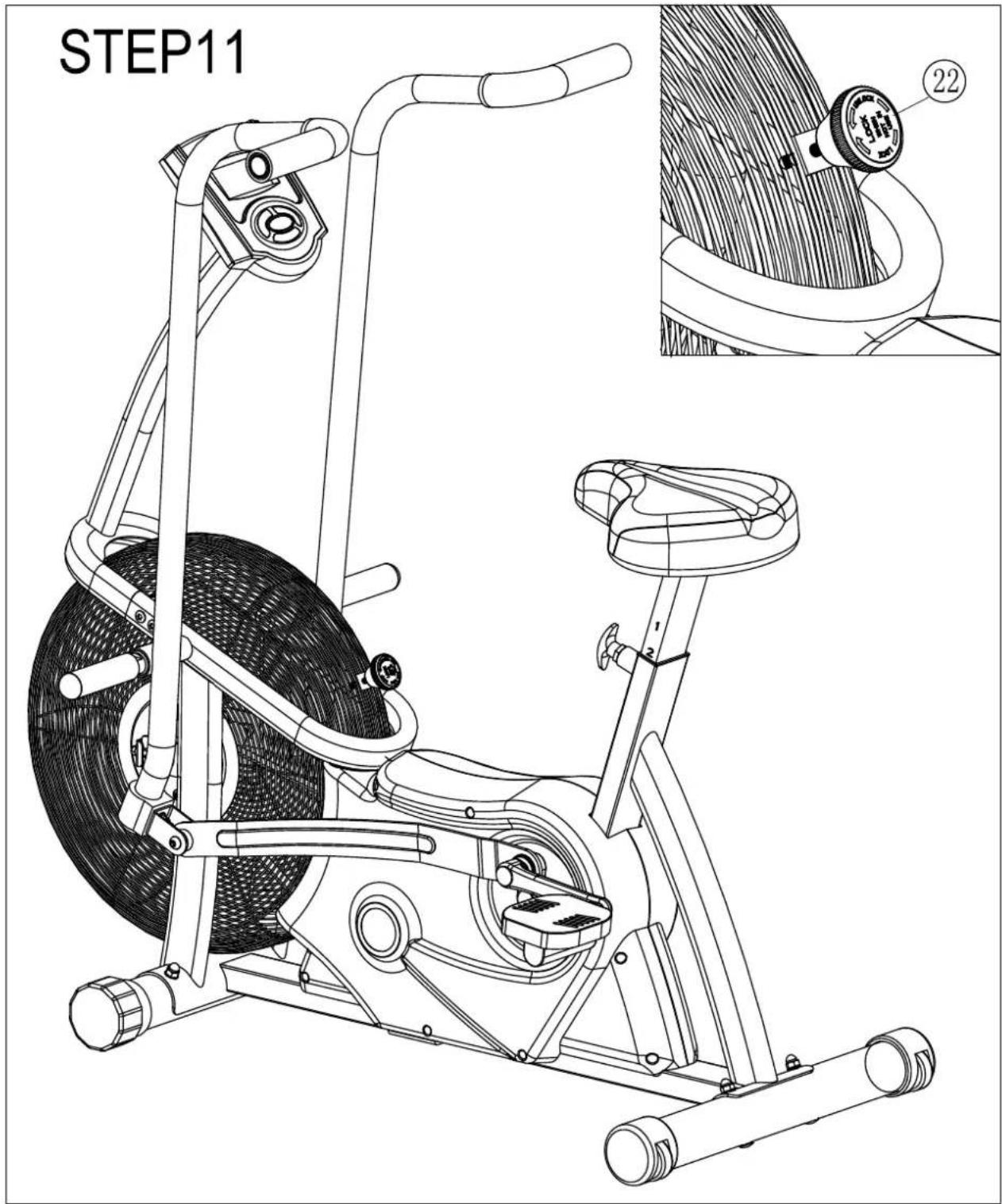
STEP 11: CHILD SAFETY KNOB
- Screw in the Child Safety Knob (#22) as shown.
IMPORTANT!
Always engage the Child Safety Knob (#22) when not using the unit. Failure to do so poses a danger to children.
COMPUTER OPERATION
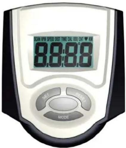
FUNCTION BUTTONS
MODE
- Press to display different values on LCD screen. LCD can display SPEED, DISTANCE, SCAN (Auto), TIME, CALORIES, ODOMETER.
- Press and hold for 2 seconds to reset all values to zero (except ODOMETER). (When user replaces the batteries, all the values will reset to ZERO automatically.)
SET
- Set a target value for TIME, DISTANCE or CAL. When you start pedaling the target value will begin counting down to zero. NOTE: When setting a target you cannot be pedaling or computer will not set target.
- Press and hold for 2 seconds to speed up the increment.
RESET
- Press to reset value to zero when setting target value. Press and hold the RESET button to reset the computer and set the target.
- Press and hold for 2 seconds to restart the computer.
(When the user replace batteries, all the values will reset to ZERO automatically.)
1. Battery Installation
Install 2 AA 1.5V batteries in the battery case on the back of monitor.
(Whenever the batteries are removed, all the values will be reset to zero.)
2. Auto On/Off
When the user starts to pedal, the display will start automatically. After pedaling has stopped for over 256 sec, the display will turn off, but the value of odometer will be stored. When the user starts pedaling again, the odometer will continue to count incrementally.
3. Auto Scan
Press the MODE button until "SCAN" is displayed in the UPPER LEFT corner of the LCD. SCAN function will display all values for TIME-CAL-ODOMETER-SPEED-DISTANCE. Each value will display for 6 seconds.
4. Speed
Shows the current training speed (MPH).
5. Distance
Accumulates the total distance from 0.0 up to 999.9 Miles. The user may preset a target distance by pressing SET button when DIST is displayed (Do NOT pedal when setting target). Each increment is 0.1 Miles when distance is less than 100 Miles, each increment is 1 Mile for distances between 100 and 999 miles. The unit counts down from the target to 0 when a target is set. The computer beeps when the target DISTANCE is reached
6. Time
Accumulates total workout time from 00:00 up to 99:59. The user may preset a target TIME by pressing SET button when TIME is displayed (Do NOT pedal when setting target). The unit counts down to 0 after target TIME is set. The computer beeps when target TIME is reached.
7. Calories
Accumulates calorie consumption during training from 0 up to 9999 calories. The user may also preset a calorie target before training by pressing SET when CAL is displayed (Do NOT pedal when setting target). Each incremental increase is 1 calorie until 1000, then each incremental increase will be 10 calories until 9990. When a calorie target is set, the computer counts down to 0 calories. Computer beeps when calorie target is reached.
Note : This data is a rough guide and should not be used for medical treatment or analysis.
8. Odometer
Displays the total accumulated distance from 0.0 to 999.0 Miles. User may press MODE key to display the Odometer value.
9. Reset
Press and hold for 2 seconds to reset all values to zero (except ODOMETER).
Note:
- If the computer displays abnormally, please remove and reinstall the batteries and try again.
- Battery Spec: 1.5V UM-3 or AA (2PCS).
PARTS LIST
| 1 | BC865-630-001RS | Computer | 1 | TZ-2153 |
| 2 | computer connection cable | 1 | ||
| 3 | cross recessed pan head screw | 2 | ||
| 4 | BC865-220-002 | Front post tube assembly | 1 | |
| 5 | 0113-208-158A | hex socket pan head screws | 4 | M8*15 |
| 6 | 0116-008-028 | Flat washer | 6 | 8 , black zinc plated |
| 7 | 0110-410-06 | Hex flange nut | 4 | M10*1; Zinc plated(Grade: 8.8) |
| 8 | B430-561-020 | Locking Bolt | 3 | M6*60 |
| 9 | BC12-011-92 | U shape plate | 3 | 1.5 |
| 10 | 0116-306-02 | Spring Washer | 4 | 6 |
| 11 | 0110-006-12 | Hex nut | 4 | M6 |
| 12 | 0113-106-128 | cross recessed pan head screw | 5 | M6*12, Black Zinc plated |
| 13 | 0110-010-91X | Hex thin nut | 4 | M10*1, Zinc plated |
| 14 | BC866-380-002 | Flywheel Shaft Assembly | 1 | |
| 15 | 0117-110-118 | Axle ring | 4 | 10 |
| 16 | 0110-705-009 | Nylon Nut | 3 | M5, black |
| 17 | 0171-600-01 | Bearing | 4 | 6000Z |
| 18 | BC865-560-006 | Left net cover assembly | 1 | 490*56 , Black |
| 19 | BC866-881-001 | Plastic Flywheel | 1 | 460*70 , Black |
| 20 | BC865-560-007 | Right net cover assembly | 1 | 490*56 , Black |
| 21 | 0113-105-108 | cross recessed pan head screw | 3 | M5*10, black |
| 22 | BC865-881-016 | Knob | 1 | M6*25 |
| 23 | 0110-308-008 | Acorn nut | 4 | M8 |
| 24 | 0116-608-008 | Arc shape spring ring | 4 | 8 , black zinc plated |
| 25 | BC866-861-001 | Foam Grip | 2 | 37* 30*230mm black |
| 26 | 0240-031-09 | End Cap | 2 | Fit with 31.8*1.5mm round tube, black |
| 27 | G810-821-003 | Handlebar Grip 3 | 2 | 120 (one side sealed) |
| 28 | BC866-220-004 | Handlebar main shaft | 2 | |
| 29 | 0171-690-093 | Bearing | 4 | 6903ZZ |
| 30L | BC865-320-001 | Left Handlebar Assembly | 1 | |
| 30R | BC865-320-002 | Right Handlebar Assembly | 1 | |
| 31 | BC865-400-001 | Seat | 1 | SB-31 w/o logo printing |
| 32 | Flat washer | 3 | 8 (w/ seat) | |
| 33 | Nylon Nut | 3 | M8, (w/ seat) | |
| 34 | BC865-400-001 | Seat Post assembly | 1 | |
| 35 | BC865-220-001 | Main Frame Assembly | 1 | |
| 36 | M310-881-003 | cable plug | 2 | Fit w/ 12mm hole |
| 37 | Lower connection cable(for computer) | 1 | ||
| 38 | A910-0001-017 | Front Foot Tube end cap | 2 | Fit w/ 60mm round tube |
| 39 | BC865-221-007 | Rear Foot Tube | 1 | 60 |
| 40 | 0111-408-708 | Pan head square neck bolt | 4 | M8*70 |
| 41L | BC865-341-001 | Left Pedal | 1 | |
| 41R | BC865-341-001 | Right Pedal | 1 | |
| 42 | BC12-221-41 | Cap | 4 | |
| 43 | 0110-410-01 | Hex flange nut | 4 | M10*1.25 |
| 44L | BC128-561-015 | Left Crank | 1 | 5.5"(black) |
| 44R | BC128-561-016 | Right Crank | 1 | 5.5"(black) |
| 45 | BC866-881-003 | Nylon washer | 2 | 30* 16*5 |
| 46 | C ring | 4 | for bearing | |
| 47 | BC865-561-011 | Bearing | 2 | 99502ZZ w/ 2 C-ring & slots |
| 48L | BC865-380-001 | Left side pedal arm connection plate | 1 | |
| 48R | BC865-380-002 | Right side pedal arm connection plate | 1 | |
| 49 | BC865-561-012 | Shoulder bearing | 4 | 608Z, Shoulder size: 2.5mm,5.5mm; Center hole: 8mm |
| 50 | 0113-208-458A | Hexagon socket head cap screws | 2 | M8*45, Thread length: 15mm; black zinc plated |
| 51 | 0251-610-02 | Plastic spacer | 2 | |
| 52 | 0116-210-02 | Big flat washer | 2 | |
| 53 | 0110-710-11 | Nylon nut | 2 | M10*1 |
| 54 | BE865-561-003 | Crank Connector | 1 | Black zinc plated |
| 55 | BC865-350-001 | U shape bracket | 2 | |
| 56 | 0110-708-028 | Nylon Nut | 2 | M8 |
| 57 | 0114-142-198 | Philip head tapping screw | 3 | ST4.2*19 |
| 58 | 0116-418-31 | Arc shape spring washer | 2 | 26* 17.8*0.3 |
| 59 | BC15-340-01 | Plastic Sleeve | 2 | Black |
| 60 | 0114-142-608 | Pan head tapping screw | 1 | ST4.2*60 |
| 61 | 0114-742-198 | Pan head tapping screw | 8 | ST4.2*19 |
| 62 | BC866-801-001A | Left Shroud | 1 | |
| 63 | GM851-881-010A | T shape spring knob | 1 | Red cap |
| 64 | BC770-801-011 | sensor holder | 1 | |
| 65 | 0117-120-018 | Limit ring for axle | 2 | 20 |
| 66 | 0116-421-011 | Arc Washer | 1 | 21 |
| 67 | 0200-310-53 | bearing | 2 | 6004ZZ |
| 68 | BC865-561-004 | Main Axle | 1 | 20*135 |
| 69 | B865-560-000 | Right crank chain plate assembly | 1 | |
| 70 | BC866-881-004 | Shroud sleeve | 1 | |
| 71 | BC866-801-002A | Right Shroud | 1 | |
| 72 | BC866-221-009 | U shape stopper | 1 | |
| 73 | 0140-206-432 | Belt | 1 | 1192,J6,Hutchinson |
| 74 | BC866-380-003 | Belt Wheel | 1 | |
| 75 | BC866-561-009 | Chain | 1 | Pitch: 12.7mm, 64 sections |
| 76 | BC866-561-005 | chain wheel axle | 1 | 10*144 , thread length: 23(M10*1) |
| 77 | BC12-011-72 | Locking bolt | 1 | M6 |
| 78 | B650-0001-025 | Rear Foot Tube End cap with roller | 2 | Fit w/ 60mm round tube |
| 79 | 0114-130-11 | Pan head tapping screw | 2 | ST2.9*11 |
| 80 | BC865-221-008 | Front Foot tube | 1 | 60 |
| 81 | 0242-060-32 | SLEEVE | 1 | Fit W/60*30*1.5MM&53.5*23.5*1.5MMTube |
| 82 | BC865-561-013 | Spacer sleeve | 2 | 21* 17.5*22mm |
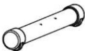
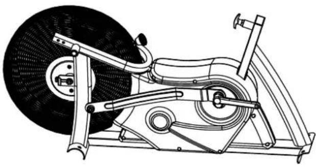 | 1 | 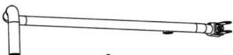 L L | 1 | ||
 | 1 | 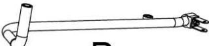 R R | 1 | ||
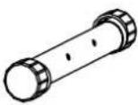 | 1 |  L L | 1 |  R R | 1 |
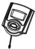 | 1 | 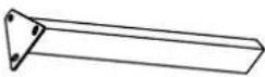 | 1 | ||
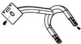 | 1 | 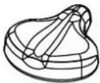 | 1 | ||
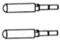 | 2 | 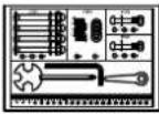 | 1 | ||
INSPIRE
Warranty
This Warranty applies to Inspire Strength products manufactured or distributed by FG1 LLC. This Product is NOT intended for LIGHT-COMMERCIAL or HEALTH CLUB use
CONSUMER USE:
10 YEAR FRAME:
Includes Main Frame and Welds
3 YEAR PARTS:
Excluding Paint and Finish (unless defective out of box)
1 YEAR LABOR
FG1, LLC. warrants that the Product you have purchased for personal, family or household use from FG1 LLC or from an authorized FG1 reseller is free from defects in materials or workmanship under normal use during the warranty period. Your sales receipt, showing the date of purchase of the Product, is your proof of the date of purchase. This warranty extends only to you, the original purchaser. It is not transferable to anyone who subsequently purchases the Product from you. It excludes expendable parts such as paint and finish. This Warranty becomes VALID ONLY if the Product is assembled / installed according to the instructions / directions included with the Product.
Replacement and repair of parts.
During the warranty period FG1 will, at no additional charge, repair or replace the Product if it becomes defective, malfunctions, or otherwise fails to conform with this Warranty under normal personal, family, or household use. In repairing the product FG1 may replace defective parts with, at the option of FG1, serviceable used parts that are equivalent to new parts in performance, or new parts. All exchanged parts and Products replaced under this warranty will become the property of FG1. FG1 reserves the right to change manufacturers and or specification of any part to cover any existing warranty.
Service procedures.
To obtain warranty parts, you must return the parts to FG1 or an authorized FG1 retailer in its original container (or equivalent). You must pre-pay any shipping charges, taxes, or any other charges associated with transportation of the product. In addition, you are responsible for insuring any product shipped or returned. You assume the risk of loss during shipment. You must present FG1 with proof-of-purchase documents (including the date of purchase, Model, and Serial Number). Any evidence of alteration, erasing or forgery of proof-of-purchase documents will be cause to void this Warranty.
To register your warranty online visit www.inspirefitness.net
Conditions and Exceptions.
This Warranty does not extend to any Product not purchased from FG1 LLC or from an authorized FG1 reseller. This Warranty does not extend to any Product that has been damaged or rendered defective; (a) as a result of accident, misuse, or abuse; (b) by the use of parts not manufactured or sold by FG1; (c) by modification of the Product; (d) as a result of service by anyone other than FG1, or an authorized FG1 warranty service provider; (e) product that has not been properly maintained (follow maintenance schedule found on product). Should any product submitted for Warranty service be found to be ineligible, an estimate of repair cost will be furnished and the repair will be made if requested by you upon FG1 receipt of payment or acceptable arrangement of payment.
Disclaimer
EXCEPT AS EXPRESSLY SET FORTII IN THIS WARRANTY FG1 MAKES NO OTHER WARRANTIES; EXPRESSED OR IMPLIED INCLUDING ANY IMPLIED WARRANTIES OF MERCHANTABILITY AND FITNESS FOR A PARTICULAR PURPOSE. FG1, LLC. EXPRESSLY DISCLAIMS ALL WARRANTIES NOT STATED IN THIS WARRANTY. ANY IMPLIED WARRANTIES THAT MAY BE IMPOSED BY LAW ARE LIMITED TO THE TERMS OF THIS WARRANTY. NEITHER FG1 NOR ANY OF ITS AFFILIATES SHALL BE RESPONSIBLE FOR INCIDENTAL OR CONSEQUENTIAL DAMAGES. FG1 IS NOT RESPOSIBLE FOR THE REPAIR OR REPLACEMENT OF ANY PARTS THAT FG1 DETERMINES HAVE BEEN SUBJECTED AFTER THE DATE OF MANUFACTURE TO ALTERATION, NEGLECT, ABUSE, MISUSE, NORMAL WEAR & TEAR, ACCIDENT, DAMAGE DURING TRANSIT OR INSTALLATION, FIRE, FLOOD, OR ANY ACT OF GOD. SOME STATES DO NOT ALLOW LIMITATIONS ON HOW LONG AN IMPLIED WARRANTY LASTS OR THE EXCLUSION OR LIMITATION OF INCIDENTAL OR CONSEQUENTIAL DAMAGES, SO THE ABOVE LIMITATIONS OR EXCLUSION MAY NOT APPLY TO YOU. This Warranty gives you specific legal rights and you may also have other rights that may vary from state to state. This is the only express warranty applicable to FG1's "Inspire" branded products. FG1 neither assumes nor authorizes anyone to assume for it any other express warranty.
- INSPIRE
- CB1 CardioBike
- TABLE OF CONTENTS
- BEFORE YOU BEGIN
- IMPORTANT SAFETY NOTICE
- PRECAUTIONS
- CARE AND MAINTENANCE
- WARNING LABEL PLACEMENT
- HARDWARE PACK
- STEP 1: FRAME STABILIZER ASSEMBLY
- STEP 2: CONSOLE MAST ASSEMBLY
- STEP 3 CONSOLE ASSEMBLY
- STEP 8 PEDALS
- STEP 9
- STEP 9: SEAT POST
- IMPORTANT!
- COMPUTER OPERATION
- FUNCTION BUTTONS
- MODE
- SET
- RESET
- Battery Installation
- Auto On/Off
- Auto Scan
- Speed
- Distance
- Time
- Calories
- Odometer
- Reset
- Note:
- Warranty
- CONSUMER USE:
- YEAR FRAME:
- YEAR PARTS:
- YEAR LABOR
- Replacement and repair of parts.
- Service procedures.
- Conditions and Exceptions.
- Disclaimer
Brand : INSPIRE
Model : CB1
Category : Home trainer