KL-6300 - Uncategorized JILONG - Free user manual and instructions
Find the device manual for free KL-6300 JILONG in PDF.


| Product Type | Optical Time-Domain Reflectometer (OTDR) |
| Models | KL-6300-S1, S2, S3, S4, S5, P1, P2, M, MS |
| Dimensions (W x H x D) | 232 mm x 161 mm x 70 mm |
| Weight | 1.6 kg (including battery and protectors) |
| Display | 7-inch color LCD touch screen, 1024 x 600 resolution |
| Power Supply | AC adapter 100-240V, 50/60Hz; Battery: 7.4V, 10500mAh, ≥77Wh |
| Battery Life | Up to 12 hours (new battery) |
| Maximum Dynamic Range | Up to 45 dB (SM models) |
| Event Dead Zone | 0.8 m (SM models) |
| Attenuation Dead Zone | 2.5 m (SM models) |
| Sampling Points | Up to 250,000 |
| Minimum Sampling Resolution | 0.04 m |
| Wavelength Options | 850/1300 nm (MM), 1310/1550 nm (SM), 1625 nm (PON models) |
| Built-in Modules | OPM, VFL, SLS, RJ45 network test, Wi-Fi, GPS (optional) |
| Fiber Inspection Probe (FIP) | Optional, 400X magnification, USB interface |
| Data Storage | Internal: ≥10,000 traces; External: USB memory |
| Languages | English, Spanish, Chinese, Portuguese, French, Russian, Thai, Korean |
| Operating Temperature | -10°C to 50°C (0°C to 40°C with AC adapter) |
| Storage Temperature | -20°C to 60°C |
| Maintenance | Clean with dry soft cloth; avoid water and solvents; store in dry environment |
| Safety | Laser class 1M/1 (SLS), class 3R (VFL); do not look directly into ports |
| Spare Parts | AC adapter, battery pack (BTR-105R, 7.4V 10Ah), OTDR modules, protective accessories |
| Manufacturer | Nanjing Jilong Optical Communication Co., Ltd., Nanjing, China |
Frequently Asked Questions - KL-6300 JILONG
User questions about KL-6300 JILONG
0 question about this device. Answer the ones you know or ask your own.
Ask a new question about this device
Download the instructions for your Uncategorized in PDF format for free! Find your manual KL-6300 - JILONG and take your electronic device back in hand. On this page are published all the documents necessary for the use of your device. KL-6300 by JILONG.
USER MANUAL KL-6300 JILONG
• Maximum dynamic range up to 45dB
• 0.8 m event dead zone, 2.5 m attenuation dead zone
• Intelligent link diagram, support Pass & Fail judgment
• iOLA, one-click Intelligent testing of passive PON networks
FiberMASTER OTDR
The KL-6300 offers superior performance thanks to a completely new algorithm, a large capacity battery and a 7in user-friendly screen. Ensure measurement quality and improve work efficiency, benefits include:
Full range selection
- Wide dynamic range 30-45dB
- Up to 9 OTDR models for selection
- Five optional modules to be customized
Operability
- 7-inch color LCD touch screen
- Generate PDF reports quickly
• F/P analytical judgment function - Smart map to analyze links graphically
Advanced trace analysis
- Multi-trace analysis
- Bidirectional testing
- 4-points test
Strong reliability
- Up to 12h battery life
• Minimum sampling resolution 0.04m
• Maximum sampling points 250,000
Not just OTDR
• VNC/GPS/WIFI
• OPM (Optical power meter module)
• SLS (Stabilized light source module)
• VFL (Visual fault locator module)
• RJ45 (Network Test module)
- FIP (Fiber connector end-face inspection module + analysis function)
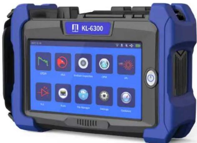
*FIP module can first perform connector end-face detection and then OTDR link testing
Full range selection
JILONG KL-6300 comes with an iLOA test function that enables complex front-line test work with less-experience, to support a variety of applications, including installation and maintenance (I&M) of mainline fiber (core network, metropolitan area network, mobile forward, mobile backhaul) and troubleshooting of access networks and FTTx. And combines industry-leading OTDR technology with OPM, VFL, SLS, network testing and fiber end inspection capabilities in one powerful handheld device.
JILONG KL-6300 OTDR Models
| Fiber type | Link type | Test application | |||||
| SM | PONArea | Installation (measurement of live fibers and dark fibers) | |||||
| Model/Description | Wavelength(nm) | ||||||
| Dynamic range(dB) | |||||||
| Access network | 1x32 | KL-6300-S1 (Entry-level model) | 1310 | 1550 | |||
| 32 | 30 | ||||||
| Acces network / Metropolitan area network | 1x64 | KL-6300-S2 (basic model) | 1310 | 1550 | |||
| 35 | 33 | ||||||
| KL-6300-P1 (3 wavelengths + live model) | 1310 | 1550 | 1625 | ||||
| 32 | 30 | 28 | |||||
| KL-6300-P2 (High dynamic range wavelengths + live model) | 1310 | 1550 | 1625 | ||||
| 38 | 36 | 34 | |||||
| Metropolitan network / Core network | 1x128 | KL-6300-S3 (Standard model) | 1310 | 1550 | |||
| 40 | 38 | ||||||
| KL-6300-S4 (High dynamic model) | 1310 | 1550 | |||||
| 42 | 40 | ||||||
| KL-6300-S5 (Super-high dynamic model) | 1310 | 1550 | |||||
| 45 | 43 | ||||||
| MM | LAN | KL-6300-M (MM model) | 850 | 1300 | |||
| 20 | 22 | ||||||
| KL-6300-MS (SM&MM model) | 850 | 1300 | + | 1310 1550 | |||
| 20 | 22 | 32 30 | |||||
KL-6300-S1/S2/S3/S4/S5
Dual wavelength module 1310/1550nm, used in fiber installations
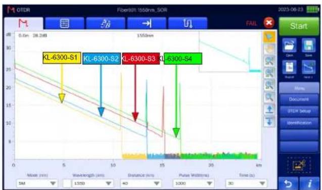
1μ s Pulse width trace
KL-6300-P1/P2
Maintenance models for real-time communication lines
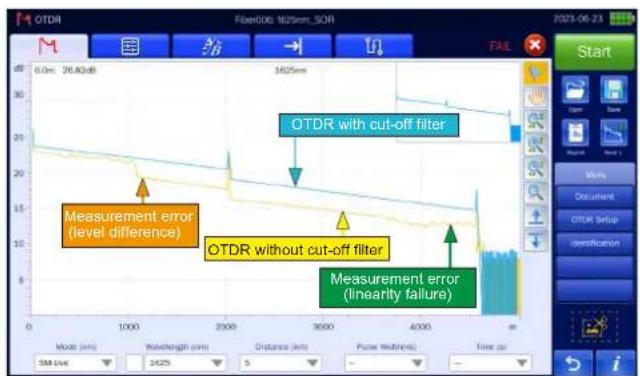
Real-time communication line trace
KL-6300-MS
KL-6300-M
SM&MM model
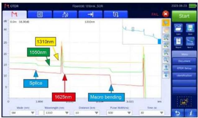
MM model
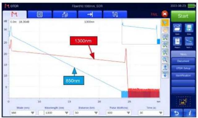
A trace with a macro bend MM fiber trace

iOLA (Hawkeye)
OTDR faces a series of challenges:

Trace is wrong

Need to analyze several traces

The same work needs to be done twice

Requires complex instrument training
To address these challenges, JILONG has developed a better way to test fiber links: iOLA (Hawkeye) is an OTDR-based application designed to simplify the OTDR testing process by eliminating the need to configure parameters, analyze and interpret multiple complex OTDR curves. It adopts advanced algorithm, can dynamically define the test parameters, and according to the measured network to determine the appropriate curve acquisition times; Multiple pulse widths at multiple wavelengths can also be correlated to locate and identify faults with very high resolution - all at the touch of a button.
Working principle
Measure the network from the site to an antenna
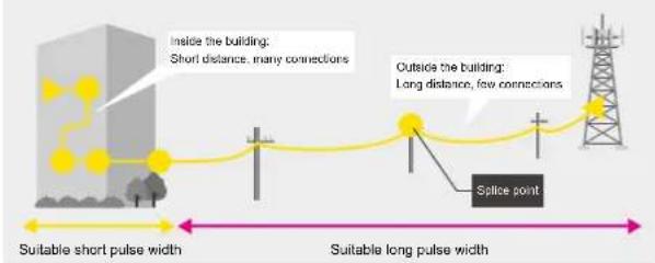

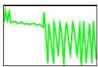
Short pulse width Mid pulse width
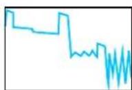
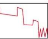
Long pulse width
flowchart
graph LR
    A["Fail"] --> B["Σ"]
    B --> C["η"]
    C --> D["η"]
    D --> E["✓"]
    E --> F["Pass"]
    style A fill:#ff0000,stroke:#333
    style B fill:#ff0000,stroke:#333
    style C fill:#ff0000,stroke:#333
    style D fill:#ff0000,stroke:#333
    style E fill:#ff0000,stroke:#333
    style F fill:#ff0000,stroke:#333

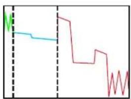

Analysis of some events of the measured trace, link the trace together

Operability
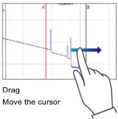
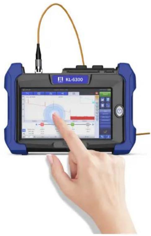
7.0 inch multi-touch capacitive touch screen
It supports new gestures to amplification. The screen capture color is clear. The interface design is simple and clear.
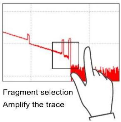
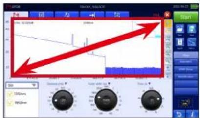
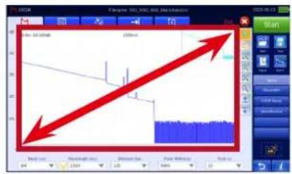
Expand the trace display area
By tapping the icon ↑ ↓ , you can enlarge the trace display area to view more detail.
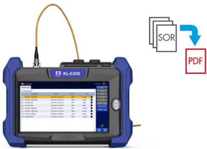
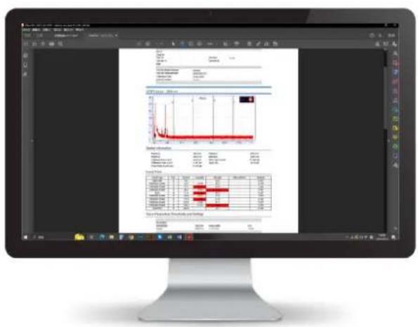
Quickly generate the PDF report
Built -in post-processing software to generate reports of PDF format.
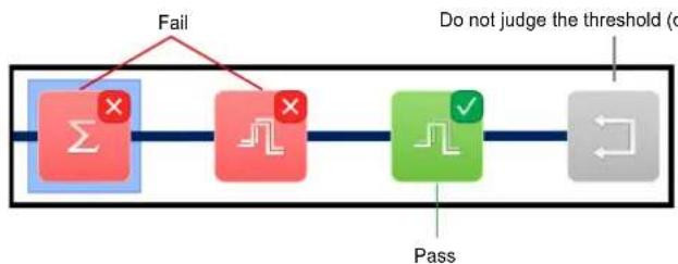
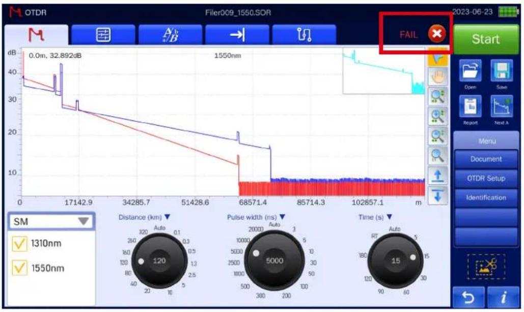
Pass & Fail analysis function
Automatically perform Pass/Fail judgments for each event based on pre-specified thresholds. The measurement results can be viewed through the result display items (As shown in the red box on the following side).
line
| Time (s) | Pulse width (ns) | | -------- | ---------------- | | 0 | 5000 | | 30 | 2500 | | 60 | 1000 | | 90 | 500 | | 120 | 200 | | 150 | 100 | | 180 | 50 | | 210 | 20 | | 240 | 10 | | 270 | 5 | | 300 | 2 | | 330 | 1 | | 360 | 0.5 | | 390 | 0.2 | | 420 | 0.1 | | 450 | 0.05 | | 480 | 0.02 | | 510 | 0.01 | | 540 | 0.005 | | 570 | 0.002 | | 600 | 0.001 | | 630 | 0.0005 | | 660 | 0.0002 | | 690 | 0.0001 | | 720 | 0.00005 | | 750 | 0.00002 | | 780 | 0.00001 | | 810 | 0.000005 | | 840 | 0.000002 | | 870 | 0.000001 | | 900 | 0.0000005 | | 930 | 0.0000002 | | 960 | 0.0000001 | | 990 | 0.00000005 | | 1020 | 0.00000002 | | 1050 | 0.00000001 | | 1080 | 0.000000005 | | 1110 | 0.000000002 | | 1140 | 0.000000001 | | 1170 | 0.0000000005 | | 1200 | 32.892 |Smart map analyze links graphically
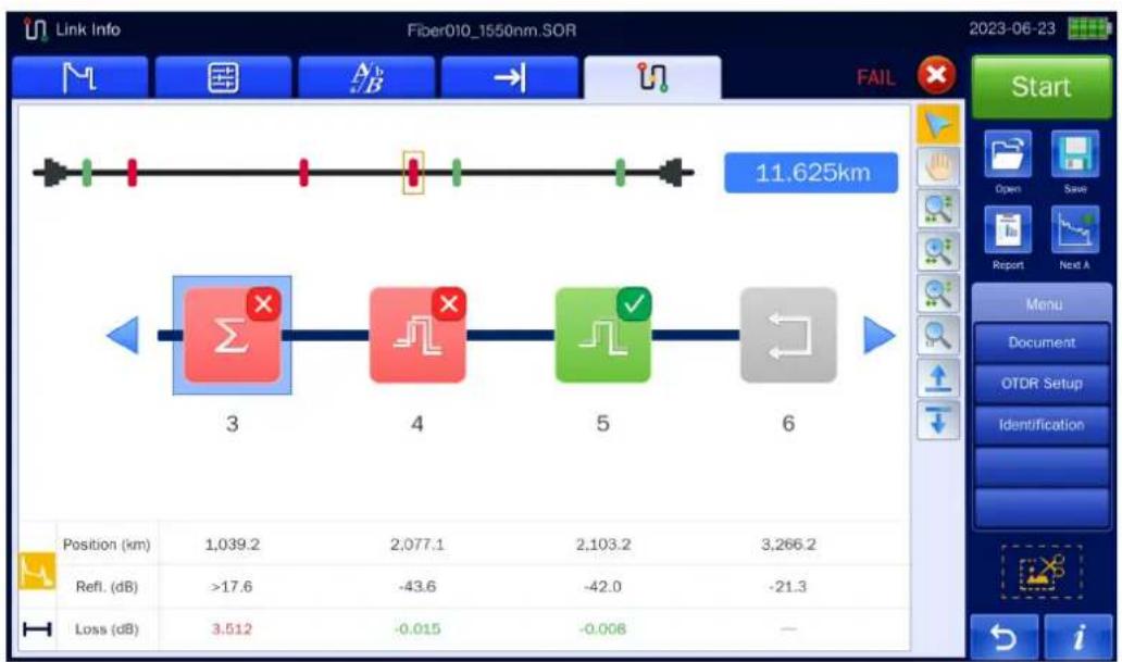
With Smart Map, users only need to press one button to execute measurement, detect network events and execute Pass&Fail judgment. It includes a simple icon view that facilitates the location and type of the event, and automatically executes the Pass&Fail judgment of each event based on the pre -specified threshold.
line
| Position (km) | 1,039.2 | 2,077.1 | 2,103.2 | 3,266.2 | | ------------- | ------- | ------- | ------- | ------- | | Refl. (dB) | >17.6 | -43.6 | -42.0 | -21.3 | | Loss (dB) | 3.512 | -0.015 | -0.008 | — |Advanced trace analysis
The OTDR master module is capable of performing advanced analysis of measured data
Multi-trace analysis
View multi -trace, can view up to 4 traces at the same time, comprehensive analysis, and the results are more accurate.
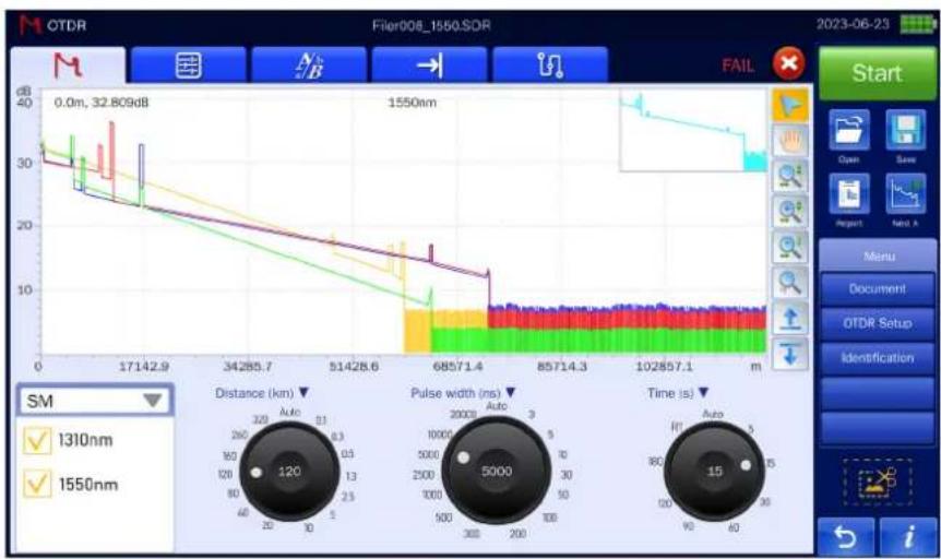
line
| Time (s) | Pulse width (ns) | Distance (km) | | -------- | ---------------- | ------------- | | 0 | 5000 | 120 | | 15 | 30 | 13 | | 30 | 250 | 13 | | 50 | 200 | 13 | | 60 | 150 | 13 | | 80 | 15 | 13 | | 100 | 15 | 13 | | 120 | 15 | 13 | | 150 | 15 | 13 | | 171 | 15 | 13 | | 285.7 | 15 | 13 | | 51428.6 | 15 | 13 | | 68571.4 | 15 | 13 | | 85714.3 | 15 | 13 | | 102857.1 | 15 | 13 | | End | - | - |Bidirectional testing
Averaging values obtained from opposite directions provides a more accurate quantification of losses. Bidirectional testing is a great way to improve test integrity in long-distance applications.
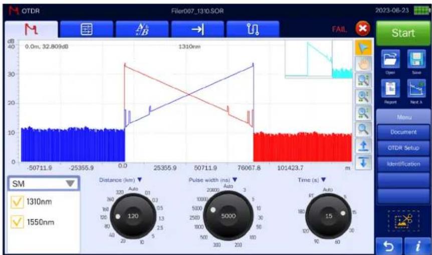
line
| Time (s) | AU (dB) | |----------|---------| | 0 | 120 | | 15 | 5000 |4-points testing
Real-time monitoring of splicing and insertion loss, less noise impact, more accurate test results.
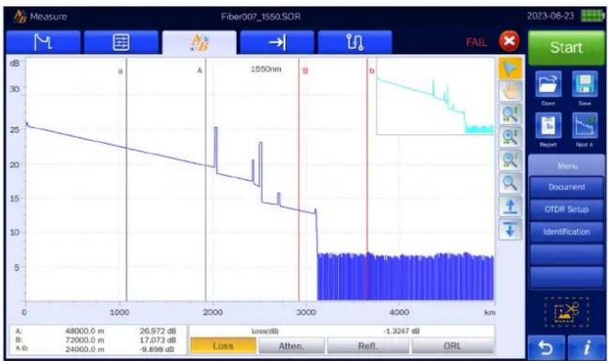
line
| A (dB) | 48000.0 m | 26.972 dB | B (dB) | 17.073 dB | A G (dB) | |--------|-----------|-----------|--------|-----------|----------| | 48000.0 | 26.972 | -1.3247 | 72000.0 | -9.898 | 24000.0 | | 72000.0 | - | - | | | | | 1550nm | - | - | | | | | | - | - | | | | | | - | - | | | | | | - | - | | | | | | - | - | | | | | | - | - | | | | | | - | - | | | | | | - | - | | | |
Strong reliability
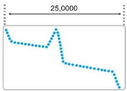
Minimum sampling resolution 0.04m
Maximum sampling points: 250,000
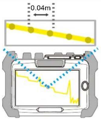
line
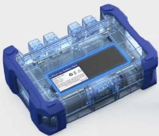
| X | Y | |---|-------| | 1 | 25,000| | 2 | 24,000| | 3 | 23,000| | 4 | 22,000| | 5 | 21,000| | 6 | 20,000| | 7 | 19,000| | 8 | 18,000| | 9 | 17,000| | 10| 16,000| | 11| 15,000| | 12| 14,000| | 13| 13,000| | 14| 12,000| | 15| 11,000| | 16| 10,000| | 17| 9,000 | | 18| 8,000 | | 19| 7,000 | | 20| 6,000 | | 21| 5,000 | | 22| 4,000 | | 23| 3,000 | | 24| 2,000 | | 25| 1,000 |Battery working time: 12 hours
natural_image
3D rendering of a transparent electronic device with blue casing and control buttons (no visible text or symbols)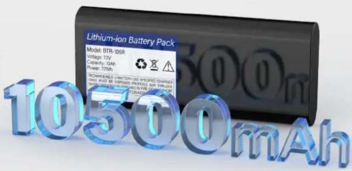
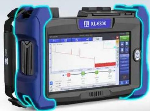
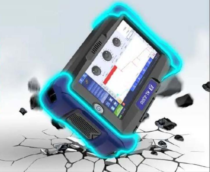
Rubber sheath design: effective shock absorption, anti-fall and anti-bump
natural_image
Illustration of a blue and black handheld device with a glowing blue overlay, partially collapsed on cracked ground (no text or symbols visible)Not just OTDR
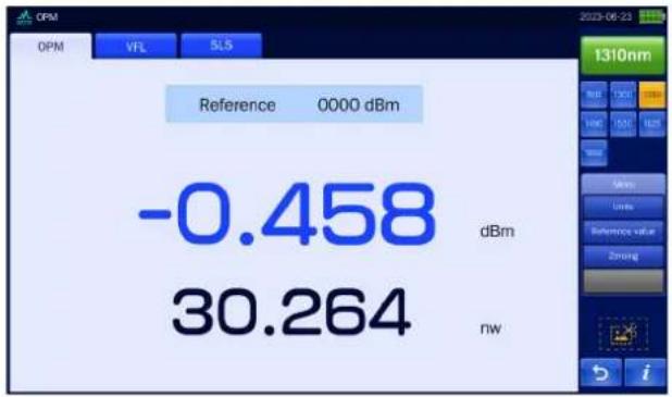
OPM module (built-in)
Used to measure absolute optical power or the relative loss of optical power through a section of fiber link
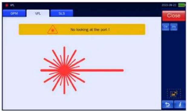
Luminous stability, strong light source, strong penetration; Two light source modes - steady on, flashing
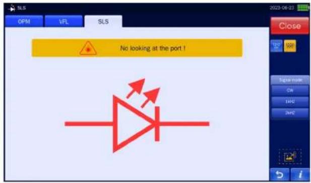
SLS module (built-in)
Output stable continuous signal, used in combination with an OPM to measure optical loss in fiber optic systems
Network test module (built-in)
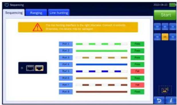
Network sequencing + Network ranging + Network hunting (optional)
Fiber connector inspection module (built-in)
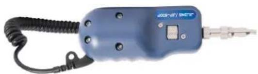
The fiber connector end-face inspection module can visualize the surface of the connector, and combine with handle probe(optional) can automatically analyze the scratches and dust on the fiber connector, save the surface image and judge the result. And offer a PDF report

natural_image
Blue handheld electrical tool with coiled cord and connector (no visible text or symbols)^a FIP module can first perform connector end-face detection and then OTDR link testing
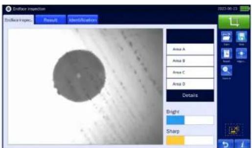

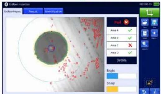
Fiber connector detection result
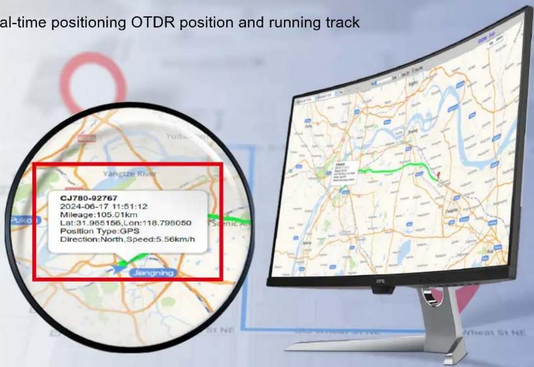
Real-time positioning OTDR position and running track
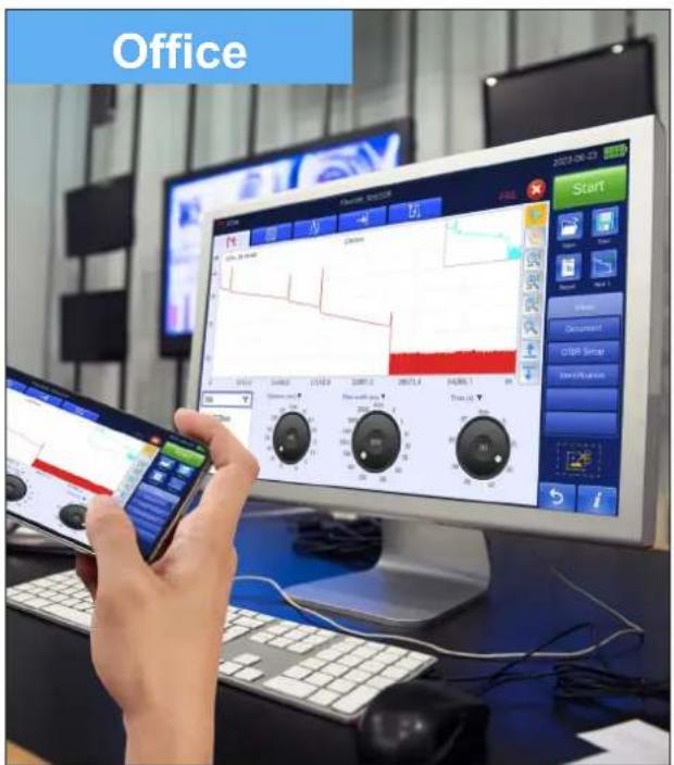
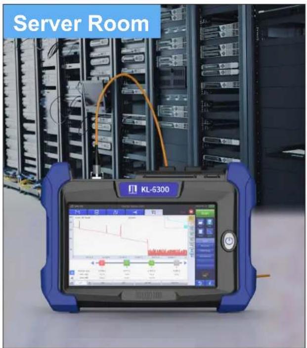
WIFI remote control (built-in)
VNC remote control function, using mobile phones or computers online remote operation OTDR easily solve the remote work, can simultaneously take into account multiple room testing, greatly improve efficiency.
PON optimization
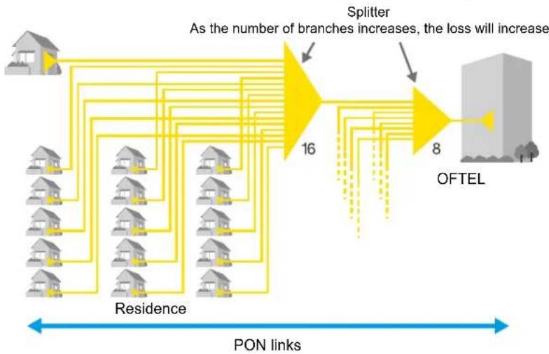
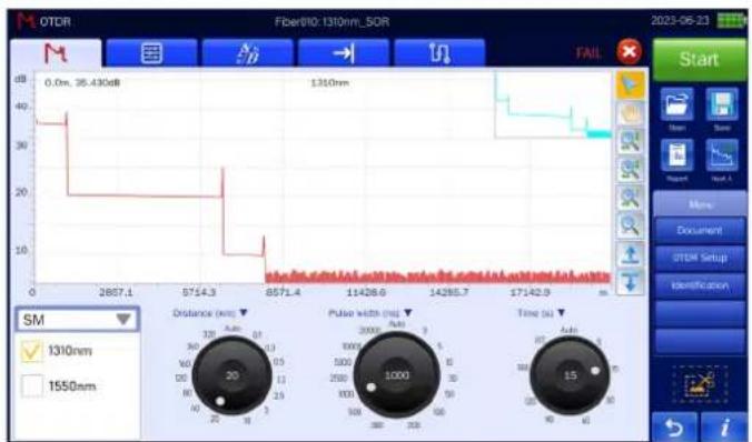
Quickly, easily and correctly measure networks with large losses, such as PON links. In PON mode, simply select the route configuration to be measured on the screen, and OTDR will automatically determine the appropriate measurement conditions and set the optimal value, even after the optical splitter caused large losses, the KL-6300 OTDR can ensure high trace quality.
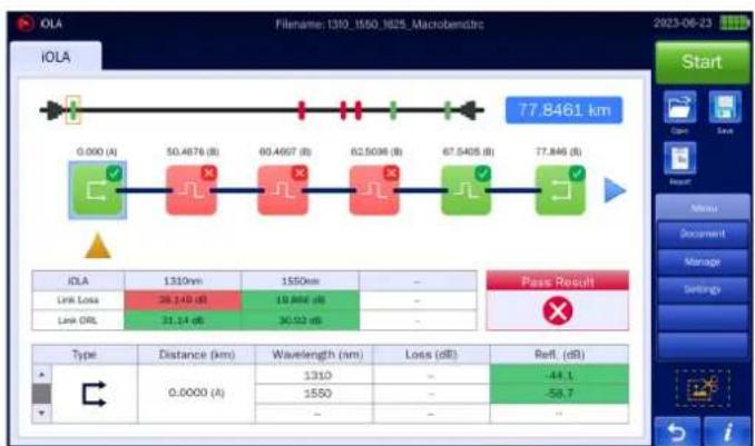
Measuring a residential PON network with two-level splitters
flowchart
graph LR
    A["House"] --> B["Residence"]
    B --> C["16 Branches"]
    C --> D["Splitter"]
    D --> E["8 Branches"]
    E --> F["OFTEL"]
    style A fill:#f9f,stroke:#333
    style F fill:#bbf,stroke:#333
    note right of D: "As the number of branches increases, the loss will increase"
    note left of B: "PON links"
    note right of F: "Residence"

Set the parameters of the splitter to be measured in PON mode
flowchart
graph LR
    A["0.000 (A)"] --> B["50.4676 (B)"]
    B --> C["60.4607 (B)"]
    C --> D["62.5098 (B)"]
    D --> E["67.5405 (B)"]
    E --> F["77.8461 (B)"]
    F --> G["77.8461 km"]
    H["IOLA"] --> I["1310nm"]
    I --> J["1550nm"]
    J --> K["..."]
    L["Link Loss"] --> M["28.140 dB"]
    N["Lock DRL"] --> O["31.14 dB"]
    P["Pass Result"] --> Q["..."]
    R["Type"] --> S["Distance (km)"]
    S --> T["Wavelength (nm)"]
    T --> U["Loss (dB)"]
    U --> V["Ref. (dB)"]
    W["0.0000 (A)"] --> X["1310"]
    X --> Y["..."]
    Z["1550"] --> AA["..."]
    AB["..."] --> AC["..."]

Ultra-high signal-to-noise ratio measurement
line
| Time (s) | Distance (ms) | Pulse width (ns) | Time (s) | | -------- | ------------- | ---------------- | -------- | | 0 | 2657.1 | 20 | 20 | | 5714.3 | 2657.1 | 10 | 10 | | 11428.6 | 2657.1 | 5 | 5 | | 14285.7 | 2657.1 | 3 | 3 | | 17142.9 | 2657.1 | 2 | 2 | | End | 2657.1 | 1 | 1 |Measuring total 1:128 splitter
Additional function
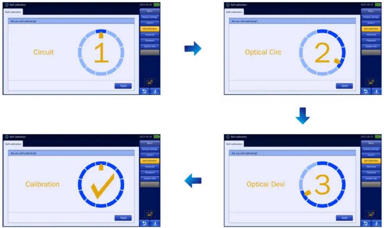
Self calibration
Shorten maintenance time and reduce maintenance costs
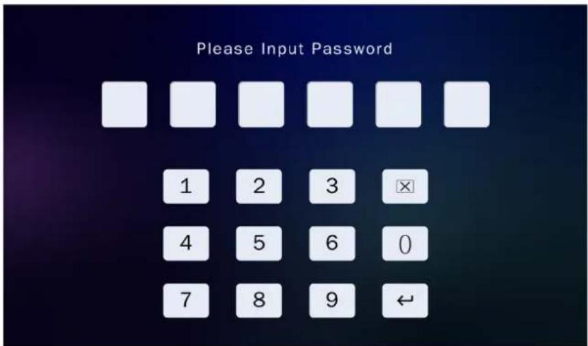
Power-on password
Acquire and use OTDR by means of leasing, paying in installments according to the agreed time and amount
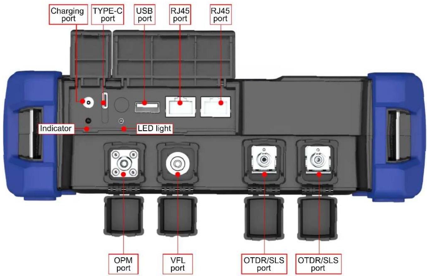
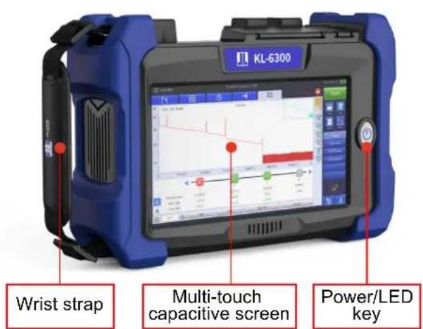
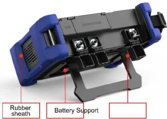
OTDR module
| Model KL-6300-S1 KL-6300-S2 KL-6300-S3 | KL-6300-S4 KL-6300-P1 KL-6300-P2 KL-6300-M KIKE3000MS5 | |||||||||
| Wavelength (nm) | 1310/1550 | 1310/1550 | 1310/1550 | 1310/1550 | 1310/1550 | PON 1310/1550/1625 (built-in filler) | 850/1300 | 850/1300+1310/1550 | ||
| Dynamic range (dB) | 32/30 | 35/33 | 40/38 | 42/40 | 45/43 | 32/30/28 | 38/36/34 | 20/22 | 20/22 32/30 | |
| Number of optical port | 1 | 1 | 1 | 1 | 1 | 2 | 2 | 1 | 2 | |
| Event dead zone★① (m) | 0.8 | 0.8 | 0.8 | 0.8 | 0.8 | 1 | 1 | 1.5 | SM≤1; MM≤1.5 | |
| Attenuation dead zone★② (m) | 3 | 3 | 2.5 | 2.5 | 2.5 | 3 | 3 | 5 | SM≤3.5; MM≤5 | |
| Multi-fiber Measurement | √ | √ | √ | |||||||
| Multi-pulse Measurement | √ | × | √ | |||||||
| Splits Measurement | Max 1:32 Max 1:64 Max 1:128 Max 1:32 Max 1:64 Max 1:32 | × | ||||||||
| Applicable fiber | SM (ITU-T G.652) | |||||||||
| Distance range (km) | 0.1, 0.3, 0.5, 1.3, 2.5, 5, 10, 20, 40, 80, 120, 160, 260, 320 | |||||||||
| Pulse width (ns) | 3.5, 10, 30, 50, 100, 200, 300, 500, 1000, 2500, 5000, 10000, 20000 | |||||||||
| Number of sampling points | Max 250000 | |||||||||
| Sampling resolution | Min 0.04m | |||||||||
| Distance measurement accuracy | ±(0.75 m + Measurement distance × 2 × 10⁻⁶ + Sampling resolution) | |||||||||
| Loss measurement accuracy | ±0.03 dB/dB | |||||||||
| Return loss measurement accuracy | ±2 dB | |||||||||
| Optical Power Meter Module (Built-in) | √ | |||||||||
| OPM | Wavelength | 800 ~ 1650nm | ||||||||
| Measure range | -70 ~ +6dBm | |||||||||
| Measure accuracy | < (±0.2dB or ±5%) | |||||||||
| Display resolution | 0.01dB | |||||||||
| Optical input port | 2.5mm Universal ferrule for FC,SC,ST/UPC | |||||||||
| Stabilized Light Source Module (Built-in) | √ | |||||||||
| SLS | Wavelength (nm) | 1310/1550 | 1310/1550/1625 | 850/1300 | 850/1300+1310/1550 | |||||
| Output power | ≥-10dBm | |||||||||
| Modulation mode | CW, 270 Hz, 1 kHz, 2 kHz | |||||||||
| Laser class | Class 1M or Class 1 | |||||||||
| Optical input port | OTDR port | |||||||||
| Visual Fault Locator Module (Built-in) | √ | |||||||||
| VFL | Wavelength (nm) | 650±10nm | ||||||||
| Output power | 10mW | |||||||||
| Modulation mode | CW, CHOP (2 Hz) | |||||||||
| Laser class | Class 3R | |||||||||
| Optical input port | 2.5 mm Universal ferrule type for FC,SC,ST | |||||||||
| Fiber Inspection Probe (Built-in) | Optional | |||||||||
| FIP | Pass / Fail | √ | ||||||||
| Magnification | 400X | |||||||||
| Resolution(um) | ≥1.0 | |||||||||
| Electrical interface | USB2.0 | |||||||||
| Optical Connector | FC/UPC,SC/UPC,ST/UPC | |||||||||
| CMOS size | 1/3 inch | |||||||||
| RJ45 Networks Test (Built-in) | √ | |||||||||
| RJ45 | Applicable cable | CAT5, CAT6 | ||||||||
| Distance of Cable Collationl | 300m | |||||||||
| Distance of emitting signal | 300m | |||||||||
| GPS Module (Built-in) | Optional | |||||||||
| GPS | Location accuracy | < 50m | ||||||||
| Real-time Monitoring | support | |||||||||
| WIFI Module (Built-in) | √ | |||||||||
| WIFI | Data transmission | √ | ||||||||
| Remote Control | √ | |||||||||
| General Specifications | |
| Link Map | √ |
| Pass/Fail judgment | √ |
| Distance unit | m, km, mile, kf |
| PC Analysis Software | √ |
| Languages | English, Español, Chinese, Português, Français, Русский,ภาษาไทย, 한국어 |
| Optical connector | FC/UPC (SC/UPC/APC、LC/UPC/APC、FC/APC Optional) |
| Display | 7-inch touch screen (Resolution: 1024 × 600) |
| Port | Charge port × 2, 12V - 2.5A & Type C |
| Operating temperature | '-10 ~ 50°C (0 ~ 40°C when AC adapter is being used. 0 to 35°C when battery is be charged) |
| Storage temperature | -20 to 60°C |
| Altitude | 4000 m |
| Humidity | 0 to 90% RH (20 to 90% with 739874 AC adapter, non-condensing) |
| Power requirements | 100 - 240V AC, 50/60Hz (AC adapter) |
| Battery | 7.4V,10500mAh,≥77Wh |
| LED Light illumination | >15000mcd |
| Operating time★(3) | 12 hours |
| Data storage | Internal storage: ≥10000 traces, External storage: USB memory |
| Dimensions | 232 mm (W) × 161 mm (H) × 70 mm (D) |
| Weight | 1.6 kg (including internal battery and protectors, excluding OTDR unit and options) |
Notes:
★①. Minimum pulse width, return loss: ≥55 dB (≥40 dB for 850/1300 nm), group refractive index: 1.5, the unsaturated peak level <1.5dB.
★②. Minimum pulse width, group refractive index: 1.5, the backscatter level is >0.5dB of the normal level. For SMF, at 1310nm, return loss: ≥55dB. For MMF, at 850nm, return loss: ≥40dB.
★③. New Battery
All specifications valid at 23^ ± 2^ ( 73.4^ ± 3.6^ ) unless otherwise specified.
Contact us
Nanjing Jilong Optical Communication Co., Ltd
Add: No. 8, Huyue East Road, Longchi Street, Liuhe District, Nanjing, China
Web: www.JILONGOT.com
Mail: info@jilongot.com
TEL: +86 400 883 6695

Focus on official website for more
- FiberMASTER OTDR
- Full range selection
- Operability
- Advanced trace analysis
- Strong reliability
- Not just OTDR
- KL-6300-S1/S2/S3/S4/S5
- KL-6300-P1/P2
- KL-6300-MS
- KL-6300-M
- iOLA (Hawkeye)
- Working principle
- inch multi-touch capacitive touch screen
- Expand the trace display area
- Quickly generate the PDF report
- Pass & Fail analysis function
- Smart map analyze links graphically
- Multi-trace analysis
- Bidirectional testing
- 4-points testing
- OPM module (built-in)
- SLS module (built-in)
- Network test module (built-in)
- Fiber connector inspection module (built-in)
- WIFI remote control (built-in)
- PON optimization
- Additional function
- Self calibration
- Power-on password
- Contact us
Brand : JILONG
Model : KL-6300
Category : Uncategorized