
UFO XL - TV antenna MAJESTIC - Free user manual and instructions
Find the device manual for free UFO XL MAJESTIC in PDF.


User questions about UFO XL MAJESTIC
0 question about this device. Answer the ones you know or ask your own.
Ask a new question about this device
Download the instructions for your TV antenna in PDF format for free! Find your manual UFO XL - MAJESTIC and take your electronic device back in hand. On this page are published all the documents necessary for the use of your device. UFO XL by MAJESTIC.
USER MANUAL UFO XL MAJESTIC
Specially compatible with HDTV of various digital terrestrial signal (DVB-T, ISDB-T, DMB-T/H, ATSC) and DAB/FM radios.
The antenna is surface-treated to withstand impacts from saltwater and weather conditions
Build-in high gain and low noise amplifier, shielded for minimum interference.
Waterproof housing design made of UV resistant, injection molded ASA material with super durability.
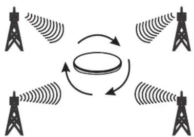
Omnidirectional antennas receive VHF, UHF, and FM signal from every point regardless of the direction you are travelling.
The best digital terrestrial TV reception solution for your boating and caravans SMD Technology and micro-electronics makes the high quality amplifier, ensure the excellent antenna performance.
Technical Specification
Frequency range: VHF: 47-230MHz UHF: 470-862MHz
Receiving range: FM/VHF/UHF
Gain: 34dB
Noise figure: 3dB
Max. output level: 110dBμV
Impedance: 75Ω
Connector: F-connectors
Power supply: DC 12V/24V
UFO XL

extreme digital performance

natural_image
Simple line drawing of a circular object with a small protrusion and arrow, no text or symbols present.Included in Packaging:
1.Antenna x 1
2. Lock Nut x1
3. Rubber Boot x1
4. F Connector x4
5. F Socket PAL Plug x1
6. 10M Coax TV Cable x1
7. Power Supply Kit x1
8. Instruction Manual x1
9. Deck Mount x1
2
3
4
5
6
8
9


- Power Supply Kit

Power Insert
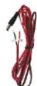
DC 12V Cable
Mounting the antenna:
Option 1. Use the deck mount for table stand. The screws included can be used to fix the antenna so it will not move.(Fig.1)

flowchart
graph LR
    A["Light Lamp with Sensor"] --> B["Switch with Sensor"]
    B --> C["Top Platform with Sensor"]
    C --> D["Bottom Platform with Sensor"]
    D --> E["Mushroom with Sensor"]
Fig.1
COAX TV CABLE CONNECTION
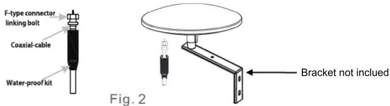
Connect the "F" male connector of the coaxial cable to the "F" female connector of the antenna, and wear the rubber boot to the end of the connected "F" connector. (Fig.2)
POWER SUPPLY CONNECTION
Option 1: Power from AC/DC power adapter.(Fig.3)
- Connect the cable from Antenna to power insert input.
- Connect the output connector of the power insert to DTV receivers or TVs.
- Connect the AC/DC adapter to the 12V/24V DC jack on the power supply unit, and plug the adapter into the power socket.
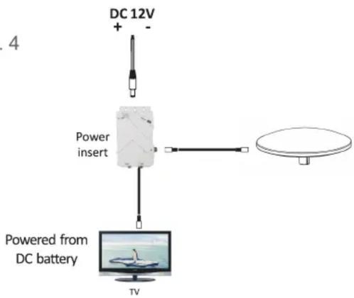
Option 2: Power from DC battery.(Fig.4)
- Connect the cable from Antenna to power insert input.
- Connect the output connector of the power insert to DTV receivers or TVs.
- Connect the DC 12V input wires to the 12V/24V DC jack on the power insert.
- Connect the other end of the wires "+" & "-" to the 12V DC system of vehicle/yacht.
Fig. 3

flowchart
graph TD
    A["AC/DC adapter 12V 150mA"] --> B["Power insert"]
    B --> C["TV"]
    D["Not included in the package"] --> B
    E["Monitor"] --> B
Fig. 4
flowchart
graph TD
    A["DC 12V"] --> B["Power insert"]
    B --> C["TV"]
    D["Satellite Dish"] --> B
    style A fill:#f9f,stroke:#333
    style B fill:#ccf,stroke:#333
    style C fill:#cfc,stroke:#333
Operation Instruction:
Note: For the best reception, please check the following conditions
- Keep the antenna away from the sources of interference: keep the antenna away from those big power consumption devices, such as air conditioner, elevator, hair dryer and microwave oven...etc.
- Install the antenna as high as possible: in digital terrestrial reception, if there are some interceptions between antenna and transmission tower, it will cause the signal loss temporarily. So if the antenna is installed as high as possible, those interceptions will be reduced.
flowchart
graph TD
    A["Tower Tower 1"] --> B["Central Circle"]
    C["Tower Tower 2"] --> B
    D["Tower Tower 3"] --> B
    B --> E["Tower Tower 4"]
    E --> F["Output Signal"]
    style B fill:#f9f,stroke:#333,stroke-width:2px
360° OMNI DIRECTION TV SIGNAL reception
Once the antenna and power supply have been installed and all cables have been properly connected, you must run a channel scan before watching TV in order to receive maximum programs. Run a channel scan as once the antenna is moved or the TV loses a channel. Now you can enjoy the TV program after you finish running a channel scan.
Brand : MAJESTIC
Model : UFO XL
Category : TV antenna