CFE536WA - Oven Chef - Free user manual and instructions
Find the device manual for free CFE536WA Chef in PDF.


| Brand | Chef |
| Model | CFE536WA |
| Product Type | Electric Oven |
| Installation | Built-in |
| Energy Source | Electric |
| Power | 3.0 kW |
| Voltage | 230 V / 50 Hz |
| Capacity | 65 L |
| Dimensions (H x W x D) | 595 x 595 x 548 mm |
| Weight | 30 kg |
| Type of Controls | Mechanical knobs and timer |
| Functions | Conventional, Grill, Fan-assisted, Defrost, Light |
| Temperature Range | 50 °C to 250 °C |
| Interior Light | Yes |
| Cleaning Type | Enamel coated interior, easy clean |
| Safety Features | Auto shut-off, cool touch door, child lock |
| Spare Parts Availability | Yes, through Chef service centers |
| Repairability Index | 8.5 / 10 |
| Documentation | User manual available in PDF |
Frequently Asked Questions - CFE536WA Chef
User questions about CFE536WA Chef
0 question about this device. Answer the ones you know or ask your own.
Ask a new question about this device
Download the instructions for your Oven in PDF format for free! Find your manual CFE536WA - Chef and take your electronic device back in hand. On this page are published all the documents necessary for the use of your device. CFE536WA by Chef.
USER MANUAL CFE536WA Chef
natural_image
Black-and-white photo of a plated dish featuring sliced meat garnished with parsley and herbs, no visible text or symbols.The Chef in Aussie kitchens for over 70 years
CONGRATULATIONS
Congratulations and thank you for choosing your Chef upright cooker. We are sure you will find your new appliance a pleasure to use and a great asset to your cooking. Before you use the appliance, we recommend that you read through the whole user manual which provides a description of the product and its functions. For future reference, please store this booklet in a safe place.
To avoid the risks that are always present when you use a gas appliance, it is important that the appliance is installed correctly and that you read the safety instructions carefully to avoid misuse and hazards.
CONDITIONS OF USE
This appliance is intended to be used in household and similar applications such as:
- Staff kitchen areas in shops, offices and other working environments
- Farm houses
- By clients in hotels, motels and other residential type environments
- Bed and breakfast type environments.
Record model and serial number here:
Model:
Serial number: ....
The symbols you will see in this booklet have these meanings:

warning
This symbol indicates information concerning your personal safety

caution
This symbol indicates information on how to avoid damaging the appliance

tips and information
This symbol indicates tips and information about use of the appliance

environmental tips
This symbol indicates tips and information about economical and ecological use of the appliance
Contents
Important safety instructions ....3
Operating for the first time....4
Installing your oven accessories....5
Using the gas cooker....6
Using the electric cooker....8
Using the Grill....10
General hints and tips ....10
Cleaning the cooker ....11
Getting to know your oven....13
Oven guide....14
Trouble shooting....15
Installation....17
Warranty 27

Important – check for any damage or marks
If you find the appliance is damaged or marked, you must report it within 7 days if you wish to claim for damage/ marks under the manufacturer's warranty. This does not affect your statutory rights.

Information on disposal for users
- Most of the packing materials are recyclable. Please dispose of those materials through your local recycling depot or by placing them in appropriate collection containers
- If you wish to discard this product, please contact your local authorities and ask for the correct method of disposal.
important safety instructions

To avoid an electric shock or fire
This appliance is NOT intended for use by persons (including children) with reduced physical, sensory or mental capabilitie, or lack of experience and knowledge, unless they have been given supervision or instruction concerning use of the appliance by a person responsible for their safety.
WARNING - Accessible parts may become hot during use. To avoid burns, young children should be kept away.
Young children should be supervised to ensure they do not play with this appliance.
DO NOT operate the hotplates with external timers or separate remote control system.
During use this appliance becomes hot. Care should be taken to avoid touching hot external, internal surfaces and hot elements when in use. Use oven gloves.
This appliance must NOT be used as a space heater.
Do NOT install gas models in marine craft, caravans or mobile homes because these products are not fitted with a flame safeguard on each burner.
DO NOT install an after market lid or cover over this appliance.
DO NOT spray aerosols in the vicinity of this appliance while it is in operation.
DO NOT store flammable materials in the appliance storage drawer or near this appliance.
Ensure all specified vents, openings and airspaces are not blocked
Install cooker, shelving and fittings in accordance with the Guide and Installation Instructions, to avoid accidents.
DO NOT operate the gas appliance if the smell of gas persists.
DO NOT MODIFY THIS APPLIANCE.

Grill warnings
DO NOT leave grill on unattended.
Fat left on a grill dish is a fire hazard! Keep grill clean and turn off grill immediately after use.
If gas burner does not light in 15 seconds, allow one minute for gas to clear before trying again.
Placing thick portions of food under grill can be a fire hazard.
DO NOT cover the grill dish insert with foil.

Separate grill model: Grill with door open
Grill in oven model: Grill with door closed

Oven warnings
DO NOT use oven door as a shelf.
DO NOT push down on open oven door.
If the gas oven does not light in 8 seconds, allow 1 minute for gas to clear before trying again.
DO NOT line oven with foil or place anything on the bottom of the oven while baking, as trapped heat will crack or craze the floor of the oven cavity liner.
DO NOT use poly-unsaturated oils (vegetable oils) as this type of oil can cause black spots or deposits inside the oven. This residue is very difficult to remove.

Hotplate and burner warnings
DO NOT allow pots to boil dry, as damage to hotplate (and pan) may result.
DO NOT operate without a pot, fry pan etc on hotplates.
DO NOT allow cookware to overhang hob onto adjacent bench tops, this will cause scorching to the bench top surface.
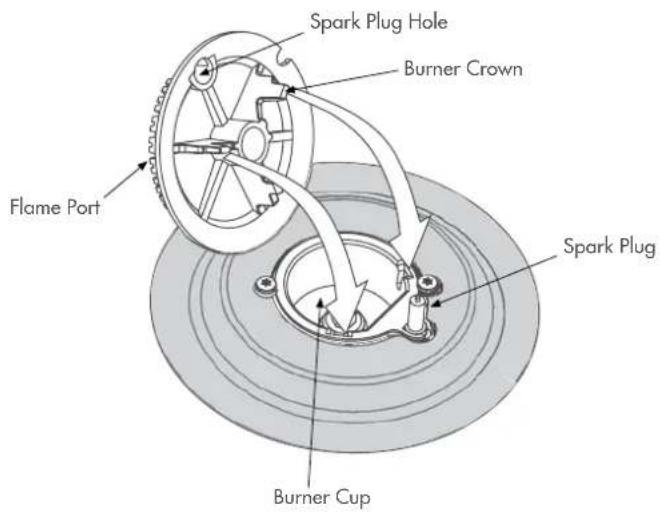
Gas models: Ensure burner caps and crowns are in their correct position.
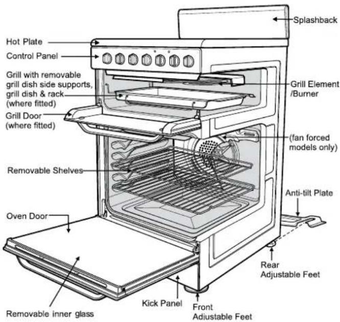
General appliance description
Electric Separate Grill Oven depicted
operating for the first time
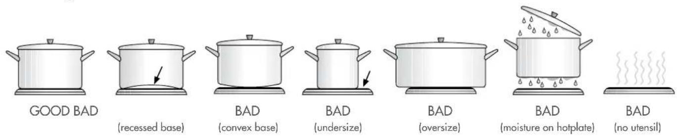
Choosing utensils for gas and electric hotplates
Refer to diagram below

Installation and service warning
- Only an authorised person must install and service this appliance (Certificate of Compliance to be retained)
• In order to avoid tipping of appliance the anti-tilt plate MUST be installed
• Appliances requiring connection to 230 – 240V MUST be earthed
• An authorised person should inspect this appliance every 5 years - This appliance must NOT be installed on a base, box or in a closed cupboard
- If the electrical supply cord is damaged, a qualified person MUST replace the cord to avoid a hazard or void your warranty
• Surrounding kitchen cabinets MUST WITHSTAND 85°C - In order to avoid a hazard the installation instructions MUST be followed.

Before operating first time
- Read all the Warning and Safety information
- Remove all internal boxes and bags from oven
- Clean out the oven interior with detergent and hot water and polish with a soft cloth. DO NOT close oven door until the oven is completely dry
- New appliances can have an odour during first operation. It is recommended to 'run in' the oven before you cook. Run the oven at 180°C for 2 – 4 hours and ensure that the room is well ventilated
- If your appliance is fitted with solid hotplates, turn heat setting to high for 3 minutes to fully harden the hotplate coating.
installing your oven accessories
Fitting oven shelves
- Ensure shelf orientation is correct (refer to diagram below)
- Slide oven shelves onto oven supports (side runners) at an angle until raised back of shelf is past the stop on oven supports (side runners)
- Lower front of shelf and push in until stop is reached
- To remove oven shelves, withdraw to the stop and raise the front of shelf to clear the stop.

Oven shelf location
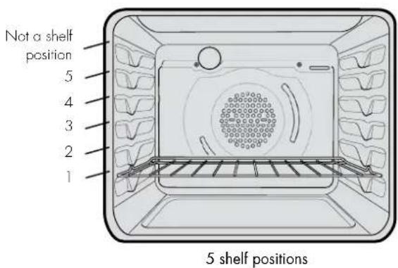
NOTE: the top ledge is not a shelf position. There are no stops for shelf withdrawal.
Fitting the grill dish
Separate Grill: Ensure rear of the dish is engaged with the side support before sliding backwards. To remove, simply pull forwards and upwards.
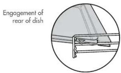
Grill in Oven: see Fitting Oven Shelves
The grill dish with wire insert can be used in any of the two upper height positions (shelf positions 4 and 5) between the runners. NOTE: You must remove the grill dish when baking in the oven.
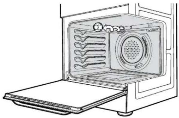
Replacing the oven light
! warning
Ensure the appliance is switched off at power supply (not just the control knobs) before replacing the light globe to avoid possibility of electric shock.
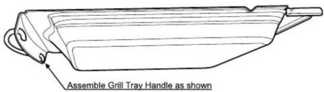
natural_image
Line drawing of an open microwave oven with ventilation slots and a door, showing internal structure without any text or symbols.Assemble grill tray handle
using the gas cooker
Gas oven features and descriptions
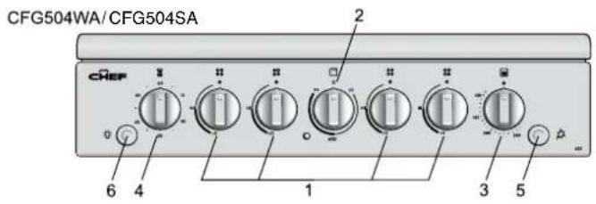
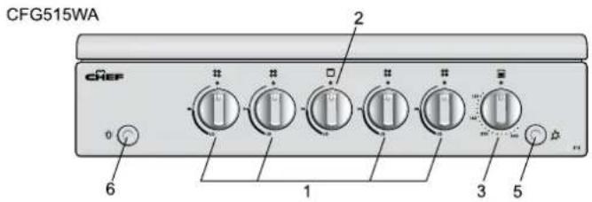
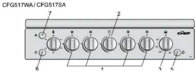
- Burner Control Knob – sets burner temperature
- Grill Control Knob – sets grilling temperature
- Oven Control Knob - sets oven temperature
- Timer 60 Minute (where fitted) – sets reminder time. When timer returns to zero, timer gives a short ring NOTE: for any time below 15 minutes, turn knob past 15 minutes, then back to required time setting
- Manual Grill or Oven Igniter – ignites grill burner or oven burner when appropriate control knobs are set
- Light Switch (where fitted) - turns oven light on/off
- Fan Switch – turns oven fan on/off.
Gas oven conventional baking
The heat comes from the bottom oven burner. The temperature at the centre of oven is the same temperature set on the control knob. When oven is used on this mode, shelf position is important, (refer to 'Oven Guide'). As hot air naturally rises, the upper half of the oven will be approximately 10°C higher and the lower half approximately 10°C cooler than the set temperature.
For best results from your gas oven use dark coloured trays and baking dishes on a single shelf. Refer to 'General Hints and Tips' section for more information.
For best baking results preheat oven for 30 minutes
Gas oven fan forced baking
Fan Forced baking generally requires lower temperatures than conventional baking. Most recipe books, unless stated, are for conventional oven temperatures. It is recommended when using the fan forced mode to reduce the oven temperature by 10°C. In a fan forced gas oven the heat comes from the bottom burner. Hot air is distributed by an electrically operated fan located behind the rear wall of the compartment, providing an even temperature on all shelf levels. This means batches of the same food can be baked using multiple shelf positions simultaneously.
Fan Forced operation can be used for single shelf baking with equal success.
For best baking results preheat oven for 30 minutes before turning on the fan.
using the gas cooker
Gas hotplate
Ensure burner caps, crowns and trivets are properly assembled. For wok ONLY use the trivet and burner dedicated for wok cooking.
Gas oven burner flame
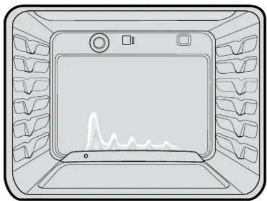
From a cold start the oven burner flame will be higher on the left hand-side. This does not affect cooking results.
natural_image
Line drawing of a microwave oven with rack-mounted dish (no text or symbols)Lighting gas hotplate, grill and oven
Hotplate Ignition - (Electronic)
Turn appropriate Burner Control Knob onto maximum and at the same time press the Electronic Igniter Switch.
Hotplate Ignition - (Manual)
Need to be ignited by hand igniters (not supplied).
Grill Ignition – Electronic
Turn Grill Control Knob onto maximum and at the same time press Electronic Igniter Switch.
Grill Ignition - Manual (Piezo)
Turn the Grill Control Knob on to Maximum and at the same time press the igniter button (several times if necessary)
It will make a loud 'clack' noise as the piezo mechanism creates a spark
Grill - in Oven
Grill is electric and is operated by control knob only.
Oven Ignition – Electronic
Push and hold Oven Control Knob onto desired temperature and at the same time press the Electronic Igniter Switch.
Hold control knob in for 15 seconds after ignition.
Oven Ignition - Manual (Piezo)
With the left hand push and hold the Oven Control Knob in and turn it a quarter of the way anti-clockwise. Keep the oven Control Knob pushed in firmly and at the same time push the Oven Piezo Ignition button on the right hand side of the control panel (several times if necessary). It will make a loud 'clack' noise as the piezo mechanism creates a spark.
Hold control knob in for 15 seconds after ignition.
IMPORTANT: If hotplates, grill or oven do not light within 15 seconds, allow 1 minute for gas to clear before trying again.
using the electric cooker
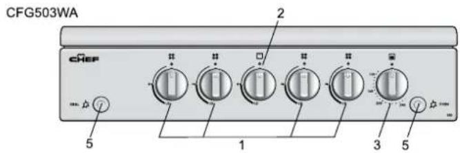
Electric features and descriptions
Grill in Oven Models
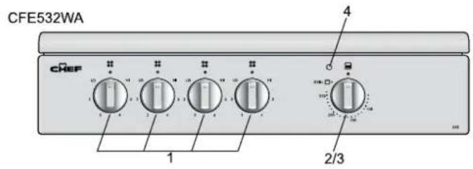
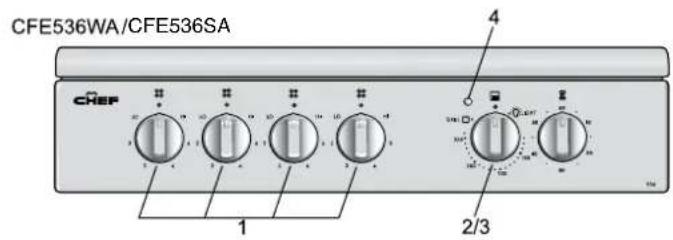
Separate Grill Models
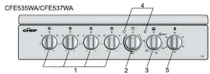
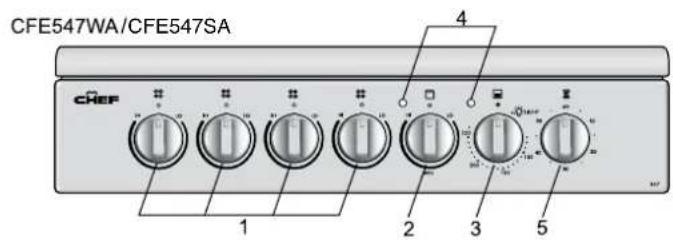
- Solid/Ceramic Hotplate Control Knob - sets hotplate temperature
- Grill Control Knob – sets grilling temperature
-
Oven Control Knob - sets oven temperature
-
Grill/Oven Indicator Light(s) – Comes on when grill/ oven temperature knob is operated. Oven indicator light cycles on and off when temperature is reached
- Timer 60 Minute – (where fitted) sets reminder time.
- When timer returns to zero, timer gives a short ring.
NOTE: For any time below 15 minutes, turn knob past 15 minutes, then back to required time setting.
Solid hotplates
If present, the red dot in the centre of hotplate changes colour when heated.
When necessary to keep element looking good, apply coating of 'hot plate protection' onto solid hot plates.
Ceramic Hotplates

warning
If the surface is cracked, switch off the appliance to avoid the possibility of electric shock.
- The ceramic cooktop is made from ceramic glass, a tough, durable material that withstands heating and cooling without breaking. However, it must be noted that as it is glass, it may break, and must therefore be treated with care. Should you have any questions about the glass in your new appliance, please contact the service centre by dialling 13 13 49
• The smooth glass surface has a pattern to show where the elements under the glass are located - When a hotplate is on, the hot surface warning light will come on. After switching off, this light will continue to glow until the temperature of the hotplate drops below 60°C.

Electric oven conventional baking
Heat comes from two elements, one above and one below the food. The bottom element is hidden below the floor of the oven. As hot air rises naturally, the upper part of the oven will be approximately 10^ C higher than the set temperature and the lower part of the oven approximately 10^ C cooler.
For Grill in Oven Models, the grill dish must be removed when baking.
For best baking results, preheat oven for 30 minutes, also refer to 'General Hints and Tips'
using the electric cooker
Electric oven fan forced baking
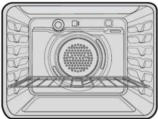
In a fan forced electric oven the heat comes from the rear oven element. Hot air is distributed by a fan behind the rear wall of the compartment, providing an even temperature on all shelf levels. This means, batches of food can be baked using multiple shelf positions simultaneously.
Fan forced operation can be used for single food baking with equal success.
Fan Forced baking generally requires lower temperatures than conventional baking. Most recipe books, unless stated, are typically for conventional oven temperatures. It is recommended that when using the fan forced mode, reduce the oven temperature by 10 degrees (refer to 'Oven Guide').
For best baking results preheat oven for 30 minutes
natural_image
Line drawing of an oven interior with grilles and a central circular vent (no text or symbols)
Using the Grill
- Separate Grill: Grill with door open. Grill dish must be fully inserted.
• Grill in oven: Grill with door closed.
Hints general
- For best baking results preheat oven for 30 minutes
- The material and finish of baking trays and dishes used will affect the way foods are baked, especially base browning.
- Enamelware, anodised aluminium, dark bakeware or non-stick interiors and coloured exteriors will assist in maintaining or reducing the baking time and increase base browning
- Ovenproof glassware or ceramics are poor conductors of heat. The shiny surface of aluminium or polished steel utensils and trays also reflects the heat rather than passing it through to the food being baked
• Always place dishes centrally on the shelf to ensure even browning - Stand casseroles dishes or similar-type dishes on suitably sized baking trays to prevent spillage onto the base of oven to make cleaning of oven easier
• DO NOT place dishes, trays or baking pans directly on the oven base as they become very hot and will crack and craze the oven liner
- Use ovenproof cookware, which will withstand temperatures of 250°C
- DO NOT use baking trays larger than 30 x 35cm (12 x 14 inches) as they will restrict the circulation of the heat and may affect cooking performance of the oven
- Use shallow casserole dishes in preference to deeper ones as this shortens cooking time in the oven
Conventional Oven
- The shelf position is critical. The temperature in centre of the oven is the temperature shown on the oven control knob. Single shelf baking gives optimal cooking results.
- DO NOT place baking trays, oven dishes or foil directly on the base of oven, as trapped heat will crack and craze the floor of the oven liner
Fan Forced
• DO NOT place baking trays and oven dishes directly against the grid covering the fan at the back of the oven
• DO NOT Place oven dishes directly on the oven base
• Make sure shelves are evenly spaced
- When baking more than one dish in fan forced oven, place dishes centrally on shelves rather than several dishes on one shelf
- When the oven is full you may need to allow a slightly longer baking time
- When using different size trays or cooking different types of food, cooking times may vary for each dish

General tips
Condensation and Steam
• Always stand back from heated oven when opening oven door to allow any build-up of steam or heat to release
- During cooking steam may be produced which can be released when opening the oven door. This is quite normal
- If there is any build-up of condensation on the oven door it is recommended that it be carefully wiped away either during or after cooking
Cleaning the cooker
Ovens and hotplates are made from steel and enamel. Do not use abrasives and harsh scourers as they may scratch the surface
Stainless Steel
- All grades of stainless steel can stain, discolour or become greasy. You must clean these areas regularly by following the procedures below if you want your appliance to look its best, perform well and have a long life
- Care must be taken when wiping exposed stainless steel edges as they can be sharp
- The front frame around the oven can be cleaned with stainless steel cleaners if it comes soiled or discoloured
• A suitable cleaner can be purchased from Electrolux Customer Care Centres
• Make sure you follow the polish or brushing lines in the steel
General
- Always clean appliance after use, especially food spillage. DO NOT use steel wool, wax polishes or caustic based commercial cleaners as these will damage your oven
- DO NOT use steam cleaners, as this may cause moisture build-up especially in the glass door
- Door Glass – DO NOT use harsh abrasive cleaners or sharp metal scrapers to clean glass since they can scratch the surface, which may result in shattering of the glass.

WARNING
Door glass is a tough and durable material designed to withstand heating and cooling without breaking. However it must be remembered that it is glass and may break, therefore must be treated with care. If you have any questions about the glass in the oven please contact the Service centre on 13 13 49.
cleaning the cooker
Oven
• Do not remove the oven door
• Make sure oven knobs are in the off position
• Clean immediately after use as a warm oven is easier to clean
- Use detergent, hot water (and household ammonia/cloudy ammonia if necessary) and a soft cloth. Dry thoroughly.
- Remove shelves when cleaning oven
- If there is a build-up of grease, place a small oven proof dish containing 14 cup (62mL) household ammonia/cloudy ammonia and 34 cup (187mL) water in the oven. Heat oven to 110 degrees and turn oven off when 110 degrees is reached. Leave overnight. The fumes will loosen stubborn grease and stains. Remove bowl, wash with hot, soapy water and dry well before closing oven door again.
Oven Shelves
- Chrome shelves: use detergent and hot water. If very dirty use a non-abrasive nylon scourer
- Enamel dishes and tray: use detergent and hot water. If very dirty a non-abrasive nylon scourer
• DO NOT clean oven parts with abrasive or caustic-type cleaners.
Oven - Grill Dish and Insert
- After every use, and while still warm, sprinkle grill insert with detergent and cover with wet paper towel as this will loosen food particles and grease
- Wash pan and grid with hot, soapy water with a little household ammonia/cloudy ammonia added. Rinse and dry before replacing in position.
Ceramic Hotplates
- Clean with detergent and hot water and polish with a soft cloth
• For harder to clean spills a blade scraper is supplied - Aluminium foil, plastic and high sugar content food can cause pitting if not removed before the hotplate has cooled.
Solid Hotplates
- Solid hotplates are fitted with stainless steel trim rings, which after initial use, change colour to light brown. This is a normal characteristic of stainless steel and will not affect the operation or performance of your hotplates
• Clean off any spillage after hot plate has cooled down - At regular intervals, clean hotplate with a nylon scouring pad and soapy water. Wipe clean then warm hotplate for 30 seconds to dry the surface
- Apply 'hot plate protector'. Set hotplate on high for 3 minutes to allow coating to harden.
Gas Burners
- Flame port blockages should be removed with a small metal cake skewer or nylon brush.
- Clean dirty spark plugs very gently with a nylon scourer. DO NOT use steel wool. DO NOT bend spark plug as it may break.
general hints and tips
Cleaning the Oven Door
Cool air circulates through the door to lower the surface temperature on the outside of the oven door.
• Do not remove the oven door
• This product has a removable inner door glass.
To remove the inner door glass for cleaning
- Open the door fully to access the hinges then rotate the "stirrups" on both hinges fully towards the door.
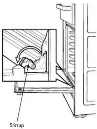
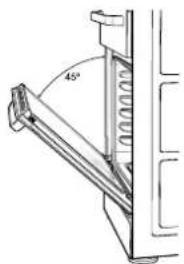
- Slowly close the door until it stops against the 'stirrups' (about 45°)
natural_image
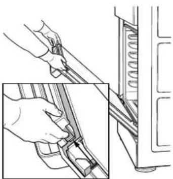
Technical line drawing of a mechanical assembly with angular dimension (45°), no visible text or symbols• To remove the top trim, press the ribbed release clips at each end and lift top trim away from the door
natural_image
Technical illustration showing hands operating a mechanical component with a spring-like extension (no text or symbols)• Using both hands, gently remove the inner glass by sliding out and lifting away from the door
- Wipe inner and outer glass gently with detergent and warm water
• Wipe clean and dry thoroughly.
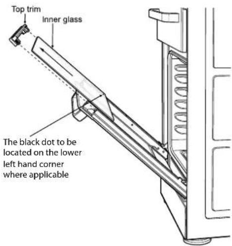
Door Inner Glass – The black dot to be located on the lower left hand corner
Re-Assembling the oven door inner glass
- Replace the inner glass back to the door with the black dot located on the lower left hand corner where applicable
- Replace the top trim ensuring the clips snap back into position
- Fully open the door, rotate the stirrups back to their original position and close the door.
! warning
DO NOT use the oven without the inner door glass fitted.
DO NOT use harsh abrasives on glass as this may damage the glass
DO NOT place glass in dishwasher.
Hand wash only with a soft cloth and warm soapy water. When dry, polish with a soft cloth and ensure the glass is dry before re-assembly.
getting to know your oven
Getting to know your new oven with this 'Simple Test Cake'
When baking, it is possible that there will be some variation in colour. Therefore, we suggest to make this simple, easy and delicious test cake to help you understand your new oven. All ovens do sometimes have hot or cold spots, therefore it is important to judge with your eye as you may need to rotate your dishes during baking.
'Simple Test Cake'
125g butter, softened to room temperature
1 cup caster sugar
1 teaspoon pure vanilla essence
4 large eggs
2 cups self-raising flour
pinch of salt
4 tablespoons (80mL) full-cream milk
Method:
- Butter base and sides of two, 20cm straight-sided round or square cake pans. Then line the base with grease proof paper or baking paper
- Preheat oven to moderate '180°C' (170°C fan forced) for 30m and ensure oven shelf is in position 2 of the oven
- Cream softened butter and sugar until light in colour
- Add vanilla essence
- Add eggs one at a time, beating well after each addition
- Sift flour and salt into the mixture and beat until well combined
- Add milk and beat or stir to combine
- Spoon mixture equally between prepared cake pans
- Bake in preheated oven, position 2 for about 25 to 35 minutes. Tip: Insert a fine cake skewer into the cake mix. If it comes out clean, or if the edges of the cake have come away slightly from the sides of the cake pan, the cake is ready.
- Remove from oven and place on wire cake rack and rest for 5 minutes before removing from cake pans. Cool completely.
To Serve: sandwich together with your favourite jam or conserve, and dust top with pure icing sugar.
FOOT NOTE: if desired, substitute butter for either margarine or olive oil spread.
Recipe is based on the Australian standard metric 250mL cup and 20mL tablespoon sets.
The following is intended as a guide and experience may show some slight variation in order to meet individual requirements. Where the gas models vary from the electric models, details for gas cooking is shown in brackets. For best results when baking, preheat your oven for 30 minutes.
| Food Conventional Oven Fan forced oven Time in minutes | |||||
| Temperature °C Oven shelf position* Temperature °C Oven shelf position* | |||||
| Plain or fruit scones 220 2 (3) | 210 Any 10 -15 | ||||
| Rolled biscuits | 170 (180) 2 150 (170) Any 10 -15 | ||||
| Spooned biscuits | 190 2 180 Any 12 -15 | ||||
| Shortbread biscuits | 160 1 or 2 150 Any 30 - 35 | ||||
| Hard individual meringues | 110 2 100 Any 90 | ||||
| Soft individual meringues | 180 2 165 Any 15 - 20 | ||||
| Pavlova - 6 eggs | 110 (120) 1 100 Any 75 | ||||
| Patty cakes | 190 2 180 Any 15 - 20 | ||||
| Sponge - 4 eggs | 180 2 170 Any 20 - 30 | ||||
| Plain butter cake | 180 2 170 Any 25 - 40 | ||||
| Rich fruit cake | 140 (150) 2 130 Any 180 | ||||
| Shortcrust cornish pasty" 200 (200/180) 2 180 (180/160) Any 40 - 45 (10/35) | |||||
| Shortcrust custard tart | 200/180(220/180) 1(3) | 190/170(200/180) Any | Any | 20 - 30 (10/25) | |
| Cream puffs | 210 2 200 Any 25 - 30 | ||||
| Yeast bread | 210 1 200 Any 25 - 30 | ||||
| Pizza | 220 2 220 Any 15 - 25 | ||||
* Shelf position is counted from the bottom shelf up. Bottom shelf position is 1.
Turn down temperatures shown.
| Meat/Poultry/Fish | Recommended temperature ^ Minutes per kilogram | ||
| Beef | - Rare | 200 | 35 - 40 |
| - Medium | 200 | 45 - 50 | |
| - Well done 200 | 55 - 60 | ||
| Lamb | - Medium | 200 | 40 |
| - Well done 200 | 60 | ||
| Veal | 180 | 60 | |
| Pork | 200 | 60 | |
| Chicken | 180 - 200 | 45 - 50 | |
| Duck | 180 - 200 | 60 - 70 | |
| Turkey | 180 | 40 - 45 (less than 10kg)35 - 40 (more than 10kg) | |
| Fish | 180 | 20 | |
| Problem causes What to do | ||
| Uneven cooking Incorrect shelf position | Select shelf that puts food in centre of oven | |
| Oven tray too large Try other trays or dishes | ||
| Trays not in centre Put trays in centre | ||
| Air flow in oven uneven Rotate food during cooking | ||
| Grill tray affecting thermostat Remove grill tray from oven on bake modes | ||
| Baked products too brown on top Oven | not preheated Preheat the oven | |
| Baking tins too large for recipe Use correct size tins | ||
| Baking tins not evenly spaced Stagger baking tins at least 3cm between tins and the oven walls | ||
| Products not evenly sized or spaced on trays | Make into same size and shape and spread evenly over trays | |
| Baked products too brown on bottom | Baking tins too large Use correct size tins | |
| Baking tins are dark metal or glass Change to shiny, light tins or lower the temperature by 10°C | ||
| Food too low in oven Cook one shelf higher | ||
| Oven door opened too frequently during baking | Don't open the oven door until at least half the cooking time has passed | |
| Baking temperature too high | Lower the temperature | |
| Grill tray affecting thermostat Remove grill tray from oven on bake modes | ||
| Cakes have a cracked thick crust | Baking temperature too high | Lower the temperature |
| Food too low in oven Cook one shelf higher | ||
| Cake batter over mixed Mix just long enough to combine the ingredients | ||
| Baking tin too deep Check size of tin and use recommended size | ||
| Baking tins dark | Change to shiny light tins | |
| Baked products are pale, flat and undercooked | Baking temperature too low | Raise the temperature |
| Food too low in oven Cook one shelf higher | ||
| Baking time too short | Increase cooking time | |
| Incorrect baking tin size | Use correct size tin | |
| Cakes fallen in centre | Baking temperature too low | Raise the temperature |
| Baking time too short | Increase cooking time | |
| Proportions of ingredients incorrect for recipe | Check recipe | |
| Opening door too early during baking | Do not open door until the last quarter of cooking time | |
| Roast meat and potatoes not brown in fan oven | Poor hot air circulation | Elevate food onto a rack to allow air circulation |
| Grill tray affecting thermostat Remove grill tray from oven on bake modes | ||
| Juices running out of meat | Do not pierce meat with fork, turn with tongs | |
| Grilled meats overcooked on outside and raw in the centre | Grill at lower insert position | |
| Grilled chops and steaks curling | Cut into fat every 2cm (3/4") |
trouble shooting
If you have a problem with your appliance check the following before you ring the service line.
| Problem What to do | |
| Operational problems | Check the electricity is turned on |
| ie: Oven, grill or hob not working | Check your fuses. If the fuse continues to blow, call the Service Centre |
| Check the circuit breaker | |
| Ensure correct knob is turned | |
| Gas only – Dry or clean ignition electrodes | |
| Gas only – Make sure flame ports and ignition areas are clean and dry | |
| Gas only – Check gas supply is on | |
| Gas only – Ensure cap/crown correctly fitted. | |
| Replace or tighten light globes (where fitted) | |
| Heat up problems Oven not pre-heated – Pre-heat oven for 30 minutes | |
| Unit smoking odours Turn oven/grill on high to remove protective oils | |
| Condensation | Reduce the amount of water used for cooking |
| Note: some condensation is normal and is to be expected during cooking | Leave the door open after cooking if food remains in cooker for warming |
| Timer not audible Turn Timer knob past 15-minute mark then to the required number of minutes | |
| Oven shelf tight Remove shelf and insert as per diagram | |
When you need information, service or replacements please quote:
-
Model Number
-
Serial Number: You can find these on the data plate, which can be seen when the oven door is open. If you need more information, please contact the Customer Care Centre on 1300 363 640 (Australia – Centre is open 8.00am to 5.00pm Monday to Friday EST) Or 09 573 2384 (New Zealand – Centre is open 8.00am to 5.00pm Monday to Friday). Only authorised service centres should carry out servicing. Otherwise warranty may be void. If you have a warranty or spare parts enquiry, you should call the numbers listed on the back page.
installation
Location
The appliance has been designed to fit in a 550mm wide gap in kitchen cabinets or free space either side. Make sure the top of the cooker is at least 10mm higher than the level of the bench top.
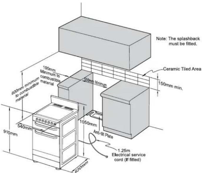
! warning
In order to avoid accidental tipping of the appliance (for example, by a child climbing onto the open oven door), the anti tilt plate and stabilising bolt MUST be installed.
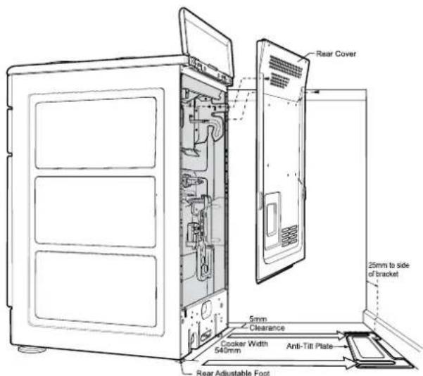
Position anti-tilt plate to the rear wall and 25mm from side of cupboard. Securely fix anti-tilt plate to the floor with fasteners. Adjust levelling feet on cooker as required.
natural_image
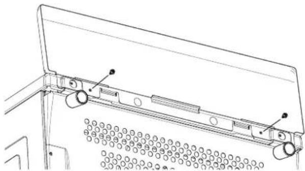
Technical line drawing of a mechanical assembly with no visible text or symbolsSplash back must be fitted to the rear using two screws provided
Stabilising bolt
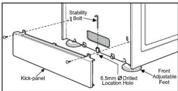
- Remove oven door - to be done by qualified personnel only. (Refer to procedure).
- Remove screws from kick panel. To remove kick panel lift kick panel upwards to release the two Location Tabs from the holes in the bottom of the panel
- Position cooker into the ant-tilt plate and then mark the position for the Stability Bolt hole on the floor
- Pull cooker out and drill the bolt hole, using a 6.5mm masonry or wood drill. Minimum 30mm deep for concrete
- Reposition cooker back into place and fit the Stability Bolt through the slot and into the drilled hole
- If the cooker is placed on a base, measures must be taken to prevent the appliance slipping from the base.
WARNING
For your safety this cooker is designed to be moved out of position by a qualified person only.
Procedure to remove the door
(to be done by qualified personnel only)
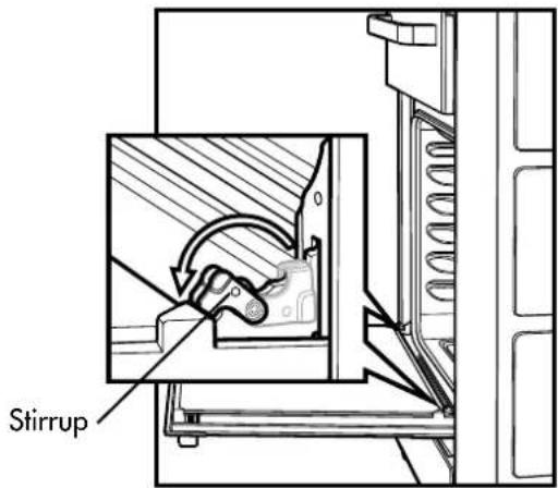
- With door fully open, rotate the two stirrups to its rest position (to engage the stirrups).
natural_image
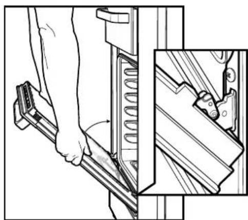
Technical illustration of a mechanical assembly with a hand pressing down on a spring component, showing a close-up inset (no text or symbols)- Close the door until it stops against the stirrups.
natural_image
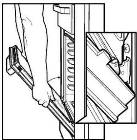
Technical illustration of a hand operating a mechanical component with a close-up view of the internal structure (no text or symbols)- Close the door further.
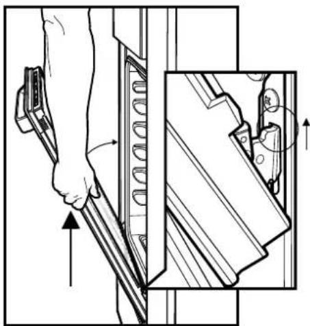
natural_image
Technical diagram showing a hand operating a tool on a panel, with an inset close-up of the component (no text or symbols present)- Lift the door slightly and evenly while continuing to slowly close the door.
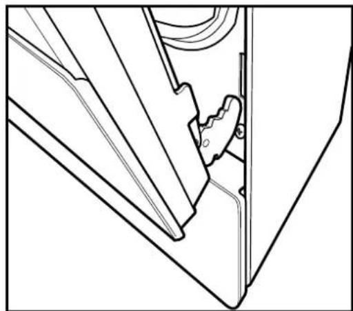
natural_image
Technical line drawing of a mechanical component or bracket assembly (no text or symbols)- Remove the door by lowering gently and pull away from the frame of the oven. Care should be taken not to damage kick panel and other parts of the cooker.
Procedure to assemble the door (to be done by qualified personnel only)
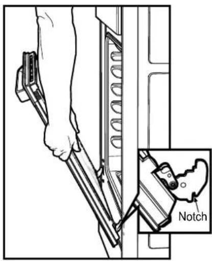
-
Hold door with both hands.
-
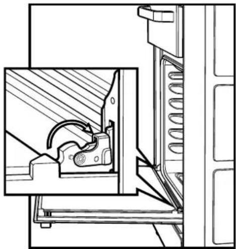
Locate both hinges into the frame slots at the same time.
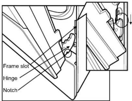
- Ensure that the location notch drops into frame slot. Care should be taken not to damage other parts of the cooker.
natural_image
Technical line drawing of a mechanical assembly with internal components and directional arrows (no text or symbols)-
Open door fully and rotate stirrups away from you back to their original position.
-
Close the door fully.
Electric wiring requirements
The cooker MUST be installed in compliance with
• Wiring connections in AS/NZS3000 Wiring Rules
- Local regulations, municipal building codes and other statutory regulations
• Data Plate – Gives information about the rating and is located behind the bottom of the oven door
- Circuit diagram – Is located on the back panel of the appliance
- A functional switch MUST be provided near the appliance in an accessible position (AS/NZS3000 – Clause 4.7.1)
- Wiring MUST be protected against mechanical failure (AS/NZS3000 – Clause 3.9)
- The cooker requires a means of all pole disconnection incorporated into the fixed wiring. This MUST have a disconnection gap of 3mm
• The cooker MUST be properly earthed
- When connections are made to a multiphase 230/240V supply, the bridge piece MUST be removed from between the active connections
- If the supply cord is damaged, it must be replaced by the manufacturer, its service agent or similarly qualified persons in order to avoid a hazard.
Hard wiring
- Remove rear panel
- Fit wires through hole at bottom centre using the appropriate gland to protect insulation of wires from the hole edge. Note that the secondary insulation of the wires will probably need to be removed to fit through gland. If the conduit to appliance is required to bend due to rear wall an elbow may be required to achieve this
- Set the length of wiring from the gland to terminal block, ensuring length is sufficient but not excessive
- Make connections to terminals and engage wires into plastic clip. Cable tie as per diagram and secure plastic clip with two long screws supplied
- Replace rear cover.
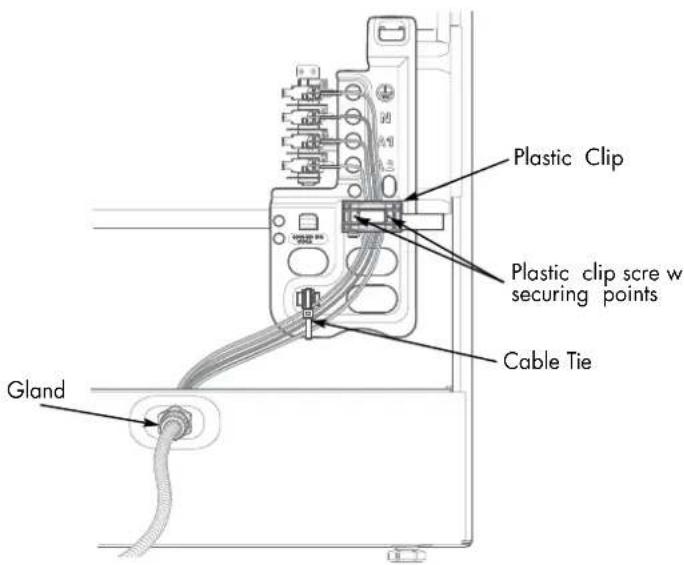

Warning! Ensure wires cannot contact hot element ends or sharp edges.
Gas requirements
This appliance must be installed by an authorised person, according to all codes and regulations of:
• AS/NZS 5601.1 (particular attention to clause 6.10.1 and figure 6.3 on page 97, and clause 6.10.1.11)
- Local gas fitting regulations, municipal building codes and other statutory regulations.
The cookers come in three gas types:
Natural gas, Propane and Universal LPG. If the cooker is required to use ULPG, a conversion kit can be obtained by contacting the Customer Care Centre for details. Before installation, check that the cooker is suitable for the gas supply by looking at the data plate behind the bottom of the oven door.
The following table shows the supply and operating pressures for various supplies.
| Gas type Natural gas Universal LPG Propane | |||
| Supply pressure at inlet to appliance regulator (if fitted) | 1.13 (kPa) Minimum | 2.75* (kPa) 2.75* (kPa) | |
| Operate pressure at appliance test point | 1.00 (kPa) 2.75 (kPa) 2.75 (kPa) | ||
*If the regulator is placed upstream of the cooker inlet, as is normal for cookers operating on LPG, then the supply pressure and operating pressure are the same. The following table shows the injector sizes for each burner.
The following table shows the injector sizes for each burner.
| Injector Natural gas Universal LPG Propane | |||
| Low heat burner 1.00 mm 0.55 mm 0.62 mm | |||
| Medium heat burner 1.35 mm 0.70 mm 0.82 mm | |||
| High heat burner 1.60 mm 0.90 mm 0.95 mm | |||
| Intense heat wok burner | 1.75 mm 1.00 mm 1.00 mm | ||
| Grill - main injector | 1.50 mm 0.82 mm 0.82 mm | ||
| Oven - main injector | 1.60 mm 0.82 mm 0.95 mm | ||
| Oven - bypass screw | 0.73 mm 0.45 mm 0.45 mm |
Checking pipe size
To work out a suitable pipe size for connection use the information in this table.
| Natural gas | Universal LPG | Propane | |||||||
| Configuration | STDHob | WOKHob | Electric Grillin Oven | STDHob | WOKHob | Electric Grillin Oven | STDHob | WOKHob | Electric Grillin Oven |
| Hourly gasconsumption for cooker | 58.7MJ | 60.4MJ | 47.6MJ | 45.9MJ | 49.2MJ | 36.9MJ | 56.5MJ | 58.3MJ | 47.5MJ |
Also use information about the length of the run, number of elbows, tees and bends, the available service pressure and the supply requirements. AS/NZS 5601.1 will help you with this matter.
Operation on NG
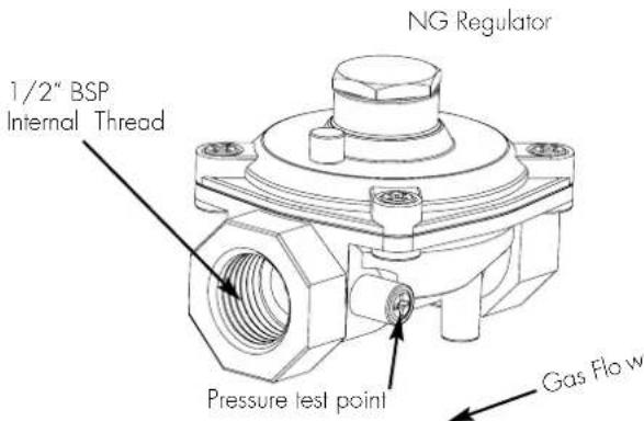
- The appliance regulator MUST be orientated so that the pressure nipple is accessible
- The arrow showing the direction of flow MUST be pointed correctly
- The regulator has a 12 " BSP internal thread at the inlet and outlet.
Wiring connection for gas cooker
To allow for disconnection of the appliance after installation, the plug must be accessible after installation, or a functional switch must be provided near the appliance in an accessible position.
If the supply cord is damaged, it must be replaced by the manufacturer, its service agent or similarly qualified persons in order to avoid a hazard.
Gas connection
Read these points before connecting to the gas supply:
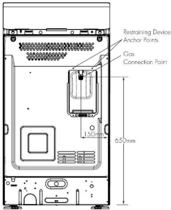
- The cooker inlet connection point has a 12'' BSP external thread. See Diagram below
• A NG regulator or a LPG test point fitting is supplied - It is recommended to fit the regulator or test point fitting to the appliance connection point, then fit either hard piping or a high level flexible connection (AS/NZS 5601.1 clauses 5.9 and 6.10.1.9) which is then attached to the consumer hard piping
• Ensure installation allows withdrawal of appliance.
Operation on universal LPG/propane
- The appliance inlet fitting provided MUST be orientated so that the pressure nipple is accessible
- The inlet fitting has 12 " BSP internal thread at the inlet and outlet.
Operation on SNG
- If the cooker is to be used with SNG, then the grill burner MUST be modified by the replacement of the shutter, which fits into the throat of the grill burner
• A conversion kit can be obtained by contacting the Customer Care Centre
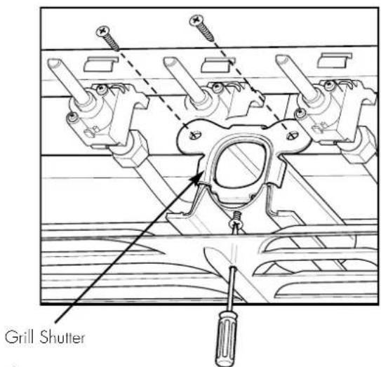
WARNING
- Disconnect electric power before removing control panel
- Remove the control panel
- Remove the existing NG shutter securing screw (refer to diagram above) and slide upwards to disengage from grill burner
- Slide the SNG shutter into position and secure with screws.
Testing the gas cooker
! warning
You MUST test the cooker after installation, before you hand it over to the customer.
You MUST have a manometer and a connecting tube.
Checking the gas supply
- Check the manometer zero point is correct
- Connect the manometer to the cooker pressure test point. This is located on the regulator or LPG inlet fitting
- Turn on the gas supply and the electricity (if applicable) and try to ignite the gas. Note: It will take additional time to light the gas for the first time, as air needs to be purged from the pipes
-
Check the operating pressure for the particular gas type (see 'Gas Type' table)
-
For LPG cookers: Adjust the regulator if necessary (this may be remote from the cooker)
- For Natural Gas cookers: Regulators are supplied pre-adjusted and configured by the component maker for use with Natural Gas. The appliance installer is not required to make an adjustment to obtain the correct outlet pressure setting. An arrow on the base of the regulator indicates the direction of the gas flow when the inlet and outlet of the regulator are orientated correctly.
- When the regulator has been fitted check for leaks from the connections with soapy water.
Checking regulator function
With the appliance operating, check the outlet pressure:
- When all the burners of the appliance are operating at maximum
- When the smallest burner of the appliance is operating at minimum, Under these conditions the outlet pressure should not vary from nominal operating pressure of 1.0kPa by more then ± 20% (ie ±0.20kPa for Natural Gas).
If the regulator appears to not be performing satisfactorily then check the following points:
- If the outlet pressure is consistently too low then
- the inlet pressure may be too low and adjustment of an upstream regulator may be needed, or
- an upstream regulator or valve with insufficient flow capacity may be present in the gas supply line. It may be necessary to repeat the checks whilst measuring both the inlet and outlet pressure to determine if the inlet pressure is in the range 1.13-5kPa.
- Check that the regulator has been fitted to the gas supply line in the correct orientation
- Replace the regulator if it fails to perform after the checks.
Testing cooker features
- Observe the flame appearance on each burner. If it is smaller or larger than expected, then the injector size needs checking
• If the flame is unsatisfactory, then refer to the Electrolux Technical Publications and correct the fault if possible - When maximum flame appearance is correct, check the turn down setting on each burner. If incorrect, proceed as follows:

WARNING
- Disconnect electric power
- Remove the control panel and adjust the bypass screw mounted on the body of each hotplate control cock
- Check the ignition on all burners both separately and in combination
- Check the operation of the electrical components, if applicable
- When operating correctly, show customer how to use the cooker
- If not operating correctly, advise the customer to ring Electrolux service. Place a warning sign on cooker or if dangerous, disconnect cooker.
notes
notes
notes
This document sets out the terms and conditions of the product warranties for Electrolux Appliances. It is an important document. Please keep it with your proof of purchase documents in a safe place for future reference should you require service for your Appliance.
1. In this warranty
(a) ‘acceptable quality’ as referred to in clause 10 of this warranty has the same meaning referred to in the ACL;
(b) 'ACL' means Trade Practices Amendment (Australian Consumer Law) Act (No.2) 2010;
(c) 'Appliance' means any Electrolux product purchased by you accompanied by this document;
(d) 'ASC' means Electrolux' authorised serviced centres;
(e) 'Electrolux' means Electrolux Home Products Pty Ltd of 163 O'Riordan Street, Mascot, NSW 2020, ABN 51 004 762 341 in respect of Appliances purchased in Australia and Electrolux (NZ) Limited of 3-5 Niall Burgess Road, Mount Wellington, in respect of Appliances purchased in New Zealand;
(f) ‘major failure’ as referred to in clause 10 of this warranty has the same meaning referred to in the ACL and includes a situation when an Appliance cannot be repaired or it is uneconomic for Electrolux, at its discretion, to repair an Appliance during the Warranty Period;
(g) 'Warranty Period' means:
(i) where the Appliance is used for personal, domestic or household use (i.e. normal single family use) as set out in the instruction manual, the Appliance is warranted against manufacturing defects in Australia for 24 months and in New Zealand for 24 months, following the date of original purchase of the Appliance;
(ii) where the Appliance is used for commercial purposes (including being used to directly assist a business or where the Appliance is used in a multi-family communal or share type environment), the Appliance will then be warranted against manufacturing defects in Australia for 3 months and in New Zealand for 3 months, following the date of original purchase of the Appliance.
(h) 'you' means the purchaser of the Appliance not having purchased the Appliance for re-sale, and 'your' has a corresponding meaning.
-
This warranty only applies to Appliances purchased and used in Australia or New Zealand and is in addition to (and does not exclude, restrict, or modify in any way) any non-excludable statutory warranties in Australia or New Zealand.
-
During the Warranty Period Electrolux or its ASC will, at no extra charge if your Appliance is readily accessible for service, without special equipment and subject to these terms and conditions, repair or replace any parts which it considers to be defective. Electrolux or its ASC may use remanufactured parts to repair your Appliance. You agree that any replaced Appliances or parts become the property of Electrolux. This warranty does not apply to light globes, batteries, filters or similar perishable parts.
-
Parts and Appliances not supplied by Electrolux are not covered by this warranty.
-
You will bear the cost of transportation, travel and delivery of the Appliance to and from Electrolux or its ASC. If you reside outside of the service area, you will bear the cost of:
(a) travel of an authorised representative;
(b) transportation and delivery of the Appliance to and from Electrolux or its ASC,
In all instances, unless the Appliance is transported by Electrolux or an Electrolux authorised representative, the Appliance is transported at the owner's cost and risk while in transit to and from Electrolux or its ASC.
-
Proof of purchase is required before you can make a claim under this warranty.
-
You may not make a claim under this warranty unless the defect claimed is due to faulty or defective parts or workmanship. Electrolux is not liable in the following situations (which are not exhaustive):
(a) the Appliance is damaged by:
(i) accident
(ii) misuse or abuse, including failure to properly maintain or service
(iii) normal wear and tear
(iv) power surges, electrical storm damage or incorrect power supply
(v) incomplete or improper installation
(vi) incorrect, improper or inappropriate operation
(vii) insect or vermin infestation
(viii) failure to comply with any additional instructions supplied with the Appliance;
(b) the Appliance is modified without authority from Electrolux in writing;
(c) the Appliance's serial number or warranty seal has been removed or defaced;
(d) the Appliance was serviced or repaired by anyone other than Electrolux, an authorised repairer or ASC.
-
This warranty, the contract to which it relates and the relationship between you and Electrolux are governed by the law applicable where the Appliance was purchased. Where the Appliance was purchased in New Zealand for business purposes the Consumer Guarantee Act does not apply.
-
To the extent permitted by law, Electrolux excludes all warranties and liabilities (other than as contained in this document) including liability for any loss or damage whether direct or indirect arising from your purchase, use or non use of the Appliance.
-
For Appliances and services provided by Electrolux in Australia, the Appliances come with a guarantee by Electrolux that cannot be excluded under the Australian Consumer Law. You are entitled to a replacement or refund for a major failure and for compensation for any other reasonably foreseeable loss or damage. You are also entitled to have the Appliance repaired or replaced if the Appliance fails to be of acceptable quality and the failure does not amount to a major failure. The benefits to you given by this warranty are in addition to your other rights and remedies under a law in relation to the Appliances or services to which the warranty relates.
-
At all times during the Warranty Period, Electrolux shall, at its discretion, determine whether repair, replacement or refund will apply if an Appliance has a valid warranty claim applicable to it.
-
For Appliances and services provided by Electrolux in New Zealand, the Appliances come with a guarantee by Electrolux pursuant to the provisions of the Consumer Guarantees Act, the Sale of Goods Act and the Fair Trading Act.
-
To enquire about claiming under this warranty, please follow these steps:
(a) carefully check the operating instructions, user manual and the terms of this warranty;
(b) have the model and serial number of the Appliance available;
(c) have the proof of purchase (eg an invoice) available;
(d) telephone the numbers shown below.
- You accept that if you make a warranty claim, Electrolux and its ASC may exchange information in relation to you to enable Electrolux to meet its obligations under this warranty.
Important Notice
Before calling for service, please ensure that the steps listed in point 13 above have been followed.
| FOR SERVICEor to find the address of your nearest state service centre in AustraliaPLEASE CALL 13 13 49For the cost of a local call (Australia only) | SERVICE AUSTRALIAElectroluxELECTROLUX HOME PRODUCTSwww.electrolux.com.au | FOR SPARE PARTSor to find the address of your nearest state spare parts centre in AustraliaPLEASE CALL 13 13 50For the cost of a local call (Australia only) |
| FOR SERVICEor to find the address of your nearest authorised service centre in New ZealandFREE CALL 0800 10 66 10(New Zealand only) | SERVICE NEW ZEALANDElectroluxELECTROLUX HOME PRODUCTSwww.electrolux.co.nz | FOR SPARE PARTSor to find the address of your nearest state spare parts centre in New ZealandFREE CALL 0800 10 66 20(New Zealand only) |
For further information on all Chef appliances, or to obtain detailed dimension and installation information, call into your Retailer, phone or email our Customer Care team or visit our website:
Australia
phone: 1300 363 640
fax: 1800 350 067
email: ...... customercare@electrolux.com.au
web:......www.chefappliances.com.au

Electrolux

Top service
Top Service encompasses the after sales service provided by The Electrolux Group to consumers including delivery, home service and spare parts.
Chef. We are part of the Electrolux family.
Share more of our thinking at www.electrolux.com
Part No. 0342 001 562 12A002A
© 2012 Electrolux Home Products Pty Ltd
ABN 51 004 762 341
Print code: CMAN_Upright_UM_Jan12
- CONGRATULATIONS
- CONDITIONS OF USE
- Record model and serial number here:
- warning
- caution
- tips and information
- environmental tips
- Contents
- Important – check for any damage or marks
- Information on disposal for users
- important safety instructions
- To avoid an electric shock or fire
- Grill warnings
- Oven warnings
- Hotplate and burner warnings
- General appliance description
- operating for the first time
- Choosing utensils for gas and electric hotplates
- Installation and service warning
- Before operating first time
- installing your oven accessories
- Fitting oven shelves
- Fitting the grill dish
- Replacing the oven light
- ! warning
- using the gas cooker
- Gas oven features and descriptions
- Gas oven conventional baking
- Gas oven fan forced baking
- Gas hotplate
- Gas oven burner flame
- Lighting gas hotplate, grill and oven
- using the electric cooker
- Electric features and descriptions
- Solid hotplates
- Ceramic Hotplates
- Electric oven conventional baking
- Electric oven fan forced baking
- Using the Grill
- Hints general
- Conventional Oven
- Fan Forced
- General tips
- Condensation and Steam
- Cleaning the cooker
- Stainless Steel
- General
- Oven
- Oven Shelves
- Oven - Grill Dish and Insert
- Gas Burners
- general hints and tips
- Cleaning the Oven Door
- To remove the inner door glass for cleaning
- Re-Assembling the oven door inner glass
- getting to know your oven
- Getting to know your new oven with this 'Simple Test Cake'
- 'Simple Test Cake'
- Method:
- Turn down temperatures shown.
- trouble shooting
- installation
- Location
- Procedure to remove the door
- Electric wiring requirements
- Hard wiring
- Gas requirements
- Checking pipe size
- Operation on NG
- Wiring connection for gas cooker
- Gas connection
- Operation on universal LPG/propane
- Operation on SNG
- Testing the gas cooker
- Checking the gas supply
- Checking regulator function
- Testing cooker features
- notes
- This document sets out the terms and conditions of the product warranties for Electrolux Appliances. It is an important document. Please keep it with your proof of purchase documents in a safe place for future reference should you require service for your Appliance.
- In this warranty
- 'Warranty Period' means:
- Australia
- Top service
Brand : Chef
Model : CFE536WA
Category : Oven