MI-302 - Flat Screen Mount Mount-It! - Free user manual and instructions
Find the device manual for free MI-302 Mount-It! in PDF.


| Product Type | Flat Panel Wall Mount |
| Brand | Mount-It! |
| Model | MI-302 |
| VESA Compatibility | Up to 400x400 mm |
| Weight Capacity | 60 lbs (27 kg) |
| Tilt Range | -5° to +15° |
| Swivel Range | ±90° |
| Leveling | ±3° |
| Material | Steel / Aluminum |
| Color | Black |
| Mounting Type | Fixed / Tilt / Full Motion |
| Wall Plate Size | 11.2 x 5.5 in (285 x 140 mm) |
| Distance from Wall | 2.8 to 18.5 in (71 to 470 mm) |
| Compatible Screen Size | 42 to 86 in |
| Cable Management | Yes, integrated |
| Installation Hardware | Included (lag bolts, concrete anchors) |
| Leveling Bubble | Yes |
| Locking Security | Optional lock |
| Weight (mount only) | Approx. 5.4 lbs (2.45 kg) |
| Certifications | UL listed, TUV |
| Warranty | 10 years |
Frequently Asked Questions - MI-302 Mount-It!
User questions about MI-302 Mount-It!
0 question about this device. Answer the ones you know or ask your own.
Ask a new question about this device
Download the instructions for your Flat Screen Mount in PDF format for free! Find your manual MI-302 - Mount-It! and take your electronic device back in hand. On this page are published all the documents necessary for the use of your device. MI-302 by Mount-It!.
USER MANUAL MI-302 Mount-It!
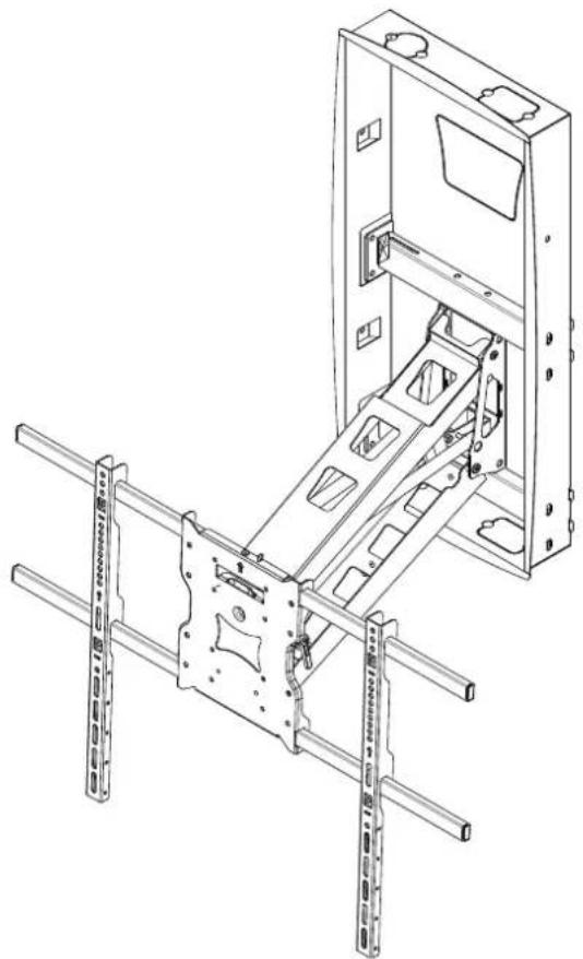
Recessed Motorized Fireplace TV Mount
natural_image
Technical line drawing of a mechanical assembly with mounting brackets and internal components (no text or symbols)
Please scan this QR code to visit the product page.
MI-302
MOUNT-IT!
INSTALLATION INSTRUCTIONS
For installation assistance or questions, please contact us at support@mount-it.com or (855) 925 5668.
Mount and Accessories
natural_image
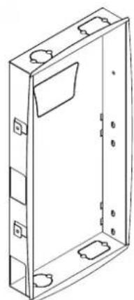
Line drawing of a rectangular enclosure with mounting holes and a recessed panel (no text or symbols)X1
A1: Recessed Box
natural_image
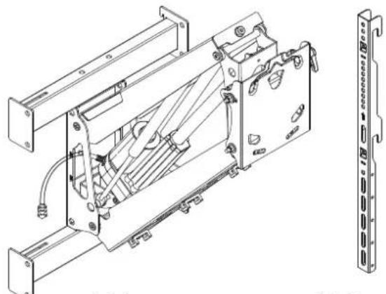
Technical line drawing of a mechanical assembly with no visible text or symbolsX1
A2: Motorized Arm
X2
A3: VESA brackets
natural_image
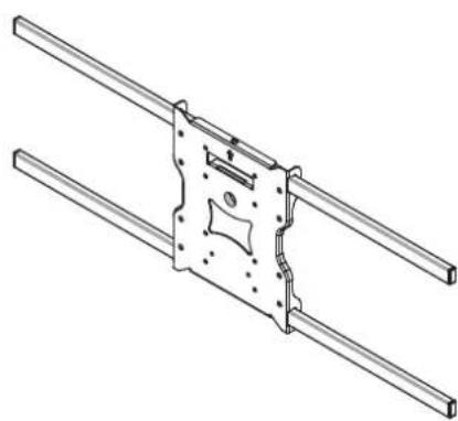
Technical line drawing of a mechanical assembly with two parallel rods and a central mounting bracket (no text or symbols)X1
A4: Universal Adapter plate
X4
X1
natural_image
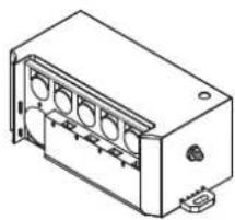
Isometric line drawing of a rectangular electronic component with multiple slots and a terminal connector (no text or symbols)X1
X1
X1
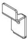
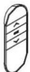
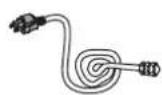
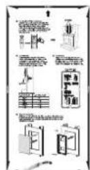
A5:Security Clips A6:Remote Control A7:Linear actuator A8:Power Cable
A9: Template
TV Mounting Hardware
A- (M4x16)-4pcs
B- (M5x16)-4pcs
C- (M6x16)-4pcs
D- (M8x25)-4pcs
E- ( 16×6.2×1.5 )-4pcs
F- Security Bolt M5x8 -4pcs
G- (M8x45)-4pcs
Wall Mounting Hardware
H- ST8x50 -10pcs
1 - Wrench -1pcs
J - (L=200mm) Cable Ties -7pcs
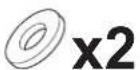
C1: M5 / M6 Washer
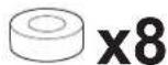
C2: 5mm Spacer
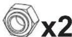
C3: M6 Nut C4: 5mm Hex Wrench
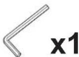
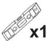
Bubble Level
Required Tools (Not Included)
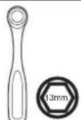

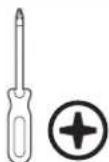
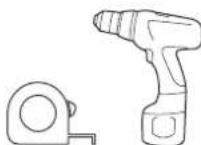
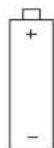
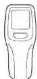


Socket Wrench Phillips Screwdriver Pencil Dr Measuring Tape
2 x AAA Batteries
Wood BitStud Finder
Select TV Bolts
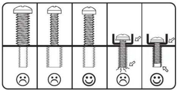
1.1 A-G Select Bolts
The back of your TV has 4 bolts holes in a square or rectangular pattern. This is where the mount will attach to your TV. We provide several sizes and lengths of bolts. This guide will help you select the right bolts for your TV. You will only use 4 of the provided bolts to attach your TV - the rest are not needed.
Select TV Spacers
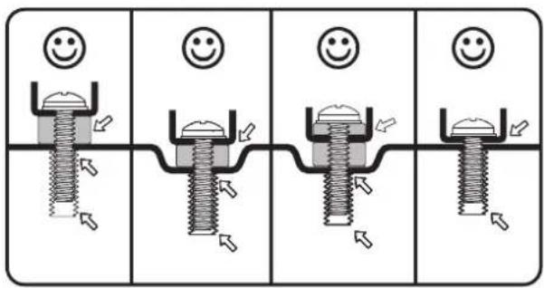
1.2 Select Spacers
Plastic spacers are also provided in 2 thicknesses to allow the mount to work with curved TVs, and TVs that have recessed mount holes, protrusions, or inputs in the way. They can also be used to prevent the TV bolts from going too deep and damaging your TV. You may not need spacers for your TV.
TV Compatibility :
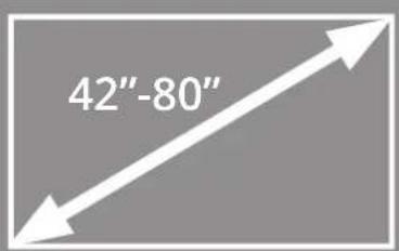
- Compatible with displays from 42"-80"
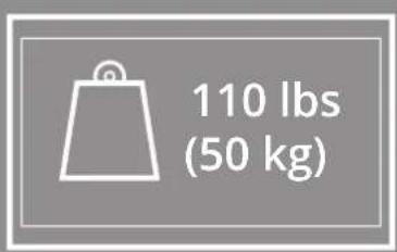
• Max Load Capacity: 110lbs(50kg)
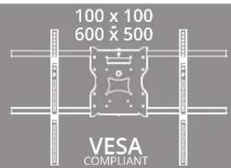
• VESA Compatibility: (100x100 - 600x500)
Note: Displays smaller than 65" may not completely hide the mounting arm and the recessed box components from view. User may adjust the vertical position of the tv by mounting the tv on the higher or lower end of the vertical VESA brackets to hide the arm or the top of the housing.
Remote Control Operation
Press and hold the "△" button to lift the mount.
Press and hold the "▽" button to lower the mount.
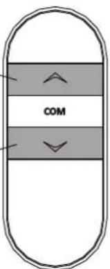
Control Unit Specifications
Remote control pairing switch
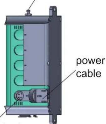

Linear actuator
Input:100-240V\~50/80Hz,Max.200W
Output:24V 4.5A/Linear actuator
Continuous operation of the motor might initiate a mandatory rest period, this is not a malfunction but a protection measure.

Pairing the Remote: Press the UP and DOWN buttons on the remote control at the same time, then press and hold the PAIRING button on the control unit until the red light flashes on the remote.
Installation
1 Mandatory Installation Requirements (Locate the Studs)
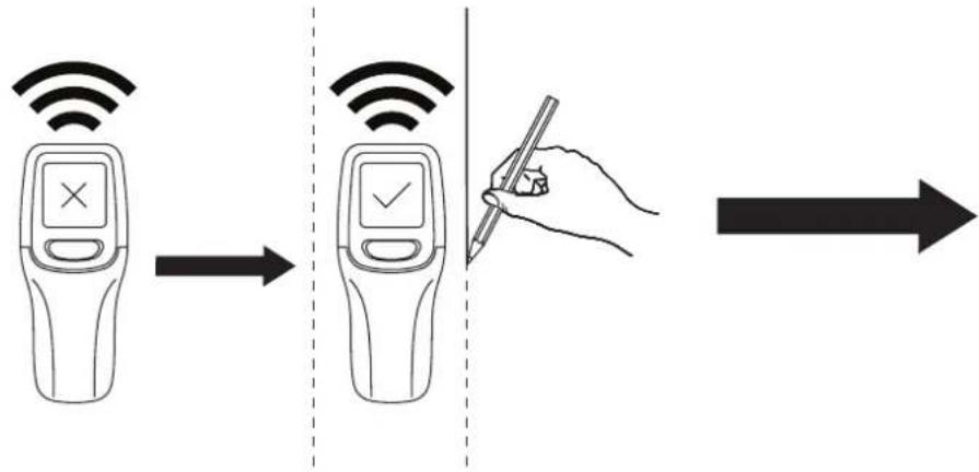
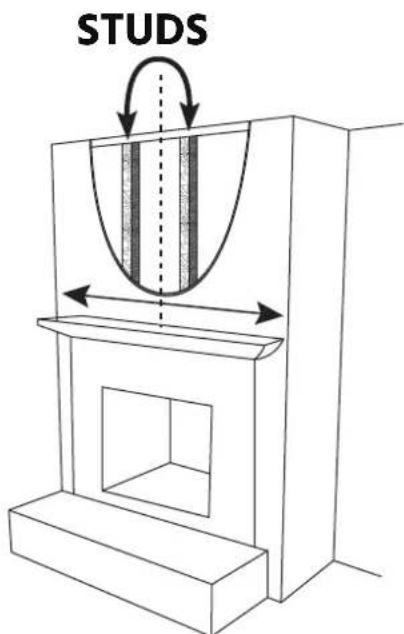
Use a stud finder to locate the studs in your wall, then mark the edges of each stud with a pencil. Note: The studs will need to be the commonly used spacing of 16" from center to center (14.5" from inner edge to inner edge.) If they are farther or closer apart, this mount cannot be installed without modifying the stud spacing or adding additional supports. We recommend using a professional contractor if you are unable to make the necessary changes yourself.
- This mount is for use above decorative fireplaces, avoid installation over fireplaces if the temperature exceeds 100F above the mantel.
- Wall must be wood stud frame, 2 studs are required to mount the recessed box, spaced at 16" center to center.
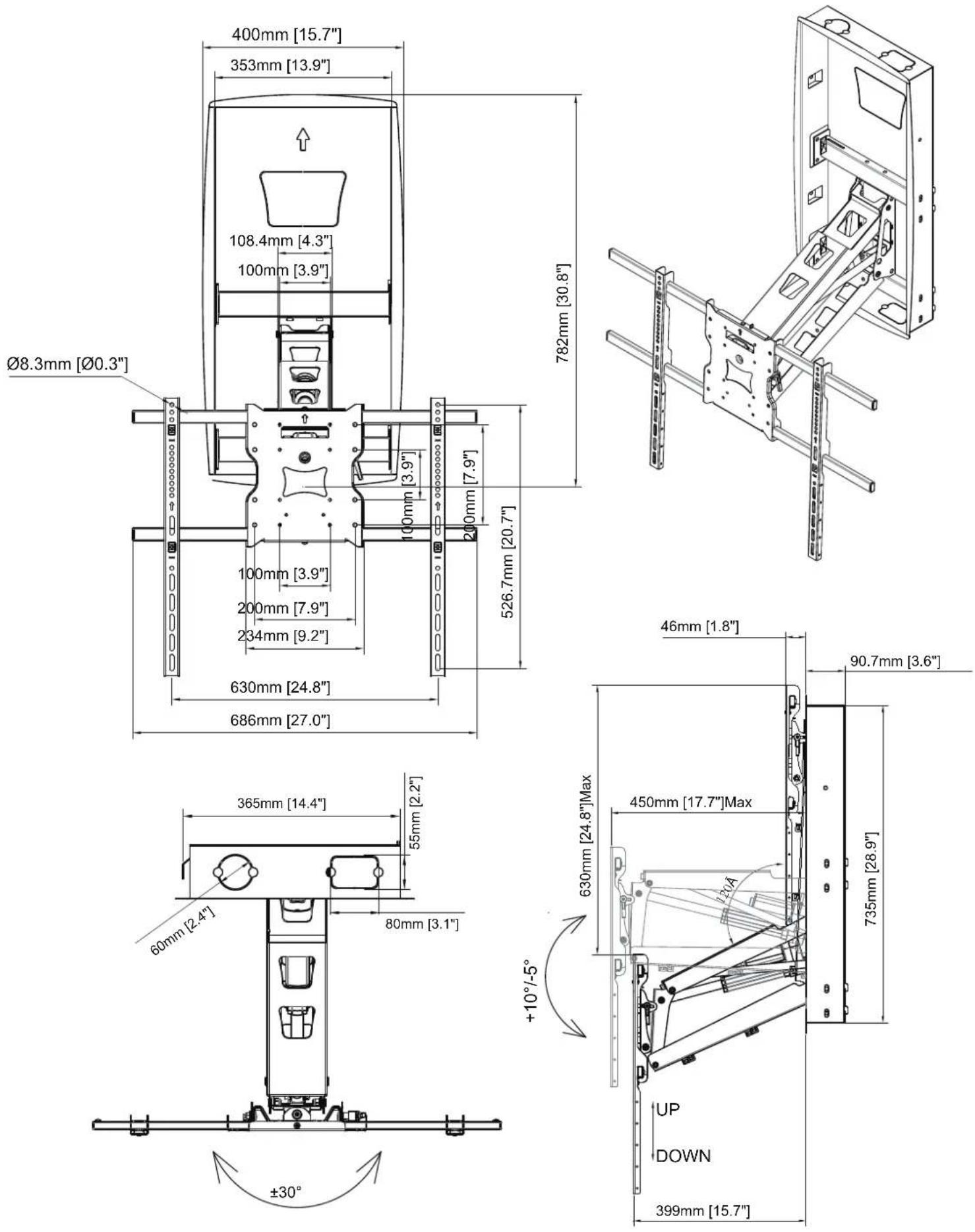
- Mantel depth should not exceed 15.5" from the wall, or the mount arm will be unable to clear the mantel. Larger mantels may limit the maximum swivel angle of the TV.
- Minimum Height Requirements: Adequate clearance is required between the bottom of the recessed box and the top of the mantel. This clearance is determined by the depth of the mantel. Please ensure adequate vertical space is available to accommodate both the mount and TV in the raised position so that the top of the TV has clearance from the ceiling. Use the chart below to determine the minimum vertical clearance required between the bottom of the recessed box and the top of the mantel.

Above Fireplace
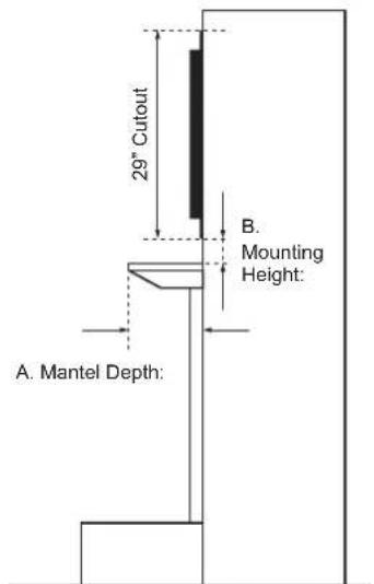
| A. Mantel Depth | B. Mounting Height |
| ≤ 3.94” | +2” |
| ≤ 7.67” | +3.1” |
| ≤ 11.81” | +4.67” |
| ≤ 13.78” | +5.67” |
| ≤ 15.70” | +12.13” |

Recessed Box Preparation
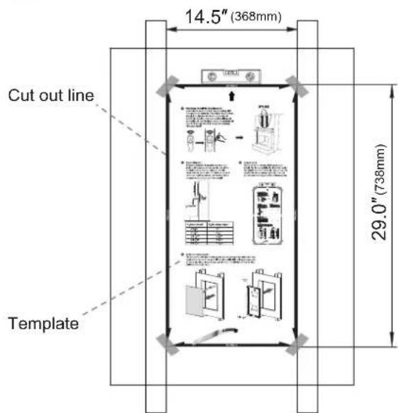
Use a drywall saw and the Template (#A9) to cut a hole to fit the Recessed Box (#A1), please reference the diagram to be sure you understand the dimensions required. The hole will need to be 14.5" wide from stud to stud, and 29.0" from top to bottom.
3 Insert the Recessed Box
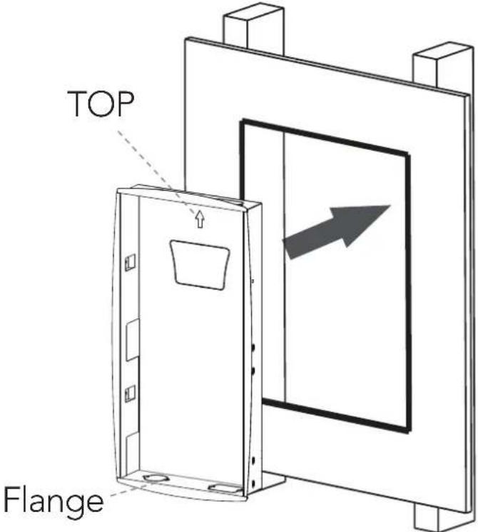
The box comes with tabs to firmly hold the box between the studs and may require force to insert the box fully into the wall until the flanged edges rest on the wall surface.
It may be required to insert the left side of the box first until the tabs are in place.
4 Secure the Recessed Box
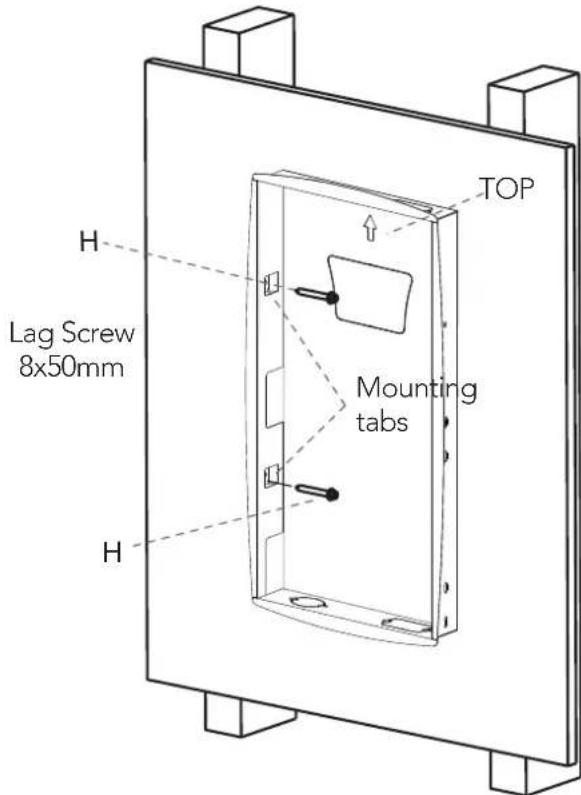
Install 2 Lag Screws only on the left-hand side of the Recessed Box in the locations shown. This will secure the box in place for the upcoming steps.
Note: The control unit may arrive attached to the inside of the Recessed Box for shipping purposes. Please remove it before installing the Recessed Box.
5 Insert the Motorized Arm
natural_image
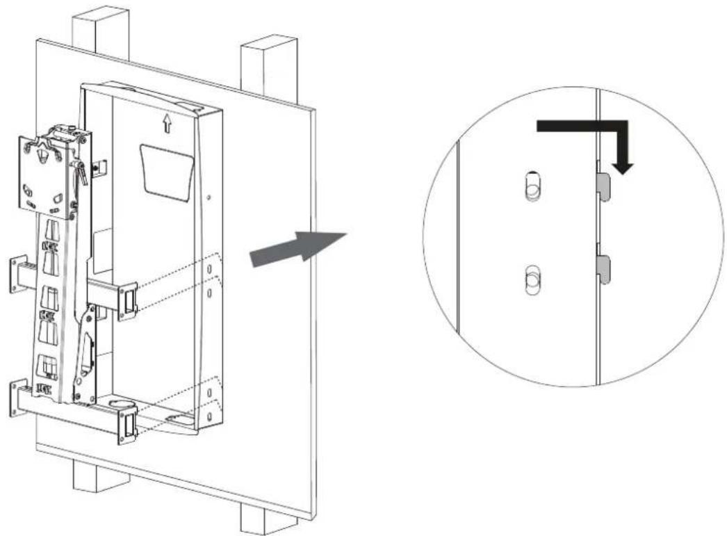
Technical line drawing of a door frame with an arrow indicating direction, plus a magnified inset showing internal components (no text or symbols)Insert the Motorized Arm into the Recessed Box and hook the tabs in place as shown in the magnification bubble.
6 Extend the Arm Supports
natural_image
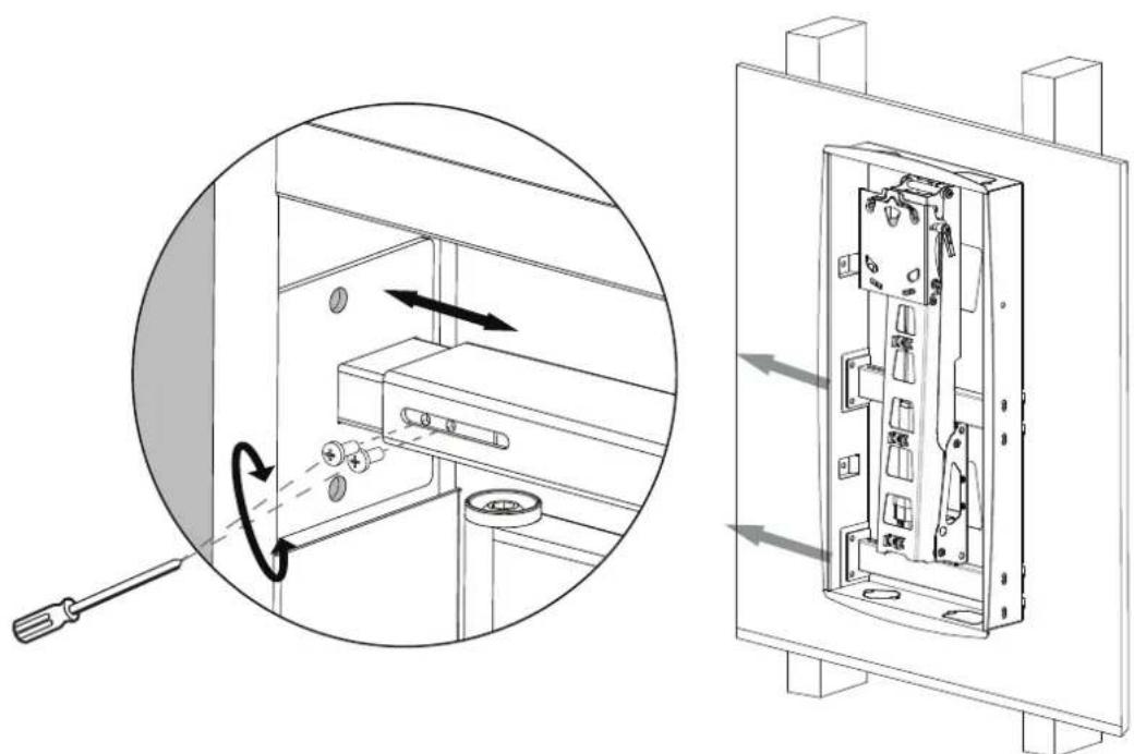
Technical diagram showing a mechanical assembly with a magnified inset of the internal components (no text or symbols present)Extend the arm supports on the left-hand side of the Motorized Arm. Loosen or remove the screws on that side as shown in the magnification bubble, slide the arms until they are secure against the studs through the left-hand side of the Recessed Box, and reinstall or retighten the screws to secure it in place.
7 Install the Lag Screws
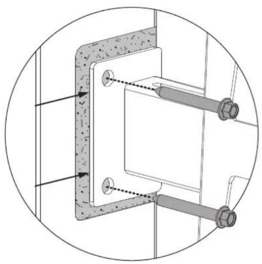
Tip: Press the mounting arms to the rear of the holes so that they are installed as far back on the stud as possible. This will allow the TV to reach the smallest profile distance between the TV and wall.
natural_image
Technical diagram of a mechanical assembly with two bolts and a central component, enclosed in a circular frame (no text or symbols)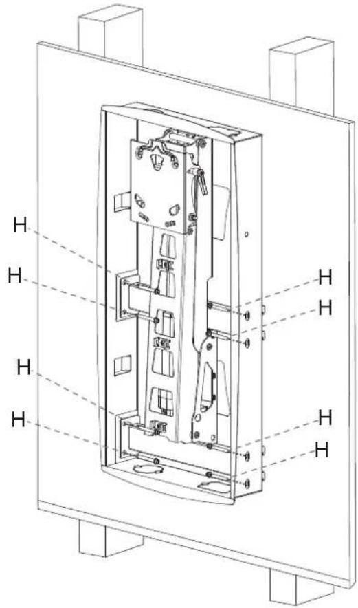
Install the 8 remaining Lag Screws in the locations shown so that they pass through the holes on both the Motorized Arm and Recessed Box.
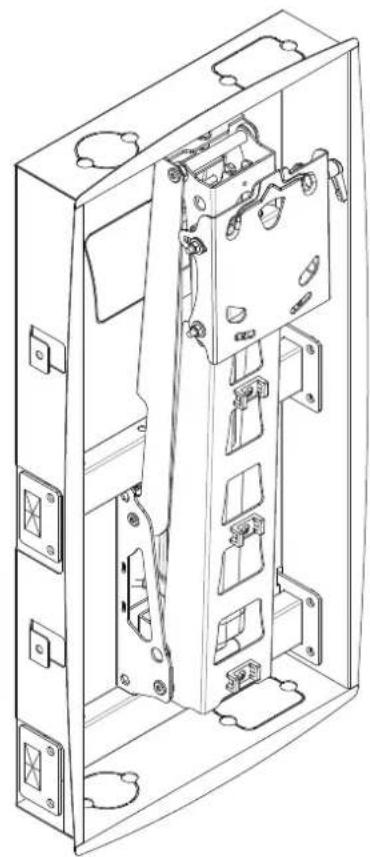
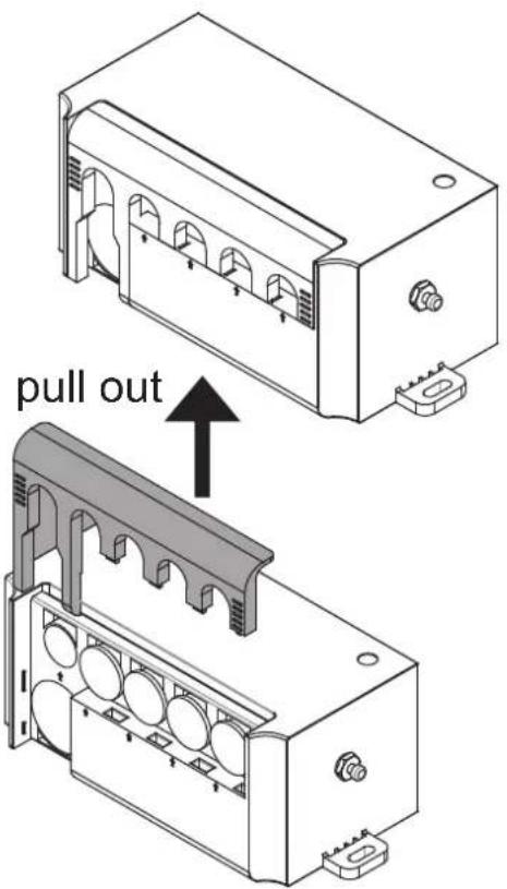
8 Locate the Power Cable Remove 9e Cover from
natural_image
Technical line drawing of an open electrical enclosure with internal compartments and mounting holes (no text or symbols)the Control Unit
10 Connect the Power
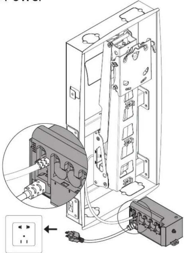
Connect the cable from the motorized arm to the control unit, then connect the plug to a wall outlet. Note: Power/cable ports are provided in the top, bottom and back of the recessed box for alternate power and AV options/connections. Knock out the pre-cut ports as needed to run your cables.
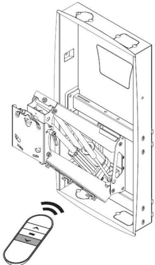
11 Lower the Arm
natural_image
Technical line drawing of an open electrical enclosure with internal components and a remote control interface (no text or symbols)Press the down arrow on the remote control to lower the motorized arm to its lowest position.
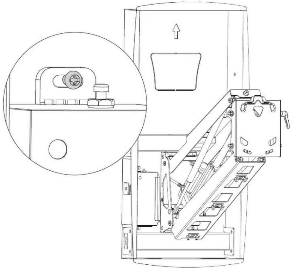
12 Install the Control Unit
natural_image
Technical line drawing of a mechanical device with an inset close-up showing a component detail (no text or symbols present)Attach the Control Unit to the inside of the Recessed Box, next to the Motorized Arm in the location shown. Secure it in place using Screws.
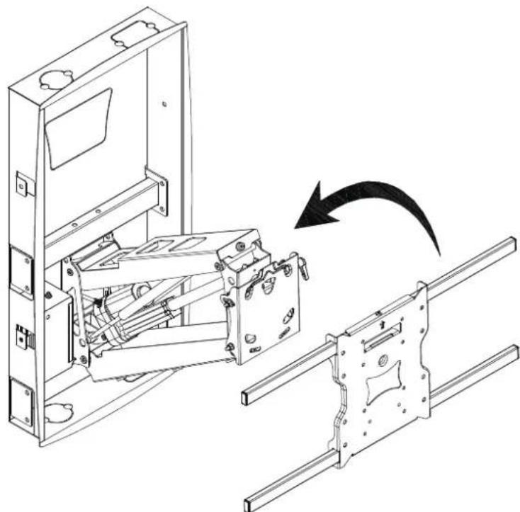
13 Install the VESA Plate
natural_image
Technical line drawing of an electrical enclosure with internal components and a rotating arrow indicating rotation (no text or symbols)Locate the arrow on the VESA Plate to ensure the correct side is facing up, then hang the VESA Plate on the end of the Motorized Arm.
14 Secure the VESA Plate
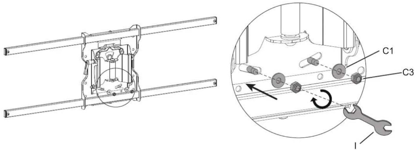
Install Washers (#C1) and Nuts (#C3) onto the bolts protruding through the back of the plate. These nuts will also be used in the final adjustments to level the screen if needed.
15 a: Attaching the TV to the VESA Arms For TVs with VESA Patterns 300x200-600x500.
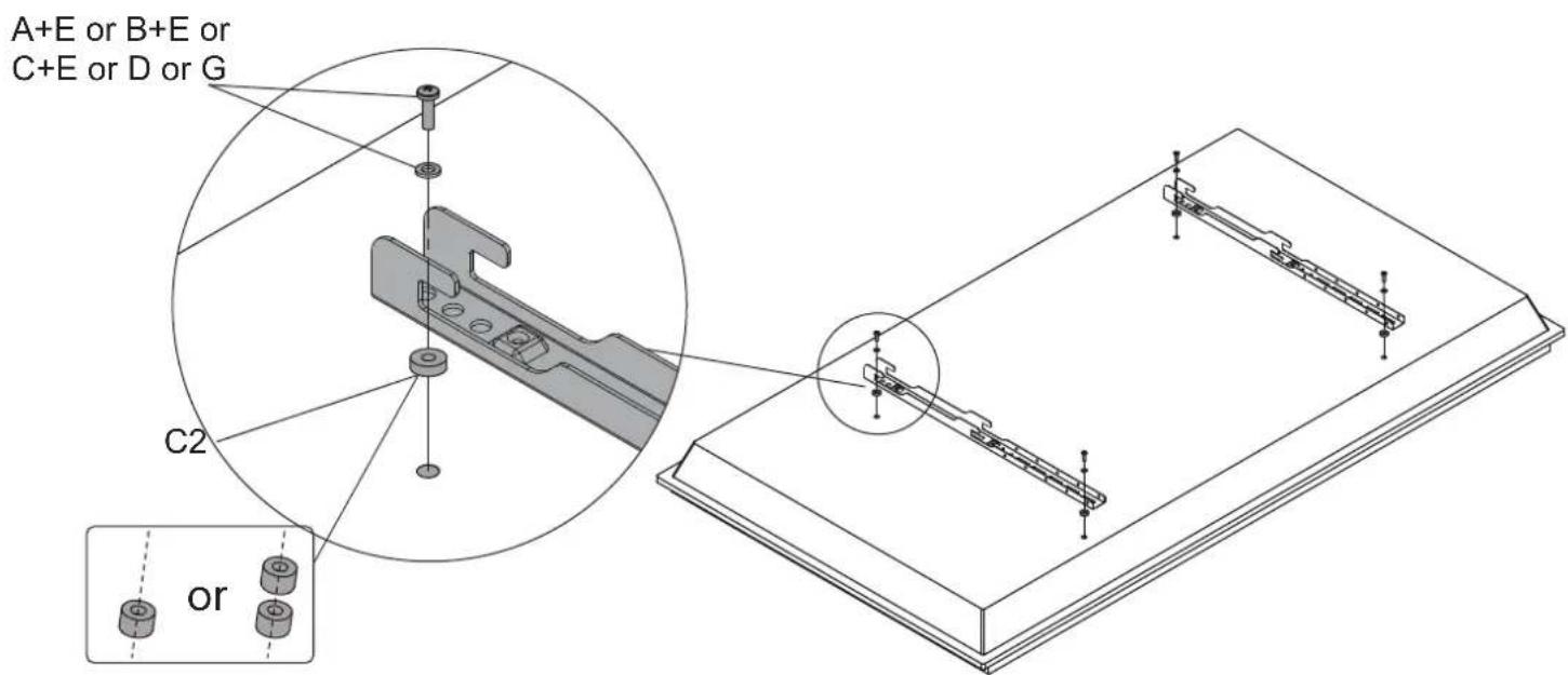
Select the appropriate size mounting bolt (Select one size #A, #B, #C, #D or #G) and washer (#E) for your display's mounting holes and verify the length of the VESA bolt is not too long. If you are unsure of the correct bolt size for your display refer to your display's user manual or contact the display's manufacturer for sizing information. If necessary, use the included spacers (#C2) between the mount and the screen as shown above to adjust the length of the mounting bolt. Multiple spacers can be used in combination to achieve the desired bolt depth. Attach the VESA Arms using the selected bolts and tighten until secure. Do not overtighten.
15b: Attaching the TV to the VESA Plate
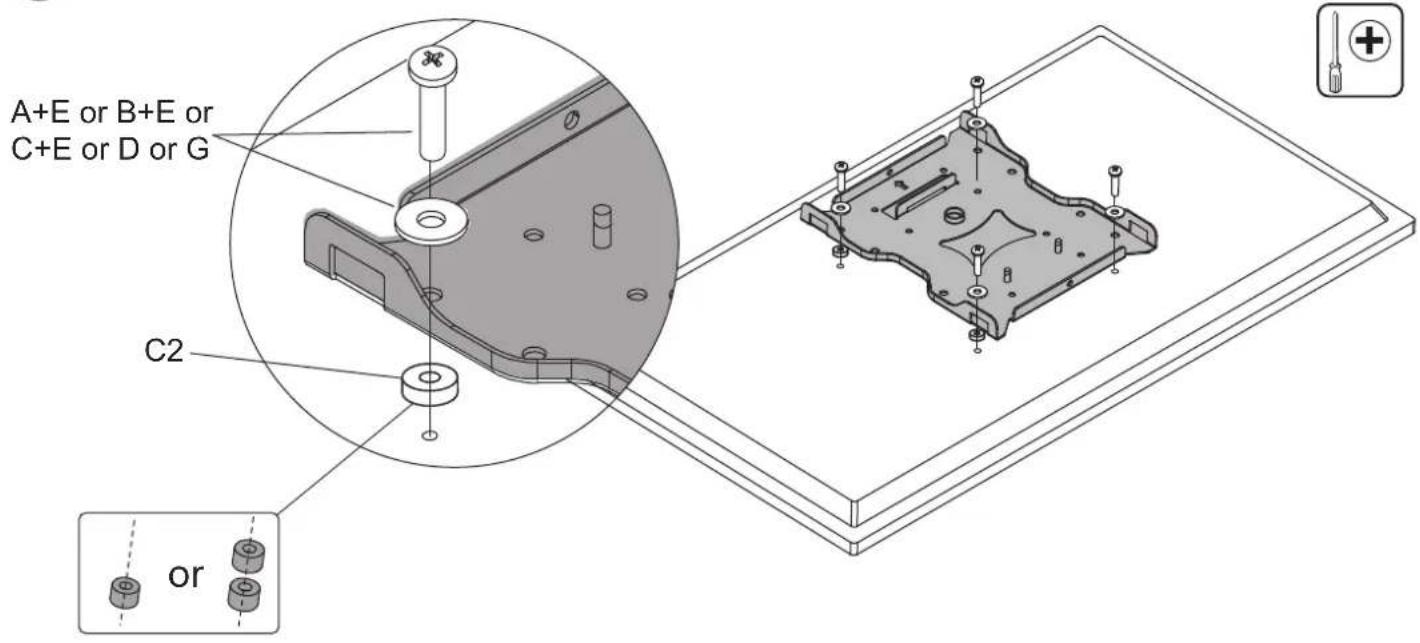
For TVs with a VESA pattern of 200x200 or less remove the horizontal crossbars from the VESA Plate. Select the appropriate size mounting bolt (Select one size #A, #B, #C, #D or #G) and washer (#E) for your display's mounting holes and verify the length of the VESA bolt is not too long. If you are unsure of the correct bolt size for your display refer to your display's user manual or contact the display's manufacturer for sizing information. If necessary, use the included spacers (#C2) between the mount and the screen as shown above to adjust the length of the mounting bolt. Multiple spacers can be used in combination to achieve the desired bolt depth. Attach the VESA Plate using the selected bolts and tighten until secure. Do not overtighten.
16 Hang the TV on the Motorized Arm
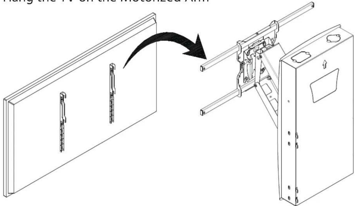
Hang the TV on the mount arms as shown in the diagram. Caution: Two persons recommended for safe lifting and easier installation.
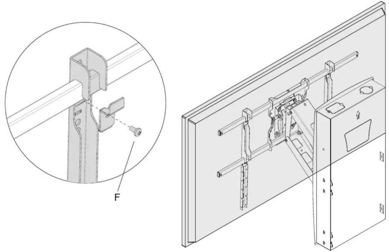
17 Securing The TV On The Mount
natural_image
Technical line drawing of a mechanical assembly with an inset showing a close-up of a bracket component labeled 'F' (no text or symbols present)Center the TV on the mount arm so that the weight of the TV is balanced, then attach the 4 Security Clips in the locations shown and secure in place using Security Bolt (#F).
18 Leveling Adjustment -5° - +5°
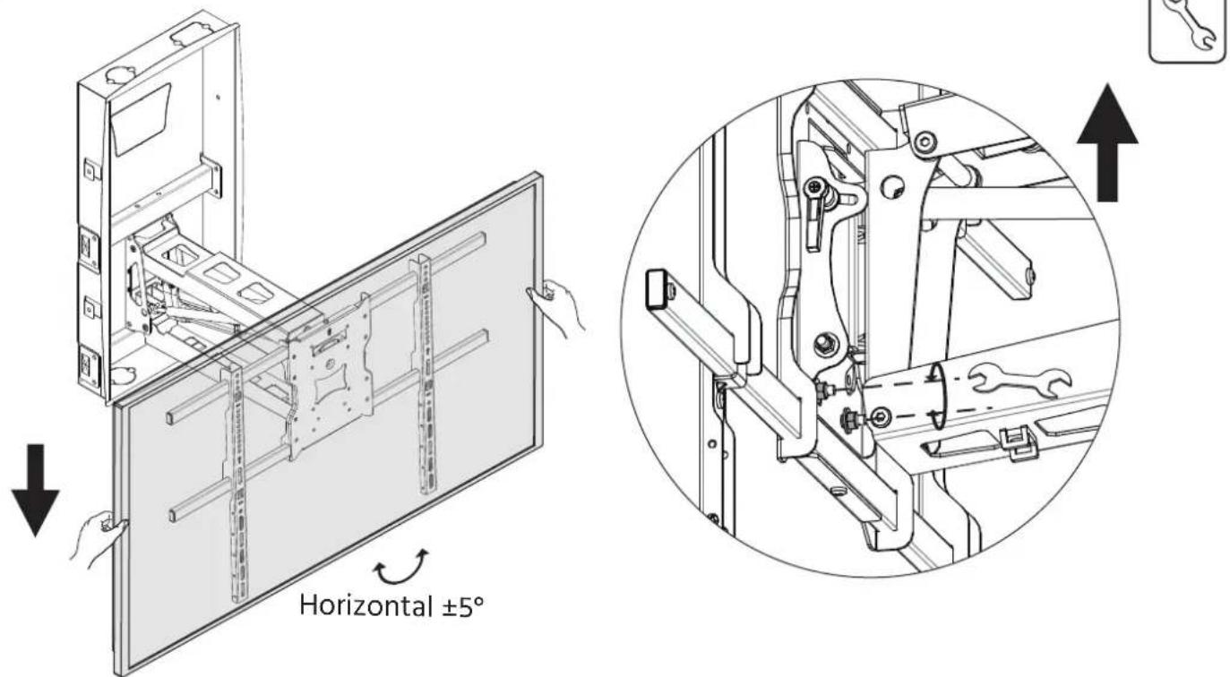
The mount allows up to 5 degrees of levelling adjustment post installation. To adjust the level of the TV, place a bubble level on top of the TV, loosen the 2 nuts located behind the VESA plate (shown in the magnification bubble) level the TV and tighten the 2 nuts again to lock the TV in position.
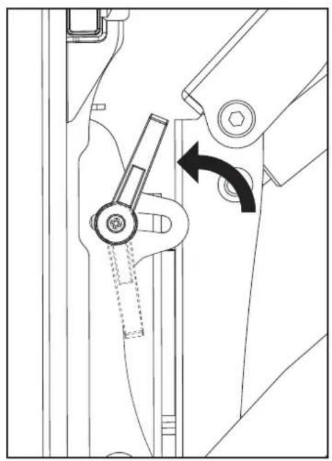
19 Tilt Adjustment -5^ - + 10^
natural_image
Technical line drawing of a mechanical assembly with no visible text or symbols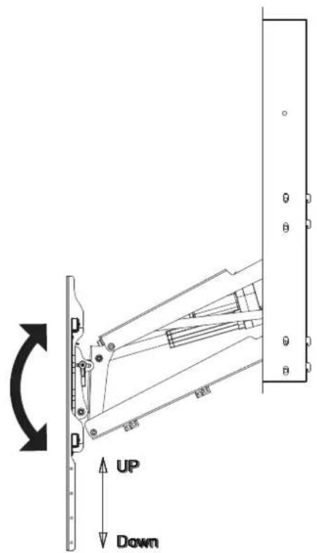
The mount can tilt down up to 10 degrees and up 5 degrees. To adjust the tilt angle of the TV, loosen the tilt adjustment lever shown here then adjust the tilt to the desired angle and tighten the tilt adjustment lever back down.
Note: If the screen tilts down slowly over time adjust the screen back to the proper angle and ensure the tilt adjustment lever and the nut on the opposite side are firmly tightened.
20 Swivel Adjustment -30° - +30°
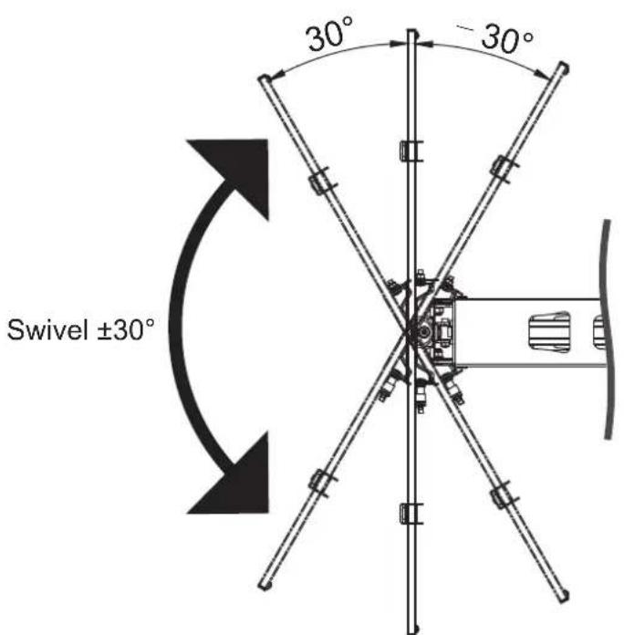
The mount can manually swivel 30 degrees left and right. To adjust the swivel angle of the TV, push carefully on the edge of the screen until you reach the desired viewing angle. WARNING: Before raising the mount swivel the TV back until it is parallel to the wall. If the TV is angled toward the wall when raising it may impact the wall and cause damage to the TV or the mount.
21 Cable Management
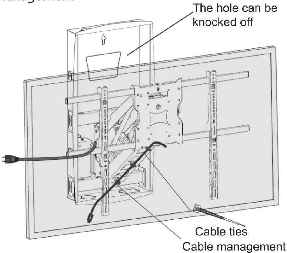
Use the integrated cable management clips on the arms to route cables to the back or side of the TV. Use cable ties where needed to keep the cables tidy and out of the way.
22
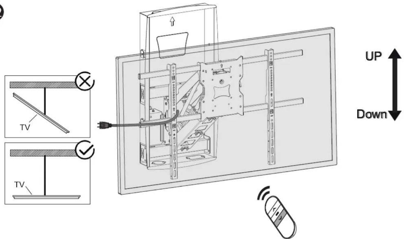
WARNING: Before raising the mount swivel the TV back until it is parallel to the wall. If the TV is angled toward the wall when raising it may impact the wall and cause damage to the TV or the mount. Ensure cables and other potential obstructions are always out of the way and will not get caught in moving components. Ensure adequate clearance between the top of the TV and the ceiling.
Visit us at www.mount-it.com for product registration and warranty information.
Our US based customer service team is standing by to answer any questions you have about your Mount-It! product.
Available by phone Monday - Friday from 8:00am to 4:00pm PST.
Chat live with an agent on our website!

support@mount-it.com

(855) 925-5668

www.mount-it.com
- Recessed Motorized Fireplace TV Mount
- MOUNT-IT!
- INSTALLATION INSTRUCTIONS
- Mount and Accessories
- TV Mounting Hardware
- Wall Mounting Hardware
- Required Tools (Not Included)
- Select TV Bolts
- A-G Select Bolts
- Select TV Spacers
- Select Spacers
- TV Compatibility :
- Remote Control Operation
- Control Unit Specifications
- Installation
- Mandatory Installation Requirements (Locate the Studs)
- Insert the Recessed Box
- Secure the Recessed Box
- Insert the Motorized Arm
- Extend the Arm Supports
- Install the Lag Screws
- Locate the Power Cable Remove 9e Cover from
- Connect the Power
- Lower the Arm
- Install the Control Unit
- Install the VESA Plate
- Secure the VESA Plate
- a: Attaching the TV to the VESA Arms For TVs with VESA Patterns 300x200-600x500.
- 15b: Attaching the TV to the VESA Plate
- Hang the TV on the Motorized Arm
- Securing The TV On The Mount
- Leveling Adjustment -5° - +5°
- Tilt Adjustment -5° - + 10°
- Swivel Adjustment -30° - +30°
- Cable Management
- 22
Brand : Mount-It!
Model : MI-302
Category : Flat Screen Mount