
AP902 - Receiver ATEN - Free user manual and instructions
Find the device manual for free AP902 ATEN in PDF.


| Product Type | Receiver (Wireless HDMI) |
| Brand | ATEN |
| Model | AP902 |
| Dimensions (W x D x H) | 125 mm x 80 mm x 25 mm |
| Weight | 150 g |
| Power Input | 5V DC, 2A |
| Video Resolution | Up to 1920 x 1080 @ 60Hz |
| Audio Support | Stereo LPCM |
| Wireless Range | Up to 30 m (line of sight) |
| Transmission Frequency | 5 GHz |
| Input Port | HDMI (receiver) |
| Output Port | HDMI |
| LED Indicators | Power, Signal |
| Operating Temperature | 0°C to 40°C |
| Storage Temperature | -20°C to 60°C |
| Cleaning | Wipe with dry cloth; avoid liquids |
| Safety Precautions | Do not expose to rain or moisture |
| Spare Parts Availability | Contact ATEN support |
| Warranty | 2 years |
| Compliance | CE, FCC |
Frequently Asked Questions - AP902 ATEN
User questions about AP902 ATEN
0 question about this device. Answer the ones you know or ask your own.
Ask a new question about this device
Download the instructions for your Receiver in PDF format for free! Find your manual AP902 - ATEN and take your electronic device back in hand. On this page are published all the documents necessary for the use of your device. AP902 by ATEN.
USER MANUAL AP902 ATEN
AP206 / AP212 Power Amplifier with DSP AP901 / AP902 Expansion Card for AP2 Series User Manual
Compliance Statements
FEDERAL COMMUNICATIONS COMMISSION INTERFERENCE STATEMENT
This equipment has been tested and found to comply with the limits for a Class B digital service, pursuant to Part 15 of the FCC rules. These limits are designed to provide reasonable protection against harmful interference in a residential installation. Any changes or modifications made to this equipment may void the user's authority to operate this equipment. This equipment generates, uses, and can radiate radio frequency energy. If not installed and used in accordance with the instructions, may cause harmful interference to radio communications. However, there is no guarantee that interference will not occur in a particular installation. If this equipment does cause harmful interference to radio or television reception, which can be determined by turning the equipment off and on, the user is encouraged to try to correct the interference by one or more of the following measures:
◆ Reorient or relocate the receiving antenna.
- Increase the separation between the equipment and receiver.
- Connect the equipment into an outlet on a circuit different from that to which the receiver is connected.
Consult the dealer or an experienced radio/TV technician for help.
The device complies with Part 15 of the FCC Rules. Operation is subject to the following two conditions: (1) this device may not cause harmful interference, and (2) this device must accept any interference received, including interference that may cause undesired operation.
FCC Caution: Any changes or modifications not expressly approved by the party responsible for compliance could void the user's authority to operate this equipment.

KCC Statement
Industry Canada Statement
This Class B digital apparatus complies with Canadian ICES-003.
CAN ICES-003 (B) / NMB-003 (B)
Trademark Statement
Audinate®, the Audinate logo and Dante are trademarks of Audinate Pty Ltd. https://www.audinate.com/legal/patents-and-trademarks

ENERGY STAR Certification

This device complies with the ENERGY STAR international standard for energy efficient products.
It automatically enters into standby mode when no input signal is detected for 25 minutes in order to save power while not in use.
In addition, a highly efficient amplifier circuitry design has been adopted to reduce energy
consumption while the device is in use.
RoHS
This product is RoHS compliant.
User Information
Online Registration
Be sure to register your product at our online support center:
International http://eservice.aten.com
Telephone Support
For telephone support, call this number:
| International 886-2-86 | 92-6959 |
| China 86-400-810-0-8 | 10 |
| Japan 81-3-5615-5811 | |
| Korea 82-2-467-6789 | |
| North America 1-888- | 999-ATEN ext 4988 |
| 1-949-428-1111 |
User Notice
All information, documentation, and specifications contained in this manual are subject to change without prior notification by the manufacturer. The manufacturer makes no representations or warranties, either expressed or implied, with respect to the contents hereof and specifically disclaims any warranties as to merchantability or fitness for any particular purpose. Any of the manufacturer's software described in this manual is sold or licensed as is. Should the programs prove defective following their purchase, the buyer (and not the manufacturer, its distributor, or its dealer), assumes the entire cost of all necessary servicing, repair and any incidental or consequential damages resulting from any defect in the software.
The manufacturer of this system is not responsible for any radio and/or TV interference caused by unauthorized modifications to this device. It is the responsibility of the user to correct such interference.
The manufacturer is not responsible for any damage incurred in the operation of this system if the correct operational voltage setting was not selected prior to operation. PLEASE VERIFY THAT THE VOLTAGE SETTING IS CORRECT BEFORE USE.
Product Information
For information about all ATEN products and how they can help you connect without limits, visit ATEN on the Web or contact an ATEN Authorized Reseller.
Visit ATEN on the Web for a list of locations and telephone numbers:
| International http://www.aten.com |
| North America http://www.aten-usa.com |
Package Contents
Check to make sure that all the components are in working order. If you encounter any problem, please contact your dealer.
◆ 1 AP206 / AP212 Power Amplifier with DSP
◆ 1 rack mount / surface mount kit
◆ 1 foot pad set (4 pcs)
◆ 2 3-pin Euroblock connectors with strain relief (3.5mm)
◆ 1 5-pin Euroblock connector with strain relief (3.5mm)
◆ 1 4-pin Euroblock connector with screw lock (5.08mm)
◆ 1 3-pin Euroblock connector (3.5mm)
◆ 1 power cord
◆ 1 user instructions
Table of Contents
Compliance Statements ...... ii
User Information iv
Online Registration iv
Telephone Support .....iv
User Notice....iv
Product Information ...... v
Package Contents.... v
Table of Contents ......vi
About this Manual ......viii
Conventions ix
1. Introduction
Overview....1
Features 2
Planning the Installation .... 3
Requirements....3
Components 4
Front View 4
Rear View 4
LED Status 6
2. Hardware Setup
Connecting the AP206 / AP212 Unit 7
Mounting the AP206 / AP212 Unit 10
Rack Mount 10
Surface Mount 12
Expansion Card 14
Hardware Overview 15
AP901 15
AP902 16
Configuring Audio Gain on AP902 17
Installing / Removing the Expansion Card 19
Installing 19
Removing 20
3. Operation
Browser Web Control 21
DHCP-assigned IP Address. 21
Login 23
DSP Configuration 25
Speaker Out Processing....26
Input Signal Control 28
Speaker Selector 29
Delay Configuration 30
Equalizer Configuration....31
Limiter Configuration.... 33
Line Out Processing 35
Delay Configuration 37
Low-pass Filter Configuration 38
Preset Management 39
Save a New Preset 39
Apply an Existing Preset 40
Edit an Existing Preset 40
System Settings 41
General Tab 43
Local Address 43
IP Settings....44
Firmware Upgrade 44
Other Settings....45
Web Settings 48
Account Lockout Policy 49
Preset Tab. 50
Test Tab. 53
Dashboard Tab....54
Appendix
Safety Instructions....55
General 55
Rack Mounting 57
Technical Support 58
International 58
North America 58
Specifications 59
AP206 59
AP212 61
AP901 63
AP902 64
ATEN Standard Warranty Policy 65
Limited Hardware Warranty 65
About this Manual
This user manual is provided to help you get the most from the AP206 / AP212 unit. It covers all aspects of installation, configuration, and operation. Devices and accessories covered in this manual include:
| Models Product Names |
| AP206 2 × 60W Power Amplifier with DSP |
| AP212 2 × 120W Power Amplifier with DSP |
| AP901 2-CH Dante Expansion Card for AP Series |
| AP902 2-CH Mic/Line Pre-AMP Expansion Card for AP Series |
An overview of the information found in the manual is provided below.
Chapter 1, Introduction introduces you to the AP206 (2 × 60W) / AP212 (2 × 120W) Power Amplifier with DSP. Its purpose, features, installation considerations, and panel components are presented and described.
Chapter 2, Hardware Setup describes the steps that are necessary to quickly and safely set up your installation.
Chapter 3, Operation specifies how to process the web control and configuration for the unit through the Ethernet connection
Appendix, provides a list of safety instructions and precautions, contact information for ATEN technical support, product specifications, and other technical information.
Note:
- Read this manual thoroughly and follow the installation and operation procedures carefully to prevent any damage to the unit or any connected devices.
This product may be updated, with features and functions added, improved or removed since the release of this manual. For an up-to-date user manual, visit http://www.aten.com/global/en/
Conventions
This manual uses the following conventions:
MonospacedIndicates text that you should key in.
[] Indicates keys you should press. For example, [Enter] means to press the Enter key. If keys need to be chorded, they appear together in the same bracket with a plus sign between them: [Ctrl+Alt].
- Numbered lists represent procedures with sequential steps.
◆ Bullet lists provide information, but do not involve sequential steps.
Indicates selecting the option (on a menu or dialog box, for example), that comes next. For example, Start > Run means to open the Start menu, and then select Run.

Indicates critical information.
Chapter 1
Introduction
Overview
The AP206 / AP212 Power Amplifier with DSP is a 2-channel power amplifier with built-in DSP. The AP206 is 60W per channel while the AP212 is 120W per channel. The AP206 / AP212 receives balanced or unbalanced line level audio signal to drive 4 ohms or 70V/100V (under bridge mode only) speakers for public address applications. The AP206 / AP212 unit is able to compatible with Dante audio when the AP901 Dante expansion card is installed in the expansion slot. The expansion slot could be used for another pre-amp module, AP902, which obtains 2-channel Mic/Line inputs. The AP206 / AP212 power amplifier is compatible with ATEN VK system through RS-232 and Etherent, and user can configure the entire system by built-in WebGUI.
Features
◆ 2 × 60W (AP206) / 2 × 120W (AP212) Class D amplifier with Hi-Z and Low-Z output
♦ Optional Dante expansion card (AP901)
♦ Optional 2-channel Mic/Line preamp expansion card (AP902)
Built-in DSP (digital signal processing): Includes speaker selector, 5-band output EQ, limiter, and delay
◆ DSP configuration and firmware update though LAN
◆ Supports up to 20 DSP presets
- Meets requirement of Energy Star that power saving mode and auto standby mode are supported
◆ Supportsthermal protection
◆ Supports ATEN control system via RS-232 serial port and Ethernet
◆ Universal power supply with PFC
◆ Ground lift switch for eliminating hum noise caused by ground loops
◆ Advanced protection circuits for protect the amplifier and loads (speakers) against shorted outputs, Amp over/under-voltage, and output over current
♦ Flexible installation including rack mount and surface mount
◆ Fanless chassis design
Planning the Installation
Requirements
Prepare the following before installing the AP206 / AP212 unit:
◆ 1 set of ceiling loudspeakers
◆ 1 or more audio source devices
Components
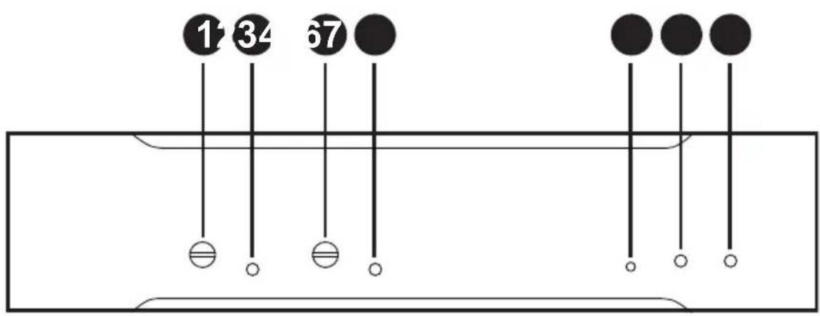
Front View
Rear View
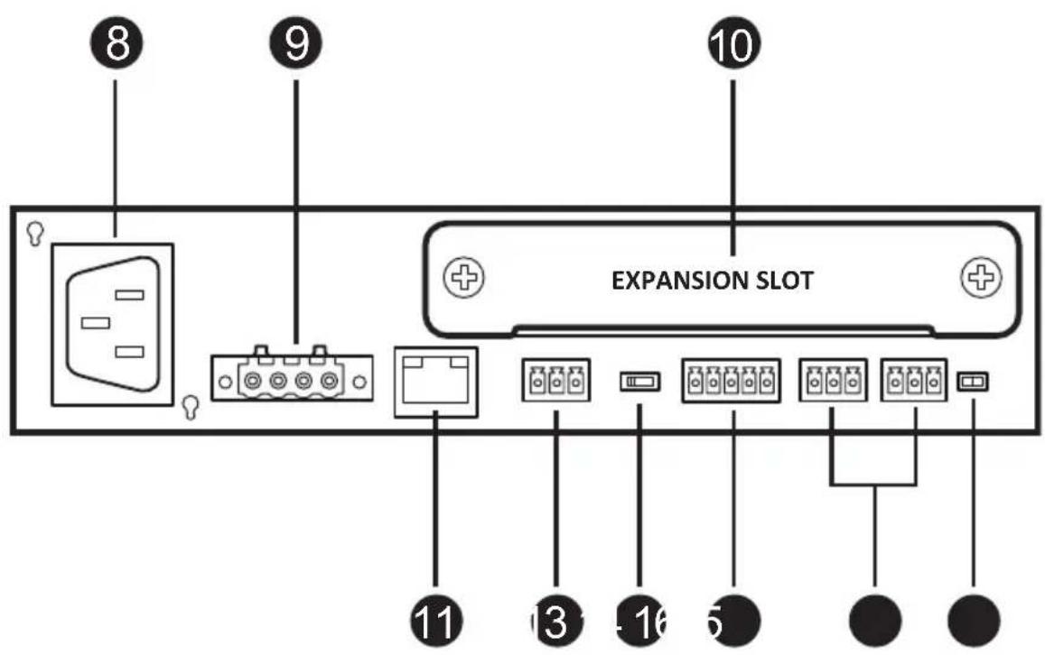
| No. | Component Description | |
| 1 | volume control for channel A Adjusts the audio output volume of channel A. | |
| 2 | signal / clip LED for channel A | Lights to indicate the audio signal status of channel A. Refer to LED Status, page 6 for details. |
| 3 | volume control for channel B Adjusts the audio output volume of channel B. | |
| No. | Component | Description |
| 4 | signal / clip LED for channel B | Lights to indicate the audio signal status of channel B. Refer to LED Status, page 6 for details. |
| 5 | reset button Press this button to reset the MCU of the unit. | |
| 6 | standby LED Lights to indicate the unit is in standby mode.Refer to LED Status, page 6 for details. | |
| 7 | power LED Lights to indicate the unit is powered on. Refer to LED Status, page 6 for details. | |
| 8 | power socket Connects to the power cord. | |
| 9 | speaker out(4-pin Euroblock connector) | Connects to a set of passive speakers such as AS104 / AS106 / AS108. |
| 10 | expansion slot Installs the expansion card, such as AP901 /AP902, into the expansion slot for flexible and expandable connectivity. | |
| 11 | LAN port Connects to a network switch or a PC. | |
| 12 | RS-232 serial port Connects to an ATEN Control Pad. | |
| 13 | impedance switch Adjusts the impedance between 4Ω, 70V, and 100V. | |
| 14 | audio line output channel(5-pin Euroblock connector) | Connects to an active subwoofer or other audio equipment. |
| 15 | audio line input channels(3-pin Euroblock connectors) | Connects to your audio sources. |
| 16 | ground / lift switch Switches to lift to eliminate hum noise from dirty AC electric power circuit. | |
LED Status
You can find the unit's LEDs on the front panel as illustrated below. See the table below for details on the LED indication.
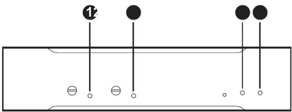
| No. | LED Indication Description | ||
| 1 | signal / clip LED for channel A | lights green The | audio signal strength is over -53dBFS. |
| lights red The au | dio signal strength reaches the hard-clipping limit (-3dBFS). | ||
| off There is no | audio signal. | ||
| 2 | signal / clip LED for channel B | lights green The | audio signal strength is over -53dBFS. |
| lights red The au | dio signal strength reaches the hard-clipping limit (-3dBFS). | ||
| off There is no | audio signal. | ||
| 3 | standby LED lights amber | The unit is in | standby mode and audio strength is less than -24dBu. |
| blinks amber The | unit is in overheat protection mode. | ||
| off The unit is running and not in the standby mode. | |||
| 4 | power LED lights green | The unit is powered on. | |
| blinks green Firmware upgrade of the unit is in process. | |||
| off The unit is powered off. | |||
Chapter 2
Hardware Setup

-
Please review the safety information regarding the placement of this device in Safety Instructions, page 55.
-
Do not power on the AP206 / AP212 until all the necessary hardware is connected.
Connecting the AP206 / AP212 Unit
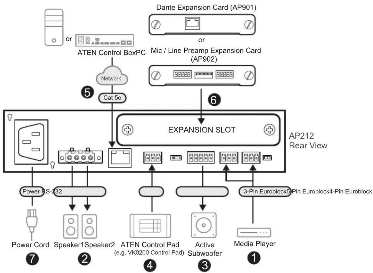
Follow the steps below to connect the AP206 / AP212 to audio source devices, a set of loud speakers, and an ATEN controller.
flowchart
graph TD
    A["Power RS-232"] --> B["Speaker1Speaker2"]
    B --> C["ATEN Control Pad (e.g. VK0200 Control Pad)"]
    C --> D["Active Subwoofer"]
    D --> E["3-Pin Euroblock5-Pin Euroblock4-Pin Euroblock"]
    E --> F["Media Player"]
    G["Dante Expansion Card (AP901)"] --> H["ATEN Control BoxPC"]
    I["Mic / Line Preamp Expansion Card (AP902)"] --> J["Cat 5e"]
    J --> K["EXPANSION SLOT"]
    K --> L["AP212 Rear View"]
    M["Power Cord"] --> N["Speaker1Speaker2"]
    O["Radio"] --> P["ATEN Control Pad"]
    Q["Radio"] --> R["Active Subwoofer"]
    S["Radio"] --> T["3-Pin Euroblock5-Pin Euroblock4-Pin Euroblock"]
Note: Make sure all the equipment you are connecting to the unit is turned off and disconnected from the power source.
- Connect your audio sources to the audio input channels.
- Connect the speakers to the unit's speaker output.
Note:
- To avoid damaging the amplifier, please connect the wires to your speakers first, and then connect the other end of the wire to the speaker output channels using the supplied 4-pin Euroblock connector with screw lock (5.08 mm).
-
Keep the unit and its small parts such as 4-Pin Euroblock connector out of the reach of children. Children can choke or suffocate on the released small parts through detachment or breakage.
-
Connect the subwoofer or other audio equipment to the unit.
-
(Optional) To control the unit using an ATEN Control Pad, connect the Control Pad to the unit's RS-232 port.
-
(Optional) Use the LAN port for firmware upgrades, DSP configuration, or remote management (using a hardware controller).
-
To control the unit using a hardware controller through the Ethernet, e.g. an ATEN Control Box, connect the LAN port to a network switch.
- To upgrade firmware, configure DSP settings (via the web console), or manage the unit, connect the LAN port to a PC.
Note: The default IP address is 192.168.0.60. Use the default login credentials administrator and password upon first login.
- (Optional) To connect the unit to the Dante network or additional mic/ line level output device(s), install the Dante expansion card (AP901) or mic/line preamp expansion card (AP902) to the expansion slot in advanced.
Note:
- AP901 and AP902 are sold separately.
-
Refer to Installing / Removing the Expansion Card, page 19 for how to install / remove the expansion card.
-
Connect the supplied power cord to the unit's power socket after powering on all other audio equipment. The unit's power LED lights green to indicate the unit is powered on.
Note: The AP206 / AP212 unit enters network standby mode once it is powered on. To wake up the unit, feed a audio signal whose strength is more than -24dBu, or log in to the web console to activate the unit.
- Adjust the volume from the unit's front panel.
Mounting the AP206 / AP212 Unit
Note: The foot pad set is used only when placing the unit on a flat surface to prevent the unit from slipping. Do not attach the foot pads to the unit if you'd like to mount the unit onto a system rack or secure it on a flat surface.
Rack Mount
To mount the unit onto a standard 19" rack:
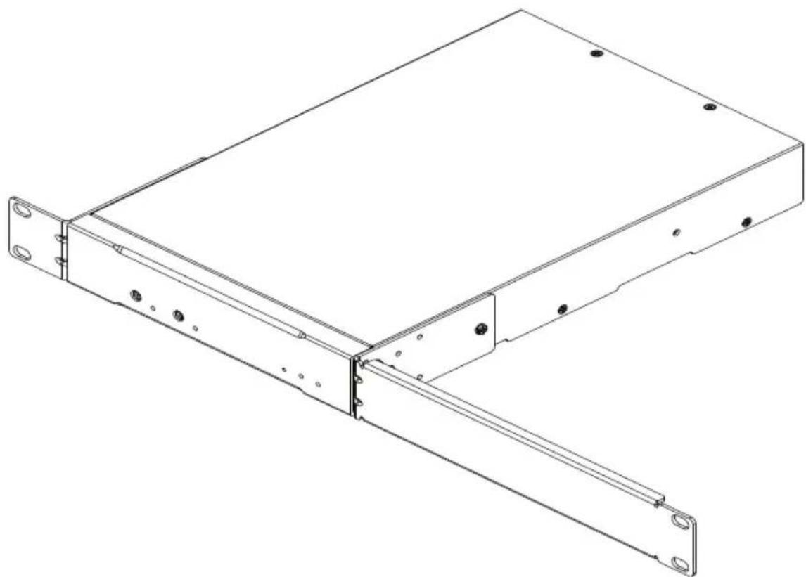
To mount a single unit, attach the two mounting brackets onto the sides of the unit with six M3 indented hex washer head screws provided. Align the mounting brackets' screw holes with that of the front of the rack, and secure the unit onto the rack using self-supplied screws.
natural_image
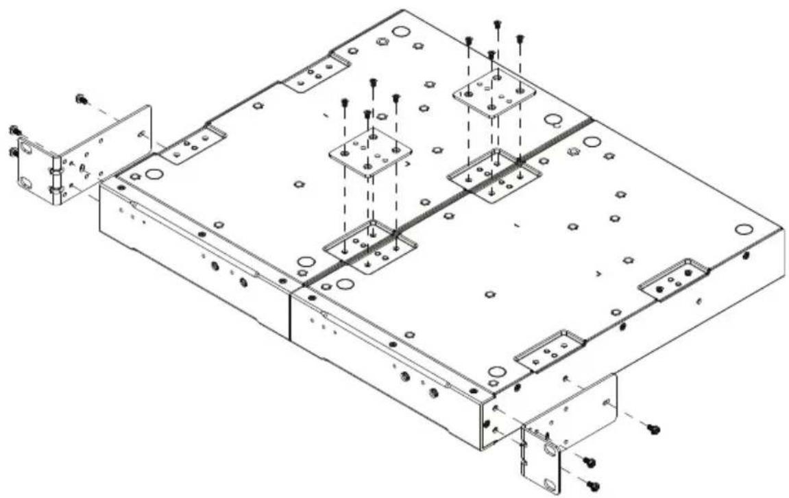
Technical line drawing of a mechanical assembly with mounting flanges and a rectangular housing (no text or symbols)- To mount two units, screw the two line brackets onto the bottom side of the two units with eight M3 flat head screws. Attach the mounting brackets onto the units with six M3 indented hex washer head screws provided. Align the mounting brackets' screw holes with that of the front of the rack, and use self-supplied screws to secure the unit onto the system rack.
natural_image
Technical line drawing of a mechanical assembly with mounting brackets and mounting holes (no text or symbols)Surface Mount
To secure the unit on a flat surface:
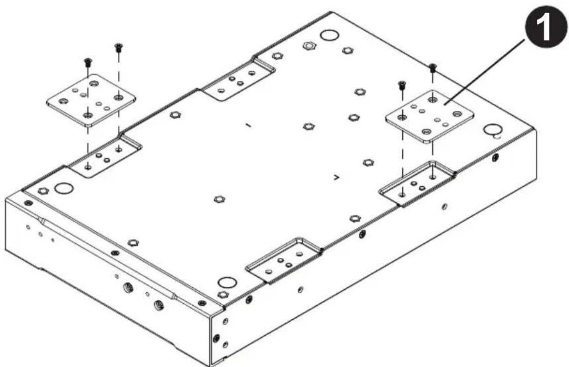
- Use four M3 flat head screws to fasten the line brackets to the bottom of the unit.
natural_image
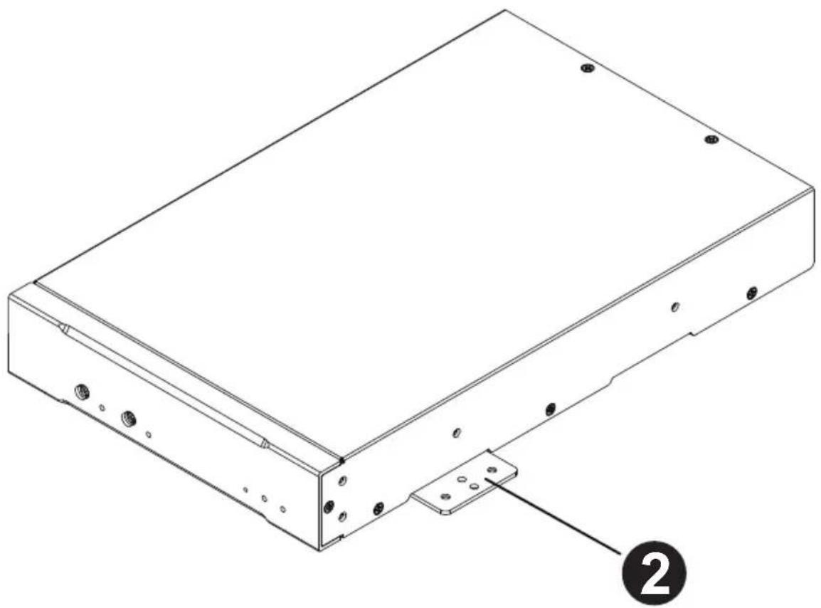
Technical line drawing of a mechanical assembly with mounting holes and mounting brackets (no text or symbols)- Place the unit on a flat surface, such as a desk, and secure the unit on the surface with self-supplied screws that fit 3 mm screw hole aperture.
natural_image
Technical line drawing of a rectangular electronic device with mounting bracket and labeled component (no text or symbols beyond basic diagram)Expansion Card
The expansion cards listed below are dedicated for use with ATEN's AP DSP Power Amplifier series:
Note: The expansion cards are sold separately. Please contact your ATEN dealer or go to ATEN website for available accessories and product information.
◆ AP901 2-CH Dante Expansion Card for AP Series
- Allows AP power amplifiers to receive 2 inputs of highquality, low-latency digital audio via Dante AoIP solution
- Enables AP power amplifiers to easily integrate with Dante-enabled devices, such as digital mixers, processors, and media players
◆ Supports 24-bit and sampling rates of 44.1k and 48kHz - Compatible with Dante Controller software to achieve streamlined workflow
Easy to be installed into the AP power amplifiers' expansion slot
◆ Firmware upgradable via Dante LAN
◆ AP902 2-CH Mic/Line Pre-AMP Expansion Card for AP Series
- Provides AP power amplifiers with dual-channel inputs for easier integration with balanced / unbalanced audio signals at mic / line level
- Adjustable gain level – handles various strength levels of input sources
- Preamp designed to lower the noise floor and improve the dynamic range for high-quality sound performance
Easy to be installed into the AP power amplifiers' expansion slot
Hardware Overview
AP901
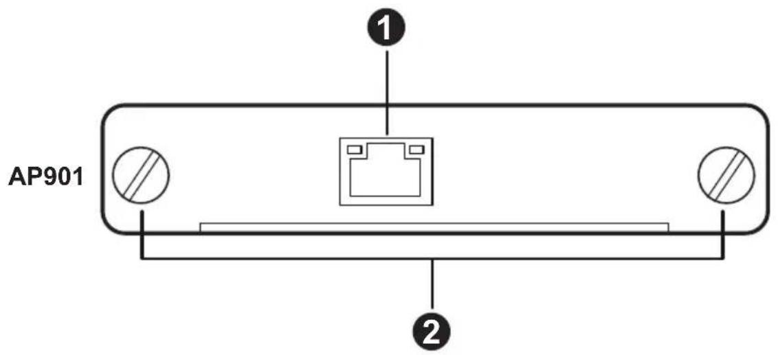
| No. | Component Description | |
| 1 | Dante link port | Use an Ethernet cable to connect the Dante link port to a network switch. It is strongly recommended that you use a shielded Cat 5e cable (or higher) for better network connectivity. |
| 2 | screws Fasten the expansion card to the slot of the AP DSP Power Amplifier using the screws. Tighten the screw by turning it clockwise while loosen the screw by turning it counterclockwise. | |
AP902
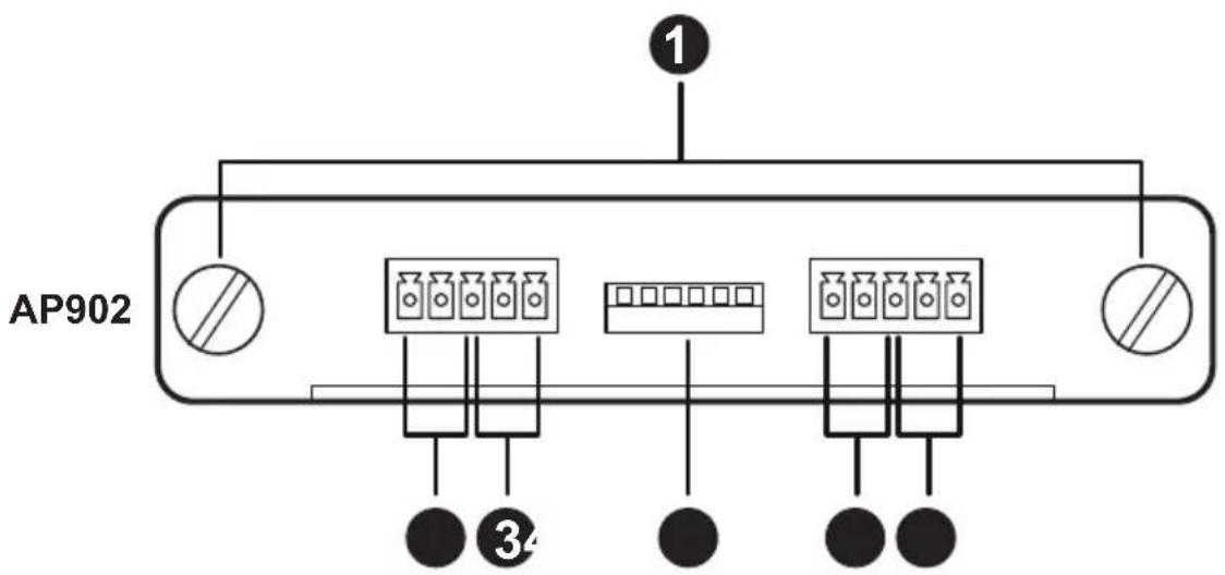
| No. | Component Description |
| 1 | screws Fasten the expansion card to the slot of the AP DSP Power Amplifier using the screws. Tighten the screw by turning it clockwise while loosen the screw by turning it counterclockwise. |
| 2 | line input for channel 2 |
| 3 | mic input for channel 2 |
| 4 | gain control switch Switch on or off the pole(s) to adjust the audio gain level. |
| 5 | line input for channel 1 |
| 6 | mic input for channel 1 |
| Note: 1. To prevent device damage, do not feed a line level signal to mic input channel.2. Do not connect Mic/Line in the same channel at the same time. | |
Configuring Audio Gain on AP902
To adjust the audio gain level, switch on or off the pole(s) as the following table shows:
Note: Pole 1 to pole 3 are for channel 2 while pole 4 to pole 6 are for channel 1.
| Gain Level Position of Individual Switches | |
| -6dB | 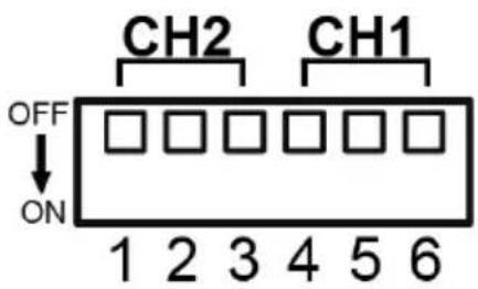 |
| 0dB | 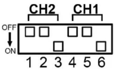 |
| +6dB | 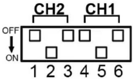 |
| +12dB | 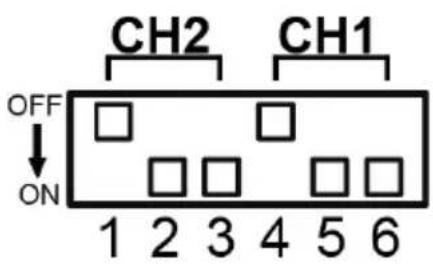 |
| +18dB | 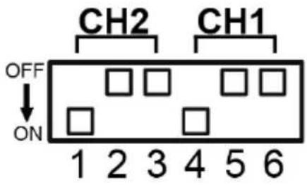 |
| +24dB | 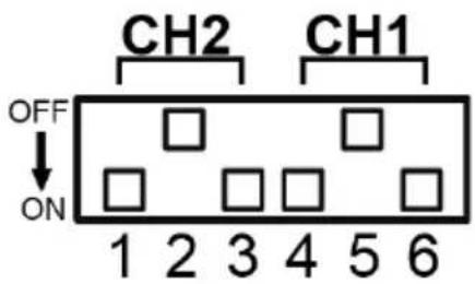 |
| +30dB | 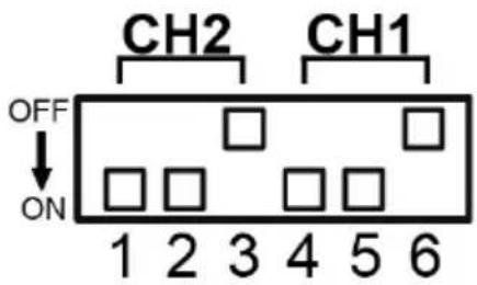 |
| +36dB | 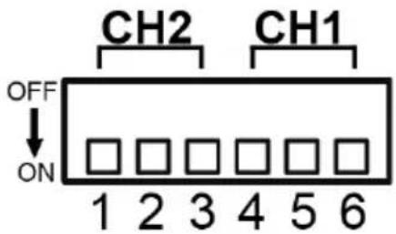 |
Installing / Removing the Expansion Card
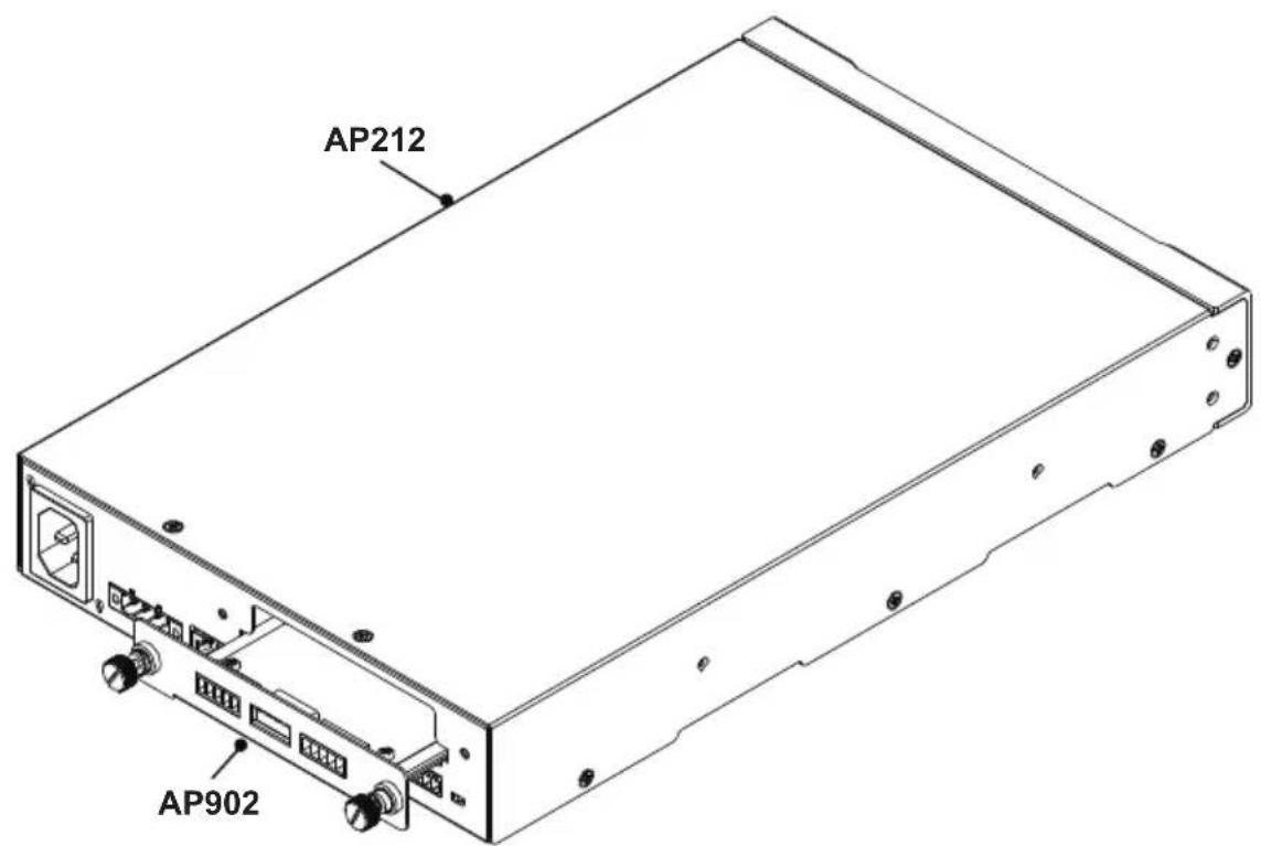
Make sure that you turn off the AP206/AP212 power amplifier and disconnect the unit from the power source before installing or removing the expansion card.
Installing
To install the expansion card into the AP206/AP212 power amplifier:
-
Remove the expansion slot plate on the rear side of the AP206/AP212 power amplifier.
-
Insert the expansion card into the amplifier's expansion slot.
Note: Give a little push to get the expansion card fully seated in the slot.
- Apply force to each screw head till it is in place, and then tighten the screw by turning it clockwise.
Removing
Note: For safety purpose, please power off the AP206/AP212 power amplifier and then wait for 50 seconds before removing the expansion card.
To remove the expansion card:
-
Alternately loosen each screw.
-
Hold the two screws and then gently pull out the expansion card.
-
Use the expansion slot plate to cover the blank slot, and secure it with the screws.
Browser Web Control
The AP206 / AP212 power amplifier offers the web control and configuration through the Ethernet connection. The default IP address of the unit's web console is 192.168.0.60 without DHCP environment. If you connect the AP206 / AP212 unit to a router, use the IP address that DHCP server allocates.
DHCP-assigned IP Address
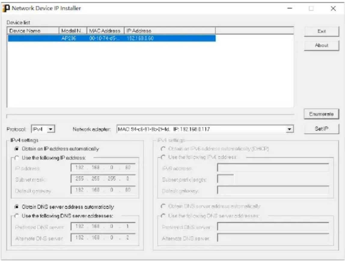
To get the DHCP-assign IP address, do the followings:
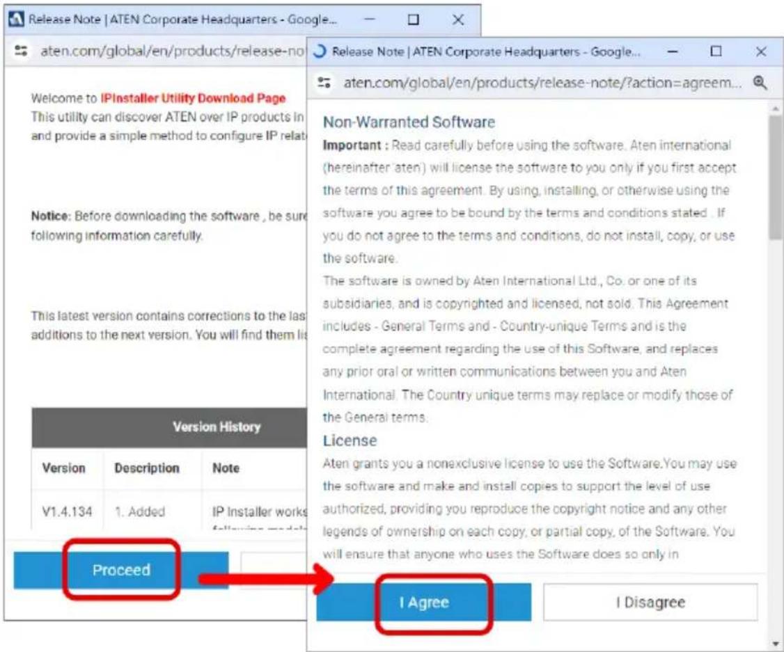
- Download the IP Installer from the Support and Download tab of the product page.
-
Unzip the .zip file of the IP Installer and then run the .exe file.
-
Obtain the DHCP-assigned IP address of the unit from the Device List, and use this IP address to access the unit's web console.
Login
To control the unit from a web control:
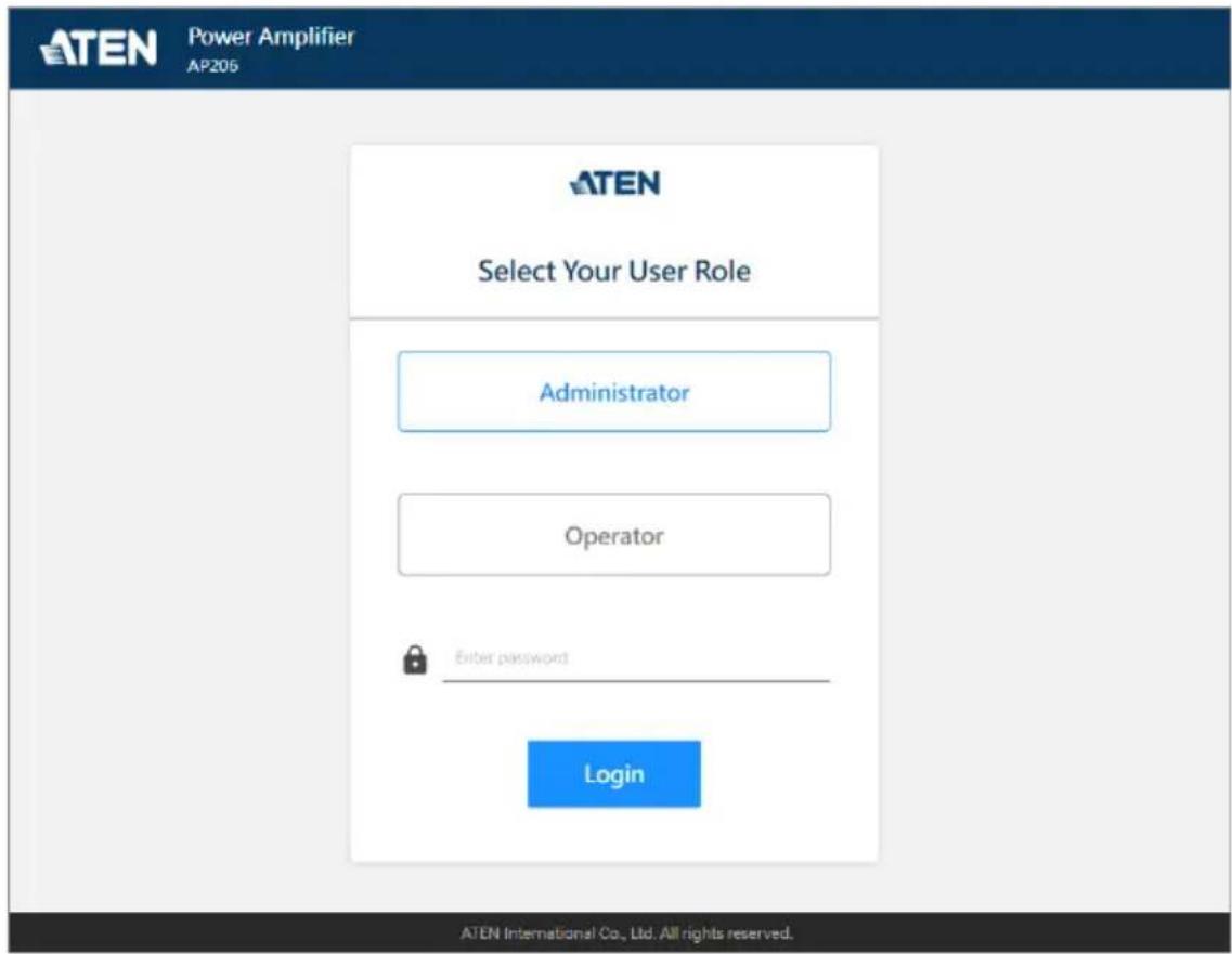
- Start up the supported web browser, and then input the unit's IP address into the address bar.
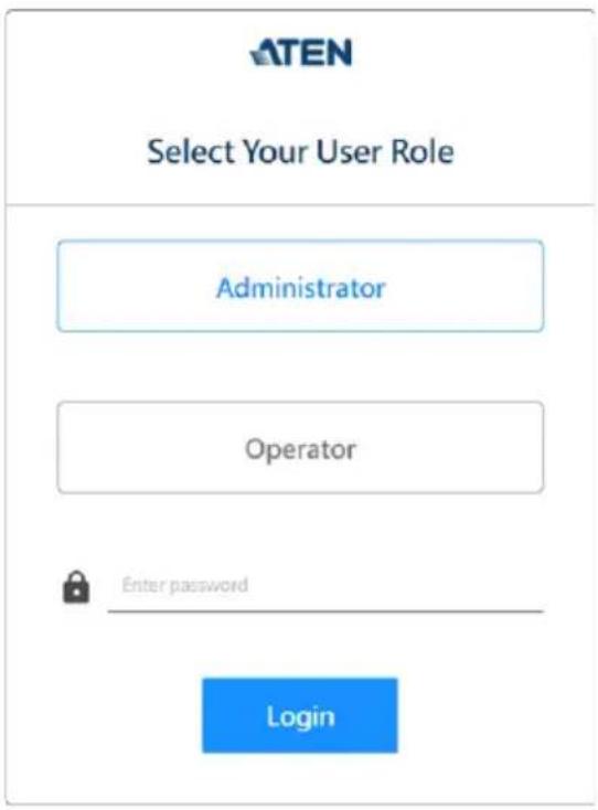
- The login page shows up. Upon first login, select Administrator as the user role type, and use the default password, password.
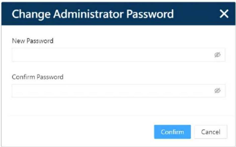
- It requires to change the password for Administrator. Follow the on-screen instructions to complete.
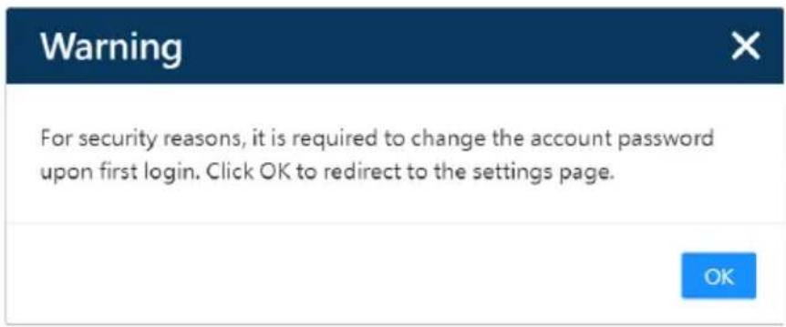
a) Enter the new password for Administrator, and confirm by entering the password again. Click on the Confirm button to continue.
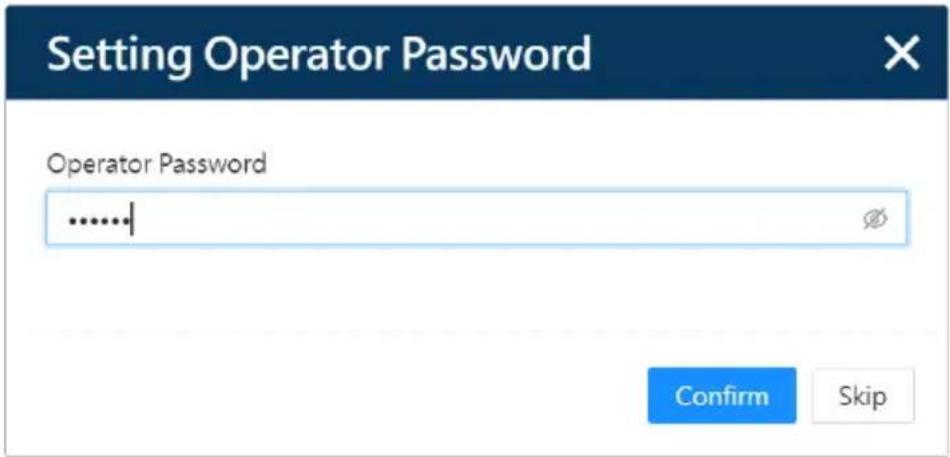
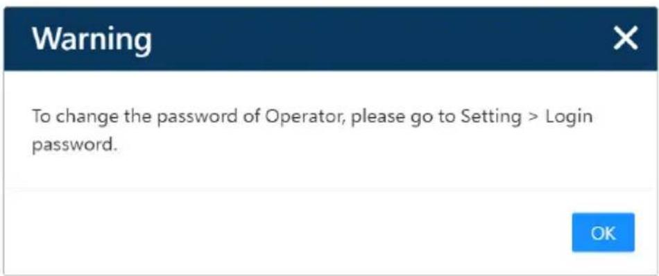
b) Change the password for Operator. You can skip this steps and change the Operator's password later on.
c) After successfully changed the password, you will be redirected to the login page again. Use the new password to log in to the unit's web console.
DSP Configuration
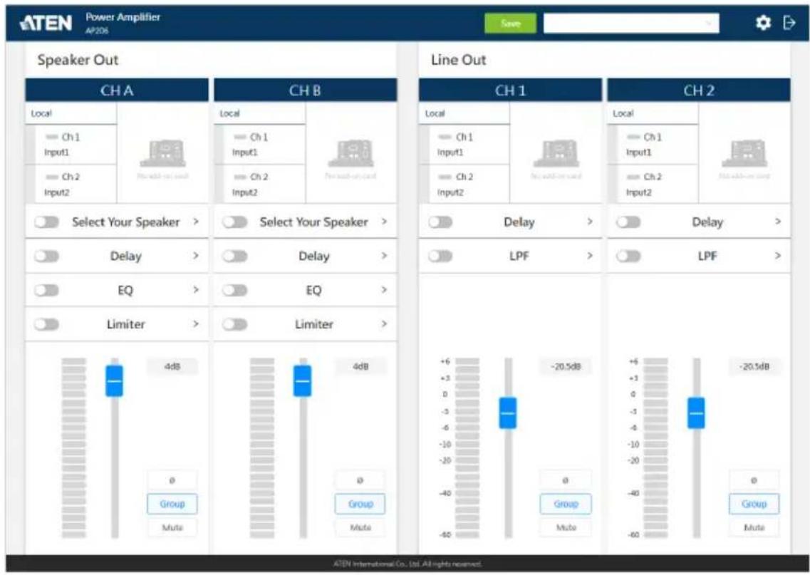
Digital Signal Processing (DSP) performs sound manipulation using the algorithms to filter, equalize, limit, and enhance the audio signal. After logging in or waking up the unit from the standby mode, you will enter the DSP configuration screen as illustrated below:
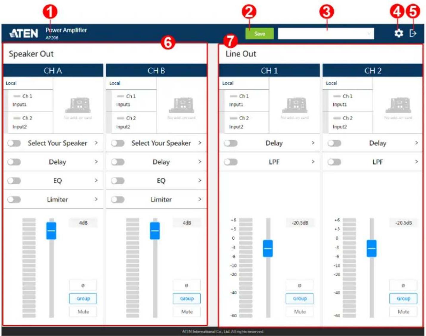
| No. Item Description | |
| 1 model name The model name of the connected unit | |
| 2 save button A button for saving the current configurations to be a preset | |
| 3 preset menu A drop-down menu that contains all the saved preset(s) for user to choose to load the preset | |
| 4 settings button A button for switching to the system settings screenNote: This function button is only available for Administrator. | |
| No. | Item Description | |
| 5 exit | button A button for logging out the web console | |
| 6 speaker out operation area | The configuration panel that the speaker-level audio signals are manipulated | |
| 7 line | out operation area | The configuration panel that the line-level audio signals are processed |
Speaker Out Processing
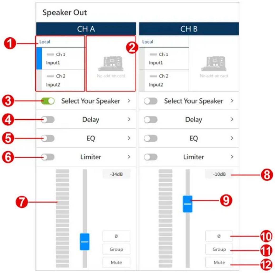
The speaker out operation panel offers the following settings for user to manipulate the speaker-level audio signals and output the processed audio signals to the speakers connected to the unit's speaker output channels.
| No. | Item Description | |
| 1 | input signal control area | In the input signal area, you can:◆ Click to select the audio signal from input channel(s). You can select multiple input channels at a time.◆ Rename the input channels.See Input Signal Control, page 28. |
| 2 | expansion card If you have | the expansion card installed on the unit,this area becomes available and offers the same functions as the input signal control area does. |
| 3 | speaker selector Click to select the speaker that connects to the speaker out channel. | |
| 4 | delay switch | Switch on or off to apply or withdraw the delay settings to the audio signal. Click on the function name to open the popup for further configurations. See Delay Configuration, page 30. |
| 5 | equalizer switch Switch on or off to apply or withdraw the EQ settings to the audio signal. Click on the function name to open the popup for further configurations. See Equalizer Configuration, page 31. | |
| 6 | limiter switch | Switch on or off to apply or withdraw the limiter settings to the audio signal. Click on the function to open the popup for further configuration. See Limiter Configuration, page 33. |
| 7 | signal level meter | Show the audio signal levels in decibels (dB). |
| 8 | channel fader level | Show the gain or attenuation level in number of the audio signal to be output. |
| 9 | channel fader | Adjust the gain or attenuation level of the audio signal to be output. Drag the fader to change the value in decibel. The volume value also displays in the channel fader level field next to the channel fader. |
| 10 | phase button | Click the button to invert the polarity of the phase.Disabling this function means that the phase polarity is normal. |
| 11 | fader group button | Enable the group function to add this channel to the linked channels to simultaneously control the volume levels. |
| 12 | mute button | Click on the mute button to enable or disable the mute function for this channel. |
Input Signal Control
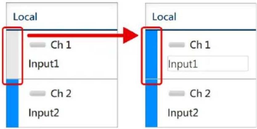
To select the input audio signal, click on the select bar of the channel you'd like to choose.
flowchart
graph LR
    A["Local"] --> B["Local"]
    A --> C["Ch 1"]
    A --> D["Input1"]
    A --> E["Ch 2"]
    A --> F["Input2"]
    B --> G["Ch 1"]
    B --> H["Input1"]
    B --> I["Ch 2"]
    B --> J["Input2"]
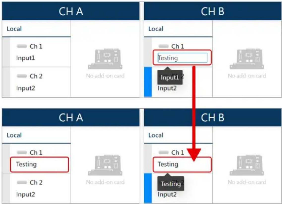
To rename the input channel, click on the name field to fill in the new name.
flowchart
graph TD
    subgraph_CH_A["CH A"]
        A1["Local"] --> A2["Ch 1 Input1"]
        A2 --> A3["Ch 2 Input2"]
    end
    subgraph_CH_B["CH B"]
        B1["Local"] --> B2["Ch 1 Testing"]
        B2 --> B3["Input1 2 Input2"]
        B3 --> B4["No add-on card"]
    end
    CH_A --> CH_B
    CH_A --> CH_B
    CH_B --> CH_A
    CH_B --> CH_B
    CH_A --> CH_B
    CH_B --> CH_A
    style CH_A fill:#f9f,stroke:#333
    style CH_B fill:#bbf,stroke:#333
Speaker Selector
On the popup window, you can do the followings:
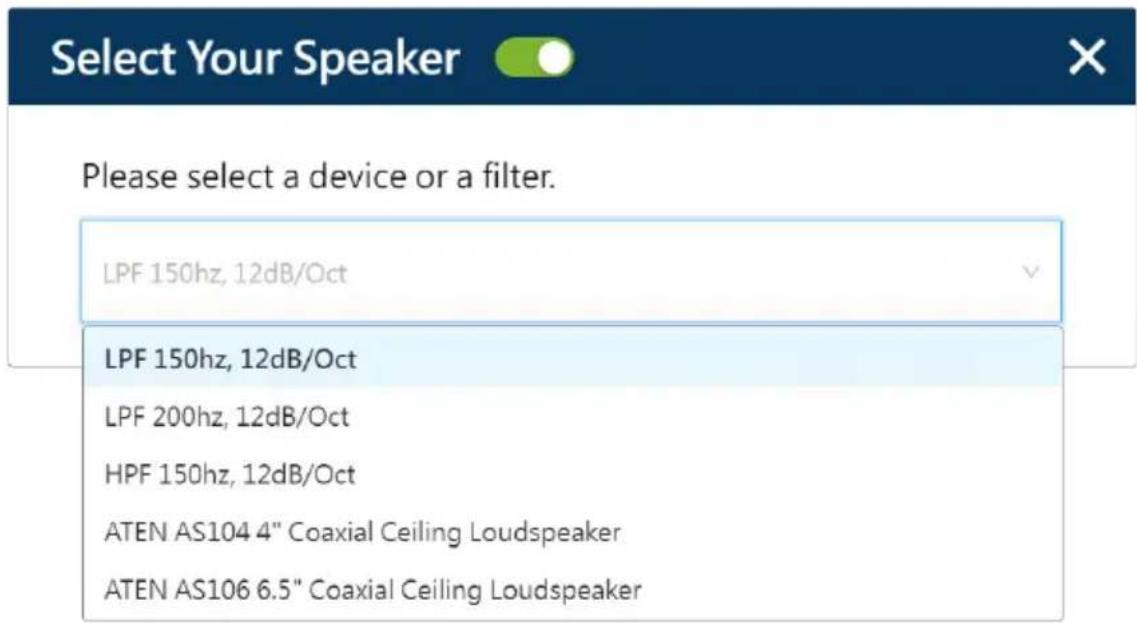
- Turn on the switch to enable the optimization of the audio signal to be output to the connected speaker.
- Select the filter to apply:
If this speaker output channel connects with an ATEN loudspeaker, directly select the model and the system will automatically apply the optimization.
If you use a self-supplied audio output device, select a filter that is suitable for your output device to apply.
| Filter Description | |
| LPF 150Hz, 12dB/Oct LPF | are often used with subwoofers. Choose between 150Hz and 200Hz based on your connected subwoofer, and apply the low pass filter to filter out the high-frequency sounds from an audio signal. |
| LPF 200Hz, 12dB/Oct | |
| HPF 150Hz, 12dB/Oct Apply the high pass filter to filter out the low-frequency content of the signal to increase the clarity and definition. | |
Delay Configuration
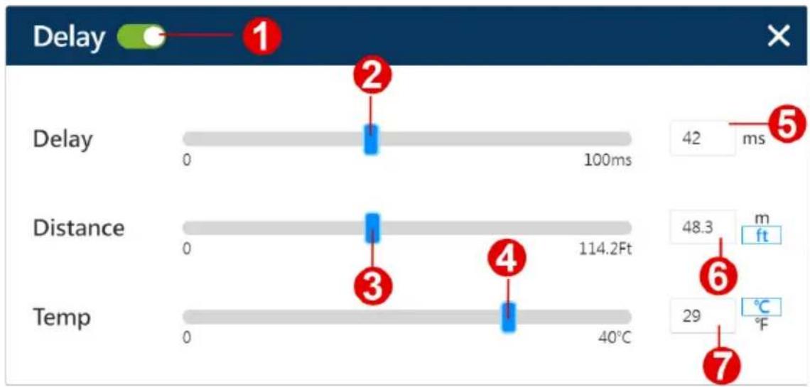
The delay settings helps to synchronize multiple sets of speakers and improve audio clarity.
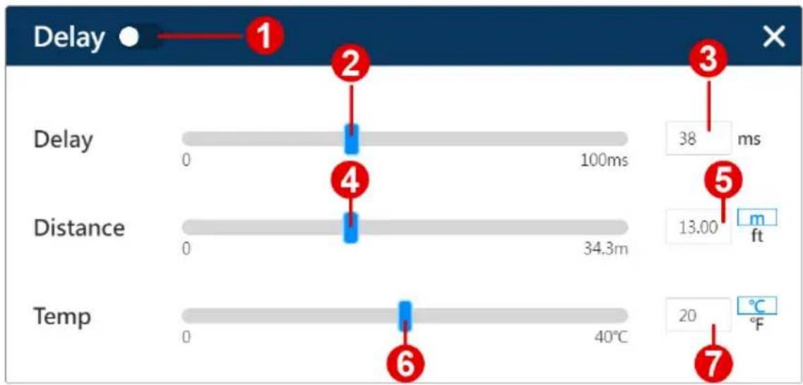
| No. | Item Description | |
| 1 | delay settings switch Turn | on / off the switch to apply / withdraw the delay settings. |
| 2 | delay time slider | Drag the slider to set the delay time in millisecond. The time value is also shown in the delay time value field next to the slider. |
| 3 | delay time value Show the | delay time value in millisecond. You can directly input the value to this field to change the delay time value. |
| 4 | distance slider Drag the slider to set the distance in feet or meters.The distance value is also shown in the distance value field next to the slider. | |
| 5 | distance value Show the distance in feet or meters. To change the value, do the followings:a) Input the value in the field.b) Click to select the unit of length between feet and meters. | |
| 6 | temperature slider Drag the slider to set the temperature in Celsius or Fahrenheit. The temperature value is also shown in the temperature value field next to the slider. | |
| 7 | temperature value Show the temperature in Celsius or Fahrenheit. To change the value, do the followings:a) Input the value in the field.b) Click to select the temperature scale between Celsius and Fahrenheit. | |
Equalizer Configuration
EQ (equalizer) is used to adjust the level of an audio signal at particular frequencies. To configure the frequency, click to select HPF (high-pass filter) shown in the EQ graph and then set by dragging the HPF or inputting the frequency value field. To configure the gain value and the Q factor, click to select between band 1, 2, 3, and 4 in the EQ graph to continue setting.
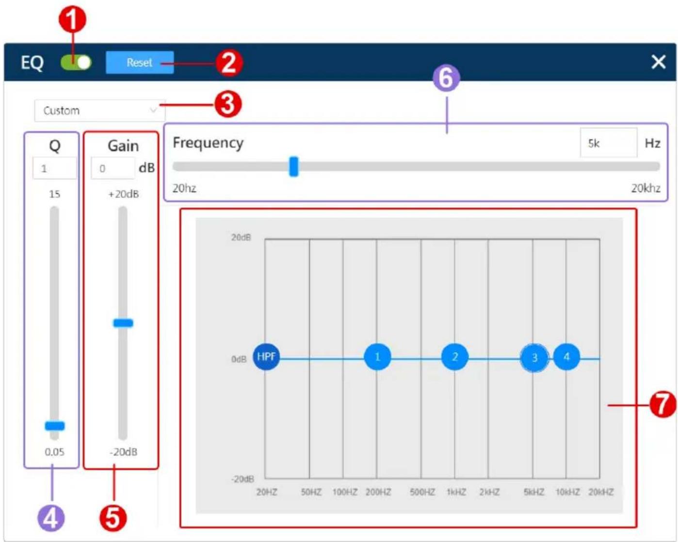
| No. | Item | Description | |
| 1 | E | Q | Switch it on to enable the equalizer to boost or suppress the audio frequency bands. |
| 2 reset button Click on the reset button to restore the EQ configurations to the default. | |||
C
| No. | Item Description | |
| 3 option menu Select the mode from the drop-down menu to apply the EQ settings. Please note that the EQ settings are editable only in custome mode. | ||
| 4 Q setting Determine the frequency bandwidth by setting the value of Q (the quality factor). Q is the ratio of the center frequency to bandwidth, which means the width of the target frequency band is affected by the Q factor. The higher value of Q it is, the narrower bandwidth it will be.Specify the value for Q by dragging the slider or manually inputting the value to the field. | ||
| 5 gain setting Define the gain value to be positive to boost the target frequency while set a negative value to attenuate the target frequency. Set the gain value by dragging the slider or manually inputting the value to the field. | ||
| 6 frequency setting Define the frequency to be manipulated within the range between 20 Hz to 20 kHz. You can set the frequency by dragging the slider or directly inputting the hertz value in to the field. | ||
| 7 EQ graph Display the graph that illustrates your equalizer settings. User can directly click on HPF in the EQ graph and drag it to set the frequency. As to band 1, 2, 3, and 4, click to select it and drag it to adjust its frequency, gain, and Q. | ||
Limiter Configuration
Limiter is to set level threshold values to limit the power output of an audio signal.
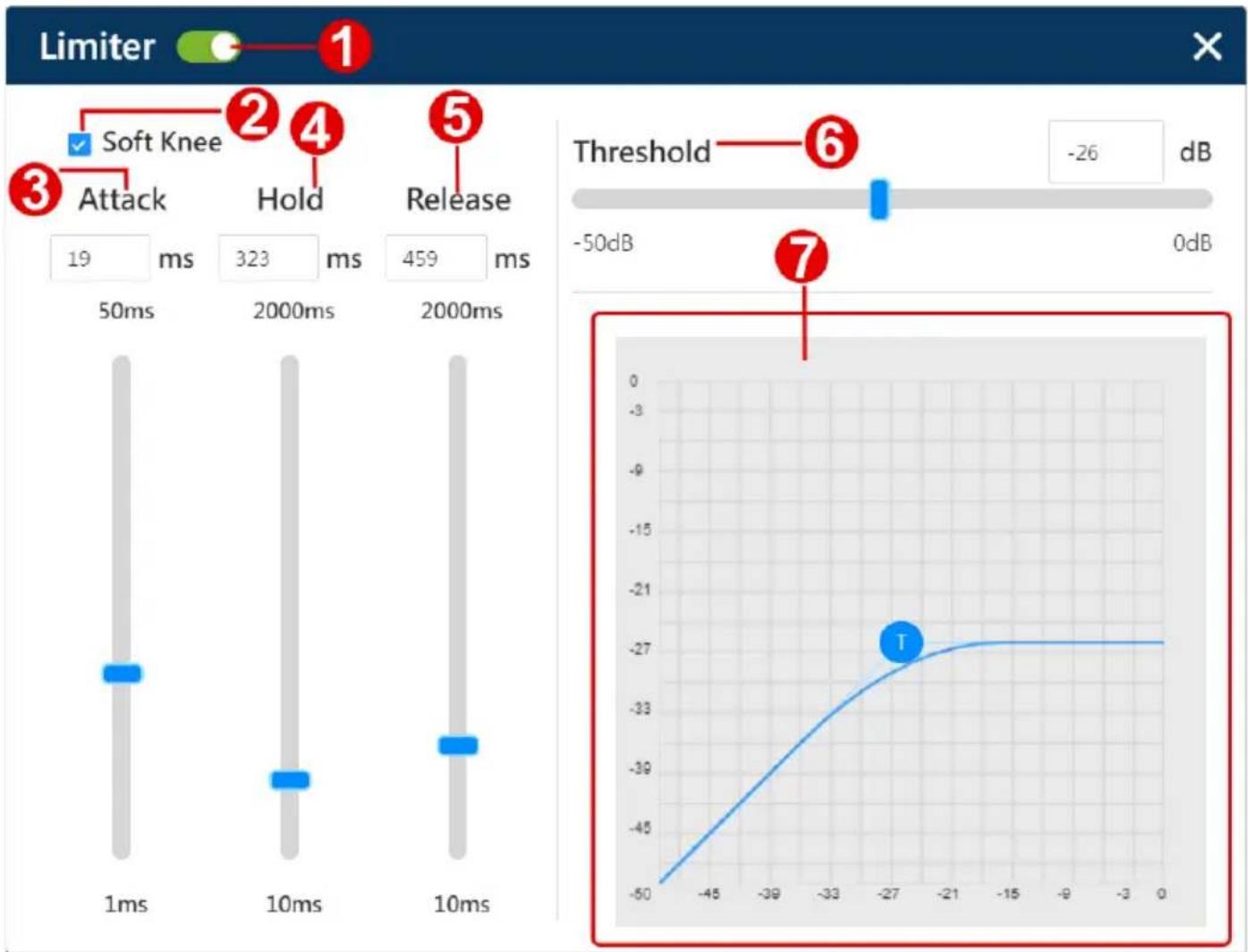
| No. | Item Description | |
| 1 | limiter switch | Turn on the switch to enable the limiter to stop the audio signal from increasing in loudness by setting a threshold. |
| No. Item | Description |
| 2 soft knee Set the knee setting that affects the limiting processing slope. The limiter gives a linear or non-linear response curve according to the knee settings that controls how the limiter effects on an audio signal.◆ Hard knee:A hard knee setting is enable when the checkbox of soft knee is unchecked. A hard knee curve in the graph is with a hard cutoff angle. The limiting process starts at the threshold, and the output audio sound is powerful and punchy.◆ Soft knee:Check the checkbox to enable a soft knee setting, and the limiting process occurs gradually. The output audio sound is smoother and subtle. The curve of a soft knee in the graph is more rounded bended. | |
| 3 attack setting Define the reaction speed that the limiter engage to limit peaks of an audio signal that exceeds the threshold. Specify a millisecond value for the attack setting by manually inputting the value in the field or dragging the slider. | |
| 4 hold setting Set an additional amount of time that the full gain reduction is maintained after the signal drops below the threshold. The release phase will not begin until the hold period ends.Specify a millisecond value by manually inputting the value in the field or dragging the slider. | |
| 5 release setting Determine the amount of time that the limiter stops applying limiting on the audio signal once the signal level goes below the threshold.Specify a millisecond value by manually inputting the value in the field or dragging the slider. | |
| 6 threshold setting Set a threshold that trigger the limiter to limit the amount of voltage by reducing the input gain. Specify a decibel value by manually inputting the value in the field or dragging the slider.Note:A hard knee setting starts the limiting process right after the signal reaches the threshold while a soft knee setting applies the limiting as the audio signal approaches the threshold. | |
| 7 limiter graph Display the graph that illustrates the curve about how the limiter settings are applied. The T in the curve graph marks out the threshold, and you can drag the T or to change the threshold value. |
Line Out Processing
Through the line out operation panel, user can process the input line-level audio signals and send out the line-level signals to the audio output devices that connected to the unit's line out channels. The line out operation panel contains the following functions:
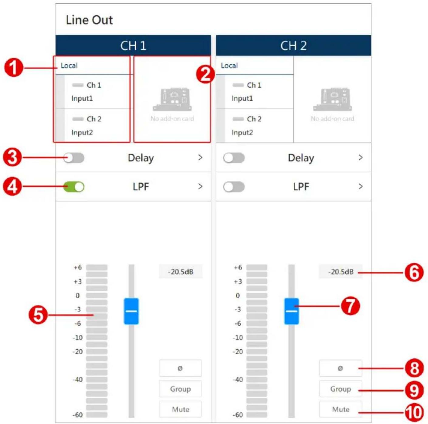
| No. | Item Description | |
| 1 | input signal control area | In the input signal area, you can:◆ Click to select the audio signal from input channel(s). You can select multiple input channels at a time.◆ Rename the input channels.See Input Signal Control, page 28. |
| 2 | expansion card | If you have the expansion card installed on the unit, this area becomes available and offers the same functions as the input signal control area does. |
| 3 | delay switch | Switch on or off to apply or withdraw the delay settings to the audio signal. Click on the function name to open the popup for further configurations. See Delay Configuration, page 37. |
| 4 | low-pass filter switch | Switch it on to enable the low-pass filter to cut the high frequency of the audio signal. See Low-pass Filter Configuration, page 38. |
| 5 | signal level meter Show the | audio signal levels in decibel (dB). |
| 6 | channel fader level Show | the volume level of the audio signal to be output. |
| 7 | channel fader Adjust the v | volume level of the audio signal to be output. Drag the fader to change the value in decibel. The volume value also displays in the channel fader level field next to the channel fader. |
| 8 | phase button | Click the button to invert the polarity of the phase. Disabling this function means that the phase polarity is normal. |
| 9 | fader group button | Enable the group function to add this channel to the linked channels to simultaneously control the volume levels. |
| 10 | mute button | Click on the mute button to enable or disable the mute function for this channel. |
Delay Configuration
The delay settings helps to synchronize multiple sets of speakers and improve audio clarity.
other
| Label | Value | |-------|-----------| | 1 | 1 | | 2 | 2 | | 3 | 3 | | 4 | 4 | | 5 | 5 | | 6 | 6 | | 7 | 7 || No. | Item Description | |
| 1 | delay settings switch | Turn on / off the switch to apply / withdraw the delay settings. |
| 2 | delay time slider Drag the | slider to set the delay time in millisecond. The time value is also shown in the delay time value field next to the slider. |
| 3 | delay time value Show the | delay time value in millisecond. You can directly input the value to this field to change the delay time value. |
| 4 | distance slider | Drag the slider to set the distance in feet or meters. The distance value is also shown in the distance value field next to the slider. |
| 5 | distance value Show the | distance in feet or meters. To change the value, do the followings:a) Input the value in the field.b) Click to select the unit of length between feet and meters. |
| 6 | temperature slider | Drag the slider to set the temperature in Celsius or Fahrenheit. The temperature value is also shown in the temperature value field next to the slider. |
| 7 | temperature value Show the | temperature in Celsius or Fahrenheit. To change the value, do the followings:a) Input the value in the field.b) Click to select the temperature scale between Celsius and Fahrenheit. |
Low-pass Filter Configuration
The low-pass filter (LPF) is to restricts the audio signal to be distributed below the configured frequency level. On this popup window, you can do the followings:
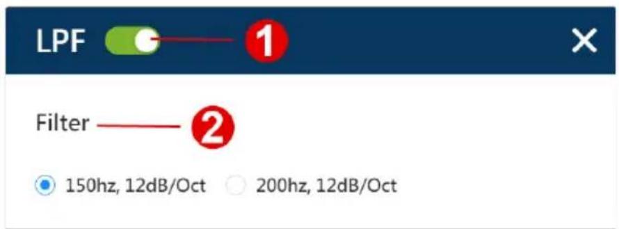
- Turn on or off the switch to apply or withdraw the LPF settings.
- Click the radio button to select the frequency level you'd like to set as the LPF.
Preset Management
All the settings you configured on both speaker out operation area and line out operation area can be saved as a preset. You can easily switch to other set of settings by applying an existing preset.
Save a New Preset
To save a new preset:
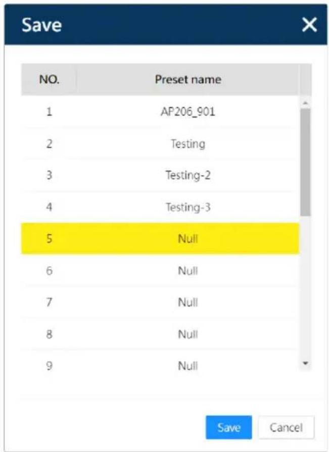
- Click on the save button to open the popup window.
- Click to select a Null item, and click on the save button.
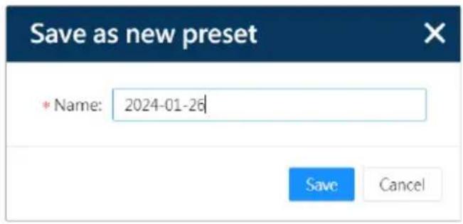
- Enter the name for this preset to be saved, and click on the save button to complete.
Apply an Existing Preset
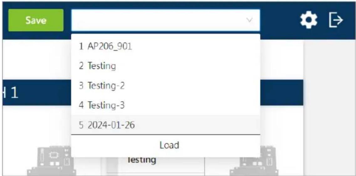
Click to open the preset menu, and select the one you need to apply.
Edit an Existing Preset
Fellow the steps below to edit an existing preset:
- Apply the preset you'd like to edit.
- Make changes of the preset. Once the configuration is done, click on the save button.
- The save popup window appears. Click on the preset name of this preset, and then click on the save button to save it.
- Confirm to overwrite the preset to save your changed settings.
System Settings
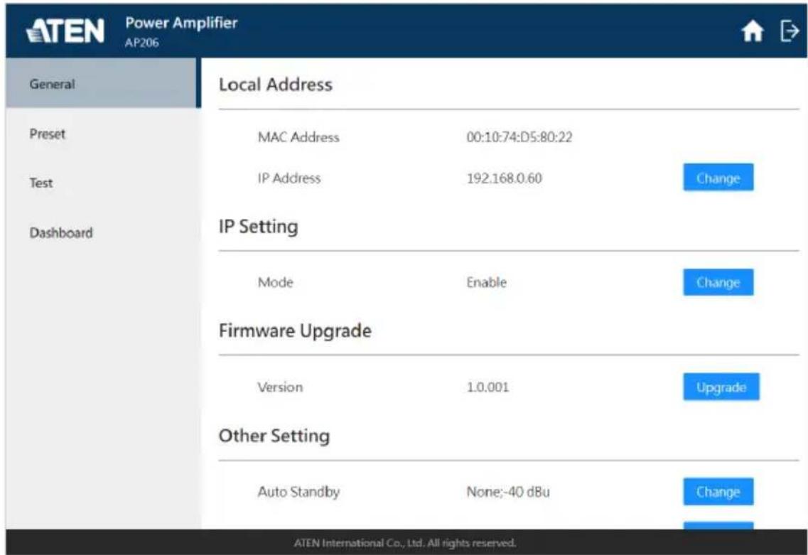
Click on the setting button on the DSP configuration screen to switch to here you can configure the followings:

| Tab Supported Functions Detailed Information | ||
| General | ◆ Configure the network settings.◆ Upgrade the unit's firmware.◆ Set the inactivity duration that triggers the unit enters a low-power mode.◆ Select the interface language.◆ Configure the passwords for Administrator and Operator.◆ Configure the account security settings. | For more information, see General Tab, page 43. |
| Preset | ◆ Edit the existing preset(s).◆ Delete the existing preset(s).◆ Import and export the preset(s). | For more information, see Preset Tab, page 50. |
| Test | ◆ Calibrate the connected audio equipments. | For more information, see Test Tab, page 53. |
| Dashboard | ◆ Check the status of the unit.◆ Export the status report of the unit. | For more information, see Dashboard Tab, page 54. |
Note: Only Administrator can access to the system settings page.
General Tab
The General tab allows the Administrator to control or customize various settings that are used throughout the unit's configuration system.
Local Address
| Local Address | ||
| MAC Address | 00:10:74:D5:80:22 | |
| IP Address | 192.168.0.60 | Change |
| Item Description | |
| MAC Address Shows the MAC address (media access control address) that is assigned to the unit connected to the network. | |
| IP Address | Shows the IP address of this unit. Click on the change button next to the IP address to open the popup window to select the mode using the radio button: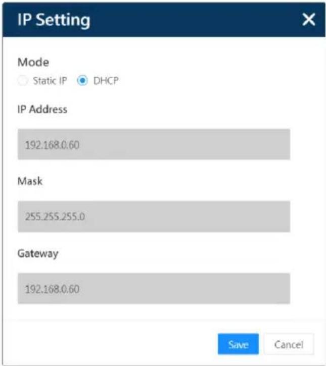 |
| Static IP:By selecting Static IP, the fields IP Address, Mask, and Gateway in this popup are available for you to define a fixed IP address for this unit.DHCP: Get the IP address that is assigned dynamically. | |
IP Settings
| IP Setting | ||
| Mode | Enable | Change |
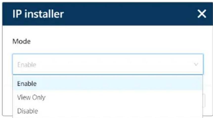
IP Settings is the function that works with the ATEN's program, IP Installer (see DHCP-assigned IP Address, page 21). Click on the change button to open the popup window and select the mode from the drop-down menu:
| Item Description | |
| Enable The unit's IP address can be found by IP Installer and configured through the Set IP function of IP Installer. | |
| View Only The unit's IP address can be found by IP Installer, but it cannot configured through IP Installer. | |
| Disable The unit's IP address cannot be found by IP Installer. |
Firmware Upgrade
| Firmware Upgrade | ||
| Version | 1.0.00 | Upgrade |
To upgrade the firmware of this unit, click the upgrade button to browse and select the firmware file from your PC.
Other Settings
Click on the change button next to the function you'd like to configure to open its popup window for further settings:
Other Setting
Auto Standby
15 min;-40 dBu
Change
Language
English
Change
Login Password
Change
Item Description
Auto Standby Define the followings by selecting the options from the drop-down menu:
Auto Standby

Standby after
None
Threshold
-40 dBu
Save
Cancel
Standby after
Set the duration that the unit automatically enters standby mode after an elapsed time of inactivity. The options are:
Threshold
Select the signal strength that trigger the wakeup of the unit.
| Item Description | |
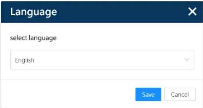
| Language Use the drop-down menu to select the web console interface language. | |
 | |
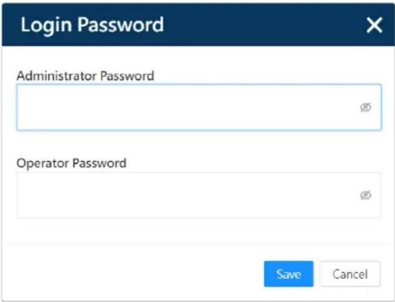
| Login Password Change the password for Administrator and Operator. | |
 | |
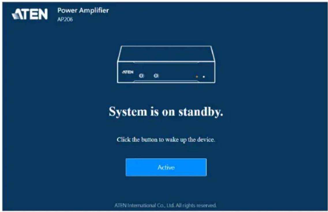
Note: By enabling the auto standby settings, you have to wake up the unit once the it enters the standby mode. Follow the on-screen instructions to complete.
Web Settings
Web Settings
Private Key & Certificate
Enable Telnet Server
Server port
Upload


only HTTPS

HTTP/HTTPS
| Item Description | |
Private Key & Certificate When logging in over a secure (SSL) connection, a signed certificate is used to verify that the user is logging in to the intended site. For enhanced security, the Private Certificate section allows you to use your own private encryption key and signed certificate, rather than the default ATEN certificate.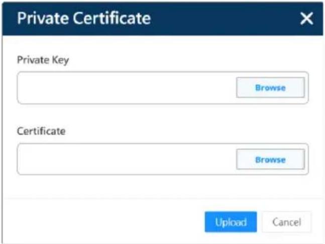 | |
| Enable Telnet Server | Check the checkbox to enable the Telnet login function that connects to the unit over a network to provide text based management and control. |
| Server Port Use the radio button to select only use HTTP for a browser login or both HTTP and HTTPS which is for a secure browser login. | |
Account Lockout Policy
Account Lockout Policy
Account Lockout

Enable

Disable
Maximum Invalid Login Attempts (1–99)
3
Account Lockout Duration (1-999 mins)
15
Account Lockout Policy helps to protect the accounts by limiting the number of failed login attempts.
| Item Description | Default | |
| Account Lockout To enable or disable the function that locks the login account after a certain number of failed sign-in attempts. | Enable | |
| Maximum Invalid Login Attempts (1–99) | Enter the maximum number of failed sign-in attempts. | 3 (attempts) |
| Account Lockout Duration (1–999 mins) | Define the number of minutes that a locked-out account remains locked out before it gets unlocked. | 15 (minutes) |
Preset Tab
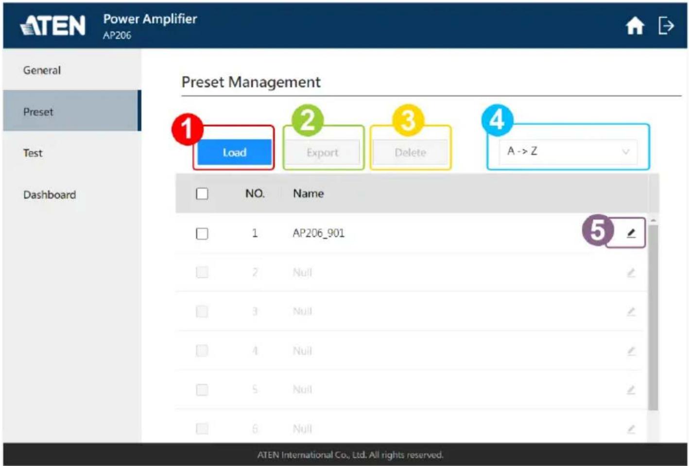
A preset is a set of settings that defines how the DSP manipulate the audio signal and configured by users in AP206 / AP212 web console. Preset tab lists all the saved presets, and on this tab page, Administrator can do the followings:
- Import the Preset(s) Settings:
To streamlining setup across units via configuration files, or to import your previously exported preset(s), do the followings:
a) Click the load button browse the .bin file saved in your PC, and select the one you'd like to load.
b) In Select Files list, choose the preset(s) to be imported by checking the checkbox(es), and then arrange for each preset the item order on Preset List.
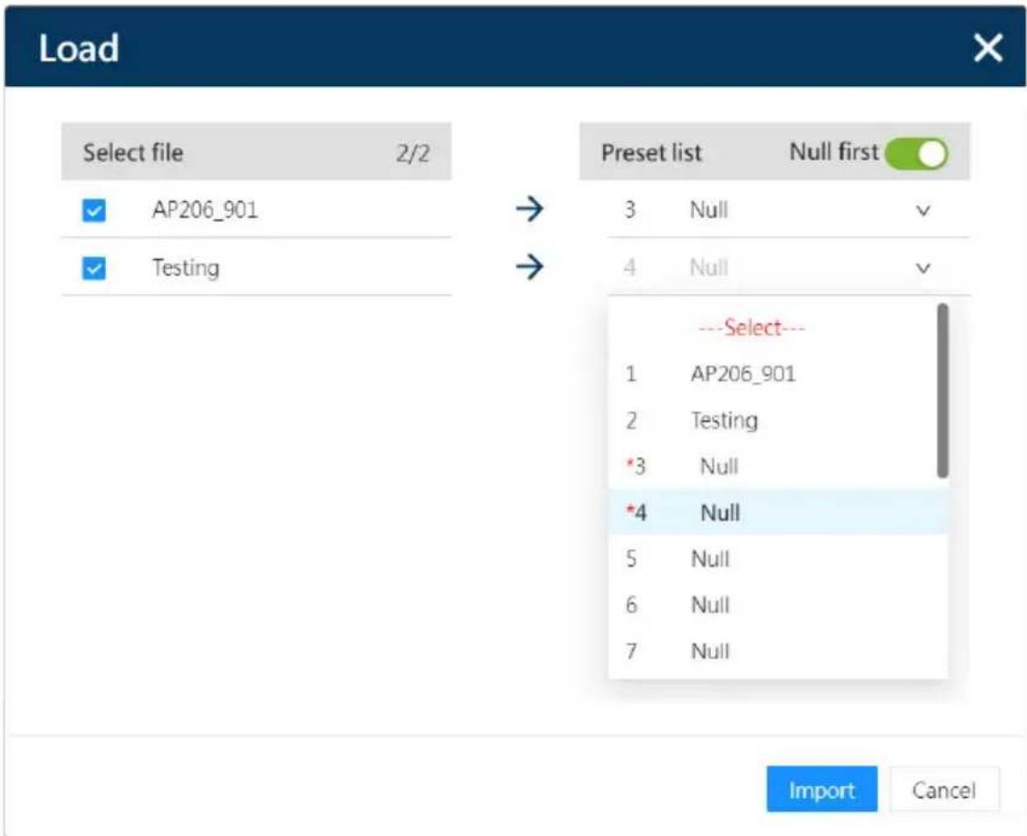
Note: By enabling Null First switch, the blank preset field will be preselected. To overwrite the existed preset field, manually select the field or disable Null First to preselect the filed from item no. 1.
c) Click on the import button to complete the action.
- Export the Preset(s) Settings:
To save the existed preset settings and export them as a .bin file, please select all the presets or check the checkbox(es) of the preset(s) to be exported, click the export button, and save them to your PC. Previously exported preset(s) can be imported again by Load function.
- Delete the Existed Preset(s):
Check the preset(s) to be removed, and then click on the delete button.
- Sort and Display the Presets Alphabetically:
To alphabetically sort and display the saved preset(s) in ascending order or in descending order, select A -> Z or Z -> A from the drop-down menu.
- Change the Preset Name:
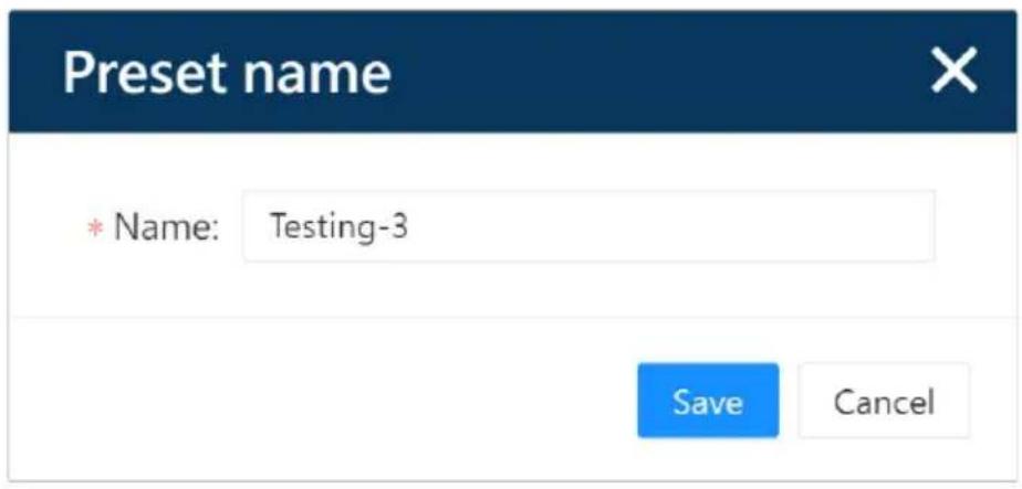
To change the name of the existed preset, click the edit button of the preset to be changed, enter the new name for this preset, and exit the editing filed. The preset name changes immediately.
Test Tab
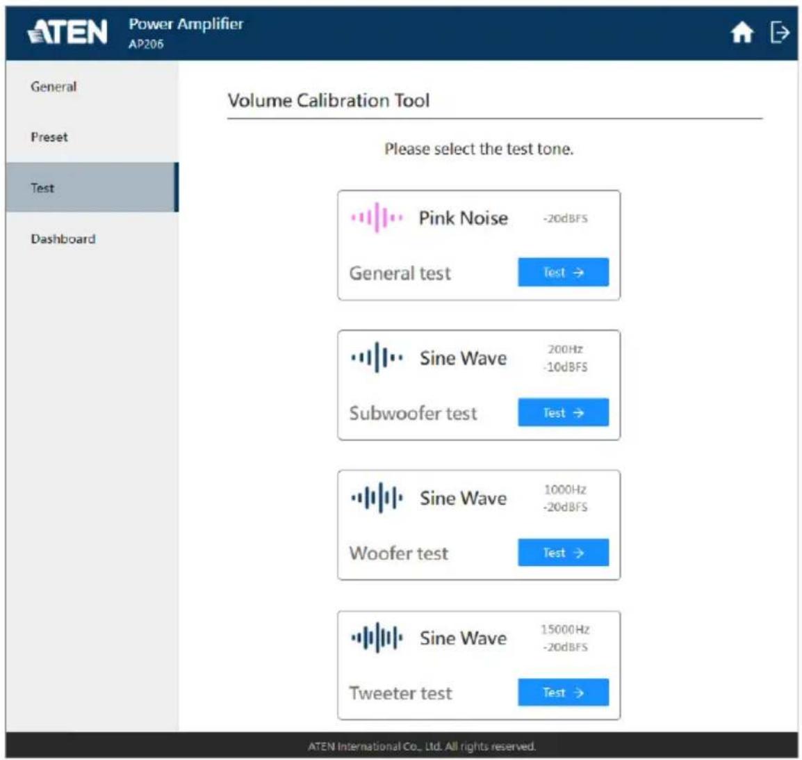
Test tab offers the methods that helps to calibrate the volume levels:
| Item | Testing Wave-form | Description |
| General Test | Pink Noise | Pink noise is ideal for the output volume level calibration because it consists of every frequency band at exactly the same level. |
| Subwoofer Test | Sine Wave | A sine wave represents a pure tone with a single frequency. Use the pure and consistent signal to measure and calibrate the performance of the audio equipments. |
| Woofer Test | ||
| Tweeter Test |
Follow the on-screen instructions to complete the test procedure and take the suggested action to adjust the gain settings if needed.
Dashboard Tab
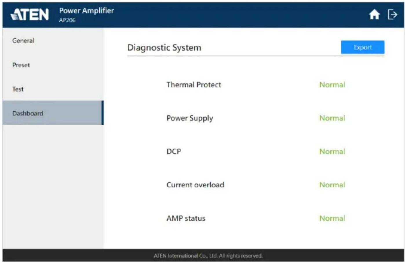
Currently the dashboard tab provides a diagnostic system that identifies the following operational status and the problems on the AP206 / AP212 unit.
- Thermal Protect
Power Supply
DCP - Current Overload
AMP Status
Through the export button, a report in .txt file format is generated. Use the generated report that contains the unit's event logs for troubleshooting if needed.
Safety Instructions
General
- This product is for indoor use only.
- Read all of these instructions. Save them for future reference.
◆ Follow all warnings and instructions marked on the device. - Do not place the device on any unstable surface (cart, stand, table, etc.). If the device falls, serious damage will result.
- Do not use the device near water.
- Do not place the device near, or over, radiators or heat registers.
- The device cabinet is provided with slots and openings to allow for adequate ventilation. To ensure reliable operation, and to protect against overheating, these openings must never be blocked or covered.
- The device should never be placed on a soft surface (bed, sofa, rug, etc.) as this will block its ventilation openings. Likewise, the device should not be placed in a built-in enclosure unless adequate ventilation has been provided.
- Never spill liquid of any kind on the device.
- Unplug the device from the wall outlet before cleaning. Do not use liquid or aerosol cleaners. Use a damp cloth for cleaning.
- The device should be operated from the type of power source indicated on the marking label. If you are not sure of the type of power available, consult your dealer or local power company.
- To prevent damage to your installation it is important that all devices are properly grounded.
Do not allow anything to rest on the power cord or cables. Route the power cord and cables so that they cannot be stepped on or tripped over. - Position system cables and power cables carefully; Be sure that nothing rests on any cables.
-
Never push objects of any kind into or through cabinet slots. They may touch dangerous voltage points or short out parts resulting in a risk of fire or electrical shock.
-
Do not attempt to service the device yourself. Refer all servicing to qualified service personnel.
If the following conditions occur, unplug the device from the wall outlet and bring it to qualified service personnel for repair.
◆ The power cord or plug has become damaged or frayed.
◆ Liquid has been spilled into the device.
- The device has been exposed to rain or water.
- The device has been dropped, or the cabinet has been damaged.
- The device exhibits a distinct change in performance, indicating a need for service.
- The device does not operate normally when the operating instructions are followed.
- Only adjust those controls that are covered in the operating instructions. Improper adjustment of other controls may result in damage that will require extensive work by a qualified technician to repair.
- To prevent electric shock, please do not remove the top cover as there are no user serviceable parts inside. Please refer to qualified service personnel for servicing.
- To completely disconnect this apparatus from the AC mains, disconnect the power supply cord plug from the AC receptacle.
- Exposed high voltage on the speaker out. Touching uninsulated terminals of wiring may result in an unpleasant sensation.
Rack Mounting
Before working on the rack, make sure that the stabilizers are secured to the rack, extended to the floor, and that the full weight of the rack rests on the floor. Install front and side stabilizers on a single rack or front stabilizers for joined multiple racks before working on the rack.
- Always load the rack from the bottom up, and load the heaviest item in the rack first.
- Make sure that the rack is level and stable before extending a device from the rack.
Use caution when pressing the device rail release latches and sliding a device into or out of a rack; the slide rails can pinch your fingers.
- After a device is inserted into the rack, carefully extend the rail into a locking position, and then slide the device into the rack.
Do not overload the AC supply branch circuit that provides power to the rack. The total rack load should not exceed 80 percent of the branch circuit rating.
- Make sure that all equipment used on the rack – including power strips and other electrical connectors – is properly grounded.
- Ensure that proper airflow is provided to devices in the rack.
- Ensure that the operating ambient temperature of the rack environment does not exceed the maximum ambient temperature specified for the equipment by the manufacturer.
- Do not step on or stand on any device when servicing other devices in a rack.
- For desktop mounting, install the unit in an open and unobstructed area.
Technical Support
International
For online technical support – including troubleshooting, documentation, and software updates: http://support.aten.com
- For telephone support, see Telephone Support, page iv:
North America
| Email Support support@aten-usa.com | ||
| Online Technical Support | Troubleshooting Documentation Software Updates | http://www.aten-usa.com/support |
| Telephone Support 1-888-999-ATEN ext 4988 | ||
When you contact us, please have the following information ready beforehand:
Product model number, serial number, and date of purchase
- Your computer configuration, including operating system, revision level, expansion cards, and software
◆ Any error messages displayed at the time the error occurred
◆ The sequence of operations that led up to the error
◆ Any other information you feel may be of help
Specifications
AP206
| Function AP206 | |
| System Specification | |
| Rated Power 60W per Channel, 120W at Bridge Mode | |
| Distortion THD+N: <0.1%, 1kHz, 3dB before clipping | |
| Frequency Response 50-20kHz, +/-3dB @4Ω, 1W | |
| Sensitivity Balanced: +4dBu | Unbalanced: -10dBV(0dBu=0.775Vrms, 0dBV=1Vrms) |
| Amplifier Type Class D | |
| Audio Inputs | |
| Interfaces 2 × 3-pin 3.5mm Euroblock (Bal/Unbal Line In) | |
| Impedance Balanced: 20kΩ / Unbalanced: 10kΩ | |
| Detect Threshold -50dBu | |
| Audio Outputs | |
| Interfaces Line Output: 1 × 5-pin 3.5mm EuroblockSpeaker Output: 1 × 2-pin 5.08mm Euroblock | |
| Impedance Lo-Z: 4Ω / Hi-Z: 70V (40Ω), 100V (80Ω)Line Output: 600Ω | |
| Audio Effects Built-In DSP | |
| Protection Output Shortcut | AMP Output over/under voltageHigh Frequency OverloadThermal Protect |
| Communication | |
| RS-232 Connector: 3-pin, 3.5mm, Terminal BlockBaud rate and protocol:Baud Rate: 19200, Data Bits: 8, Stop Bits:1, Parity: No, Flow Control: No | |
| Power | |
| Power Consumption 100-240V~, 50/60Hz, 2A with PFC | |
| Compliance | |
| Certification FCC, CE, UKCA | |
| Environmental | |
| Operating Temperature 0°C | -50°C |
| Humidity 0%-80% RH, Non- | Condensing |
| Storage Temperature -20°C | -60°C |
| Physical Properties | |
| Weight 2.4kg | |
| Housing Metal | |
| Dimensions (L x W x H) 200mm × 300mm × 44mm | |
AP212
| Function AP212 | |
| System Specification | |
| Rated Power 120W per Channel, 240W at Bridge Mode | |
| Distortion THD+N: <0.1%, 1kHz, 3dB before clipping | |
| Frequency Response 50–20kHz, +/-3dB @4Ω, 1W | |
| Sensitivity Balanced: +4dBu | Unbalanced: -10dBV(0dBu=0.775Vrms, 0dBV=1Vrms) |
| Amplifier Type Class D | |
| Audio Inputs | |
| Interfaces 2 × 3-pin 3.5mm Euroblock (Bal/Unbal Line In) | |
| Impedance Balanced: 20kΩ / Unbalanced: 10kΩ | |
| Detect Threshold -50dBu | |
| Audio Outputs | |
| Interfaces Line Output: 1 × 5-pin 3.5mm EuroblockSpeaker Output: 1 × 2-pin 5.08mm Euroblock | |
| Impedance Lo-Z: 4Ω / Hi-Z: 70V (40Ω), 100V (80Ω)Line Output: 600Ω | |
| Audio Effects Built-In DSP | |
| Protection Output Shortcut | AMP Output over/under voltageHigh Frequency OverloadThermal Protect |
| Communication | |
| RS-232 Connector: 3-pin, 3.5mm, Terminal BlockBaud rate and protocol:Baud Rate: 19200, Data Bits: 8, Stop Bits:1, Parity: No, Flow Control: No | |
| Power | |
| Power Consumption 100–240V~, 50/60Hz, 4A with PFC | |
| Compliance | |
| Certification FCC, CE, UKCA | |
| Environmental | |
| Operating Temperature 0°C | -50°C |
| Humidity 0%-80% RH, Non- | Condensing |
| Storage Temperature -20°C | -60°C |
| Physical Properties | |
| Weight 2.4kg | |
| Housing Metal | |
| Dimensions (L x W x H) 200mm × 300mm × 44mm | |
AP901
| Function AP901 | |
| Network Protocol | |
| 1000/10000 Mbps Dante Ultimo | |
| Connector RJ45 | |
| Audio Sampling 24-bit, 44.1/48kHz | |
| Compliance | |
| Certification FCC, CE, UKCA | Tested with AP2 Amplifier |
| Environmental | |
| Operating Temperature 0°C-50°C | |
| Humidity 0%-80% RH, Non-Condensing | |
| Storage Temperature -20°C-60°C | |
| Physical Properties | |
| Weight 0.12 kg (0.27 lb) | |
| Housing Metal Panel | |
| Dimensions (L x W x H) 11.50 × 2.20 × 1.00 cm(4.53 × 0.87 × 4.33 in.) | |
AP902
| Function | AP902 |
| Microphone Inputs | |
| Gain Range -6-+36dB | |
| Impedance 3kΩ | |
| Line Inputs | |
| Gain Range -6-+36dB | |
| Maximum Input Level +24dBu, Nominal Input Level: +4dBu | |
| Impedance Balanced: 20kΩ | Unbalanced: 10kΩ |
| System Specification | |
| Distortion THD+N: Line In <0 | .01%, +4dBu @1kHz, 0dB GainMic In <0.25%, -20dBu, @1kHz, 0dB Gain |
| Frequency Response 50-20kHz, +/-0.5dB, Line In to ATEN AP2 Line Out | |
| Compliance | |
| Certification FCC, CE, UKCA | Tested with AP2 Amplifier |
| Environmental | |
| Operating Temperature 0°C-50°C | |
| Humidity 0%-80% RH, Non-Condensing | |
| Storage Temperature -20°C-60°C | |
| Physical Properties | |
| Weight 0.12 kg (0.27 lb) | |
| Housing Metal Panel | |
| Dimensions (L x W x H) 11.50 × 2.20 × 1.00 cm(4.53 × 0.87 × 4.33 in.) | |
ATEN Standard Warranty Policy
Limited Hardware Warranty
ATEN warrants its hardware in the country of purchase against flaws in materials and workmanship for a Warranty Period of two [2] years (warranty period may vary in certain regions/countries) commencing on the date of original purchase. This warranty period includes the LCD panel of ATEN LCD KVM switches. For UPS products, the device warranty is two [2] years but battery is one [1] year. Select products are warranted for an additional year (see A+ Warranty for further details). Cables and accessories are not covered by the Standard Warranty.
What is covered by the Limited Hardware Warranty
ATEN will provide a repair service, without charge, during the Warranty Period. If a product is detective, ATEN will, at its discretion, have the option to (1) repair said product with new or repaired components, or (2) replace the entire product with an identical product or with a similar product which fulfills the same function as the defective product. Replaced products assume the warranty of the original product for the remaining period or a period of 90 days, whichever is longer. When the products or components are replaced, the replacing articles shall become customer property and the replaced articles shall become the property of ATEN.
To learn more about our warranty policies, please visit our website: http://www.aten.com/global/en/legal/policies/warranty-policy/
© Copyright 2024 ATEN® International Co., Ltd.
Released: 2024-02-01
ATEN and the ATEN logo are registered trademarks of ATEN International Co., Ltd. All rights reserved. All other brand names and trademarks are the registered property of their respective owners.
- Compliance Statements
- FEDERAL COMMUNICATIONS COMMISSION INTERFERENCE STATEMENT
- KCC Statement
- Industry Canada Statement
- CAN ICES-003 (B) / NMB-003 (B)
- Trademark Statement
- ENERGY STAR Certification
- RoHS
- User Information
- Online Registration
- Telephone Support
- User Notice
- Product Information
- Package Contents
- Table of Contents
- Introduction
- Hardware Setup
- Operation
- Appendix
- About this Manual
- Note:
- Conventions
- Chapter 1
- Introduction
- Overview
- Features
- Planning the Installation
- Requirements
- Components
- LED Status
- Chapter 2
- Hardware Setup
- Connecting the AP206 / AP212 Unit
- Mounting the AP206 / AP212 Unit
- Rack Mount
- Surface Mount
- Expansion Card
- Hardware Overview
- AP901
- AP902
- Configuring Audio Gain on AP902
- Installing / Removing the Expansion Card
- Installing
- Removing
- Browser Web Control
- DHCP-assigned IP Address
- Login
- DSP Configuration
- Speaker Out Processing
- Input Signal Control
- Speaker Selector
- Delay Configuration
- Equalizer Configuration
- Limiter Configuration
- Line Out Processing
- Low-pass Filter Configuration
- Preset Management
- Save a New Preset
- Apply an Existing Preset
- Edit an Existing Preset
- System Settings
- General Tab
- Local Address
- IP Settings
- Firmware Upgrade
- Other Settings
- Other Setting
- Item Description
- Auto Standby
- Web Settings
- Account Lockout Policy
- Preset Tab
- Test Tab
- Dashboard Tab
- Safety Instructions
- General
- Rack Mounting
- Technical Support
- International
- North America
- Specifications
- ATEN Standard Warranty Policy
- Limited Hardware Warranty
- What is covered by the Limited Hardware Warranty
Brand : ATEN
Model : AP902
Category : Receiver