
KE6940AR - Receiver ATEN - Free user manual and instructions
Find the device manual for free KE6940AR ATEN in PDF.


| Product Type | KVM over IP Receiver |
| Brand | ATEN |
| Model | KE6940AR |
| Video Interface | DVI-I (dual display) |
| Max Video Resolution | 1920 x 1200 @ 60 Hz (24-bit color) |
| Supported Resolutions | 640x480 to 1920x1200 @ 60 Hz; also 2048x2048 @ 60 Hz (2Kx2K) |
| Number of Displays | 2 (dual display) |
| Audio Support | 2-channel analog stereo (line in/out, microphone) |
| USB Ports | 2 x USB Type A (console keyboard/mouse), 1 x USB Type A (peripheral/virtual media) |
| Serial Port | 1 x RS-232 (DB-9 male) for serial terminal configuration |
| Network Interface | 1 x RJ-45 Gigabit Ethernet, 1 x SFP slot (1GbE fiber) |
| Power Source | DC 5V, 6.58W; dual power jacks for redundancy |
| Power Supply | External power adapter (included) |
| Dimensions (L x W x H) | 20.00 x 16.30 x 3.00 cm (7.87 x 6.42 x 1.18 in) |
| Weight | 0.60 kg (1.32 lb) |
| Operating Temperature | 0°C to 50°C (32°F to 122°F) |
| Humidity | 0% to 80% RH (non-condensing) |
| Mounting | Rack-mountable (optional kit), wall-mountable (via bracket) |
| Package Contents | Receiver, power adapter & cord, user instructions |
| Management | On-Screen Display (OSD) on receiver; KE Matrix Manager software (CCKM) for centralized control |
| Security | Username/password authentication, remote login security, authentication lock (on compatible models) |
| Special Features | Connection redundancy, intelligent dual video output management, boundless switching, video wall support, firmware upgradeable |
| Compliance | FCC Class A, RoHS |
Frequently Asked Questions - KE6940AR ATEN
User questions about KE6940AR ATEN
0 question about this device. Answer the ones you know or ask your own.
Ask a new question about this device
Download the instructions for your Receiver in PDF format for free! Find your manual KE6940AR - ATEN and take your electronic device back in hand. On this page are published all the documents necessary for the use of your device. KE6940AR by ATEN.
USER MANUAL KE6940AR ATEN
KVM over IP Matrix Series:
KVM over IP Extender &
CCKM KE Matrix Manager Software
User Manual
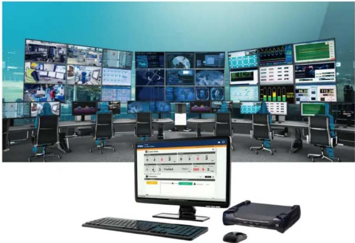
natural_image
Control room with multiple large display screens and a central monitor displaying a waveform graph (no readable text or symbols)EMC Information
FEDERAL COMMUNICATIONS COMMISSION INTERFERENCE STATEMENT: This equipment has been tested and found to comply with the limits for a Class A digital device, pursuant to Part 15 of the FCC Rules. These limits are designed to provide reasonable protection against harmful interference when the equipment is operated in a commercial environment. This equipment generates, uses, and can radiate radio frequency energy and, if not installed and used in accordance with the instruction manual, may cause harmful interference to radio communications. Operation of this equipment in a residential area is likely to cause harmful interference in which case the user will be required to correct the interference at his own expense.
The device complies with Part 15 of the FCC Rules. Operation is subject to the following two conditions: (1) this device may not cause harmful interference, and (2) this device must accept any interference received, including interference that may cause undesired operation.
FCC Caution: Any changes or modifications not expressly approved by the party responsible for compliance could void the user's authority to operate this equipment.
Warning: Operation of this equipment in a residential environment could cause radio interference.
KCC Statement
This product is RoHS compliant.

User Information
Online Registration
Be sure to register your product at our online support center:
International http://eservice.aten.com
Telephone Support
For telephone support, call this number:
| International 886-2-86 | 92-6959 |
| China 86-400-810-0-8 | 10 |
| Japan 81-3-5615-5811 | |
| Korea 82-2-467-6789 | |
| North America 1-888-999-ATEN ext 49881-949-428-1111 | |
User Notice
All information, documentation, and specifications contained in this manual are subject to change without prior notification by the manufacturer. The manufacturer makes no representations or warranties, either expressed or implied, with respect to the contents hereof and specifically disclaims any warranties as to merchantability or fitness for any particular purpose. Any of the manufacturer's software described in this manual is sold or licensed as is. Should the programs prove defective following their purchase, the buyer (and not the manufacturer, its distributor, or its dealer), assumes the entire cost of all necessary servicing, repair and any incidental or consequential damages resulting from any defect in the software.
The manufacturer of this system is not responsible for any radio and/or TV interference caused by unauthorized modifications to this device. It is the responsibility of the user to correct such interference.
The manufacturer is not responsible for any damage incurred in the operation of this system if the correct operational voltage setting was not selected prior to operation. PLEASE VERIFY THAT THE VOLTAGE SETTING IS CORRECT BEFORE USE.
About This Manual
This User Manual is provided to help you get the most from your KVM over IP Matrix System. It covers all aspects of installation, configuration and operation. An overview of the information found in the manual is provided below.
The KVM over IP Extender models covered in this user manuals are:
| Models | Product Names |
| KE6900 DV | Single Display KVM over IP Extender (Transmitter & Receiver) |
| KE6900A D | VI-I Single Display KVM over IP Extender (Transmitter & Receiver) |
| KE6900ST | DVI KVM over IP Extender Lite |
| KE6910 DV | -D Dual Link KVM over IP Extender (Transmitter & Receiver) |
| KE6912 DV | -D Dual Link KVM over IP Extender (Transmitter & Receiver) with PoE |
| KE6920 DV | -D Dual Link KVM over IP Extender (Transmitter & Receiver) with Dual SFP |
| KE6922 DV | -D Dual Link KVM over IP Extender (Transmitter & Receiver) with Dual SFP & PoE |
| KE6940 DV | Dual Display KVM over IP Extender (Transmitter & Receiver) |
| KE6940A D | VI-I Dual Display KVM over IP Extender (Transmitter & Receiver) |
| KE8900S S | im HDMI KVM over IP Extender (Transmitter & Receiver) |
| KE8950 4K | HDMI Single Display KVM over IP Extender (Transmitter & Receiver) |
| KE8952 4K | HDMI Single Display KVM over IP Extender (Transmitter & Receiver) with PoE |
| KE9900ST | Slim DisplayPort KVM over IP Extender (Transmitter) |
| KE9950 | 4K DisplayPort KVM over IP Extender (Transmitter & Receiver) |
| KE9952 | 4K DisplayPort KVM over IP Extender (Transmitter & Receiver) with PoE |
Copyright © 2020 ATEN® International Co., Ltd.
Altusen and the ATEN logo are registered trademarks of ATEN International Co., Ltd. All rights reserved. All other brand names and trademarks are the registered property of their respective owners.
Chapter 1, Introduction, introduces you to the KVM over IP Matrix System. Its purpose, features and benefits are presented, and its front and back panel components are described.
Chapter 2, Hardware Setup, provides step-by-step instructions for setting up your installation, and explains some basic operation procedures.
Chapter 3, OSD Operation, explains the fundamental concepts involved in operating the KE6900 / KE6900A / KE6900ST / KE6910 / KE6912 / KE6920 / KE6922 / KE6940 / KE6940A / KE8900S / KE8950 / KE8952 / KE9900ST / KE9950 / KE9952, and provides a complete description of the On Screen Displays (OSDs) and how to work with them.
Chapter 4, Software Installation, explains the administrative procedures that are required to download and install the KE Matrix Manager software on Windows and Linux computers.
Chapter 5, Browser / Telnet Operation, explains how to log in to the KE Matrix Manager with a web browser, and describes the features, functions, and how to work with the browser's main interface.
Chapter 6, System Status, explains how to use the KE Matrix Manager's System Status panel to manage Transmitters, Receivers, Users, Profiles and Logs.
Chapter 7, System Settings, explains the KE Matrix Manager's system settings, which include the General, ANMS, LDAP/AD, RADIUS, TACACS+ authentication, F/W Upgrade, Redundancy, Backup/Restore, Certificates, and Sessions tabs.
Chapter 8, Connections, describes how to use the KE Matrix Manager ‘s Connections panel to view and disconnect Transmitter and Receiver connections.
Chapter 9, Scheduled Profile, describes how to use the KE Matrix Manager's Scheduled Profile panel to view active profile schedules.
Chapter 10, Sessions, describes how to use the KE Matrix Manager's Sessions panel to view and disconnect user sessions.
Chapter 11, Firmware Upgrade Utility, explains how to download and use the Firmware Upgrade Utility to install new firmware on the devices.
Chapter 12, CLI Commands, provides a complete list of the serial protocol and TCP/IP commands used when utilizing the RS-232 Serial Port or a network connection to configure the KE devices.
An Appendix, at the end of the manual provides technical and troubleshooting information.
Contents
EMC Information....ii
RoHS.ii
User Information ....iii
Online Registration .....iii
Telephone Support .....iii
User Notice ....iii
About This Manual iv
Contents ...... vii
Package Contents ...... xv
KE6900 / KE6940 ...... xv
KE6900A / KE6940A....xv
KE6900ST....xvi
KE6910 / KE6912 ..... xvi
KE6920 / KE6922 ..... xvi
KE8900S.... xvii
KE8950 / KE8952 ...... xviii
KE9900ST......xviii
KE9950 / KE9952 ...... xviii
Conventions xx
Product Information.... xx
Chapter 1. Introduction
Overview 1
Features 4
Supported Video Resolutions ....6
Requirements 7
Console....7
Computers....7
Cables....7
Minimum Hardware/Software Requirements. 7
Components 9
KE6900T (Transmitter) Front View 9
KE6900T (Transmitter) Rear View 10
KE6900R (Receiver) Front View 12
KE6900R (Receiver) Rear View 14
KE6900AT (Transmitter) Front View 16
KE6900AT (Transmitter) Rear View 17
KE6900AR (Receiver) Front View 19
KE6900AR (Receiver) Rear View 21
KE6910T / KE6912T (Transmitter) Front View 23
KE6910T / KE6912T (Transmitter) Rear View .....24
KE6910R / KE6912R (Receiver) Front View 26
KE6910R / KE6912R (Receiver) Rear View .....27
KE6920T / KE6922T (Transmitter) Front View ..... 29
KE6920T / KE6922T (Transmitter) Rear View 30
KE6920R / KE6922R (Receiver) Front View 32
KE6920R / KE6922R (Receiver) Rear View 33
KE6940T (Transmitter) Front View 35
KE6940T (Transmitter) Rear View 36
KE6940R (Receiver) Front View 38
KE6940R (Receiver) Rear View 40
KE6940AT (Transmitter) Front View 42
KE6940AT (Transmitter) Rear View 43
KE6940AR (Receiver) Front View 45
KE6940AR (Receiver) Rear View 47
KE6900ST (Transmitter) Front, Rear and Top View ..... 49
KE8950T / KE8952T (Transmitter) Front View 51
KE8950T / KE8952T (Transmitter) Rear View ..... 52
KE8950R / KE8952R (Receiver) Front View 54
KE8950R / KE8952R (Receiver) Rear View 56
KE8900ST (Transmitter) Front, Rear and Side View ..... 58
KE8900SR (Receiver) Front, Rear and Side View .....60
KE9900ST (Transmitter) Front, Rear and Side View ..... 62
KE9950T / KE9952T (Transmitter) Front View 64
KE9950T / KE9952T (Transmitter) Rear View ..... 65
KE9950R / KE9952R (Receiver) Front View 67
KE9950R / KE9952R (Receiver) Rear View 68
PoE Power Redundancy....69
Chapter 2.Hardware Setup
Mounting....71
Attaching the Bracket 72
Non-Slim Transmitters. 72
Slim Transmitters - KE6900ST 73
Slim Transmitters - KE8900ST / KE9900ST 73
Rack Mount 75
Non-Slim Transmitters. 75
Slim Transmitters - KE6900ST 76
Slim Transmitters - KE8900ST / KE9900ST 76
Wall Mounting 77
Non-Slim Transmitters. 77
Slim Transmitters - KE6900ST 78
Slim Transmitters - KE8900ST / KE9900ST . . . . . . . . . . . . . . . . . . . . . . . . . . 78
KE6900 / KE6940 Point-to-Point Installation 79
KE6900 / KE6940 Point-to-Point Installation 1 of 2. . . . . . . . . . . . . . . . . . . . . . . . . . . . . . . . . . . . . . . . . 80
KE6900 / KE6940 Point-to-Point Installation 2 of 2. . . . . . . . . . . . . . . . . . . . . . . . . . . . . . . . . . . . . . . . . 81
KE6900A / KE6940A Point-to-Point Installation 82
KE6900A / KE6940A Point-to-Point Installation 1 of 2 . . . . . . . . . . . . . . . . . . 83
KE6900A / KE6940A Point-to-Point Installation 2 of 2 . . . . . . . . . . . . . . 84
KE6910 / KE6912 Point-to-Point Installation 85
KE6910 / KE6912 Point-to-Point Installation 1 of 2. 86
KE6910 / KE6912 Point-to-Point Installation 2 of 2 ..... 87
KE6920 / KE6922 Point-to-Point Installation 88
KE6920 / KE6922 Point-to-Point Installation 1 of 2. 89
KE6920 / KE6922 Point-to-Point Installation 2 of 2 ..... 90
KE8950 / KE8952 Point-to-Point Installation 91
KE8950 / KE8952 Point-to-Point Installation 1 of 2. . . . . . . . . . . . . . . . . . . . . . . . . . . . . . . . . . . . . . . . . . . 92
KE8950 / KE8952 Point-to-Point Installation 2 of 2. . . . . . . . . . . . . . . . . . . . . . . . . . . . . . . . . . . . . . . . . . . . . . 93
KE6900ST Point-to-Point Installation .....94
Setting up a LAN Installation .....94
KE8900S Point-to-Point Installation 96
Setting up a LAN Installation .....96
KE9900ST Point-to-Point Installation . . . . . . . . . . . . . . . . . . . . . . . . . . . . . . . . . . . . . . . . . . . . . . . . . . . . . . . . . 98
Setting up a LAN Installation .....98
KE9950 / KE9952 Point-to-Point Installation 100
KE9950 / KE9952 Point-to-Point Installation 1 of 2. . . . . . . . . . . . . . . . . . . . . . . . . . . . . . . . . . . . . . . . . . . . . . . . . . . . . . . . . . . . . .
KE9950 / KE9952 Point-to-Point Installation 2 of 2. . . . . . . . . . . . . . . . . . . . . . . . . . . . . . . . . . . . . . . . . . . . . . . . . . . . . . . . . . . . . . . . . . .
KE6900 / KE6940 LAN Installation 103
KE6900 / KE6940 Network Installation Diagram 1 of 2 ..... 105
KE6900 / KE6940 Network Installation Diagram 2 of 2. . . . . . . . . . . . 106
KE6900A / KE6940A LAN Installation 107
KE6900A / KE6940A Network Installation Diagram 1 of 2 .....109
KE6900A / KE6940A Network Installation Diagram 2 of 2 .....110
KE6910 / KE6912 LAN Installation .....111
KE6910 / KE6912 Network Installation Diagram 1 of 2 ..... 112
KE6910 / KE6912 Network Installation Diagram 2 of 2. . . . . . . . . . . 113
KE6920 / KE6922 LAN Installation 114
KE6920 / KE6922 Network Installation Diagram 1 of 2 ..... 116
KE6920 / KE6922 Network Installation Diagram 2 of 2. . . . . . . . . . . 117
KE8950 / KE8952 LAN Installation 118
KE8950 / KE8952 Network Installation Diagram 1 of 2 ..... 120
KE8950 / KE8952 Network Installation Diagram 2 of 2. . . . . . . . . . . 121
KE9950 / KE9952 LAN Installation 122
KE9950 / KE9952 Network Installation Diagram 1 of 2 ..... 123
KE9950 / KE9952 Network Installation Diagram 2 of 2. . . . . . . . . . . 124
Network Configuration 125
Exit OSD 126
Default IP Addresses 126
KE I/O Ports 127
LED Display 128
Authentication Lock (KE6910 / KE6912 only) .....128
Chapter 3. OSD Operation
Overview 129
Invoking the OSD 129
Touch Screen Calibration .....129
OSD Hotkeys 130
Microphone Hotkey 130
OSD Interface....131
Receiver Configuration....132
Network....132
Properties 133
Regular Version....133
Slim Version 136
System 139
Transmitter Configuration....140
Network....140
Properties 141
System 144
User Preferences 145
Connecting 146
Logging in for the First Time 147
Connections Page....148
List Mode 148
Array Mode 151
Profile Page 153
Push Content 154
Pull Content 156
Chapter 4. Software Installation
Overview....159
Download - Trial Version 159
KE Matrix Manager Software Install 161
Upgrading Trial Version 164
Linux Installation 165
Chapter 5.Browser / Telnet Operation
Overview....169
Logging In....169
The KE Matrix Manager Main Page 171
Web Components....171
Installation Wizard 173
Instant Link 176
RS-232 / Telnet 178
Telnet 178
RS-232 179
Configuration Menu....180
Main Menu....180
-
Network 181
-
Properties ...... 181
-
System 182
Chapter 6. System Status
Overview 183
System Status 184
Transmitter 186
Transmitter Configuration .....188
Copy & Paste 193
Virtual Transmitter 194
Intelligent Dual Video Output Management .....195
Transmitter Group 196
Transmitter Permissions 197
Receiver 199
Receiver Configuration 201
Copy & Paste 205
Receiver Group 206
Video Wall....207
Receiver Permissions ....210
Account 211
Users 212
Adding Users....212
Modifying Users 214
Deleting Users 214
Groups 215
Adding Groups 215
Modifying Groups 216
Deleting Groups 216
Permissions 217
Assigning Device Permissions .....217
Profile 219
Adding a Profile .....220
Adding a Schedule .....223
Log 224
Chapter 7. System Settings
Overview 225
General....225
Connection Redundancy (KE6910 / 6912 only) .....228
ANMS 231
Event Destination .....231
Authentication & Authorization 233
FW Upgrade ....236
Firmware Upgrade Recovery 237
Redundancy 238
Private Certificate 242
Certificate Signing Request 243
Sessions 245
Chapter 8.Connections
Overview....247
Connections 248
Chapter 9.Scheduled Profile
Overview....251
Chapter 10.Sessions
Overview....253
Chapter 11. Firmware Upgrade Utility
Preparation....255
Starting the Upgrade 256
Upgrade Succeeded 258
Firmware Upgrade Recovery 259
Chapter 12.CLI Commands
Serial Control Protocol Commands 261
Configuring the Serial Port 261
Device/Profile Commands 262
Telnet 262
Verification 262
Switch Port Command 263
Mute Command 267
Profile Command 269
EDID Command 271
Reset Command 273
RS-232 Command 274
OSD Command 277
List Command 278
Read Command 280
Set Command 284
Appendix
Safety Instructions 293
General 293
Rack Mounting 295
Technical Support 296
International 296
North America 296
Specifications 297
KE6900T / KE6940T 297
KE6900R / KE6940R 299
KE6900AT / KE6940AT 300
KE6900AR / KE6940AR 302
KE6900ST 303
KE6910 304
KE6912 306
KE6920 308
KE6922 310
KE8900S 312
KE8950T / KE8952T 313
KE8950R / KE8952R 314
KE9900ST 315
KE9950 316
KE9952 318
Optional Rack Mounting 320
Dual Rack Mounting 320
Transmitter Dual Rack Mounting 320
Receiver Dual Rack Mounting 322
Single Rack Mounting 324
IP Installer 326
Trusted Certificates 327
Overview 327
Self-Signed Private Certificates 328
Examples 328
Importing the Files 328
Reset All Information 329
Default Password Pins ....330
RS-232 Pin Assignments 336
Transmitter Front RS-232 Port 336
Multicast IP Address 337
KE Multicast Rule 337
Multicast IP Formula 337
If X is between 0 \~ 127 ..... 337
If X is between 128 \~ 192 .....338
If X is 192 or higher 338
Keys to Network Performance 339
Build a Network Diagram 339
Other Factors....339
Choose a High Performance Switch 341
Layer 2 or Layer 3 Switches .... 341
Considerations 341
Number of ports 341
Stackable verse Standalone 341
What Stackable Switches Can do:....342
Switch Specifications 342
Configuring Switches and KE Devices . . . . . . . . . . . . . . . . . . . . . . . . . . . . . . . . . . . . . . . . . . 343
KE transmitter Settings: 343
Recommended Network Switches 343
Setup CCKM Server IP address on Windows 345
Limited Warranty....346
Package Contents
KE6900 / KE6940
Package content of KE6900T / KE6940T DVI Single/Dual Display KVM over IP Extender (Transmitter):
1 Transmitter
1 USB DVI-D KVM Cable
1 DVI-D Cable 1.8 m (for KE6940T)
1 Foot Pad Set
1 Power Adapters
1 Mounting Kit
1 User Instructions*
Package content of KE6900R / KE6940R DVI Single/Dual Display KVM over IP Extender (Receiver):
1 Receiver
1 Power Adapters
1 User Instructions*
KE6900A / KE6940A
Package content of KE6900AT / KE6940AT DVI-I Single / Dual Display KVM over IP Transmitter:
1 Transmitter
1 USB DVI-D KVM Cable
1 DVI-D Cable 1.8 m (for KE6940AT)
1 Power Adapter & Power Cord
1 Foot Pad Set
1 Mounting Kit
1 User Instructions*
Package content of KE6900AR / KE6940AR DVI-I Single / Dual Display KVM over IP Receiver:
1 Receiver
1 Power Adapter & Power Cord
1 User Instructions*
KE6900ST
Package content of KE6900ST DVI KVM over IP Extender Lite:
1 Transmitter
1 USB DVI-D KVM Cable
1 Foot Pad Set
1 Power Adapter
1 Mounting Kit
1 User Instructions*
KE6910 / KE6912
Package content of KE6910T / KE6912T DVI-D Dual Link KVM over IP Extender (Transmitter):
1 Transmitter
1 USB DVI-D KVM Cable
1 Power Adapter & Power Cord (for KE6910T)
1 Foot Pad Set
1 Mounting Kit
1 User Instructions*
Package content of KE6910R / KE6912R DVI-D Dual Link KVM over IP Extender (Receiver):
1 Receiver
1 Power Adapter & Power Cord (for KE6910R)
1 User Instructions*
KE6920 / KE6922
Package content of KE6920T DVI-D Dual Link KVM over IP Extender with Dual SFP (Transmitter) / KE6922T DVI-D Dual Link KVM over IP Extender with Dual SFP & PoE (Transmitter):
1 Transmitter
1 USB DVI-D KVM Cable
1 Power Adapter & Power Cord (for KE6910T)
1 Foot Pad Set
1 Mounting Kit
1 User Instructions*
Package content of KE6920R DVI-D Dual Link KVM over IP Extender with Dual SFP (Receiver) / KE6922R DVI-D Dual Link KVM over IP Extender with Dual SFP & PoE (Receiver):
1 Receiver
1 Power Adapter & Power Cord (for KE6910R)
1 User Instructions*
KE8900S
Package content of KE8900ST Slim HDMI KVM over IP Extender (Transmitter):
1 Transmitter
1 USB HDMI KVM Cable
1 Foot Pad Set
1 Power Adapter
1 Mounting Kits
1 H D M I L o c k p r o
1 User Instructions*
Package content of KE8900SR Slim HDMI KVM over IP Extender (Receiver):
1 Receiver
1 Power Adapter
1 Mounting Kits
1 H D M I L o c k p r o
1 User Instructions*
KE8950 / KE8952
Package content of KE8950T / KE8952T 4K HDMI Single Display KVM over IP Extender (Transmitter):
1 Transmitter
1 USB HDMI KVM Cable
1 Foot Pad Set
1 Power Adapter & Power Cord (for KE8950T)
1 Mounting Kit
1 HDMI Lockpro
1 User Instructions*
Package content of KE8950R / KE8952R 4K HDMI Single Display KVM over IP Extender (Receiver):
1 Receiver
1 Power Adapter & Power Cord (for KE8950R)
1 HDMI Lockpro
1 User Instructions*
KE9900ST
Package content of KE9900ST Slim DisplayPort KVM over IP Extender (Transmitter):
1 Transmitter
1 DisplayPort Cable
1 USB 2.0 Type-A to Type-B Cable
1 Power Adapter
1 Mounting Kit
1 User Instructions*
KE9950 / KE9952
Package content of KE9950T / KE9952T 4K DisplayPort KVM over IP Extender (Transmitter):
1 Transmitter
1 DisplayPort Cable
1 USB 2.0 Type-A to Type-B Cable
1 Foot Pad Set
1 Power Adapter & Power Cord (for KE9950T)
1 Mounting Kit
1 User Instructions*
Package content of KE9950R / KE9952R 4K DisplayPort KVM over IP Extender (Receiver):
1 Receiver
1 Power Adapter & Power Cord (for KE9950R)
1 User Instructions*
* Features may have been added to the KE6900 / KE6900A / KE6900ST / KE6910 / KE6912 / KE6920 / KE6922 / KE6940 / KE6940A / KE8900S / KE8950 / KE8952 / KE9900ST / KE9950 / KE9952 since this manual was published. Please visit our website to download the most up-to-date version.
Check to make sure that all of the components are present and in good order. If anything is missing, or was damaged in shipping, contact your dealer. Read this manual thoroughly and follow the installation and operation procedures carefully to prevent any damage to the KE6900 / KE6900A / KE6900ST / KE6910 / KE6912 / KE6920 / KE6922 / KE6940 / KE6940A / KE8900S / KE8950 / KE8952 / KE9900ST / KE9950 / KE9952 or to any other devices on the installation.
Conventions
This manual uses the following conventions:
Monospaced Indicates text that you should key in.
[] Indicates keys you should press. For example, [Enter] means to press the Enter key. If keys need to be chorded, they appear together in the same bracket with a plus sign between them: [Ctrl+Alt].
- Numbered lists represent procedures with sequential steps.
◆ Bullet lists provide information, but do not involve sequential steps.
→ Indicates selecting the option (on a menu or dialog box, for example), that comes next. For example, Start → Run means to open the Start menu, and then select Run.

Indicates critical information.
Product Information
For information about all ATEN products and how they can help you connect without limits, visit ATEN on the Web or contact an ATEN Authorized Reseller. Visit ATEN on the Web for a list of locations and telephone numbers:
| International http://www.aten.com |
| North America http://www.aten-usa.com |
Overview
The KVM over IP Matrix System is a solution that combines KE Series KVM over IP Extenders (KE6900, KE6900A, KE6940, KE6940A, KE6900ST, KE6910, KE6912, KE6920, KE6922, KE8900S, KE8950, KE8952, KE9900ST, KE9950, KE9952), with the KE Matrix Manager Software (CCKM) to extend, control and monitor access to computers, across a network, in a multitude of ways. The system lets you setup a matrix of remote KVM consoles that access computers across a network, with the flexibility to control and configure each connection.
The high-performance IP-based KE Extenders are consisted of a transmitter and a receiver. The transmitter connects to a computer to deliver the computer's data to the receiver to collectively provide console access from a remote or separate location. The computer can be accessed from the remote console via a standard TCP/IP network or direct Ethernet cable connection. This is perfect for any installation where you need to place the console where it is convenient, but you want the computer to reside in a secure location - away from the keyboard, mouse and display.
The extenders support flawless and lossless video compression quality with ultra low latency, some extenders also support 2K x 2K video resolution (2048 x 2048 @ 60Hz), which is used widely in the Air Traffic Control (ATC) industry. For a list of video resolution support, refer to Supported Video Resolutions on page 6.
For power redundancy, some extenders have dual power supplies, some provide single power supply with a Power over Ethernet (PoE) LAN port, while some provide dual power supplies and a PoE LAN port.
Some extenders support Fiber Channel over Ethernet via SFP fiber modules* which connect to a network switch at speeds up to 1 Gbps. The extenders can connect unit-to-unit or over a TCP/IP network via Gigabit Ethernet or the SFP ports. Connecting both methods allows network failover.
The non-slim KE over IP Extenders have local On Screen Display (OSD) on the receiver end to configure both receiver and transmitter - for easy setup and operation. Both the transmitter and receiver have RS-232 ports to connect to a
serial terminal for configuration or serial devices such as touchscreens and barcode scanners.
Slimmer versions of KE over IP Extenders are also available. These are KE6900ST, KE8900S or KE9900ST, and are cost and space saving alternatives for installations with extenders that don't need a local console or audio transmission, but want the connectivity features of advanced KE models. KE6900ST is a slim KVM over IP Transmitter that supports DVI input. KE8900S offers a slim KVM over IP Transmitter (KE8900ST) and a slim KVM over IP Receiver (KE8900SR) to respectively support HDMI video input from the computer and one HDMI monitor output. KE9900ST is a slim KVM over IP Transmitter that supports DisplayPort input. In addition to a DC power jack, both the KE8900ST and KE9900ST transmitters have an extra DC terminal block each for convenient installation.
Since different KE over IP Extenders support different types of video interfaces (DVI, HDMI, DisplayPort, etc.), video resolutions, power redundancy function and network failover feature, administrators/users may select and tailor what is currently best for your environment, and for expected or unexpected future expansions.
Refer to the table below for the variations in interfaces, functions and features:
| Models | DVI HDMI DisplayPort | Power Redundancy via PoE* | Power Redundancy via Second Power Jack | Network Failover - SFP | ||
| KE6900 1 - | - - - - | |||||
| KE6900A 1 | - - - 1 1 | |||||
| KE6900ST | 1 - - - - | |||||
| KE6910 1 - | - - 1 1 | |||||
| KE6912 1 - | 1 - 1 | |||||
| KE6920 1 - | - - 1 2 | |||||
| KE6922 1 - | 1 1 2 | |||||
| KE6940 2 - | - - - - | |||||
| KE6940A 2 | - - - 1 1 | |||||
| KE8900S | - 1 - - - | - | ||||
| KE8950 | - 1 - - - 1 | |||||
| KE8952 | - 1 - | 1 - 1 | ||||
| KE9900ST | - - 1 | - - - | ||||
| KE9950 | - - 1 | - 1 1 | ||||
| KE9952 | - - 1 | 1 - 1 | ||||
*Power redundancy via PoE requires power board version B01G or later (see PoE Power Redundancy on page 69 for more details).
KVM over IP Extenders allow flexible setup as they can make console-to-computer connections in several ways: one-to-one (Extender mode), one-to-
many (Splitter mode), many-to-one (Switch mode), or many-to-many (Matrix mode).
The KE Matrix Manager Software (CCKM) allows you to define the aforementioned matrix connections and manage KE Extenders with features such as auto-detection of KE Extenders, username/password authentication, switching and sharing of connections, scheduling, permissions and more. Whether you're extending computer access for Monitoring, Broadcasting, Editing or Workstation setup, the KVM over IP Matrix System gives you the flexibility and control to manage one or hundreds of extended connections. For more detailed feature list, refer to Features on page 4.
Note: The SFP module is sold separately. You can choose the 2A-136G, a multi-mode SFP module that provides 1 GbE connectivity up to 550 meters; or the 2A-137G, a single-mode SFP module that provides 1 GbE connectivity up to 10 kilometers. Visit ATEN's website or contact your ATEN dealer for more information.
Features
- Remote KVM console access of computers over LAN or Ethernet cable connection
- Dual console operation – control your system from both the Transmitter and Receiver by USB keyboard, monitor, and mouse
- RS-232 serial portsallows you to connect to a serial terminal for configuration, and serial devices such as touchscreens and barcode scanners ^1
- Superior video quality ^2 – up to 1920 x 1200 @ 60 Hz with 24-bit color depth (KE69 Series); up to 3840 x 2160 @ 30 Hz (4:4:4) with 36-bit color depth (KE89 Series, KE99 Series)
◆ Supports standard resolutions from 640 x 480 to 1920 x 1200 @ 60 Hz (KE69 Series); and resolutions from 640 x 480 to 3840 x 2160 @ 30 Hz (KE89 Series, KE99 Series) - Supports 2K x 2K video resolution (2048 x 2048 @ 60Hz) (KE6910/KE6912/KE6920/KE6922)
♦ OSD (On Screen Display) on the Receiver configures Tx / Rx devices
◆ Supports KE Matrix Manager Web GUI administration ^3 - Supports Power over Ethernet (PoE) functionality – compliant with IEEE 802.3at and 802.3af standards (KE6912, KE6922, KE8952 and KE9952)
- Boundless Switching – simply move the mouse cursor across screen boundaries to switch between different receivers
- Intelligent Dual Video Output Management – split two video sources from a dual display Transmitter and connect to each from different Receivers (KE6940/KE6940A)
♦ Gigabit Ethernet port
◆ Remote login security
♦ DVI digital and analog monitor support (KE6900/KE6900A/KE6900ST/KE6910/KE6912/KE6920/KE6922/KE6940/KE6940A)
♦ HDMI monitor support (KE8900S/KE8950/KE8952)
◆ DisplayPort monitor support (KE9900ST/KE9950/KE9952)
◆ Built-in ESD protection and surge protection
◆ Supports 2 channel analog (KE69 Series) and 7.1 channel surround sound (KE89/KE99 Series) stereo speakers and microphone
◆ Auto-MDIX - automatically detects cable type
◆ Supports widescreen formats
◆ Supports High-Quality Video streaming
- Virtual Media Support
Hot pluggable
- Rack Mountable
- Upgradeable firmware
- Supports digital audio (KE8900S/KE8950/KE8952/KE9900ST/KE9950/KE9952)
- Adaptive Fast Switching – automatically fast switches between different Tx video resolutions on a Rx display within 0.3 second (KE6910/KE6912)
- Authentication Lock – automatically logs in when the power of the system is resumed after power off (KE6910/KE6912)
- Connection Redundancy – automatically connects to another transmitter (Tx) after disconnection with the original Tx, ensuring constant access to servers (KE6900A/KE6910/KE6912/KE6920/KE6922/KE6940A)
- Disconnection Alert – Pop-up warning message and looping alarm beeping notify users the disconnection status (KE6910/KE6912)
- Instant Link – Switch intuitively and efficiently between transmitter (Tx) on a receiver (Rx) display
- Rx access control – users at the Tx local console can enable / disable Rx access by simply pressing a control button ^4
Note: 1. RS-232 serial ports support Tx/Rx/CTS/RTS/DTR/DSR signals only.
- Refer to Supported Video Resolutions below for details.
- The KE Matrix Manager web GUI can be updated from the CCKM page on our website (www.aten.com) or via eService website (http://eservice.aten.com). The free version supports up to 8 KE devices. To obtain a license for the full version of the software, please contact your ATEN dealer.
- The KVM over IP Access Control Box (2XRT-0015G) is sold separately. Contact your ATEN dealer for product information.
Supported Video Resolutions
| Resolutions | KE6900/KE6940 KE6900A/KE6940A | KE6910/KE6912 KE6920/KE6922 | KE8950/KE8952 KE9950/KE9952 | KE6900ST KE8900S KE9900ST |
| 3840 x 2160 @ 24/25/30 Hz | ||||
| 3440 x 1440 @ 50 Hz | ||||
| 2560 x 2048 @ 50 Hz | ||||
| 2560 x 1600 @ 60 Hz | ||||
| 2560 x 1440 @ 60 Hz | ||||
| 2560 x 1080 @ 24/25/30/50/60/100/120 Hz | ● | |||
| 2048 x 2048 @ 30/60 Hz | ||||
| 2048 x 1536 @ 60 Hz | ||||
| 2048 x 1536 @ 30 Hz | ||||
| 2048 x 1152 @ 60 Hz | ||||
| 1600 x 1600 @ 60 Hz | ||||
| 1920 x 2160 @ 60 Hz | ||||
| 1920 x 2160 @ 30 Hz | ||||
| 1920 x 1440 @ 60 Hz | ||||
| 1920 x 1200 @ 60 Hz | ||||
| 1920 x 1080 @ 60 Hz | ||||
| 1600 x 1200 @ 60 Hz | ||||
| 1680 x 1050 @ 60 Hz | ||||
| 1400 x 1050 @ 60 Hz | ||||
| 1280 x 1024 @ 60/75 Hz | ||||
| 1280 x 960 @ 60 Hz | ||||
| 1280 x 800 @ 60 Hz | ||||
| 1600 x 900 @ 60 Hz | ||||
| 1440 x 900 @ 60 Hz | ||||
| 1152 x 864 @ 75 Hz | ||||
| 1366 x 768 @ 60 Hz | ||||
| 1280 x 720 @ 60 Hz | ||||
| 1024 x 768 @ 60/70/75/85 Hz | ●●●● | |||
| 848 x 480 @ 60 Hz | ||||
| 800 x 600 @ 56/60/72/75/85 Hz | ● | ● | ● | ● |
| 720 x 400 @ 70/85 Hz | ||||
| 640 x 480 @ 60/72/75/85 Hz | ●●●● |
Requirements
Console
♦ (KE6900/KE6900A/KE6900ST/KE6910/KE6912/KE6920/KE6922) One DVI compatible monitor capable of the highest possible resolution
- (KE6940/KE6940A) Two DVI compatible monitors capable of the highest possible resolution
- (KE8900S/KE8950/KE8952) One HDMI compatible monitor capable of the highest possible resolution
- (KE9900ST/KE9950/KE9952) One DisplayPort compatible monitor capable of the highest possible resolution
A USB mouse
A USB keyboard
◆ Microphone and speakers
Computers
The following equipment must be installed on each computer that is to be connected to the system:
♦ (KE6900/KE6900A/KE6900ST/KE6910/KE6912/KE6920/KE6922) One DVI port
♦ (KE6940/KE6940A) Two DVI ports
♦ (KE8900S/KE8950/KE8952) One HDMI port
♦ (KE9900ST/KE9950/KE9952) One DisplayPort port
USB Type A port
◆ Audio ports
Cables
- For optimal signal integrity and to simplify the setup, we strongly recommend that you only use the high quality custom USB KVM Cable that is provided with this package.
Minimum Hardware/Software Requirements
The minimum hardware and software requirements for the computer running the KE Matrix Manager software are:
◆ Processor: Pentium 4, 2.60 GHz or above
◆ Memory: 1GB or above
♦ HDD: 500MB or above
- Web browser: Internet Explorer 10 (or later), Chrome 70 (or later), Firefox 62 (or later)
♦ Operating System Requirements:
◆ Windows 7, 8.1, 10, server 2008, server 2012, or server 2016
♦ Linux Ubuntu 16.04, CentOS 7
Note: Java Runtime Environment (JRE) 8 or later for the above OS
Components
KE6900T (Transmitter) Front View
| No. | Component Description | |
| 1 | Audio Ports These mini ste | reo ports are for the speakers (green) and microphone (pink). |
| 2 | KVM Ports The USB KVM | cable supplied with the package that links the Transmitter to the computer plugs into these ports. |
| 3 | RS-232 Port This RS-232 | serial port is for connecting to the computer for serial control. |
| 4 | Remote / Local LED Lights | Green to indicate which side of the installation (Local or Remote) currently has KVM control of the computer. |
| 5 | LAN LED This LED indicates the network status.◆ Lights when connected to the LAN and blinks when the Ethernet connection is active:◆ Orange: 10 Mbps◆ Orange + Green: 100 Mbps◆ Green: 1000 Mbps◆ Off when not connected to the LAN. | |
| 6 | Power LED Lights blue to indicate the unit is turned on. | |
KE6900T (Transmitter) Rear View
| No. | Component Description | |
| 1 | Grounding Terminal The wire used to ground the unit connects here. | |
| 2 | Reset This switch must be pushed with a thin object, such as the end of a paper clip.Press and release to reboot the device.Power off, hold reset then power on the device while pressing reset to recover from a firmware upgrade failure.Press and hold it in for more then three seconds resets the unit back to its factory default settings*.Note: The Reset to Factory Default function resets everything but the login information (username/password) to the factory default settings. To reset the login information, refer to Reset All Information on page 329. | |
| 3 | Audio Ports These mini stereo ports are for the speakers (green) and microphone (pink). | |
| 4 | Power Jack The cable from the DC Power adapter connects here. | |
| 5 | Function Switch Use this slide switch to set the unit's mode to:Auto: Shared (simultaneous) KVM control of the computer at the Transmitter and Receiver console.*RS-232 Config: The device is ready to be configured via serial commands through the RS-232 port. When connected to a KVM over IP Access Control Box (2XRT-0015G), users can enable / disable control privileges of the connected receivers.Local: Only the local Transmitter has KVM control of the computer. The Receiver's KVM access to the computer is locked.Note: In Auto mode, RS-232 and audio functions will work on the Receiver but not on the Transmitter. | |
| No. | Component Description | |
| 6 RS | -232 Port This RS-232 serial port is for connecting to a serial terminal. | |
| 7 Console Ports The unit's USB keyboard and USB mouse plug into these ports. | ||
| 8 LAN | Port The cable that connects the unit to the LAN plugs in here. | |
| 9 DVI-I Output The cable from the local DVI monitor plugs in here. | ||
KE6900R (Receiver) Front View
| No. | Component Description | |
| 1 | Power LED Lights blue to indicate the unit is turned on. | |
| 2 | LAN LED This LED indicates the network status.◆ Lights when connected to the LAN and blinks when the Ethernet connection is active:◆ Orange: 10 Mbps◆ Orange + Green: 100 Mbps◆ Green: 1000 Mbps◆ Off when not connected to the LAN. | |
| 3 | Local LED Lights green to indicate the Transmitter has KVM access of the computer. | |
| 4 | Remote LED Lights green to Indicate the Receiver has KVM access of the computer. | |
| 5 | Graphics Pushbutton Sets the image quality of the display to the highest possible grade so that images are optimized. This toggle button turns off the Video Pushbutton option.Graphics mode is selected by default. | |
| 6 | OSD Pushbutton Use this pushbutton to open the OSD menu. | |
| 7 | Video Pushbutton Sets the image quality of the display to a grade that is optimized for playing videos. This toggle button turns off the Graphics Pushbutton option. | |
| 8 USB Port Use this port for virtual media or a USB peripheral device.Note: 1. When using a USB disk plugged into this port, see USB Mode, page 203.2. This USB port does not support isochronous endpoints, therefore USB peripherals that stream audio or video data, such as speakers or webcams, will not work. | ||
KE6900R (Receiver) Rear View
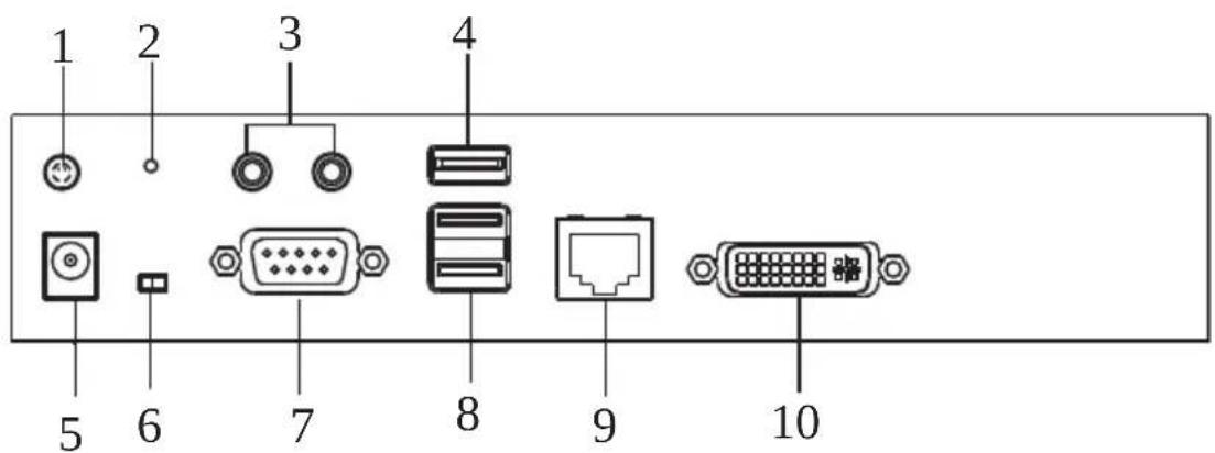
| No. | Component Description |
| 1 | GroundingTerminal |
| 2 | Reset This switch must be pushed with a thin object, such as the end of a paper clip.Press and release to reboot the device.Power off, hold reset then power on the device while pressing reset to recover from a firmware upgrade failure.Press and hold it in for more then three seconds resets the unit back to its factory default settings*.Note: The Reset to Factory Default function resets everything but the login information (username/password) to the factory default settings. To reset the login information, refer to Reset All Information on page 329. |
| 3 | Audio Ports These mini stereo ports are for the local speakers (green) and microphone (pink). |
| 4 | USB Port Use this port for virtual media or a USB peripheral device.Note: 1. When using a USB disk plugged into this port, see USB Mode, page 203.2. This USB port does not support isochronous endpoints, therefore USB peripherals that stream audio or video data, such as speakers or webcams, will not work. |
| 5 | Power Jack The cable from the DC Power adapter connects here. |
| 6 | Function Switch Use this slide switch to set the unit's mode:Extension: Sets the device to use the normal TX to RX extension mode.RS-232 Config: The device is ready to be configured via serial commands through the RS-232 port. |
| 7 | RS-232 Port This RS-232 serial port is for connecting to a serial terminal. |
| 8 | Console Ports The unit's USB keyboard and USB mouse plug into these ports. When using a keyboard or mouse with special functions, see USB Mode, page 203. |
| 9 | LAN Port The cable that connects the unit to the LAN plugs in here. |
| 10 | DVI-I Output The cable from the local DVI monitor plugs in here. |
KE6900AT (Transmitter) Front View
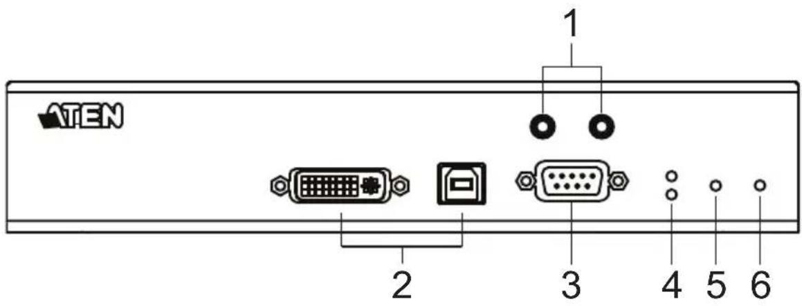
| No. | Component Description | |
| 1 | Audio Ports These mini stereo ports are for the speakers (green) and microphone (pink). | |
| 2 | KVM Ports The USB KVM cable supplied with the package that links the Transmitter to the computer plugs into these ports. | |
| 3 | RS-232 Port This RS-232 serial port is for connecting to the computer for serial control. | |
| 4 | Remote / Local LED Lights Green to indicate which side of the installation (Local or Remote) currently has KVM control of the computer. | |
| 5 | LAN LED This LED indicates the network status.◆ Lights when connected to the LAN and blinks when the Ethernet connection is active:◆ Orange: 10 Mbps◆ Orange + Green: 100 Mbps◆ Green: 1000 Mbps◆ Off when not connected to the LAN. | |
| 6 | Power LED Lights blue to indicate the unit is turned on. | |
KE6900AT (Transmitter) Rear View
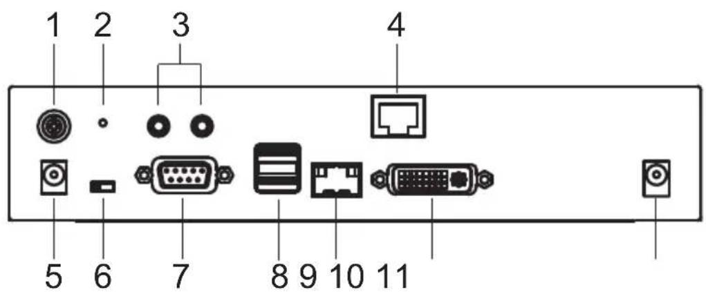
| No. | Component Description | ||
| 1 | Grounding Terminal The wire used to ground the unit connects here. | ||
| 2 | Reset This switch must be pushed with a thin object, such as the end of a paper clip.Press and release to reboot the device.Power off, hold reset then power on the device while pressing reset to recover from a firmware upgrade failure.Press and hold it in for more then three seconds resets the unit back to its factory default settings*.Note:The Reset to Factory Default function resets everything but the login information (username/password) to the factory default settings. To reset the login information, refer to Reset All Information on page 329. | ||
| 3 | Audio Ports These mini stereo ports are for the speakers (green) and microphone (pink). | ||
| 4 | LAN Port The cable that connects the unit to the LAN plugs in here. | ||
| 5 | Power Jack The cable from the DC Power adapter connects here. | ||
| 6 | Function Switch Use this slide switch to set the unit's mode to: | ||
| Serial port is for connecting to a serial terminal. | |||
| 7 RS-232 Port This RS-232 | |||
| 8 Console Ports The unit's USB keyboard and USB mouse plug into these ports. | |||
| 9 SFP Slot The Gigabit Ethernet (GbE) optical fiber cable that connects the unit to the LAN plugs in here. | |||
| 10 DVI-I Output The cable from the local DVI monitor plugs in here. | |||
| 11 Power Jack Connect a second power source for power redundancy. | |||
KE6900AR (Receiver) Front View
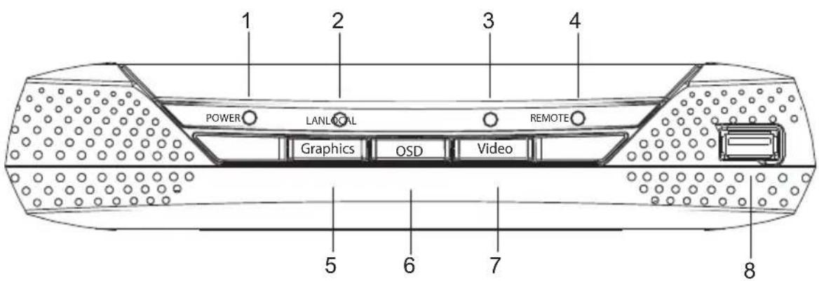
| No. | Component Description | |
| 1 | Power LED Lights blue to indicate the unit is turned on. | |
| 2 | LAN LED This LED indicates the network status.◆ Lights when connected to the LAN and blinks when the Ethernet connection is active:◆ Orange: 10 Mbps◆ Orange + Green: 100 Mbps◆ Green: 1000 Mbps◆ Off when not connected to the LAN. | |
| 3 | Local LED Lights green to Indicate the Transmitter has KVM access of the computer. | |
| 4 | Remote LED Lights green to Indicate the Receiver has KVM access of the computer. | |
| 5 | Graphics Pushbutton Sets the image quality of the display to the highest possible grade so that images are optimized. This toggle button turns off the Video Pushbutton option.Graphics mode is selected by default. | |
| 6 | OSD Pushbutton Use this pushbutton to open the OSD menu. | |
| 7 | Video Pushbutton Sets the image quality of the display to a grade that is optimized for playing videos. This toggle button turns off the Graphics Pushbutton option. | |
| 8 USB | Port Use this port for virtual media or a USB peripheral device.Note: 1. When using a USB disk plugged into this port, see USB Mode, page 203.2. This USB port does not support isochronous endpoints, therefore USB peripherals that stream audio or video data, such as speakers or webcams, will not work. | |
KE6900AR (Receiver) Rear View
| No. | Component Description |
| 1 | GroundingTerminal |
| 2 | Reset This switch must be pushed with a thin object, such as the end of a paper clip.Press and release to reboot the device.Power off, hold reset then power on the device while pressing reset to recover from a firmware upgrade failure.Press and hold it in for more then three seconds resets the unit back to its factory default settings*.Note:The Reset to Factory Default function resets everything but the login information (username/password) to the factory default settings. To reset the login information, refer to Reset All Information on page 329. |
| 3 | Audio Ports These mini stereo ports are for the local speakers (green) and microphone (pink). |
| 4 | USB Port Use this port for virtual media or a USB peripheral device.Note:1. When using a USB disk plugged into this port, see USB Mode, page 203.2. This USB port does not support isochronous endpoints, therefore USB peripherals that stream audio or video data, such as speakers or webcams, will not work. |
| 5 | SFP Slot The Gigabit Ethernet (GbE) optical fiber cable that connects the unit to the LAN plugs in here. |
| 6 | Power Jack The cable from the DC Power adapter connects here. |
| 7 Function Switch Use this slide switch to set the unit's mode:◆ Extension: Sets the device to use the normal TX to RX extension mode.◆ RS-232 Config: The device is ready to be configured via serial commands through the RS-232 port. | |
| 8 RS-232 Port This RS-232 serial port is for connecting to a serial terminal. | |
| 9 Console Ports The unit's USB keyboard and USB mouse plug into these ports. When using a keyboard or mouse with special functions, see USB Mode, page 203. | |
| 10 LAN Port The cable that connects the unit to the LAN plugs in here. | |
| 11 DVI-I Output The cable from the local DVI monitor plugs in here. | |
| 12 Power Jack Connect a second power source for power redundancy. | |
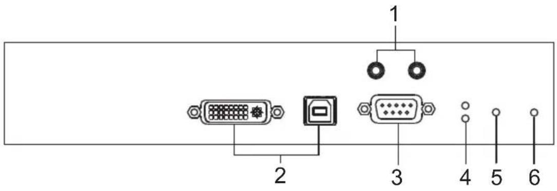
KE6910T / KE6912T (Transmitter) Front View
| No. | Component Description | |
| 1 | Audio Ports These mini stereo ports are for the speakers (green) and microphone (pink). | |
| 2 | KVM Ports The USB KVM cable supplied with the package that links the Transmitter to the computer plugs into these ports. | |
| 3 | RS-232 Port This RS-232 serial port is for connecting to the computer for serial control. | |
| 4 | Remote / Local LED Lights green to indicate which side of the installation (Local or Remote) has KVM control of the computer. | |
| 5 | LAN LED This LED indicates the network status.◆ Lights when connected to the LAN and blinks when the Ethernet connection is active:◆ Orange: 10 Mbps◆ Orange + Green: 100 Mbps◆ Green: 1000 Mbps◆ Off when not connected to the LAN. | |
| 6 | Power LED Lights blue to indicate the unit is turned on. | |
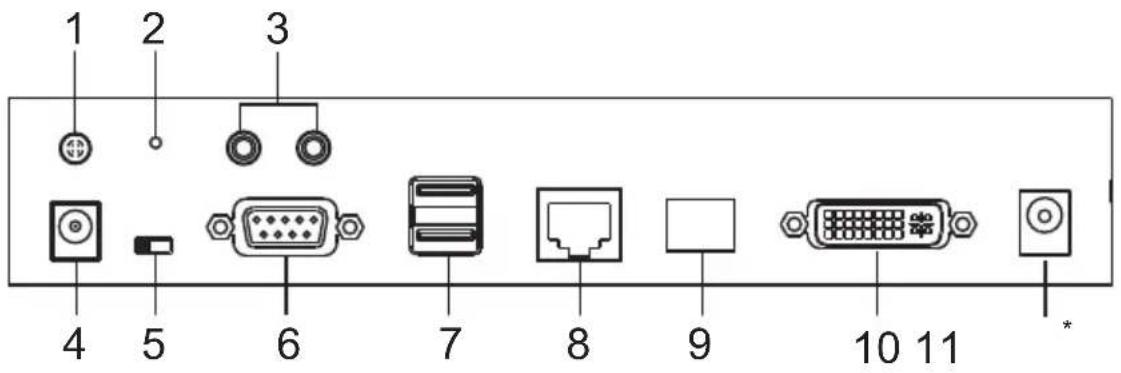
KE6910T / KE6912T (Transmitter) Rear View
| No. | Component Description | |
| 1 | Grounding Terminal The wire used to ground the unit connects here. | |
| 2 | Reset This switch must be pushed with a thin object, such as the end of a paper clip.Press and release to reboot the device.Power off, hold reset then power on the device while pressing reset to recover from a firmware upgrade failure.Press and hold it in for more then three seconds resets the unit back to its factory default settings*.Note:The Reset to Factory Default function resets everything but the login information (username/password) to the factory default settings. To reset the login information, refer to Reset All Information on page 329. | |
| 3 | Audio Ports These mini stereo ports are for the local speakers (green) and microphone (pink). | |
| 4 | Power Jack The cable from the DC Power adapter connects here. | |
| 5 | Function Switch Use this slide switch to set the unit's mode to:Auto: Shared (simultaneous) KVM control of the computer at the Transmitter and Receiver console.*RS-232 Config: The device is ready to be configured via serial commands through the RS-232 port. When connected to a KVM over IP Access Control Box (2XRT-0015G), users can enable / disable control privileges of the connected receivers.Local: Only the local Transmitter has KVM control of the computer. The Receiver's KVM access to the computer is locked.Note: In Auto mode, RS-232 and audio functions will work on the Receiver but not on the Transmitter. | |
| 6 RS-232 Port This RS-232 | serial port is for connecting to a serial terminal. | |
| 7 Console Ports The unit's USB keyboard and USB mouse plug into these ports. | ||
| 8 LAN Port The cable that connects the unit to the LAN plugs in here.This port is PoE enabled* for KE6912 for power redundancy or cable management.*Requires power board version B01G or later (see PoE Power Redundancy on page 69 for more details). | ||
| 9 SFP Slot The Gigabit Ethernet (GbE) optical fiber cable that connects the unit to the LAN plugs in here. | ||
| 10 DVI-D Output The cable from the local DVI monitor plugs in here. | ||
| 11 Power Jack (KE6910T only) | Connect a second power source for power redundancy. | |
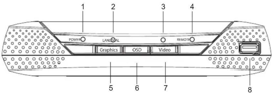
KE6910R / KE6912R (Receiver) Front View
| No. | Component Description | |
| 1 | Power LED Lights blue to indicate the unit is turned on. | |
| 2 | LAN LED This LED indicates the network status.◆Lights when connected to the LAN and blinks when the Ethernet connection is active:◆Orange: 10 Mbps◆Orange + Green: 100 Mbps◆Green: 1000 Mbps◆Off when not connected to the LAN. | |
| 3 | Local LED Lights green to indicate the Transmitter has KVM access of the computer. | |
| 4 | Remote LED Lights green to Indicate the Receiver has KVM access of the computer. | |
| 5 | Graphics Pushbutton Sets the image quality of the display to the highest possible grade so that images are optimized. This toggle button turns off the Video Pushbutton option.Graphics mode is selected by default. | |
| 6 | OSD Pushbutton Use this pushbutton to open the OSD menu. | |
| 7 | Video Pushbutton Sets the image quality of the display to a grade that is optimized for playing videos. This toggle button turns off the Graphics Pushbutton option. | |
| 8 | USB Port Use this port for virtual media or a USB peripheral device.Note:1. When using a USB disk plugged into this port, see USB Mode, page 203.2. This USB port does not support isochronous endpoints, therefore USB peripherals that stream audio or video data, such as speakers or webcams, will not work. | |
KE6910R / KE6912R (Receiver) Rear View
| No. | Component Description | |
| 1 | Grounding Terminal The wire used to ground the unit connects here. | |
| 2 | Reset This switch must be pushed with a thin object, such as the end of a paper clip.Press and release to reboot the device.Power off, hold reset then power on the device while pressing reset to recover from a firmware upgrade failure.Press and hold it in for more then three seconds resets the unit back to its factory default settings*.Note: The Reset to Factory Default function resets everything but the login information (username/password) to the factory default settings. To reset the login information, refer to Reset All Information on page 329. | |
| 3 | Audio Ports These mini stereo ports are for the local speakers (green) and microphone (pink). | |
| 4 | USB Port Use this port for virtual media or a USB peripheral device.Note: 1. When using a USB disk plugged into this port, see USB Mode, page 203.2. This USB port does not support isochronous endpoints, therefore USB peripherals that stream audio or video data, such as speakers or webcams, will not work. | |
| 5 | Power Jack The cable from the DC Power adapter connects here. | |
| 6 | Function Switch Use this slide switch to set the unit's mode:Extension: Sets the device to use the normal TX to RX extension mode.RS-232 Config: The device is ready to be configured via serial commands through the RS-232 port. | |
| 7 RS-232 Port This RS-232 | serial port is for connecting to a serial terminal. | |
| 8 Console Ports The unit's USB keyboard and USB mouse plug into these ports. | ||
| 9 LAN Port The cable that connects the unit to the LAN plugs in here.This port is PoE enabled* for KE6912 for power redundancy or cable management.*Requires power board version B01G or later (see PoE Power Redundancy on page 69 for more details). | ||
| 10 SFP Slot The Gigabit Ethernet (GbE) optical fiber cable that connects the unit to the LAN plugs in here. | ||
| 11 DVI-D Output The cable from the local DVI monitor plugs in here. | ||
| 12 Power Jack (KE6910R only) | Connect a second power source for power redundancy. | |
KE6920T / KE6922T (Transmitter) Front View
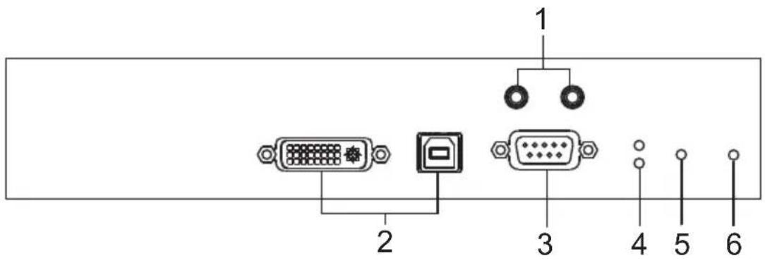
| No. | Component Description | |
| 1 | Audio Ports These mini stereo ports are for the speakers (green) and microphone (pink). | |
| 2 | KVM Ports The USB KVM cable supplied with the package that links the Transmitter to the computer plugs into these ports. | |
| 3 | RS-232 Port This RS-232 serial port is for connecting to the computer for serial control. | |
| 4 | Remote / Local LED Lights green to indicate which side of the installation (Local or Remote) has KVM control of the computer. | |
| 5 | LAN LED This LED indicates the network status.◆ Lights when connected to the LAN and blinks when the Ethernet connection is active:◆ Orange: 10 Mbps◆ Orange + Green: 100 Mbps◆ Green: 1000 Mbps◆ Off when not connected to the LAN. | |
| 6 | Power LED Lights blue to indicate the unit is turned on. | |
KE6920T / KE6922T (Transmitter) Rear View
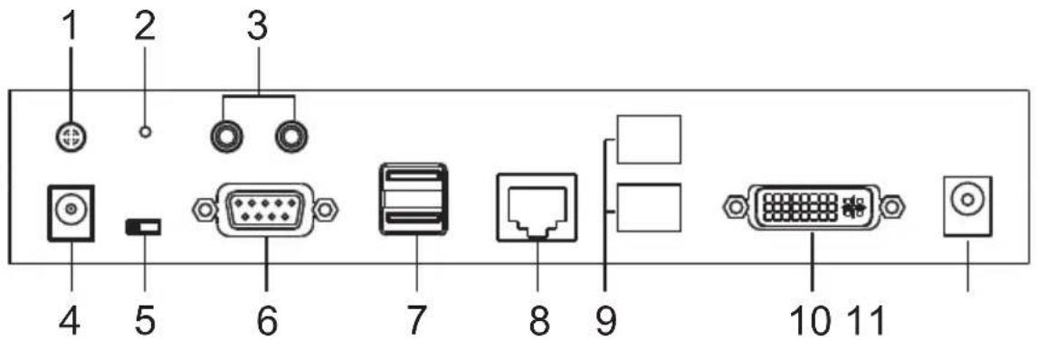
| No. | Component Description | |
| 1 | Grounding Terminal The wire used to ground the unit connects here. | |
| 2 | Reset This switch must be pushed with a thin object, such as the end of a paper clip.Press and release to reboot the device.Power off, hold reset then power on the device while pressing reset to recover from a firmware upgrade failure.Press and hold it in for more then three seconds resets the unit back to its factory default settings*.Note: The Reset to Factory Default function resets everything but the login information (username/password) to the factory default settings. To reset the login information, refer to Reset All Information on page 329. | |
| 3 | Audio Ports These mini stereo ports are for the local speakers (green) and microphone (pink). | |
| 4 | Power Jack The cable from the DC Power adapter connects here. | |
| 5 | Function Switch Use this slide switch to set the unit's mode to:Auto: Shared (simultaneous) KVM control of the computer at the Transmitter and Receiver console.*RS-232 Config: The device is ready to be configured via serial commands through the RS-232 port. When connected to a KVM over IP Access Control Box (2XRT-0015G), users can enable / disable control privileges of the connected receivers.Local: Only the local Transmitter has KVM control of the computer. The Receiver's KVM access to the computer is locked.Note: In Auto mode, RS-232 and audio functions will work on the Receiver but not on the Transmitter. | |
| No. | Component Description | |
| 6 RS | -232 Port This RS-232 serial port is for connecting to a serial terminal. | |
| 7 Console Ports The unit's USB | keyboard and USB mouse plug into these ports. | |
| 8 LAN | Port The cable that connects the unit to the LAN plugs in here.This port is PoE enabled* for KE6922 for power redundancy or cable management.*Requires power board version B01G or later (see PoE Power Redundancy on page 69 for more details). | |
| 9 SFP | Slots The Gigabit Ethernet (GbE) optical fiber cable that connects the unit to the LAN can be plugged here. | |
| 10 DVI-D Output The cable from the local DVI monitor plugs in here. | ||
| 11 Power Jack Connect a second | power source for power redundancy. | |
KE6920R / KE6922R (Receiver) Front View
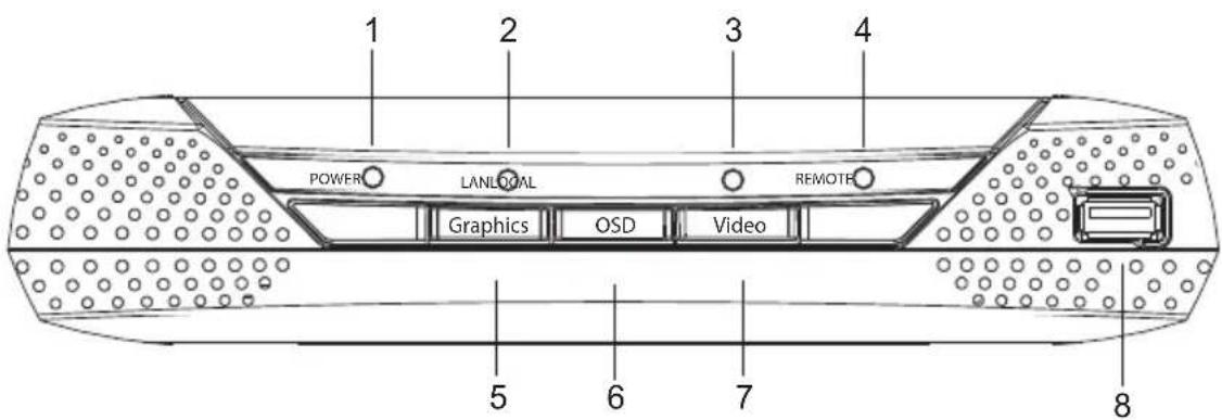
| No. | Component Description | |
| 1 | Power LED Lights blue to indicate the unit is turned on. | |
| 2 | LAN LED This LED indicates the network status.◆Lights when connected to the LAN and blinks when the Ethernet connection is active:◆Orange: 10 Mbps◆Orange + Green: 100 Mbps◆Green: 1000 Mbps◆Off when not connected to the LAN. | |
| 3 | Local LED Lights green to indicate the Transmitter has KVM access of the computer. | |
| 4 | Remote LED Lights green to Indicate the Receiver has KVM access of the computer. | |
| 5 | Graphics Pushbutton Sets the image quality of the display to the highest possible grade so that images are optimized. This toggle button turns off the Video Pushbutton option.Graphics mode is selected by default. | |
| 6 | OSD Pushbutton Use this pushbutton to open the OSD menu. | |
| 7 | Video Pushbutton Sets the image quality of the display to a grade that is optimized for playing videos. This toggle button turns off the Graphics Pushbutton option. | |
| 8 | USB Port Use this port for virtual media or a USB peripheral device.Note:1. When using a USB disk plugged into this port, see USB Mode, page 203.2. This USB port does not support isochronous endpoints, therefore USB peripherals that stream audio or video data, such as speakers or webcams, will not work. | |
KE6920R / KE6922R (Receiver) Rear View
| No. | Component Description | |
| 1 | Grounding Terminal The wire used to ground the unit connects here. | |
| 2 | Reset This switch must be pushed with a thin object, such as the end of a paper clip.Press and release to reboot the device.Power off, hold reset then power on the device while pressing reset to recover from a firmware upgrade failure.Press and hold it in for more then three seconds resets the unit back to its factory default settings*.Note: The Reset to Factory Default function resets everything but the login information (username/password) to the factory default settings. To reset the login information, refer to Reset All Information on page 329. | |
| 3 | Audio Ports These mini stereo ports are for the local speakers (green) and microphone (pink). | |
| 4 | USB Port Use this port for virtual media or a USB peripheral device.Note: 1. When using a USB disk plugged into this port, see USB Mode, page 203.2. This USB port does not support isochronous endpoints, therefore USB peripherals that stream audio or video data, such as speakers or webcams, will not work. | |
| 5 | Power Jack The cable from the DC Power adapter connects here. | |
| 6 | Function Switch Use this slide switch to set the unit's mode:Extension: Sets the device to use the normal TX to RX extension mode.RS-232 Config: The device is ready to be configured via serial commands through the RS-232 port. | |
| 7 RS | -232 Port This RS-232 | serial port is for connecting to a serial terminal. |
| 8 Console Ports The unit's USB keyboard and USB mouse plug into these ports. | ||
| 9 LAN | Port The cable that connects the unit to the LAN plugs in here.This port is PoE enabled* for KE6922 for power redundancy or cable management.*Requires power board version B01G or later (see PoE Power Redundancy on page 69 for more details). | |
| 10 SFP Slots The Gigabit Ethernet (GbE) optical fiber cable that connects the unit to the LAN can be plugged here. | ||
| 11 DVI-D Output The cable from the local DVI monitor plugs in here. | ||
| 12 Power Jack Connect a second power source for power redundancy. | ||
KE6940T (Transmitter) Front View
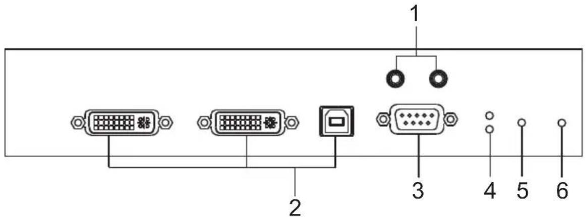
| No. | Component Description | |
| 1 | Audio Ports These mini ster | ereo ports are for the speakers (green) and microphone (pink). |
| 2 | KVM Ports The USB KVM | cable supplied with the package that links the Transmitter to the computer plugs into these ports. |
| 3 | RS-232 Port This RS-232 | serial port is for connecting to the computer for serial control. |
| 4 | Remote / Local LED Lights | green to indicate which side of the installation (Local or Remote) has KVM control of the computer. |
| 5 | LAN LED This LED indicates the network status.◆ Lights when connected to the LAN and blinks when the Ethernet connection is active:◆ Orange: 10 Mbps◆ Orange + Green: 100 Mbps◆ Green: 1000 Mbps◆ Off when not connected to the LAN. | |
| 6 | Power LED Lights blue to indicate the unit is turned on. | |
KE6940T (Transmitter) Rear View
| No. | Component Description | |
| 1 | Grounding Terminal The wire used to ground the unit connects here. | |
| 2 | Reset This switch must be pushed with a thin object, such as the end of a paper clip.Press and release to reboot the device.Power off, hold reset then power on the device while pressing reset to recover from a firmware upgrade failure.Press and hold it in for more then three seconds resets the unit back to its factory default settings*.Note:The Reset to Factory Default function resets everything but the login information (username/password) to the factory default settings. To reset the login information, refer to Reset All Information on page 329. | |
| 3 | Audio Ports These mini stereo ports are for the local speakers (green) and microphone (pink). | |
| 4 | Power Jack The cable from the DC Power adapter connects here. | |
| 5 | Function Switch Use this slide switch to set the unit's mode to:Auto: Shared (simultaneous) KVM control of the computer at the Transmitter and Receiver console.*RS-232 Config: The device is ready to be configured via serial commands through the RS-232 port. When connected to a KVM over IP Access Control Box (2XRT-0015G), users can enable / disable control privileges of the connected receivers.Local: Only the local Transmitter has KVM control of the computer. The Receiver's KVM access to the computer is locked.Note: In Auto mode, RS-232 and audio functions will work on the Receiver but not on the Transmitter. | |
| No. | Component Description | |
| 6 RS | -232 Port This RS-232 serial port is for connecting to a serial terminal. | |
| 7 Console Ports The unit's USB keyboard and USB mouse plug into these ports. | ||
| 8 LAN | Port The cable that connects the unit to the LAN plugs in here. | |
| 9 DVI-I Output The cable from the local DVI monitor plugs in here. | ||
KE6940R (Receiver) Front View
| No. | Component Description | |
| 1 | Power LED Lights blue to indicate the unit is turned on. | |
| 2 | LAN LED This LED indicates the network status.◆ Lights when connected to the LAN and blinks when the Ethernet connection is active:◆ Orange: 10 Mbps◆ Orange + Green: 100 Mbps◆ Green: 1000 Mbps◆ Off when not connected to the LAN. | |
| 3 | Local LED Lights green to indicate the Transmitter has KVM access of the computer. | |
| 4 | Remote LED Lights green to Indicate the Receiver has KVM access of the computer. | |
| 5 | Graphics Pushbutton Sets the image quality of the display to the highest possible grade so that images are optimized. This toggle button turns off the Video Pushbutton option.Graphics mode is selected by default. | |
| 6 | OSD Pushbutton Use this pushbutton to open the OSD menu. | |
| 7 | Video Pushbutton Sets the image quality of the display to a grade that is optimized for playing videos. This toggle button turns off the Graphics Pushbutton option. | |
| 8 USB Port Use this port for virtual media or a USB peripheral device.Note: 1. When using a USB disk plugged into this port, see USB Mode, page 203.2. This USB port does not support isochronous endpoints, therefore USB peripherals that stream audio or video data, such as speakers or webcams, will not work. | ||
KE6940R (Receiver) Rear View
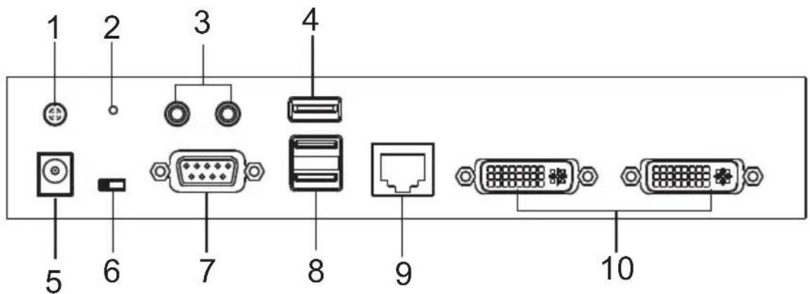
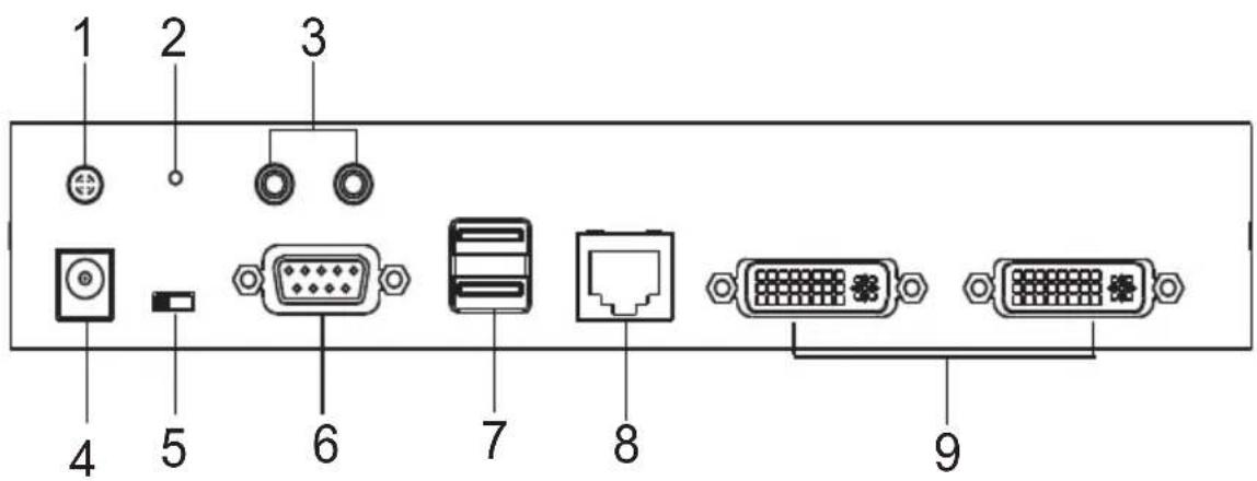
| No. | Component Description | |
| 1 | Grounding Terminal | The wire used to ground the unit connects here. |
| 2 | Reset This switch must | be pushed with a thin object, such as the end of a paper clip.Press and release to reboot the device.Power off, hold reset then power on the device while pressing reset to recover from a firmware upgrade failure.Press and hold it in for more then three seconds resets the unit back to its factory default settings*.Note:The Reset to Factory Default function resets everything but the login information (username/password) to the factory default settings. To reset the login information, refer to Reset All Information on page 329. |
| 3 | Audio Ports These mini | stereo ports are for the local speakers (green) and microphone (pink). |
| 4 | USB Port Use this port | for virtual media or a USB peripheral device.Note:1. When using a USB disk plugged into this port, see USB Mode, page 203.2. This USB port does not support isochronous endpoints, therefore USB peripherals that stream audio or video data, such as speakers or webcams, will not work. |
| 5 | Power Jack The cable | from the DC Power adapter connects here. |
| 6 | Function Switch Use this | slide switch to set the unit's mode:Extension: Sets the device to use the normal TX to RX extension mode.RS-232 Config: The device is ready to be configured via serial commands through the RS-232 port. |
| No. | Component Description |
| 7 RS-232 | Port This RS-232 serial port is for connecting to a serial terminal. |
| 8 Console Ports The unit | s USB keyboard and USB mouse plug into these ports. |
| 9 LAN Port The cable that connects the unit to the LAN plugs in here. | |
| 10 DVI-I Output The cable | from the local DVI monitors plug in here. |
KE6940AT (Transmitter) Front View
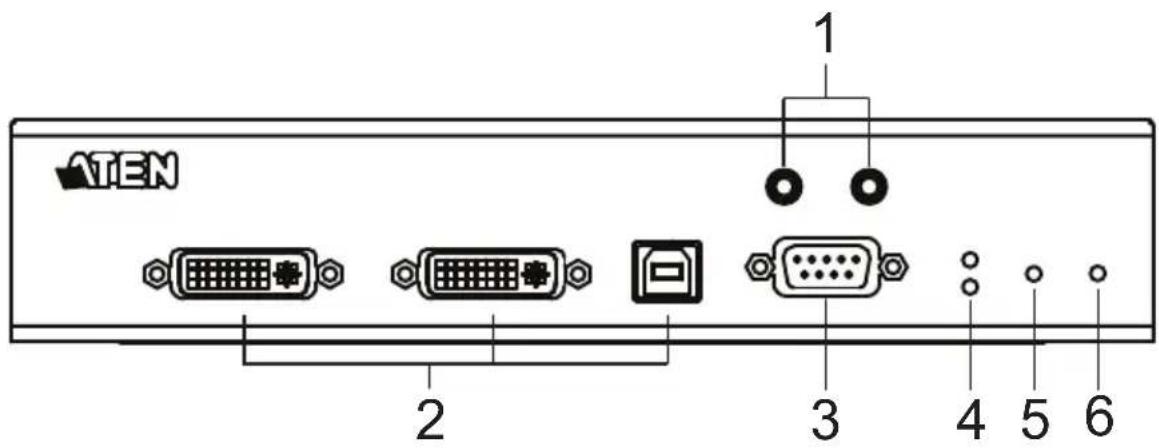
| No. | Component Description | |
| 1 | Audio Ports These mini stereo ports are for the speakers (green) and microphone (pink). | |
| 2 | KVM Ports The USB KVM cable and the DVI cable supplied with the package plugs into these ports to link the Transmitter to the computer. | |
| 3 | RS-232 Port This RS-232 serial port is for connecting to the computer for serial control. | |
| 4 | Remote / Local LED Lights Green to indicate which side of the installation (Local or Remote) currently has KVM control of the computer. | |
| 5 | LAN LED This LED indicates the network status.◆ Lights when connected to the LAN and blinks when the Ethernet connection is active:◆ Orange: 10 Mbps◆ Orange + Green: 100 Mbps◆ Green: 1000 Mbps◆ Off when not connected to the LAN. | |
| 6 | Power LED Lights blue to indicate the unit is turned on. | |
KE6940AT (Transmitter) Rear View
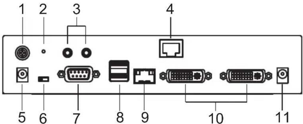
| No. | Component Description | ||
| 1 | Grounding Terminal The wire used to ground the unit connects here. | ||
| 2 | Reset This switch must be pushed with a thin object, such as the end of a paper clip.Press and release to reboot the device.Power off, hold reset then power on the device while pressing reset to recover from a firmware upgrade failure.Press and hold it in for more then three seconds resets the unit back to its factory default settings*.Note:The Reset to Factory Default function resets everything but the login information (username/password) to the factory default settings. To reset the login information, refer to Reset All Information on page 329. | ||
| 3 | Audio Ports These mini stereo ports are for the speakers (green) and microphone (pink). | ||
| 4 | LAN Port The cable that connects the unit to the LAN plugs in here. | ||
| 5 | Power Jack The cable from the DC Power adapter connects here. | ||
| 6 | Function Switch Use this slide switch to set the unit's mode to: | ||
| Serial port is for connecting to a serial terminal. | |||
| 7 RS-232 Port This RS-232 | |||
| 8 Console Ports The unit's USB keyboard and USB mouse plug into these ports. | |||
| 9 SFP Slot The Gigabit Ethernet (GbE) optical fiber cable that connects the unit to the LAN plugs in here. | |||
| 10 DVI-I Output The cables from the local DVI monitors plug in here. | |||
| 11 Power Jack Connect a second power source for power redundancy. | |||
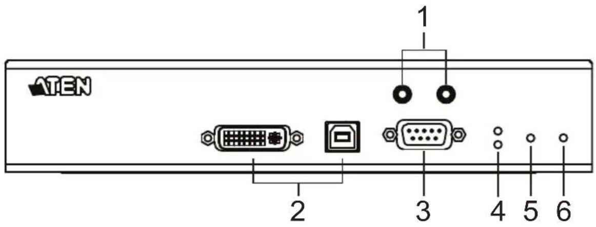
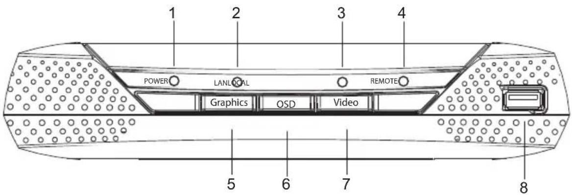
KE6940AR (Receiver) Front View
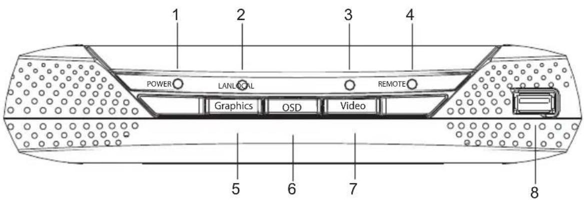
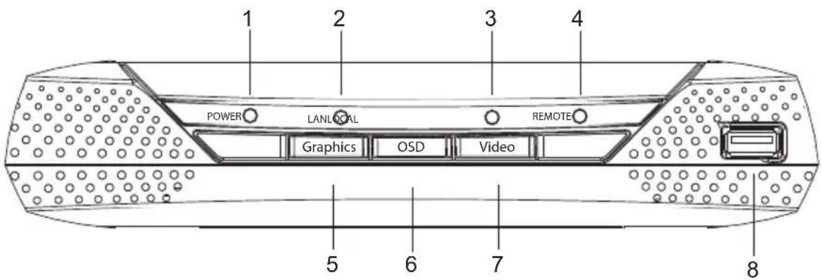
| No. | Component Description | |
| 1 | Power LED Lights blue to indicate the unit is turned on. | |
| 2 | LAN LED This LED indicates the network status.◆ Lights when connected to the LAN and blinks when the Ethernet connection is active:◆ Orange: 10 Mbps◆ Orange + Green: 100 Mbps◆ Green: 1000 Mbps◆ Off when not connected to the LAN. | |
| 3 | Local LED Lights green to Indicate the Transmitter has KVM access of the computer. | |
| 4 | Remote LED Lights green to Indicate the Receiver has KVM access of the computer. | |
| 5 | Graphics Pushbutton Sets the image quality of the display to the highest possible grade so that images are optimized. This toggle button turns off the Video Pushbutton option.Graphics mode is selected by default. | |
| 6 | OSD Pushbutton Use this pushbutton to open the OSD menu. | |
| 7 | Video Pushbutton Sets the image quality of the display to a grade that is optimized for playing videos. This toggle button turns off the Graphics Pushbutton option. | |
| 8 USB | Port Use this port for virtual media or a USB peripheral device.Note: 1. When using a USB disk plugged into this port, see USB Mode, page 203.2. This USB port does not support isochronous endpoints, therefore USB peripherals that stream audio or video data, such as speakers or webcams, will not work. | |
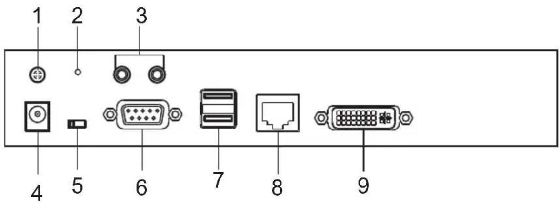
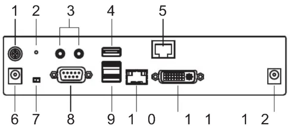
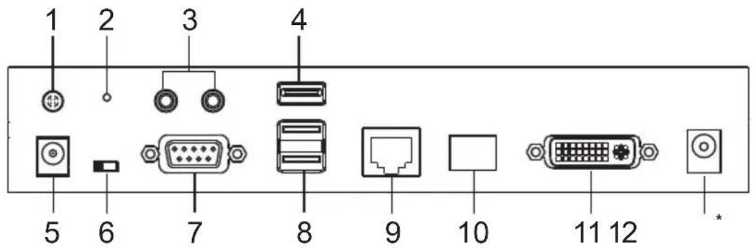
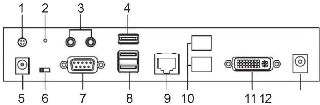
KE6940AR (Receiver) Rear View
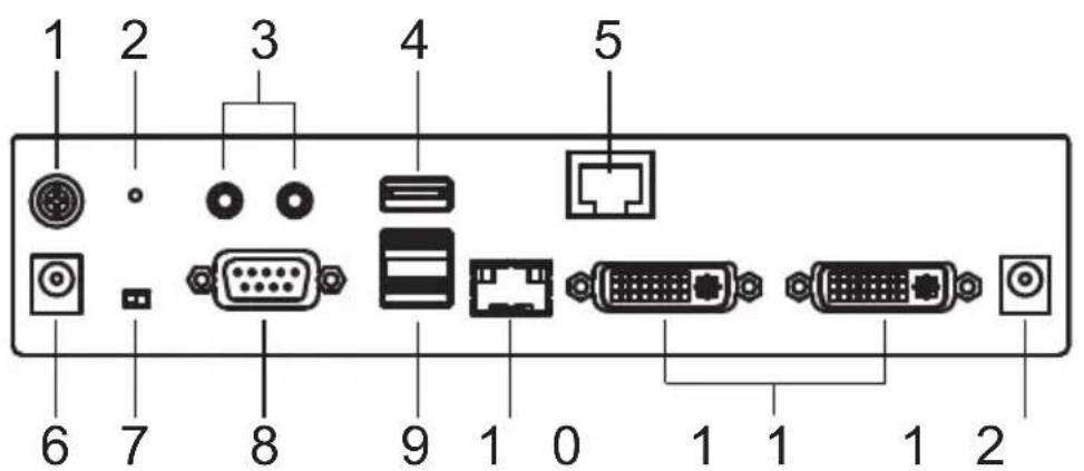
| No. | Component Description |
| 1 | GroundingTerminal |
| 2 | Reset This switch must be pushed with a thin object, such as the end of a paper clip.Press and release to reboot the device.Power off, hold reset then power on the device while pressing reset to recover from a firmware upgrade failure.Press and hold it in for more then three seconds resets the unit back to its factory default settings*.Note: The Reset to Factory Default function resets everything but the login information (username/password) to the factory default settings. To reset the login information, refer to Reset All Information on page 329. |
| 3 | Audio Ports These mini stereo ports are for the local speakers (green) and microphone (pink). |
| 4 | USB Port Use this port for virtual media or a USB peripheral device.Note: 1. When using a USB disk plugged into this port, see USB Mode, page 203.2. This USB port does not support isochronous endpoints, therefore USB peripherals that stream audio or video data, such as speakers or webcams, will not work. |
| 5 | SFP Slot The Gigabit Ethernet (GbE) optical fiber cable that connects the unit to the LAN plugs in here. |
| 6 | Power Jack The cable from the DC Power adapter connects here. |
| 7 Function Switch Use this slide switch to set the unit's mode:◆ Extension: Sets the device to use the normal TX to RX extension mode.◆ RS-232 Config: The device is ready to be configured via serial commands through the RS-232 port. | |
| 8 RS-232 Port This RS-232 serial port is for connecting to a serial terminal. | |
| 9 Console Ports The unit's USB keyboard and USB mouse plug into these ports. When using a keyboard or mouse with special functions, see USB Mode, page 203. | |
| 10 LAN Port The cable that connects the unit to the LAN plugs in here. | |
| 11 DVI-I Output The cables from the local DVI monitors plug in here. | |
| 12 Power Jack Connect a second power source for power redundancy. | |
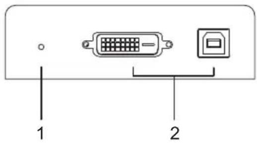
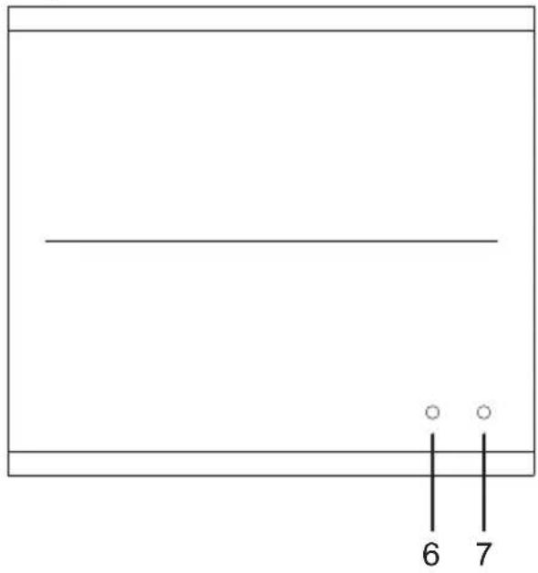
KE6900ST (Transmitter) Front, Rear and Top View
Front View
Top View
Rear View
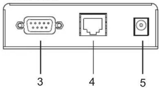
No. Component Description
| 1 Reset This switch must be pushed with a thin object, such as the end of a paper clip.◆ Press and release to reboot the device.◆ Power off, hold reset then power on the device while pressing reset to recover from a firmware upgrade failure.◆ Press and hold it in for more then three seconds resets the unit back to its factory default settings*.Note: The Reset to Factory Default function resets everything but the login information (username/password) to the factory default settings. To reset the login information, refer to Reset All Information on page 329. | |
| 2 KVM Port The USB KVM | cable supplied with the package that links the Transmitter to the computer plugs into these ports. |
| 3 RS-232 Port This RS-232 | serial port is for connecting to the computer for serial control.Note: When a LAN connection is detected serial commands bypass the KE6900ST and are sent across the network to the receiver. When no LAN connection is detected serial commands are automatically directed to the KE6900ST for local configuration and control. |
| 4 LAN Port The cable that | connects the unit to the LAN plugs in here. |
| No. | Component Description |
| 5 | Power Jack The cable from the DC Power adapter connects here. |
| 6 | LAN LED This LED indicates the network status.Lights when connected to the LAN and blinks when the Ethernet connection is active:Orange: 10 MbpsOrange + Green: 100 MbpsGreen: 1000 MbpsOff when not connected to the LAN. |
| 7 | Power LED Lights blue to indicate the unit is turned on. |
KE8950T / KE8952T (Transmitter) Front View
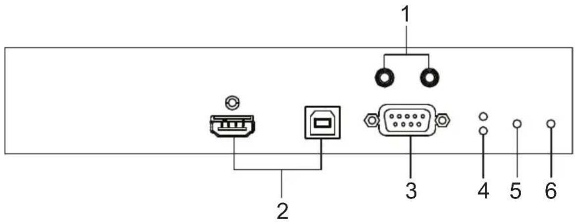
| No. | Component Description | |
| 1 | Audio Ports These mini ster | reo ports are for the speakers (green) and microphone (pink). |
| 2 | KVM Ports The USB KVM | cable supplied with the package that links the Transmitter to the computer plugs into these ports. |
| 3 | RS-232 Port This RS-232 | serial port is for connecting to the computer for serial control. |
| 4 | Remote / Local LED Lights | Green to indicate which side of the installation (Local or Remote) currently has KVM control of the computer. |
| 5 | LAN LED This LED indicates | the network status.◆ Lights when connected to the LAN and blinks when the Ethernet connection is active:◆ Orange: 10 Mbps◆ Orange + Green: 100 Mbps◆ Green: 1000 Mbps◆ Off when not connected to the LAN. |
| 6 | Power LED Lights blue to | indicate the unit is turned on. |
KE8950T / KE8952T (Transmitter) Rear View
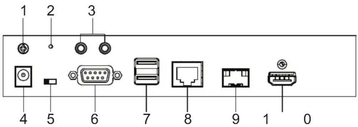
| No. | Component Description | |
| 1 | Grounding Terminal The wire used to ground the unit connects here. | |
| 2 | Reset This switch must be pushed with a thin object, such as the end of a paper clip.Press and release to reboot the device.Power off, hold reset then power on the device while pressing reset to recover from a firmware upgrade failure.Press and hold it in for more then three seconds resets the unit back to its factory default settings*.Note: The Reset to Factory Default function resets everything but the login information (username/password) to the factory default settings. To reset the login information, refer to Reset All Information on page 329. | |
| 3 | Audio Ports These mini stereo ports are for the speakers (green) and microphone (pink). | |
| 4 | Power Jack The cable from the DC Power adapter connects here. | |
| 5 | Function Switch Use this slide switch to set the unit's mode to:Auto: Shared (simultaneous) KVM control of the computer at the Transmitter and Receiver console.*RS-232 Config: The device is ready to be configured via serial commands through the RS-232 port. When connected to a KVM over IP Access Control Box (2XRT-0015G), users can enable / disable control privileges of the connected receivers.Local: Only the local Transmitter has KVM control of the computer. The Receiver's KVM access to the computer is locked.Note: In Auto mode, RS-232 and audio functions will work on the Receiver but not on the Transmitter. | |
| No. | Component Description | |
| 6 RS | -232 Port This RS-232 serial port is for connecting to a serial terminal. | |
| 7 Console Ports The unit's USB keyboard and USB mouse plug into these ports. | ||
| 8 LAN | Port The cable that connects the unit to the LAN plugs in here.This port is PoE enabled* for KE8952 for power redundancy or cable management.*Requires power board version B01G or later (see PoE Power Redundancy on page 69 for more details). | |
| 9 SFP | Port The Gigabit Ethernet (GbE) optical fiber cable that connects the unit to the LAN plugs in here. | |
| 10 HDMI Output The cable from the local HDMI monitor plugs in here. | ||
KE8950R / KE8952R (Receiver) Front View
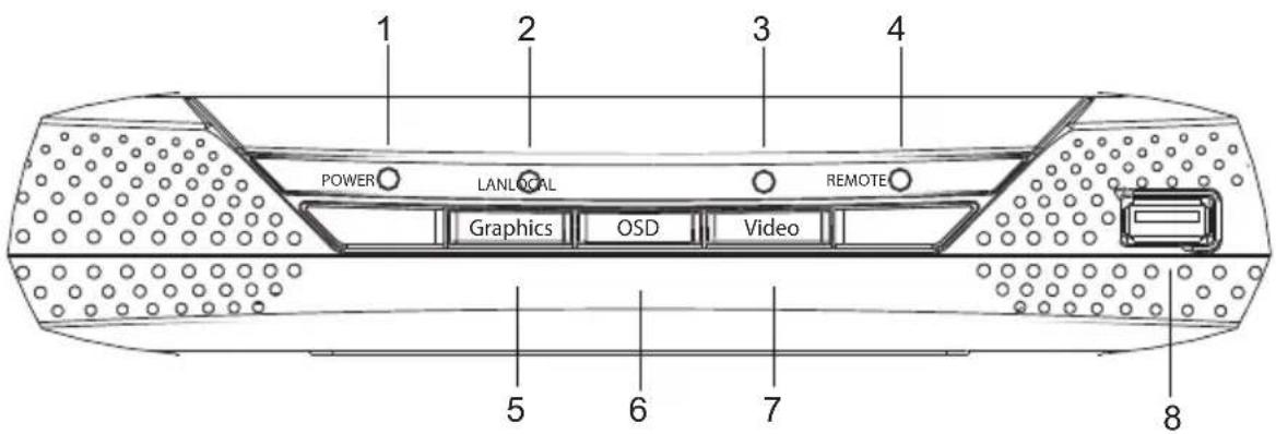
| No. | Component Description | |
| 1 | Power LED Lights blue to indicate the unit is turned on. | |
| 2 | LAN LED This LED indicates the network status.◆ Lights when connected to the LAN and blinks when the Ethernet connection is active:◆ Orange: 10 Mbps◆ Orange + Green: 100 Mbps◆ Green: 1000 Mbps◆ Off when not connected to the LAN. | |
| 3 | Local LED Lights green to indicate the Transmitter has KVM access of the computer. | |
| 4 | Remote LED Lights green to Indicate the Receiver has KVM access of the computer. | |
| 5 | Graphics Pushbutton Sets the image quality of the display to the highest possible grade so that images are optimized. This toggle button turns off the Video Pushbutton option.Graphics mode is selected by default. | |
| 6 | OSD Pushbutton Use this pushbutton to open the OSD menu. | |
| 7 | Video Pushbutton Sets the image quality of the display to a grade that is optimized for playing videos. This toggle button turns off the Graphics Pushbutton option. | |
| 8 USB Port Use this port for virtual media or a USB peripheral device.Note: 1. When using a USB disk plugged into this port, see USB Mode, page 203.2. This USB port does not support isochronous endpoints, therefore USB peripherals that stream audio or video data, such as speakers or webcams, will not work. | ||
KE8950R / KE8952R (Receiver) Rear View
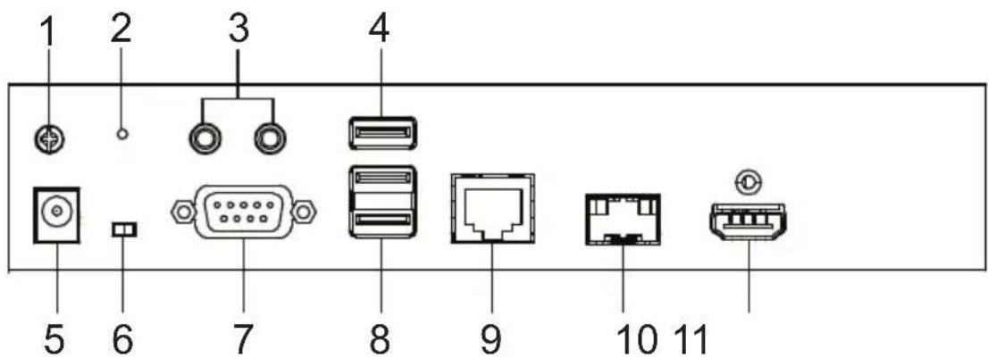
| No. | Component Description |
| 1 | GroundingTerminal |
| 2 | Reset This switch must be pushed with a thin object, such as the end of a paper clip.Press and release to reboot the device.Power off, hold reset then power on the device while pressing reset to recover from a firmware upgrade failure.Press and hold it in for more then three seconds resets the unit back to its factory default settings*.Note:The Reset to Factory Default function resets everything but the login information (username/password) to the factory default settings. To reset the login information, refer to Reset All Information on page 329. |
| 3 | Audio Ports These mini stereo ports are for the local speakers (green) and microphone (pink). |
| 4 | USB Port Use this port for virtual media or a USB peripheral device.Note:1. When using a USB disk plugged into this port, see USB Mode, page 203.2. This USB port does not support isochronous endpoints, therefore USB peripherals that stream audio or video data, such as speakers or webcams, will not work. |
| 5 | Power Jack The cable from the DC Power adapter connects here. |
| 6 | Function Switch Use this slide switch to set the unit's mode:Extension: Sets the device to use the normal TX to RX extension mode.RS-232 Config: The device is ready to be configured via serial commands through the RS-232 port. |
| 7 | RS-232 Port This RS-232 serial port is for connecting to a serial terminal. |
| 8 | Console Ports The unit's USB keyboard and USB mouse plug into these ports. When using a keyboard or mouse with special functions, see USB Mode, page 203. |
| 9 | LAN Port The cable that connects the unit to the LAN plugs in here.This port is PoE enabled* for KE8952 for power redundancy or cable management.*Requires power board version B01G or later (see PoE Power Redundancy on page 69 for more details). |
| 10 | SFP Port The Gigabit Ethernet (GbE) optical fiber cable that connects the unit to the LAN plugs in here. |
| 11 | HDMI Output The cable from the local HDMI monitor plugs in here. |
KE8900ST (Transmitter) Front, Rear and Side View
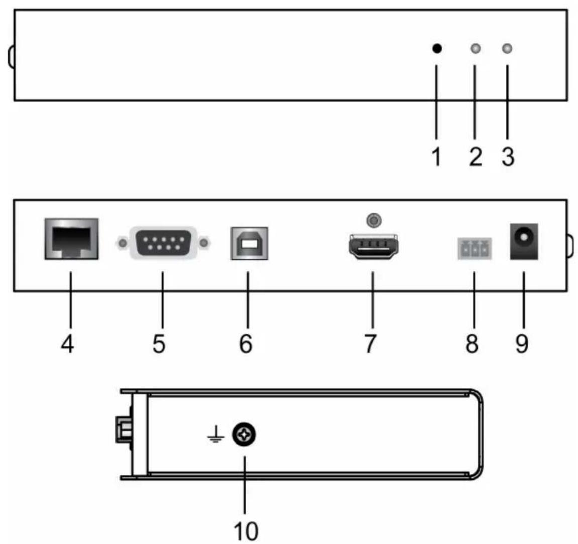
No. Component Description
1 Reset This switch must be pushed with a thin object, such as the end of a paper clip.
◆ Press and release to reboot the device.
Power off, hold reset then power on the device while pressing reset to recover from a firmware upgrade failure.
- Press and hold it in for more then three seconds resets the unit back to its factory default settings*.
Note: The Reset to Factory Default function resets everything but the login information (username/password) to the factory default settings. To reset the login information, refer to Reset All Information on page 329.
| No. | Component Description |
| 2 LAN | LED This LED indicates the network status.Lights when connected to the LAN and blinks when the Ethernet connection is active:Orange: 10 MbpsOrange + Green: 100 MbpsGreen: 1000 MbpsOff when not connected to the LAN. |
| 3 Power | LED Lights blue to indicate the unit is turned on. |
| 4 LAN | Port The cable that connects the unit to the LAN plugs in here. |
| 5 RS | -232 Port This RS-232 serial port is for connecting to the computer for serial control.Note:When a LAN connection is detected serial commands bypass the KE8900ST and are sent across the network to the receiver. When no LAN connection is detected serial commands are automatically directed to the KE8900ST for local configuration and control. |
| 6 USB | Type-B PortThe USB port that links the Transmitter to the computer . |
| 7 HDMI | Input The cable from the local HDMI monitor plugs in here. |
| 8 3-Pole | Terminal BlockInsert DC + and - wires (DC 12 to 48V) to the terminal block for power input. |
| 9 Power | Jack The cable from the DC Power adapter connects here. |
| 10 Grounding Terminal | TerminalThe wire used to ground the unit connects here. |
KE8900SR (Receiver) Front, Rear and Side View
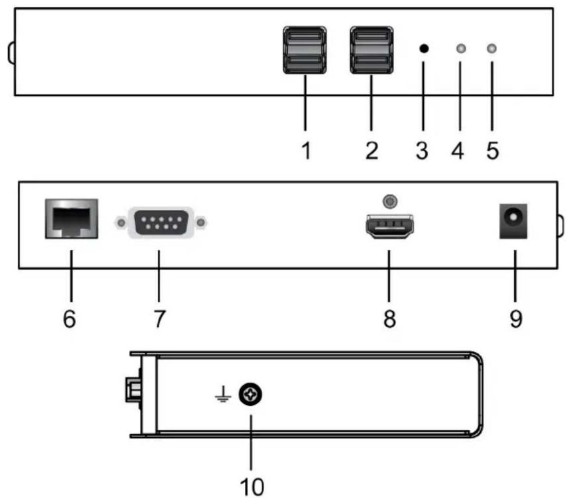
| No. | Component Description |
| 1 USB | Peripheral PortUse this port for virtual media or a USB peripheral device.Note: 1. When using a USB disk plugged into this port, see USB Mode, page 203.2. This USB port does not support isochronous endpoints, therefore USB peripherals that stream audio or video data, such as speakers or webcams, will not work. |
| 2 Console | Ports The unit's USB keyboard and USB mouse plug into these ports. |
| 3 | Reset This switch must be pushed with a thin object, such as the end of a paper clip.Press and release to reboot the device.Power off, hold reset then power on the device while pressing reset to recover from a firmware upgrade failure.Press and hold it in for more then three seconds resets the unit back to its factory default settings*.Note:The Reset to Factory Default function resets everything but the login information (username/password) to the factory default settings. To reset the login information, refer to Reset All Information on page 329. |
| 4 | LAN LED This LED indicates the network status.Lights when connected to the LAN and blinks when the Ethernet connection is active:Orange: 10 MbpsOrange + Green: 100 MbpsGreen: 1000 MbpsOff when not connected to the LAN. |
| 5 | Power LED Lights blue to indicate the unit is turned on. |
| 6 | LAN Port The cable that connects the unit to the LAN plugs in here. |
| 7 | RS-232 Port This RS-232 serial port is for connecting to the computer for serial control.Note:When a LAN connection is detected serial commands bypass the KE8900ST and are sent across the network to the receiver. When no LAN connection is detected serial commands are automatically directed to the KE8900ST for local configuration and control. |
| 8 | HDMI Output The cable from the local HDMI monitor plugs in here. |
| 9 | Power Jack The cable from the DC Power adapter connects here. |
| 10 | Grounding TerminalThe wire used to ground the unit connects here. |
KE9900ST (Transmitter) Front, Rear and Side View
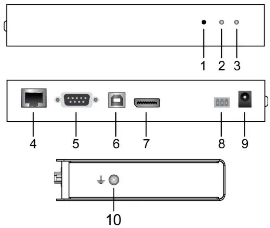
No. Component Description
1 Reset This switch must be pushed with a thin object, such as the end of a paper clip.
◆ Press and release to reboot the device.
- Power off, hold reset then power on the device while pressing reset to recover from a firmware upgrade failure.
- Press and hold it in for more then three seconds resets the unit back to its factory default settings*.
Note: The Reset to Factory Default function resets everything but the login information (username/password) to the factory default settings. To reset the login information, refer to Reset All Information on page 329.
| No. | Component Description | |
| 2 LAN | LED This LED indicates the network status.Lights when connected to the LAN and blinks when the Ethernet connection is active:Orange: 10 MbpsOrange + Green: 100 MbpsGreen: 1000 MbpsOff when not connected to the LAN. | |
| 3 Power | LED Lights blue to indicate the unit is turned on. | |
| 4 LAN | Port The cable that connects the unit to the LAN plugs in here. | |
| 5 RS | -232 Port This RS-232 serial port is for connecting to the computer for serial control.Note:When a LAN connection is detected serial commands bypass the KE8900ST and are sent across the network to the receiver. When no LAN connection is detected serial commands are automatically directed to the KE8900ST for local configuration and control. | |
| 6 USB | Type-B Port | The USB port that links the Transmitter to the computer. |
| 7 | D i s p Input | The cable from the Pocal Display Port monitor plugs in here. |
| 8 3-Pole Terminal Block | Insert DC + and - wires (DC 12 to 48V) to the terminal block for power input. | |
| 9 Power | Jack The cable from the DC Power adapter connects here. | |
| 10 Grounding Terminal | The wire used to ground the unit connects here. | |
KE9950T / KE9952T (Transmitter) Front View
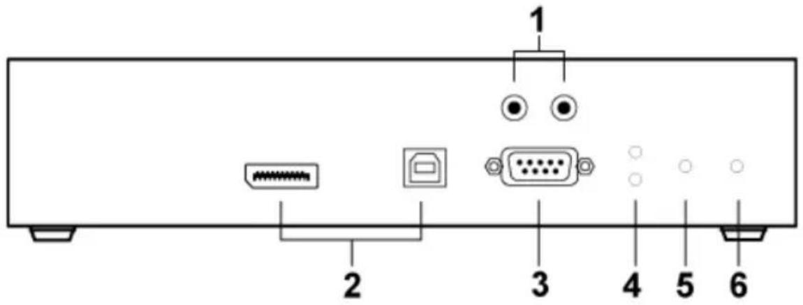
| No. | Component Description | |
| 1 | Audio Ports These mini stereo ports are for the speakers (green) and microphone (pink). | |
| 2 | KVM Ports The USB KVM cable supplied with the package that links the Transmitter to the computer plugs into these ports. | |
| 3 | RS-232 Port This RS-232 serial port is for connecting to the computer for serial control. | |
| 4 | Remote / Local LED Lights Green to indicate which side of the installation (Local or Remote) currently has KVM control of the computer. | |
| 5 | LAN LED This LED indicates the network status.◆ Lights when connected to the LAN and blinks when the Ethernet connection is active:◆ Orange: 10 Mbps◆ Orange + Green: 100 Mbps◆ Green: 1000 Mbps◆ Off when not connected to the LAN. | |
| 6 | Power LED Lights blue to indicate the unit is turned on. | |
KE9950T / KE9952T (Transmitter) Rear View
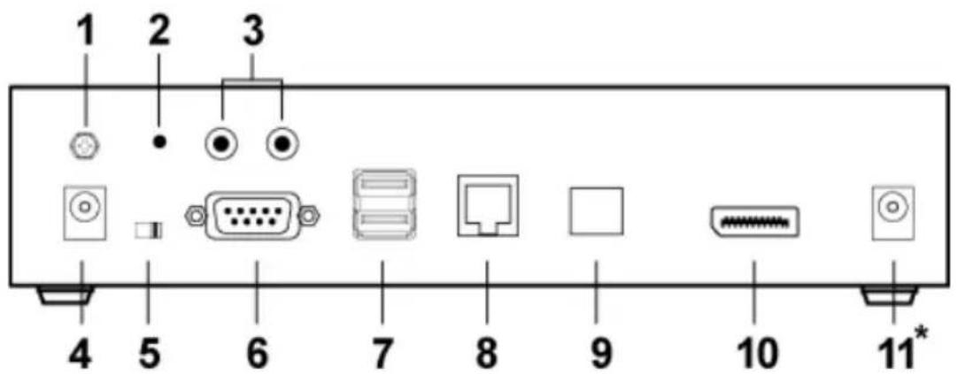
| No. | Component Description | |
| 1 | Grounding Terminal The wire used to ground the unit connects here. | |
| 2 | Reset This switch must be pushed with a thin object, such as the end of a paper clip.Press and release to reboot the device.Power off, hold reset then power on the device while pressing reset to recover from a firmware upgrade failure.Press and hold it in for more then three seconds resets the unit back to its factory default settings*.Note:The Reset to Factory Default function resets everything but the login information (username/password) to the factory default settings. To reset the login information, refer to Reset All Information on page 329. | |
| 3 | Audio Ports These mini stereo ports are for the local speakers (green) and microphone (pink). | |
| 4 | Power Jack The cable from the DC Power adapter connects here. | |
| 5 | Function Switch Use this side switch to set the unit's mode to:Auto: Shared (simultaneous) KVM control of the computer at the Transmitter and Receiver console.*RS-232 Config/Access Control: The device is ready to be configured via serial commands through the RS-232 port. When connected to a KVM over IP Access Control Box (2XRT-0015G), users can enable / disable control privileges of the connected receivers.Local: Only the local Transmitter has KVM control of the computer. The Receiver's KVM access to the computer is locked.Note: In Auto mode, RS-232 and audio functions will work on the Receiver but not on the Transmitter. | |
| 6 RS | -232 Port This RS-232 | serial port is for connecting to a serial terminal. |
| 7 Console Ports The unit's USB keyboard and USB mouse plug into these ports. | ||
| 8 LAN | Port The cable that connects the unit to the LAN plugs in here.This port is PoE enabled* for KE9952 for power redundancy or cable management.*Requires power board version B01G or later (see PoE Power Redundancy on page 69 for more details). | |
| 9 SFP | Slot The Gigabit Ethernet (GbE) optical fiber cable that connects the unit to the LAN plugs in here. | |
| 10 DisplayPort Output The cable from the local DisplayPort monitor plugs in here. | ||
| 11 Power Jack(KE9950T only) | Connect a second power source for power redundancy. | |
KE9950R / KE9952R (Receiver) Front View
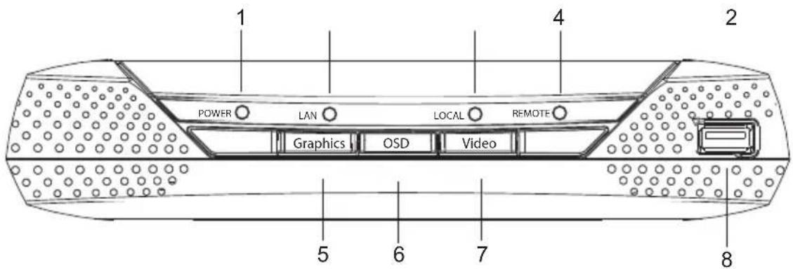
3
| No. | Component Description | |
| 1 | Power LED Lights blue to indicate the unit is turned on. | |
| 2 | LAN LED This LED indicates the network status.◆Lights when connected to the LAN and blinks when the Ethernet connection is active:◆Orange: 10 Mbps◆Orange + Green: 100 Mbps◆Green: 1000 Mbps◆Off when not connected to the LAN. | |
| 3 | Local LED Lights green to Indicate the Transmitter has KVM access of the computer. | |
| 4 | Remote LED Lights green to Indicate the Receiver has KVM access of the computer. | |
| 5 | Graphics Pushbutton Sets the image quality of the display to the highest possible grade so that images are optimized. This toggle button turns off the Video Pushbutton option.Graphics mode is selected by default. | |
| 6 | OSD Pushbutton Use this pushbutton to open the OSD menu. | |
| 7 | Video Pushbutton Sets the image quality of the display to a grade that is optimized for playing videos. This toggle button turns off the Graphics Pushbutton option. | |
| 8 | USB Port Use this port for virtual media or a USB peripheral device.Note:1. When using a USB disk plugged into this port, see USB Mode, page 203.2. This USB port does not support isochronous endpoints, therefore USB peripherals that stream audio or video data, such as speakers or webcams, will not work. | |
KE9950R / KE9952R (Receiver) Rear View
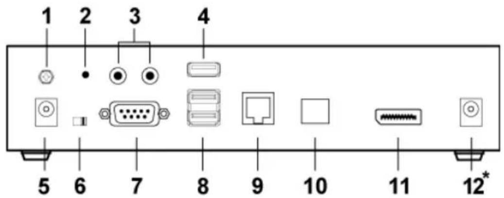
| No. | Component Description | |
| 1 | Grounding Terminal The wire used to ground the unit connects here. | |
| 2 | Reset This switch must be pushed with a thin object, such as the end of a paper clip.Press and release to reboot the device.Power off, hold reset then power on the device while pressing reset to recover from a firmware upgrade failure.Press and hold it in for more then three seconds resets the unit back to its factory default settings*.Note: The Reset to Factory Default function resets everything but the login information (username/password) to the factory default settings. To reset the login information, refer to Reset All Information on page 329. | |
| 3 | Audio Ports These mini stereo ports are for the local speakers (green) and microphone (pink). | |
| 4 | USB Port Use this port for virtual media or a USB peripheral device.Note: 1. When using a USB disk plugged into this port, see USB Mode, page 203.2. This USB port does not support isochronous endpoints, therefore USB peripherals that stream audio or video data, such as speakers or webcams, will not work. | |
| 5 | Power Jack The cable from the DC Power adapter connects here. | |
| 6 | Function Switch Use this slide switch to set the unit's mode:Extension: Sets the device to use the normal TX to RX extension mode.RS-232 Config: The device is ready to be configured via serial commands through the RS-232 port. | |
| 7 RS-232 Port This RS-232 | serial port is for connecting to a serial terminal. | |
| 8 Console Ports The unit's USB keyboard and USB mouse plug into these ports. | ||
| 9 LAN Port The cable that connects the unit to the LAN plugs in here.This port is PoE enabled* for KE9952 for power redundancy or cable management.*Requires power board version B01G or later (see PoE Power Redundancy on page 69 for more details). | ||
| 10 SFP Slot The Gigabit Ethernet (GbE) optical fiber cable that connects the unit to the LAN plugs in here. | ||
| 11 DisplayPort Output The cable from the local DisplayPort monitor plugs in here. | ||
| 12 Power Jack (KE9950R only) | Connect a second power source for power redundancy. | |
PoE Power Redundancy
For power redundancy with PoE-enabled models, the unit's underside label must be printed with a "Power Board Version: B01G" string. An example is shown below and the string is indicated in the diagram:
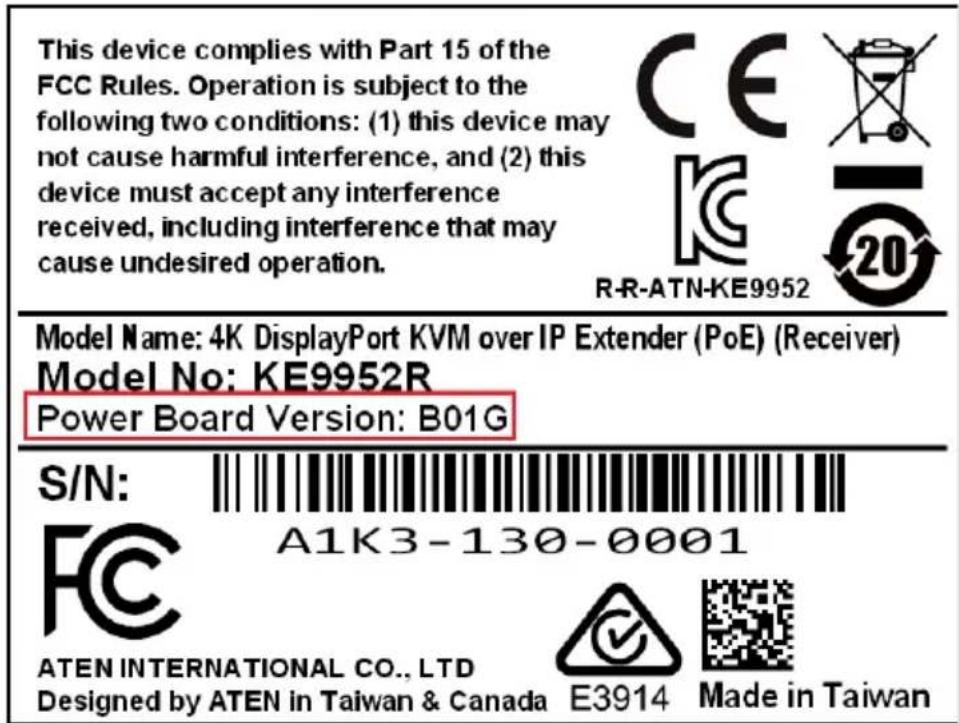
This Page Intentionally Left Blank
Chapter 2
Hardware Setup

-
Important safety information regarding the placement of this device is found on page 293. Please review it before proceeding.
-
Make sure that the power to all devices connected to the installation is turned off. You must unplug the power cords of any computers that have the Keyboard Power On function.
Mounting
For convenience and flexibility, the transmitters can be mounted on system racks or on a wall.
Note: Optional mounting options are available, refer to Optional Rack Mounting on page 320 for more information.
The following sections will demonstrate on how to mount the transmitters with the included mounting kit.
Attaching the Bracket
Follow the steps below to attach the mounting bracket to the unit:
Non-Slim Transmitters
Note: Steps for the non-slim transmitters (KE6900, KE6900A, KE6910, KE6912, KE6920, KE6922, KE6940, KE6940A, KE8950, KE8952, KE9950, and KE9952) are the same and KE6900 will be shown in the steps below.
- Unscrew the screws from the side shown in the diagram below:
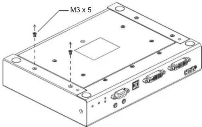
- Use the screws from step 1 to screw the mounting bracket to the bottom of the Transmitter as shown below:
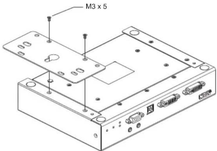
Slim Transmitters - KE6900ST
Using the screws provided in the Mounting Kit, screw the mounting bracket into the bottom of the Transmitter as show below:
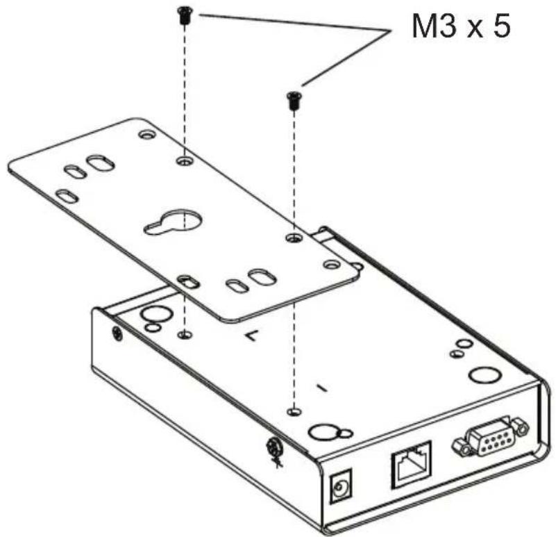
Slim Transmitters - KE8900ST / KE9900ST
KE8900ST is used in the diagrams below.
- Unscrew the screws from the side shown in the diagram below:
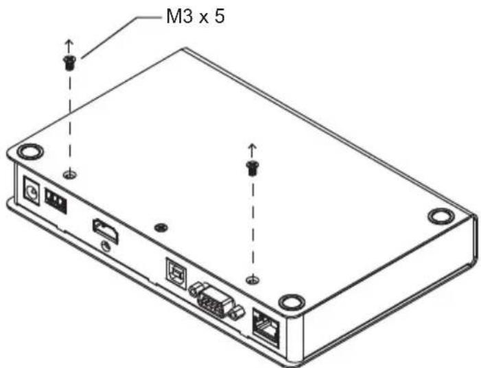
- Use the screws from step 1 to screw the mounting bracket to the bottom of the Transmitter as shown below:
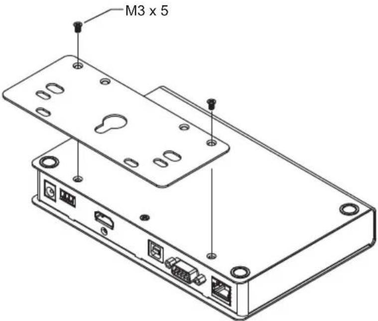
Rack Mount
Non-Slim Transmitters
Note: Steps for the non-slim transmitters (KE6900, KE6900A, KE6910, KE6912, KE6920, KE6922, KE6940, KE6940A, KE8950, KE8952, KE9950, and KE9952) are the same and KE6900 will be shown in the steps below.
Screw the bracket into a convenient location on the rack.
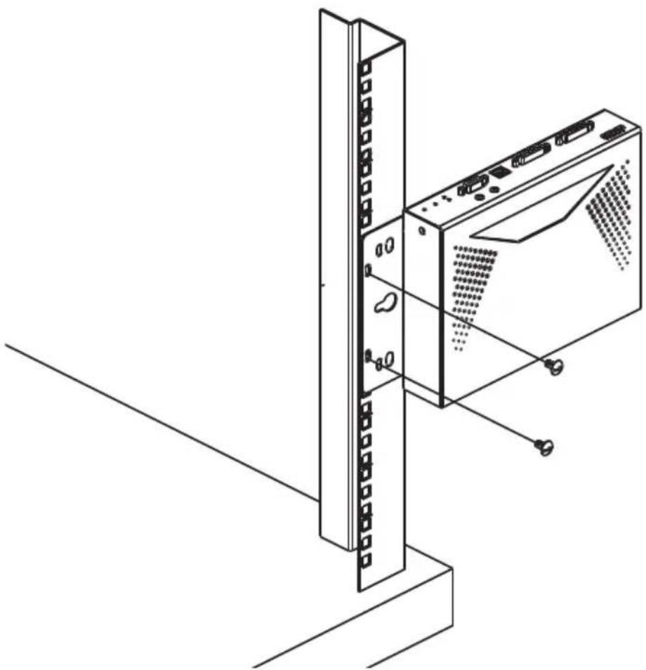
natural_image
Isometric line drawing of a server rack unit with attached device (no text or symbols)Note: Rack screws are not provided. We recommend that you use M5 x 12 Phillips Type I cross recessed type screws.
Slim Transmitters - KE6900ST
Screw the bracket into a convenient location on the rack.
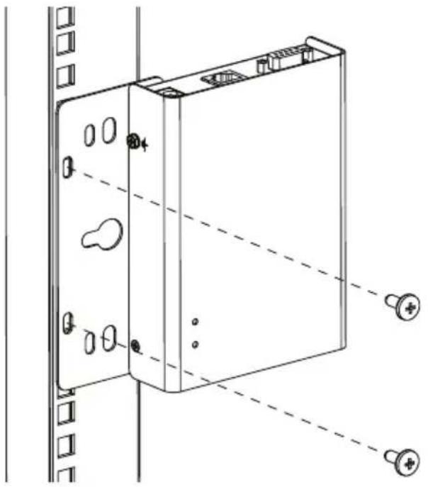
natural_image
Technical line drawing of a mechanical device with mounting holes and mounting screws (no text or symbols)Note: Rack screws are not provided. We recommend that you use M5 x 12 Phillips Type I cross recessed type screws.
Slim Transmitters - KE8900ST / KE9900ST
Screw the mounting bracket to any convenient location on the rack.
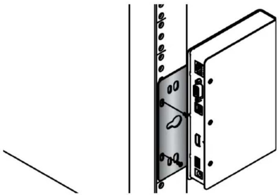
natural_image
Diagram of a server rack with attached door and socket, showing internal components (no text or symbols)Wall Mounting
Non-Slim Transmitters
Note: Steps for the non-slim transmitters (KE6900, KE6900A, KE6910, KE6912, KE6920, KE6922, KE6940, KE6940A, KE8950, KE8952, KE9950, and KE9952) are the same and KE6900 will be shown in the steps below.
Use the center hole to screw the bracket to a secure wall surface.
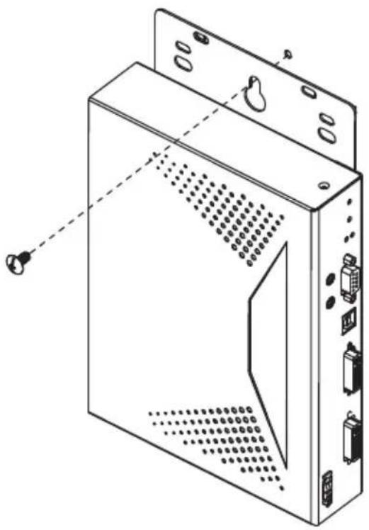
natural_image
Line drawing of a computer tower case with ventilation slots and ports (no text or symbols)Slim Transmitters - KE6900ST
Use the center hole to screw the bracket to a secure wall surface.
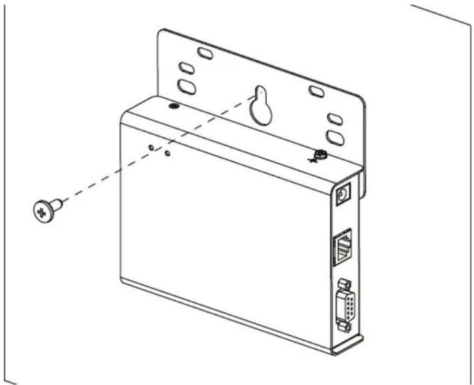
natural_image
Technical line drawing of a device rear panel with labeled ports and connectors (no text or symbols)Slim Transmitters - KE8900ST / KE9900ST
Use the mounting bracket's center screw hole to mount the unit on a wall.
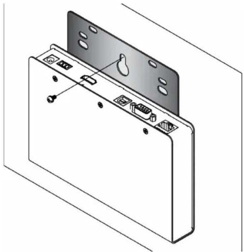
natural_image
Technical line drawing of a device rear panel with ports and connectors (no text or symbols)KE6900 / KE6940 Point-to-Point Installation
Setting up the KE6900 / KE6940 system in a point-to-point configuration is simply a matter of plugging in the cables.
Note: In a point-to-point configuration, no administrator setup is necessary.
Make sure that all the equipment is powered off. Refer to the installation diagrams on the next two pages and do the following:
- On the Transmitter side, plug the mouse, keyboard, DVI monitor, microphone and speakers into the ports on the Console section of the KE6900T / KE6940T. Each port is marked with an appropriate icon to indicate itself.*
- Connect the USB KVM cable provided to the KVM Ports on the front of the KE6900T / KE6940T.
- Connect the other end of the USB KVM cable to the keyboard, video, mouse, speaker and microphone ports on the computer.
- For control of serial devices, connect the RS-232 serial port on the Transmitter to a serial port on the computer.
- Connect a Cat 5e/6 cable to the KE6900T / KE6940T's LAN port.
- Plug the power adapter into an AC source; and plug the other end into the KE6900T / KE6940T's Power Jack.
- On the Receiver side, plug the mouse, keyboard, DVI monitor, microphone, and speakers into the ports on the Console section of the KE6900R / KE6940R.**
- Connect the other end of the Cat 5e/6 cable to the KE6900R / KE6940R's LAN port.
- Plug the second power adapter into an AC source; and plug the other end into the KE6900R / KE6940R's Power Jack.
- Power on the computer.
Note: 1. If installing the KE6940 with two DVI monitors, connect the second DVI monitor via a DVI cable into the additional ports on the KE6940 and computer.
- A keyboard or mouse with special functions may need to use the USB ports for advanced features to work (see USB Mode, page 203).
KE6900 / KE6940 Point-to-Point Installation 1 of 2
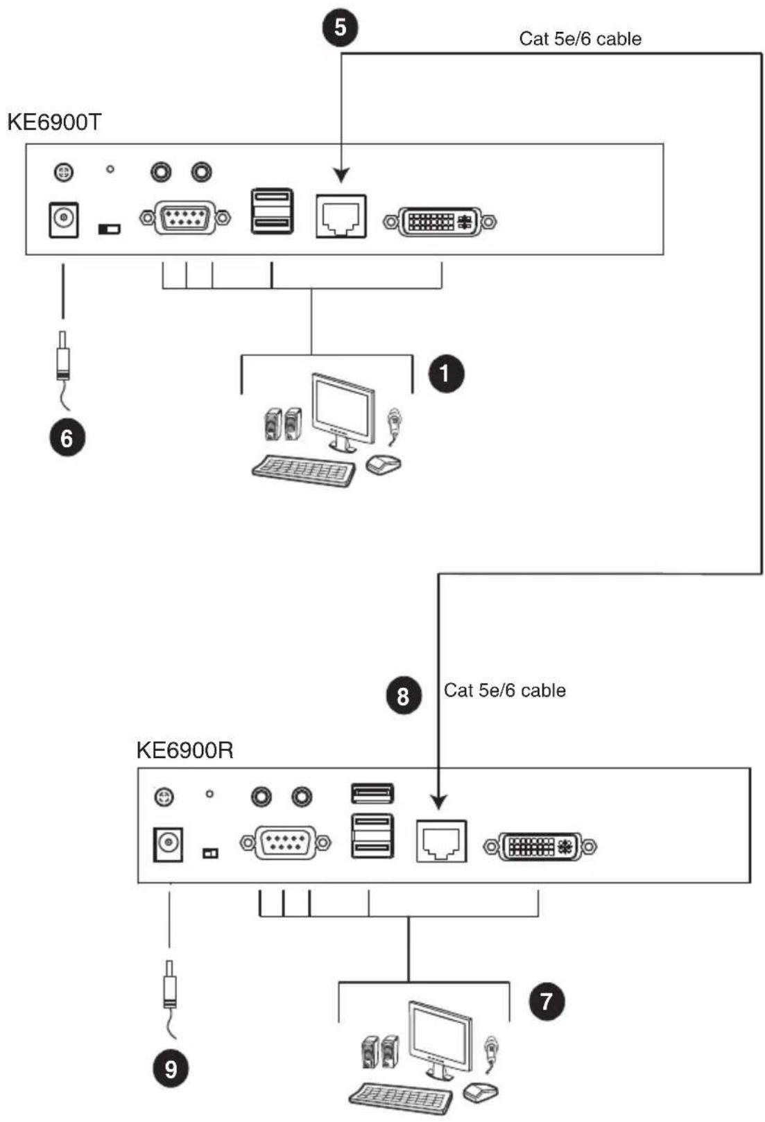
flowchart
graph TD
    A["KE6900T"] --> B["Cat 5e/6 cable"]
    A --> C["1"]
    C --> D["KE6900R"]
    D --> E["Cat 5e/6 cable"]
    D --> F["7"]
    D --> G["9"]
    D --> H["8"]
Note: The diagram above shows the KE6900T and KE6900R. The KE6940 installation is the same except that an additional DVI monitor can be connected at each end for a dual-view display setup.
KE6900 / KE6940 Point-to-Point Installation 2 of 2
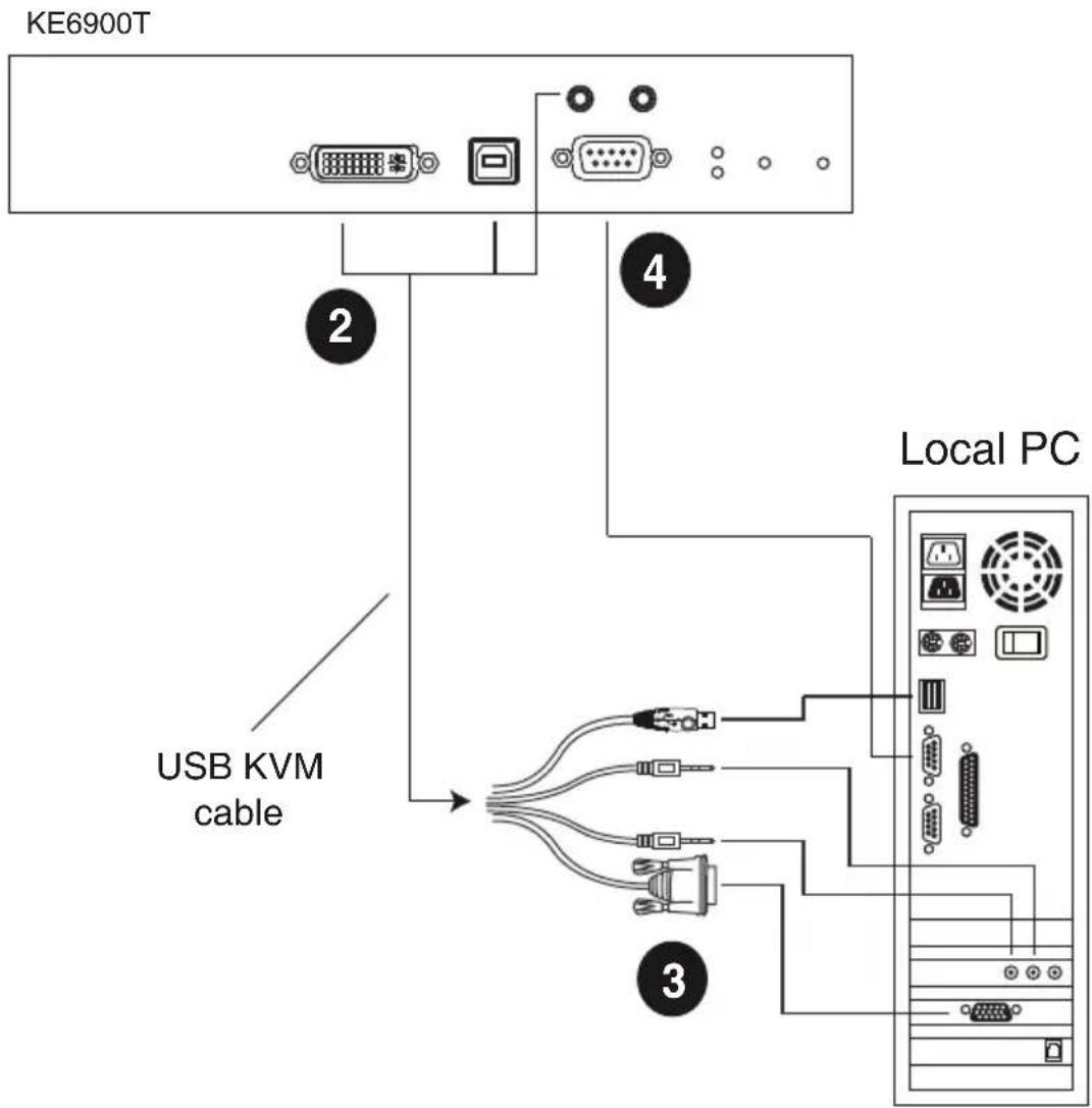
Note: The serial port on the Transmitter (shown above) connects to the computer; the serial port on the Receiver (not shown) connects to a serial device (optional).
KE6900A / KE6940A Point-to-Point Installation
Setting up the KE6900A / KE6940A system in a point-to-point configuration is simply a matter of plugging in the cables.
Note: In a point-to-point configuration, no administrator setup is necessary.
Make sure that all the equipment is powered off. Refer to the installation diagrams on the next two pages and do the following:
- (Optional) Connect a grounding wire between the extender's grounding terminal and a suitable grounded object.
- On the transmitter side, plug the mouse, keyboard, DVI monitor, and serial devices into the ports on the Console section of the transmitter (KE6900AT/KE6940AT) ^1 .
- Connect the DVI-D cable and the USB 2.0 Type-A to Type-B cable provided with this package into the KVM Ports on the front of the transmitter.
- Connect the other end of the USB DVI-D KVM cable into the keyboard, video, mouse, speaker and microphone ports on the computer.
- For control of serial devices, connect the RS-232 port on the front of the transmitter to a serial port on the computer.
- Connect a Cat 5e/6 cable to the transmitter's LAN port.
- Plug the mouse, keyboard, DVI monitor, and serial devices into the ports on the Console section of the receiver (KE6900AR/KE6940AR) ^2 .
- Connect the other end of the Cat 5e/6 cable to the receiver's LAN port.
- Instead of connecting through the LAN ports, you can choose to connect the extenders through the SFP slots. To do so, plug SFP modules into the transmitter and receiver's SFP slots, then connect each end of Gigabit Ethernet (GbE) optical fiber between the SFP modules ^3 .
- Plug the power adapters into AC sources with the power cords and plug the other ends into the transmitter and receiver's power jacks respectively.
- (Optional) For power redundancy, plug the second power adapters into AC sources with the power cords and plug the other ends into the transmitter and receiver's power jacks.
- Power on the computer.
Note: 1. If installing the KE6940A with two DVI monitors, connect the second DVI monitor via a DVI cable into the additional ports on the KE6940 and computer.
2. A keyboard or mouse with special functions may need to use the USB ports for advanced features to work (see USB Mode, page 203).
3. The SFP module 2A-136G / 2A-137G is sold separately. Contact your ATEN dealer for product information.
KE6900A / KE6940A Point-to-Point Installation 1 of 2
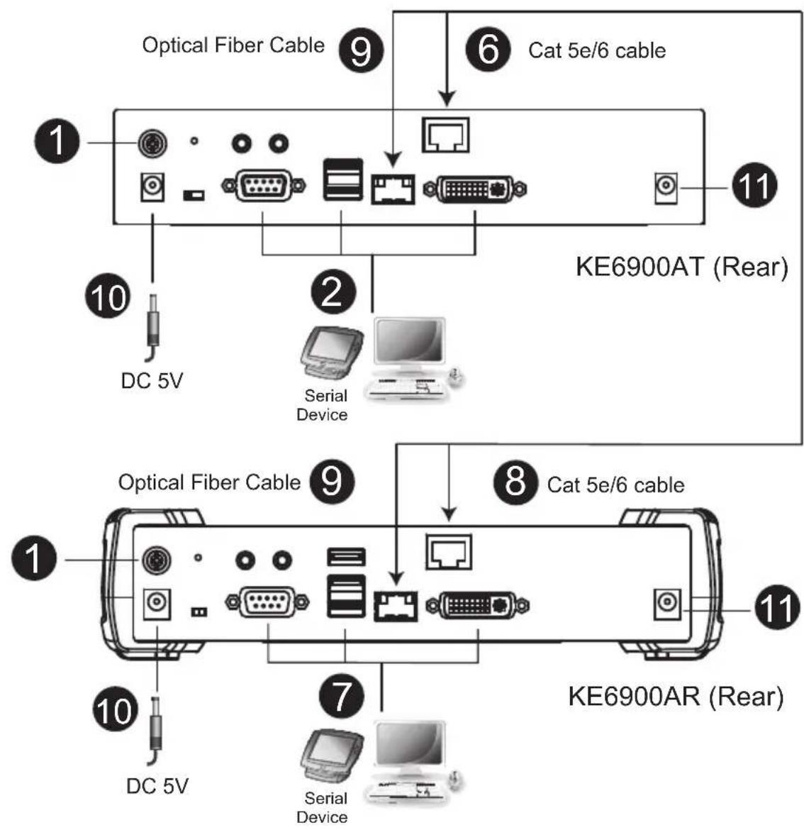
flowchart
graph TD
    A["KE6900AT (Rear)"] --> B["Optical Fiber Cable"]
    A --> C["Cat 5e/6 cable"]
    B --> D["DC 5V"]
    C --> E["Serial Device"]
    D --> F["10"]
    E --> G["2"]
    F --> H["11"]
    G --> I["7"]
    H --> J["10"]
    I --> K["10"]
    J --> L["10"]
    K --> M["10"]
    L --> N["10"]
    M --> O["10"]
    N --> P["10"]
    O --> Q["10"]
    P --> R["10"]
    Q --> S["10"]
    R --> T["10"]
    S --> U["10"]
    T --> V["10"]
    U --> W["10"]
    V --> X["10"]
    W --> Y["10"]
    X --> Z["10"]
    Y --> AA["10"]
Note: The diagram above shows the KE6900AT and KE6900AR. The KE6940A installation is the same except that an additional DVI monitor can be connected at each end for a dual-view display setup.
KE6900A / KE6940A Point-to-Point Installation 2 of 2
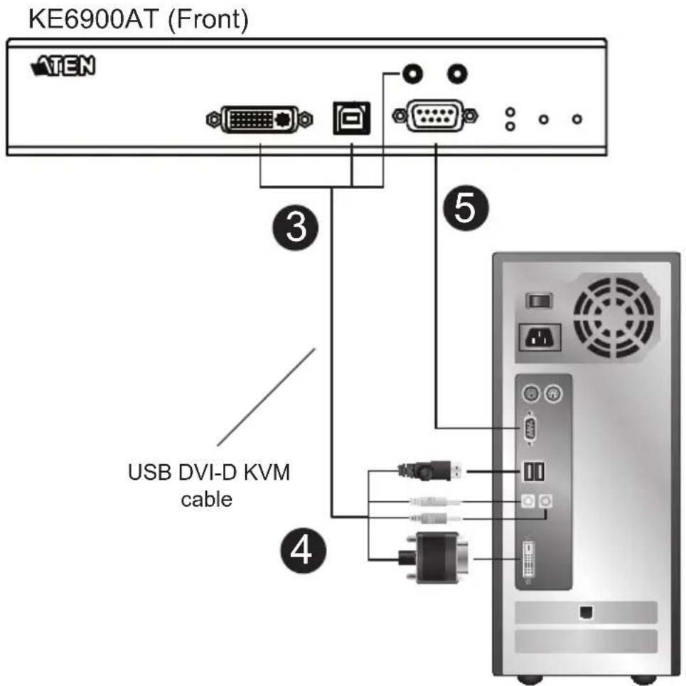
Note: The serial port on the Transmitter (shown above) connects to the computer; the serial port on the Receiver (not shown) connects to a serial device (optional).
KE6910 / KE6912 Point-to-Point Installation
Setting up the KE6910 / KE6912 system in a point-to-point configuration is simply a matter of plugging in the cables.
Note: In a point-to-point configuration, no administrator setup is necessary.
Make sure that all the equipment is powered off. Refer to the installation diagrams on the next two pages and do the following:
- (Optional) Use the grounding wire to connect the extender's grounding terminal to a suitable grounded object.
- On the transmitter side, plug the mouse, keyboard, DVI-D monitor, serial devices, microphone and speakers into the ports on the Console section of the KE6910T / KE6912T.
- Connect the USB DVI-D KVM cable provided with this package into the KVM Ports and the audio ports on the front of the KE6910T / KE6912T.
- Connect the other end of the USB DVI-D KVM cable into the keyboard, video, mouse, speaker and microphone ports on the computer.
- For control of serial devices, connect the RS-232 port on the front of the transmitter to a serial port on the computer.
- Connect a Cat 5e/6 cable to the KE6910T / KE6912T's LAN port.
- On the receiver side, plug the mouse, keyboard, DVI-D monitor, serial devices, microphone, and speakers into the ports on the Console section of the KE6910R / KE6912R.
- Connect the other end of the Cat 5e/6 cable to the KE6910R / KE6912R's LAN port.
- Instead of connecting through the LAN ports, you can choose to connect the KE6910 / KE6912 through the SFP slots. To do so, plug SFP modules into the transmitter and receiver's SFP slots, then connect each end of Gigabit Ethernet (GbE) optical fiber between the SFP modules.*
-
Plug the power adapters into AC sources with the power cords; then plug the other ends into the transmitter and receiver's power jacks respectively. The KE6912 supports Power over Ethernet (PoE), thus the power can be supplied through PoE network switch, without the need of a power adapter.
-
(Optional) For power redundancy, plug the second power adapters into AC sources with the power cords; then plug the other ends into the transmitter and receiver's power jacks.**
- Power on the computer.
Note: 1. The SFP module 2A-136G/2A-137G is sold separately. Contact your ATEN dealer for product information.
- Available for KE6910T and KE6910R only. The second power adapter with the power cord is sold separately. Contact your ATEN dealer for product information. Power redundancy forKE6912T and KE6912R can be achieved with the PoE function.
KE6910 / KE6912 Point-to-Point Installation 1 of 2
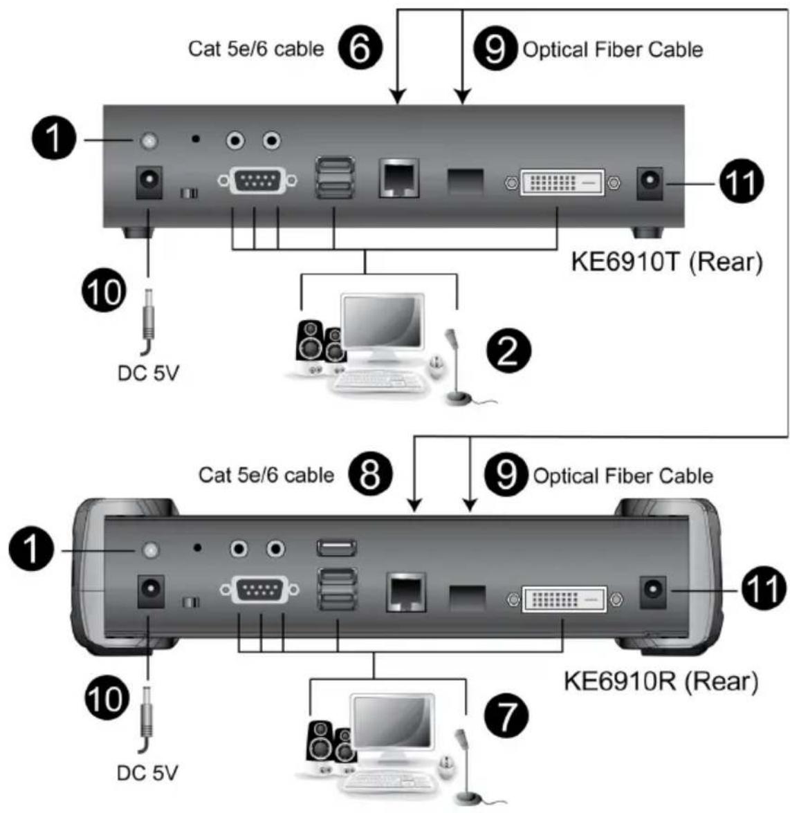
KE6910 / KE6912 Point-to-Point Installation 2 of 2
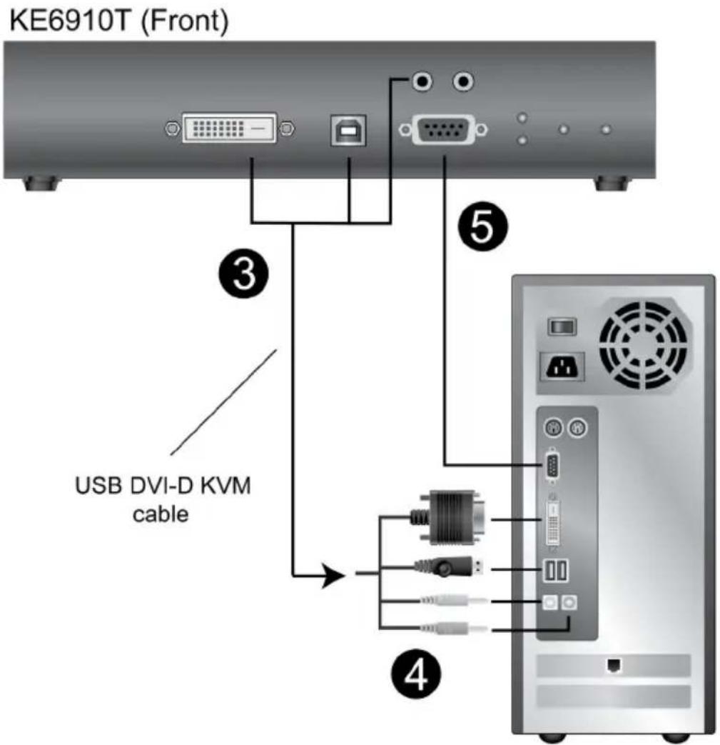
KE6920 / KE6922 Point-to-Point Installation
Setting up the KE6920 / KE6922 system in a point-to-point configuration is simply a matter of plugging in the cables.
Note: In a point-to-point configuration, no administrator setup is necessary.
Make sure that all the equipment is powered off. Refer to the installation diagrams on the next two pages and do the following:
- (Optional) Connect a grounding wire between the extender's grounding terminal and a suitable grounded object.
- On the transmitter side, plug the mouse, keyboard, DVI monitor, and serial devices into the ports on the Console section of the transmitter (KE6920T/KE6922T).
- Connect the DVI-D cable and the USB 2.0 Type-A to Type-B cable provided with this package into the KVM Ports on the front of the transmitter.
- Connect the other end of the USB DVI-D KVM cable into the keyboard, video, mouse, speaker and microphone ports on the computer.
- For control of serial devices, connect the RS-232 port on the front of the transmitter to a serial port on the computer.
- Connect a Cat 5e/6 cable to the transmitter's LAN port.
- Plug the mouse, keyboard, DVI monitor, and serial devices into the ports on the Console section of the receiver (KE6920R/KE6922R).
- Connect the other end of the Cat 5e/6 cable to the receiver's LAN port.
- Instead of connecting through the LAN ports, you can choose to connect the extenders through the SFP slots. To do so, plug SFP modules into the transmitter and receiver's SFP slots, then connect each end of Gigabit Ethernet (GbE) optical fiber between the SFP modules ^1 .
- Plug the power adapters into AC sources with the power cords and plug the other ends into the transmitter and receiver's power jacks respectively.
- (Optional) For power redundancy, plug the second power adapters into AC sources with the power cords and plug the other ends into the transmitter and receiver's power jacks ^2 .
- Power on the computer.
Note: 1. The SFP module 2A-136G / 2A-137G is sold separately. Contact your ATEN dealer for product information.
- Available for KE6920T and KE6920R only. The second power adapter with the power cord is sold separately. Contact your ATEN dealer for product information. Power redundancy forKE6922T and KE6922R can be achieved with the PoE function.
KE6920 / KE6922 Point-to-Point Installation 1 of 2
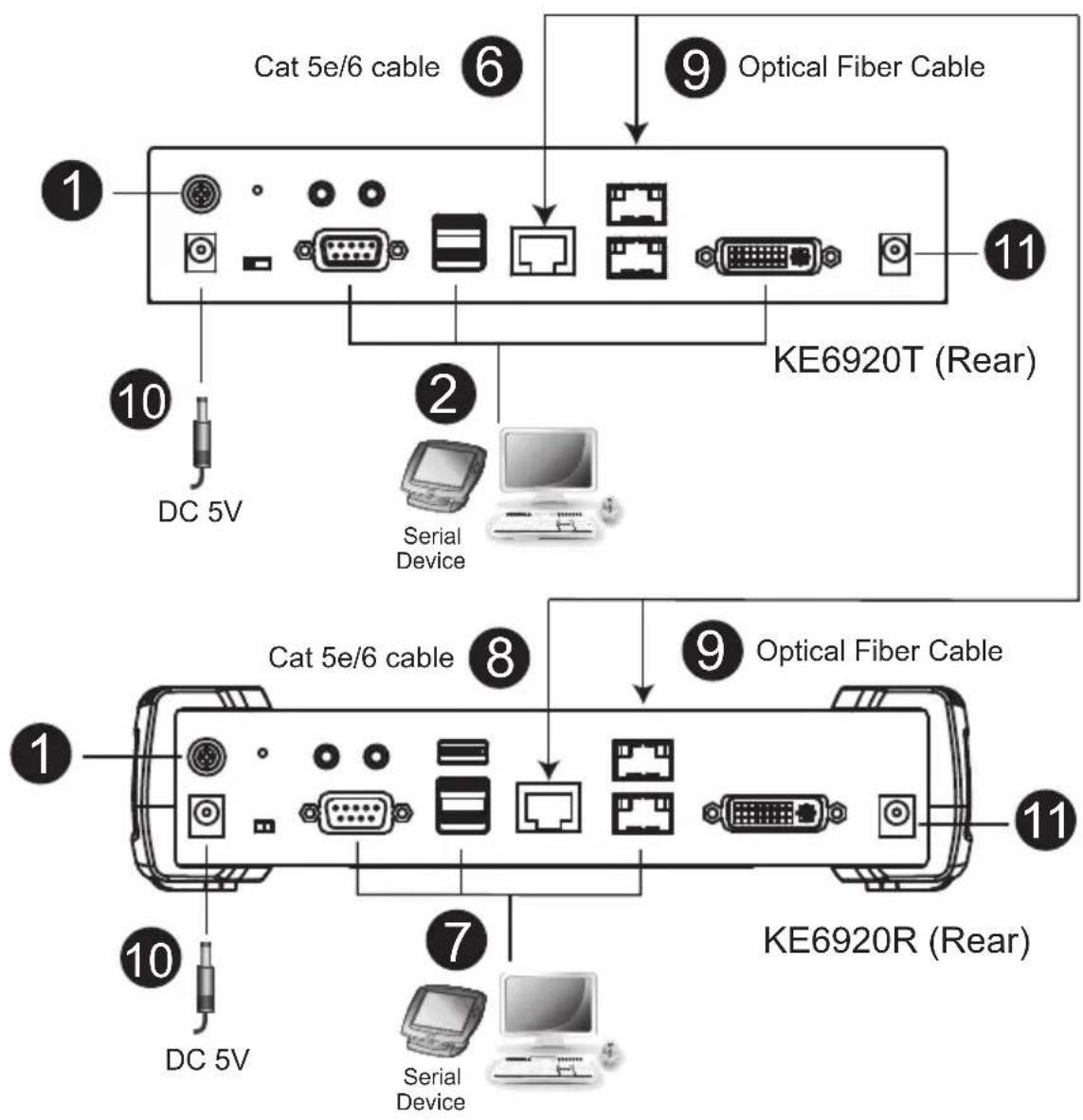
KE6920 / KE6922 Point-to-Point Installation 2 of 2
KE6920T (Front)
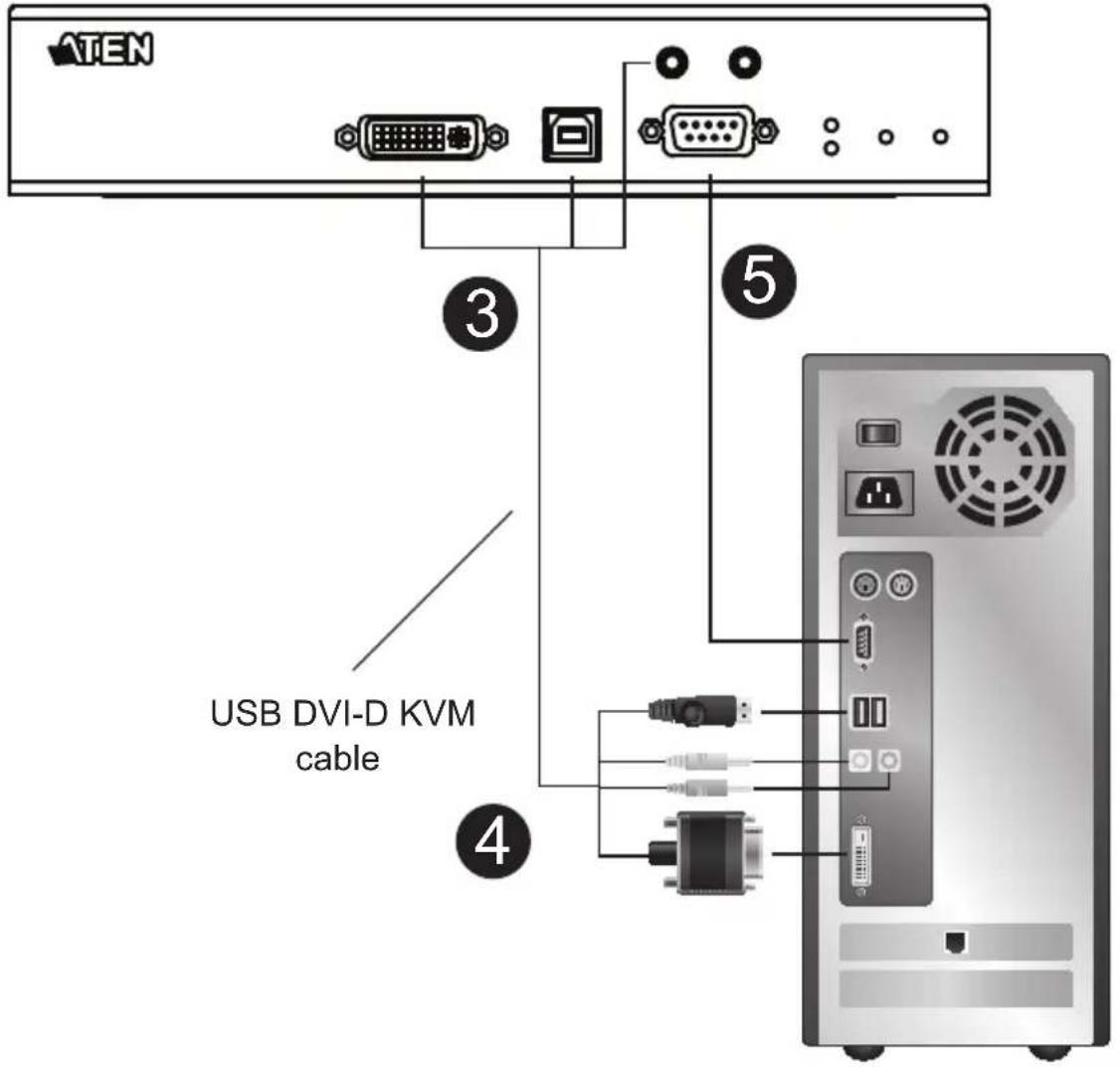
KE8950 / KE8952 Point-to-Point Installation
Setting up the KE8950 / KE8952 system in a point-to-point configuration is simply a matter of plugging in the cables.
Note: In a point-to-point configuration, no administrator setup is necessary.
Make sure that all the equipment is powered off. Refer to the installation diagrams on the next two pages and do the following:
- On the transmitter side, plug the mouse, keyboard, HDMI monitor, microphone and speakers into the ports on the Console section of the KE8950T / KE8952T. Each port is marked with an appropriate icon to indicate its function.
- Connect the USB HDMI KVM cable provided with this package into the KVM Ports on the front of the KE8950T / KE8952T.
- Connect the other end of the USB HDMI KVM cable into the keyboard, video, mouse, speaker and microphone ports on the computer.
- For control of serial devices, connect the RS-232 serial port on the transmitter to a serial port on the computer.
- Connect a Cat 5e/6 cable to the KE8950T / KE8952T's LAN port, or a Gigabit Ethernet (GbE) optical fiber cable to the SFP port.
- Plug the power adapter into an AC source; then plug the other end into the KE8950T / KE8952T's power jack.*
- On the receiver side, plug the mouse, keyboard, HDMI monitor, microphone, and speakers into the ports on the Console section of the KE8950R / KE8952R.
- Connect the other end of the Cat 5e/6 cable to the KE8950R / KE8952R's LAN port; or the other end of the Gigabit Ethernet (GbE) optical fiber cable to the SFP port.
- Plug the second power adapter into an AC source; then plug the other end into the KE8950R / KE8952R's power jack.*
- Power on the computer.
Note: Power adapters are not provided with KE8952 units. Please contact your ATEN dealer to purchase additional power adapters.
KE8950 / KE8952 Point-to-Point Installation 1 of 2
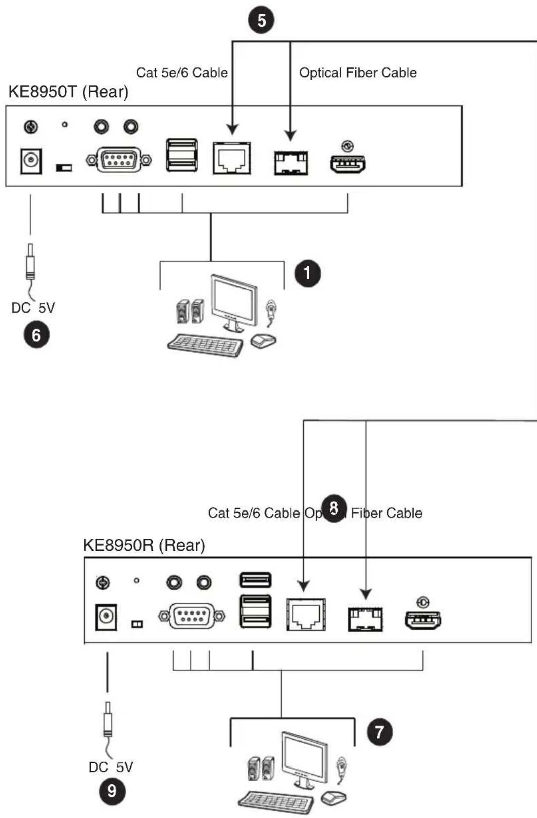
flowchart
graph TD
    A["KE8950T (Rear)"] --> B["Cat 5e/6 Cable"]
    A --> C["Optical Fiber Cable"]
    D["KE8950R (Rear)"] --> E["Cat 5e/6 Cable Opt Fiber Cable"]
    D --> F["DC 5V"]
    D --> G["DC 5V"]
    D --> H["Computer"]
Note: Power adapters are not provided with the KE8952. Please contact your ATEN dealer to purchase additional power adapters, or use the Power over Ethernet (PoE) feature to supply power to the KE8952.
KE8950 / KE8952 Point-to-Point Installation 2 of 2
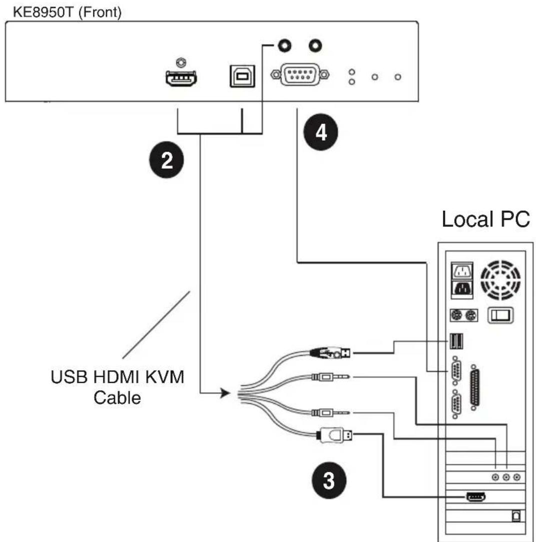
flowchart
graph TD
    A["KE8950T (Front)"] --> B["2"]
    A --> C["4"]
    B --> D["USB HDMI KVM Cable"]
    C --> E["Local PC"]
    D --> F["3"]
    E --> F
    style A fill:#f9f,stroke:#333
    style B fill:#ccf,stroke:#333
    style C fill:#ccf,stroke:#333
    style D fill:#cfc,stroke:#333
    style E fill:#cfc,stroke:#333
Note: The serial port on the Transmitter (shown above) connects to the computer; the serial port on the Receiver (not shown) connects to a serial device (optional).
KE6900ST Point-to-Point Installation
The KE6900ST DVI KVM over IP Extender Lite is a cost saving alternative for installations with Transmitters that don't need a local console or audio transmission but want the connectivity features of advanced KE models.
Setting up the KE6900ST system in a point-to-point configuration is simply a matter of plugging in the cables. Make sure that all the equipment is powered off. Refer to the installation diagrams on the next page and do the following:
- Connect the USB DVI-D KVM Cable (provided with this package) to the USB and DVI-D ports on the front of the KE6900ST.
- Connect the other end of the USB DVI-D KVM Cable to USB and DVI video ports on the computer.
- For control of serial devices, connect the RS-232 serial port on the KE6900ST to a serial port on the computer.
- Plug the power adapter (provided with this package) into an AC source; and plug the other end into the KE6900ST Power Jack.
- Connect a Cat 5e/6 cable to the KE6900ST's LAN port.
- Connect the other end of the Cat 5e/6 cable to the KE69x0R's* LAN port.
- On the Receiver side, plug the mouse, keyboard and DVI monitor into the ports on the Console section of the KE69x0R.*
- Plug the second power adapter into an AC source; and plug the other end into the KE69x0R's Power Jack.
- Power on the computer.
Note: KE69x0R units are required and sold separately.
Setting up a LAN Installation
Setting up the KE6900ST on a network allows point-to-point, point-to-multipoint, and multipoint-to-multipoint computer to console operation by connecting multiple KE69x0 devices on the same TCP/IP LAN. To setup a LAN installation, simply connect the Cat 5e/6 cable (in step 5 above) to the network instead of directly between two KE69x0 devices and see KE6900 / KE6940 LAN Installation, page 103 for details.
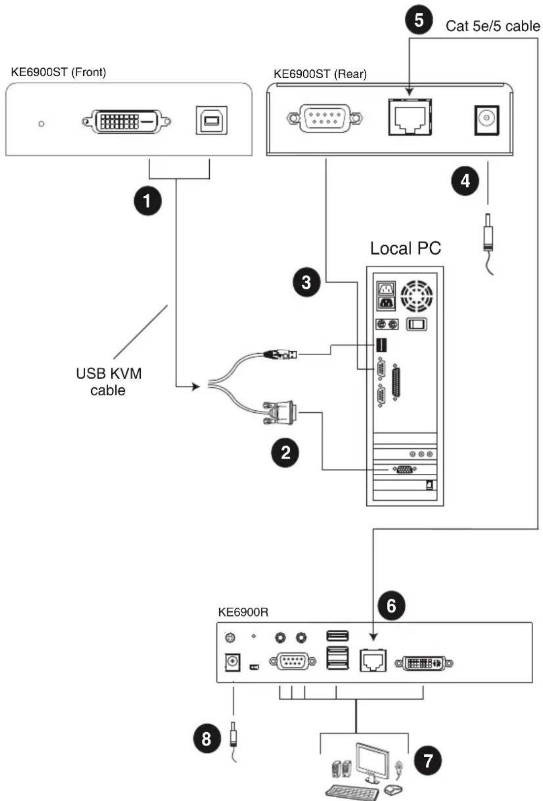
flowchart
graph TD
    A["KE6900ST (Front)"] -->|USB KVM cable| B["Local PC"]
    C["KE6900ST (Rear)"] -->|Cat 5e/5 cable| D["Local PC"]
    B --> E["KE6900R"]
    E --> F["Computer"]
    style A fill:#f9f,stroke:#333
    style C fill:#f9f,stroke:#333
    style E fill:#ccf,stroke:#333
    style F fill:#ccf,stroke:#333
KE8900S Point-to-Point Installation
The KE8900S Slim HDMI KVM over IP Extender is a cost saving alternative for installations that don't need a local console or audio transmission but want the connectivity features of advanced KE models.
Setting up the KE8900S system in a point-to-point configuration is simply a matter of plugging in the cables. Make sure that all the equipment is powered off. Refer to the installation diagrams on the next page and do the following:
- (Optional) Connect the grounding terminals of KE8900ST and KE8900SR to a suitable grounded object using grounding wires.
- Connect the USB HDMI KVM Cable provided with this package between a computer and the KE8900ST. Please use the USB Type-B end of the USB HDMI KVM Cable for the KE8900ST as it has a USB Type-B port.
- Connect a Cat 5e/6 cable between the LAN ports of KE8900ST and KE8900SR.
- Connect a USB mouse/keyboard to the front panel of the KE8900SR and HDMI monitor to the rear panel of the KE8900SR.
- Plug the power adapters into power sockets; then plug the other ends respectively into KE8900ST and KE8900SR's power jacks. For KE8900ST, you can choose to use the terminal block for power input. Insert DC + and - wires (DC 12 to 48V) to the terminal block according to the icon.*
- (Optional) For control of serial devices, connect the RS-232 serial port on the KE8900ST to a serial port on the computer.
- Power on the computer.
Setting up a LAN Installation
Setting up the units on a network allows point-to-point, point-to-multipoint, and multipoint-to-multipoint computer to console operation by connecting multiple KE Series devices on the same TCP/IP LAN. To set up a LAN installation, simply connect the Cat 5e/6 cable (in step 3) to the network instead of directly between two KE Series devices. As an example, please refer to KE6900 / KE6940 LAN Installation.
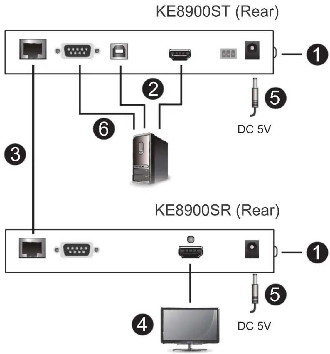
KE8900SR (Front)
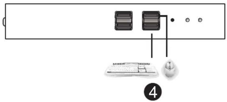
KE9900ST Point-to-Point Installation
The KE9900ST DisplayPort KVM over IP Extender Lite is a cost saving alternative for installations with Transmitters that don't need a local console or audio transmission but want the connectivity features of advanced KE models.
Setting up the KE9900ST system in a point-to-point configuration is simply a matter of plugging in the cables. Make sure that all the equipment is powered off. Refer to the installation diagrams on the next page and do the following:
- (Optional) Connect the grounding terminal of the KE9900ST to a suitable grounded object using a grounding wire.
- Connect the supplied DisplayPort Cable between the DisplayPort ports of the computer and the KE9900ST.
- With the supplied USB 2.0 Type-A to Type-B cable, connect the USB Type-A end to the computer and the Type-B end to the KE9900ST.
- (Optional) For control of serial devices, connect the RS-232 serial port on the KE9900ST to a serial port on the computer.
- Connect a Cat 5e/6 cable between the LAN ports of KE9900ST and the receiver unit* (e.g. KE8900SR).
- Connect a USB mouse/keyboard and HDMI monitor to their respective ports on the KE8900SR.
- Power the KE8900SR (e.g. plugging power adapter between the unit and a power socket).
- Plug the power adapter into a power socket; then plug the other end into KE9900ST's power jack. Alternatively, you can choose to use the terminal block for power input. Insert DC + and - wires (DC 12 to 48V) to the terminal block according to the icon.
- Power on the computer.
Note: A KE Series receiver unit is required and sold separately.
Setting up a LAN Installation
Setting up the units on a network allows point-to-point, point-to-multipoint, and multipoint-to-multipoint computer to console operation by connecting multiple KE Series devices on the same TCP/IP LAN. To set up a LAN installation, simply connect the Cat 5e/6 cable (in step 5) to the network instead
of directly between two KE Series devices. As an example, please refer to KE6900 / KE6940 LAN Installation.
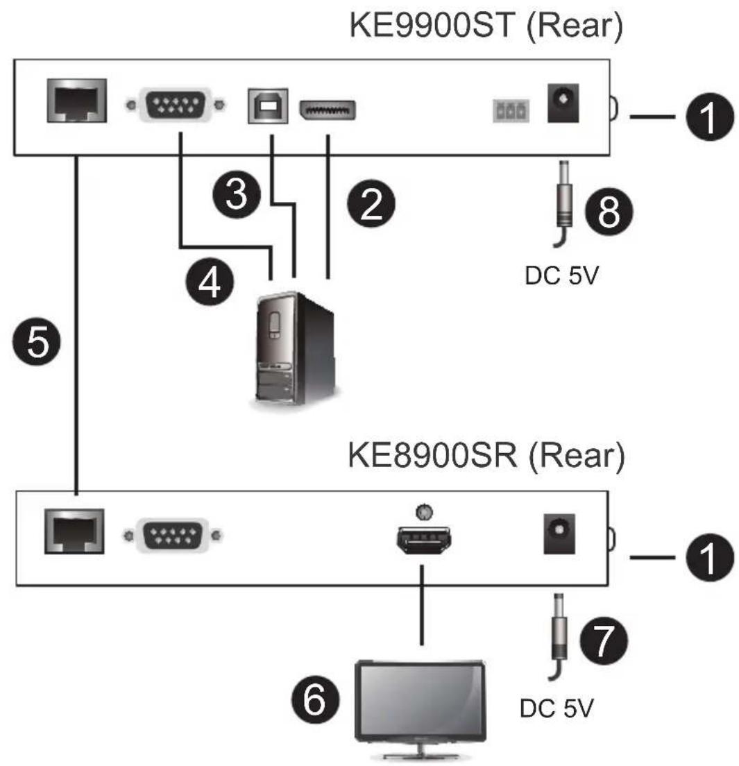
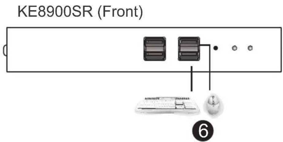
KE9950 / KE9952 Point-to-Point Installation
Setting up the KE9950 / KE9952 system in a point-to-point configuration is simply a matter of plugging in the cables.
Note: In a point-to-point configuration, no administrator setup is necessary.
Make sure that all the equipment is powered off. Refer to the installation diagrams on the next two pages and do the following:
- (Optional) Connect the extender's grounding terminal to a suitable grounded object using the grounding wire.
- On the transmitter side, plug the mouse, keyboard, DisplayPort monitor, serial devices, microphone and speakers into the ports on the Console section of the KE9950T / KE9952T.
- Connect the DisplayPort cable, the USB 2.0 Type-A to Type-B cable provided with this package and the audio ports into the KVM Ports on the front of the KE9950T / KE9952T.
- Connect the other end of the DisplayPort cable and the USB 2.0 Type-A to Type-B and audio cables into the keyboard, video, mouse, speaker and microphone ports on the computer.
- For control of serial devices, connect the RS-232 port on the front of the transmitter to a serial port on the computer.
- Connect a Cat 5e/6 cable to the KE9950T / KE9952T's LAN port.
- On the receiver side, plug the mouse, keyboard, DisplayPort monitor, serial devices, microphone and speakers into the ports on the Console section of the KE9950R / KE9952R.
- Connect the other end of the Cat 5e/6 cable to the KE9950R / KE9952R's LAN port.
- Instead of connecting through the LAN ports, you can choose to connect the KE9950 / KE9952 through the SFP slots. To do so, plug SFP modules into the transmitter and receiver's SFP slots, then connect each end of Gigabit Ethernet (GbE) optical fiber between the SFP modules.*
-
Plug the power adapters into AC sources with the power cords and plug the other ends into the transmitter and receiver's power jacks respectively. The KE9952 supports Power over Ethernet (PoE) where power can be supplied through a PoE network switch instead of using a power adapter.
-
(Optional) For power redundancy, plug the second power adapters into AC sources with the power cords and plug the other ends into the transmitter and receiver's second power jacks.**
- Power on the computer.
Note: 1. The SFP module 2A-136G / 2A-137G is sold separately. Contact your ATEN dealer for product information.
- Available for KE9950T and KE9950R only. The second power adapter with the power cord is sold separately. Contact your ATEN dealer for product information. Power redundancy for KE9952T and KE9952R can be achieved with the PoE function.
KE9950 / KE9952 Point-to-Point Installation 1 of 2
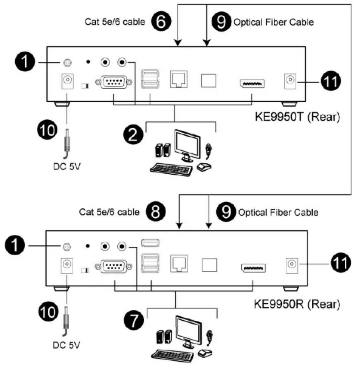
flowchart
graph TD
    A["KE9950T (Rear)"] --> B["Cat 5e/6 cable"]
    A --> C["Optical Fiber Cable"]
    B --> D["1"]
    B --> E["2"]
    B --> F["3"]
    C --> G["4"]
    C --> H["5"]
    D --> I["DC 5V"]
    E --> J["DC 5V"]
    F --> K["DC 5V"]
    G --> L["7"]
    H --> M["8"]
    I --> N["10"]
    J --> O["10"]
    K --> P["10"]
    L --> Q["10"]
    M --> R["10"]
    N --> S["10"]
    O --> T["10"]
    P --> U["10"]
    Q --> V["10"]
    R --> W["10"]
    S --> X["10"]
    T --> Y["10"]
    U --> Z["10"]
    V --> AA["10"]
    W --> AB["10"]
    X --> AC["10"]
    Y --> AD["10"]
Note: Power adapters are not provided with the KE9952. Please contact your ATEN dealer to purchase additional power adapters, or use the Power over Ethernet (PoE) feature to supply power to the KE9952.
KE9950 / KE9952 Point-to-Point Installation 2 of 2
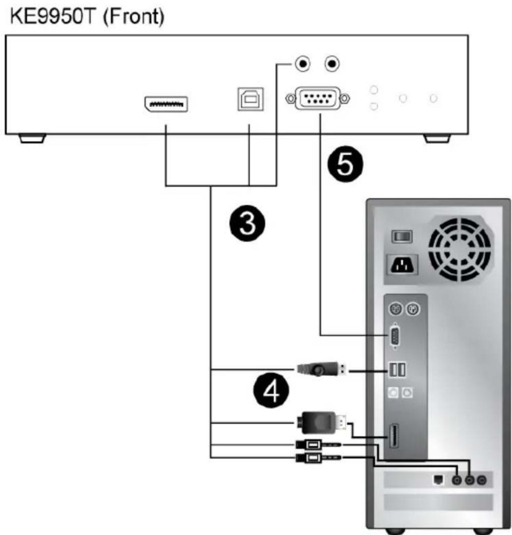
Note: The serial port on the Transmitter (shown above) connects to the computer; the serial port on the Receiver (not shown) connects to a serial device (optional).
KE6900 / KE6940 LAN Installation
Setting up the units on a network allows point-to-point, point-to-multipoint, and multipoint-to-multipoint computer to console operation by connecting multiple KE6900 / KE6900ST / KE6940 devices on the same TCP/IP LAN. Prior to setup we recommended laying out the plans for your KE installation using our performance guide (see Keys to Network Performance, page 339).
Note: 1. The units are preconfigured with factory-default network settings. If you install only one set of KE Series units, you do not need to change these default network settings. See Default IP Addresses, page 126, for further details.
2. In a network setup with multiple units, each Transmitter and Receiver must be configured with a unique IP address. See Network Configuration, page 125, for further details.
3. We recommended using 1000Mbps Gigabit Ethernet switches (wire speeds, non-blocking with 1Gbps/1.5Mpps performance per port) between KE Series devices installed on different LAN segments. 10/100Mbps switches might cause poor performance.
4. In multipoint configurations, the IGMP and flow control function of your network switches/hubs must be enabled to avoid the deterioration of data throughput. To ensure functionality use a layer 3 switch that supports IGMP queries.
5. If your network uses cascaded switches, please check to ensure the data throughput is sufficient.
6. To get the best performance, we suggest creating a private network for KE devices, as they are bandwidth-intensive devices.
Make sure that all the equipment is powered off. Refer to the installation diagram on the following page, and do the following:
- On the Transmitter side, plug the mouse, keyboard, DVI monitor, microphone and speakers into the ports on the Console section of the KE6900T / KE6940T.* Each port is marked with an appropriate icon to indicate itself.
- Connect the USB KVM cable provided to the KVM Ports on the front of the KE6900T / KE6940T.
-
Connect the other end of the USB KVM cable to the keyboard, video, mouse, speaker and microphone ports on the computer.
-
For control of serial devices, connect the RS-232 serial port on the Transmitter to a serial port on the computer.
- Use a Cat 5e/6 cable to connect the KE6900T / KE6940T's LAN port to the local area TCP/IP network.
- Plug the power adapter into an AC source; and plug the other end into the KE6900T / KE6940T's Power Jack.
- On the Receiver side, plug the mouse, keyboard, DVI monitor, microphone, and speakers into the ports on the Console section of the KE6900R / KE6940R.**
- Use a Cat 5e/6 cable to connect the KE6900R / KE6940R's LAN port to the local area TCP/IP network.
- Plug the second power adapter into an AC source; and plug the other end into the KE6900R / KE6940R's Power Jack.
- Use the OSD on the Receiver to configure the network settings for both devices (See Network Configuration, page 125).
- Repeat these steps for each Transmitter and Receiver you wish to install on the network.
- Power on the computer(s).
Note: 1. If installing the KE6940 with two DVI monitors, connect the second DVI monitor via a DVI cable into the additional ports on the KE6940 and computer.
- A keyboard or mouse with special functions may need to use the USB ports for advanced features to work (see USB Mode, page 203).
KE6900 / KE6940 Network Installation Diagram 1 of 2
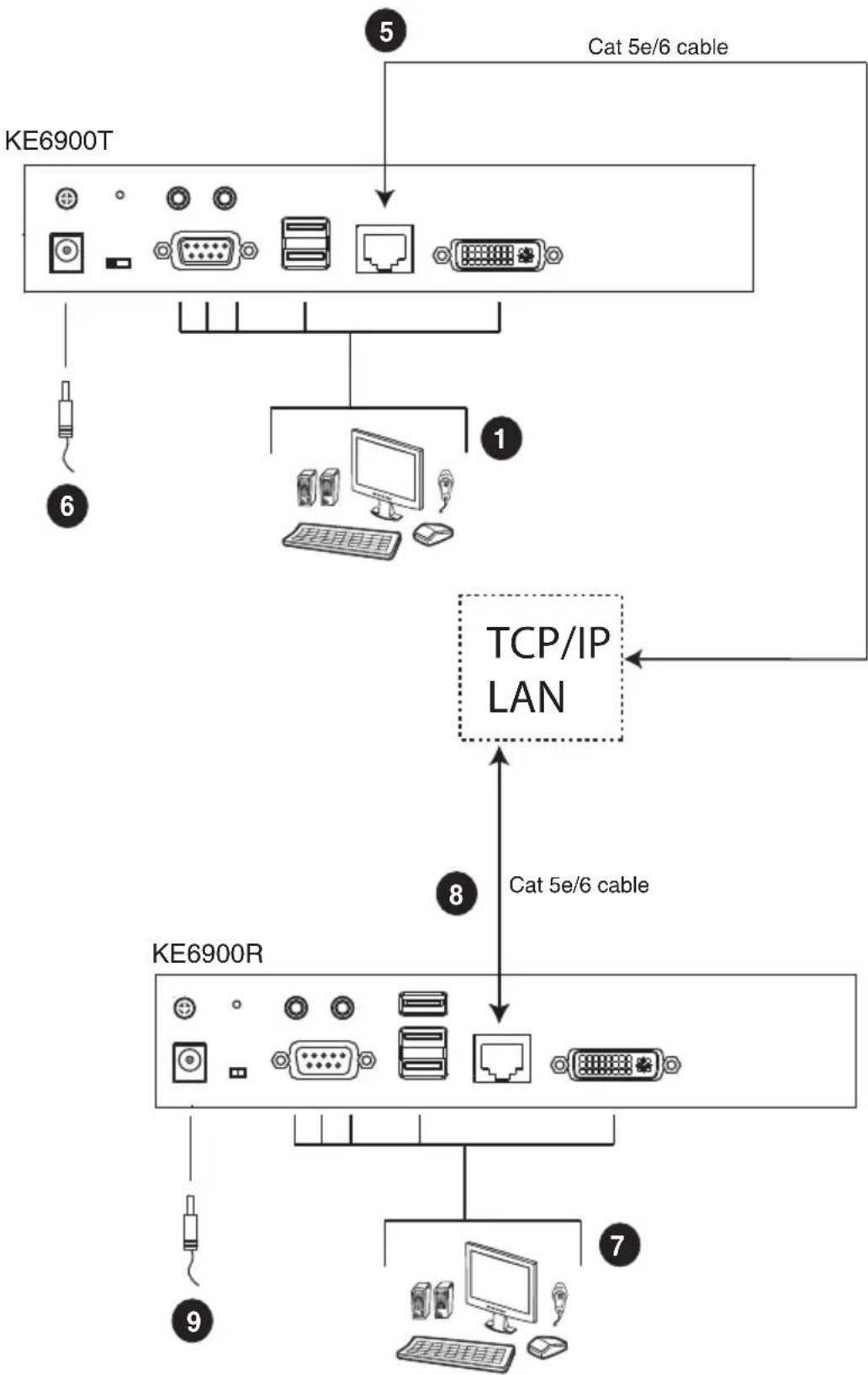
flowchart
graph TD
    A["KE6900T"] -->|Cat 5e/6 cable| B["1"]
    A --> C["KE6900R"]
    C -->|Cat 5e/6 cable| D["TCP/IP LAN"]
    D --> E["7"]
    D --> F["8"]
    F --> G["9"]
    style A fill:#f9f,stroke:#333
    style B fill:#ccf,stroke:#333
    style C fill:#cfc,stroke:#333
    style D fill:#fcc,stroke:#333
    style E fill:#ffc,stroke:#333
    style F fill:#fcc,stroke:#333
    style G fill:#ffc,stroke:#333
Note: The diagram above shows the KE6900T and KE6900R. The KE6940 installation is the same except that an additional DVI monitor can be connected at each end for a dual-view display setup.
KE6900 / KE6940 Network Installation Diagram 2 of 2
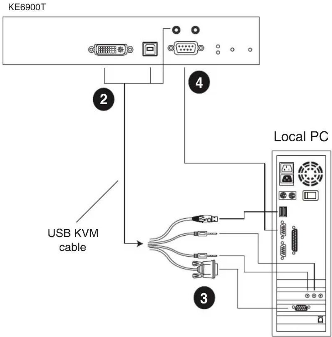
Note: The serial port on the Transmitter (shown above) connects to the computer; the serial port on the Receiver (not shown) connects to a serial device (optional).
KE6900A / KE6940A LAN Installation
Setting up the units on a network allows point-to-point, point-to-multipoint, and multipoint-to-multipoint computer to console operation by connecting multiple extender devices on the same TCP/IP LAN. Prior to setup we recommended laying out the plans for your KE installation using our performance guide (see Keys to Network Performance, page 339).
Note: 1. The units are preconfigured with factory-default network settings. If you install only one set of KE Series units, you do not need to change these default network settings. See Default IP Addresses, page 126, for further details.
2. In a network setup with multiple units, each Transmitter and Receiver must be configured with a unique IP address. See Network Configuration, page 125, for further details.
3. We recommended using 1000Mbps Gigabit Ethernet switches (wire speeds, non-blocking with 1Gbps/1.5Mpps performance per port) between KE Series devices installed on different LAN segments. 10/100Mbps switches might cause poor performance.
4. In multipoint configurations, the IGMP and flow control function of your network switches/hubs must be enabled to avoid the deterioration of data throughput. To ensure functionality use a layer 3 switch that supports IGMP queries.
5. If your network uses cascaded switches, please check to ensure the data throughput is sufficient.
6. To get the best performance, we suggest creating a private network for KE devices, as they are bandwidth-intensive devices.
7. The unit supports network redundancy. Where both LAN and SFP ports are connected, a network redundancy is established. Please note that if you use copper SFP modules, the module has to be removed for the unit to switch to the LAN port's network.
8. A keyboard or mouse with special functions may need to use the USB ports for advanced features to work (see USB Mode, page 203).
Make sure that all the equipment is powered off before the installation.
The installation is similar to that of KE6900A / KE6940A Point-to-Point Installation on page 82, with the difference in connecting the transmitter and
the receiver to a local area TCP/IP network. Refer to the diagrams on the following page and connect accordingly.
Repeat these steps for each Transmitter and Receiver you wish to install on the network then power on the computer(s).
KE6900A / KE6940A Network Installation Diagram 1 of 2
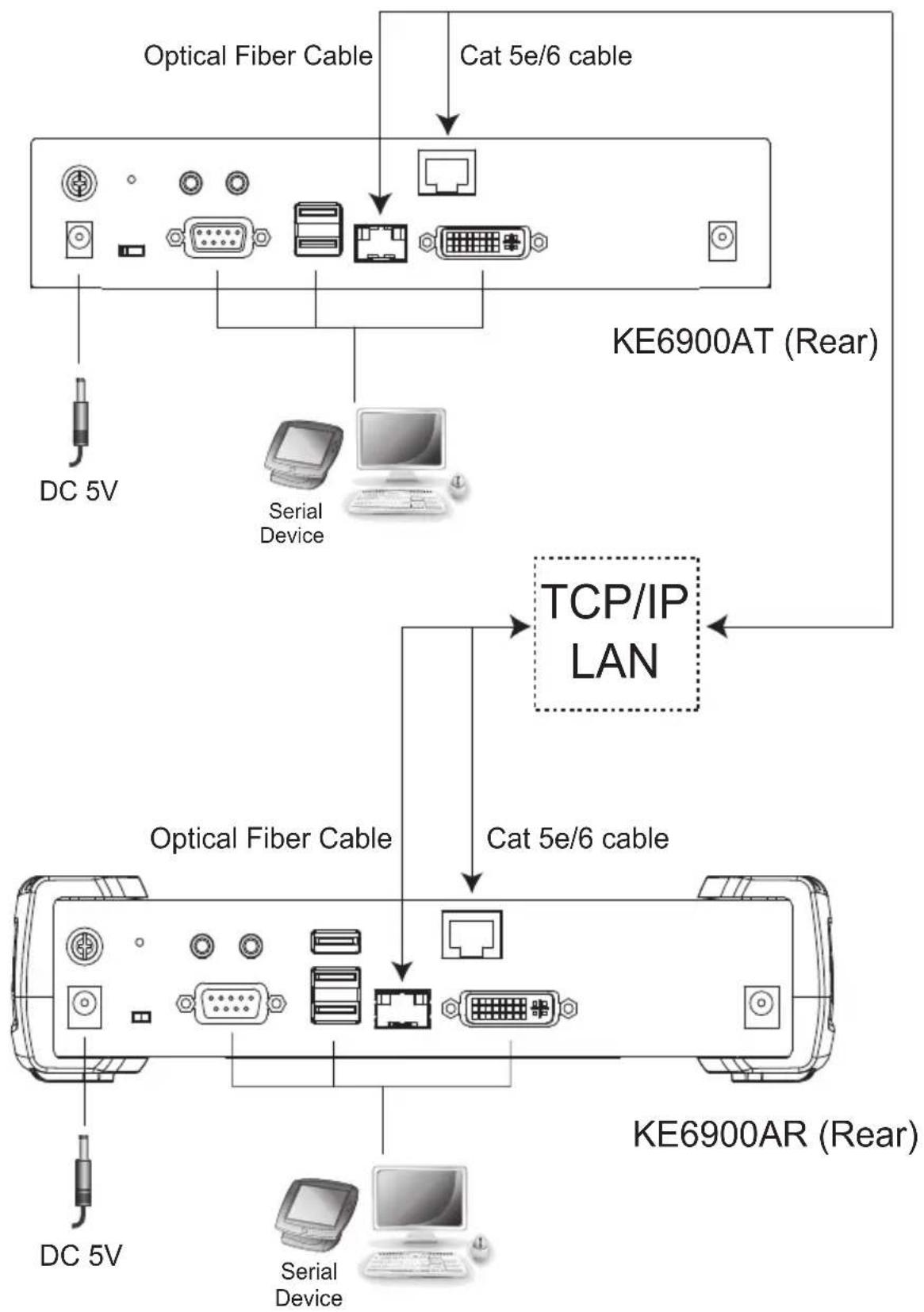
flowchart
graph TD
    A["DC 5V"] --> B["Optical Fiber Cable"]
    C["Serial Device"] --> D["KE6900AT (Rear)"]
    B --> E["KE6900AR (Rear)"]
    D --> E
    F["DC 5V"] --> G["Optical Fiber Cable"]
    H["Serial Device"] --> I["KE6900AR (Rear)"]
    J["PC"] --> K["TCP/IP LAN"]
    L["Router"] --> M["TC"]
    N["Router"] --> O["PC"]
    P["Router"] --> Q["PC"]
    R["Router"] --> S["PC"]
    T["Router"] --> U["PC"]
    V["Router"] --> W["PC"]
    X["Router"] --> Y["PC"]
    Z["Router"] --> AA["PC"]
KE6900A / KE6940A Network Installation Diagram 2 of 2
KE6900AT (Front)
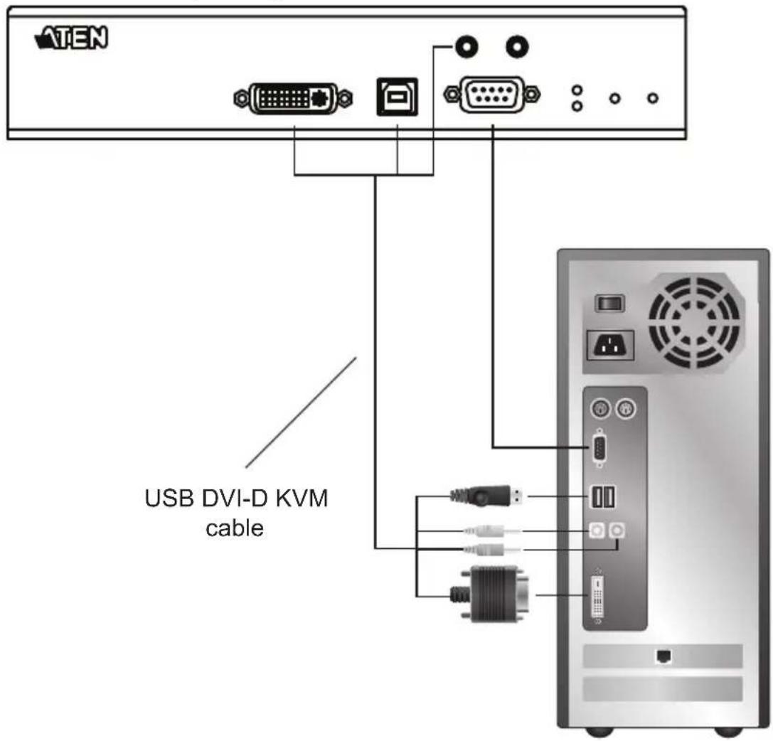
KE6910 / KE6912 LAN Installation
Setting up the units on a network allows point-to-point, point-to-multipoint, and multipoint-to-multipoint computer to console operation by connecting multiple KE6910 / KE6912 devices on the same TCP/IP LAN. Prior to setup we recommended laying out the plans for your KE installation using our performance guide (see Keys to Network Performance, page 339).
Note: 1. The units are preconfigured with factory-default network settings. If you install only one set of KE Series units, you do not need to change these default network settings. See Default IP Addresses, page 126, for further details.
2. In a network setup with multiple units, each Transmitter and Receiver must be configured with a unique IP address. See Network Configuration, page 125, for further details.
3. We recommended using 1000Mbps Gigabit Ethernet switches (wire speeds, non-blocking with 1Gbps/1.5Mpps performance per port) between KE Series devices installed on different LAN segments. 10/100Mbps switches might cause poor performance.
4. In multipoint configurations, the IGMP and flow control function of your network switches/hubs must be enabled to avoid the deterioration of data throughput. To ensure functionality use a layer 3 switch that supports IGMP queries.
5. If your network uses cascaded switches, please check to ensure the data throughput is sufficient.
6. To get the best performance, we suggest creating a private network for KE devices, as they are bandwidth-intensive devices.
Make sure that all the equipment is powered off before the installation.
The installation is similar to that of KE6910 / KE6912 Point-to-Point Installation on page 85, with the difference in connecting the transmitter and the receiver to a local area TCP/IP network. Refer to the diagrams on the following page and connect accordingly.
Repeat these steps for each Transmitter and Receiver you wish to install on the network then power on the computer(s).
KE6910 / KE6912 Network Installation Diagram 1 of 2
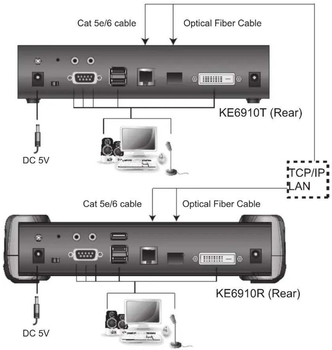
flowchart
graph TD
    A["KE6910T (Rear)"] -->|Cat 5e/6 cable| B["DC 5V"]
    A -->|Optical Fiber Cable| C["KE6910R (Rear)"]
    C -->|Cat 5e/6 cable| D["DC 5V"]
    C -->|Optical Fiber Cable| E["KE6910T (Rear)"]
    E --> F["TCP/IP LAN"]
    E --> G["KE6910R (Rear)"]
KE6910 / KE6912 Network Installation Diagram 2 of 2
KE6910T (Front)
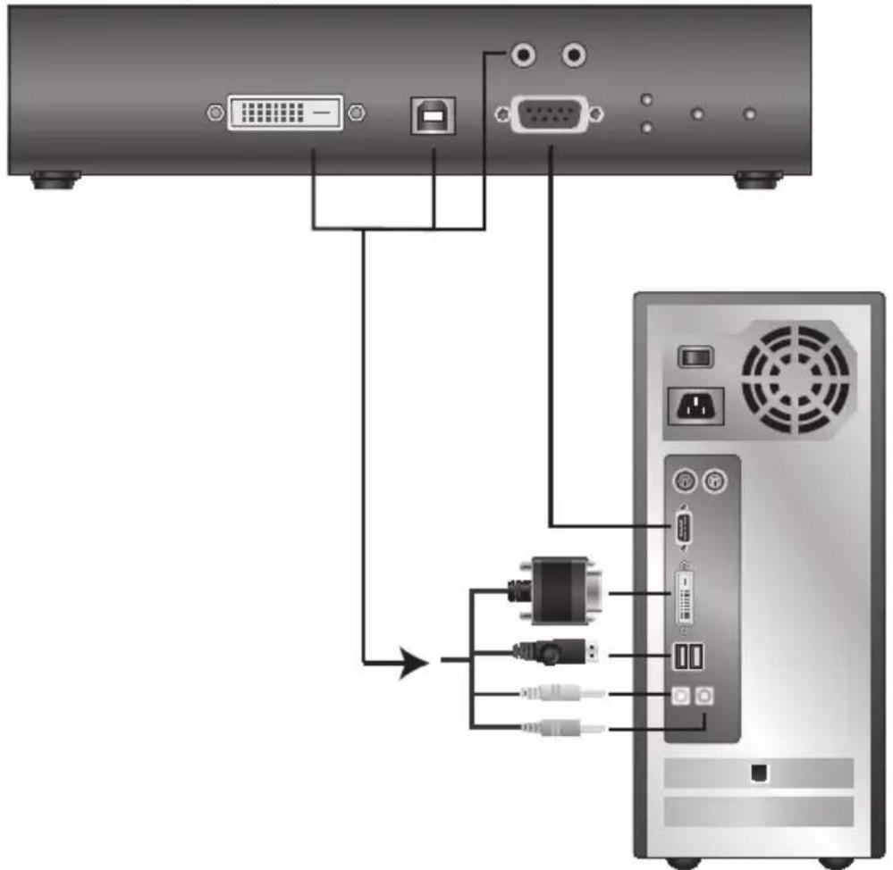
KE6920 / KE6922 LAN Installation
Setting up the units on a network allows point-to-point, point-to-multipoint, and multipoint-to-multipoint computer to console operation by connecting multiple KE6920 / KE6922 devices on the same TCP/IP LAN. Prior to setup we recommended laying out the plans for your KE installation using our performance guide (see Keys to Network Performance, page 339).
Note: 1. The units are preconfigured with factory-default network settings. If you install only one set of KE Series units, you do not need to change these default network settings. See Default IP Addresses, page 126, for further details.
2. In a network setup with multiple units, each Transmitter and Receiver must be configured with a unique IP address. See Network Configuration, page 125, for further details.
3. We recommended using 1000Mbps Gigabit Ethernet switches (wire speeds, non-blocking with 1Gbps/1.5Mpps performance per port) between KE Series devices installed on different LAN segments. 10/100Mbps switches might cause poor performance.
4. In multipoint configurations, the IGMP and flow control function of your network switches/hubs must be enabled to avoid the deterioration of data throughput. To ensure functionality use a layer 3 switch that supports IGMP queries.
5. If your network uses cascaded switches, please check to ensure the data throughput is sufficient.
6. To get the best performance, we suggest creating a private network for KE devices, as they are bandwidth-intensive devices.
Make sure that all the equipment is powered off before the installation.
The installation is similar to that of KE6920 / KE6922 Point-to-Point Installation on page 88, with the difference in connecting the transmitter and the receiver to a local area TCP/IP network. Refer to the diagrams on the following page and connect accordingly.
Repeat these steps for each Transmitter and Receiver you wish to install on the network then power on the computer(s).
Note: 1. The unit supports network redundancy. Where both LAN and SFP ports are connected, a network redundancy is established. Please note
that if you use copper SFP modules, the module has to be removed for the unit to switch to the LAN port's network.
- The KE6922's LAN port provides Power over Ethernet (PoE) functionality which supplies power to the unit when connected to a compatible PoE network switch.
- Power adapters are not provided with KE6922 units. Please contact your ATEN dealer to purchase additional power adapters, or use the Power over Ethernet (PoE) feature to supply power to KE6922 units.
- A keyboard or mouse with special functions may need to use the USB ports for advanced features to work (see USB Mode, page 203).
KE6920 / KE6922 Network Installation Diagram 1 of 2
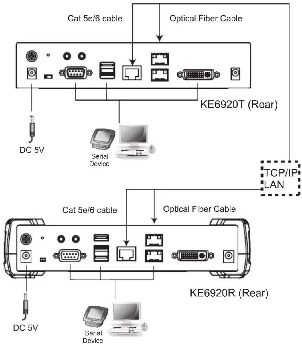
flowchart
graph TD
    A["KE6920T (Rear)"] --> B["Optical Fiber Cable"]
    B --> C["Cat 5e/6 cable"]
    B --> D["DC 5V"]
    B --> E["Serial Device"]
    B --> F["TCP/IP LAN"]
    B --> G["KE6920R (Rear)"]
    G --> H["Optical Fiber Cable"]
    H --> I["Cat 5e/6 cable"]
    H --> J["DC 5V"]
    H --> K["Serial Device"]
KE6920 / KE6922 Network Installation Diagram 2 of 2
KE6920T (Front)
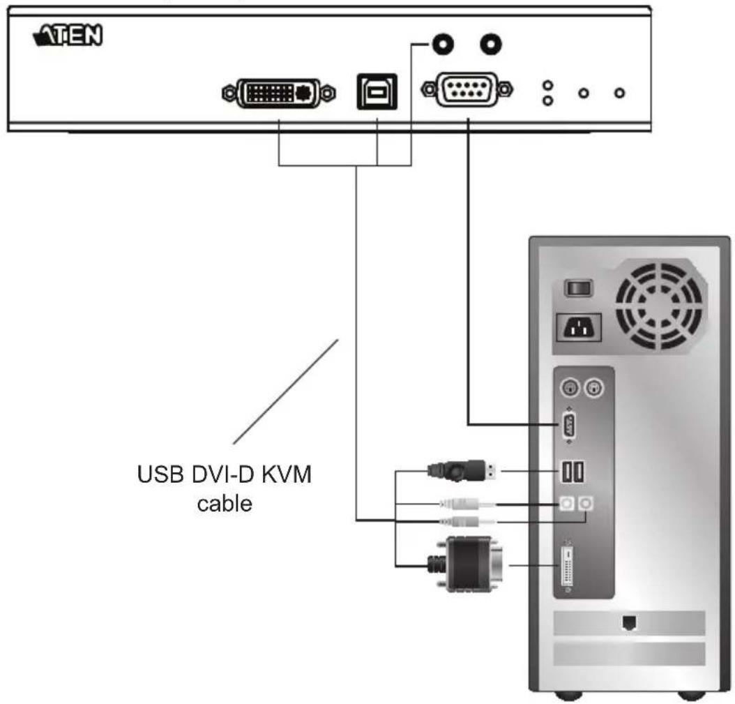
KE8950 / KE8952 LAN Installation
Setting up the units on a network allows point-to-point, point-to-multipoint, and multipoint-to-multipoint computer to console operation by connecting multiple KE8950 / KE8952 devices on the same TCP/IP LAN. Prior to setup we recommended laying out the plans for your KE installation using our performance guide (see Keys to Network Performance, page 339).
Note: 1. The units are preconfigured with factory-default network settings. If you install only one set of KE Series units, you do not need to change these default network settings. See Default IP Addresses, page 126, for further details.
2. In a network setup with multiple units, each Transmitter and Receiver must be configured with a unique IP address. See Network Configuration, page 125, for further details.
3. We recommended using 1000Mbps Gigabit Ethernet switches (wire speeds, non-blocking with 1Gbps/1.5Mpps performance per port) between KE Series devices installed on different LAN segments. 10/100Mbps switches might cause poor performance.
4. In multipoint configurations, the IGMP and flow control function of your network switches/hubs must be enabled to avoid the deterioration of data throughput. To ensure functionality use a layer 3 switch that supports IGMP queries.
5. If your network uses cascaded switches, please check to ensure the data throughput is sufficient.
6. To get the best performance, we suggest creating a private network for KE devices, as they are bandwidth-intensive devices.
Make sure that all the equipment is powered off. Refer to the installation diagram on the following page, and do the following:
- On the Transmitter side, plug the mouse, keyboard, HDMI monitor, microphone and speakers into the ports on the Console section of the KE8950T / KE8952T. Each port is marked with an appropriate icon to indicate itself.
- Connect the USB KVM cable provided to the KVM Ports on the front of the KE8950T / KE8952T.
-
Connect the other end of the USB KVM cable to the keyboard, video, mouse, speaker and microphone ports on the computer.
-
For control of serial devices, connect the RS-232 serial port on the Transmitter to a serial port on the computer.
- Connect a Cat 5e/6 cable to the LAN port, or a Gigabit Ethernet (GbE) optical fiber cable to the SFP port* to connect the KE8950T / KE8952T to the local area TCP/IP network.**
- Plug the power adapter into an AC source; and plug the other end into the KE8950T / KE8952T's Power Jack.***
- On the Receiver side, plug the mouse, keyboard, HDMI monitor, microphone, and speakers into the ports on the Console section of the KE8950R / KE8952R.****
- Connect a Cat 5e/6 cable to the LAN port, or a Gigabit Ethernet (GbE) optical fiber cable to the SFP port* to connect the KE8950R / KE8952R to the local area TCP/IP network.**
- Plug the power adapter into an AC source; and plug the other end into the KE8950R / KE8952R's Power Jack.***
- Use the OSD on the Receiver to configure the network settings for both devices (See Network Configuration, page 125).
- Repeat these steps for each Transmitter and Receiver you wish to install on the network.
- Power on the computer(s).
KE8950 / KE8952 Network Installation Diagram 1 of 2
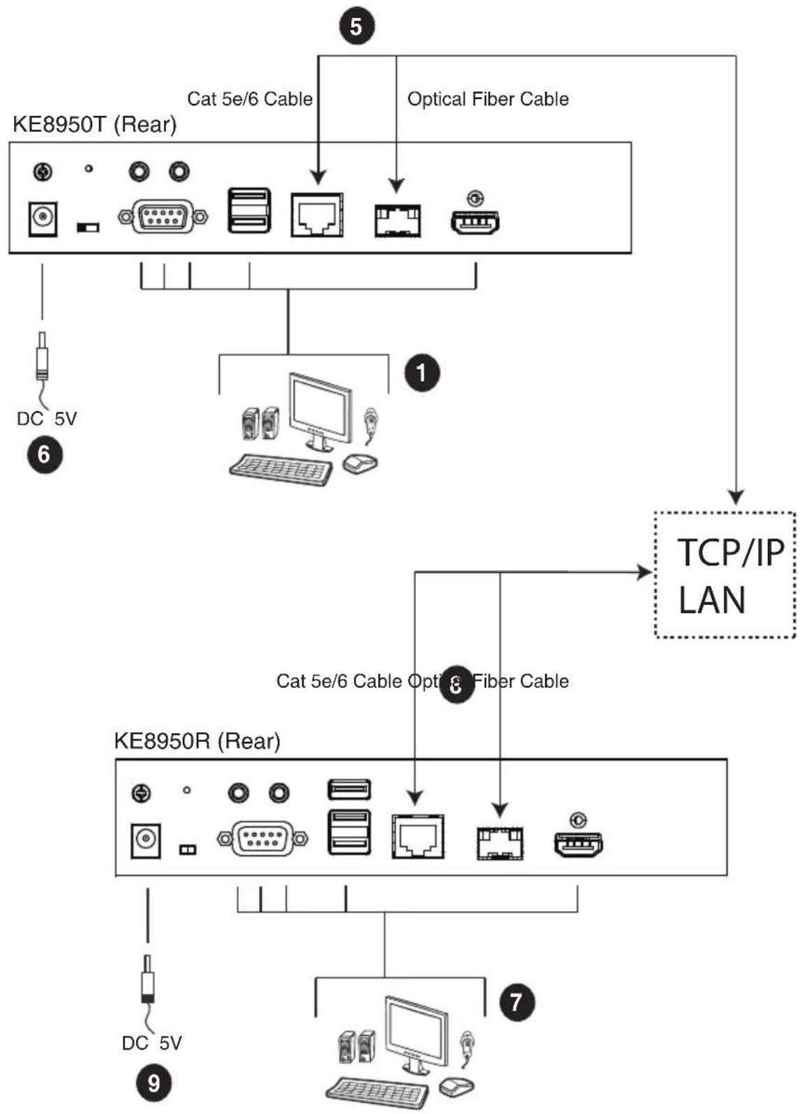
flowchart
graph TD
    A["KE8950T (Rear)"] -->|Cat 5e/6 Cable| B["Optical Fiber Cable"]
    A --> C["KE8950R (Rear)"]
    C --> D["TCP/IP LAN"]
    A --> E["DC 5V"]
    C --> F["DC 5V"]
    C --> G["DC 5V"]
    C --> H["DC 5V"]
    C --> I["DC 5V"]
    C --> J["DC 5V"]
    C --> K["DC 5V"]
    C --> L["DC 5V"]
    C --> M["DC 5V"]
    C --> N["DC 5V"]
    C --> O["DC 5V"]
    C --> P["DC 5V"]
    C --> Q["DC 5V"]
    C --> R["DC 5V"]
Note: Power adapters are not provided with KE8952 units. Please contact your ATEN dealer to purchase additional power adapters, or use the Power over Ethernet (PoE) feature to supply power to KE8952 units.
KE8950 / KE8952 Network Installation Diagram 2 of 2
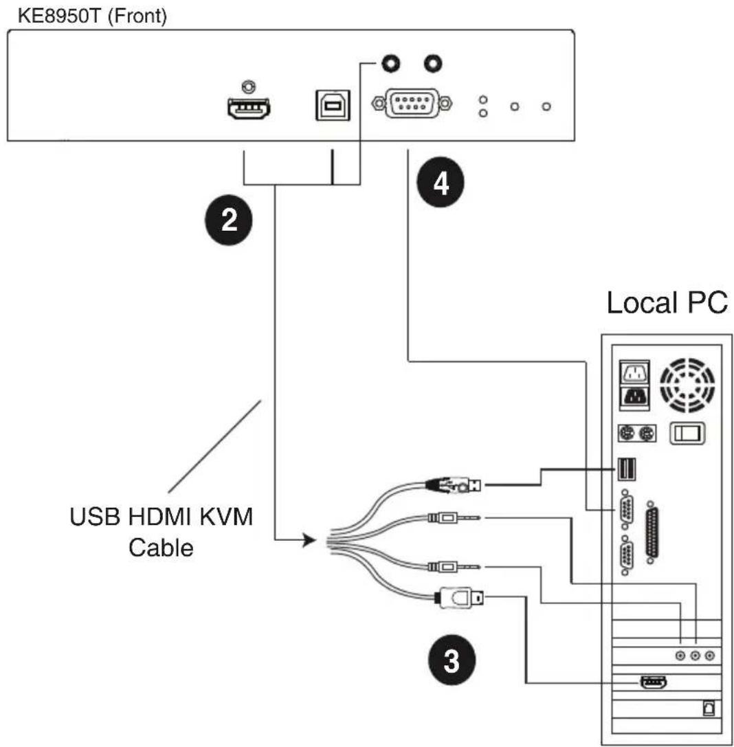
Note: The serial port on the Transmitter (shown above) connects to the computer; the serial port on the Receiver (not shown) connects to a serial device (optional).
KE9950 / KE9952 LAN Installation
Setting up the units on a network allows point-to-point, point-to-multipoint, and multipoint-to-multipoint computer to console operation by connecting multiple KE9950 / KE9952 devices on the same TCP/IP LAN. Prior to setup we recommended laying out the plans for your KE installation using our performance guide (see Keys to Network Performance, page 339).
Note: 1. The units are preconfigured with factory-default network settings. If you install only one set of KE Series units, you do not need to change these default network settings. See Default IP Addresses, page 126, for further details.
2. In a network setup with multiple units, each Transmitter and Receiver must be configured with a unique IP address. See Network Configuration, page 125, for further details.
3. We recommended using 1000Mbps Gigabit Ethernet switches (wire speeds, non-blocking with 1Gbps/1.5Mpps performance per port) between KE Series devices installed on different LAN segments. 10/100Mbps switches might cause poor performance.
4. In multipoint configurations, the IGMP and flow control function of your network switches/hubs must be enabled to avoid the deterioration of data throughput. To ensure functionality use a layer 3 switch that supports IGMP queries.
5. If your network uses cascaded switches, please check to ensure the data throughput is sufficient.
6. To get the best performance, we suggest creating a private network for KE devices, as they are bandwidth-intensive devices.
Make sure that all the equipment is powered off.
The installation is similar to that of KE6900 / KE6940 Point-to-Point Installation on page 79, with the difference in connecting the transmitter and the receiver to a local area TCP/IP network. Refer to the diagrams on the following page and connect accordingly.
Repeat these steps for each Transmitter and Receiver you wish to install on the network then power on the computer(s).
KE9950 / KE9952 Network Installation Diagram 1 of 2
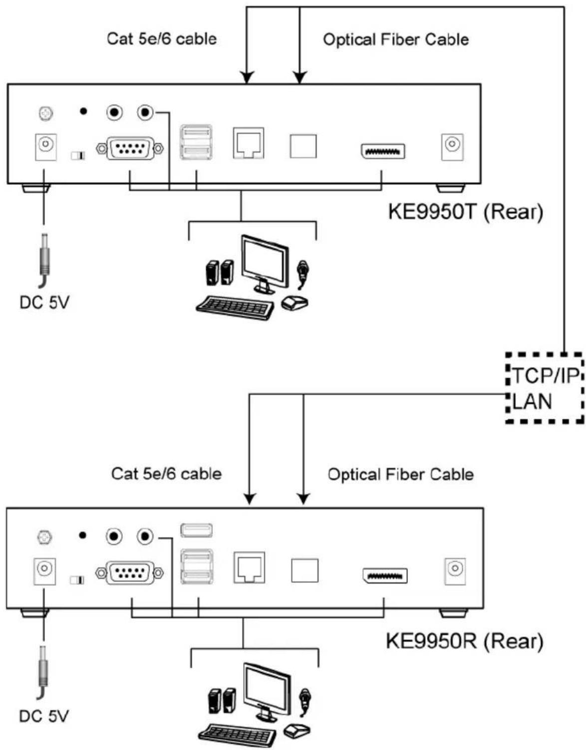
flowchart
graph TD
    A["KE9950T (Rear)"] -->|DC 5V| B["DC 5V"]
    A -->|Optical Fiber Cable| C["KE9950R (Rear)"]
    C -->|DC 5V| D["DC 5V"]
    A -->|TCP/IP LAN| E["KE9950T (Rear)"]
    E -->|Optical Fiber Cable| F["KE9950R (Rear)"]
KE9950 / KE9952 Network Installation Diagram 2 of 2
KE9950T (Front)
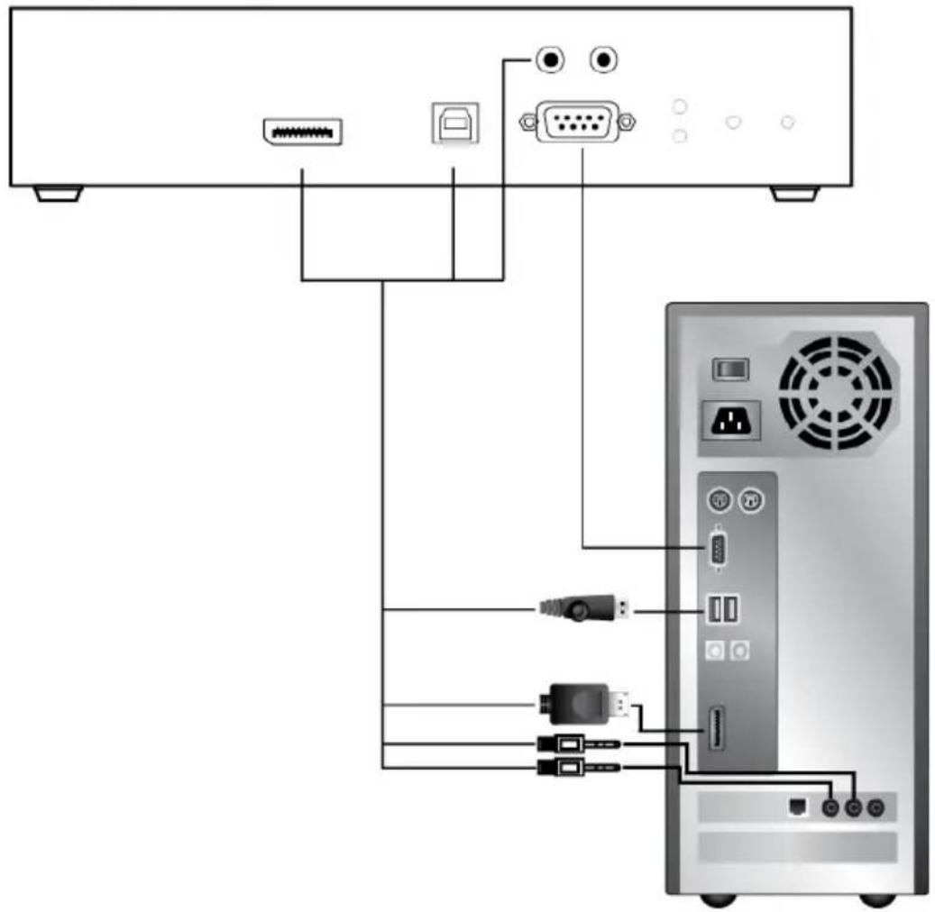
Network Configuration
This section provides instructions to configure the network settings with a fixed IP address, subnet mask, and default gateway. To use the IP Installer to configure the IP address, see IP Installer, page 326.
Note: 1. Both devices are preconfigured with factory-default network settings. If you install only one set of KE Series units, you do not need to change these default network settings. See Default IP Addresses, page 126, for further details.
2. In a network setup with multiple units, each transmitter and receiver must be configured with a unique IP address. See Network Configuration, page 125, for further details.
3. We recommended using 1000Mbps Gigabit Ethernet switches (wire speeds, non-blocking with 1Gbps/1.5Mpps performance per port) between devices installed on different LAN segments. 10/100Mbps switches might cause poor performance.
4. In multipoint configurations, the IGMP and flow control function of your network switches/hubs must be enabled to avoid the deterioration of data throughput. To ensure functionality use a layer 3 switch that supports IGMP queries.
5. If your network uses cascaded switches, please check to ensure the data throughput is sufficient.
6. To get the best performance, we suggest creating a private network for KE device, as they are bandwidth-intensive devices.
To configure the network settings, do the following:
- Setup the hardware and connect the Transmitter and Receiver to the local area network (see KE6900 / KE6940 LAN Installation, page 103, or KE8950 / KE8952 LAN Installation, page 118).
- From the Receiver, tap the Scroll Lock key twice to invoke the OSD.
- Select the Receiver or Transmitter from the sidebar menu.
- Enter the password and click Configure.
The default password is: password.
- From the Network tab select Set IP address manually and enter the following:
- IP Address– sets the IP address for the KE device. Key in a valid unique IP address.
Note: See Default IP Addresses, page 126, for the preconfigured factory-default settings.
- Subnet Mask – sets the subnet mask for the KE device. Key in a valid subnet mask value.
Note: The default setting is 255.255.255.0
- Default Gateway—sets the default gateway for the KE device. Key in a valid default gateway.
6. Click Save.
Exit OSD
To exit the OSD, press [Esc] on the keyboard, click Logout; tap the Scroll Lock key twice; or return to the OSD main page and press the front panel OSD pushbutton (Receiver only).
At this point the Receiver can connect to the Transmitter to access the remote computer (see Connecting, page 146 for instructions).
Default IP Addresses
The preconfigured factory-default IP addresses for the KE Series devices are as follows:
Transmitters - 192.168.0.61
Receivers-192.168.0.60
KE I/O Ports
The following table provides the I/O port use of KE Series devices.
| Device Port Number | ||
| KE Matrix Manager (TCP) HTTP 8080 | ||
| HTTPS 8443 | ||
| Device TCP 9110 | ||
| CLI9111 | ||
| Redundancy 9120 | ||
| Database Service 1527 | ||
| KE Matrix Manager (UDP) Port 9110 | ||
| Broadcast 9000 | ||
| KE TX/RX Device (TCP) | Manager | 9110 |
| Service | 9000 | |
| Telnet | 23 | |
| SSH | 22 | |
| KE TX Device (TCP) | VM | 9001 |
| vUSB | 9002 | |
| Serial | 9003 | |
| USB Access Mode | 9009 | |
| KE RX Device (TCP) | CLI | 9130 |
| KE TX/RX Device (UDP) | Manager | 9110 |
| Service | 9000 | |
| Array Mode | 9120 | |
| Video | 0xFE00(65024) - 0xFE03(65027) | |
| Audio | 0xFE04(65028) - 0xFE05(65029) | |
LED Display
Both the Transmitter and Receiver have front panel LEDs to indicate their operating and power status, as explained in the table below:
| LED Indication | |
| LAN This LED indicates the network status.◆ Lights when connected to the LAN and blinks when the Ethernet connection is active:◆ Orange: 10 Mbps◆ Orange + Green: 100 Mbps◆ Green: 1000 Mbps◆ Off when not connected to the LAN. | |
| Power | ◆ Lights blue when the unit is powered on.◆ OFF when power is off. |
| Local | ◆ Lights green to Indicate the Transmitter has KVM focus of the computer |
| Remote | ◆ Lights green to Indicate the Receiver has KVM focus of the computer. |
Authentication Lock (KE6910 / KE6912 only)
The KE6910/KE6912 extenders feature the Authentication Lock function. When accidental power cut happens, the function allows the user to retain his/her settings as was shown before the power cut. The user keeps the same authentication and display.
This function can be configured in General on page 225.
Overview
This chapter provides instructions to configure and operate KE Series devices using the local On Screen Display (OSD). To configure the network settings with the OSD, see Network Configuration, page 125.
Invoking the OSD
The On Screen Display (OSD) is a keyboard/mouse-driven application on the receiver used to configure the transmitter and receiver settings. Once the receiver has discovered the transmitter over a network* or Ethernet cable connection, you can use the OSD on the receiver to configure the transmitter.
To invoke the OSD, press the OSD pushbutton on the front of the receiver, or from the keyboard tap the Scroll Lock key twice. The OSD main page will appear (see , page 130).
To exit the OSD, press [Esc] on the keyboard; click Logout; tap the Scroll Lock key twice; or return to the OSD main page and press the OSD pushbutton on the front of the receiver. The OSD disappears and the computer desktop screen or the System Login prompt is displayed.
Note: 1. For the Receiver to discover the Transmitter over a network, both must be on the same subnet of the LAN.
2. To change the OSD hotkeys, see page 145.
3. If the keyboard/mouse won't work when the OSD is invoked, see USB Mode, page 203.
Touch Screen Calibration
If you're using a touch screen monitor and the OSD appears off center, you can use the blinking + at each corner to adjust the position of the OSD.
OSD Hotkeys
The OSD hotkeys navigate the Receiver's OSD screens. The hotkeys work after logging in from the System Login screen (see page 146) but not the OSD Configuration screen. Pressing a hotkey will immediately take you to the corresponding OSD screen.
| Hotkey OSD Screen Page | ||
| [F1] Connections Page 1 in List Mode 148 | ||
| [F2] Connections Page 1 in Array Mode 151 | ||
| [F3] Profile Page 1 153 | ||
| [F5] Push Content Page 1 154 | ||
| [F6] Pull Content Page 1 156 | ||
| [F7] Receiver > Properties 133 | ||
| [F8] | User Preferences | 145 |
| [F9] | OSD Login Screen (logs user off) | 146 |
Microphone Hotkey
You can switch microphone access between Receivers with a hotkey:
- Press and hold down
- Press and release [-].
- Release [Num Lock].
- Press 1.
Press the Esc key to cancel.
OSD Interface
After you invoke the OSD, the main page appears:
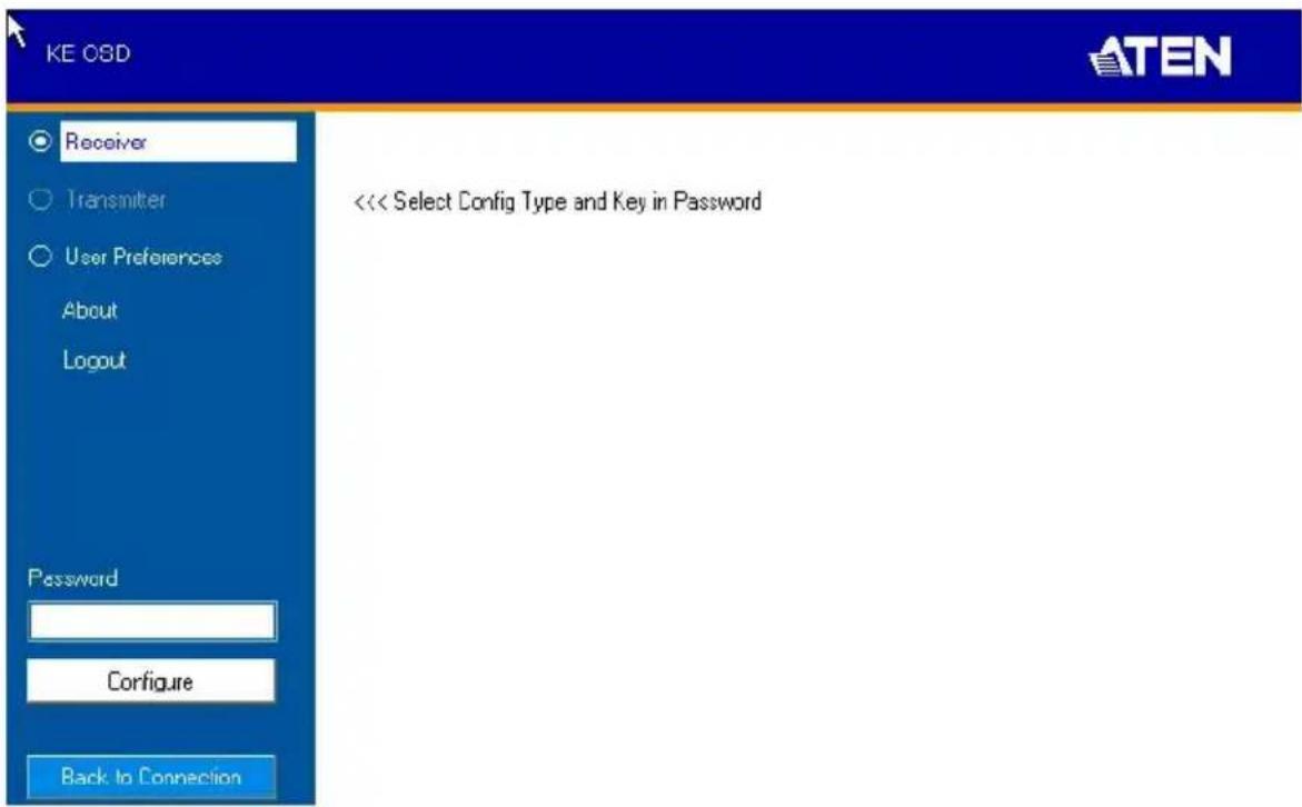
Note: A password is required to enter the OSD. The default password is: password. For security purposes, we recommend you change this to something unique.
The OSD components are described in the table below:
| No. | Item Description | |
| 1 | Receiver Select this radio button, enter a password, and click Configure to enter the Receiver Configuration screen. | |
| 2 | Transmitter Select this radio button, enter a password, and click Configure to enter the Transmitter Configuration screen.Note: Receiver must first discover the transmitter over the network for this option to be available. | |
| 3 | User Preferences Select this radio button, enter a password, and click Configure to enter the User Preferences screen. | |
| 4 | About About provides information regarding the OSD version. | |
| 5 | Password Input the OSD password and click Configure to enter the selected configuration screen. See note for password. | |
| 6 | Configure | After entering a password, click Configure to enter the selected configuration screen. |
| 7 | B a c k Connection | Clicking this button exits the OSD and returns you to the computer's video display. |
Receiver Configuration
When you select the Receiver radio button and click Configure to login, the Network tab appears:
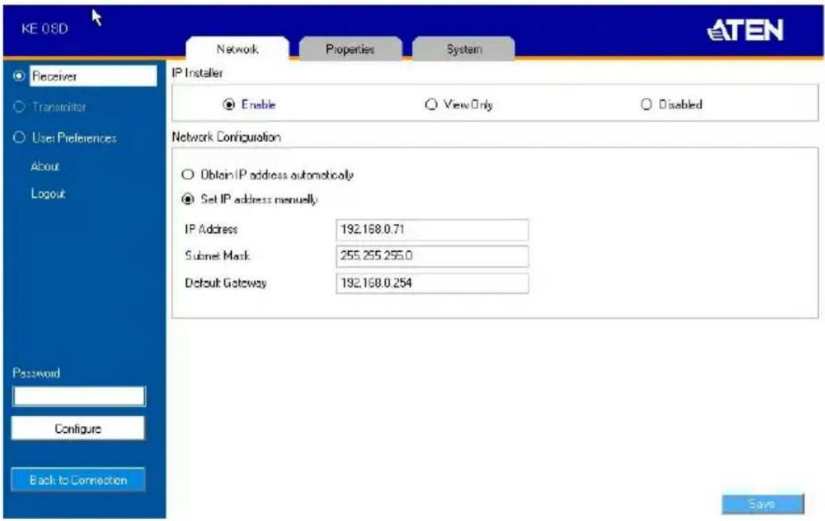
Network
The Network tab allows you to configure the Receiver's IP address settings:
| Item Description | |
| IP Installer The IP | Installer is an external Windows-based utility for assigning an IP address to the device. Click one of the radio buttons to select Enable, View Only, or Disable for the IP Installer utility. See IP Installer, page 326 for instructions.Note: For security, we strongly recommend that you set this to View Only or Disable after each use. |
| Network Configuration | For dynamic IP address assignment (DHCP), select the Obtain IP address automatically radio button.To specify a fixed IP Address, Subnet Mask, and Default Gateway select the Set IP address manually radio button and fill in the fields with values appropriate for your network.For help configuring network settings with the OSD, see Network Configuration, page 125. |
After entering the information, click Save.
Properties
There are two versions of Properties for KE Series, a Regular Version, and a Slim Version.
Note: KE8900ST, KE8900SR, and KE9900ST are Slim Version.
Regular Version
The Properties tab allows you to configure the Receiver's settings:
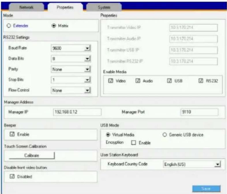
| Item Description | |
| Mode Select Extender mode for simple one-to-one (Transmitter to Receiver) setups that are managed with the Receiver's OSD menu.Select Matrix mode to manage devices and connections from the KE Matrix Manager web GUI. This mode is for advanced administration of Transmitter to Receiver connections (see Browser / Telnet Operation, page 169). | |
| Properties | If you selected Extender mode (above) set the Transmitter IP address for the Receiver's Video, Audio, USB, and RS232 source signals.If you selected Matrix mode (above) the Properties will be grayed out. Use Channels to configure the Transmitter connections (see Browser / Telnet Operation, page 169). |
| RS232 Settings | Configure the serial device settings for the Receiver. The default settings are: Baud Rate: 9600 Parity: None Data Bits: 8 bits Stop bits: 1 bit Flow Control: None |
| Enable Media Select which type of media the Receiver can stream from Transmitters: Video, Audio, USB, and RS232. For KE8950 Series models, use the radio button to set the source of the audio signal: HDMI, Analog, or Both. | |
| Manager Address | Set the IP address and Port number of the computer running the KE Matrix Manager software. The default port number is 9110. |
| Beeper Check this | box to allow the Receiver to beep when configuration changes are made to it. |
| Touch Screen Calibration | Use this button to calibrate the surface of a USB touch screen connected to the unit. When the calibration screen appears, touch the flashing + symbol at each corner until the process is complete. |
| USB Mode Select | the type of USB device you will connect to the USB ports:Virtual Media: Only select this option if you are plugging a USB disk into the USB ports. This will give you the highest data transfer speeds but will not allow other USB devices plugged into the USB ports to work. When Receivers connected to the same transmitter mount or unmount USB disk drives, the keyboard and mouse operations will experience a brief delay. Transmitters can support up to 12 virtual media connections at the same time (keyboard/mouse included).vUSB (Generic USB device): Use this option to plug USB peripherals* into the USB ports. This option also allows a keyboard and mouse with special functions to plug into the USB ports for console use. Use this only if the special functions of the keyboard or mouse are required but do not work when plugged into the console ports. When the keyboard and mouse are plugged into the USB ports, they will not work within the OSD menus. To work within the OSD menus, the keyboard and mouse must be plugged into the console ports. KE6900ST/KE8900ST/KE9900ST transmitters do not support vUSB (Generic USB Device) mode. In this mode, KE6900/KE6940 transmitters supports up to 2 USB connections, KE8950/KE8952 transmitters support up to 5 USB connections (keyboard/mouse excluded), and KE8900SR supports 1 vUSB connection.Encryption: Check this box to encrypt USB drives plugged into the USB ports.Note: This USB port does not support isochronous endpoints, therefore USB peripherals that stream audio or video data, such as speakers or webcams, will not work. |
| Receiver Keyboard | Use the Keyboard Country Code drop-down menu to select the Receiver's language keyboard for use in the OSD. |
| Disable front video button (KE6910 / 6912 only) | You can enable or disable the function (select video mode or graphic mode) of the video pushbutton on the front of the receiver.Check Disable to disable (checked by default).Uncheck Disable to enable. |
After entering the information, click Save.
Slim Version
The Properties tab allows you to configure the Receiver's settings:
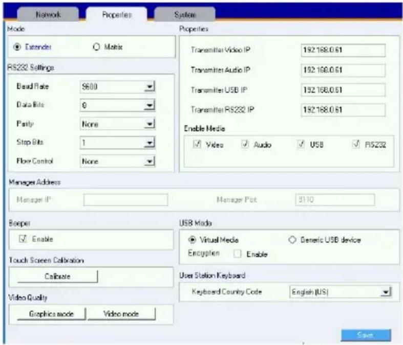
| Item Description | |
| Mode Select Extender mode for simple one-to-one (Transmitter to Receiver) setups that are managed with the Receiver's OSD menu.Select Matrix mode to manage devices and connections from the KE Matrix Manager web GUI. This mode is for advanced administration of Transmitter to Receiver connections (see Browser / Telnet Operation, page 169). | |
| Properties | If you selected Extender mode (above) set the Transmitter IP address for the Receiver's Video, Audio, USB, and RS232 source signals.If you selected Matrix mode (above) the Properties will be grayed out. Use Channels to configure the Transmitter connections (see Browser / Telnet Operation, page 169). |
| RS232 Settings C | Configure the serial device settings for the Receiver. The default settings are:Baud Rate: 9600Parity: NoneData Bits: 8 bitsStop bits: 1 bitFlow Control: None |
| Enable Media Select which type of media the Receiver can stream from Transmitters: Video, Audio, USB, and RS232. For KE8950 Series models, use the radio button to set the source of the audio signal: HDMI, Analog, or Both. | |
| Manager Address | Set the IP address and Port number of the computer running the KE Matrix Manager software. The default port number is 9110. |
| Beeper Check this box to allow the Receiver to beep when configuration changes are made to it. | |
| Touch Screen Calibration | Use this button to calibrate the surface of a USB touch screen connected to the unit. When the calibration screen appears, touch the flashing + symbol at each corner until the process is complete. |
| USB Mode Select the type of USB device you will connect to the USB ports:Virtual Media: Only select this option if you are plugging a USB disk into the USB ports. This will give you the highest data transfer speeds but will not allow other USB devices plugged into the USB ports to work. When Receivers connected to the same transmitter mount or unmount USB disk drives, the keyboard and mouse operations will experience a brief delay. Transmitters can support up to 12 virtual media connections at the same time (keyboard/mouse included).vUSB (Generic USB device): Use this option to plug USB peripherals* into the USB ports. This option also allows a keyboard and mouse with special functions to plug into the USB ports for console use. Use this only if the special functions of the keyboard or mouse are required but do not work when plugged into the console ports. When the keyboard and mouse are plugged into the USB ports, they will not work within the OSD menus. To work within the OSD menus, the keyboard and mouse must be plugged into the console ports. KE6900ST/KE8900ST/KE9900ST transmitters do not support vUSB (Generic USB Device) mode. In this mode, KE6900/KE6940 transmitters supports up to 2 USB connections; and KE8950/KE8952 transmitters support up to 5 USB connections (keyboard/mouse excluded).Encryption: Check this box to encrypt USB drives plugged into the USB ports.Note: This USB port does not support isochronous endpoints, therefore USB peripherals that stream audio or video data, such as speakers or webcams, will not work. | |
| Receiver Keyboard | Use the Keyboard Country Code drop-down menu to select the Receiver's language keyboard for use in the OSD. |
| Video Quality (KE8900ST / 8900SR / 9900ST) | You can select video mode or graphic mode for the video quality, the Slim Version KE Series does not have a phsycial pushbutton on the front of the receiver. |
After entering the information, click Save.
System
The System tab allows you to configure the Receiver's general settings:
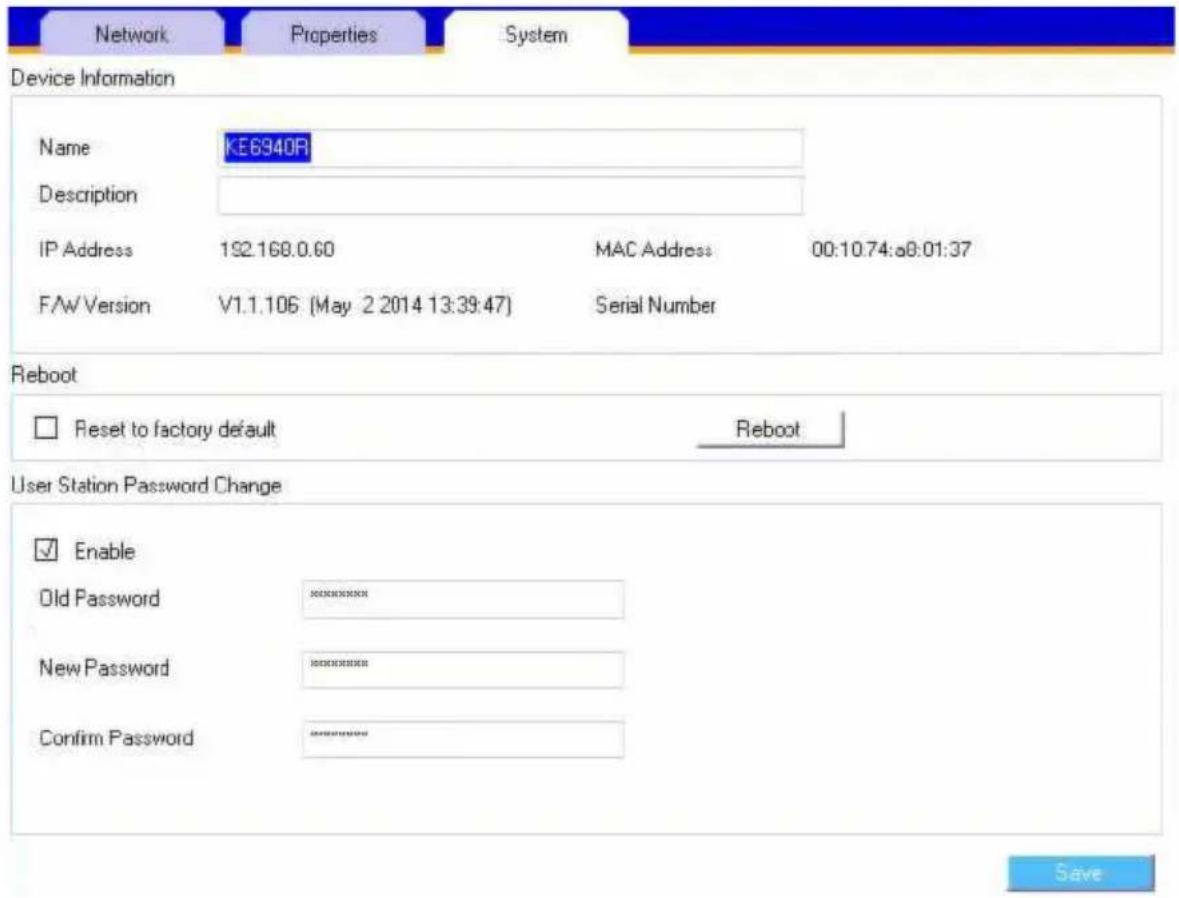
| Item Description | |
| Device Information | Enter the Name, and Description of the Receiver. It also displays the IP Address, MAC Address, F/W Version, and Serial Number of the Receiver. |
| Reboot | Check the box and click Reboot to reset the Receiver's settings back to the factory default. All custom settings (but not the login information) will be lost. |
| Receiver Password Change | Check Enable to require a password for access to the Receiver's OSD configuration screen. Enter the Old Password, enter a New Password, and confirm the new password in the Confirm Password box. |
After entering the information, click Save.
Transmitter Configuration
When you select the Transmitter radio button and click Configure to login, the Network tab appears:
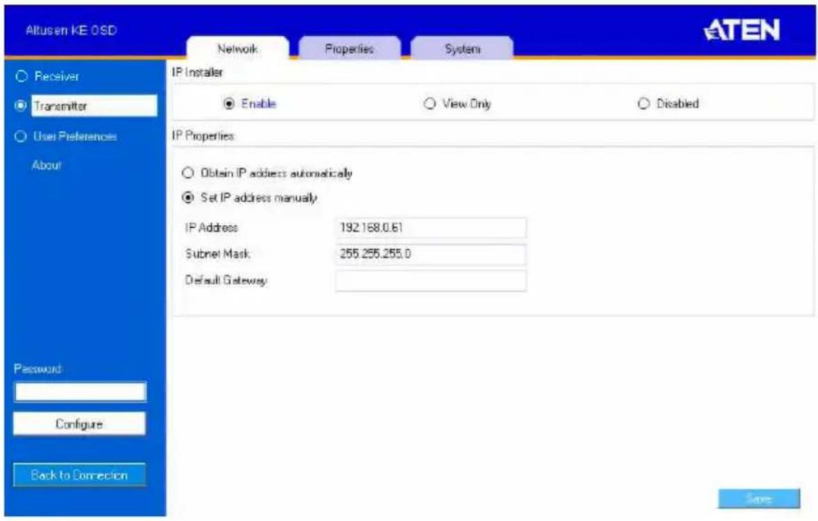
Network
The Network tab allows you to configure the Transmitter's IP address settings:
| Item Description | |
| IP Installer The IP | Installer is an external Windows-based utility for assigning an IP address to the device. Click one of the radio buttons to select Enable, View Only, or Disable for the IP Installer utility. See IP Installer, page 326 for instructions.Note: For security, we strongly recommend that you set this to View Only or Disable after each use. |
| Network Configuration | For dynamic IP address assignment (DHCP), select the Obtain IP address automatically radio button.To specify a fixed IP Address, Subnet Mask, and Default Gateway select the Set IP address manually radio button and fill in the fields with values appropriate for your network.For help configuring network settings with the OSD, see Network Configuration, page 125. |
After entering the information, click Save.
Properties
The Properties tab allows you to configure the Transmitter's extender settings:
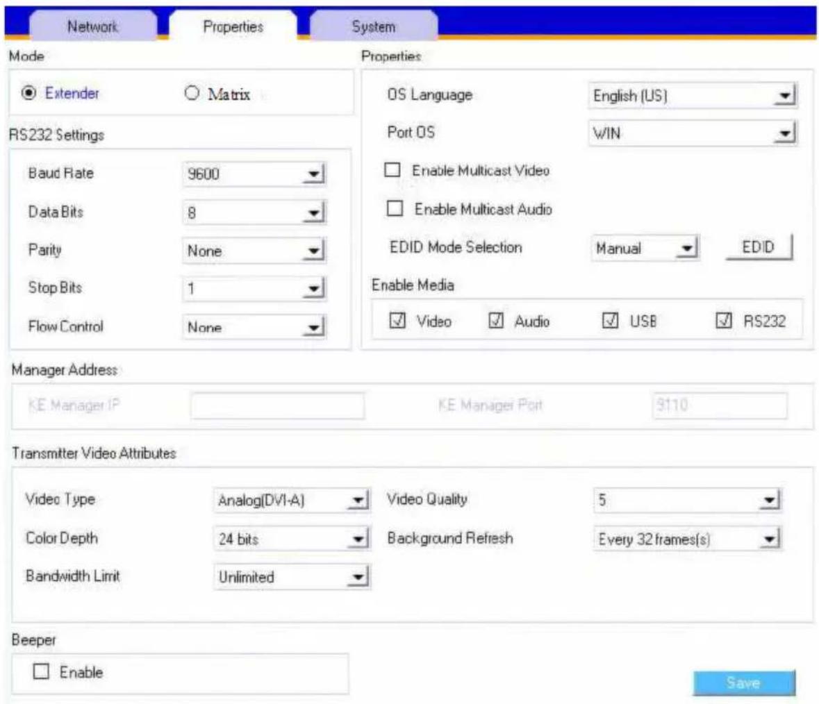
| Item Description |
| Mode Select Extender mode for simple one-to-one (Transmitter to Receiver) setups that are managed with the Receiver's OSD menu.Select Matrix mode to manage devices and connections from the KE Matrix Manager web GUI. This mode is for advanced administration of Transmitter to Receiver connections (see Browser / Telnet Operation, page 169). |
| Item Description | |
| Properties | Port OS: Use the drop-down menu to select the operating system of the computer connected to the Transmitter.OS Language: Use the drop-down menu to select the operating system language of the computer connected to the Transmitter.Enable Multicast Video: Check this box to allow a broadcast of the Transmitter's video signal to be sent out to multiple Receivers.Enable Multicast Audio: Check this box to allow a broadcast of the Transmitter's audio signal to be sent out to multiple Receivers.EDID Mode Selection: EDID contains a display's basic information and is used by the source device to utilize the best resolution across different monitors. When Manual or Remix is selected, the Receiver's OSD will have a button allowing the local EDID setting to be configured for the connection. Select how you want the source device to acquire the display's EDID:Default: EDID is set to the default ATEN configuration. This setting must be used when connecting KE6900 devices to KE8950 devices.Auto: Checks the EDID of all connected displays and the ATEN default EDID to use the best common resolution for all displays.Manual: Manually set the EDID configuration from the Connections Page (see page 148).Remix: Manually checks the EDID of all connected displays and the ATEN default EDID to use the best common resolution for all displays (see page 148). |
| Enable Media | Select which type of media the Transmitter can stream to Receivers: Video, Audio, USB, and RS232. |
| RS232 Settings C | Configure the serial device settings for the Transmitter. The default settings are:Baud Rate: 9600Parity: NoneData Bits: 8 bitsStop bits: 1 bitFlow Control: None |
| Manager Address | Set the IP address and Port number of the computer running the KE Matrix Manager software. The default port number is 9110. |
| TransmitterVideo Attributes | To set the Transmitter's video settings:Video Type: Select the DVI video connector being used by the display: Digital (DVI-D) or Digital (DVI-I). This option is available for KE6900, KE6940, KE6900A, KE6940A units and will be grayed out for other models.Color Depth: Select the number of bits to use for the color depth: 24, 16, or 8. This is the number of bits used to describe the color of a single pixel. A bit depth determines the number of colors that can be displayed at one time.Bandwidth Limit: Select the maximum bandwidth that the Transmitter can use to transmit video over the network. A lower bandwidth setting transmits lower quality video; a higher bandwidth setting sends higher quality video but this can affect network speed.Video Quality: Select the video quality to use. 5 is the highest video quality, and 1 is the lowest video quality. Options are: 1~5.Background Refresh: Sets how often the Transmitter refreshes the background image on the connected display. Options are to refresh every 256,128, 64, 32,16, or 0 frames. |
| Beeper Check this | box to allow the device to beep every time a configuration change is made. |
| Occupy Timeout S | Set a time threshold for devices whose Access Mode has been set to Occupy (see Access Type, page 198). If there is no activity from the Receiver occupying the port for the amount of time set here, the Receiver is timed out and the port is released. The first Receiver to send keyboard or mouse input after the port has been released gets to occupy the port. Input a value from 1 to 240 seconds. |
After entering the information, click Save.
System
The System tab allows you to configure the Transmitter's general settings:
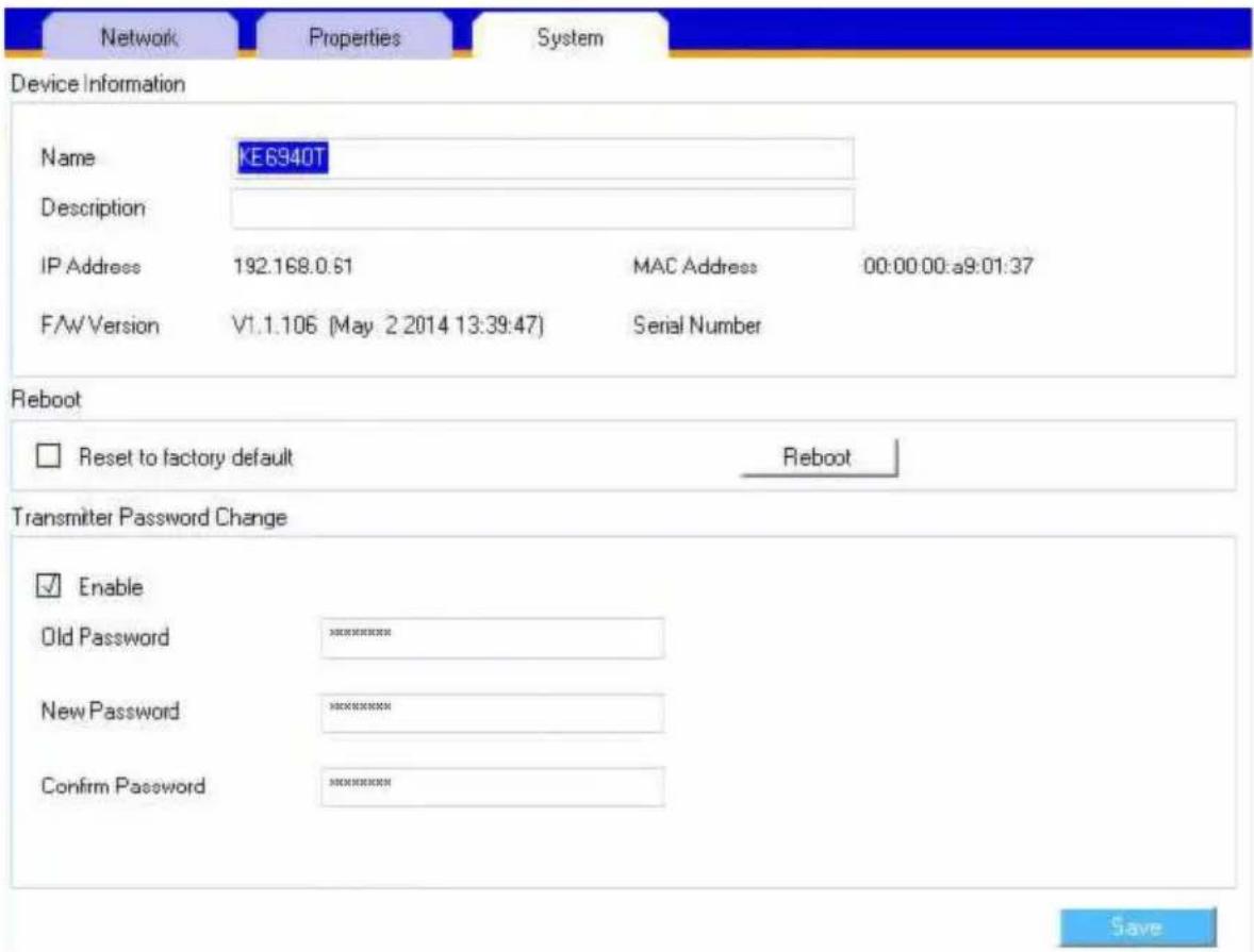
| Item Description | |
| Device Information | Enter the Name and Description of the Transmitter. It also displays the IP Address, MAC Address, F/W Version, and Serial Number of the Transmitter. |
| Reboot | Check the box and click Reboot to reset the Transmitter's settings back to the factory default. All custom settings (but not the login information) will be lost. |
| Transmitter Password Change | Check Enable to require a password for access to the Transmitter's OSD configuration screen. Enter the Old Password, enter a New Password, and confirm the new password in the Confirm Password box. |
After entering the information, click Save.
User Preferences
When you select the User Preferences radio button and click Configure to login, the configuration screen appears:
![KE OSD ATEN Receiver Transmitter User Preferences About Logout Password Configure Back to Connection User Password Change Old Password New Password Confirm Password ODD Settings OSD Language English OSD Hockey [clr][ctrl] Logout Timeout 30 min (0-180) Disabled Screen Blanker 0 min (0-30) Disabled Save](/content/2026/05/1059622/images/739e6db42c3cda7de9d6c7e2b3bdced4b040deaf8561d523ceb95db7a6e389bd.jpg)
| Item Description | |
| User Password Change | This section allows you to change the OSD password:1. Key in the old password in the Old password field.2. Key in the new password in the New password field.3. Key in the new password again in the Confirm password field. |
| OSD Language Click the drop-down menu to select the language you want to use for OSD sessions. Choices are: English, Chinese (Simplified), Chinese (Traditional), Japanese, Korean, Dutch, French, Spanish, Portuguese, and Russian. | |
| OSD Hotkey Select the hotkey combination to invoke the OSD screen. | |
| Logout Timeout If | there is no user input for the amount of time set with this function, the user is automatically logged out of the OSD. A login is necessary before the OSD can be accessed again. |
| Screen Blanker Set how many minutes the OSD waits when a session is idle before turning off the display. | |
When you have made your choices, Click Save.
Connecting
If the Receiver is set to Extender mode, the video screen of the remote computer will appear automatically when you exit the OSD (press Esc to exit). In Matrix mode you will see the System Login screen, which provides access to the Connection Page by entering a username and password:
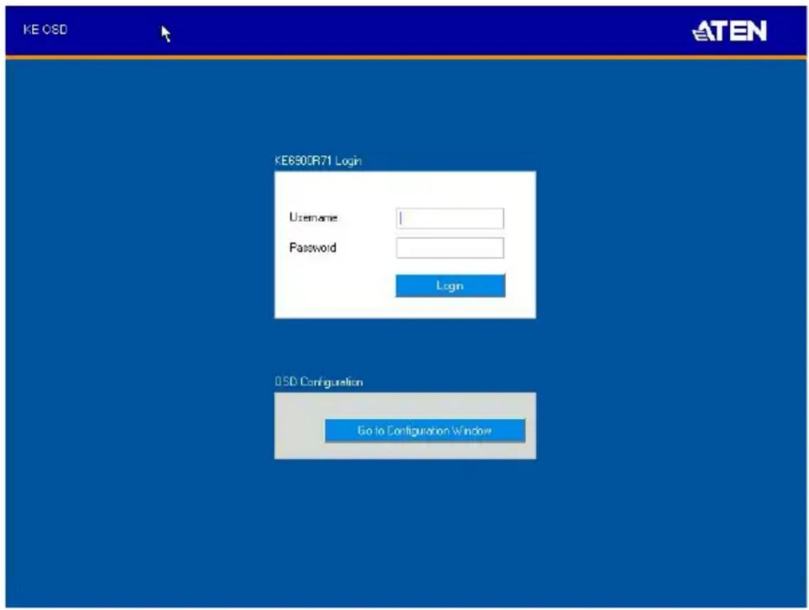
Note: 1. If you are the administrator, and are logging in to transmitter, receiver or any of the modes for the first time, refer to Logging in for the First Time on page 147.
2. If the Receiver does not require a login, click Login to system (see Login Required, under Basic, page 202).
3. For information about Extender and Desktop/Matrix modes, see Mode, page 133.
After you login the Connection Page appears, as shown on the next page.
Logging in for the First Time
If you are the administrator, and are logging in for the first time (transmitter, receiver or any of the modes), use the default username (administrator) and the default password (password).
For security purposes, the system will prompt you to change the login password immediately as shown below:
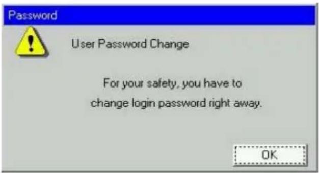
Click OK and change the password in the dialog box shown below:
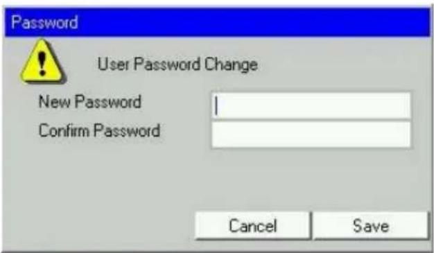
Enter the password and confirm it in the next field. The password must be different from your original password.
Connections Page
After you have successfully logged in the Connection Page appears:
List Mode
![KE 08D Connection Page 1 Profile Page 1 Push Content Page 1 Full Content Page 1 Administrator: Welcome to KE Channel Name Description Connect KE6940T67 [NAUS] Exclusive Occupy Share View Only Exit KE6940T1 [NAUS] Exclusive Occupy Share View Only Exit KE8950T61 [NAUS] Exclusive Occupy Share View Only Exit GroupTX [N] Exclusive Occupy Share View Only Exit VirtualTX [NAUS][net] Exclusive Occupy Share View Only Exit GroupTX1 [N] Exclusive Occupy Share View Only Exit K<< >> >>| Favorites Array Mode Logout Go to Configuration Window](/content/2026/05/1059622/images/31f0a37749932f65df431686ee813f8c54777aef6c3e95cdfa6404b0b6b5e13c.jpg)
The Connection Page components are described in the table, below:
| No. | Item Description | |
| 1 | Channel Name Lists the Channel | Channel connections available for the Receiver. A Channel is a defined connection to Transmitters, created in the Device Management tab of the KE Matrix Manager (see Browser / Telnet Operation, page 169). |
| 2 | Description This field provides | a description of the Channel, entered when it was created. |
| 3 Connect To connect the Receiver to a Channel, click the access type:Exclusive: The first Receiver to access the Channel has exclusive control over the Channel. No other Receivers can view the Channel. The Timeout function does not apply to this setting.Occupy: The first Receiver to access the Channel has control over the Channel. However, additional Receivers may view the Channel's video display. If the Receiver controlling the Channel is inactive for longer than the time set in the Timeout box, control is transferred to the first Receiver to move the mouse or strike the keyboard.Share: Can simultaneously share control over the Channel. Input from the Receivers is placed in a queue and executed chronologically.View Only: Receiver connects with view only access to the Channels video display. | ||
| 4 Next Arrow Use these two buttons to navigate to the next pageor to the end of the list if there are more Channels available than can be seen on the page. | ||
| 5 Previous Arrow Use these two buttons to navigate to the previous page or to the beginning of the list if there are more Channels available than can be seen on the page. | ||
| 6 Favorites Click Favorites to list only the Channels marked as favorites. Channels marked as favorites appear with a heart icon.To add/remove a Favorite, select a Channel and then right click with the mouse to select Add to Favorite or Remove from Favorite. | ||
| 7 Array Mode Click to view the Channel connections with a video preview of each source. The list will be shown in groups of six at a time. The Array Mode is discussed on page 151. | ||
| 8 List Mode This option appears after selecting Array mode.Click to view the Channel connections in a list that can be sorted by name or with favorites listed first.Click the Channel Name heading to change the sort.9 EDID Mode When a Transmitter's EDID is configured, depending on its setting, different buttons will or won't appear to configure the Receiver's EDID for the connection. The following rules apply to the Receiver's OSD according to the Transmitter's EDID setting:◆ Under Default or Auto EDID mode, no EDID button appears as there is nothing to configure.◆ Under Manual or Remix EDID mode, the EDID button appears allowing you to select Manual EDID or Remix EDID.Click Manual or Remix to adjust the EDID setting locally.To set the Transmitter's EDID Mode, see Properties, page 142. | ||
| 10 | Logout Click this button to log out of the Connection Page. | |
| 11 | Go to Configuration Window | Click this button to return to the main OSD screen. |
Array Mode
Note that Array Mode is not supported by slim KVM over IP Receivers.
In Array Mode the screen is divided into a grid of panels, with each panel showing the video display of a particular Channel. Right-click a panel and select a mode to connect: E: Exclusive, O: Occupy, S: Share, V: View Only, X: Exit. While the mouse cursor hovers over a panel displaying video, if audio is being sent from that Transmitter, it can be heard at the Receiver.
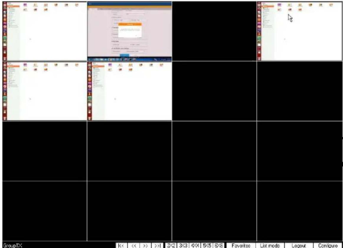
| No. | Item Description | |
| 1 | Next Arrow Use these two | buttons to navigate to the next page or to the end of the list if there are more Channels available than can be seen on the page. |
| 2 | Previous Arrow | Use these two buttons to navigate to the previous page or to the beginning of the list if there are more Channels available than can be seen on the page. |
| 3 | Grid Selection Select a range for how many Channels you want to display. Options are: 2x2, 3x3, 4x4, 5x5, and 6x6. | |
| 4 | Favorites Click Favorites | to list only the Channels marked as favorites. Click All to list all Channels.To add/remove a Favorite, go to List Mode, select a Channel and then right click with the mouse to select Add to Favorite or Remove from Favorite. |
| 5 | List Mode Click to view the | Channel connections in a list that can be sorted by name or with favorites listed first. Click the Channel Name heading to change the sort. List Mode is discussed on page 149. |
| 6 | Logout Click this button to | log out of the Connection Page. |
| 10 | Configure Click this button | to return to the main OSD screen. |
Profile Page
Click the Profile Page tab and the following screen appears:
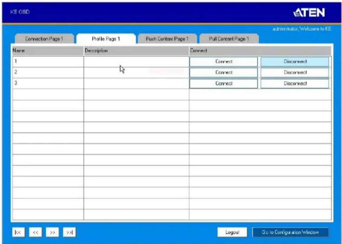
The Profile Page components are described in the table below:
| No. | Item Description | |
| 1 | Name Lists the Profiles | available. Profiles give Receivers access to Channels and allow you to push the connection. |
| 2 | Description The field provides a description of the Profile that was entered when it was created. | |
| 3 | Connect Click Connect and the Receiver will connect with the settings of that Profile (see Adding a Profile, page 220). | |
| 4 | Disconnect Click Disconnect to end the current Profile connection. | |
| 5 | Next Arrow Use these two buttons to navigate to the next page or to the end of the list if there are more Profiles available than can be seen on the page. | |
| 6 | Previous Arrow Use these two buttons to navigate to the previous page or to the beginning of the list if there are more Profiles available than can be seen on the page. | |
| 7 | Logout Click this button to log out of the Connection Page. | |
| 8 | Go to Configuration Window | Click this button to return to the main OSD screen. |
Push Content
Push Content allows you to push the Receiver's computer connection to another Receiver's console, allowing both to access to the computer. Select the Push Content tab and the following screen appears:
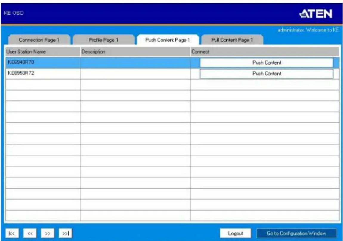
The Push Content Page components are described in the table, below:
| No. | Item Description | |
| 1 Receiver Name Lists the Receivers that can be selected to push the local Receiver's computer connection to. | ||
| 2 Description The field provides a description of the Receiver that was entered when it was created. | ||
| 3 Connect Click Push Content to push the local Receiver's computer connection to the selected Receiver's console. The local Receiver's computer connection will appear on the Receiver that it was pushed to and both will share access to the computer. The access mode selected at the local Receiver will determine how access is shared (see Transmitter Permissions, page 197 for details). | ||
| 5 Next Arrow Use these two buttons to navigate to the next page or to the end of the list if there are more choices available than can be seen on the page. | ||
| 6 | Previous Arrow Use these two | buttons to navigate to the previous page or to the beginning of the list if there are more choices available than can be seen on the page. |
| 9 | Logout Click this button to log | out of the Connection Page. |
| 10 | Go to Configuration Window | Click this button to return to the main OSD screen. |
Pull Content
Pull Content allows you to pull a Receiver's computer connection to the local Receiver's console, allowing both to access to the computer. Click the Pull Content tab and the following screen appears:
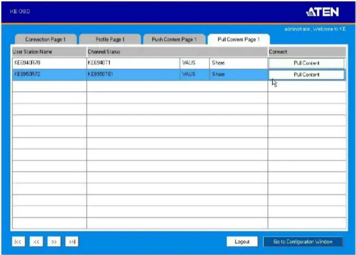
The Pull Content Page components are described in the table, below:
| No. | Item Description | |
| 1 | Receiver Name Lists the Receiver names currently connected to the Channel listed under Channel Status. | |
| 2 | Channel Status Lists the name, description and access type of each available Channel connection. | |
| 3 | Connect Click Pull Content and the Receiver will pull the Channel connection to the local console using the access mode displayed under Channel Status. | |
| 5 | Next Arrow Use these two buttons to navigate to the next page or to the end of the list if there are more choices available than can be seen on the page. | |
| 6 | Previous Arrow Use these two buttons to navigate to the previous page or to the beginning of the list if there are more choices available than can be seen on the page. | |
| 9 | Logout Click this button to log out of the Connection Page. | |
| 10 | Go to Configuration Window | Click this button to return to the main OSD screen. |
This Page Intentionally Left Blank
Overview
The CCKM KE Matrix Manager Software is a browser based GUI that provides management of KE Series devices over a network. You can download the KE Matrix Manager Software for free and manage up to 8 KE devices, or purchase a full version of the KE Matrix Manager Software. To purchase the full version, contact your local authorized ATEN dealer. To download the free KE Matrix Manager Software, use the instructions below.
Download - Trial Version
To download the KE Matrix Manager software, do the following:
- Visit our website and click Support & Downloads → ESERVICE.

- Under Account, click Create New or Log In.
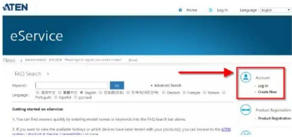
- After logging in, click Product Registration to register the KE device(s) you have purchased.
![ATEN Home Sign Out Language 1: English eService News [External Issue] 2023-09-25 Please log to require your product today? [Main] Welcome Brett Open Case > If the support is that does not show up it might be already closed, please click on "Advance eSupport Search" to increase the old cases. Type Last Quality Date Status Account - Log In - Create New Product Registration - Product Registration Support - FAQ Search - ATEN Hotkey / Product & Device Compatibility List - Download Center - Ask a Question - Trouble Shooting](/content/2026/05/1059622/images/e69e871ba5435cdff4a434773b7c80fdb1f535cfc6c97607fb621fb27a584c45.jpg)
- After you have registered the KE device(s), click Trial Software Download.

| Serial Number | Model | Date of Purchase | Invoice / Shipping Document | Warranty Due Date | Action |
| 12345678901235 | KE6940 | 2015/10/20 |
Note: The trial version of the KE Matrix Manager software includes full functions to set up and configure up to 8 KE Series devices. The KE Matrix Manager trial version will never expire. If you would like to purchase the official full version of the KE Matrix Manager software, please contact your ATEN reseller and see page 164.
- Click the software version you would like to download, then click Save.
My Download >
| FAQ Attachment Download Trial Software Download | ||
| File Title | Web Site | File Download |
| CCKM V2.0.193 (Linux version) | CCKM Trial link V2.0.193 (click download icon to download CCKM Linux version) | |
| CCKMV2.0.193 (Windows version) | CCKM Trial link V2.0.193 (click download icon to download CCKM Windows version) | |
-
Unzip the cckm_win_Vx.x.xxx.zip or cckm_linux_Vx.x.xxx.zip file and double click the *.exe file to start the installation.
-
Follow the instructions on the next page to install the trial version of the software.
KE Matrix Manager Software Install
The following are instructions to install the full version of the KE Matrix Manager software on a primary or secondary computer. For software requirements, see Minimum Hardware/Software Requirements, page 7.
- Insert the USB license key into a USB port on your computer.
Note: If you have more than 8 KE Series devices in your setup, a second USB license key is required to install KE Matrix Manager on a secondary computer.
- Double click the KEMatrixManagerSetup file to start the setup. When the Introduction screen appears, click Next.
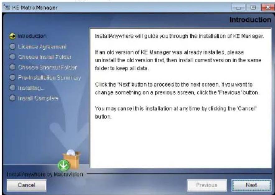
- The License Agreement appears:
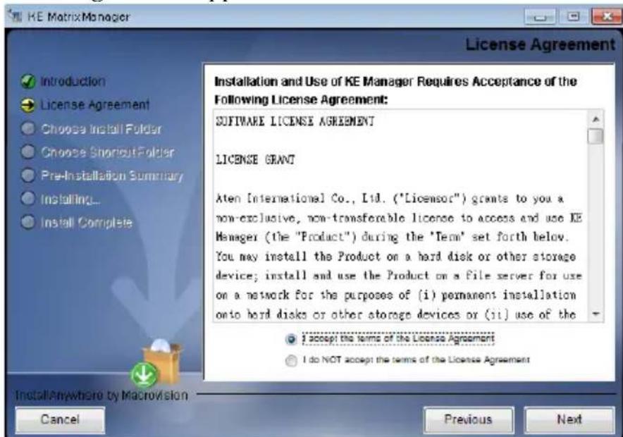
If you agree with the License Agreement, select I accept the terms of the license agreement, and click Next.
- The Choose Install Folder screen appears:
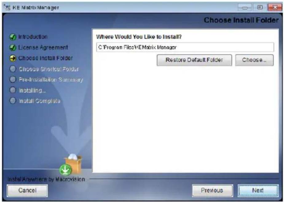
Select where you would like to install the program, and click Next.
- The Choose Shortcut Folder screen appears:
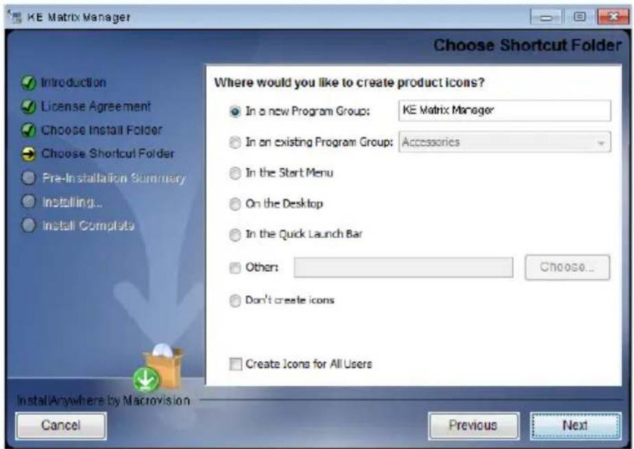
Select where to create shortcuts for the program by selecting the options provided, and click Next.
- The Pre-Installation Summary screen appears:

Confirm the settings you've selected. If you want to make a change click Previous to go back, or click Install to begin the software installation.
- When the process is done, the Install Complete screen appears:
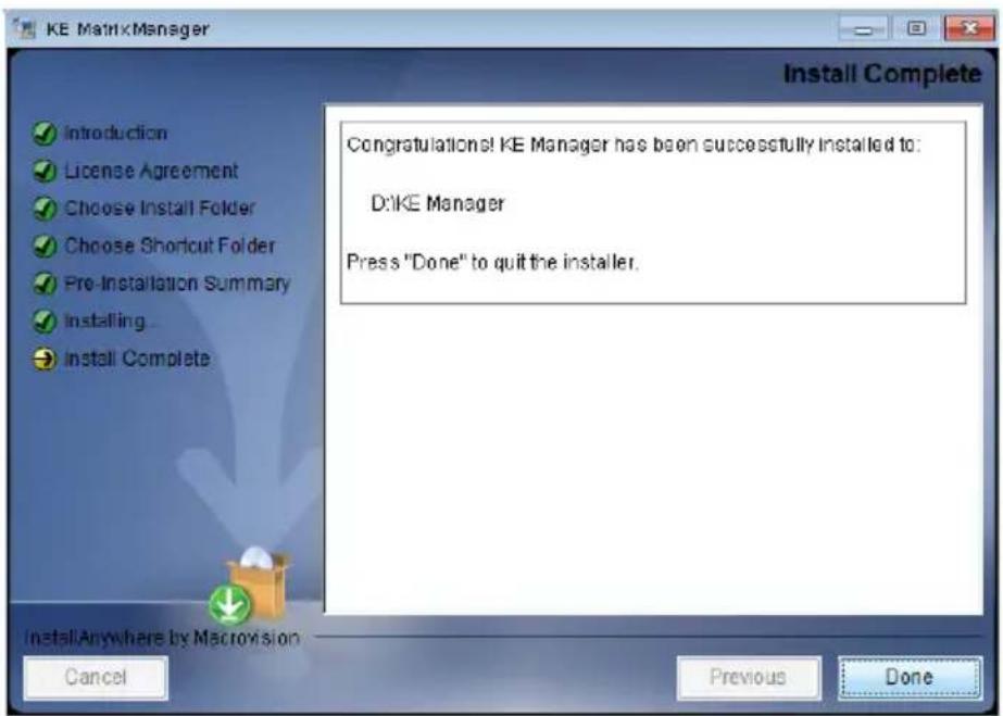
Click Done.
Upgrading Trial Version
After you purchase a license to upgrade the KE Matrix Manager trial version to the full version of the KE Matrix Manager software, go to the Settings - General tab (see page 225), and at the top page, select Click to Upgrade:
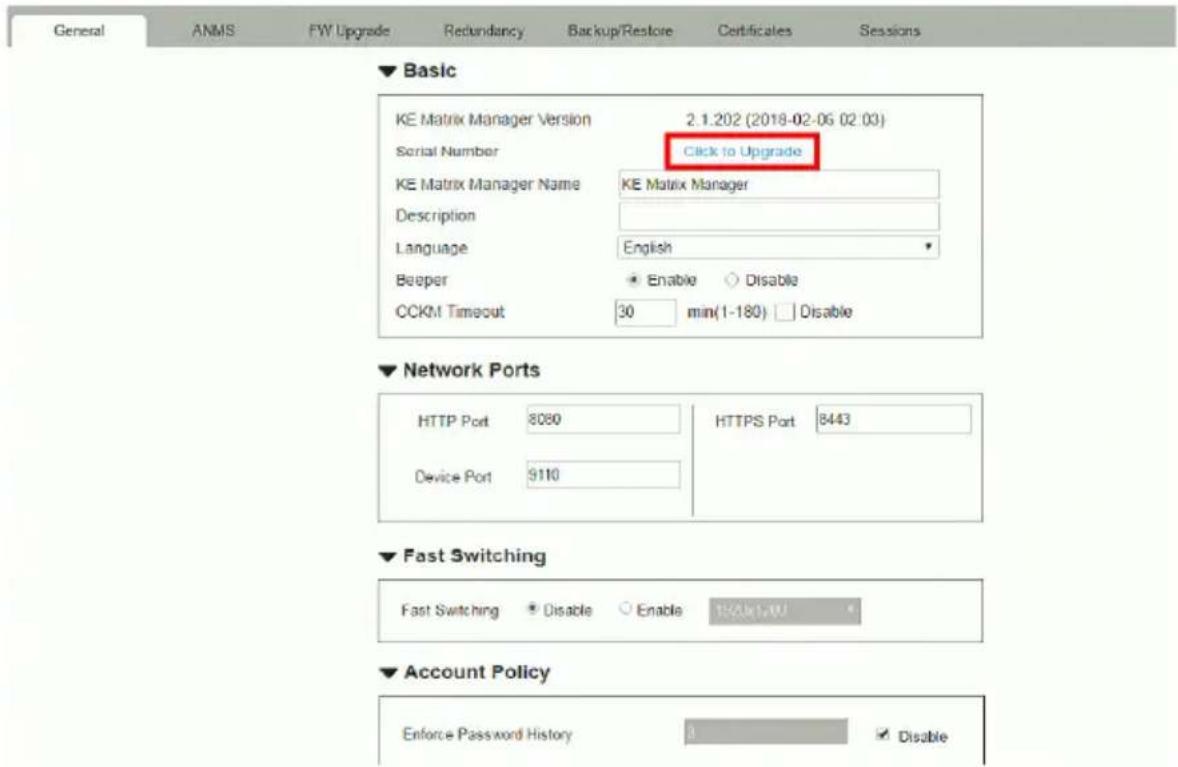
Linux Installation
The following are instructions to install the full version of the KE Matrix Manager software on a Linux server. For software requirements, see Minimum Hardware/Software Requirements, page 7.
- Download the KE Matrix Manager installation file to the Linux server.
- Change the properties of the installation file so that its executable by running the command: chmod a+x filename
Example: chmod a+x kemanager_setup.bin
- Start the installation with the command:
sudo sh ./kemanager_setup.bin
- When the Introduction screen appears, click Next.:
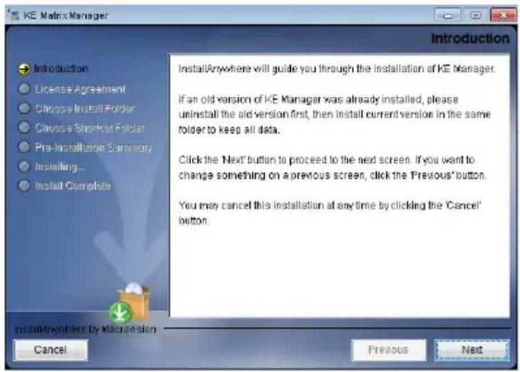
- The License Agreement appears:
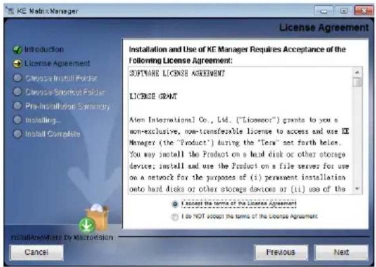
If you agree with the License Agreement, select I accept the terms of the license agreement, and click Next.
-
When the Choose Install Folder screen appears, select the location and continue through the installation by clicking Next.
-
After the software installs successfully, a directory provides useful links:
mitch@mitch-945GCM-S2L:/$ sudo -i
[sudo] password for mitch:
root@mitch-945GCM-S2L:~# ls -al
total 40
drwx---- 7 root root 4096 +二 14 13:42 .
drwxr-xr-x 25 root root 4096 +二 14 10:04 ..
-rw---- 1 root root 65 +二 14 13:42 .bash_history
-rw-r--r-- 1 root root 3106 + 23 2015 .bashrc
drwx---- 2 root root 4096 七 20 04:49 .cache
drwx---- 3 root root 4096 +二 13 16:07 .gnupg
drwxrwxr-x 4 root root 4096 +二 14 13:29 .java
drwxrwxr-x 5 root root 4096 +二 14 13:39 KeManager
drwxrwxr-x 2 root root 4096 +二 14 09:58 .oracle_jre_usage
-rw-r--r-- 1 root root 148 八 17 2015 .profile
root@mitch-945GCM-S2L:~# cd KeManager/
root@mitch-945GCM-S2L:~/KeManager# ls
kemanager Query_Service Uninstall_Matrix_Manager
_kemanager_installation Service_Manager
root@mitch-945GCM-S2L:~/KeManager#
- The "Uninstall_Matrix_Manager" can be used to uninstall the software. By default the root folder can be accessed as shown below:
sudo -i cd /root cd KeManager sudo ./Uninstall_Matrix_Manager
- To check and stop the KE Matrix Manager service, use the following commands:
cd KeManager sudo ./Query_Service Stop service: sudo ./Stop_Service
![root@mtch-945GCM-S2L:-/KeManager# sudo ./Query_Service java version "1.8.0_121" Java(TM) SE Runtime Environment (build 1.8.0_121-b13) Java HotSpot(TM) 64-Bit Server VM (build 25.121-b13, mixed node) VAJSW: yajsw-stable-11.04 OS : Linux/4.4.0-92-generic/amd64 JVM : Oracle Corporation/1.8.0_121 Sep 07, 2017 2:13:51 PM org.apache.commons.vfs2.VfsLog info INFO: Using "/tmp/vfs_cache" as temporary files store. Sep 07, 2017 2:13:52 PM org.rzo.yajsw.os.posix.PosixService init INFO: /etc/init.d/jkemaker-service already exists Sep 07, 2017 2:13:52 PM org.rzo.yajsw.os.posix.PosixService getpid INFO: wrapper pid file: /run/wrapper.kenanager-service.pid Name : kenanager-service Installed : true Running : false Interactive : false Automatic : false Manual : false Disabled : false Paused : false Unknown : false Press [Enter] ... root@mtch-945GCM-S2L:-/KeManager# cd Service Manager/ root@mtch-945GCM-S2L:-/KeManager/Service_Manager# ls Install Service Start Service Stop Service Uninstall Service root@mtch-945GCM-S2L:-/KeManager/Service_Manager# sudo ./Stop_Service java version "1.8.0_121" Java(TM) SE Runtime Environment (build 1.8.0_121-b13) Java HotSpot(TM) 64-Bit Server VM (build 25.121-b13, mixed node) java version "1.8.0_121" Java(TM) SE Runtime Environment (build 1.8.0_121-b13) Java HotSpot(TM) 64-Bit Server VM (build 25.121-b13, mixed node) VAJSW: yajsw-stable-11.04 OS : Linux/4.4.0-92-generic/amd64 JVM: Oracle Corporation/1.8.0_121 Sep 07, 2017 2:15:01 PM org.apache.commons.vfs2.VfsLog info INFO: Using "/tmp/vfs_cache" as temporary files store. Sep 07, 2017 2:15:02 PM org.rzo.yajsw.os.posix.PosixService init INFO: /etc/init.d/jkemaker-service already exists ********** STOPPING kenanager-service ********** Sep 07, 2017 2:15:04 PM org.rzo.yajsw.os.posix.PosixService stop INFO: Stopping kenanager-service ... VAJSW: yajsw-stable-11.04 OS : Linux/4.4.0-92-generic/amd64 JVM : Oracle Corporation/1.8.0_121 ********** STOPPING kenanager-service ********** Service kenanager-service stopped](/content/2026/05/1059622/images/a58be0b6b85b63b67249f22635af615530e56c5b19c8b024f8d437ab1c60e932.jpg)
- To check and start the KE Matrix Manager service, use the following commands:
cd KeManager sudo ./Query Service Stop service: sudo ./Start service
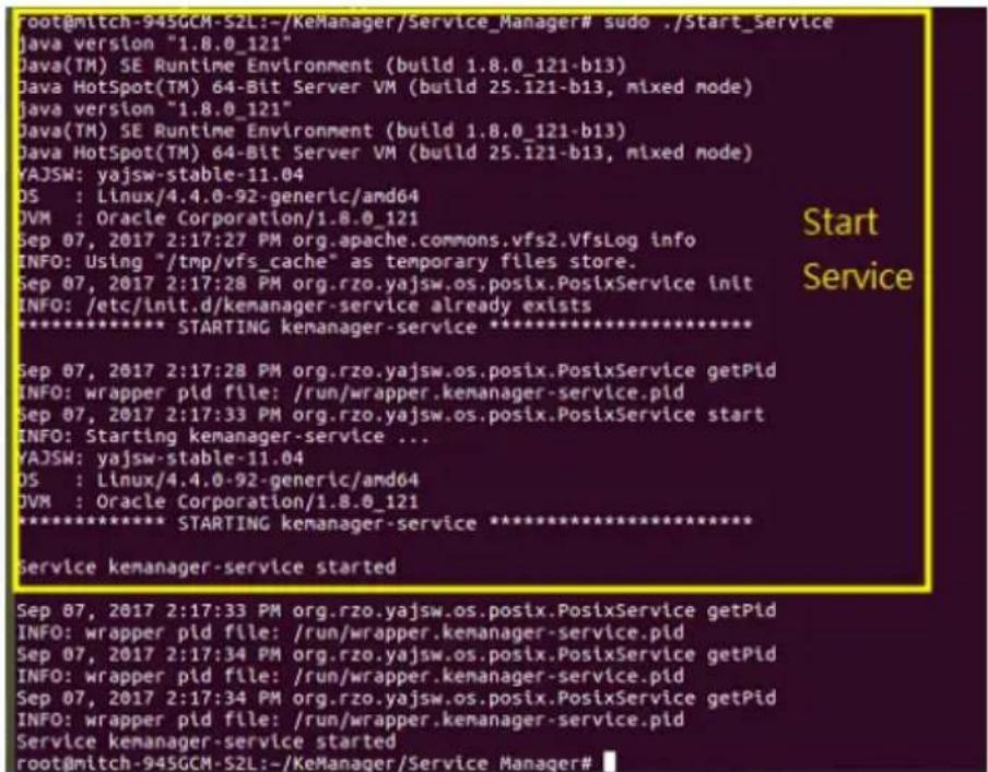
This Page Intentionally Left Blank
Overview
The CCKM KE Matrix Manager Software can be accessed through most standard web browsers and via Telnet. Once users log in and are authenticated, the browser GUI comes up. The first section explains the login procedure and web browser components. The last section provides details for connecting via Telnet.
Logging In
To log into the KE Matrix Manager, do the following:
- Open the browser and specify the IP address of the computer installed with the KE Matrix Manager software, in the browser's URL location bar.
Note: If the administrator has configured the HTTP or HTTPS port setting as something other than the default, you must include http://or https://before the IP address, and specify the port number along with the IP address. For example:
https://192.168.1.20:8443
Where 8443 is the https port number, or 8080 is the http port number, and a colon is inserted between it and the IP address.
- If a Security Alert box appears, accept the certificate – it can be trusted (See Trusted Certificates, page 327 for details). The Login page appears:

- Enter the Username and Password, and click Login.
Note: Only administrator accounts can be used to login. By default, the username and password are administrator and password, respectively.
- For security purposes, the system will prompt you to change the password immediately.
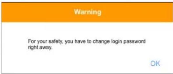
Click OK for the password change dialog box.
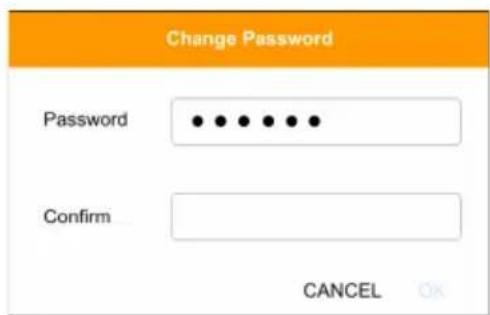
- Enter the new password and confirm it by entering the password again.
- Click OK to complete the change and the KE matrix manager main page appears. Refer to the next page for more details.
The KE Matrix Manager Main Page
After you have successfully logged in, the web browser's main page appears:
![ATEN CCKM KE Matrix Manager Welcome to the KE Matrix Manager System Status Transmitter Active Standby Offline Total Receiver 0 3 0 3 0 3 ... ... Users Profile Log Online Idie Total Next Scheduled to net Warning Error Information 1 2 1 None 0 0 4 ... ... Redundancy Status: [Standover] [List] Connections TX RX RX TX Transmitter Receiver Units Scheduled Profile Go to Schedule Instant Link Copyright © 2018 ATEN International Co., Ltd](/content/2026/05/1059622/images/fc6b6f494f461e7d0e5b9d89c3a19a842165dbbd856153750d10e91bed907414.jpg)
Web Components
The web components are described in the table below:
| No. | Item Description | |
| 1 | Install Wizard This icon helps | you locate Transmitters/Receivers on the LAN to add them to the KE Matrix Manager (see Installation Wizard, page 173). If a device can't be found, check the Network settings in the device's OSD menu (see page 132 & 140). |
| 2 | System Settings | Click this icon to enter the System Setting section where you can configure the KE Matrix Manager software. The Settings are discussed on page 225. |
| 3 | Logout Click this button to log | out of your KE Matrix Manager web session. |
| 4 | Interactive Display Panel This | is your main work area. Scroll the page up or down to view the various selections. Some items can be clicked to open a settings page, while others provide status information. |
| 5 | Instant Link Clicking this icon | opens the lower bar which allows you to instantly connect KE devices. Instant Link is discussed on page 176. |
Interactive Display Panel
The functions associated with each of the icons on the main Interactive Display Panel are explained in the table below:
| Icon Function | |
 | System Status: System Status provides an overview of the transmitter, receiver, user, profile, and log status. Each heading can be clicked to open the respective settings page. System Status is discussed on page 183. |
 | Connections: Connections provides a visual display of current transmitter and receiver connections. Connections is discussed on page 247. |
 | Scheduled Profile: Scheduled Profile provides an overview of connection profiles that are scheduled to run. Scheduled Profile is discussed on page 251. |
 | Sessions: Sessions provides a list of current user sessions. Sessions is discussed on page 253. |
 | Refresh: The Refresh button provides a way to update the information currently being displayed on the page. |
 | To Top: This button appears at the bottom right corner of the Interactive Display Panel and allows you to jump back to the top of the page. |
Installation Wizard
Use the Install Wizard to add Transmitters and Receivers to the CCKM. The wizard locates devices on the network and walks you through adding them. To add devices, do the following:
- Connect all Transmitters and Receivers to the LAN.
- On the CCKM main page, click the Install Wizard icon (page 171).
- When the installation wizard appears, select options to locate devices:
![Install Wizard 1. Connect all Transmitters and Receivers to the local area network. Search Local Search Subnet Transmitter 2 [1]00-10-74-A9-01-12 [2]00-10-74-A9-00-00 Receiver 2 [1]00-10-74-A8-00-00 [2]00-10-74-A8-01-03 CANCEL NEXT](/content/2026/05/1059622/images/a0434fc35293561423317219233bff4e3e7f99d449b3bdd1b675106296bde08c.jpg)
| Item Description | |
| Search Local | Check this box and click the Refresh button to search the local area network for Transmitters/Receivers. |
| Search Subnet Check this box, enter a subnet IP and then click the Refresh button to search the subnet for Transmitters/Receivers. | |
| Transmitter / Receiver | Displays the number of Transmitters and Receivers that have been discovered on the network. Use the check boxes next to the Transmitters/Receivers to select the devices you want to add. |
 | The Refresh button provides a way to update the information currently being displayed in the install wizard window. |
- Check the boxes under Transmitter / Receiver to select the devices you want to add, then click Next.
(Continues on next page.)
- Under Assign IP Address select an option to configure the network settings, then click Next.
Install Wizard
2. Assign IP Address.
Transmitter
2
Receiver
2
IP Range
Transmitter


Receiver


DHCP
Use Original IP Setting
BACK
NEXT
| Item Description | |
| IP Range | Select the IP Range radio button to enter a series of static IP addresses to assign to the Transmitters/ Receivers that you are adding. |
| DHCP | Select the DHCP radio button for dynamic IP address assignment. |
| Use Original IP Setting Select this radio button to use the IP address currently configured on the Transmitter/Receiver. | |
- Use the Naming Rule radio button to create a naming convention (Title + Number); or Use Original Name to use the name currently configured on the Transmitter/Receiver, then click Next.
Install Wizard
3. Rename devices automatically.

Naming Rule
Transmitter
Title
+ Number start from

Receiver
Title
+ Number start from


Use Original Name
BACK
NEXT
- Confirm each Transmitter's Name, IP Address, Audio setting and check the boxes to set Permissions*, then click Next and repeat the process for Receivers.
Install Wizard
4. Confirm Transmitter information.
Permissions ☑ View Only ☑ Occupy ☑ Exclusive
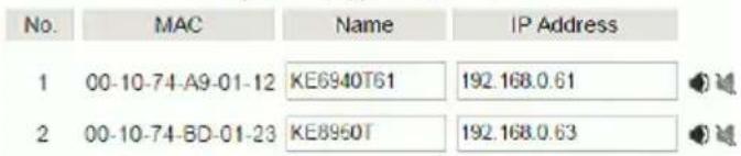
BACK NEXT
Note: See Transmitter Permissions, page 197, and Receiver Permissions, page 210 for information about setting permissions.
- Click Done.
Instant Link
At the bottom of the KE Matrix Manager Main Page is the Instant Link bar. In this section you can quickly connect Receivers to Transmitters.
The top panel provides the Receiver List, and the bottom panel provides the Transmitter List. To create a connection, click a Receiver in the top panel and use the drop-down menu to select a Transmitter (as shown in the image below); or drag-and-drop Transmitters from the bottom panel to Receivers in the top panel. Configure as many Receiver to Transmitter connections as needed, and then click Apply.
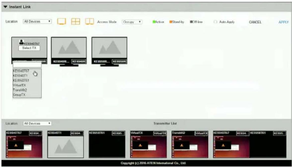
| Item Description | |
| Instant Link The Instant Link | bar provides access to quickly connect Receivers to Transmitters. Click the bar to open the panel, click again to minimize the panel. The top panel provides a list of all the Receivers discovered on the LAN.Click a Receiver and use the drop-down menu to select a Transmitter. |
| Transmitter List Click the Tr | transmitter List bar to open the panel. The panel provides a list of all the Transmitters discovered on the LAN. Drag-and-drop Transmitters in the bottom panel to Receivers in the top panel to establish the connection. |
| Location Use the drop-down | menu to select a location to filter the Receivers or Transmitters displayed on the page. |
 | Click this icon to show individual Receivers. |
 | Click this icon to show only video wall Receivers. |
 | Click this icon to show only Receiver Group Receivers. |
| Access Mode Click a device | and use the drop-down box to set the access mode: Occupy, View Only, or Exclusive. |
| Auto Apply Checking this box | allows you to drag and drop devices and apply the connection immediately without having to click the Apply button. |
| Apply Click Apply to connect the devices. | |
| Cancel Click Cancel to exit without connecting. | |
RS-232 / Telnet
The KE Series can be operated and configured via a remote terminal session using Telnet. This is a useful means for configuring devices when they are first setup and connected to the network.
Telnet
To log into the KE Series device by means of a Telnet session, do the following:
- On your computer, open a terminal (command line) session.
- At the prompt, key in the KE device's IP address with port 23 in the following way:
telnet [IP address] [port]
- Please press "Enter" to start "TextMenu" The login screen appears. At the login prompt, provide the Password.
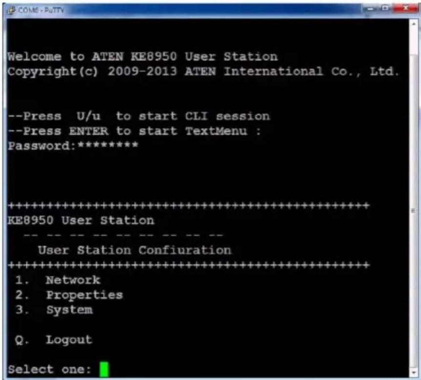
Note: The default password for Telnet sessions is password.
RS-232
To log into the KE Series device by means of a RS-232 session, do the following:
- The controller's serial port should be configured the same as the Receiver's default configuration, as shown below:
| Baud Rate 9600 | |
| Data Bits 8 | |
| Parity None | |
| Stop Bits 1 | |
| Flow Control None | |
The Receiver's Function Switch should be set to RS-232 Config (see page 40). Before executing RS-232 commands across a network you must install the KE Matrix Manager software on a computer and ensure that it is online. For the Slim Version of KE Series (KE8900ST/8900SR/9900ST). Please make sure the RS-232 Serial Port is not connected before executing commands.
- Please press "Enter" to start "TextMenu" The login screen appears. At the login prompt, provide the Password.
Note: The default password for Telnet sessions is password.
Configuration Menu
Once a Telnet connection to the KE device is established, the device's text-based Configuration Menu comes up, allowing you to select options by entering a number on the following screens:
Main Menu
KE6900 Receiver
Receiver Configuration
- Network
- Properties
- System
Q. Logout
Select one:
1. Network
KE6900 Receiver
Network Settings
- IP Installer [Enabled]
- DHCP [Disabled]
- IP Address [172.17.17.34]
- Subnet Mask [255.255.255.0]
- Default Gateway [172.17.17.254]
Q. Exit
Select one:
2. Properties
KE6900 Receiver
Device Properties
- Mode [Matrix]
- Transmitter Video IP Address [172.17.17.35]
- Transmitter Audio IP Address [172.17.17.35]
- Transmitter USB IP Address [172.17.17.35]
- Transmitter RS232 IP Address [172.17.17.35]
- UART Configuration
- Video [Enabled]
- Audio [Enabled]
- USB [Enabled]
10.RS232 [Enabled] - KE Matrix Manager IP [172.17.17.33]
- KE Matrix Manager Port [9110]
- Beeper [Enabled]
- USB Mode [VM]
- USB Secure Transmit [Disabled]
Q. Exit
Select one:
3. System
KE6900 Receiver
System Setting
-
Device Name [KE6900R]
-
Device Description [Receiver1]
Device IP Address: 172.17.17.34
Device MAC Address: 00:10:74:A8:01:23
Device FW Version: V1.1.109
Device Serial Number:
-
Password [Enabled]
-
Change Password
-
System Reboot/Reset to Factory Default
Q. Exit
Select one:
Note: The Reset to Factory Default function resets everything but the login information to the factory default settings. To reset the login information, refer to Reset All Information on page 329.
Chapter 6
System Status
Overview
The System Status panel is found at the top of the KE Matrix Manager Main Page. This section provides status information about Transmitters, Receivers, Users, Profiles and Logs. Click on a selection to open a Settings page, which are discussed in the sections that follow.
![CCKM KE Matrix Manager Welcome to the KE Matrix Manager System Status Transmitter Active Stand-by Off-line Total 0 3 0 3 ... Receiver Active Stand-by Off-line Total 0 3 0 3 ... Users Profile Log On-line Idle Total Next schedule 2days I... 1 4 3 Profile2 ... Warning Error Information ... ... Redundancy Status: [Primary] [Working] Connections TX-RX RX-TX Receiver Transmitter Unit KE10050N72 KE0040T67 administrator (share) Instant Link Copyright (c) 2010 ATEN International Co., Ltd.](/content/2026/05/1059622/images/9afe8f040d17fa7efa40257e6c0cb09fbe623ea743dfd2e1534518822d4a4bc3.jpg)
System Status
The System Status panel has five sections that provide information and a link to each settings page. Each settings page can be accessed by Clicking within the section: Transmitter, Receiver, Users, Profile or Log. Each section is explained in the table below and the Settings on the pages that follow.

System Status

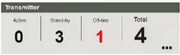
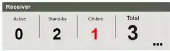
Redundancy Status: [Primary] [Working]
| Item Description | |
| Transmitter This section provides an overview of the Transmitters added to the KE Matrix Manager:Active: Shows the number of Transmitters that are currently online and connected to a Receiver.Standby: Shows the number of Transmitters that are online but not connected to a Receiver Offline: Shows the number of Transmitters added to the KE Matrix Manager that are not online.Total: Displays the total number of Transmitters added to the KE Matrix Manager. | |
| Receiver This section provides an overview of the Receivers added to the KE Matrix Manager:Active: Shows the number of Receivers that are currently online and connected to a Transmitter.Standby: Shows the number of Receivers that are online but not connected to a Transmitter Offline: Shows the number of Receivers added to the KE Matrix Manager that are not online.Total: Displays the total number of Receivers added to the KE Matrix Manager. | |
| Users This section provides | an overview of users with KEMatrix Manager sessions:◆ On-line: Shows the number of users that are logged into OSD or KE Matrix Manager web sessions.◆ Idle: Shows the number of users not logged into OSD or KE Matrix Manager web sessions. |
| Profile This section provides | an overview of Profile and Profile Schedules:◆ Total: Shows the total number of Profiles available.◆ Next scheduled to run: Shows the name of the next Profile scheduled to run.◆ Days later: Shows the number of days until the next Profile is scheduled to run. |
| Log This section provides an overview of system logs:◆ Warning: Shows the number of warnings logs generated since the event log was cleared.◆ Error: Shows the number of error logs generated since the event log was cleared.◆ Information: Shows the number of information logs generated since the log was cleared. | |
| Redundancy Status | This section provides information about the Redundancy mode. The first set of brackets shows which server is hosting the KE Matrix Manager database: [Primary] or [Secondary]. If Redundancy is disabled the first bracket will read: [Standalone]. The second set of brackets show the status:◆ [Working]: The server is actively hosting the KE Matrix Manager database.◆ [Standby]: This message appears when database operations are idle. |
Transmitter
Click Transmitter in the System Status panel to open the settings. On this page you can add, delete and configure Transmitters (physical transmitters), Virtual Transmitters (multi-source) and Transmitter Groups (multi-video source). The KE Matrix Manager automatically adds Transmitters connected to the local area network with a valid IP address.
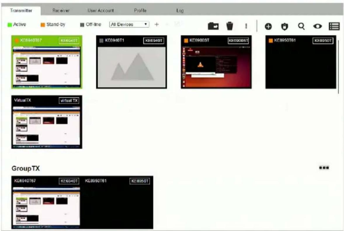
The meanings of the icons and headings on the page are straightforward and let you view and configure Transmitters.
Active refers to a Transmitter connection that is online and in use.
Standby refers to a Transmitter connection that is online.
- Offline refers to a Transmitter connection that is offline.
- All Devices ▼ Use this drop-down menu to filter Transmitters by location. Use Locations to limit the Transmitters seen on the page.
-
- Click to add a new Location.
- Select a Transmitter and click the Move to icon to add devices to a Location.
- ✗ Select a Location from the drop-down menu and click this icon to delete it.
- Select a Location and click this icon to change the name.
Click to delete selected Transmitters.
Click an option to have selected Transmitters:
- Copy & Paste: Copy settings from one Transmitter and paste them to another (see Copy & Paste, page 193).
- Beeper: Sound a Beep.
- Reboot: Shut down and restart.
- Reset to Factory: Reset all setting to the factory default.
Note: The Reset to Factory function resets everything but the login information to the factory default settings. To reset the login information, refer to Reset All Information on page 329.
-
- Click to Create Virtual TX or Create TX Group (page 194 & 196).
- Click to set Transmitter permissions (page 197).
- Click to search for Transmitters.
- Click to filter Transmitters shown on the page.
Click to switch between Grid View and List View.
Transmitter Configuration
When the KE Matrix Manager discovers Transmitters on the network they appear on the Transmitter settings page. Double-click a Transmitter to configure its settings.
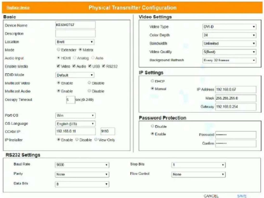
| Item Description |
| Basic Device Name: Enter a name for the Transmitter. |
| Description: Enter a description for the Transmitter. |
| Location: Use the drop-down menu to select a Location for the device. Locations filter the Transmitters seen on the settings page. |
| Mode: Use the radio button to select how the Transmitter will be installed and managed: |
| Select Extender mode for simple one-to-one (Transmitter to Receiver) setups that are managed at the Receiver's OSD menu. |
| Select Matrix mode to manage devices and connections over the LAN from the KE Matrix Manager software. This mode is for advanced administration of Transmitter and Receiver connections configured within the KE Matrix Manager Web GUI. |
| Enable Media: Select which source type the Transmitter can stream: Video, Audio, USB and RS232. |
| Audio Input: Use this option to select the Transmitter's audio source signal: HDMI, Analog, or Auto. This setting should reflect the audio setting configured on the computer.* |
| Note: The Audio Input option is only available on KE devices with HDMI capabilities. |
| Item Description | ||
| Basic | EDID Mode: EDID contains a display's basic information and is used by the source device to utilize the best resolution across different monitors. WhenManualorRemixis selected, the Receiver's OSD will have a button allowing the local EDID setting to be configured for the connection (seeEDID Mode, page 150). Select how you want the source device to acquire the display's EDID:Default: EDID is set to the default ATEN configuration. This setting must be used when connecting KE6900 devices to KE8950 devices.Auto: Checks the EDID of all connected displays and the ATEN default EDID to use the best common resolution for all displays.Manual: Manually set the EDID configuration from the Receiver's OSD (seeEDID Mode, page 150).Remix: Manually checks the EDID of all connected displays and the ATEN default EDID to use the best common resolution for all displays (seeEDID Mode, page 150).Multicast Video: SelectEnableto allow a broadcast of the Transmitter's video signal to be sent to multiple Receivers.Multicast Audio: SelectEnableto allow a broadcast of the Transmitter's audio signal to be sent to multiple Receivers.Occupy Timeout: Set a time threshold for Receivers whose Access Mode has been set to Occupy If there is no activity from the Receiver occupying the port for the amount of time set here, the Receiver is timed out and the port is released. The first Receiver to send keyboard or mouse input after the port has been released gets to occupy the port. Input a value from 1 to 240 seconds.Port OS: Use the drop-down menu to select the operating system on the computer connected to the Transmitter.OS Language: Use the drop-down menu to select the operating system language on the computer connected to the Transmitter.CCKM IP: Set theIPaddress andPortnumber of the computer running the KE Matrix Manager software. The default port number is 9110.IP Installer: The IP Installer is an external Windows-based utility for assigning an IP address to the device. Click a radio button to select Enable, Disable or View Only for the IP Installer utility. SeeIP Installer, page 326 for instructions. | |
| Video Settings These refer to the Transmitter's video settings: | ||
| Video Type: Select the DVI video connector being used by the display: Digital (DVI-D) or Digital (DVI-I). This option is only available for KE6900 units. | ||
| Color Depth: Select the number of bits to use for the color depth: 24, 16, or 8. This is the number of bits used to describe the color of a single pixel. A bit depth determines the number of colors that can be displayed at one time. | ||
| Bandwidth Limit: Select the maximum bandwidth that the Transmitter can use to transmit video over the network. A lower bandwidth transmits lower quality video; a higher bandwidth sends higher quality video but this can affect network speed. | ||
| Video Quality: Select the video quality to use. 5 is the highest video quality, and 1 is the lowest video quality. Options are: 1~5. | ||
| Background Refresh: Sets how often the Transmitter refreshes the background image on the connected display. Options are to refresh every 256,128, 64, 32,16, or 0 frames. | ||
| IP Settings | For dynamic IP address assignment, select the DHCP radio button. To specify a fixed IP Address, Subnet Mask, and Default Gateway select the Manual radio button and fill in the fields with values appropriate for your network. For information to configure the network settings locally on the device, see Network Configuration, page 125. | |
| Password Protection | Select Enable to require a password to access the Transmitter's OSD configuration screens (see page 130). Enter a Password, and confirm the password in the Confirm box. | |
| RS232 Settings Configure the serial device settings for the Transmitter. The default settings are: | ||
| Baud Rate: 9600 | ||
| Parity: None | ||
| Data Bits: 8 bits | ||
| Stop bits: 1 bit | ||
| Flow Control: None | ||
| Item Description | |
| Replace Device | Click Replace Device in the top left corner to replace an old Transmitter with a new one.* All settings are copied from the old Transmitter to the new Transmitter. Before using this feature, connect the new Transmitter to the network. After clicking Replace Device, use the drop-down menu to select the new Transmitter where the settings will be applied.Note:1. This option only appears when a Transmitter is offline.2. This feature can be used for both Receivers and Transmitters. Replacement should be carried out on a similar model. |
| Save Click Save to | save changes to the properties. |
| Cancel Click Cancel | to exit without saving. |
Copy & Paste
Copy & Paste allows you to copy settings from one Transmitter and paste them to another. To copy Transmitter settings to another device, do the following:
- Select a Physical Transmitter.
- On the Transmitter menu bar, click Copy & Paste (page 187).
- Check the boxes of the settings you want to copy, and click Next.
Copy & Paste
1. Please select the items you want to copy.
Select All
□ Basic
□ Description
□ Location
□ Mode
□ Enable Media
□ EDIO Mode
□ Multicast Video
□ Multicast Audio
□ Occupy Timeout
Port OS
OS Language
□ CCKM IP
□ IP Installer
Unselect All
RS232 Settings
□ Baud Rate
□ Parity
□ Data Bits
□ Stop Bits
Flow Control
□ Video Settings
□ Video Type
□ Color Depth
Bandwidth
□ Video Quality
Background Refresh
CANCEL
NEXT
- Select the Transmitter(s) where you want to apply the settings, and click Done.
Copy & Paste
2. Please select the targets you want to paste.
SelectAll
KE6940T62
KE8950T
Unselect All
PREVIOUS
DONE
Virtual Transmitter
Creating a Virtual Transmitter allows you to create one connection that sources media (KVM, audio, USB, serial) from different Transmitters. Virtual Transmitters appear on the Transmitter settings page with Virtual TX in the top right corner. Simply select an online Transmitter for each media source. Dual Display Transmitters can be added as two separate Virtual Transmitters.
To create a Virtual Transmitter, in Transmitter settings click + and then select Create Virtual TX.
Create Virtual TX
Name
VirtualTX
Description
Location
Unallocated

KVM
Select Device

Audio
Select Device

USB
Select Device

Serial
Select Device

CANCEL
APPLY
| Item Description | |
| Name Enter a name for the Virtual Transmitter. | |
| Description Enter a description for the Virtual Transmitter. | |
| Location Use | the drop-down menu to select a location for the Virtual Transmitter or leave it Unallocated. See Location, page 186, for details. |
| KVM Use the | drop-down menu to select a KVM (keyboard, video, mouse) source for the Virtual Transmitter. |
| Audio Use the | drop-down menu to select an audio source for the Virtual Transmitter. |
| USB Use the | drop-down menu to select a USB source for the Virtual Transmitter. |
| Serial Use the | drop-down menu to select a serial source for the Virtual Transmitter. |
| Apply Click Apply to save the changes. | |
| Cancel Click Cancel to exit without saving. | |
Intelligent Dual Video Output Management
For the A models (KE6900A, KE6940A), the Intelligent Dual Video Output Management feature allows the separation of a Dual Display Transmitter's (KE6940AT) video outputs (DVI:1 and DVI:2) as two separate Virtual Transmitters. These separated outputs can be accessed from different Receivers (KE6900AR or KE6940AR). Receivers can switch between and connect to both Virtual Transmitters independently with the Access Type determining which Receiver has control (see page 197).
To use this setup, install the KE devices as shown below and create two Virtual Transmitters, selecting DVI:1 and DVI:2 as the KVM source for each Virtual Transmitter.
For non-A model receivers (e.g. KE6910R, KE6912R), you can select between DVI:1 or DVI:2, but you will always be getting video output from DVI:1.
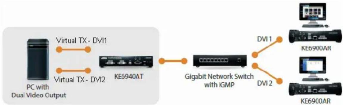
flowchart
graph LR
    A["PC with Dual Video Output"] -->|Virtual TX - DVI1| B["KE6940AT"]
    A -->|Virtual TX - DVI2| B
    B --> C["Gigabit Network Switch with IGMP"]
    C -->|DVI1| D["KE6900AR"]
    C -->|DVI2| E["KE6900AR"]
When connecting to either of the two Virtual Transmitters in the setup shown above, the mouse cursor may reside on the main or extended dual display screen, out of view. Therefore even if you have control of the mouse it may not be visible. To bring the mouse cursor into view on either of the dual display screens, first enable Boundless Switching (see Boundless Switching, page 209) and then use the hotkey F8+F9.
Transmitter Group
Creating a Transmitter Group allows you to create a connection that sources the video from multiple Transmitters to view at across multiple Receiver displays. To use this feature, connect a Transmitter Group to a Receiver Group (page 206). Transmitter Groups appear at the bottom of the Transmitter settings page.
To create a Transmitter Group, in Transmitter settings click + and then select Create TX Group.
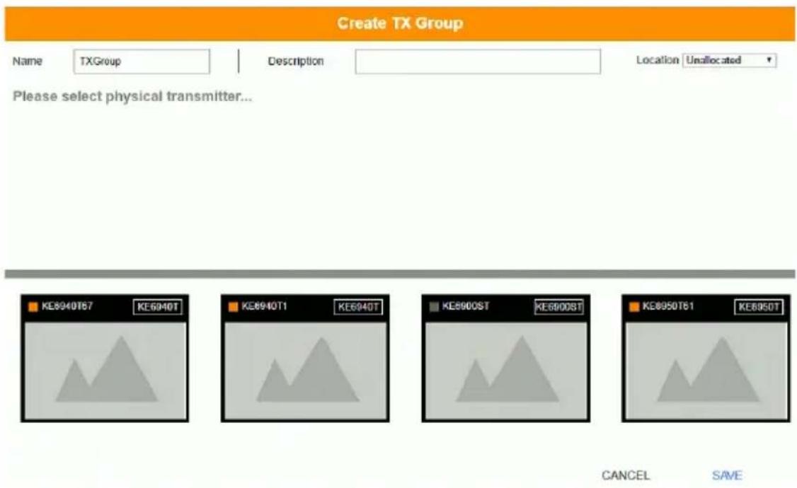
Fill in the appropriate information and then double-click or drag-and-drop Transmitters to add or remove them in the top panel. The Transmitters in the top panel will be used as the video source for the Receiver Group at the Receiver.
| Item Description | |
| Name Enter a name for the | Transmitter Group. |
| Description Enter a description | on for the Transmitter Group. |
| Location Use the drop-down | menu to select a location for theTransmitter Group or leave it Unallocated. See Location,page 186, for details. |
| Save Click Save to save the | changes. |
| Cancel Click Cancel to exit | without saving. |
| Note: You can create up to 4 transmitter groups. | |
Transmitter Permissions
Transmitter Permissions sets the users and groups that can access a Transmitter, Virtual Transmitter, and Transmitter Group.
Select a device under Transmitter List, and then next to each user or group click All, View, Occupy, or Exclusive to grant them permission to connect to the Transmitter with this access type. A green block denotes that the user has access.
To set Transmitter Permissions, in Transmitter settings, click
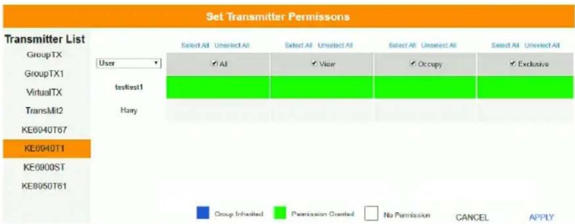
| Item Description | |
| Transmitter List | Lists Transmitters, Virtual Transmitters and Transmitter Groups that can be selected to set permissions. |
| Drop-Down Menu | Use the drop-down menu to selectUser or Group. After making a selection, the list of users or groups appears. Set permissions by selecting the access type (All, View, Occupy, Exclusive) next to each user or group. |
| Access Type Select the access you want to grant to a user or group by clicking under the heading(s). This defines how the Transmitter can be accessed by a user or group. The access type will appear available for the user in the Receiver's OSD Connections menu. To disable an access type, uncheck a box in the heading.All: User has full control and can simultaneously share control of the Transmitter. Input from the users is placed in a queue and executed chronologically.View: User can only view the remote screen, and cannot perform operations on it.Occupy: The first user to access the Transmitter has control. However, additional users may view the Transmitter's video. If the user who controls the Transmitter is inactive for longer than the time set in the Transmitter's Timeout box, control is transferred to the first user to move the mouse or strike the keyboard. | |
| Access Type | Exclusive: The first user to access the Transmitter has exclusive control over the Transmitter. No other users can view the Transmitter. The Timeout function does not apply when Transmitters are accessed with this setting. |
| Apply Click Apply to save the changes. | |
| Cancel Click Cancel to exit without saving. | |
Receiver
Click Receiver in the System Status panel to open the settings. The Receiver page allows you to add, delete and configure Receivers (physical receivers), Receiver Groups, and Video Walls. The KE Matrix Manager automatically adds Receivers connected to the local area network with a valid IP address.
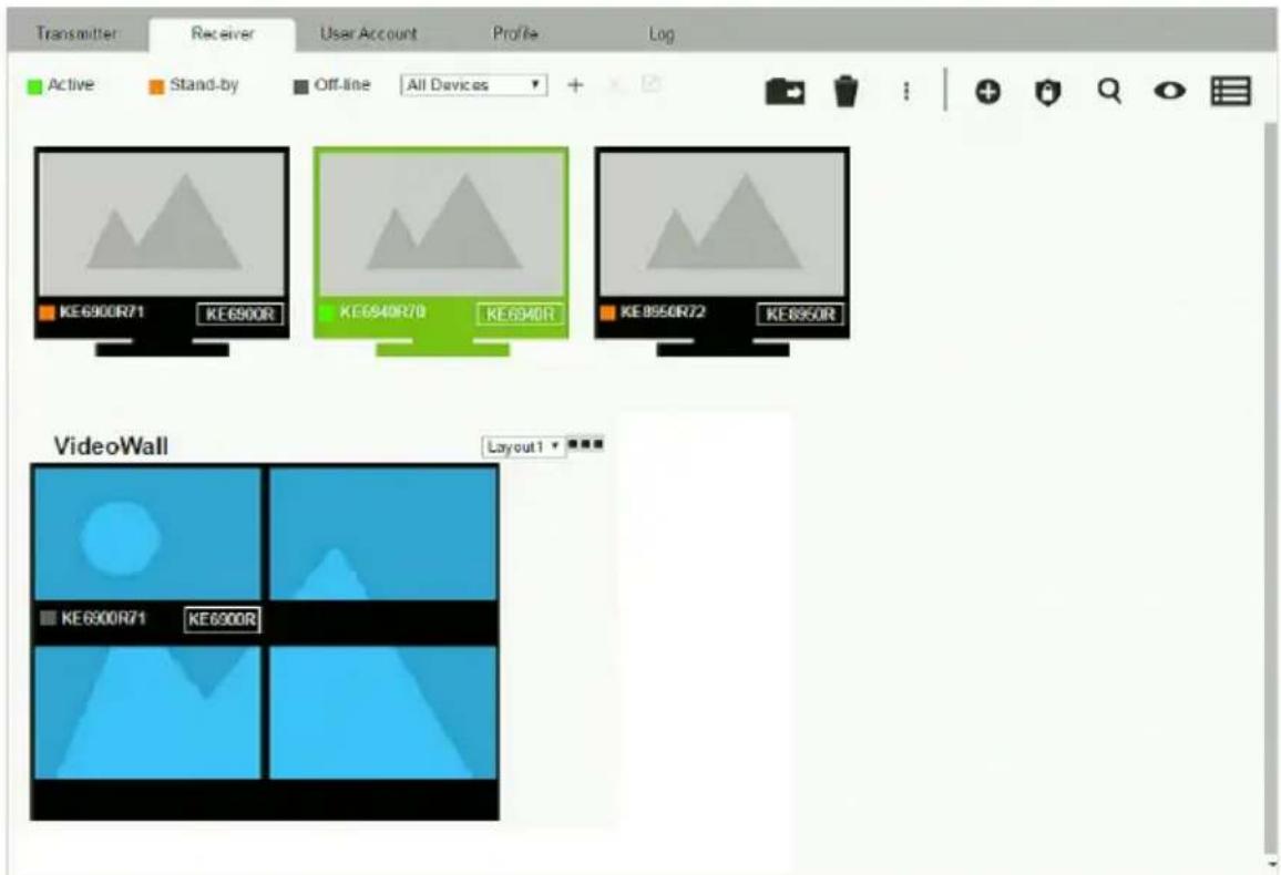
The meanings of the icons and headings on the page are straightforward and let you view and configure Receivers.
Active refers to a Receiver connection that is online and in use.
Standby refers to a Receiver connection that is online.
- Offline refers to a Receiver connection that is offline.
- All Devices ▼ Use this drop-down menu to filter Receivers by location. Use Locations to limit the Receivers seen on the page.
-
- Click to add a new Location.
- Select a Receiver and click the Move to icon to add devices to a Location.
- ✗ Select a Location from the drop-down menu and click this icon to delete it.
Select a Location and click this icon to change the name.
Click to delete selected Receivers.
Click an option to have selected Receivers:
- Copy & Paste: Copy settings from one Receiver and paste them to another (see Copy & Paste, page 205).
- Beeper: Sound a Beep.
- Reboot: Shut down and restart.
- Reset to Factory: Reset all setting to the factory default.
Note: The Reset to Factory function resets everything but the login information to the factory default settings. To reset the login information, refer to Reset All Information on page 329.
-
- Click to Create Receiver Group or Video Wall (page 206 & 207).
- Click to set Receiver permissions (page 210).
- Click to search for Receivers.
- Click to filter Receivers shown on the page.
Click to switch between Grid View and List View.
Receiver Configuration
When the KE Matrix Manager discovers Receivers on the network they appear on the Receiver settings page. Double-click a Transmitter to configure its settings.
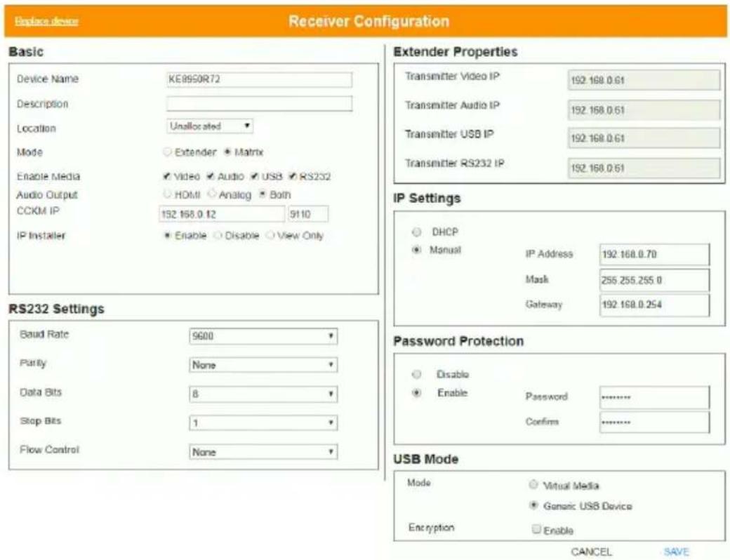
| Item Description | |
| Basic Device Name: Enter a name for the Receiver. | |
| Item Description | |
| IP Settings | For dynamic IP address assignment, select the DHCP radio button.To specify a fixed IP Address, Subnet Mask, and Default Gateway select the Manual radio button and fill in the fields with values appropriate for your network.For information to configure the network settings locally on the device, see Network Configuration, page 125. |
| Password Protection | Select Enable to require a password to access the Receiver's OSD configuration screen (see page 130).Enter a Password, and confirm the password in the Confirm box. |
| USB Mode Select | the type of USB device you will connect to the USB ports:Virtual Media: Select this option only if you are plugging a USB disk drive (including USB HDD/optical disk) into the USB ports.This will give you the highest data transfer speeds but will not allow other USB devices to work when plugged into the USB ports. When Receivers connected to the same transmitter mount or unmount USB disk drives, the keyboard and mouse operations will experience a brief delay. Transmitters can support up to 12 virtual media connections at the same time (keyboard/mouse included).vUSB (Generic USB device): Use this option to plug USB peripherals* into the USB ports. This option also allows a keyboard and mouse with special functions to plug into the USB ports for console use. Use this only if the special functions of the keyboard or mouse are required but do not work when plugged into the console ports. When the keyboard and mouse are plugged into the USB ports, they will not work within the OSD menus. To work within the OSD menus, the keyboard and mouse must be plugged into the console ports. KE6900ST/KE8900ST/KE9900ST transmitters do not support the Generic USB Device mode. In this mode, KE6900/KE6940 transmitters supports up to 2 USB connections; and KE8950/KE8952 transmitters support up to 5 USB connections (keyboard/mouse excluded).Encryption: Check this box to encrypt USB disk drives plugged into the USB ports.Note: This USB port does not support isochronous endpoints, therefore USB peripherals that stream audio or video data, such as speakers or webcams, will not work. |
| Replace Device | Click Replace Device in the top left corner to replace an old Receiver with a new one.* All settings are copied from the old Receiver to the new Receiver. Before using this feature, connect the new Receiver to the network. After clicking Replace Device, use the drop-down menu to select the new Receiver where the settings will be applied.Note:1. This option only appears when a Transmitter is offline.2. This feature can be used for both Receivers and Transmitters. Replacement should be carried out on a similar model. |
| Save Click Save to | save changes to the properties. |
| Cancel Click Cancel | to exit without saving. |
Copy & Paste
Copy & Paste allows you to copy settings from one Receiver and paste them to another. To copy Receiver settings to another device, do the following:
- Select a Physical Receiver.
- On the Receiver menu bar, click Copy & Paste (page 200).
- Check the boxes of the settings you want to copy, and click Next.
Copy & Paste
1. Please select the items you want to copy.
Select All
Unselect All
□ Basic
□ Description
□ Location
□ Mode
□ Enable Media
□ CCKMIP
IP Installer
□ USB Mode
□ Mode
□ Encryption
□ RS232 Settings
□ Baud Rate
□ Parity
□ Data Bits
□ Stop Bits
□ Flow Control
□ Extender Properties
☐ Transmitter Video IP
Transmitter Audio IP
☐ Transmitter USB IP
☐ Transmitter RS232 IP
CANCEL
NEXT
- Select the Receiver(s) where you want to apply the settings, and click Done.
Copy & Paste
- Please select the targets you want to paste.
SelectAll
Unselect All
KE6940R62
KE8950R94
PREVIOUS
DONE
Receiver Group
Creating a Receiver Group allows you to connect the video from multiple transmitters to multiple Receiver displays. To use this feature, connect a Transmitter Group (page 196) to a Receiver Group (see Instant Link, page 176). Receiver Groups appear at the bottom of the Receiver settings page.
To create a Receiver Group, in Receiver settings, click + and then select Create RX Group.
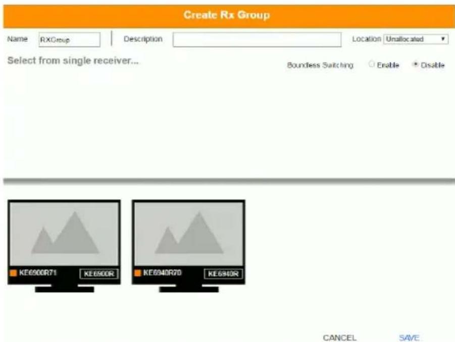
Fill in the appropriate information and then double-click or drag-and-drop Receivers to add or remove them in the top panel. The Receivers in the top panel will be used to view the video from the Transmitter Group. To connect a Transmitter Group to a Receiver Group, see Instant Link, page 176.
| Item Description | |
| Name Enter a name for the Receiver Group. | |
| Description Enter a description for the Receiver Group. | |
| Location Use the drop-down menu to select a location for the Receiver Group or leave it Unallocated. See Location, page 186, for details. | |
| Boundless Switching | Use the radio button to enable or disable Boundless Switching. See Boundless Switching, page 209 for details. |
| Save Click Save to save the changes. | |
| Cancel Click Cancel to exit without saving. | |
Note: You can create up to 4 receiver groups.
Video Wall
Creating a Video Wall allows you to create connections that combine Receiver displays to form a large video wall. Use the options to group multiple Receivers in the video wall. A video wall can contain multiple forms of single displays and grouped displays in various layouts. Video Walls appear listed below Receivers, on the Receivers settings page.
To create a Video Wall, in Receiver settings, click + and then select Create Video Wall.
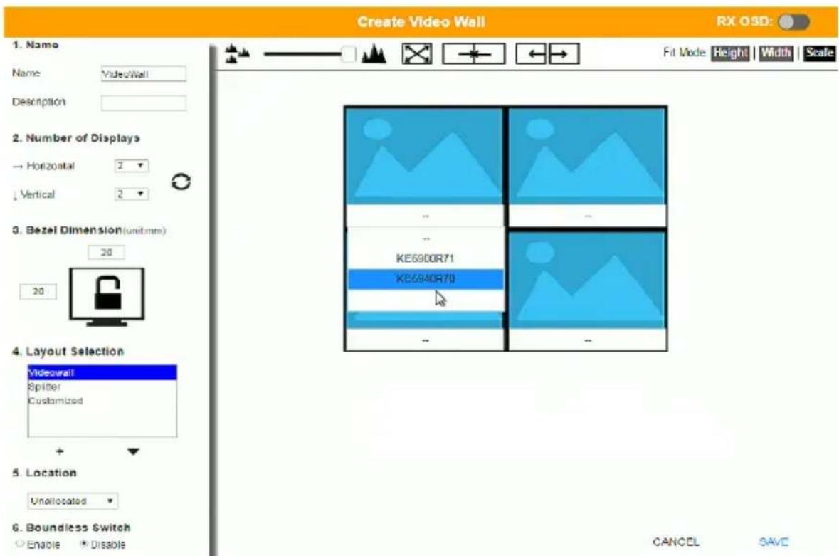
Select the number of displays and then group multiple displays to form large screens and/or use single displays for independent screens to create the video wall's layout. Click the bar -- under the display icon to select a Receiver for each display. This configuration should match the actual video wall layout.
| Item Description | |
| Name Enter a name for the Video Wall. | |
| Description Enter a description for the Video Wall. | |
| Number of Displays Use the Horizontal and Vertical drop-down menus to select the number of displays that make up the video wall (a maximum of 64 are supported). Match this to the physical layout of the displays. Click the refresh icon to update the layout. | |
Bezel Dimension Use the  | two boxes to increase/decrease the frame size of each active display. |
| Lock / Unlock | Click the monitor toLockthe (2) bezel settings, so that when one size is changed they all change.Click the monitor toUnlockthe (2) bezel settings, so that each size can be set independently. |
| Layout Selection | Click + orXto add or remove additional layouts to the Video Wall. The options listed here will appear in a drop-down menu for the Video Wall, allowing you to quickly choose different layouts from the Receiver settings page. Arrows below the Layout Selection box allow you to move up or down in the list.Three layout templates are available for quick setup. The Videowall and Splitter options can not be changed but allow you to select the Receivers. These three layouts can not be deleted.◆Video Wallprovides a basic full screen layout where one Transmitter connects to multiple Receivers to display the video together as one full screen.◆Splitterprovides a layout that connects a Transmitter to multiple Receivers that show the same video displayed on separate screens independently.◆Customizedprovides a basic full screen layout that can be configured into groups (seeGroupbelow) as desired.*Note:When using the KE6940R inCustomized layouts, only the KE6940's first video port will display video because each port's video source is independent. When using the KE6940R inVideo Wallor Splitter layouts both video ports will display video. |
| Location Use the drop-down | menu to select a location for the Video Wall or leave it Unallocated. SeeLocation, page 186, for details. |
| Item Description | |
| Boundless Switching Enable this feature to allow you to switch KVM control between different receivers by moving the mouse cursor across screen boundaries. This option is disabled by default.When Boundless Switching is enabled, make sure to disable the following settings:On the computer, under Control Panel - Mouse Properties - Pointer Options, uncheckEnhance pointer precision.On the CCKM Main page, click Settings (page 225), then on the General tab scroll down and disableFast Switching.Note:Dual Display Transmitters can be set up as two independent Virtual Transmitters with Boundless Switching. The placement of the KE6940 setup must have DVI-1 as the main display on the left and DVI-2 as a secondary display on the right.Boundless Switching only supports single or dual video outputs from any one computer.If the mouse cursor disappears under a Linux operating system, execute this command:gsettings set org.gnome.setting-daemon.plugins.cursor active false | |
 | Use the slide bar to zoom in or out for a better view of the Video Wall layout. |
 | Click this icon to reset the zoom back to full size. |
 | Select multiple display icons and click theGroupbutton to group the displays into one screen. |
 | Select a group and clickUngroupto ungroup the displays. |
| Fit Mode Select how the video wall will be displayed:Height:Fits the video to the height of the display.Width:Fits the video to the width of the display.Scale:Fits the video on the entire display. | |
 | Use theRX OSDbutton to enable/disable showing the Receiver's name and IP address in the top left corner of the connected display. This helps identify which Receiver is connected to the display. |
| Save Click Save to save the changes. | |
| Cancel Click Cancel to exit without saving. | |
Receiver Permissions
Receiver Permissions sets which users and groups can access a Receiver. Select a device under the Receiver List, and then click under Operation to grant a user or group permission to access the device. This will allow the user to login to the Receiver's OSD menu to access the Connections tab.
To set Receiver Permissions, in Receiver settings, click

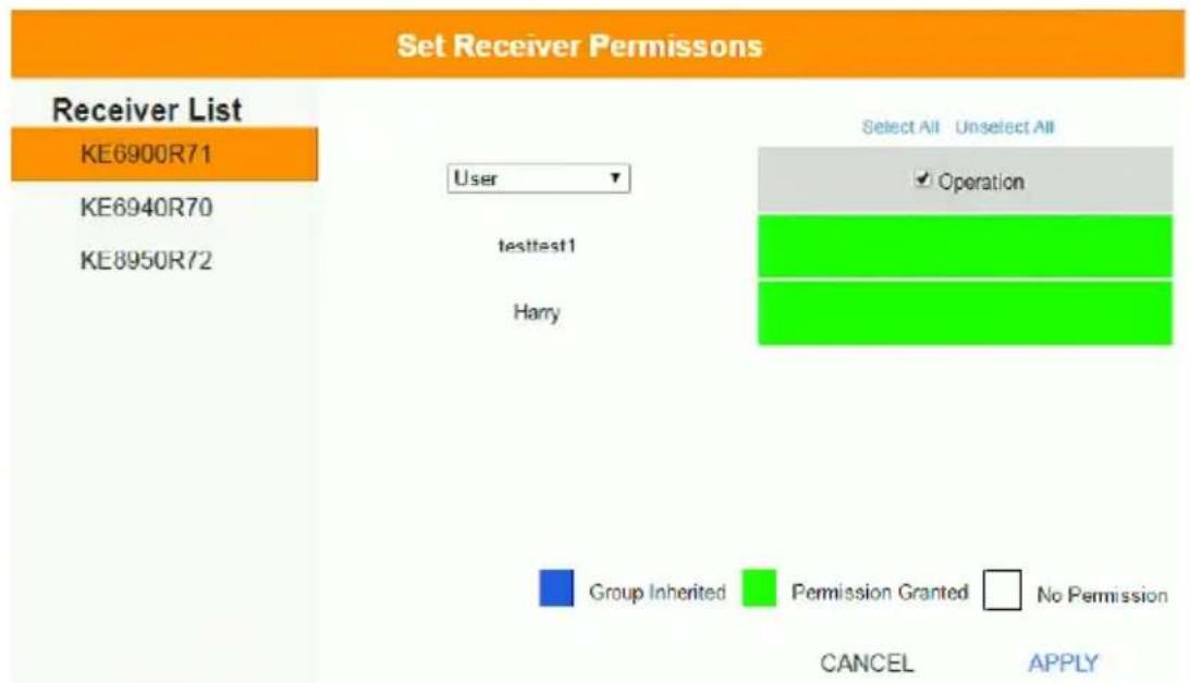
| Item Description | |
| Receiver List Lists the Receivers which can be selected to set permissions. | |
| Drop-Down Menu | Use the drop-down menu to selectUser or Group. After making a selection, the list of users or groups appears. Set permissions by selecting the Operation box next to each user or group. |
| Operation Click the Operation | box next to each user or group to apply access rights on the selected device. This gives users and groups permission to log in to the Receiver's OSD. If a user inherits its permissions from a group, the box will be Blue. To disable access rights for all users, uncheck the box in the heading. |
| Apply ClickApplyto save the changes. | |
| Cancel Click Cancelto exit without saving. | |
Account
Click Users in the System Status panel to open the settings. The Account page allows you to add, delete and configure users and groups. Instructions for adding users and groups is provide on page 212.
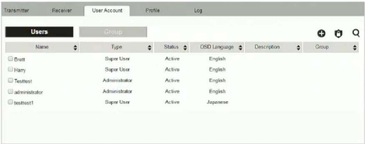
- The Users and Group buttons appear at the top of the page.
- Depending on the item selected, either Users or Groups are listed on the page.
- The sort order of the information displayed can be changed by clicking the column headings.
- Three icons in the right corner are used to add users, groups and set permissions, as explained in the sections that follow.
Users
The KE Matrix Manager supports three types of accounts, shown in the table below:
| User Type Role | |
| Administrator Access, push/pull and management of the KE Matrix Manager, including configuration and setting up of devices. Manage Users, Groups, Transmitters, Receivers, Profiles and Video Walls. Configure personal working environments. | |
| Super User Access and push/pull Receivers, Transmitters and Profiles they have been given permission for. | |
| User Access Receivers to connect to Transmitters they have been given permission for. | |
Adding Users
To add a user, do the following:
- Click on the menu bar.
- Select Add New User. The Add New User window opens:
![Add New User Username Password Confirm Password Description User Level Administrator Super User Users Status Active Disable OSD Language English Toolbar Hotkey [Scroll Lock][Scroll Lo Logout Timeout 30 min(1-180) Screen Blanker 30 min(1-30) OSD Title Bar Duration 30 sec(3-100) Welcome Message Enable Username Group Select CANCEL SAVE](/content/2026/05/1059622/images/fe5fd4b0b51913e1fa5fc3ab118c8d4bb7873c05d792c0e2202730b507c7ceb1.jpg)
Enter the required information in the fields provided. A description of each is given in the table below:
| Field Description | |
| Username From 1 to 3 | 2 characters are allowed depending on the Account Policy settings. |
| Local User | Check the Local User box if the account is for logging in to the KE Matrix Manager software or a Receiver.Uncheck the Local User box if the account is authenticated with a 3rd party external source, such as RADIUS, LDAP/AD, or TACACS+. See ANMS, page 231 for details. |
| Password From 6 to 3 | 2 characters are allowed depending on the Account Policy settings. |
| Confirm Password To | be sure there is no mistake in the password, you are asked to enter it again. The two entries must match. |
| Description Additional | information about the user that you may wish to include. |
| User Level There are | three account categories: Administrator, Super User and User.The Administrators have full access to make changes within the KE Matrix Manager software, which includes adding and removing Transmitters, Receivers, accounts, preferences, and configuration settings.The Super Users have access to the Receiver's OSD menu and can connect Channels and Profiles.The Users can log in to Receivers to connect channels. |
| Status | Status allows you to control the user's account and access, as follows:Active provides the user with access and permissions as granted.Disable lets you suspend a user's account without actually deleting it, so that it can be easily reinstated in the future. |
| OSD Language Click | the drop-down menu to select the language you want to use during OSD sessions for this user. Options are: Chinese (Traditional), Simplified Chinese, Japanese, German, Korean, Russian, French, Spanish, and Portuguese. |
| Toolbar Hotkey Select | the hotkey combination to call the Tool Bar function for this user. The Tool Bar is used when accessing the computer from the Transmitter or Receiver side. |
| Logout Timeout If there | is no user input for the amount of time set with this function, the user is automatically logged out. A login is necessary before the KE Matrix Manager can be accessed again. The default is 30 minutes. |
| Screen Blanker Set how | how many minutes the device waits when a session is idle before turning off the display. |
| OSD Title Bar Duration | This function is only supported by KE6910/KE6912.When the accessing a port, the top left-hand corner will show a title bar displaying the access mode and the device name.Select how long you wish the title bar is to be displayed for, or check Disable to not show any title bar. |
| Welcome Message If you want the Welcome Message to appear on screen when the user logs into the KE Matrix Manager, select Enable.If you want the user's Screen Name to appear with the Welcome Message, check the Username check box. | |
| Group Click Select and check a box to add the user to a group. | |
| Apply Click Apply to save the changes. | |
| Cancel Click Cancel to exit without saving. | |
-
When your selections have been made click Apply.
-
When the Operation Succeeded message appears, click OK.
-
The new user appears on the main panel.
- The columns show the Username; User Level, Status, OSD Language, Description; and Group.
Modifying Users
To modify a user, do the following:
- In the main panel, double-click the user's name.
- In the Edit User page that comes up, make your changes, then click Apply.
Deleting Users
To delete a user, do the following:
- In the main panel, check the box next to the user's name.
- Click .
- Click OK.
Groups
Groups allow administrators to easily and efficiently manage users and devices. Since device access rights apply to anyone who is a member of the group, administrators need only set them once for the group, instead of having to set them for each user individually. Multiple groups can be defined to allow some users access to specific devices, while restricting other users from accessing them. Device permissions are discussed on page 217.
Adding Groups
To create a group, do the following:
-
Click Group on the Account page.
-
Click + and then select Add New Group. The Add New Group window opens:
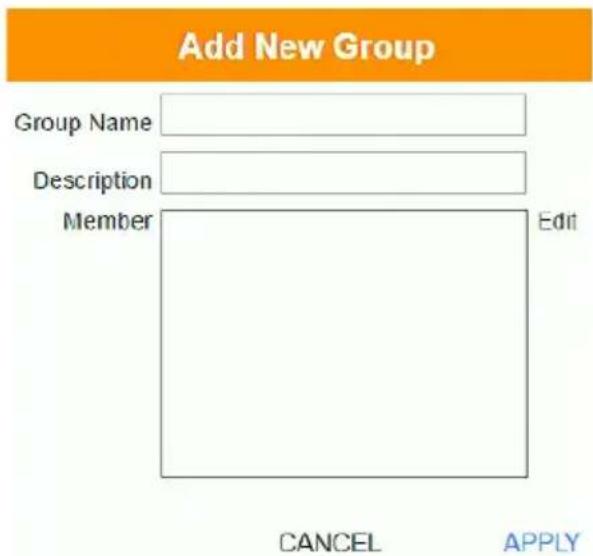
- Enter the required information in the appropriate fields. A description of each of the fields is given in the table below:
| Field Description | |
| Group Name A maximum of | 32 characters is allowed. |
| Description Additional information about the user that you may wish to include. A maximum of 32 characters is allowed. | |
| Member Lists the users that are currently in the group. To add users, click the Edit button. | |
-
At this point you can assign users to the group by clicking Edit.
-
When your selections have been made click Apply.
-
When the Operation Succeeded message appears, click OK.
- The new group appears in the main panel.
- The columns show the Group Name, Description and Members that are in the group.
Repeat the above procedure to add additional groups.
Modifying Groups
To modify a group, do the following:
- In the main panel, double-click the group's name.
- Make your changes, then click Apply.
Deleting Groups
To delete a group, do the following:
- In the main panel, check the box next to the group's name.
- Click .
- Click OK.
Permissions
You can assign Transmitter, Receiver and Profile permissions for users and groups from the Account page.
Assigning Device Permissions
To assign permissions for a user or group from the Account page, do the following:
- Click 🔒 on the menu bar. The Set User Permissions window opens:
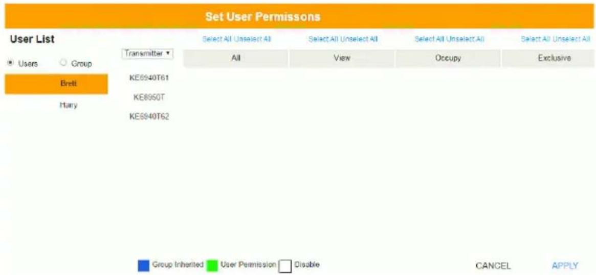
- To set the permissions, select a user or group, then a device and select the Access Type under each column so that it turns green. Make your permission settings for each user or group on each device according to the information provided below:
| Item Description | |
| User List | Use the radio button to view theUsersorGrouplist.Click a user or group to configure their permissions. |
| Drop-Down Menu | Use the drop-down menu to selectTransmitter, Receiver orProfile. After making a selection, a list of devices or profiles appears. Set permissions by selecting the access type (All, View, Occupy, Exclusive) next to the device. |
| Access Type Select the access you want to grant to a user or group by clicking under the heading(s) next to each device. This defines how the device can be accessed by the user or group. When granted, the access types (All, View, Occupy, Exclusive) for Transmitters will appear available for the user in the Receiver's OSD Connection page (see page 148). All:User has full control and can simultaneously share control of the Transmitter. Input from the users is placed in a queue and executed chronologically.View:User can only view the remote screen, and cannot perform operations on it.Occupy:The first user to access the Transmitter has control. However, additional users may view the Transmitter's video. If the user who controls the Transmitter is inactive for longer than the time set in the Transmitter's Timeout box, control is transferred to the first user to move the mouse or strike the keyboard.Exclusive:The first user to access the Transmitter has exclusive control over the Transmitter. No other users can view the Transmitter. The Timeout function does not apply when Transmitters are accessed with this setting.Operation(Receiver and Profile):TheOperationaccess type forReceiversallows users to log into Receivers, and forProfilesallows a user to connect the Profile from a Receiver. | |
| Apply ClickApplyto save the changes. | |
| Cancel Click Cancelto exit without saving. | |
- When you have finished making your choices, click Apply.
- In the confirmation popup that appears, click OK.
Profile
Click Profile in the System Status panel to open the settings. The Profile page allows you to create, run and schedule connection profiles. Profiles channel specific Receiver to Transmitter connections and can be instantly connected from the Profile page at anytime. Profiles can be also scheduled to run automatically at specific times.
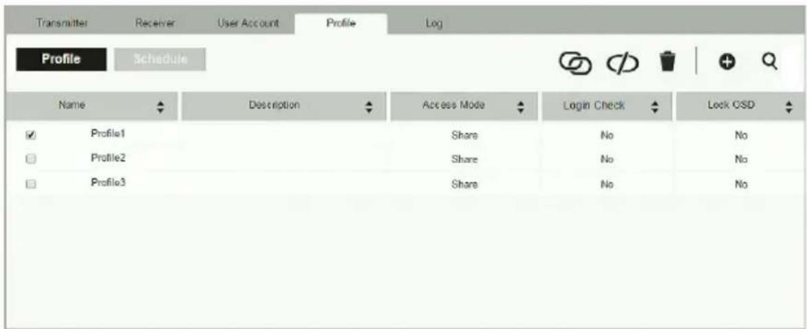
The meanings of the icons and headings on the page are straightforward and let you view and configure Profiles.
Click to connect the selected Profile.
- Click to disconnect the selected Profile.
Click to delete the selected Profile.
- + Click to Create Profile or Create Schedule (page 220 & 223).
Click and enter text to search for a Profile.
Check the box next to a Profile and click the Connect or Disconnect icon to start/stop profile connections. Check the box next to a Schedule and click the Enable or Disable icon to enable/disable a schedule.
- Appears on the Schedule page, click to enable the selected schedule.
- Appears on the Schedule page, click to disable the selected schedule.
Adding a Profile
Creating a Profile allows you to quickly connect single or multiple Receiver to Transmitter connections.
To add a Profile, do the following:
- On the Profile page click + and then select Create Profile. The Create Profile window appears:
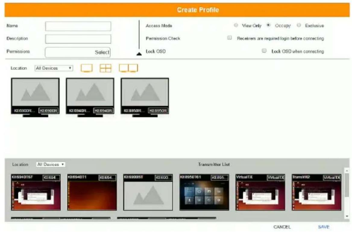
| Item Description | |
| Name Enter a name for the Profile. | |
| Description Enter a description for the Profile. | |
| Permissions | Click Select and check the box of the users / groups you want to allow to connect this Profile. When the user logs into a Receiver, the profile will appear listed in the OSD menu on the Profile page (see page 153), allowing them to connect it. |
| Access Mode This defines how the Transmitter in a Profile can be accessed by Receivers when multiple users attempt to access it.View Only: Receivers only have view access to the Transmitter's video display.Occupy: Set a time threshold for Receivers whose Access Mode has been set to Occupy If there is no activity from the Receiver occupying the port for the amount of time set here, the Receiver is timed out and the port is released. The first Receiver to send keyboard or mouse input after the port has been released gets to occupy the port. Input a value from 1 to 240 seconds.Exclusive: The first Receiver to access the Transmitter has exclusive control over the Transmitter. No other users can view the Transmitter. The Timeout function does not apply to Transmitters which have this setting. | |
| Login Check Check this box | to require a user to be logged in to the Receiver before a Profile can connect it to a Transmitter. When enabled, a user must be logged into the Receiver or it will not connect to the Transmitter when the Profile is initiated. |
| Lock OSD Checking this box | will lock the Receiver's OSD screen when the Profile connects it to a Transmitter. |
| Location Use the drop-down | menu to select a location to filter the Receivers displayed on the page. |
 | Click this icon to show individual Receivers. |
 | Click this icon to show only video wall Receivers. |
 | Click this icon to show only Receiver Group Receivers. |
| Save Click to save the changes. | |
| Cancel Click to exit without saving. | |
-
After filling in the information, click a Receiver, select Select TX and use the drop-down menu select a Transmitter; or use Transmitter List at the bottom of the page to drag-and-drop Transmitters to Receivers to create the connection.
-
After configuring the connections, click Save. The new Profile appears on the Profile page.
-
To connect Profiles, check the box of the Profile(s) you want to connect, and click 📄
- To disconnect Profiles, click .
Adding a Schedule
Creating a Schedule allows you to connect Profiles at specific dates, times and intervals.
To add a Schedule, do the following:
- On the Profile page click
Schedule
- Click + and then select Create Schedule. The Create Schedule window appears:
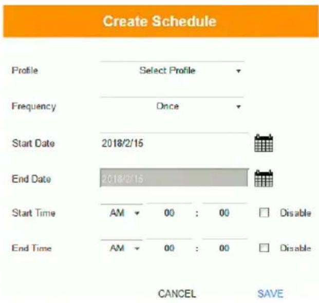
| Item Description | |
| Profile Use the drop-down menu to select a Profile to schedule. | |
| Frequency Use the drop-down menu to select how often the Profile should run: Once, Daily, Weekly and Monthly.When you select Weekly/Monthly an additional drop-down menu appears to select the Week Day/Month Day on which the profile will run. | |
| Start Date Enter the date on which you want the schedule to begin running. | |
| End Date Enter the date on which you want the schedule to stop running. | |
| Start Time Enter the time of day that you want the profile to connect. | |
| End Time Enter the time of day that you want the profile to disconnect. | |
| Every | If you select Daily, Monthly or Weekly, the Every option appears allowing you to enter how often you want the schedule to run. For example, enter 3 months if you want the profile to run once every three months. If you want to run the schedule once a day, once a week or once a month, use the default entry of 1. |
- After the schedule is configured, click Save.
Log
Click Log in the System Status panel to open the settings. The Log page lists events that take place and provides a breakdown of the time, user, severity, device, and log information. You can change the sort order of the display by clicking on the column headings.
![Transmitter All logs All Device All User Time Log Information Information 2017/08/24 10:20:16 Session terminated normally(Sessionid=**********bam0). Information Brett 2017/08/24 10:20:16 User logout(username=Brett). Information 2017/08/24 09:46:37 Session created(Sessionid=**********bam0) from ip 192.168.0.71. Information Brett 2017/08/24 09:46:37 User login succeeded(username=Brett). Information Brett 2017/08/23 22:51:14 User logout(username=Brett). Information 2017/08/23 22:51:14 Session terminated normally(Sessionid=**********9vnc) Information KE6940R70 administrator 2017/08/23 22:33:08 Connection VIAUS to channel KE8950T61[0010748D0123000] established. Warning 2017/08/23 22:21:07 Session killed(Sessionid=**********amp0) Information 2017/08/23 22:21:07 Session created(Sessionid=**********9vnc) from ip 192.168.0.71. Information Brett 2017/08/23 22:21:07 User login succeeded(username=Brett). Information Brett 2017/08/23 22:21:07 Session created(Sessionid=**********wmp0) from ip 192.168.0.71. Information Brett 2017/08/23 22:21:07 User login succeeded(username=Brett). Information 2017/08/23 22:15:36 Session created(Sessionid=**********ts26) from ip 192.168.0.70. Information Administrator 2017/08/23 22:15:36 User login succeeded(username=administrator)](/content/2026/05/1059622/images/f6df2c1d93de0d7e00219dfd85f8bc50c4f64c0b08362c47638848f330074c1f.jpg)
- Click the drop-down menu beside a heading to filter events into subcategories. Selecting a subcategory allows you to view only the logs that relate to the choice. The meanings of the headings at the top of the page are straightforward:
- All Severity refers to the event's severity type: Information, Error, or Warning
- All Device refers to the Transmitter or Receiver that relates to the event. If no device is listed the event refers to the KE Matrix Manager software.
- All User refers to the username that the event relates to. If no username appears, the event is general system information.
- Time refers to the date and time that the event occurred.
- Log Information provides detailed information about each event.
Click to delete the logs currently displayed in the list.
Click and enter text to search for an event log.
Click to save the log contents to a file on your computer.
- Click to open a pop-up window that allows you to set how many days or the number of records to record before over-writing old log files. Use the radio button to select By Period (Days) or By Records and enter the number to use before overwriting the oldest log files.
Overview
The System Settings are accessed by clicking from the System Status page (see System Status, page 183). There are 7 tabs to configure the KE Manager system settings: General, ANMS, FW Upgrade, Redundancy, Backup/Restore, Certificates, and Sessions.
General
Clicking ☐ from the system status page opens the General tab, as shown below:
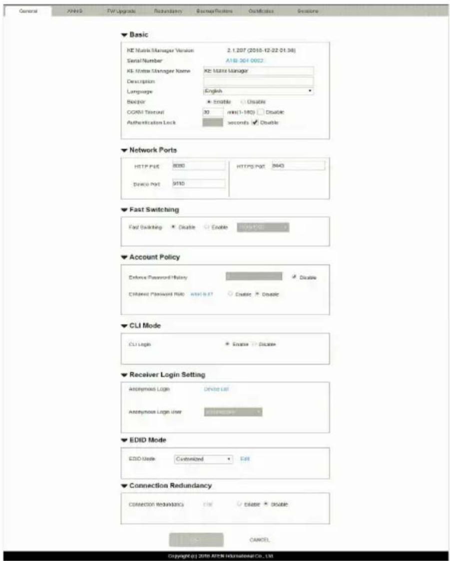
| Heading Item Description | ||
| Basic KE Manager Version This provides the version of the KE Manager software. | ||
| Serial Number This provides the serial number and a link to upgrade the software. | ||
| KE Manager Name Enter a name for the KE Manager. | ||
| Description Enter a description for the KE Manager. | ||
| Language Select the language for the KE Manager. Choices are: English, Chinese (Traditional), Simplified Chinese, Japanese, German, Korean, Russian, French, Spanish, and Portuguese. | ||
| Beeper Select Enable to sound a beep from the Transmitter/Receiver every time a configuration change is made. | ||
| CCKM Timeout If there is no user input for the amount of time entered in the box, a user logged into the CCKM is automatically logged out. Check Disable to turn this function off. | ||
| Authentication Lock This function is only supported by KE6910/KE6912. When accidental power cut happens, the function allows the user to retain his/her settings as was shown before the power cut. The user keeps the same authentication and display.◆ Uncheck Disable to turn this function on.◆ Specify a time (in seconds) you wish to keep the authentication and display for.When disabled or, if enabled, after the time specified above, the manager will prompt you to authenticate when you wish to access the KE Manager. | ||
| Network Ports | HTTP Port Sets the HTTP service port used to access the KE Manager. This is the port number to use for a browser login. The default is 8080. | |
| Device Port | Sets the Device service port used to access the KE Manager. Configure this port number on the Transmitter and Receiver to access to the KE Manager software (see Manager Address, page 142 and 134). The default is 9110. | |
| HTTPS Port | Sets the HTTPS service port used to access the KE Manager. This is the port number to use for a secure browser login. The default is 8443.Example: To access the KE Manager with an IP address of 192.168.0.100 using a secure browser login, enter: https://192.168.0.100:8443 | |
| Fast Switching Select the default resolution to use so that you can switch faster when changing Receiver to Transmitter connections. If the monitor you are using does not support fast switching the video may not display correctly when this setting is enabled.Note: Make sure to disable Boundless Switching when Fast Switching is enabled. | ||
| Account Policy | Enforce Password History | This setting determines the number of unique new passwords that must be used before an old password can be reused. Uncheck the box and enter a number to enforce the password history policy. |
| Enhance Password Rule | Select Enable to enforce rules for creating passwords, as follows:◆ The password length must be at least 8 characters.◆ The password must contain both upper and lowercase characters.◆ The password must contain a number (0 through 9).◆ If a user types in the wrong password 5 times consecutively, their account will be locked out for 10 minutes. | |
| CLI Mode CLI Mode Login Use the radio button to Enable or Disable command line interface logins to the KE Manager.Warning: If Disable CLI Mode Login is selected, anybody can login via Telnet with administrator privileges without needing to authenticate, allowing control of the entire installation. For installations requiring a high level of security, it's recommended that Enable CLI Mode Login be applied. | ||
| Receiver Login Settings | Anonymous Login Use | this to anonymously login a user at select Receivers. This option allows users to access the Receiver and connect to Transmitters without needing to login.Click Device List to display the list and check the box next to the Receiver(s) to enable the Anonymous Login feature. |
| Anonymous Login User | When Anonymous Login (above) is enabled for Receivers, select a user from the drop-down menu to use as the default account to anonymously login to the Receiver. | |
| EDID Mode | EDID Mode Use this drop-down menu to set the default EDID mode for all Transmitters. To set a different EDID mode for each Transmitter, use the drop-down menu to selectCustomizedand then clickEdit.A Transmitter list will appear with drop-down menus to configure each device's EDID mode. | |
| Connection Redundancy (KE6910 / 6912 only) | Use this drop-down menu to set connection redundancy function. You can setup priority connection with this function.Please refer to Connection Redundancy (KE6910 / 6912 only) on page 228. | |
| Save Click to save the changes. | ||
| Cancel Click to cancel the changes. | ||
Connection Redundancy (KE6910 / 6912 only)
You can setup priority connection for receivers. Where a transmitter fails, this function allows the receiver to connect to the transmitter of the highest priority that is available.
Follow the steps below to setup the priority list.
- Click Enable to enable this function.
- Click Edit. A window will pop-up to allow editing.
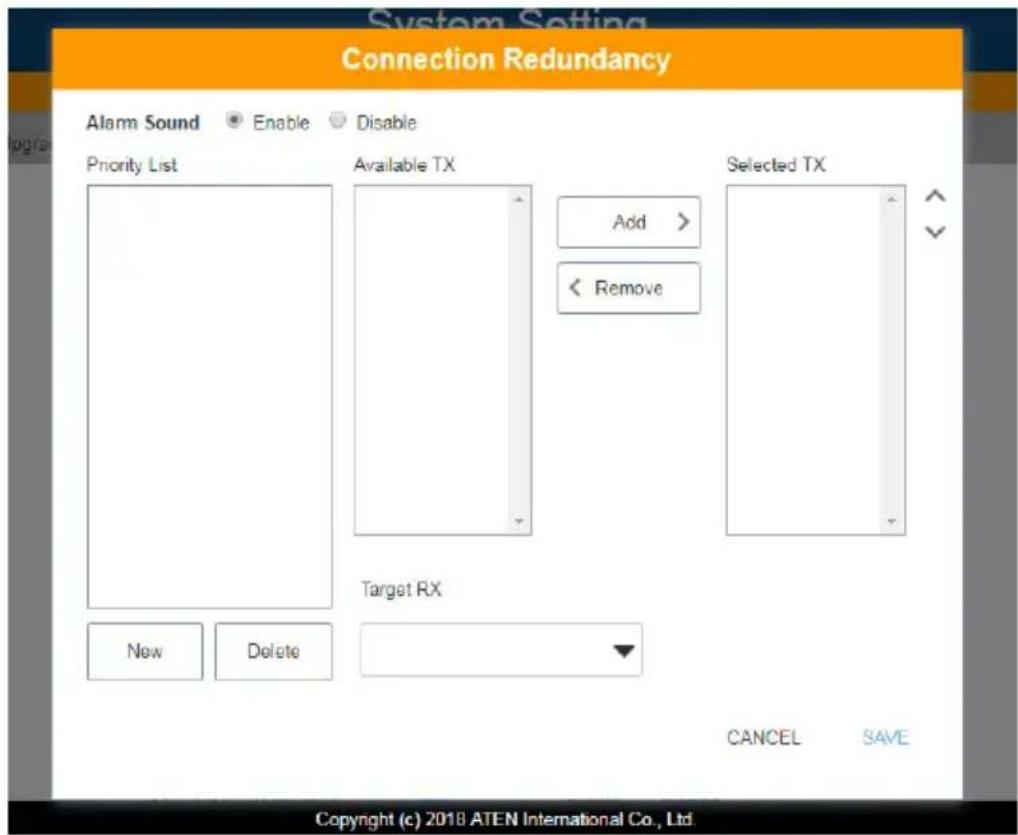
- For Alarm Sound, click Enable.

- To create a new list, click New. A Priority List 1 will be shown. (Click New again to create another list.)
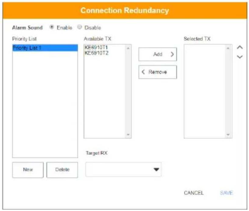
- Select the transmitters you wish to be in the list from the “Available TX” list and click Add. The added transmitter will be shifted to the “Selected TX” list.
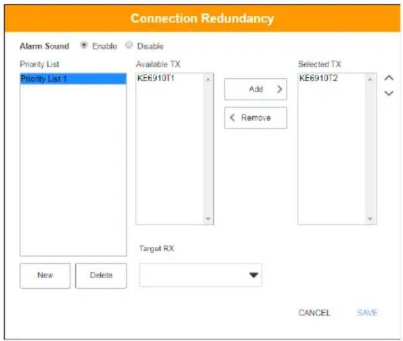
To deselect the transmitter, click to select the transmitter from the “Selected TX” list and click Remove. The transmitter will be shifted back to the “Available TX” list.
- Select a target receiver by first clicking the drop-down menu “Target RX”, and select a receiver.
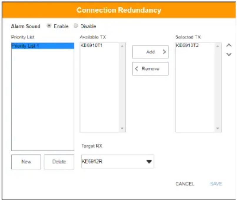
- Repeat steps 4-6 to add more priority lists.
- Click Save to save the settings.
ANMS
The ANMS (Advanced Network Management Settings) tab is used to set up login authentication and authorization management from external sources. It is organized with two pages – each with a series of related panels, as described below.
Event Destination
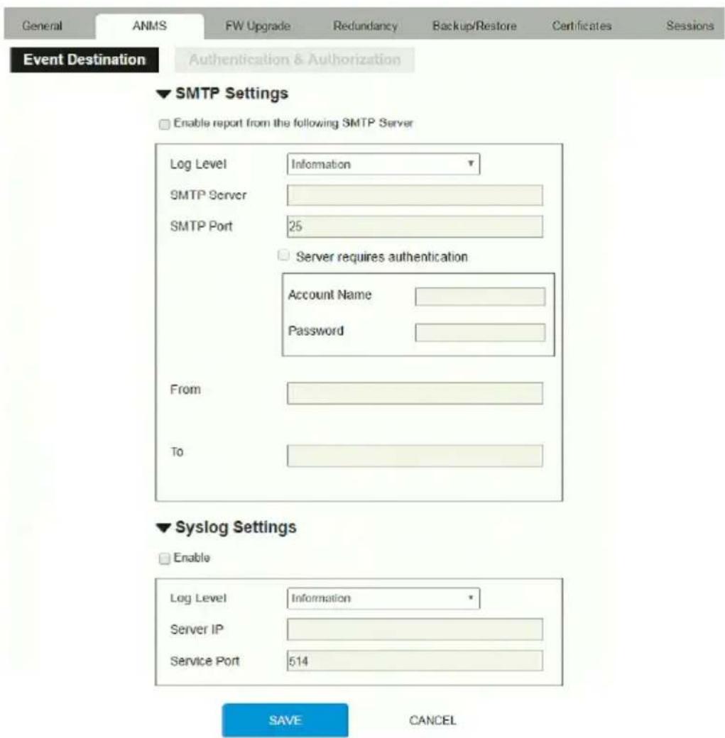
- SMTP Settings
To have the KE Manager email reports from the SMTP server to you, do the following:
-
Enable the Enable report from the following SMTP Server, select the Log Level (Information, Warning, or Error), and key in the SMTP Server IP address and SMTP Port.
-
If your server requires authentication, check the Server requires authentication checkbox, and key in the appropriate information for the Account Name and Password fields.
-
Key in the email address of where the report is being sent from in the From field.
Note: 1. Only one email address is allowed in the From field, and it cannot exceed 64 Bytes.
-
1 Byte = 1 English alphanumeric character.
-
Key in the email address (addresses) of where you want the SMTP reports sent to in the To field.
Note: If you are sending the report to more than one email address, separate the addresses with a semicolon. The total cannot exceed 256 Bytes.
- Click Save.
♦ Syslog Settings
To record all the events that take place on the KE Manager and write them to a Syslog server, do the following:
- Check Enable.
- Use the drop-down menu to select the Log Level (Information, Warning, or Error).
- Key in the Server IP address of the Syslog server.
- Key in the Service Port number. The valid port range is 1-65535.
- Click Save.
Authentication & Authorization
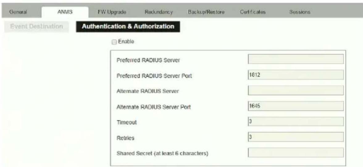
♦ RADIUS Settings
To allow authentication and authorization through a RADIUS server, do the following:
- Check Enable.
- Fill in the IP addresses and service port of the Preferred RADIUS Server and Alternate RADIUS Server.
- In the Timeout field, set the time in seconds that the KE Manager waits for a RADIUS server reply before it times out.
- In the Retries field, set the number of allowed retries.
-
In the Shared Secret field, key in the character string that you want to use for authentication between the KE Manager and the RADIUS Server. A minimum of 6 characters is required.
-
On the RADIUS server, Users can be authenticated with any of the following methods:
-
Use the same Username on both the RADIUS server and the KE Manager.
- Use the same Group name on both the RADIUS server and the KE Manager.
- Use the same Username/Group name on both the RADIUS server and the KE Manager.
In each case, the user's access rights are the ones assigned that were assigned when the User or Group was created on the KE Manager.
◆ LDAP / AD Settings:
▼ LDAP / AD Settings

Enable
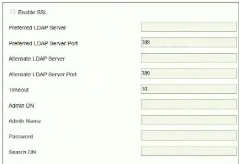
To allow authentication and authorization for the KE Manager via LDAP / AD, refer to the information in the table, below:
| Item Action | |
| Enable Put a check in the Enable checkbox to allow LDAP / AD authentication and authorization. | |
| Enable SSL Put a check in the Enable checkbox to allow SSL connections. | |
| LDAP Server IP and Port | Fill in the IP address and port number for the LDAP / AD server.♦ You can use the IPv4 address, the IPv6 address or the domain name in the LDAP Server field.♦ For LDAP, the default port number is 389. |
| Timeout Set the time | in seconds that the KE Manager waits for an LDAP / AD server reply before it times out. |
| Admin DN Consult the | the LDAP / AD administrator to ascertain the appropriate entry for this field. For example, the entry might look like this:ou=kn4132,dc=aten,dc=com |
| Admin Name Key in | the LDAP administrator's username. |
| Password Key in the | LDAP administrator's password. |
| Search DN Set the | distinguished name of the search base. This is the domain name where the search starts for user names. |
On the LDAP / AD server, Users can be authenticated with any of the following methods:
- With MS Active Directory schema.
Note: If this method is used, the LDAP schema for MS Active Directory must be extended. Without schema – Only the Usernames used on the KE Manager are matched to the names on the LDAP / AD server. User privileges are the same as the ones configured in the KE Manager.
- Without schema – Only the Usernames used on the KE Manager are matched to the names on the LDAP server. User privileges are the same as the ones configured in the KE Manager software.
- Without schema – Only Groups in AD are matched. User privileges are the ones configured for the groups he belongs to in the KE Manager.
- Without schema – Usernames and Groups in AD are matched. User privileges are the ones configured for the User and the Groups in the KE Manager.
♦ TACACS+ Settings:
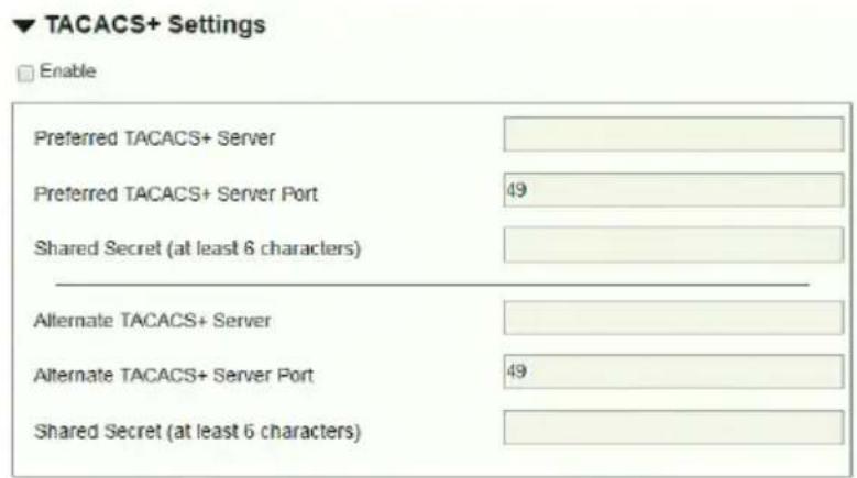
- Enable TACACS+ and enter the following information:
- Preferred TACACS+ Server
- Preferred TACACS+ Service Port
- Shared Secret 1
Alternate TACACS+ Server
Alternate TACACS+ Service Port - Shared Secret 2
FW Upgrade
In FW Upgrade all KE devices that are online are listed, allowing you to select which devices get upgraded. New firmware versions can be downloaded from our website as they become available. Check the website regularly to find the latest upgrade packages.
To upgrade the firmware do the following:
- Go to our website and download the firmware upgrade package appropriate to your KE device.
- Open your browser and log in to the KE Manager with an administrator's account.
- Click the Settings icon; select the FW Upgrade tab, the FW Upgrade page appears:
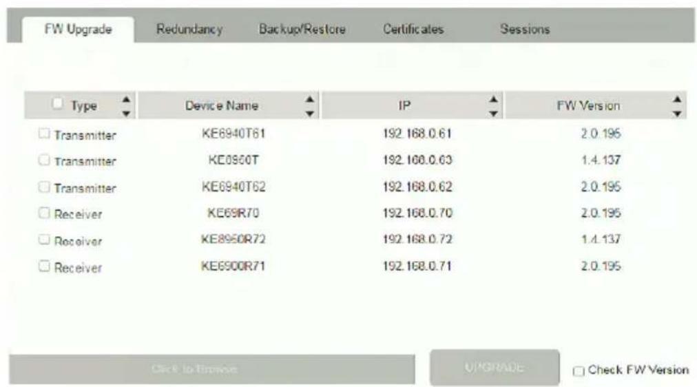
All the devices that are capable of being upgraded are listed.
Note: Only online devices show up in the list. Offline devices do not get upgraded.
- Check the checkbox in front of the devices you want to upgrade. Uncheck the devices that you do not want to upgrade.
- Click Browse. Navigate to the directory where the firmware upgrade file is located and select it.
- Enable or disable Check FW Version
- If you enabled Check FW Version the current firmware level is compared with that of the upgrade file. If the current version is equal to
or higher than the upgrade version, a popup message appears, to inform you of the situation and stops the upgrade procedure.
- If you didn't enable Check FW Version, the upgrade file is installed without checking what its level is.
-
If you cancel the firmware upgrade, you have to wait 12 seconds before you can disable Check FW Version and restart the firmware upgrade.
-
Click Upgrade to start the upgrade procedure. As the upgrade proceeds, progress information is shown on the screen. Once the upgrade completes successfully, the devices will reset.
- Log in to each device and check the firmware version to be sure it is the new one.
Firmware Upgrade Recovery
If the Upgrade Succeeded screen doesn't appear or the upgrade procedure is abnormally halted (due to computer crash, power failure, etc.), the device may become inoperable. If you find that the device does not work following a failed or interrupted upgrade, do the following
- Power off the KE device.
- Press the Reset button, then power on the KE device while holding Reset.
- Hold Reset for 7 seconds after the device is powered on.
- The device will revert to a previous firmware version and recover from the failure.
- Upgrade the firmware to the most current version available.
Redundancy
The Redundancy tab allows you to set up a backup computer in case the computer hosting the KE Manager goes offline. If the KE Manager goes offline, the secondary computer will automatically take over operations, allowing all connections to continue without disruption – with only a brief period of 30 seconds when new connections can't be started. When the primary computer comes back online it retrieves the updated database from the secondary computer and re-takes all KE Manager operations.
To set up Redundancy, do the following:
- Install KE Manager on a secondary computer with a USB license key. For detailed instructions, see page 161.
Note: A second USB license key is required if you have more than 8 KE Series devices in your setup.
- On the secondary computer, log in to the KE Manager, click and go to the Redundancy tab.
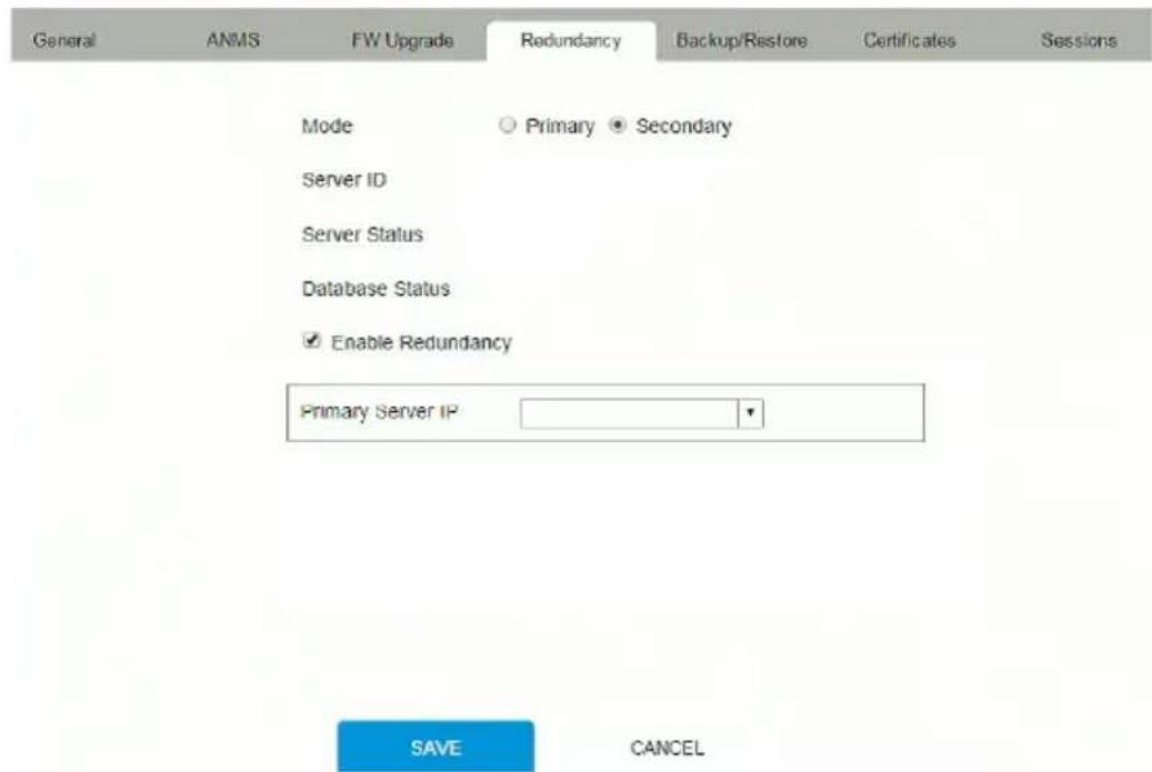
-
Check Enable Redundancy and select the Secondary radio button.
-
Use the Primary Server IP drop-down menu to select the primary IP address.
-
Click Save.
-
Redundancy is now running on the secondary computer.
-
On the primary computer, log in to the KE Manager, click 📄 and go to the Redundancy tab.
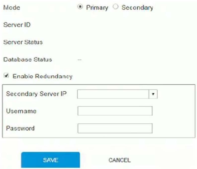
- Check Enable Redundancy and select the Primary radio button.
- Use the Secondary Server IP drop-down menu to select the secondary IP address.
- Enter the Username and Password of the secondary computer's local administrator account.
- Click Save.
- Information about the Redundancy status can be found in the event log (see Log, page 224 for details).
Backup / Restore
The Backup/Restore tab is divided into three panels: Backup, Restore, and Export Device List:
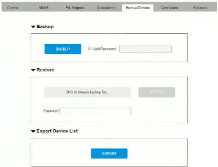
The operations to perform backup/restore procedures are described in the table below and in the section that follows:
| Procedure Operation | |
| Backup Backs up | theKE Manager configuration – including Receiver,Transmitter, Profile and Schedule configurations; user and group accounts, user profiles, logs, and system settings. |
| Restore | Deletes the current Receiver, Transmitter, Profile and Schedule configurations; user and group accounts, user profiles, logs, and system settings.; then restores those settings to the values that exist in the previously saved backup file. |
| Export Device List | Clicking Export allows you to save a file with a complete list of the devices added to the KE Manager. The file contains the ID, Name, Description and IP Address of each Transmitter and Receiver. An Existing column also lists if the device is available: Yes, it exists and is available, or No, it is offline or has been removed. |
Backup
To back up system configuration settings, do the following:
- (Optional) In the Backup panel, check Add Password, and provide a password for the backup file.
Note: Providing a password is a security feature – if you provide a password, you will need to give the same password in order to restore the configuration settings from this file.
- Click Backup.
- In the dialog box that comes up, Click Save to save the configuration file (System.conf) to a location on your hard disk.
- Navigate to the directory where you want to save the file and click Save.
Restore
To restore system configuration settings, do the following:
- In the Restore panel, click Browse.
- Navigate to the directory where the backup file is located and select it.
- When you return to the Backup/Restore page enter the password you set when the backup file was created.
Note: If you did not set a password for the file, leave the field blank.
- Click Restore.
- Click OK to confirm that you want to restore the configuration data. When the Restore procedure is in process, a message stating that the KE Manager will restart will appear. After a short while the KE Manager closes and refreshes at the log in screen. When it comes back up the configuration settings that were restored from the backup file are in effect.
Certificates
This tab provides information about Private Certificates:

Private Certificate
When logging in over a secure (SSL) connection, a signed certificate is used to verify that the user is logging in to the intended site. For enhanced security, the Private Certificate section allows you to use your own private encryption key and signed certificate, rather than the default ATEN certificate.
There are two methods for establishing your private certificate: generating a self-signed certificate; and importing a third-party certificate authority (CA) signed certificate.
- Generating a Self-Signed Certificate
If you wish to create your own self-signed certificate, a free utility – openssl.exe – is available for download over the web. See Self-Signed Private Certificates, page 328 for details about using OpenSSL to generate your own private key and SSL certificate.
- Obtaining a CA Signed SSL Server Certificate
For the greatest security, we recommend using a third party certificate authority (CA) signed certificate. To obtain a third party signed certificate,
go to a CA (Certificate Authority) website to apply for an SSL certificate. After the CA sends you the certificate and private encryption key, save them to a convenient location on your computer.
- Importing the Private Certificate
To import the private certificate, do the following:
- Click Import from the bottom of the Private Certificate page, shown here:

- Click Browse to the right of Certificate Filename; and browse to where your certificate file is located; and select it.
- Click Import to complete the procedure.
Note: Clicking Restore Defaults returns the device to using the default ATEN certificate.
Certificate Signing Request
The Certificate Signing Request (CSR) section provides an automated way of obtaining and installing a CA signed SSL server certificate.
To perform this operation do the following:
- Click New. The following dialog box appears:

- Fill in the form – with entries that are valid for your site – according to the example information in the following table:
| Information Example |
| Country (2 letter code) TW |
| Information Example | |
| State or Province Taiwan | |
| Locality Taipei | |
| Organization Your Company. | Ltd. |
| Organization Unit Tech Department | |
| Common Name mycompany.com | Note: This must be the exact domain name of the site that you want the certificate to be valid for. If the site's domain name is www.mycompany.com, and you only specify mycompany.com, the certificate will not be valid. |
| Email Address administrator@yourcompany.com | |
- After filling in the form (all fields are required), click Create.
A self-signed certificate based on the information you just provided is now stored on the KE Manager software.
- Click Get CSR, and save the certificate file (csr.cer) to a convenient location on your computer.
This is the file that you give to the third party CA to apply for their signed SSL certificate.
- After the CA sends you the certificate, save it to a convenient location on your computer. Click Import to locate the file; then click Import to store it on the KE Manager.
Note: When you upload the file, the KE Manager checks the file to make sure the specified information still matches. If it does, the file is accepted; if not, it is rejected.
If you want to remove the certificate (to replace it with a new one because of a domain name change, for example), simply click Restore Defaults.
Sessions
The Sessions tab shows all of the users that are logged into KE Manager and OSD sessions and provides information concerning the “who, where and when” of each session. This page also gives the administrator the option of forcing a user logout by selecting the user and clicking Kill Session next to each user.
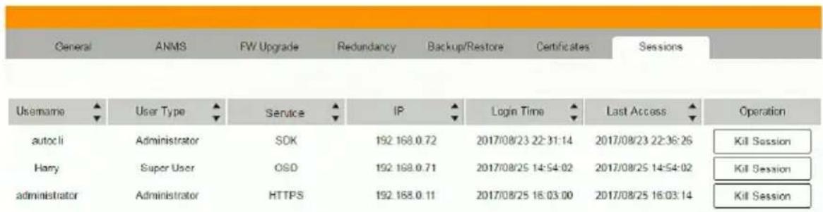
◆ Username refers to the user that logged in to establish a session.
◆ User Type refers to the account type of the user.
- Service refers to how the user logged into their session – via KE Manager, Command Line, or OSD.
◆ IP refers to the IP address from which the user has logged in.
- Login Time refers to the date/time that the user logged into the session.
- Last Access refers to the last time the user session was active.
◆ Operation provides the Kill Session button to force a user logout.
This Page Intentionally Left Blank
Chapter 8
Connections
Overview
The Connections panel is found on the KE Matrix Manager Main Page, just below System Status. Connections provides a diagram of current Transmitter to Receiver connections. Before connections are established the panel appears blank, as shown below. To connect Receivers to Transmitters, use the Instant Link panel (page 176), or create a connection Profile (page 219).
When connections are made, clicking a device in the left column provides a way to view the connection, hovering the mouse cursor over the connection diagram in the right column allows you to disconnect the device, as explained in the sections that follows.
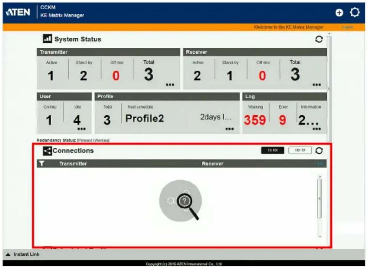
Connections
When Receivers connect to Transmitters, they appears in the Connections panel. There are two columns – each lists either Transmitters or Receivers. The columns can be swapped by click the TX-RX or RX-TX button. Devices in the left column can be clicked to display their connection to devices, shown in the right column. Connections, shown in the right column, can be disconnected by clicking the X over the connection diagram.
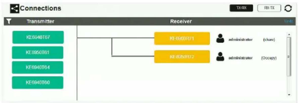
flowchart
graph TD
    A["Transmitter KE6040T67"] --> B["Receiver KE-6900R71"]
    C["Transmitter KE8950T61"] --> B
    D["Transmitter KE6940T64"] --> B
    E["Transmitter KE6940T60"] --> B
    B --> F["Administrator (share)"]
    B --> G["Administrator (Occupy)"]
| Item Description | |
 | On the heading bar under Connections, click this icon to change the sort order of the Transmitters or Receivers listed in the left column. |
| Left Column Click a device in | the left column to view its connection in the right column. A diagram to its connected device(s) appears in the right column. |
| Right Column The right column | displays a connection diagram when a device in the left column is selected. Move the mouse cursor over the diagram and click X to disconnect the devices. This column also shows the user and access type (Exclusive, Occupy, Share, View Only) used to establish the connection. |
| Transmitter Lists Transmitters | that are online and connected to Receivers. |
| Receiver Lists Receivers that | are online and connected to Transmitters. |
 | Click to view Transmitter to Receiver connections. This will list Transmitters in the left column so that they can be selected to view their connection diagram, shown in the right column. |
 | Click to view Receiver to Transmitter connections. This will list Receivers in the left column so that they can be selected to view their connection diagram, shown in the right column. |
| Click this icon to Refresh the Transmitters and Receivers list in Connections panel. | |
| Undo Click this icon to undo | the most recent disconnection. |
This Page Intentionally Left Blank
Overview
The Scheduled Profile panel is found on the KE Matrix Manager Main Page, just below Connections. Scheduled Profiles displays connection profiles that have been scheduled. Click Go to Schedule to edit and create profile schedules (page 223). To create Profiles, see page 219.
![CCKM KE Matrix Manager Welcome to the KE Matrix Manager 1 4 3 Profile2 2days I... 359 9 2... Redundancy Status: [Primary] [Working] Connections TX-AX RX-TX Receiver Transmitter Scheduled Profile Go to Schedule Profile Description Start End Status Profile2 2017-09-01 01:00 2017-09-01 04:00 2days later Profile1 2017-10-18 05:10 2017-10-13 06:45 4days later Instant Link Copyright (c) 2016.ATEN International Co., Ltd.](/content/2026/05/1059622/images/efbb3d503d930a80825ed026c3b09d98e9b48ce403469f4fb33ea22f439502b0.jpg)
| Item Description | |
| Headings | The headings provide the schedules: Name, Description, Start, End, and Status. Start and End show the time/date the profile is scheduled to begin and end. Status displays the number of days until to the next scheduled run. |
| Go to Schedule | Clicking Go to Schedule opens the Profile settings page which allows you to create and edit connection profiles. See Profile, page 219 for details. |
| Click this icon to Refresh the connections list in the right column. | |
| Undo Click this icon to undo | the most recent disconnection. |
This Page Intentionally Left Blank
Chapter 10 Sessions
Overview
The Sessions panel is found at the bottom of the KE Matrix Manager Main Page, just below Scheduled Profile. Sessions displays information about users logged into devices and the KE Matrix Manager web GUI. Click Go to Sessions to view the settings page (see page 245).
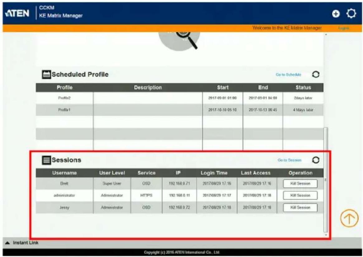
| Item Description | |
| Headings The headings provide information about each user session:Username,User Level,Service,IP,Login Time, andLast Access. For more details about each heading, see Sessions, page 245. | |
| Go to Sessions | Clicking Go to Sessions opens the Sessions settings page which provides a page displaying the same information found in this panel. |
| Click this icon to Refresh the Sessions list. | |
This Page Intentionally Left Blank
Chapter 11
Firmware Upgrade Utility
The Windows-based Firmware Upgrade Utility (FWUpgrade.exe) provides a smooth, automated process for upgrading the firmware. The Utility comes as part of a Firmware Upgrade Package that is specific for each device. New firmware upgrade packages are posted on our web site as new firmware revisions become available. Check the web site regularly to find the latest packages and information relating to them:
http://www.aten.com
For browser based firmware upgrade, please refer to FW Upgrade on page 236.
Preparation
- From a computer that is not part of your installation go to our Internet support site and choose the model name that relates to your KE device to get a list of available Firmware Upgrade Packages.
- Choose the Firmware Upgrade Package you want to install (usually the most recent), and download it to your computer.
- Be sure that the computer is connected to the same LAN segment as the KE devices.
Starting the Upgrade
To upgrade your firmware:
- Run the downloaded Firmware Upgrade Package file - either by double clicking the file icon, or by opening a command line and entering the full path to it. The Firmware Upgrade Utility Welcome screen appears:
![Firmware Upgrade Utility Welcome to the Firmware Upgrade Utility. Put your device into Firmware Upgrade Mode. Use the Firmware Upgrade Cable to connect its Firmware Upgrade Port in your computer (or connect via Ethernet). Agree to the License Agreement; Then Click Next. LICENSE AGREEMENT LICENSE GRANT A IEN International Co., Ltd. ("Licensor") wants to you a non-exclusive, non-transferable license to access and use FIRMWARE UPGRADE UTILITY (the "Product") during the "Term" set forth below. You may install the Product on a hard disk or other storage device; install and use the Product on a file server for use on a network for the purpose of (i) permanent installation onto hard disks or other storage devices or (ii) use of the Product over such network; and make backup copies of the Product. RESTRICTIONS You agree not to modify, adapt, translate, reverse engineer, recompile, discernible or otherwise attempt to discover the source code of the Product, or create derivative works based on the Product, or remove any proprietary notices or labels on the Product, including copyright, trademark or patent pending notices. You may not sublicense the Product or otherwise allow others to use the Product licensed to you. • ] Agree ○ [ Don't Agree Help About < Back Next > Cancel](/content/2026/05/1059622/images/5f195720c3ce25c41fb8cbb41d3577e379f057d6dacc9cafe6154feb4ecde9c0.jpg)
Note: The screens shown in this section are for reference only.
- Read the License Agreement (enable the I Agree radio button).
- Click Next. The Firmware Upgrade Utility main screen appears:
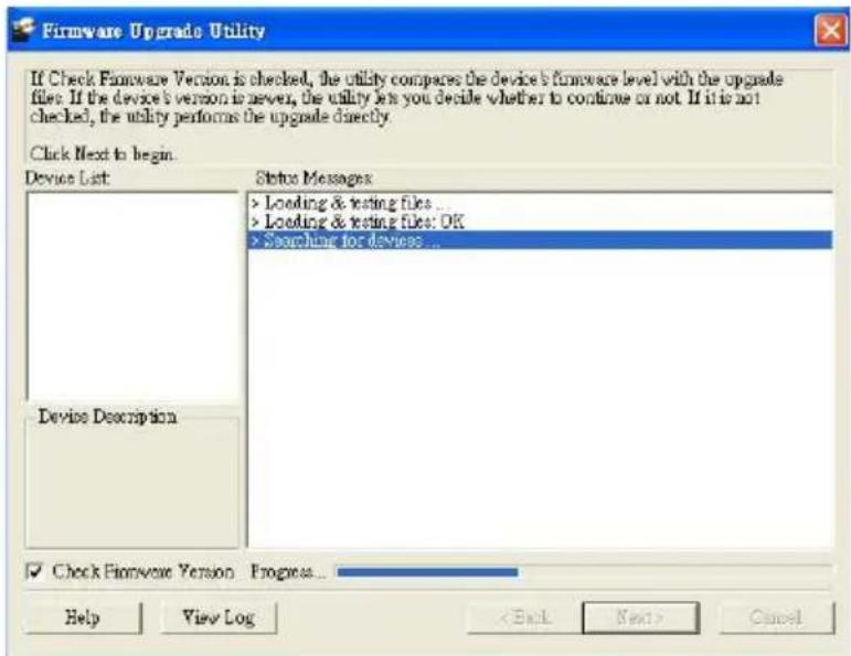
- The Utility inspects your installation. All the devices capable of being upgraded by the package are listed in the Select Master Device list.
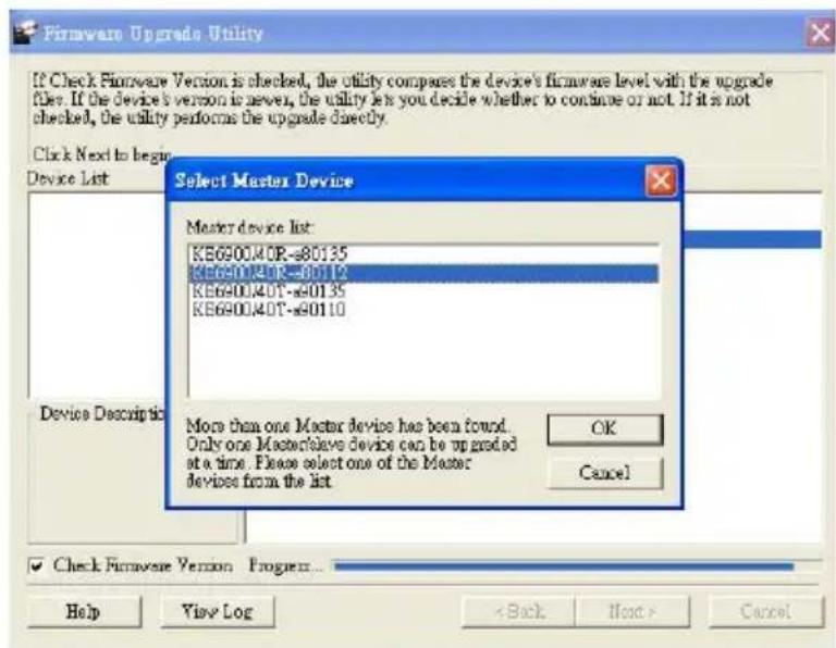
- After you have made your device selection, Click OK and then Next to begin the upgrade.
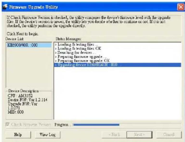
If you enabled Check Firmware Version, the Utility compares the device's firmware level with that of the upgrade files. If it finds that the device's version is higher than the upgrade version, it brings up a dialog box informing you of the situation and gives you the option to Continue or Cancel.
If you didn't enable Check Firmware Version, the Utility installs the upgrade files without checking whether they are a higher level, or not.
As the Upgrade proceeds status messages appear in the Status Messages panel, and the progress toward completion is shown on the Progress bar.
Upgrade Succeeded
After the upgrade has completed, a screen appears to inform you that the procedure was successful:
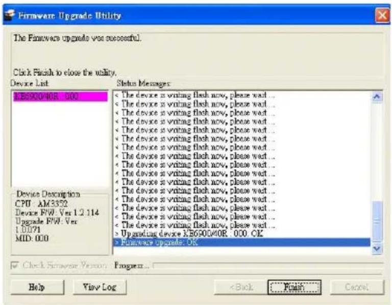
Device/Profile Commands
When typing a device or profile into a command string, you can enter the name by: IP address (device only), ID or @ with the List number for the device/profile in the command line interface. Note: To find out about the List number for a device/profile, execute a List command (page 278).Telnet
The KE Series can be operated and configured via a remote terminal session using Telnet. This is a useful means for configuring devices when they are first setup and connected to the network. To log into the KE Series device by means of a Telnet session, do the following: 1. On your computer, open a terminal (command line) session. 2. At the prompt, key in the KE device's IP address with port 9130 in the following way: telnet [IP address] [port] 3. Press Enter. The login screen appears. At the login prompt, provide the Password. Verification
After sending a command, a verification message appears at the end of the command line. Use the echo command to identify a command by number: - Command OK - the command is correct and performed successfully - Command incorrect - the command has the wrong format and/or values. - Echo Command - at the end of a command string, type: e1234 – where 1234 can be any number. The verification message returns with the echo number.Switch Port Command
The formula for Switch Port commands is as follows: $$ \begin{array}{l} \text {Command + Output + Num1 + Input + Num2 + Mode + Stream +} \\ \text {Connect + [Enter]} \end{array} $$ 1. For example, if you want to switch the Receiver's connection to Transmitter (192.168.0.20), type the following: $$ \text { sw i192.168.0.20 [Enter] } $$ 2. For example, if you want to disconnect the Receiver from its Transmitter connections, type the following: $$ \text { sw off } [ \text { Enter } ] $$ 3. For example, if you want to connect Receiver (192.168.0.99) to Transmitter (192.168.0.79) with exclusive access to stream video and audio, type the following: $$ \text { sw o192.168.0.99 i192.168.0.79 exclusive video audio on [Enter] } $$ 4. For example, to disconnect Receiver (192.168.0.11) from the video stream and return it to the OSD menu, type the following: $$ \text { sw o192.168.0.11 off [Enter] } $$ 5. For example, to disconnect Receiver (192.168.0.09) from the video stream and logout the OSD, type the following: $$ \text { sw o192.168.0.09 logout [Enter] } $$ 6. For example, to disconnect the Receiver's USB stream, type the following: $$ \text { sw usb off } [ \text { Enter } ] $$ 7. For example, to switch the Receiver to the 5th Transmitter listed in the command line interface, type the following: $$ \text { sw i@5 exclusive all on [Enter] } $$ 8. For example, to switch the Receiver to the 7th Transmitter listed in the command line interface with echo command 4312, type the following: $$ \text { sw i@7 exclusive all on e4312 } $$ 9. For example, to switch Receiver (192.168.0.12) to the 14th Transmitter listed in the command line interface with occupy access to stream video audio and USB, type the following: $$ \text { sw o192.168.0.12 i@14 occupy video audio usb on [Enter] } $$ The following tables show the possible values for the Switch Port commands:| Command Description | |
| sw Switch port command | |
| Output Description | |
| o Output port command (RX) | |
| Num1 Description | |
| xx Output port | xx: Receiver ID or IP address |
| @zz List # | zz: 1~99To use the 4th Receiver listed in the command line interface,type: o@4 |
| Input Description | |
| i Input command (TX) | |
| Num2 Description | |
| yy Input port | yy: Transmitter ID or IP address |
| @zz List # | zz: 1~99To use the 8th Transmitter listed in the command line interface,type: i@8 |
| Mode Description | |
| exclusive Sets | the Access Mode to exclusive. |
| share Sets | the Access Mode to share. |
| occupy Sets | the Access Mode to occupy. |
| viewonly | Sets the Access Mode to view only. If the mode is omitted, view only is used by default. |
| Stream | Description |
| video | Sets the video source stream |
| audio | Sets the audio source stream |
| serial | Sets the serial source stream |
| Stream | Description |
| usb Sets the USB source stream | |
| all Sets all source streams | |
| Connect Description | |
| on Connect | |
| off Disconnect | |
| logout Logout OSD | |
| Command | Output | Num1 | Input | Num2 | Mode | Stream | Connect | Description | |
| sw o xx | i yy | exclusive | video | audio serial usb all | on | Switch output xx to input yy with exclusive access to source(s).xx: Receiver IDyy: Transmitter ID | |||
| sw o xx | i yy share | video | audio serial usb all | on | Switch output xx to input yy with share access to stream source(s).xx: Receiver IDyy: Transmitter ID | ||||
| sw o xx | i yy | occupy | video | audio serial usb all | on | Switch output xx to input yy with occupy access to stream source(s).xx: Receiver IDyy: Transmitter ID | |||
| sw o xx | i yy | viewonly | video | audio serial usb all | on | Switch output xx to input yy with viewonly access to stream source(s).xx: Receiver IDyy: Transmitter ID | |||
| sw o xx | off Switch output xx, disconnect streams, return to OSD menu.xx: Receiver ID | ||||||||
| sw o xx | logout Switch output xx, disconnect streams and logout from OSD menu.xx: Receiver ID | ||||||||
| sw | video audio serial usb all | off | Switch Receiver stream(s) to disconnect. | ||||||
| Command | Output | Num1 | Input | Num2 | Mode | Stream | Connect | Description | |
| sw off Switch Receiver | disconnect streams, return to OSD menu. | ||||||||
| sw i @zz exclusive | share occupy viewonly | video audio serial usb all | on Switch | Switch Receiver to input @zz with [mode] access to stream source(s). zz: Transmitter # by order listed in the command line interface. | |||||
| sw o xx i @zz exclusive | video | audio serial usb all | on Switch | Switch output xx to input @zz with [mode] access to stream source(s). xx: Receiver ID zz: Transmitter # by order listed in command line interface. | |||||
Mute Command
The Mute command allows you to enable or disable the audio. The formula for the Mute command is as follows: $$ \text { Command } + \text { Output } + \text { Num1 } + \text { Control } + [ \text { Enter } ] $$ 1. For example, to turn mute off (audio on) for the Receiver, type the following: $$ \text { mute off } [ \text { Enter } ] $$ 2. For example, to turn mute on for Receiver (192.168.0.11), type the following: $$ \text { mute o192.168.0.11 on [Enter] } $$ 3. For example, to turn mute off for Receiver (192.168.0.18), type the following: $$ \text { mute o192.168.0.18 off [Enter] } $$ The following tables show the possible values for the Mute commands:| Command Description | |
| mute Mute command | |
| Output Description | |
| o Output port command | |
| Num1 Description | |
| xx Output number | |
| Control Description | |
| on Mute on; audio disabled | |
| off Mute off; audio enabled (default) |
| Command Output Num1 Control Description | ||||
| mute | o | xx | on | Turn mute on for output xx xx: Receiver ID |
| mute | o | xx | off | Turn mute off for output xx xx: Receiver ID |
| Command Output Num1 | Control Description | |
| mute on Turn mute on for | Receiver | |
| mute off Turn mute off for | Receiver |
Profile Command
The Profile command allows you to connect profiles and video walls. The formula for Profile commands is as follows: $$ \text { Command } + \text { Profile } + \text { Num1 } + \text { Control } + [ \text { Enter } ] $$ 1. For example, to connect profile 8 and lock the OSD menu, type the following: $$ \text { profile f8 } [ \text { Enter } ] $$ 2. For example, to connect profile 4 with access to the OSD menu, type the following: $$ \text { profile f4 release [Enter] } $$ 3. For example, to disconnect profile 12 and return to the Receiver to the OSD menu, type the following: $$ \text { profile f12 back [Enter] } $$ The following tables show the possible values for the Profile commands:| Command Description | |
| profile Profile command | |
| Profile Description | |
| f Profile ID | |
| Num1 Description | |
| xx Profile | or Video Wall ID |
| xx: 1-99 | |
| Control Description | |
| lock Connect profile, lock access to OSD menu (default) | |
| release Connect profile, allow access to OSD menu | |
| back Disconnect profile, return Receiver to OSD menu | |
| Command | Profile | Num1 | Control | Description |
| profile f xx lock Connect profile xx, lock | OSD accessxx:1~99 | |||
| profile f xx release Connect profile xx, allow | OSD accessxx:1~99 | |||
| profile f xx | back | Disconnect profile xx | and return Receiver to OSD menuxx: 1~99 | |
EDID Command
Extended Display Identification Data (EDID) is a data that contains a display's basic information and is used to communicate with the video source. The EDID commands allow you to change the EDID setting of a Transmitter. For more information on configuring EDID settings, see Properties, page 141. The formula for the EDID command is as follows: $$ \text { Command } + \text { Address } + \text { Number } + \text { Control } + [ \text { Enter } ] $$ 1. For example, if you want to configure device (192.168.0.3) to use the remix EDID mode, type the following: edid a192.168.0.3 remix [Enter] The following tables show the possible values for the EDID commands:| Command Description | |
| edid EDID command | |
| Address Description | |
| a Address command | |
| Number Description | |
| xx Address | numberxx: Receiver ID or IP address |
| Control Description | |
| auto Checks | the EDID of all connected displays and the ATEN default EDID to use the best common resolution for all displays. |
| remix Manually | checks the EDID of all connected displays and the ATEN default EDID to use the best common resolution for all displays (see EDID Mode, page 150). |
| default Implements | ATEN's default EDID.(default) |
| manual Manually | set the EDID configuration from the Receiver's OSD (see EDID Mode, page 150). |
| Command | Address | Number | Control | Enter | Description |
| edid a xx | auto [Enter] | Set EDID | of address | xx to auto. | xx: Device ID or IP Address |
| edid a xx | remix [Enter] | Set EDID | of address | xx to remix. | xx: Device ID or IP Address |
| edid a xx | default [Enter] | Set EDID | of address | xx to default. | xx: Device ID or IP Address |
| edid a xx | manual | [Enter] | Set EDID | of address | xx to manual.xx: Device ID or IP Address |
Reset Command
The Reset command allows you to reset a device back to the default factory settings. Reset includes resetting the devices IP address. Note: The Reset command resets everything but the login information to the factory default settings. To reset the login information, refer to Reset All Information on page 329. The formula for the Reset command is as follows: $$ \text { Command } + \text { Address } + \text { Number } + [ \text { Enter } ] $$ 1. For example, to reset device (192.168.0.95), type the following: reset a192.168.0.95 [Enter] 2. For example, to reset the Receiver, type the following: reset [Enter] The following tables show the possible values for the Reset command:| Command Description | |
| reset Reset command | |
| Address Description | |
| a Address command | |
| Number Description | |
| xx Address number | |
| Command | Address | Num | Enter | Description |
| reset | a | xx | [Enter] | Reset address xx back to the factory default settingsxx: Device ID or IP Address |
| reset | [Enter] | Resets the Receiver settings |
RS-232 Command
The RS-232 command allows you to set the RS-232 settings for a device. The formula for the RS-232 command is as follows: $$ \begin{array}{l} \text {Command + Address + Number + Baud Rate + Parity + Data Bit +} \\ \text {Stop Bit + Flow Control [ Enter]} \end{array} $$ 1. For example, to set device (192.168.0.33) with a baud rate of 38400, parity of none, data bit of 8, and stop bit of 1, type the following: $$ \text { baud a192.168.0.33 38400 none 8 1 [Enter] } $$ 2. For example, to set the local device with a baud rate of 19200, type the following: $$ \text { baud 19200[Enter] } $$ The following tables show the possible values for the RS-232 command:| Command Description | |
| baud RS-232 command | |
| Address Description | |
| a Address command | |
| Num1 Description | |
| xx Address number | |
| Baud Rate Description | |
| 9600 Use 9600 baud rate | |
| 19200 Use 19200 baud rate | |
| 38400 Use 38400 baud rate | |
| 115200 Use 115200 baud rate | |
| Parity Description | |
| None Sets the parity to none | |
| Even Sets the parity to even | |
| Odd Sets the parity to odd | |
| Data Bit | Description |
| 5 Sets the data bit to 5 | |
| 6 Sets the data bit to 6 | |
| Data Bit Description | |
| 7 Sets the data bit to 7 | |
| 8 Sets the data bit to 8 | |
| Stop Bit Description | |
| 1 Sets the stop bit to 1 | |
| 2 Sets the stop bit to 2 | |
| Flow Control Description | |
| None Sets flow control to none | |
| Hardware Sets flow control to hardware | |
| Xon Sets flow control to Xon | |
| Xoff Sets flow control to Xoff | |
| Command | Address | Num 1 | Baud Rate | Parity | Data Bit | Stop Bit | Flow Control | Description |
| baud a | xx 9600 | None | Even Odd | 5678 | 12 | None Hardware Xon/Xoff | Set address xx baud rate to 9600, with parity/ data bit/ stop bit / flow control setting | |
| baud a | xx 19200 | None | Even Odd | 5678 | 12 | None Hardware Xon/Xoff | Set address xx baud rate to 19200, with parity/ data bit/ stop bit / flow control setting | |
| baud a | xx 38400 | None | Even Odd | 5678 | 12 | None Hardware Xon/Xoff | Set address xx baud rate to 38400, with parity/ data bit/ stop bit / flow control setting | |
| baud a | xx 115200 | None | Even Odd | 5678 | 12 | None Hardware Xon/Xoff | Set address xx baud rate to 115200, with parity/ data bit/ stop bit / flow control setting | |
| baud 9 | 600 Set local device | baud rate to 9600 | ||||||
| baud 1 | 9200 Set local device | baud rate to 19200 | ||||||
| baud 3 | 8400 Set local device | baud rate to 38400 | ||||||
| baud 1 | 15200 Set local device | baud rate to 115200 |
OSD Command
To enable or disable the On-Screen Display (OSD) menu for a Receiver, use the following command: $$ \text { Command } + \text { Output } + \text { Number } + \text { Control } + [ \text { Enter } ] $$ 1. For example, to enable the OSD for Receiver 192.168.0.51, type: osd o192.168.0.51 on [Enter] 2. For example, to disable the OSD for the local Receiver, type: osd off [Enter] The following tables show the possible values for the OSD command:| Command Description | |
| osd OSD command | |
| Output Description | |
| o Output command | |
| Number Description | |
| xx Output number | xx: Receiver ID or IP address |
| Control Description | |
| on Enable OSD functions | |
| off Disable OSD functions (default) | |
| Command | Output | Number | Control | Enter | Description |
| osd | o | xx | on | [Enter] | Enable OSD functions for output xxx: Receiver ID or IP address |
| osd | o | xx | off | [Enter] | Disable OSD functions for output xx off (default)xx: Receiver ID or IP address |
List Command
The List command allows you to retrieve information about users, settings and connections. The formula for the List command is as follows: $$ \text { Command } + \text { Output } + \text { Input } + \text { Number } + \text { Control [Enter] } $$ 1. For example, for a complete list of available channels, type the following: list channel [Enter] 2. For example, for a complete list of available profiles, type the following: list profile [Enter] 3. For example, to list all users logged into all OSD menus, type the following: 4. list login [Enter] 5. For example, to list the user logged into the OSD on Receiver (192.168.0.44), type the following: list o192.168.0.44 login [Enter] 6. For example, for a complete list of available connections, type the following: list connection [Enter] 7. For example, to list the current connections on Transmitter (192.168.0.88), type the following: list i192.168.0.88 connection [Enter] The following tables show the possible values for the List command:| Command Description | |
| list List command | |
| Output Description | |
| o Output command | |
| Input Description | |
| i Input command | |
| Number Description | |
| xx Output or | Input numberxx: Device ID or IP address |
| Control Description | |
| channel Lists information about the available channel(s) | |
| profile Lists information about the available profile and TV wall connections | |
| rx Lists information about the Receiver | |
| login Lists information about users logged into to the OSD menu | |
| connection Lists information about a Transmitters current connections | |
| Command | Output | Input | Number | Control | Description | |
| list o xx | login | List output xx user | logged into OSD. | |||
| list o xx | rx | List output xx Receiver | information | |||
| list | i | xx | connection | List input xxTransmitter information | ||
| list | channel | List all available channel information | ||||
| list | profile | List all available profile information | ||||
| list | rx | List information about all Receivers | ||||
| list | login | List information about all OSD logins | ||||
| list | connection | List information about all connections | ||||
Read Command
The Read command allows you to retrieve the properties of a device. The formula for the Read command is as follows: $$ \text { Command } + \text { Output } + \text { Input } + \text { Number } + \text { Control [Enter] } $$ 1. For example, to read all of the local Receiver's properties, type the following: $$ \text { read all } [ \text { Enter } ] $$ 2. For example, to read all of Receiver (192.168.0.19) device properties, type the following: $$ \text { read o192.168.0.19 all [Enter] } $$ 3. For example, to read all of Transmitter (192.168.0.28) device properties, type the following: $$ \text { read i192.168.0.28 all [Enter] } $$ 4. For example, to read the basic properties of Receiver (192.168.0.61), type the following: $$ \text { read o192.168.0.61 basic [Enter] } $$ 5. For example, to read the network properties of Transmitter (192.168.0.71), type the following: $$ \text { read i192.168.0.71 network [Enter] } $$ The following tables show the possible values for the Read command:| Command Description | |
| read Read command | |
| Output Description | |
| o Output command | |
| Input Description | |
| i Input command | |
| Number Description | |
| xx Output or | Input number |
| xx: Device ID or IP address | |
| Control Description | |
| all Read all device properties | |
| Control | Description |
| basic Read basic properties | |
| network Read network properties | |
| ipsettings Read IP settings | |
| rs232 Read R$232 properties | |
| properties Read connection properties | |
| manager Read KE Matrix Manager software properties | |
| streams Read enable media properties | |
| tx Read source stream IP properties (Receiver) | |
| usbmode Read USB mode properties (Receiver) | |
| multicast Read multicast properties (Transmitter) | |
| videoqtyadvanced Read advanced video properties (Transmitter) | |
| ossettings Read OS properties (Transmitter) | |
| Command | Output | Input Number | Control | Description | |
| read | o | i | xx | all | Read output or input xx all device properties xx: Device ID or IP address |
| read | o | i | xx | basic | Read output or input xx basic properties xx: Device ID or IP address |
| read | o | i | xx | network | Read output or input xx network properties xx: Device ID or IP address |
| read | o | i | xx | ipsettings | Read output or input xx IP address properties xx: Device ID or IP address |
| Command | Output | Input | Number | Control | Description |
| read o i xx rs232 Read output or input xx | RS-232 propertiesxx: Device ID or IP address | ||||
| read o i xx properties | Read output or input xx | connection propertiesxx: Device ID or IP address | |||
| read o i xx manager | Read output or input xx | KE Matrix Manager IP and port propertiesxx: Device ID or IP address | |||
| read o i xx streams Read output or input xx | enable media propertiesxx: Device ID or IP address | ||||
| read o xx tx Read output xx source | stream IP address propertiesxx: Receiver ID or IP address | ||||
| read o xx usbmode Read output xx USB | mode propertiesxx: Receiver ID or IP address | ||||
| read | i | xx multicast Read input | put xx multicast propertiesxx: Transmitter ID or IP address | ||
| read | i | xx | videoqtyadvanced | Read input xx advanced video propertiesxx: Transmitter ID or IP address | |
| read | i | xx | ossettings | Read input xx OS propertiesxx: Transmitter ID or IP address | |
| read | all | Read all properties of local Receiver | |||
| Command | Output Input Number Control | Description | |||
| read basic | network ipsettings rs232 properties manager streams tx usbmode | Read [control] properties of local Receiver. | |||
Set Command
The Set command allows you to configure the properties of a device. Some settings require that both the device and Matrix Manager are online or the command will fail. The formula for the Set command is as follows: $$ \text { Command } + \text { Output } + \text { Input } + \text { Number } + \text { Control } + \text { Value } + [ \text { Enter } ] $$ 1. For example, to set the name of the local Receiver to KE6940TX1, type the following: $$ \text { set Name } = \text { KE6940TX1 } [ \text { Enter } ] $$ 2. For example, to set the description of Transmitter (192.168.0.33) to KE Room B, type the following: $$ \text { set o192.168.0.19 Description = KE Room B [Enter] } $$ 3. For example, to set the DHCP settings of Transmitter (192.168.0.28) to static, type the following: $$ \text { set i192.168.0.28 dhcpFlag = STATIC [Enter] } $$ 4. For example, to set the IP settings of the local Receiver to 192.168.0.2, type the following: $$ \text { set ipAddr } = 1 9 2. 1 6 8. 0. 2 [ \text { Enter } ] $$ 5. For example, to set the Transmitter Video IP setting to 192.168.0.44 for Receiver (192.168.0.56), type the following: $$ \text { set o192.168.0.56 TxVideoIP = 192.168.0.44 [Enter] } $$ The following tables show the possible values for the Set command:| Command Description | |
| set Set command | |
| Output Description | |
| o Output command | |
| Input Description | |
| i Input command | |
| Number Description | |
| xx Output or | Input numberxx: Device ID or IP address |
| Control Description | |
| Name Sets the device name | |
| Description Sets the device description | |
| ipInstallerFlag Sets the IP installer option | |
| dhcpFlag Sets the DHCP setting | |
| ipAddr Sets the IP address | |
| netmask Sets the subnet mask | |
| gw Sets the default gateway | |
| modeFlag Sets the device mode | |
| BaudRate Sets the baud rate setting | |
| Parity Sets the parity setting | |
| DataBit Sets the data bit setting | |
| StopBit Sets the stop bit setting | |
| FlowCtrl Sets the flow control setting | |
| TxVideoIP Sets the Transmitter video IP setting | |
| TxAudioIP Sets the Transmitter audio IP setting | |
| TxUSBIP Sets the Transmitter USB IP setting | |
| TxRSIP | Sets the Transmitter RS-232 IP setting |
| VideoEnFlag | Sets the (enable media) video source stream |
| AudioEnFlag | Sets the (enable media) audio source stream |
| USBEnFlag | Sets the (enable media) USB source stream |
| RSEnFlag | Sets the (enable media) RS232 source stream |
| ManagerIP | Sets the KE Matrix Manager software IP |
| ManagerPort | Sets the KE Matrix Manager software port |
| Beeper Sets the beeper | |
| RxVM Sets the USB mode setting | |
| USBSecure | Sets the USB encryption |
| PortOS Sets the port OS setting | |
| OSLanguage | Sets the OS language |
| videoMCastEn | Sets the enable multicast video setting |
| Control | Description |
| audioMCastEn Sets | the enable multicast audio setting |
| Edid Sets the | EDID mode selection setting |
| VideoType Sets | the video type setting |
| ColorDepth Sets | the color depth setting |
| BandwidthLimit Sets | the bandwidth limit setting |
| VideoQty Sets | the video quality setting |
| BGRefresh Sets | the background refresh setting |
| Beeper Sets | the beeper setting |
| OccupyTimeout Sets | the occupy timeout setting |
| Resolution Sets | the resolution setting |
| Value Description | |
| =yy Set value | to yyyy: Enter a value that corresponds to the control being used |
| Command | Output | Input | Number | Control | Value | Description |
| Set | o | i | xx | Name | yy | Set output or input xx Name to yyxx: Device ID or IP addressyy: Name value |
| Set | o | i | xx | Description | yy | Set output or input xx Description to yyxx: Device ID or IP addressyy: Description value |
| SetSet o i | oxx dhcpFlag yy | i$et output | xxor input xx | iplnstallerFlag | yy | Set output or input xx ipInstallerFlag to yyxx: Device ID or IP addressyy: enable, viewonly, disabledhcpFlag to yyxx: Device ID or IP addressyy: dhcp, static |
| Set o i | xx ipAddr yy | Set output or | input xx | ipAddr to yyxx: Device ID or IP addressyy: IP address value | ||
| Set o i | xx netmask yy | Set output or | input xx | netmask to yyxx: Device ID or IP addressyy: Subnet mask value | ||
| Set o i | xx gw yy | Set output or | input xx | gw to yyxx: Device ID or IP addressyy: Default gateway value | ||
| Set o i | xx modeFlag yy | Set output or | input xx | modeFlag to yyxx: Device ID or IP addressyy: extender, matrix | ||
| Set o i | xx BaudRate yy | Set output or | input xx | BaudRate to yyxx: Device ID or IP addressyy: 9600, 19200, 38400, 115200 | ||
| Set o i | xx | Parity | yy Set output or | input xx | Parity to yyxx: Device ID or IP addressyy: none, even, odd | |
| Set o i | xx | DataBit | yy Set output or | input xx | DataBit to yyxx: Device ID or IP addressyy: 5, 6, 7, 8 | |
| Set o i | xx StopBit yy Set output or input xx | StopBit to yyxx: Device ID or IP addressyy: 1, 1.5, 2 | ||||
| Set o i | xx FlowCtrl yy Set output or input xx | FlowCtrl to yyxx: Device ID or IP addressyy: none, hardware, Xon, Xoff | ||||
| Set o i | xx TxVideoIP yy Set output xx | TxVideoIP to yyxx: Device ID or IP addressyy: IP address value | ||||
| Set o xx | xx TxAudioIP yy Set output xx | TxAudioIP to yyxx: Device ID or IP addressyy: IP address value | ||||
| Set o xx | xx TxUSBIP yy Set output xx TxUSBIP | to yyxx: Device ID or IP addressyy: IP address value | ||||
| Set o xx | xx TxRSIP | yy Set output xx TxRSIP | to yyxx: Device ID or IP addressyy: IP address value | |||
| Set o i | xx | VideoEnFlag | yy Set output or input xx | VideoEnFlag to yyxx: Device ID or IP addressyy: enable, disable | ||
| Set o i | xx | AudioEnFlag | yy Set output or input xx | AudioEnFlag to yyxx: Device ID or IP addressyy: enable, disable | ||
| Set o i | xx USBEnFlag yy | Set output or input xx | USBEnFlag to yyxx: Device ID or IP addressyy: enable, disable | |||
| Set o i | xx RSEnFlag yy | Set output or input xx | RSEnFlag to yyxx: Device ID or IP addressyy: enable, disable | |||
| Set o i | xx ManagerIP yy | Set output or input xx | ManagerIP to yyxx: Device ID or IP addressyy: KE Matrix Manager software IP address | |||
| Set o i | xx ManagerPort yy | Set output or input xx | ManagerPort to yyxx: Device ID or IP addressyy: KE Matrix Manager software port | |||
| Set o i | xx Beeper yy Set output or input xx | Beeper to yyxx: Device ID or IP addressyy: enable, disable | ||||
| Set o xx RxVM | yy Set output xx RxVM to | yyxx: Device ID or IP addressyy: vm, vusb | ||||
| Set o | xx | USBSecure yy Set output xx | USBSecure to yyxx: Device ID or IP addressyy: on, off | |||
| Set | i xx | PortOS | yy Set input xx PortOS | S to yyxx: Device ID or IP addressyy: win, mac, sun, other | ||
| Set i xx | OSLanguage | yy | Set input | xx | OSLanguage to yyxx: Device ID or IP addressyy: english, japanese, french, german, spanish, korean, chinese(traditional), english(uk), swedish, arabic, belgian, canadian-bilingual, french(canada), czech, danish, finnish, greek, hebrew, hungarian, international(iso), italian, latin american, dutch, norwegian, persian(farsi), polish, portuguese, russian, slovak, french (switzerland), german (switzerland), switzerland, reserved, turkish-q, reserved, serbo-croatian | |
| Set i xx | videoM | CastEn | yy | Set input xx | videoMCastEn to yyxx: Device ID or IP addressyy: enable, disable | |
| Set i xx | audioM | CastEn | yy | Set input xx | audioMCastEn to yyxx: Device ID or IP addressyy: enable, disable | |
| Set i xx | Edid yy | Set input | xx Edid | to yy | xx: Device ID or IP addressyy: default, auto, manual, remix | |
| Set i xx | VideoType | yy | Set input | xx VideoType | to yyxx: Device ID or IP addressyy: dvi-d, dvi-a | |
| Set i xx | ColorDepth yy | Set input xx | ColorDepth | to yyxx: Device ID or IP addressyy: 8, 16, 24,and 36 (only for KE89 Series) | ||
| Set i xx | BandwidthLimit | yy Set input xx | BandwidthLimit to yyxx: Device ID or IP addressyy: unlimited, 100, 200, 500 | |||
| Set i xx | VideoQty yy | Set input xx | VideoQty | to yyxx: Device ID or IP addressyy: 1, 2, 3, 4, 5 | ||
| Set i xx | BGRefresh yy | Set input xx | BGRefresh | to yyxx: Device ID or IP addressyy: off, 16, 32, 64, 128, 256 | ||
| Set i xx | OccupyTimeout | yy Set input xx | OccupyTimeout to yyxx: Device ID or IP addressyy: 1~240 | |||
| Set i xx Resolution on yy Set input xx Resolution | to yyxx: Device ID or IP addressyy: 1920x1200, 1920x1080, 1680x1050, 1600x1200, 1600x900, 1440x900, 1400x1050, 1366x768, 1280x1024, 1280x960, 1280x720, 1152x864, 1024x768, 800x600, 720x400, 640x480, 2560x1080*, 3840x2160*, 1920x1440*, 2560x1600*, 2560x1440*, 2048x1536**Only for KE89 Series | |||||
Safety Instructions
General
- This product is for indoor use only. - Read all of these instructions. Save them for future reference. ◆ Follow all warnings and instructions marked on the device. - Do not place the device on any unstable surface (cart, stand, table, etc.). If the device falls, serious damage will result. ♦ Do not use the device near water. - Do not place the device near, or over, radiators or heat registers. - The device cabinet is provided with slots and openings to allow for adequate ventilation. To ensure reliable operation, and to protect against overheating, these openings must never be blocked or covered. - The device should never be placed on a soft surface (bed, sofa, rug, etc.) as this will block its ventilation openings. Likewise, the device should not be placed in a built-in enclosure unless adequate ventilation has been provided. - Never spill liquid of any kind on the device. - Avoid circuit overloads. Before connecting equipment to a circuit, know the power supply’s limit and never exceed it. Always review the electrical specifications of a circuit to ensure that you are not creating a dangerous condition or that one doesn’t already exist. Circuit overloads can cause a fire and destroy equipment. - Unplug the device from the wall outlet before cleaning. Do not use liquid or aerosol cleaners. Use a damp cloth for cleaning. - The device should be operated from the type of power source indicated on the marking label. If you are not sure of the type of power available, consult your dealer or local power company. - The device is designed for IT power distribution systems with 230V phase-to-phase voltage. - To prevent damage to your installation it is important that all devices are properly grounded. - The device is equipped with a 3-wire grounding type plug. This is a safety feature. If you are unable to insert the plug into the outlet, contact your electrician to replace your obsolete outlet. Do not attempt to defeat the purpose of the grounding-type plug. Always follow your local/national wiring codes. - Do not allow anything to rest on the power cord or cables. Route the power cord and cables so that they cannot be stepped on or tripped over. - If an extension cord is used with this device make sure that the total of the ampere ratings of all products used on this cord does not exceed the extension cord ampere rating. Make sure that the total of all products plugged into the wall outlet does not exceed 15 amperes. - To help protect your system from sudden, transient increases and decreases in electrical power, use a surge suppressor, line conditioner, or uninterruptible power supply (UPS). - Position system cables and power cables carefully; Be sure that nothing rests on any cables. - Never push objects of any kind into or through cabinet slots. They may touch dangerous voltage points or short out parts resulting in a risk of fire or electrical shock. - Do not attempt to service the device yourself. Refer all servicing to qualified service personnel. - If the following conditions occur, unplug the device from the wall outlet and bring it to qualified service personnel for repair. - The power cord or plug has become damaged or frayed. ♦ Liquid has been spilled into the device. - The device has been exposed to rain or water. - The device has been dropped, or the cabinet has been damaged. - The device exhibits a distinct change in performance, indicating a need for service. - The device does not operate normally when the operating instructions are followed. - Only adjust those controls that are covered in the operating instructions. Improper adjustment of other controls may result in damage that will require extensive work by a qualified technician to repair.Rack Mounting
- Before working on the rack, make sure that the stabilizers are secured to the rack, extended to the floor, and that the full weight of the rack rests on the floor. Install front and side stabilizers on a single rack or front stabilizers for joined multiple racks before working on the rack. - Always load the rack from the bottom up, and load the heaviest item in the rack first. - Make sure that the rack is level and stable before extending a device from the rack. - Use caution when pressing the device rail release latches and sliding a device into or out of a rack; the slide rails can pinch your fingers. - After a device is inserted into the rack, carefully extend the rail into a locking position, and then slide the device into the rack. - Do not overload the AC supply branch circuit that provides power to the rack. The total rack load should not exceed 80 percent of the branch circuit rating. - Make sure that all equipment used on the rack – including power strips and other electrical connectors – is properly grounded. - Ensure that proper airflow is provided to devices in the rack. - Ensure that the operating ambient temperature of the rack environment does not exceed the maximum ambient temperature specified for the equipment by the manufacturer. - Do not step on or stand on any device when servicing other devices in a rack.Technical Support
International
- For online technical support – including troubleshooting, documentation, and software updates: http://support.aten.com - For telephone support, see Telephone Support, page iii. North America| Email Support support@aten-usa.com | ||
| Online Technical Support | Troubleshooting Documentation Software Updates | http://www.aten-usa.com/support |
| Telephone Support 1-888-999-ATEN | ext 49881-949-428-1111 | |
Specifications
KE6900T / KE6940T| Function KE6900T KE6940T | |||
| Connectors Console Ports | Keyboard 1 x USB Type A Female (White) | ||
| Video 1 x DVI-I Female(White) | 2 x DVI-I Female(White) | ||
| Mouse 1 x USB Type A Female (White) | |||
| Speaker 1 x Mini Stereo Jack Female (Green) | |||
| Mic. 1 x Mini Stereo Jack Female (Pink) | |||
| RS-232 1 x DB-9 Male (Black) | |||
| KVM Ports | KB / Mouse USB Type B Female (White) | ||
| Speaker 1 x Mini Stereo Jack (Green) | |||
| Mic. 1 x Mini Stereo Jack (Pink) | |||
| Video 1 x DVI-I Female(White) | 2 x DVI-I Female(White) | ||
| RS-232 1 x DB-9 Female (Black) | |||
| Power 1 x DC Jack (Black) | |||
| LAN | 1 x RJ-45 Female (Black) | ||
| Switches | Function | 1 x Slide switch (Black)(Auto, RS-232 Config, Local) | |
| Reset | 1 x Semi-recessed Pushbutton | ||
| LEDs LAN | 1 (Green / Orange) | ||
| Power | 1 x Blue | ||
| Local | 1 x Green | ||
| Remote | 1 x Green | ||
| Emulation | Keyboard / Mouse | USB | |
| Power Consumption | DC 5V, 7.34W | DC 5V, 8.91W | |
| Video Resolution | Up to 1920 x 1200 | ||
| Environment | Operating Temp. | 0–50°C | |
| Storage Temp. | -20–60°C | ||
| Humidity | 0–95% RH, Non-condensing | ||
| Function KE6900T KE6940T | |||
| Physical Properties | Housing Metal | ||
| Weight 1.14 kg 1.15 kg | |||
| Dimensions (L x W x H) | 21.50 x 16.29 x 4.18 cm | ||
| Function KE6900R KE6940R | |||
| Connectors US | B Virtual Media 2 x USB Type A Female (White) | ||
| Console Ports | Keyboard 1 x USB Type A Female (White) | ||
| Video 1 x DVI-I Female(White) | 2 x DVI-I Female(White) | ||
| Mouse 1 x USB Type A Female (White) | |||
| Speaker 1 x Mini Stereo Jack Female (Green) | |||
| Mic. 1 x Mini Stereo Jack Female (Pink) | |||
| RS-232 1 x DB-9 Male (Black) | |||
| Power 1 x DC Jack (Black) | |||
| LAN 1 x RJ-45 Female (Black) | |||
| Switches OSD | 1 x Pushbutton | ||
| Video 1 x Pushbutton | |||
| Graphics | 1 x Pushbutton | ||
| Function | 1 x Slide Switch (Black)(Extension, RS-232 Config) | ||
| Reset | 1 x Semi-recessed Pushbutton | ||
| LEDs LAN | 1 (Green / Orange) | ||
| Power | 1 x Blue | ||
| Local | 1 x Green | ||
| Remote | 1 x Green | ||
| Emulation | Keyboard / Mouse | USB | |
| Power Consumption | DC 5V, 6.9W DC 5V, 9.53W | ||
| Video Resolution | Up to 1920 x 1200 | ||
| Environment | Operating Temp. | 0–50°C | |
| Storage Temp. | -20–60°C | ||
| Humidity | 0–95% RH, Non-condensing | ||
| Physical Properties | Housing | Metal | |
| Weight | 1.25 kg 1.25 kg | ||
| Dimensions(L x W x H) | 22.75 x 17.16 x 5.48 cm | ||
| Function KE6900AT KE6940AT | ||||
| Connectors | Console Ports | Keyboard 1 x USB Type A Female (White) | ||
| Video 1 x DVI-I Female(White) | 2 x DVI-I Female(White) | |||
| Mouse 1 x USB Type A Female (White) | ||||
| Speaker 1 x Mini Stereo Jack Female (Green) | ||||
| Mic. 1 x Mini Stereo Jack Female (Pink) | ||||
| RS-232 1 x DB-9 Male (Black) | ||||
| KVM Ports | KB / Mouse 1 x USB Type B Female (White) | |||
| Speaker 1 x Mini Stereo Jack (Green) | ||||
| Mic. 1 x Mini Stereo Jack (Pink) | ||||
| Video 1 x DVI-I Female(White) | 2 x DVI-I Female(White) | |||
| RS-232 | 1 x DB-9 Female (Black) | |||
| Power | 2 x DC Jack (Black) | |||
| LAN | 1 x RJ-45 Female (Black)1 x SFP Slot | |||
| Switches | Function | 1 x Slide switch (Black)(Auto, RS-232 Config/Access Control, Local) | ||
| Reset | 1 x Semi-recessed Pushbutton | |||
| LEDs | LAN | 1 (10: Orange / 100: Orange & Green / 1000: Green) | ||
| Power | 1 x Blue | |||
| Local | 1 x Green | |||
| Remote | 1 x Green | |||
| Emulation | Keyboard / Mouse | USB | ||
| Power Consumption | DC 5V, 7.95W | DC 5V, 12.2W | ||
| Video Resolution | Up to 1920 x 1200 @ 60Hz | |||
| Environment | Operating Temp. | 0–50°C | ||
| Storage Temp. | -20–60°C | |||
| Humidity | 0–95% RH, Non-condensing | |||
| Physical Properties | Housing Metal | |||
| Weight 1.15 kg (2.53 lb) | 1.17 kg (2.58 lb) | |||
| Dimensions(L x W x H) | 21.50 x 16.33 x 4.18 cm(8.46 x 6.43 x 1.65 in.) | |||
| Function KE6900AR KE6940AR | |||
| Connectors US | B Virtual Media 2 x USB Type A Female (White) | ||
| Console Ports | Keyboard 1 x USB Type A Female (White) | ||
| Video 1 x DVI-I Female (White) | 2 x DVI-I Female (White) | ||
| Mouse 1 x USB Type A Female (White) | |||
| Speaker 1 x Mini Stereo Jack Female (Green) | |||
| Mic. 1 x Mini Stereo Jack Female (Pink) | |||
| RS-232 1 x DB-9 Male (Black) | |||
| Power 2 x DC Jack (Black) | |||
| LAN 1 x RJ-45 Female (Black) 1 x SFP Slot | |||
| Switches OSD | 1 x Pushbutton | ||
| Video | 1 x Pushbutton | ||
| Graphics | 1 x Pushbutton | ||
| Function | 1 x Slide Switch (Black) (Extension, RS-232 Config) | ||
| Reset | 1 x Semi-recessed Pushbutton | ||
| LEDs LAN | 1 (10: Orange / 100: Orange & Green / 1000: Green) | ||
| Power | 1 x Blue | ||
| Local | 1 x Green | ||
| Remote | 1 x Green | ||
| Emulation | Keyboard / Mouse | USB | |
| Power Consumption | DC 5V, 6.35W DC 5V, 8.51W | ||
| Video Resolution | Up to 1920 x 1200 @ 60Hz | ||
| Environment | Operating Temp. | 0–50°C | |
| Storage Temp. | -20–60°C | ||
| Humidity | 0–95% RH, Non-condensing | ||
| Physical Properties | Housing | Metal | |
| Weight | 1.30 kg (2.86 lb) 1.31 kg (2.89 lb) | ||
| Dimensions (L x W x H) | 22.75 x 17.16 x 5.48 cm (8.96 x 6.76 x 2.16 in.) | ||
| Function KE6900ST | |||
| Connectors | KVM Ports | KB / Mouse U | USB Type B Female (White) |
| Video 1 x DVI-D Male (White) | |||
| RS-232 1 x DB-9 Female (Black) | |||
| Power 1 x DC Jack (Black) | |||
| LAN 1 x RJ-45 Female (Black) | |||
| Switch Reset 1 | x Semi-recessed Pushbutton | ||
| LEDs LAN 1 (Green / Orange) | |||
| Emulation Keyboard / Mouse USB | |||
| Power Consumption 5 V / 7.3 W | |||
| Video Resolution | Up to 1920 x 1200 | ||
| Environment | Operating Temp. | 0–50°C | |
| Storage Temp. | -20–60°C | ||
| Humidity | 0–95% RH, Non-condensing | ||
| Physical Properties | Housing | Metal | |
| Weight | 0.43 kg | ||
| Dimensions(L x W x H) | 14.39 x 10.30 x 3.00 cm | ||
| Function KE6910R | KE6910T | ||
| Connectors Virtual Media 2 x U | SB Type A Female(White) | N/A | |
| Console Ports 2 x USB Type A Female(White) | 2 x USB Type A Female(White) | ||
| 1 x DVI-D Female (White) 1 x DVI-D Female (White) | |||
| 1 x Mini Stereo Jack(Green) | |||
| 1 x Mini Stereo Jack(Pink) | |||
| 1 x DB-9 Male (Black) 1 x DB-9 Male (Black) | |||
| KVM Ports N/A 1 x USB Type B Female | (White) | ||
| 1 x DVI-D Female (White) | |||
| 1 x Mini Stereo Jack(Green) | |||
| 1 x Mini Stereo Jack(Pink) | |||
| 1 x DB-9 Male (Black) | |||
| Power 2 x DC Jack (Black) 2 x DC Jack (Black) | |||
| LAN 1 x RJ-45 (Black)1 x SFP Slot | |||
| Switches OSD | 1 x Pushbutton | N/A | |
| Video | 1 x Pushbutton | N/A | |
| Graphics | 1 x Pushbutton | N/A | |
| Reset | 1 x Semi-recessed Pushbutton | ||
| ModeSelection | 1 x Slide Switch(Extension, RS-232 Config) | 1 x Slide Switch(Auto, RS-232 Config/Access Control, Local) | |
| LEDs | 10/100/1000Mbps | 1 (10: Orange / 100: Orange & Green / 1000: Green) | |
| Power | 1 x Blue | ||
| Local | 1 x Green | ||
| Remote | 1 x Green | ||
| Emulation | Keyboard /Mouse | USB | |
| Power Consumption DC 5V, 9.02 W DC 5V, 10.02 W | |||
| Video Resolution Up to 2560 x 2048 @ 50 Hz | |||
| Environment O | Operating Temp. | 0–50°C | |
| Storage Temp. | -20–60°C | ||
| Humidity 0–95% RH, Non-condensing | |||
| Physical Properties | Housing Metal | ||
| Weight 1.26 kg | 1.13 kg | ||
| Dimensions (L x W x H) | 22.75 x 17.16 x 5.48 cm 2 | 1.5 x 16.33 x 4.18 cm | |
| Function KE6912R | KE6912T | ||
| Connectors Virtual Media 2 x USB Type A Female (White) | N/A | ||
| Power Consumption DC48V / 1 | 1.27W (PoE) DC48V / 12.53W (PoE) | ||
| Video Resolution Up to 2560 x | 2048 @ 50 Hz | ||
| Environment O | Operating Temp. | 0–50°C | |
| Storage Temp. | -20–60°C | ||
| Humidity 0–95% RH, Non-condensing | |||
| Physical Properties | Housing Metal | ||
| Weight 1.28 kg | 1.17 kg | ||
| Dimensions (L x W x H) | 22.75 x 17.16 x 5.48 cm 2 | 1.5 x 16.33 x 4.18 cm | |
| Function KE6920R | KE6920T | ||
| Connectors Virtual Media 2 x U | SB Type A Female(White) | N/A | |
| Console Ports 2 x USB Type A Female(White) | 2 x USB Type A Female(White) | ||
| 1 x DVI-D Female (White) 1 x DVI-D Female (White) | |||
| 1 x Mini Stereo Jack(Green) | |||
| 1 x Mini Stereo Jack(Pink) | |||
| 1 x DB-9 Male (Black) 1 x DB-9 Male (Black) | |||
| KVM Ports N/A 1 x USB Type B Female | (White) | ||
| 1 x DVI-D Female (White) | |||
| 1 x Mini Stereo Jack(Green) | |||
| 1 x Mini Stereo Jack(Pink) | |||
| 1 x DB-9 Male (Black) | |||
| Power 2 x DC Jack (Black) 2 x DC Jack (Black) | |||
| LAN 1 x RJ-45 (Black)2 x SFP Slot | |||
| Switches OSD | 1 x Pushbutton | N/A | |
| Video | 1 x Pushbutton | N/A | |
| Graphics | 1 x Pushbutton | N/A | |
| Reset | 1 x Semi-recessed Pushbutton | ||
| ModeSelection | 1 x Slide Switch(Extension, RS-232 Config) | 1 x Slide Switch(Auto, RS-232 Config/Access Control, Local) | |
| LEDs | 10/100/1000Mbps | 1 (10: Orange / 100: Orange & Green / 1000: Green) | |
| Power | 1 x Blue | ||
| Local | 1 x Green | ||
| Remote | 1 x Green | ||
| Emulation | Keyboard /Mouse | USB | |
| Power Consumption DC 5V, 8.86 W DC 5V, 10.87 W | |||
| Video Resolution Up to 2560 x 2048 @ 50 Hz / 2560 x 1600 @ 60 Hz | |||
| Environment O | Operating Temp. | 0–50°C | |
| Storage Temp. | -20–60°C | ||
| Humidity 0–95% RH, Non-condensing | |||
| Physical Properties | Housing Metal | ||
| Weight 1.27 kg | (2.8 lb) 1.15 kg (2.53 lb) | ||
| Dimensions (L x W x H) | 22.75 x 17.16 x 5.48 cm (8.96 x 6.76 x 2.16 in.) | 21.50 x 16.33 x 4.18 cm (8.46 x 6.43 x 1.65 in.) | |
| Function KE6922R | KE6922T | ||
| Connectors Virtual Media 2 x USB Type A Female (White) | N/A | ||
| Power Consumption DC48V / 1 | 1.54W DC48V / 13.59W | ||
| Video Resolution Up to 2560 x | 2048 @ 50 Hz / 2560 x 1600 @ 60 Hz | ||
| Environment O | Operating Temp. | 0–50°C | |
| Storage Temp. | -20–60°C | ||
| Humidity 0–95% RH, Non-condensing | |||
| Physical Properties | Housing Metal | ||
| Weight 1.30 kg | (2.86 lb) 1.18 kg (2.6 lb) | ||
| Dimensions (L x W x H) | 22.75 x 17.16 x 5.48 cm (8.96 x 6.76 x 2.16 in.) | 21.50 x 16.33 x 4.18 cm (8.46 x 6.43 x 1.65 in.) | |
| Function KE8900SR KE8900ST | |||
| Connectors Virtual Media 2 x USB Type A Female (Black) | N/A | ||
| Console Ports | 2 x USB Type A Female (Black) | N/A | |
| 1 x HDMI Female (Black) | |||
| 1 x DB-9 Male (Black) | |||
| KVM Ports N/A | 1 x USB Type B Female | (White) | |
| 1 x HDMI Female (Black) | |||
| 1 x DB-9 Male (Black) | |||
| Power 1 x DC | Jack (Black) 1 x DC Jack (Black) | ||
| 1 x 3-Pole Terminal Block Connector (Green) | |||
| LAN 1 x RJ-45 | (Black) | ||
| Switches Reset | 1 x Semi-recessed Pushbutton | ||
| LEDs | 10/100/1000 Mbps | 1 (10: Orange / 100: Orange & Green / 1000: Green) | |
| Power | 1 x Blue | ||
| Emulation | Keyboard / Mouse | USB | |
| Power Consumption | DC 5V, 4.35 W | DC 5V, 3.8 WDC 48V, 5.53 W | |
| Video Resolution | Up to 1920 x 1200 @ 60 Hz | ||
| Environment | Operating Temp. | 0–50°C | |
| Storage Temp. | -20–60°C | ||
| Humidity | 0–95% RH, Non-condensing | ||
| Physical Properties | Housing | Metal | |
| Weight | 0.64 kg | 0.65 kg | |
| Dimensions (L x W x H) | 18.20 x 11.75 x 2.87 cm | ||
| Function KE8950T KE8952T | |||
| Connectors Console Ports | Keyboard 1 x USB Type A Female (White) | ||
| Video 1 x HDMI Female (Silver) | |||
| Mouse 1 x USB Type A Female (White) | |||
| Speaker 1 x Mini Stereo Jack Female (Green) | |||
| Mic. 1 x Mini Stereo Jack Female (Pink) | |||
| RS-232 1 x DB-9 Male (Black) | |||
| KVM Ports | KB / Mouse 1 x USB Type B Female (White) | ||
| Speaker 1 x Mini Stereo Jack (Green) | |||
| Mic. 1 x Mini Stereo Jack (Pink) | |||
| Video 1 x HDMI Female (Silver) | |||
| RS-232 1 x DB-9 Female (Black) | |||
| LAN 1 x RJ-45 Female | (Black) | 1 x RJ-45 Female (Black; PoE) | |
| LAN | 1 x SFP Module Female (Black) | ||
| Power | 1 x DC Jack (Black) | ||
| Switches | Function | 1 x Slide Switch (Black)(Auto, RS-232 Config, Local) | |
| Reset | 1 x Semi-recessed Pushbutton | ||
| LEDs | LAN | 1 (10: Orange / 100: Orange & Green / 1000: Green) | |
| Power | 1 x Blue | ||
| Local | 1 x Green | ||
| Remote | 1 x Green | ||
| Emulation | Keyboard / Mouse | USB | |
| Power Consumption | DC 5V, 7.22 W | DC48V, 9.02W (PoE) | |
| Video Resolution | Up to 3840 x 2160 @ 30 Hz (4:4:4) | ||
| Environment | Operating Temp. | 0–50°C | |
| Storage Temp. | -20–60°C | ||
| Humidity | 0–95% RH, Non-condensing | ||
| Physical Properties | Housing | Metal | |
| Weight | 1.10 kg (2.42 lb) | 1.13 kg (2.49 lb) | |
| Dimensions(L x W x H) | 21.50 x 16.29 x 4.18 cm(8.46 x 6.41 x 1.65 in.) | ||
| Function KE8950R KE8952R | ||||
| Connectors US | B Virtual Media 2 x USB | Type A Female (White) | ||
| Console Ports | Keyboard 1 x | USB Type A Female (White) | ||
| Video 1 x HDMI | Female (Silver) | |||
| Mouse 1 x U | SB Type A Female (White) | |||
| Speaker 1 x | Mini Stereo Jack Female (Green) | |||
| Mic. 1 x Mini | Stereo Jack Female (Pink) | |||
| RS-232 1 x DB-9 Male | (Black) | |||
| LAN 1 x RJ-45 Female | (Black) | 1 x RJ-45 Female (Black; PoE) | ||
| LAN 1 x SFP Module F | Female (Black) | |||
| Power 1 x DC Jack (Black) | ||||
| Switches OSD | 1 x Pushbutton | |||
| Video | 1 x Pushbutton | |||
| Graphics | 1 x Pushbutton | |||
| Function | 1 x Slide Switch (Black) (Extension, RS-232 Config) | |||
| Reset | 1 x Semi-recessed Pushbutton | |||
| LEDs | LAN | 1 (10: Orange / 100: Orange & Green / 1000: Green) | ||
| Power | 1 x Blue | |||
| Local | 1 x Green | |||
| Remote | 1 x Green | |||
| Emulation | Keyboard / Mouse | USB | ||
| Power Consumption | DC 5V, 5.65 W | DC48V, 7.06W (PoE) | ||
| Video Resolution Up to 3840 x 2160 @ | 30 Hz (4:4:4) | |||
| Environment | Operating Temp. | 0–50°C | ||
| Storage Temp. | -20–60°C | |||
| Humidity | 0–95% RH, Non-condensing | |||
| Physical Properties | Housing | Metal | ||
| Weight | 1.23 kg (2.71 lb) | 1.26 kg (2.78 lb) | ||
| Dimensions (L x W x H) | 22.75 x 17.16 x 5.48 cm (8.96 x 6.76 x 2.16 in.) | |||
| Function KE9900ST | ||
| Connectors KV | M Ports 1 x USB Type B | Female (White) |
| 1 x DisplayPort Female (Black) | ||
| 1 x DB-9 Male (Black) | ||
| Power 1 x DC Jack (Black) | ||
| 1 x 3-Pole Terminal Block Connector (Green) | ||
| LAN 1 x RJ-45 (Black) | ||
| Switches Reset | 1 x Semi-recessed Pushbutton | |
| LEDs 10/100/1 | 1000 Mbps 1 (10: Orange / 100: Orange & Green / 1000: Green) | |
| Power 1 x Blue | ||
| Emulation Keyboard / Mouse USB | ||
| Power Consumption DC 5V, 4.75 W; DC 48V, 6.97 W | ||
| Video Resolution | Up to 1920 x 1200 @ 60 Hz | |
| Environment | Operating Temp. 0–50°C | |
| Storage Temp. | -20–60°C | |
| Humidity | 0–95% RH, Non-condensing | |
| Physical Properties | Housing | Metal |
| Weight | 0.65 kg (1.43 lb) | |
| Dimensions(L x W x H) | 18.20 x 11.75 x 2.87 cm(7.17 x 4.63 x 1.13 in.) | |
| Function KE9950R | KE9950T | ||
| Connectors Virtual Media 2 x U | SB Type A Female(White) | N/A | |
| Console Ports 2 x USB Type A Female (White) | |||
| 1 x DB-9 Male (Black) | |||
| KVM Ports N/A 1 x USB Type B Female | (White) | ||
| 1 x DisplayPort Female(Black) | |||
| 1 x Mini Stereo Jack(Green) | |||
| 1 x Mini Stereo Jack(Pink) | |||
| 1 x DB-9 Male (Black) | |||
| Power 2 x DC Jack (Black) | |||
| LAN 1 x RJ-45 (Black)1 x SFP Slot | |||
| Switches OSD | 1 x Pushbutton N/A | ||
| Video 1 x Pushbutton N/A | |||
| Graphics | 1 x Pushbutton N/A | ||
| Reset | 1 x Semi-recessed Pushbutton | ||
| ModeSelection | 1 x Slide Switch(Extension, RS-232 Config) | 1 x Slide Switch(Auto, RS-232 Config/Access Control, Local) | |
| LEDs | 10/100/1000Mbps | 1 (10: Orange / 100: Orange & Green / 1000: Green) | |
| Power | 1 x Blue | ||
| Local | 1 x Green | ||
| Remote | 1 x Green | ||
| Emulation | Keyboard /Mouse | USB | |
| Power Consumption | DC 5V, 8.03 W DC 5V, 9.51 W | ||
| Video Resolution | Up to 3840 x 2160 @ 30 Hz | ||
| Environment O | Operating Temp. | 0–50°C | |
| Storage Temp. | -20–60°C | ||
| Humidity 0–95% RH, Non-condensing | |||
| Physical Properties | Housing Metal | ||
| Weight 1.24 kg | (2.73 lb) 1.12 kg (2.47 lb) | ||
| Dimensions (L x W x H) | 22.75 x 17.16 x 5.48 cm (8.96 x 6.76 x 2.16 in.) | 21.50 x 16.29 x 4.18 cm (8.46 x 6.41 x 1.65 in.) | |
| Function KE9952R | KE9952T | ||
| Connectors Virtual Media 2 x U | USB Type A Female(White) | N/A | |
| Console Ports 2 x USB Type A Female (White) | |||
| 1 x DB-9 Male (Black) | |||
| KVM Ports N/A 1 x USB Type B Female | (White) | ||
| 1 x DisplayPort Female(Black) | |||
| 1 x Mini Stereo Jack(Green) | |||
| 1 x Mini Stereo Jack(Pink) | |||
| 1 x DB-9 Male (Black) | |||
| Power 1 x DC Jack (Black)1 x RJ-45 (Black, PoE) | 1 x DC Jack (Black)1 x RJ-45 (Black, PoE) | ||
| LAN 1 x RJ-45 (Black, PoE)1 x SFP Slot | 1 x RJ-45 (Black, PoE)1 x SFP Slot | ||
| Switches OSD | 1 x Pushbutton N/A | ||
| Video 1 x Pushbutton | |||
| Graphics 1 x Pushbutton | |||
| Reset | 1 x Semi-recessed Pushbutton | ||
| ModeSelection | 1 x Slide Switch(Extension, RS-232 Config) | 1 x Slide Switch(Auto, RS-232 Config/Access Control, Local) | |
| LEDs | 10/100/1000Mbps | 1 (10: Orange / 100: Orange & Green / 1000: Green) | |
| Power | 1 x Blue | ||
| Local | 1 x Green | ||
| Remote | 1 x Green | ||
| Emulation | Keyboard /Mouse | USB | |
| Power Consumption | DC48V / 10.04W (PoE) | DC48V / 11.88W (PoE) | |
| Video Resolution Up to 3840 x 2160 @ 30 Hz | |||
| Environment O | Operating Temp. | 0–50°C | |
| Storage Temp. | -20–60°C | ||
| Humidity 0–95% RH, Non-condensing | |||
| Physical Properties | Housing Metal | ||
| Weight 1.27 kg | (2.8 lb) 1.15 kg (2.53 lb) | ||
| Dimensions (L x W x H) | 22.75 x 17.16 x 5.48 cm (8.96 x 6.76 x 2.16 in.) | 21.50 x 16.29 x 4.18 cm (8.46 x 6.41 x 1.65 in.) | |
Optional Rack Mounting
For convenience and flexibility, three optional rack mounting kits are available as shown in the following table:| Mounting Type Model | |
| Dual Rack Mount Kit* 2X-021G | |
| Single Rack Mount Kit* 2X-031G | |
| Video Extender Rack Mount Kit** (for KE6900ST, KE8900ST, KE8900SR and KE9900ST) | VE-RMK 1U |
Dual Rack Mounting
The 2X-021G Dual Rack Mounting Kit installs two KE6900/KE6900A/KE6910/KE6912/KE6920/KE6922/KE6940/KE6940A/KE8950/KE8952/KE9950/KE9952 units side by side in 1U of server rack space.Transmitter Dual Rack Mounting
KE8950T is the example used here. 1. Remove four screws from the units and then use the same screws to secure the units together with the link bracket provided with the kit.  2. Remove the bottom and side screws from each unit.  3. Use the screws in step 2 to install the left and right mounting brackets. natural_image
Line drawing of a computer monitor chassis with ports and connectors (no text or labels)natural_image
Isometric line drawing of a server rack with ventilation grilles and drive bays (no text or symbols)Receiver Dual Rack Mounting
KE8950R is the example used here. 1. Remove the eight screws and plastic guards from the receiver units.  2. Remove four screws from the units and then use the same screws to secure the units together with the link bracket provided with the kit.  3. Remove the bottom and side screws from each unit.  4. Use the screws in step 3 to install the left and right mounting brackets. natural_image
Technical line drawing of a multi-chamber electronic device with ports and connectors (no text or symbols)natural_image
Technical line drawing of a mechanical assembly with clamping elements and mounting brackets (no text or symbols)Single Rack Mounting
The 2X-031G Single Rack Mounting kit installs one KE6900/KE6940/KE8950/KE8952 unit in 1U of server rack space. 1. Remove the eight screws and plastic guards from the unit (Receiver units only).  2. Remove the bottom and side screws from the unit. natural_image
Isometric line drawing of a device rear panel with ports and connectors (no text or symbols)natural_image
Technical line drawing of an electronic device chassis with ports and connectors (no text or symbols)natural_image
Isometric line drawing of a server rack with vertical supports and a central device (no text or symbols)IP Installer
From a client computer running Windows, an IP address for a transmitter or receiver can be assigned with the IP Installer utility. The utility can be obtained from the Download area of our website or from the product page on the Software & Driver tab. After downloading the utility to your client computer, do the following: 1. Unzip the contents of IPInstaller.zip to a directory on your hard drive. 2. Go to the directory that you unzipped the IPInstaller program to and run IPInstaller.exe. A dialog box similar to the one below appears:  3. Select the Transmitter or Receiver in the Device List. Note: 1. If the list is empty, or your device doesn't appear, click Enumerate to refresh the Device List. 2. If there is more than one device in the list, use the MAC address to pick the one you want. The MAC address is located on the devices bottom panel. 4. Select either Obtain an IP address automatically (DHCP), or Specify an IP address. If you chose the latter, fill the IP Address, Subnet Mask, and Gateway fields with the information appropriate to your network. 5. Click Set IP. 6. After the IP address shows up in the Device List, click Exit.Trusted Certificates
Overview
When you try to log in to the device from your browser, a Security Alert message appears to inform you that the device's certificate is not trusted, and asks if you want to proceed.  The certificate can be trusted, but the alert is triggered because the certificate's name is not found on the Microsoft list of Trusted Authorities. You can ignore the warning and click Yes to go on.Self-Signed Private Certificates
If you wish to create your own self-signed encryption key and certificate, a free utility – openssl.exe – is available for download over the web at www.openssl.org. To create your private key and certificate do the following: 1. Go to the directory where you downloaded and extracted openssl.exe to. 2. Run openssl.exe with the following parameters: openssl req -new -newkey rsa:1024 -days 3653 -nodes -x509 -keyout CA.key -out CA.cer -config openssl.cnf Note: 1. The command should be entered all on one line (i.e., do not press [Enter] until all the parameters have been keyed in). 2. If there are spaces in the input, surround the entry in quotes (e.g., "ATEN International"). To avoid having to input information during key generation the following additional parameters can be used: /C /ST /L /O /OU /CN /emailAddress.Examples
openssl req -new -newkey rsa:1024 -days 3653 -nodes -x509 -keyout CA.key -out CA.cer -config openssl.cnf -subj "/C=yourcountry/ST=yourstateorprovince/L=yourlocationor city/O=yourorganization/OU=yourorganizationalunit/ CN=yourcommonname/emailAddress=name@yourcompany.com
openssl req -new -newkey rsa:1024 -days 3653 -nodes -x509 -keyout CA.key -out CA.cer -config openssl.cnf -subj "/C=CA/ST=BC/L=Richmond/O=ATEN International/OU=ATEN /CN=ATEN/emailAddress=eservice@aten.com.tw
Importing the Files
After the openssl.exe program completes, two files – CA.key (the private key) and CA.cer (the self-signed SSL certificate) – are created in the directory that you ran the program from.Reset All Information
To reset all information (including passwords) to their default settings, follow the steps below: 1. Power off the unit and remove its housing. 2. Use a jumper cap to short the mainboard pins labeled DEFAULT PASSWORD. An example is shown: natural_image
Top-down schematic of an electronic circuit board layout with components and connectors (no text or labels)Default Password Pins
The Default Password pins for different models are shown below. KE6900ST natural_image
Top-down architectural floor plan showing room layouts and structural elements (no text or labels)natural_image
Pure electrical circuit lines without any symbolsnatural_image
Pure electrical circuit lines without any symbolsnatural_image
Pure electrical circuit lines without any symbolsnatural_image
Pure electrical circuit lines without any symbolsnatural_image
Top-down schematic of a computer motherboard layout with connectors and slots (no text or labels)natural_image
Top-down schematic of a computer motherboard layout with connectors, drive bays, and indicator lights (no text or labels)natural_image
Top-down schematic of a computer motherboard layout showing CPU socket, drive bays, and indicator lights (no text or labels)natural_image
Pure electrical circuit layout diagram without any text, numbers, or symbolsKE8900SR
natural_image
Technical line drawing of a computer motherboard with multiple connectors and a central grid-patterned component (no text or symbols)KE8900ST
natural_image
Pure technical diagram of a computer motherboard layout without any text, numbers, or symbols■ KE8950R / KE8952R
natural_image
Pure electrical circuit lines without any symbolsnatural_image
Pure electrical circuit lines without any symbolsnatural_image
Technical line drawing of a computer motherboard with multiple connectors and a central grid layout (no text or symbols)natural_image
Pure electrical circuit lines without any symbolsnatural_image
Top-down schematic of a computer motherboard layout with connectors and components (no text or labels)RS-232 Pin Assignments
Pin assignments for the Transmitter and Receiver's rear RS-232 port that is used for connecting to a serial terminal are given in the table, below:| Pin Assignment | |||
| 1 N/A None | 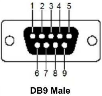 | ||
| 2 RXD | Receive Data | ||
| 3 TXD | Transmit Data | ||
| 4 DTR | Data Terminal Ready | ||
| 5 GND | Signal Ground | ||
| 6 DSR | Data Set Ready | ||
| 7 RTS | Request to Sent | ||
| 8 CTS | Clear to Sent | ||
| 9 N/A None | |||
Transmitter Front RS-232 Port
Pin assignments for the Transmitter's front RS-232 port that is used for connecting to a computer for serial control are given in the table, below:| Pin Assignment | |||
| 1 N/A None | 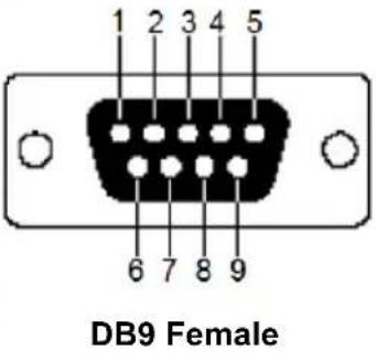 | ||
| 2 TXD Transmit Data | |||
| 3 RXD Receive Data | |||
| 4 DSR Data Set Ready | |||
| 5 GND Signal Ground | |||
| 6 DTR Data Terminal Ready | |||
| 7 CTS Clear to Sent | |||
| 8 RTS Request to Sent | |||
| 9 N/A None | |||
Multicast IP Address
Multicasting helps to broadcast audio and video data from a transmitter to multiple Receivers over a network. To setup up Multicasting on a network switch you must know the Audio and Video Multicast IP address which can be found on the KE Transmitter. To determine the default Multicast IP address set by the KE device use the instructions below. The Multicast IP addresses can be set manually using Telnet.KE Multicast Rule
All Audio and Video Multicast IP addresses use the format: 230.X.Y.Z. X.Y.Z relates to the Transmitter's IP address and 230 is always the first octet of a Multicast IP address. You use the Transmitter's IP address to find X and then use it to calculate the Audio and Video Multicast IP address.Multicast IP Formula
To calculate the Audio and Video Multicast IP address, use the Transmitter's IP address to determine X and then use the appropriate table below to calculate the Multicast IP address for each data stream (audio/video).Example:
Transmitter IP Address: 172.16.27.146; (172.X.Y.Z) X = 16 If X is between 0 \~ 127| Transmitter IP X | VideoX + 128 | AudioX + 192 | MulticastVideo IPAddress | MulticastAudio IPAddress | |
| 172.16.27.146(example) | 16 | 6 ± 128 = 144 | 16 + 192 = 208 | 230.144.27.146 | 230.208.27.146 |
| ____+ 128 = | ____+ 192 = | 230._.._._ | 230._.._._ | ||
| ____+ 128 = | ____+ 192 = | 230._.._._ | 230._.._._ | ||
| ____+ 128 = | ____+ 192 = | 230._.._._ | 230._.._._ |
| Transmitter IP | X - 128 = A | Video A + 128 | Audio A + 192 | Multicast Video IP Address | Multicast Audio IP Address |
| 172.168.27.14 (example) | 168 - 128 = 40 | 40 + 128 = 168 | 40 + 192 = 232 | 230.168.27.14 | 230.232.27.14 |
| ____- 128 = | ____+ 128 = | ____+ 192 = | 230._._._._ | 230._._._._ | |
| ____- 128 = | ____+ 128 = | ____+ 192 = | 230._._._._ | 230._._._._ | |
| ____- 128 = | ____+ 128 = | ____+ 192 = | 230._._._._ | 230._._._._ |
| Transmitter IP | X - 192 = A | Video A + 128 | Audio A + 192 | Multicast Video IP Address | Multicast Audio IP Address |
| 172.200.27.14 (example) | 200 - 192 = 8 | 8 + 128 = 136 | 8 + 192 = 200 | 230.136.27.14 | 230.200.27.14 |
| ____- 192 = | ____+ 128 = | ____+ 192 = | 230._._._._ | 230._._._._ | |
| ____- 192 = | ____+ 128 = | ____+ 192 = | 230._._._._ | 230._._._._ | |
| ____- 192 = | ____+ 128 = | ____+ 192 = | 230._._._._ | 230._._._._ |
Keys to Network Performance
For optimum performance, KE Series devices requires high amounts of data to be transferred across a network; therefore we recommend the following strategies to setup KE Series devices. Using our suggestions will provide better performance and the highest video resolutions possible. Use each of the keys to ensure the best transmission of data and the highest throughput possible.Build a Network Diagram
To build an effective KE installation, start by mapping out the layout. Create a diagram with the KE devices, computers and routers along with how they will be connected across the network. It also helps to write out how the devices will interact. Use this diagram as the frame work as you decide what devices to purchase and how to build the network effectively for the best data throughput.Considerations:
◆ If possible, create a private network for the KE devices ◆ Use the same switch model throughout ◆ Use a flat cascaded layout - Avoid a tree or pyramid structure - Limit cascades to two levels - Install network switches near each other - Minimize the distance of connections - Install KE Matrix Manager (CCKM) computer and KE devices on the same subnet ◆ Check the 3 Other Factors before installationOther Factors
■ Choose the Right Cable
Always use Cat 5/6e Ethernet cable or higher installed by a professional between any two devices you are installing. We recommend using ATEN Brand Ethernet cable to ensure the quality. It's best when installing KE devices to use brand new Ethernet cabling for each part of the installation to ensure the reliability of the data being transmitted. This is a key to getting the best uninterrupted video resolution across the network.■ Determine the Distance
Distance is an important factor when setting up networks, with a shorter distance and fewer hops through routers, data can be transmitted more efficiently. So whenever possible decrease the distance and direct network traffic effectively between subnets that communicate with each other to increase the data throughput.■ Ensure the Bandwidth
Ensuring the bandwidth ahead of time will guarantee performance before installing KE devices on a network. This will eliminate the primary cause of problems related to video quality and transmission of data. If the speed is right at all ends of your network, then the only other causes are derived from device failure or limits caused by a router, switch or device setting. Sample Network Diagram flowchart
graph TD
    subgraph_KE6900T["KE6900T"]
        PC1["PC"] -->|KVM port| KE6900T["KE6900T"]
        KE6900T -->|Console port| KE6900T
    end
    subgraph_KE6900R["KE6900R"]
        KE6900R1["KE6900R"] -->|Console port| KE6900R
        KE6900R -->|Console port| KE6900R
    end
    subgraph_KE6900T["KE6900T"]
        PC2["PC"] -->|KVM port| KE6900T["KE6900T"]
        KE6900T -->|Console port| KE6900T
    end
    subgraph_KE6900R["KE6900R"]
        KE6900R1["KE6900R"] -->|Console port| KE6900R
        KE6900R -->| console port| KE6900R
    end
    subgraph_KE6900T["KE6900T"]
        PC3["PC"] -->|KVM port| KE6900T["KE6900T"]
        KE6900T -->|Console port| KE6900T
    end
    subgraph_KE6900R["KE6900R"]
        KE6900R1["KE6900R"] -->|Console port| KE6900R
        KE6900R -->| Console port| KE6900R
    end
    subgraph_KE6900T["KE6900T"]
        PC4["PC"] -->|KVM port| KE6900T["KE6900T"]
        KE6900T -->|Console port| KE6900T
    end
    subgraph_KE6900R["KE6900R"]
        KE6900R1["KE6900R"] -->|Console port| KE6900R
        KE6900R -->| KVM port | KE6900T
    end
Choose a High Performance Switch
A high performance network switch is the means of a successful KE setup. When choosing a network switch, first select the type:Layer 2 or Layer 3 Switches
You'll need to determine whether you need a layer 2 or a layer 3 switch for your KE network. Layer 3 switches cost more than layer 2 switches because they are more complex and handle more network traffic. The best way to calculate which type of switch you need is to first determine if you will have a dedicated network for the KE devices or if the KE devices will be on a network that shares throughput with other network equipment such as computers, servers and printers. If they share the network with other devices its best to consider a layer 3 switch and use layer 2 switches exclusively for the KE device connections. For larger installations we recommend using Layer 3 switches. The major differences are: Layer 3 Switch: IP addresses in packets are examined and intelligent forwarding decisions are made. On a larger network broken into subnets across long distances, a layer 3 switch becomes the best choice as they can improve network efficiency and provide better traffic flow. They are better at directing more traffic to different locations on a larger more complex network, and with layer two switches working below them. Layer 2 Switch: Packets are examined and forwarded using only the MAC address. If you have a small central network, a layer 2 switch should do the job. If the network is exclusive and will only transmit the bandwidth of KE devices, layer 2 switches with the correct settings can get the job done effectively.Considerations
Number of ports
Choose a switch that has enough ports to match the number of KE devices you will be installing. Switches typically come in 5, 8, 10, 16, 24, 28, 48, and 52-port configurations. If you are installing 13 KE transmitters and 13 KE receivers, you will need to purchase a switch with at least 28 ports.Stackable verse Standalone
Stackable switches allow you to easily manage and configure ports spanning across multiple switches that the KE devices are connected through. This provides a centralized method to configure and troubleshoot the initial setup of KE devices on a network which makes fine tuning the bandwidth, data throughput and video quality easier. Stackable switches can be configured to direct the KE transmissions between many units more specifically and effectively. Standalone switches provide the same configuration features as Stackable switches but they must be set individually. Stackable switches provide an easy way to manage multiple switches, as one unit. For example, instead of configuring, managing, and troubleshooting 6 28-port switches individually, you can manage the six as if they are a single unit using Stackable Switches. The six switches (168 ports) function as a single switch and are managed from one web or GUI interface.What Stackable Switches Can do:
1. Create a link aggregation group with one port in one unit of the stack and another port of that group in another switch in the stack. 2. Select a port on one switch in the stack and mirror the traffic to a switch port on another unit of the stack; thus copy the configuration to direct traffic more effectively between KE devices. 3. Apply custom ACL security settings to any port on any switch in the stack. 4. Stackable switches can be setup in a ring configuration, so that if a port or cable fails, the stack automatically routes around the failure, at microsecond speeds. Stackable Switches also allow you to add and remove stack “members” which are automatically updated and recognized as such.Switch Specifications
The following specifications are recommended when choosing a layer 2 or layer 3 switch: ◆ 1000Mbps Gigabit Ethernet switches (1000Mbps or faster Ethernet ports) ◆ High bandwidth between switches, if possible using Fibre Channel - Layer 3 switches that efficiently processes IGMP queries ♦ IGMP Snooping v2 or v3 ◆ Flow Control Functions ◆ Throughput of: Full Duplex, 1Gbps up- and down- stream speeds per port ◆ Performance of their most onerous tasks (e.g. IGMP snooping) with multiple dedicated processors (ASICS) ◆ Use the same switch make and model throughout each subnet \- The maximum number of simultaneous ‘snoopable groups’ the switch can handle meets or exceeds the number of KE transmitters that will be used to create Channel groupsConfiguring Switches and KE Devices
Configuring the switch correctly will pass data more efficiently, allowing a better stream across the network to each KE device. The following settings will help optimize your network traffic through a switch: ◆ Enable IGMP Snooping on L2 switches ◆ Enable IGMP Querier on the L3 switch - Enable IGMP Fast-Leave on all switches where KE units are directly connected - Enable Spanning Tree Protocol (STP) on all switches and enable Portfast exclusively on switch ports that have KE units connected - Pick an appropriate forwarding mode on all switches. Use Cut-through if available, or Store and Forward (see Recommended Network Switches below)KE transmitter Settings:
- Adjust the KE transmitter settings one at a time, in small intervals, and view the images as you do, so that you can adjust to the positive or negative results and achieve the best quality and bandwidth possible - If the quality of color is important, set the Color Depth to 24 bits (KE69 Series) or 36 bits (KE89 Series) and manually adjust other settings until you are satisfied with the visual appearance - If moving video images are shown frequently, increase the Video Quality setting to the highest level and reduce the Bandwidth Limit and Color Depth setting. - When images on the screen are more often static, increase the Background Refresh and/or the Video Quality settings - Check that all KE units have been updated with the latest firmware versionRecommended Network Switches
Below are the network switches that have passed ATEN's stress tests using the KE Series extenders. Our tests streamed content over a network with a resolution of 1920 x 1200 @60Hz (KE69 Series, KE8900S, KE9900ST); 24 bit color depth and 3840 x 2160 @30Hz (KE8950 and KE8952); 36 bit color depth. ♦ Cisco Catalyst 2960X / Catalyst 2960XR / Catalyst 3750 HP Procurve 2920 ◆ H3C S5120 Huawei S5700 ◆ DLink DGS-1510 Please refer to the FAQ link below on how to select network switches and network switch information collected by ATEN Customer Service Division, where the collected information includes customer's feedback from their actual experience in using and installing the product(s). https://eservice.aten.com/eServiceCx/Common/FAQ/view.do?id=6276Setup CCKM Server IP address on Windows
1. Select Network and Sharing Center and click Change adapter settings. 2. Right-click Local Area Connection and select Properties. 3. In the Local Area Connection Properties window, highlight Internet Protocol Version 4 (TCP/IPv4) then click Properties. 4. Select Use the following IP address and enter in the IP for the CCKM server (e.g. any IP address not in use, and in between 192.168.0.2 and 192.168.0.253)\*, Subnet Mask (e.g. 255.255.255.0), and Default Gateway that corresponds with your network setup. 5. Click OK to change the CCKM server's IP address. Note: Make sure the CCKM server's IP address is not a duplicate to prevent IP address conflict. To connect to the CCKM server via web browser, enter the CCKM IP address and port number (default: 8443). For example, if the CCKM IP address is 192.168.0.10, then enter https://192.168.0.10: 8443. If you have a 2nd NIC, please follow the following steps. 6. Select Network and Sharing Center and click Change adapter settings. 7. Right-click Local Area Connection for the 2nd NIC and select Properties. 8. In the Local Area Connection Properties window, highlight Internet Protocol Version 4 (TCP/IPv4) then click Properties. 9. Select Use the following IP address and enter in the IP of the 2nd subnet for the CCKM server (e.g. any IP address not in use, and in between 192.168.1.2 and 192.168.1.253)\*, Subnet Mask (e.g. 255.255.255.0), and Default Gateway that corresponds with your network setup. 10. Click OK to change the CCKM server's IP address of the 2nd subnet.Limited Warranty
ATEN warrants its hardware in the country of purchase against flaws in materials and workmanship for a Warranty Period of two [2] years (warranty period may vary in certain regions/countries) commencing on the date of original purchase. This warranty period includes the LCD panel of ATENLCD KVM switches. Select products are warranted for an additional year (see A+ Warranty for further details). Cables and accessories are not covered by the Standard Warranty.What is covered by the Limited Hardware Warranty
ATEN will provide a repair service, without charge, during the Warranty Period. If a product is detective, ATEN will, at its discretion, have the option to (1) repair said product with new or repaired components, or (2) replace the entire product with an identical product or with a similar product which fulfills the same function as the defective product. Replaced products assume the warranty of the original product for the remaining period or a period of 90 days, whichever is longer. When the products or components are replaced, the replacing articles shall become customer property and the replaced articles shall become the property of ATEN. To learn more about our warranty policies, please visit our website: http://www.aten.com/global/en/legal/policies/warranty-policy/- EMC Information
- KCC Statement
- User Information
- Online Registration
- Telephone Support
- User Notice
- About This Manual
- Contents
- Chapter 1. Introduction
- Chapter 2.Hardware Setup
- Chapter 3. OSD Operation
- Chapter 4. Software Installation
- Chapter 5.Browser / Telnet Operation
- Chapter 6. System Status
- Chapter 7. System Settings
- Chapter 8.Connections
- Chapter 9.Scheduled Profile
- Chapter 10.Sessions
- Chapter 11. Firmware Upgrade Utility
- Chapter 12.CLI Commands
- Appendix
- Package Contents
- KE6900 / KE6940
- KE6900A / KE6940A
- KE6900ST
- KE6910 / KE6912
- KE6920 / KE6922
- KE8900S
- KE8950 / KE8952
- KE9900ST
- KE9950 / KE9952
- Conventions
- Product Information
- Overview
- Features
- Requirements
- Console
- Computers
- Cables
- Minimum Hardware/Software Requirements
- Components
- KE6900ST (Transmitter) Front, Rear and Top View
- No. Component Description
- PoE Power Redundancy
- Chapter 2
- Hardware Setup
- Mounting
- Attaching the Bracket
- Non-Slim Transmitters
- Slim Transmitters - KE6900ST
- Slim Transmitters - KE8900ST / KE9900ST
- Rack Mount
- Wall Mounting
- KE6900 / KE6940 Point-to-Point Installation
- KE6900 / KE6940 Point-to-Point Installation 2 of 2
- KE6900A / KE6940A Point-to-Point Installation
- KE6900A / KE6940A Point-to-Point Installation 2 of 2
- KE6910 / KE6912 Point-to-Point Installation
- KE6910 / KE6912 Point-to-Point Installation 2 of 2
- KE6920 / KE6922 Point-to-Point Installation
- KE6920 / KE6922 Point-to-Point Installation 2 of 2
- KE8950 / KE8952 Point-to-Point Installation
- KE8950 / KE8952 Point-to-Point Installation 1 of 2
- KE8950 / KE8952 Point-to-Point Installation 2 of 2
- KE6900ST Point-to-Point Installation
- Setting up a LAN Installation
- KE8900S Point-to-Point Installation
- KE9900ST Point-to-Point Installation
- KE9950 / KE9952 Point-to-Point Installation
- KE9950 / KE9952 Point-to-Point Installation 2 of 2
- KE6900 / KE6940 LAN Installation
- KE6900 / KE6940 Network Installation Diagram 2 of 2
- KE6900A / KE6940A LAN Installation
- KE6900A / KE6940A Network Installation Diagram 2 of 2
- KE6910 / KE6912 LAN Installation
- KE6910 / KE6912 Network Installation Diagram 2 of 2
- KE6920 / KE6922 LAN Installation
- KE6920 / KE6922 Network Installation Diagram 2 of 2
- KE8950 / KE8952 LAN Installation
- KE8950 / KE8952 Network Installation Diagram 2 of 2
- KE9950 / KE9952 LAN Installation
- KE9950 / KE9952 Network Installation Diagram 2 of 2
- Network Configuration
- Click Save.
- Exit OSD
- Default IP Addresses
- KE I/O Ports
- LED Display
- Authentication Lock (KE6910 / KE6912 only)
- Invoking the OSD
- Touch Screen Calibration
- OSD Hotkeys
- Microphone Hotkey
- OSD Interface
- Receiver Configuration
- Network
- Properties
- Regular Version
- Slim Version
- System
- Transmitter Configuration
- User Preferences
- Connecting
- Logging in for the First Time
- Connections Page
- Array Mode
- Profile Page
- Push Content
- Pull Content
- Download - Trial Version
- KE Matrix Manager Software Install
- Upgrading Trial Version
- Linux Installation
- Logging In
- The KE Matrix Manager Main Page
- Web Components
- Interactive Display Panel
- Installation Wizard
- Install Wizard
- Assign IP Address.
- Transmitter
- Receiver
- Rename devices automatically.
- Confirm Transmitter information.
- Instant Link
- RS-232 / Telnet
- Telnet
- RS-232
- Configuration Menu
- Main Menu
- Network
- Network Settings
- Properties
- Device Properties
- System
- Chapter 6
- System Status
- Copy & Paste
- Please select the items you want to copy.
- Please select the targets you want to paste.
- Virtual Transmitter
- Create Virtual TX
- Intelligent Dual Video Output Management
- Transmitter Group
- Transmitter Permissions
- Receiver Group
- Video Wall
- Receiver Permissions
- Account
- Users
- Adding Users
- Modifying Users
- Deleting Users
- Groups
- Adding Groups
- Modifying Groups
- Deleting Groups
- Permissions
- Assigning Device Permissions
- Profile
- Adding a Profile
- Adding a Schedule
- Log
- General
- Connection Redundancy (KE6910 / 6912 only)
- ANMS
- Event Destination
- Authentication & Authorization
- FW Upgrade
- Firmware Upgrade Recovery
- Redundancy
- Backup / Restore
- Backup
- Restore
- Certificates
- Private Certificate
- Certificate Signing Request
- Sessions
- Chapter 8
- Connections
- Chapter 10 Sessions
- Chapter 11
- Firmware Upgrade Utility
- Preparation
- Starting the Upgrade
- Upgrade Succeeded
- Chapter 12
- CLI Commands
- Serial Control Protocol Commands
- Configuring the Serial Port
- Device/Profile Commands
- Verification
- Switch Port Command
- Mute Command
- Profile Command
- EDID Command
- Reset Command
- RS-232 Command
- OSD Command
- List Command
- Read Command
- Set Command
- Safety Instructions
- Rack Mounting
- Technical Support
- International
- Specifications
- Optional Rack Mounting
- Dual Rack Mounting
- Transmitter Dual Rack Mounting
- Receiver Dual Rack Mounting
- Single Rack Mounting
- IP Installer
- Trusted Certificates
- Self-Signed Private Certificates
- Examples
- Importing the Files
- Reset All Information
- Default Password Pins
- KE8900SR
- KE8900ST
- ■ KE8950R / KE8952R
- RS-232 Pin Assignments
- Transmitter Front RS-232 Port
- Multicast IP Address
- KE Multicast Rule
- Multicast IP Formula
- Example:
- Keys to Network Performance
- Build a Network Diagram
- Considerations:
- Other Factors
- ■ Choose the Right Cable
- ■ Determine the Distance
- ■ Ensure the Bandwidth
- Choose a High Performance Switch
- Layer 2 or Layer 3 Switches
- Considerations
- Number of ports
- Stackable verse Standalone
- What Stackable Switches Can do:
- Switch Specifications
- Configuring Switches and KE Devices
- KE transmitter Settings:
- Recommended Network Switches
- Setup CCKM Server IP address on Windows
- Limited Warranty
- What is covered by the Limited Hardware Warranty
Brand : ATEN
Model : KE6940AR
Category : Receiver