
M-48 - Uncategorized ROLAND - Free user manual and instructions
Find the device manual for free M-48 ROLAND in PDF.


| Product Type | Personal Monitor Mixer |
| Model | M-48 |
| Brand | Roland |
| Mixer Channels | 40 input channels via REAC |
| Mixer Groups | 16 stereo groups |
| Audio Input | REAC digital audio (up to 40 channels) |
| Audio Output | Headphones (PHONES) and Line Out (LINE OUT) |
| Memory | 16 memories for mixer settings |
| Library | M-48 library for storing/recalling presets |
| Equalizer | 3-band EQ per group (Hi, Mid, Lo) |
| Built-in Effects | Reverb send per group |
| Phantom Power | +48V phantom power controlled via S-4000 RCS |
| Control Software | S-4000 RCS (Windows) for setup and management |
| Connectivity | REAC CAT5e Ethernet, RS-232C for S-4000 RCS |
| Power Supply | External AC adapter (included) |
| Dimensions (approx) | 1U rackmount, depth 200 mm |
| Weight (approx) | 2.5 kg |
| Included Accessories | S-4000 RCS software, USB/serial adapter (if needed) |
| Care Instructions | Wipe with dry cloth; avoid liquids and solvents. |
| Safety | Use only approved CAT5e cables; do not obstruct vents. |
| Spare Parts / Repairability | Contact Roland service center for repairs; no user-serviceable parts inside. |
Frequently Asked Questions - M-48 ROLAND
User questions about M-48 ROLAND
0 question about this device. Answer the ones you know or ask your own.
Ask a new question about this device
Download the instructions for your Uncategorized in PDF format for free! Find your manual M-48 - ROLAND and take your electronic device back in hand. On this page are published all the documents necessary for the use of your device. M-48 by ROLAND.
USER MANUAL M-48 ROLAND
Roland Corporation and its affiliates assume no responsibility for any loss or damage (loss of profits, loss of data or other economical losses) caused by use of this software. This is applicable even in case users were noticed from Roland Corporation and its affiliates about possibility of such losses.
Introduction 5
Introduction ......6
Main features....6
System Requirements....6
Starting and exiting S-4000 RCS....7
Starting S-4000 RCS....7
Exiting S-4000 RCS....7
About S-4000 RCS projects 8
Saving an S-4000 RCS project....8
Opening an S-4000 RCS project file....8
Digital snake system settings 9
Connections with a Digital Snake system ....10
Serial port connections....10
Starting a connection with a Digital Snake system 11
Operations in the S-4000 RCS window ....12
The S-4000 RCS window 12
Editing the channel settings of the Digital Snake system....13
Controller 13
Opening a controller....14
Opening the controller's channel edit panel 14
Locking/unlocking the controller 14
Editing the channel name 14
Turning stereo link on/off....15
Turning +48V phantom power on/off....15
Adjusting the preamp gain....15
Assigning Physical Inputs to Channels (S-4000M) 16
Select sources to be displayed (S-MADI)....16
Setting the S-MADI's configuration 17
Level meter settings....18
Viewing version info for the Digital Snake 19
Using scene memories 20
What are scene memories .... 20
Scene memories....20
Storing channel settings to a scene 21
Recalling channel settings from a scene 21
Editing the name of a scene 21
Associating scene recall with M-48 memory recall.... 21
Editing the S-4000M's Input/Output Settings ....22
Storing Input / Output Setups....22
S-4000M Configuration Window 22
Opening S-4000M Configuration Window 23
Resetting Input / Output Setups (System Reset) 23
Merge Patchbay Operations....24
MERGE View 24
S-4000M Merge Patchbay Window 24
Output Patchbay Operations (S-0808)....26
OUTPUT View....26
S-4000M Output Patchbay Window 26
Splitting Merged Inputs (S-4000M's Split Function)....28
Save/Load the S-4000M Input/Output Setup 30
Managing the M-48 Live Personal Mixer ...... 31
What is the M-48 live personal mixer ....32
40-channel mixer 32
Settings and operations for the 40-channel mixer....32
Two sets of outputs....33
Memory functionality....33
Connecting M-48 units to a Digital Snake system ....34
Connections with an S-1608 system....34
Note when connecting M-48 units (S-1608 system) 34
Note regarding the ordering of M-48 sources....34
Example 1: S-1608 + M-48 (16 sources) 35
Example 2: S-1608 + S-0816 + M-48 (24 sources) 36
Connections with an S-4000 system....37
Note when connecting M-48 units (S-4000 system) 37
Note regarding the ordering of M-48 sources....37
Example 1: S-4000S-4000 + M-48 (40 sources)....38
Example 2: S-4000S-3208 + S-4000H + M-48 (32 sources).... 39
Editing and managing M-48 units....40
Where settings are stored....40
Operations in the M-48 Manager window ....41
The M-48 Manager window....41
Opening the M-48 Manager window....41
Operations in the M-48 List....42
Operations in the M-48 List 43
Selecting a unit....43
Editing the unit name 43
Changing the order of units in the list 43
Muting the output of a unit 43
Disabling memory operations from M-48 Manager (MEMORY SAFE function) 43
Menu operations....44
Copying/pasting all parameters between units.... 44
Copying/pasting specific parameters
between units....44
Saving all data of one or more units
(Saving multiple units in a single operation)....45
Memory operations....45
Storing the memories of all units 45
Recalling the memories of all units 45
Using the Engineer's Monitor function....46
Specifying an Engineer's Monitor unit 46
Viewing version info for the Engineer's Monitor 46
Editing the Engineer's Monitor preference settings 47
Releasing the Engineer's Monitor....47
Note to use the Engineer's Monitor function....47
Operations in the M-48 edit panel ....48
M-48 edit panel 48
Editing the group name 49
Blinking the unit's LEDs....49
Editing when the serial port is not connected (Editing a virtual unit).... 49
Setting the source's LEVEL, PAN, and AUX switch (Source level/pan settings) 50
M-48 Source Lev/Pan window 50
Opening the M-48 Source Lev/Pan window 50
Editing the source level / pan settings 51
Resetting the source level / pan settings....51
Assigning sources to groups (Source assign settings) 52
M-48 Source Assign window....52
Opening the M-48 Source Assign window 52
Making source assignments 53
Clearing the source assign settings....53
Editing the preference settings 54
M-48 Preferences window 54
Opening the M-48 Preferences window 54
Editing the preference settings....54
Resetting the preference settings 55
Viewing and editing a musician's mix (Group mix) 56
Viewing and editing the group mix 56
Editing a group name....57
Resetting the group mix 57
Unit memory operations ....58
M-48 Memory window 58
Opening the M-48 Memory window 58
Storing a memory....58
Recalling a memory 59
Editing the memory name 59
Clearing the contents of a memory....59
Using the M-48 library....60
M-48 Library window....60
Opening the M-48 Library window 60
Storing to the library....60
Recalling from the library 61
Editing the name of a library item....61
Clearing a library item....61
Saving or loading the data of a unit (Saving or loading an M-48 project file) 62
Saving an M-48 project file 62
Loading an M-48 project file....62
Example setups....63
Example setup for Drummer....63
Example setup for lead vocalist....64
Example setup for backing vocalists 65
Appendix.... 67
Messages....68
Introduction
Main features
S-4000 RCS is an application that lets you manage and perform setup of the Digital Snake system from your computer.
The S-4000 RCS enables you to perform management and following setups.
• Editing the channel settings of the Digital Snake system (p. 13).
- Editing the S-4000M's Input/Output Settings (p. 22)
• Managing the M-48 Live Personal Mixer (p. 31)
S-4000 RCS is able to edit and manage up to four Digital Snake systems.
System Requirements
| Operating System | Microsoft® Windows® XP Home Edition SP2 or laterMicrosoft® Windows® XP Professional SP2 or laterMicrosoft® Windows Vista® SP1 or laterMicrosoft® Windows® 7 32-bit EditionMicrosoft® Windows® 7 64-bit Edition* S-4000 RCS does not work with the 64-bit Edition of Windows® XP* S-4000 RCS does not work with the 64-bit Edition of Windows Vista®* S-4000 RCS does not work with Microsoft® Windows® XP Media Center Edition. |
| CPU | Pentium®/Celeron® or compatible processor, 1.6GHz or faster* We cannot make guarantees regarding the compatibility of processors. |
| RAM | 512MB or more |
| Display | 1024 x 768 pixels or higher, 65,536 colors (16-bit color) or higher |
| Interface | Serial Interface (RS-232C D-Sub 9pins)* Check that the serial interface of your computer works properly.<Expansion of serial interface>Connect USB/serial conversion cable or conversion adaptor to your computer and carry out installation to make all the serial interfaces work properly.[Warning]Using a combination of USB/serial conversion cables and conversion adaptors from various manufacturers may make the system unstable. Please do not use this product with such configurations. |
* While under most conditions, a computer similar to the above will permit normal operation of the S-4000 RCS, Roland Corporation and its affiliates cannot guarantee compatibility solely on these factors. This is due to numerous variables that may influence the processing environment, such as differences in motherboard design and the particular combination of other devices involved.
Starting and exiting S-4000 RCS
Starting S-4000 RCS
- In the [S-4000RCS] folder, double-click the [S4000RCS.exe] icon.
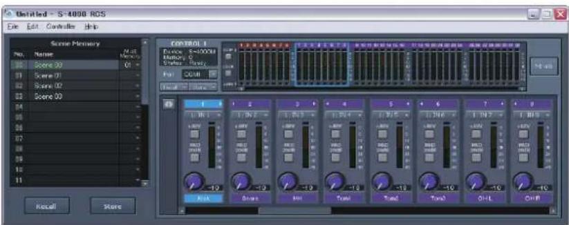
S-4000 RCS will start up, and the S-4000 RCS window will appear.
Exiting S-4000 RCS
- In the S-4000 RCS window, click File > Exit.
S-4000 RCS will close.

If there's been a change in the S-4000 RCS project (p. 8), a message will ask whether you want to save the project before exiting S-4000 RCS.
About S-4000 RCS projects
S-4000 RCS data is called an S-4000 RCS project. An S-4000 RCS project can be saved as an S-4000 RCS project file (extension: .s4r). An S-4000 RCS project contains the following data.
- Channel names of the Digital Snake system
- Serial port selection for controllers 1–4
- Scene memories
• M-48 list order
• M-48 library data
* The following data is not included in an S-4000 RCS project.
• The memory of the Digital Snake system(s)
• The S-4000M's input/output settings
• The memory of the M-48 unit(s)
Saving an S-4000 RCS project
- In the S-4000 RCS window, click File > Save as...
The "Save As" dialog box will appear. - Specify the location and le name for saving the S-4000 RCS project.
- Click the [Save] button.
The S-4000 RCS project file will be saved.
Opening an S-4000 RCS project file
Opening a new S-4000 RCS project le
- In the S-4000 RCS window, click File > New.
A new S-4000 RCS project will open.
Opening an existing S-4000 RCS project le
- In the S-4000 RCS window, click File > Open...
The "Open" dialog box will appear. - Select the desired S-4000 RCS project le and click the [Open] button.
The S-4000 RCS project file will open.

If a change has been made in the S-4000 RCS project file, a message box will ask whether you want to save the project.

If a change has been made in the S-4000 RCS project file, a message box will ask whether you want to save the project.
Digital snake system settings
Serial port connections
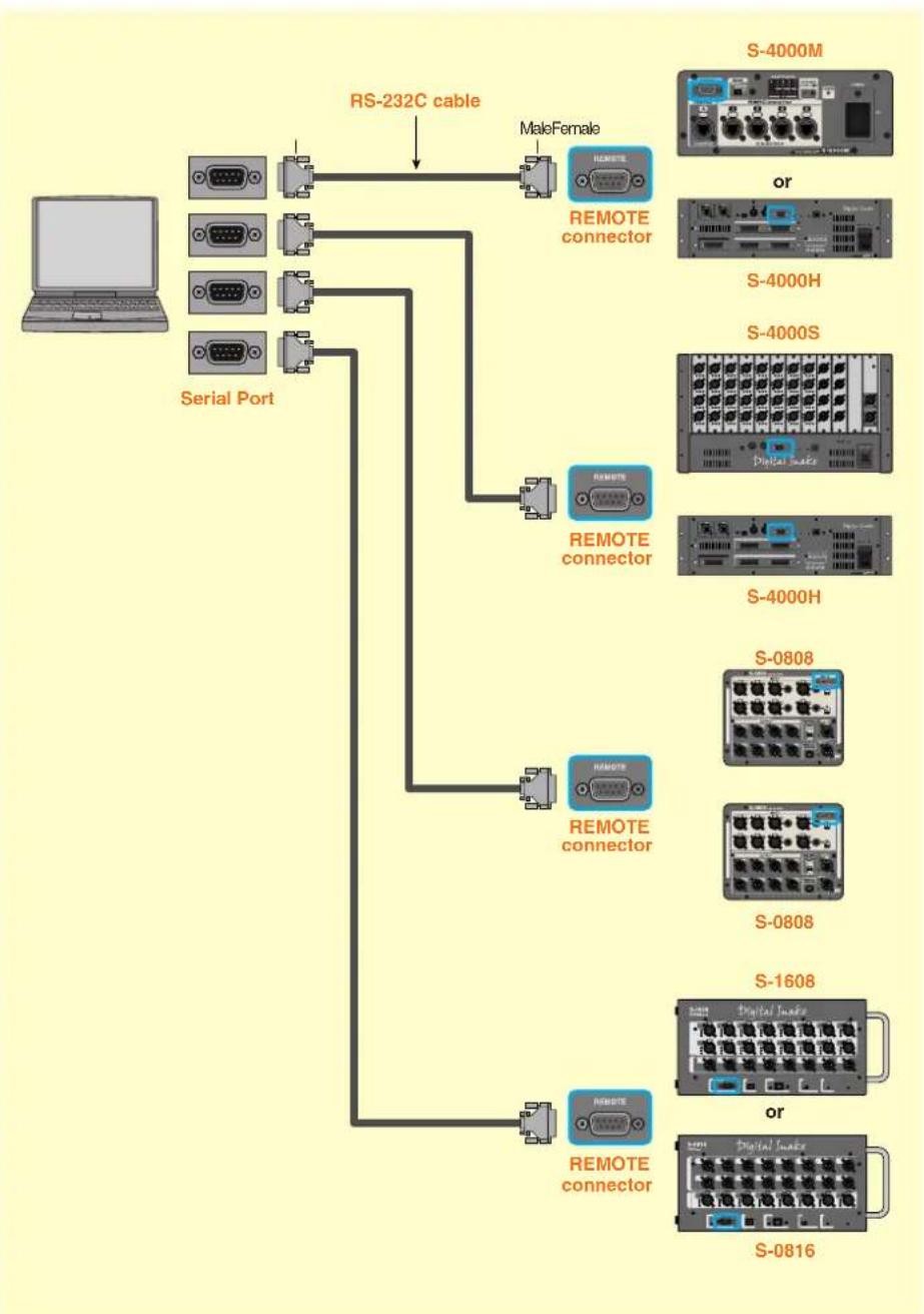
Connect your computer to the Digital Snake systems as shown in the illustration below. You can connect up to four Digital Snake systems to a single computer.
flowchart
graph TD
    A[" Laptop "] --> B[" Serial Port "]
    B --> C[" RS-232C cable "]
    C --> D[" MaleFemale "]
    C --> E[" Remote connector "]
    E --> F[" S-4000M "]
    E --> G[" or "]
    E --> H[" S-4000H "]
    E --> I[" S-4000S "]
    E --> J[" Digital Make "]
    E --> K[" S-4000H "]
    E --> L[" S-0808 "]
    E --> M[" S-0808 "]
    E --> N[" S-1608 "]
    E --> O[" or "]
    E --> P[" S-0816 "]
    E --> Q[" Remote connector "]
Caution for serial connections
* Use the RS-232C cable accessory of the S-4000 Digital Snake system to connect your computer and the S-4000 system. If it's necessary to use longer or shorter cable, please purchase RS-232C cable (D-Sub 9pins/male-female/ straight type).
* It is recommended to use a cable 15 meters in length or shorter.
* For information of REMOTE connector's pin configuration, refer to the owner's manuals for respective products.
Starting a connection with a Digital Snake system
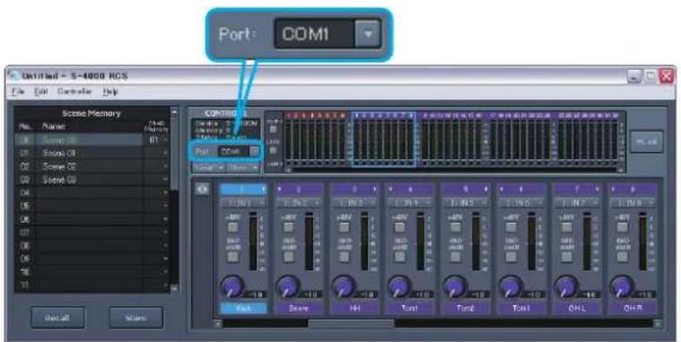
1. In the controller's serial port select box, choose the serial port to which the desired Digital Snake system is connected.
When the connection is established, the current channel settings of the Digital Snake system will be loaded into the controller.
Caution when starting a connection
* Any channel settings that were made for the controller prior to establishing the connection will be discarded. (However, the channel names will remain.) By storing the scene memory before you start the connection, you can save the channel settings to the S-4000 RCS project.
* When you select a serial port, the "Virtual" unit indication (p. 49) in the M-48 Manager window (p. 41) will no longer be shown. By storing the settings of the "Virtual" unit to the M-48 library before you select a serial port, you can save the settings to the S-4000 RCS project.
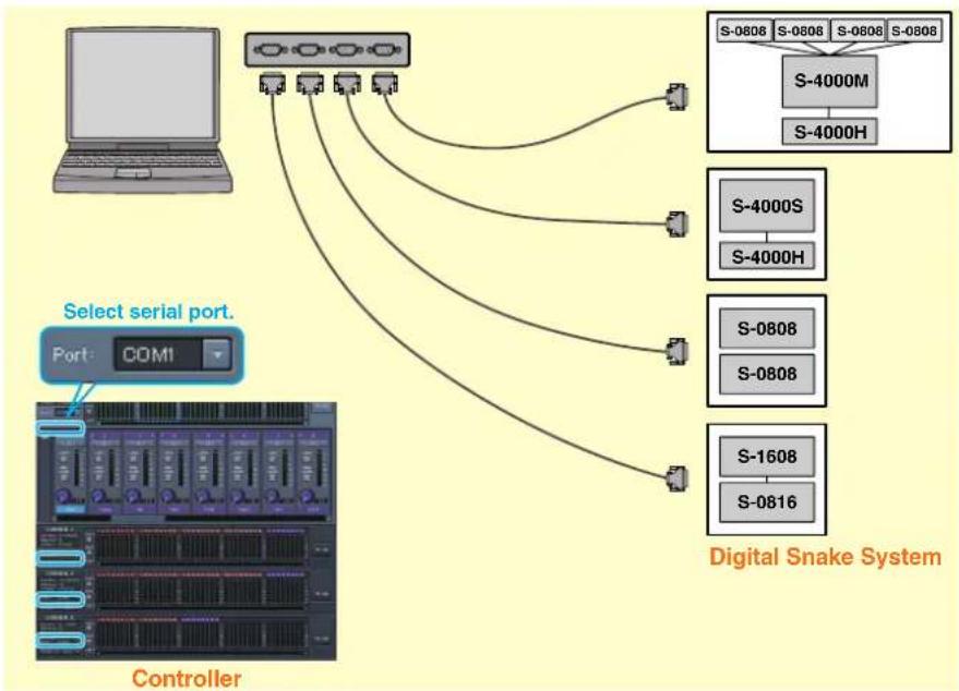
If more than one system is connected
- In the S-4000 RCS window, click Controller > #1—#4 to open a controller.
- Assign each connected Digital Snake system to a controller by selecting the serial port for each controller.
flowchart
graph TD
    A["Client"] --> B["Select serial port"]
    B --> C["Controller"]
    C --> D["S-0806"]
    C --> E["S-0806"]
    C --> F["S-0806"]
    C --> G["S-0806"]
    D --> H["S-4000M"]
    E --> I["S-4000H"]
    F --> J["S-4000S"]
    G --> K["S-4000H"]
    H --> L["S-0808"]
    H --> M["S-0808"]
    I --> N["S-1608"]
    I --> O["S-0816"]
    J --> P["S-4000S"]
    K --> Q["S-4000H"]
MEMO
A single serial port cannot be selected for more than one controller.
The S-4000 RCS window

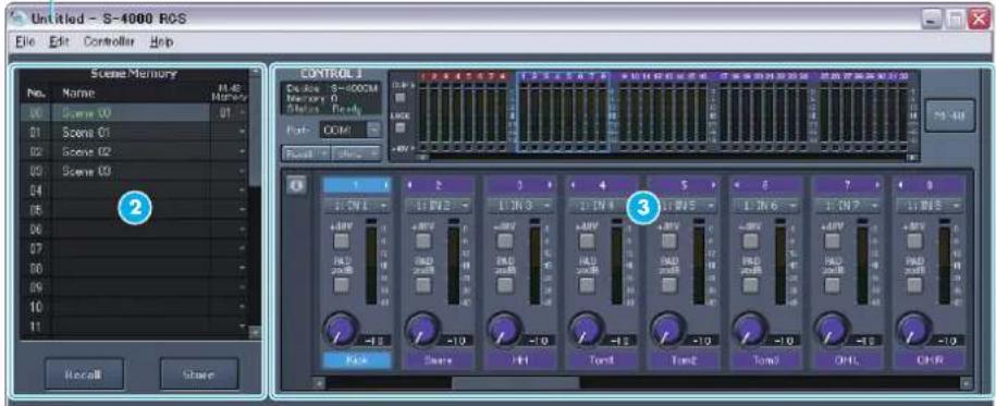
| Item | Name Function | |
| 1 | Project name | Indicates the name of the S-4000 RCS project that is currently open. |
| 2 | Scene memory Here you can perform scene memory operations (p. 20). | |
| 3 | Controller | Here you can edit channel settings for the Digital Snake system (p. 13). |
Menu
| Menu bar | Menu item Function | |
| File | New Creates a new | S-4000 RCS project. |
| Open... Opens an S-4000 RCS project file. | ||
| Save Saves the S-4000 RCS project. | ||
| Save As... Saves the S-4000 RCS project under a different name. | ||
| Exit Quits the S-4000 RCS application. | ||
| Controller | #1 – #4 Opens the controller of the checked number. | |
| Meter Setup... Opens the Meter Setup dialog box (p. 18). | ||
| Clear Clip Clears any lit clip indicators. | ||
| * Updater... | Updates the system program of the Digital Snake. | |
| Help | About S-4000 RCS... | Displays the software version of the S-4000 RCS |
* For steps to update system program, refer to the guidance document provided with the updater.
MEMO
The S-4000 RCS window is the main window of the S-4000 RCS application.
MEMO
If the S-4000 RCS project has been edited, an “*” will be added to the end of the project name.
Editing the channel settings of the Digital Snake system
Controller
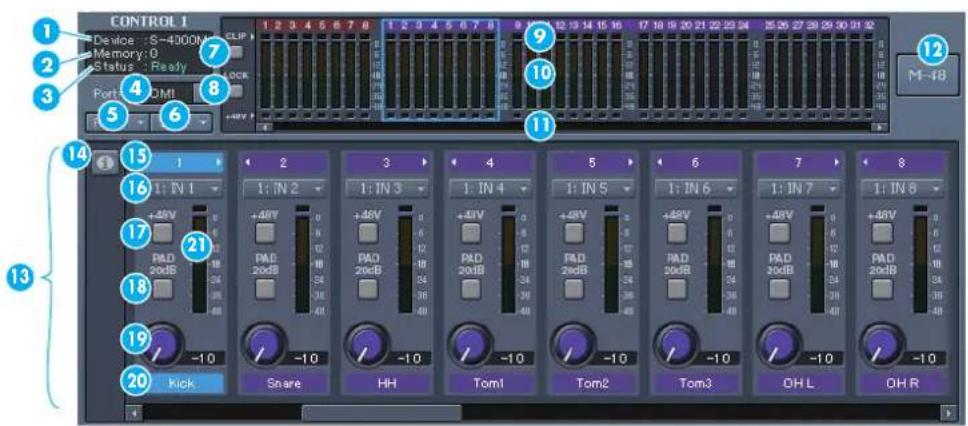
| Item | Name Function | |
| 1 | Device Name | Displays name of the Digital Snake device |
| 2 | Memory number Indicates the currently selected memory number. | |
| 3 | Serial communication indicator | Indicates the status of serial communication between S-4000 RCS and the S-4000 system.Ready: Serial communication is establishedREAC Down: No REAC communication--: No serial communication |
| 4 | Serial port selection box | Selects a serial port. |
| 5 | [Recall] button Recalls | the channel settings of the selected memory. |
| 6 | [Store] button Saves the channel settings in the selected memory. | |
| 7 | [CLIP] button | Click this to clear the clip indicators and peak hold indicators.When a level meter's clip indicator lights, this button will blink red. |
| 8 | [LOCK] button | Locks/unlocks the controller. If the controller is locked, this will be lit or blinking orange. |
| 9 | Channel number | Indicates the channel number.Brown background: Indicates an input of the REAC master device.Purple background: Indicates an input of a REAC slave device. |
| 10 | Level meter | Indicates the input level. You can click this to select a channel. |
| 11 | +48V indicator | Indicates the on/off status of +48V phantom power. When on, this will light red. |
| 12 | [M-48] button Opens the M-48 Manager window (p. 41). | |
| 13 | Channel edit panel In this panel you can edit the channel settings. | |
| 14 | [info] button | Opens the Device Info dialog box (p. 19). |
| 15 | Channel number | Clicking the arrow shown by the channel number will turn stereo link on/off. |
| 16 | Input Select Box | This is valid for the S-4000M REAC MERGE UNIT only. This part displays the physical input number (of the REAC slave device) assigned to the channel. Click here to change the assignment (p. 16). |
| 17 | [+48V] button Turns +48V phantom power on/off. When on, this will light red. | |
| 18 | [PAD] button Turns the pad on/off. When on, this will light orange. | |
MEMO
The serial port selection and the channel names are saved in the S-4000 RCS project.
MEMO
In the input select box, a physical input number is shown in red, if the input does not exist in the system.
| Item | Name Function | |
| 19 | Gain knob Adjusts the | preamp gain. |
| 20 | Channel name | Indicates the channel name. Double-click this to edit the channel name. |
| 21 | Channel level meter | Indicates the input level. |
Opening a controller
- Choose Controller > #1-#4. Click to add a check mark.
The controller will open.
Opening the controller's channel edit panel
If more than one controller is open, the channel edit panel is shown for only one controller.
- Click the desired controller.
The controller's channel edit panel will open.
If S-4000 RCS is connected to a split REAC device, it is only possible to view the channel settings and level meters.
Locking/unlocking the controller
You can lock the controller to prohibit channel settings from being edited. This lets you prevent channel settings from being inadvertently changed.
- Click the [LOCK] button to lock or unlock the controller.
If the controller is locked, the [LOCK] button will light or blink orange.
* If S-4000 RCS (or an S-4000R remote controller) is connected to both the REAC master device and to a REAC slave device, you can unlock only one of the controllers. At this time, the other controller will automatically be locked, and the [LOCK] button will blink.
Storage of channel settings
The channel settings of the Digital Snake system are backed up to the internal memory of the REAC master device approximately every 30 seconds. The backed-up settings will be restored the next time you turn on the power.
If you want to execute a backup immediately, perform the following operation.
- Click the [LOCK] button to switch the lock status.
The channel settings will be backed up to the internal memory of the REAC master device.
Editing the channel name
- Double-click the channel name.
The channel name will be editable.

The channel name is also used as the source name in the M-48 Source Lev/Pan window (p. 50) and the M-48 Source Assign window (p. 52).
Turning stereo link on/off
- Click the arrow beside the channel number to turn stereo link on/off.
Link onLink off
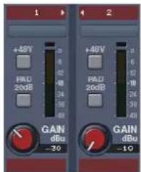
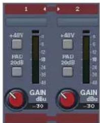
* Pairing is possible only for adjacent odd-numbered/even-numbered channels.
* When you turn stereo link on, the preamp gain and pad settings of the odd-numbered channel will be copied to the even-numbered channel. Even if you then turn stereo link off, the even-numbered channel will not return to its prior state.
* Phantom power can be turned on/off individually even if stereo link is on.
Turning +48V phantom power on/off
- Click the [+48V] button to turn +48V phantom power on/off.
If +48V phantom power is on, the [+48V] button will light red.
Caution when using +48V phantom power
* You must turn phantom power off if a device not requiring phantom power is connected. Malfunctions will occur if phantom power is supplied to a dynamic microphone, audio playback device, or any other device that does not require phantom power. Carefully read the owner's manual included with the microphone or other device you're using, and verify its specifications.
Adjusting the preamp gain
- Drag the gain knob of the desired channel up / down or left / right to adjust the preamp gain.
The gain adjustment range will depend on the state of the [PAD] button.
| [PAD] button | Gain adjustment range |
| Off | -65 --10 dBu |
| On -45 --+10 dBu |
Operations using the keyboard
| Key | Operation |
| [←] ↗ [ | Selects a channel |
| [shift] + [↑/ [ ] → | Selects a channel (in 8-channel steps) |
| [↑] ↘ [ | Increases / decreases the preamp gain (1 dB steps) |
| [shift] + [↑/ [ ] ↓ | Opens the channel edit panel for the controller above or below |
| [L] Turns channel link on/off | |
| [P] Turns PAD on/off | |
| [enter] Edits the channel name | |
MEMO
When you switch the [+48V] button on/off, that channel will be temporarily muted to prevent noise from being produced.
MEMO
When you switch the [PAD] button on/off, that channel will be temporarily muted to prevent noise from being produced.
Assigning Physical Inputs to Channels (S-4000M)
You can assign the physical inputs (of the REAC slave device) to the channels (being sent to the REAC master device).
- Select the physical input number on the input select box of the target channel.
Select REAC slave device first and then select input number.
Select sources to be displayed (S-MADI)
You can select sources to be displayed on the controller.
- Click the REAC IN tab or the MADI IN tab to select the sources to be displayed on the controller connected to the S-MADI.
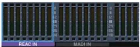
| Tab | Sources to be displayed |
| REAC IN | REAC MAIN input signals |
| MADI IN MADI IN | signals |

You can also change the assignment on the S-4000M Merge Patchbay (p. 24).
Setting the S-MADI's configuration
You can select the sources to be output from the S-MADI's REAC SPLIT OUT connector and the sources to be displayed on an S-4000R connected to the S-MADI.
- Click the [info] button on the controller connected to the S-MADI.
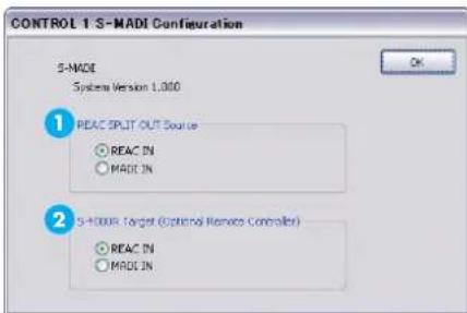
The S-MADI Configuration dialog box will appear.
- Select the sources to be output from the REAC SPLIT OUT connector with REAC SPLIT OUT Source selection button .1
| Selection | Sources output from the REAC SPLIT OUT |
| REAC IN | REAC MAIN input signals |
| MADI IN MADI IN | signals |
- Select the sources to be displayed on the S-4000R with S-4000R target button 2
| Selection | Sources displayed on the S-4000R |
| REAC IN | REAC MAIN input signals |
| MADI IN MADI IN | signals |
- Click the [OK] button.
MEMO
When an S-4000M is connected to the S-MADI's REAC MAIN connector, clicking the [info] button on the controller opens the S-4000M Configuration window (p. 22). You can open the S-MADI Configuration window by clicking the [info] button of the S-MADI on this window.
Level meter settings
You can specify the duration that the clip indicator and peak hold indicator of the level meter will remain lit.
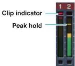
- In the S-4000 RCS window, click Controller > Meter Setup...
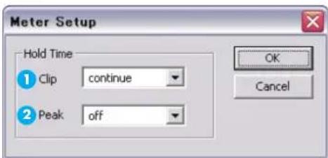
The Meter Setup dialog box will appear.
- In the Clip selection box, specify the duration that the clip indicator is to remain lit.
| Selection | Operation |
| 1sec – 4sec | The clip indicator will remain lit for one to four seconds. After this time has elapsed, the clip indicator will be cleared automatically. |
| continue | The clip indicator will remain lit until you click the [CLIP] button to clear the level meter. |
- In the Peak selection box, specify the duration that the peak indicator is to remain lit.
| Selection Operation | |
| Off | The peak hold indicator will not be shown. |
| 1sec – 4sec | The peak hold indicator will remain lit for one to four seconds. After this time has elapsed, it will be cleared automatically. |
| continue | The peak hold indicator will remain lit until you click the [CLIP] button to clear the level meter. |
- Click the [OK] button.
The level meter settings will be applied.
MEMO
The level meter settings are saved as settings for the application.
MEMO
The level meter settings apply to all meters within S-4000 RCS.
Viewing version info for the Digital Snake
Here's how to view the name and the system program version of the Digital Snake that is directly connected to S-4000 RCS via a serial connection.
- In the channel edit panel of the controller, click the [info] button

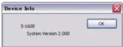
The name and the system program version of the Digital Snake are shown.
When an S-4000M is connected to the controller, clicking the [info] button on the controller opens the S-4000M Configuration window (p. 22). You can check the name and the system program version by clicking the [info] button of the connected devices on the S-4000M Configuration window.
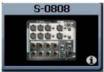
Using scene memories
What are scene memories
The current channel settings of controllers 1–4 can be stored as a scene and recalled when desired. These settings are called "scene memories."
How scene memories are associated with M-48 memories
If an M-48 unit is connected to the Digital Snake system, you can associate scene memories with M-48 memories. An M-48 memory can be stored at the same time that you store a scene, or an M-48 memory can be recalled at the same time that you recall a scene.
Notes regarding scene memories
* Scene memories are saved within the S-4000 RCS project.
* An S-4000 RCS project can contain one hundred scenes.
* Scene memories can be stored and recalled even if a connection has not been established.
* Storage and recall of M-48 memories occurs within the M-48's internal memory.
* If the M-48 is not connected to the system, M-48 memories will not be stored or recalled.
* Scene memories doesn't store/recall the S-4000M's input/output setups (p. 22).
Scene memories
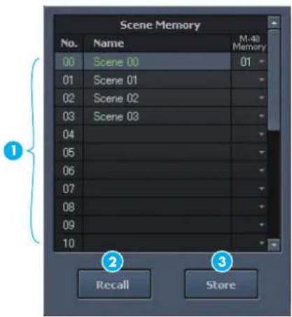
| Item | Name Function | ||
| 1 | Scene list | No. Indicates the scene number. | |
| Name | Indicates the scene name. You can double-click this to edit the scene name. | ||
| M-48 Memory selection box | Selects the M-48 memory number that will be associated with each scene. | ||
| 2 | [Recall] button Recalls the channel settings from the selected scene. | ||
| 3 | [Store] button Stores the channel settings to the selected scene. | ||

The current scene is shown in green.
Storing channel settings to a scene
- Click the desired scene to specify the storage destination.
- Click the [Store] button.
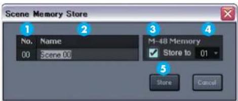
The Scene Memory Store dialog box will appear.
- Verify that the desired scene number is shown.
- Edit the scene name in the scene name edit box .2
If you also want M-48 memories to be stored at the same time, make the following settings.
- In the M-48 Memory area, select the "Store to" check box.
-
In the M-48 Memory area, use the M-48 memory number selection box to select the store-destination memory number.
-
Click the [Store] button .5
The scene will be stored, and the Scene Memory Store dialog box will close.
Recalling channel settings from a scene
- Click the desired scene to select it, and then click the [Recall] button. The scene will be recalled.
Editing the name of a scene
- Double-click the name of the desired scene. The scene name will become editable.
Associating scene recall with M-48 memory recall
- In the M-48 Memory selection box of the desired scene, select the M-48 memory number that you want to associate with the scene. When you recall that scene, the associated M-48 memory will be recalled at the same time. (Units whose MEMORY SAFE function (p. 43) is turned on are excepted.)
MEMO
The scene name can consist of a maximum of 16 single-byte alphanumeric characters.
MEMO
The scene name can consist of a maximum of 16 single-byte alphanumeric characters.
Editing the S-4000M's Input/Output Settings
The S-4000M has a Merge patchbay and an Output patchbay (Output patchbay supports S-0808 8x8 1/O UNITS only). You can edit the S-4000M's Merge/Output patchbays using S-4000 RCS to change input/output assignments.
Merge Patchbay
This merges the inputs of the REAC slave units (REAC ports 1–4) into the channels being sent to the REAC master unit (REAC port A).
Output Patchbay
This assigns the channels being sent from the REAC master unit (REAC port A) to the outputs of the S-0808 units (REAC ports 1–4).
* You cannot edit an S-4000M's input/output settings when the S-4000M is set to the THRU mode.
Storing Input/Output Setups
The S-4000M input/output setup is saved to internal memory. The S-4000M configuration window loads and displays the setup from the connected S-4000M. You can save and load S-4000M input and output setups as a computer file (p. 30)
* S-4000M's input/output setups cannot be saved as part of scene memory.
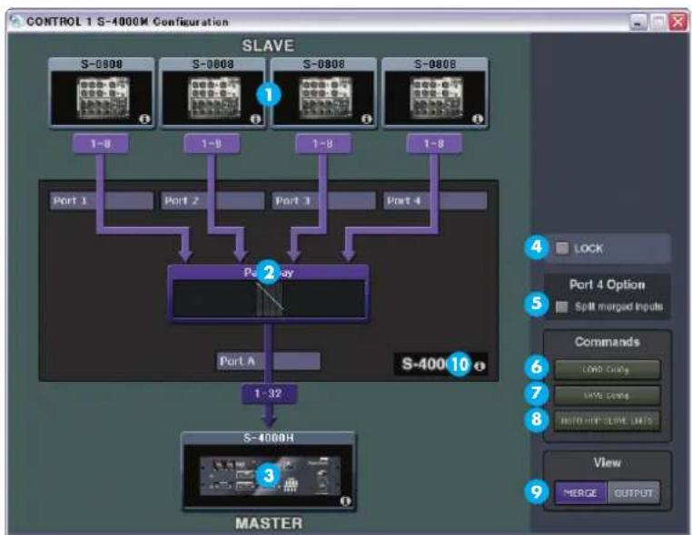
S-4000M Configuration Window
flowchart
graph TD
    A["S-0808"] --> B["1~8"]
    C["S-0809"] --> D["1~8"]
    E["S-0808"] --> F["1~8"]
    G["S-0808"] --> H["1~8"]
    I["Port 1"] --> J["Port 2"]
    K["Port 3"] --> L["Port 4"]
    M["Port A"] --> N["Port A"]
    O["Port A"] --> P["Port A"]
    Q["Port A"] --> R["Port A"]
    S["Port A"] --> T["Port A"]
    U["Port A"] --> V["Port A"]
    W["Port A"] --> X["Port A"]
    Y["Port A"] --> Z["Port A"]
    AA["Port A"] --> AB["Port A"]
    AC["Port A"] --> AD["Port A"]
    AE["Port A"] --> AF["Port A"]
    AG["Port A"] --> AH["Port A"]
    AI["Port A"] --> AJ["Port A"]
    AK["Port A"] --> AL["Port A"]
    AM["Port A"] --> AN["Port A"]
    AO["Port A"] --> AP["Port A"]
    AQ["Port A"] --> AR["Port A"]
    AS["Port A"] --> AT["Port A"]
    AU["Port A"] --> AV["Port A"]
    AW["Port A"] --> AX["Port A"]
    AY["Port 1"] --> Z
    AZ["Port 2"] --> AA
    BA["Port 3"] --> AB
    BB["Port 4"] --> AC
    BC["Port 5"] --> AD
    BE["Port 6"] --> AF
    BF["Port 7"] --> AG
    BG["Port 8"] --> AH
    BH["Port 9"] --> AI
    BI["Port 10"] --> AK
| Item | Name Function | |
| 1 | SLAVE device display | Displays the REAC slave devices connected to REAC ports 1–4. |
| 2 | S-4000M display | Displays how the REAC slave devices are being patched through the REAC master device. |
| 3 | MASTER device display | Displays the REAC master device connected to REAC port A. |
| 4 | LOCK button | Locks/unlocks the operation. If the operation is locked, this will be lit or blinking orange. |
| 5 | Split merged inputs button | Check this button to send the merged inputs, being sent to the REAC master device, to REAC port 4 as well (p. 28). |
| [40950] | [LOAD Config] button | Click here to load an S-4000M input/output setup file (p. 30). |
| [6720] | [SAVE Config] button | Click here to save the S-4000M input/output setup to a file (p. 30). |
| [70882] | [AUTO MAP SLAVE UNITS] button | Click here to reset input/output setup (p. 23) |
| [64524] | View Select button | Click here to select view. You can select MERGE view (p. 24) or OUTPUT view (p. 26). |
| [16443] | [info] buttons [7092] | Click [info] buttons of the SLAVE device display, S-4000M display or MASTER device display to check device name and system version numbers. |
Opening S-4000M Configuration Window
- Click [info] button on the controller connected to S-4000M.
The S-4000M Configuration Window opens.
Resetting Input/Output Setups (System Reset)
You can reset and optimize the merge/output patchbays according to the devices physically connected to REAC ports 1–4.
- Open S-4000M Con guration Window.
- Click [AUTO MAP SLAVE UNITS] button.
The confirmation message box opens to confirm your operation.
- Click [OK].
S-4000M's input/output setup will be reset.
MEMO
The [AUTO MAP SLAVE UNITS] button of S-4000 RCS has the same function as physical button on S-4000M's front panel.
Merge Patchbay Operations
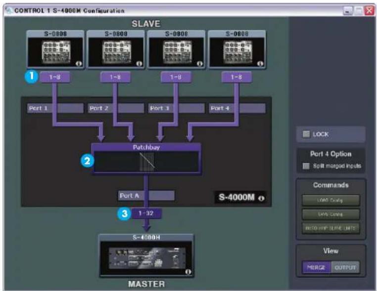
MERGE View
flowchart
graph TD
    A["S-0806"] --> B["1-8"]
    C["S-0808"] --> D["1-8"]
    E["S-0808"] --> F["1-8"]
    G["S-0808"] --> H["1-8"]
    I["Port 1"] --> J["Patchbay"]
    K["Port 2"] --> J
    L["Port 3"] --> J
    M["Port 4"] --> J
    J --> N["Port A"]
    N --> O["1-92"]
    P["S-4000M"] --> Q["S-4000H"]
    Q --> R["MASTER"]
| Item | Name Function | |
| 1 | SLAVE devices inputs | Displays the physical input numbers of the connected REAC slave devices. |
| 2 | Merge Patchbay | Displays overall view of the S-4000M's merge patchbay. Click here to open the S-4000M Merge Patchbay Window. (p. 24) |
| 3 | Channels to MASTER | Displays the number of channels being sent to the REAC master device. |
Switching to MERGE View
- Open the S-4000M Con guration Window
- Click [MERGE] of View Select Button.
You can switch to MERCE View.
S-4000M Merge Patchbay Window
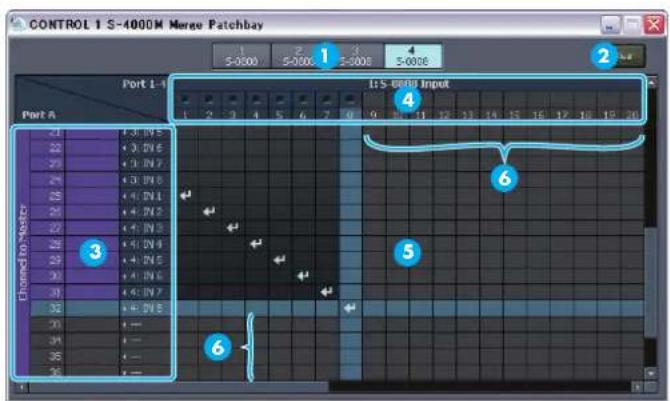
| Item | Name Function | |
| 1 | REAC Port Select Buttons | Click to select the REAC port. |
| 2 | [Clear] button Click to | clear all assignments of currently selected REAC port. |
| 3 | Port A Channel display | Displays channel numbers, names and the currently assigned physical inputs. |
| 4 | Input display | Displays physical input number of current REAC port and signal level. |
| 5 | Patchbay Grid | Icon appears at the cross point of channel (vertical) and physical input (horizontal). |
| 6 | Invalid Area | The following areas are displayed in lighter gray:• The input area where the REAC slave devices cannot be used.• The channel area where the REAC master device cannot be used. |
The following colors represent corresponding signal levels:
| Color | Signal Level |
| Yellow | -18dB or higher |
| Green | -48dB or higher, lower than -18dB |
| Black | lower than -48dB |
Opening the S-4000M Merge Patchbay window
- Open the S-4000M Con guration window.
- Switch to MERGE view.
- Click Merge Patchbay.
The S-4000M Merge Patchbay window opens.
Making assignment in the S-4000M Merge Patchbay
- Open the S-4000M Merge Patchbay window.
- Select the REAC port to display by clicking a speci c REAC Port button.
- Click the intersection of the target channel and physical input number.
An icon appears at the intersection and the assignment of the input is changed.
Clearing All Assignments
- Open the S-4000M Merge Patchbay window.
- Select the target REAC port by clicking a speci c REAC Port button.
- Click [Clear] button
A confirmation message box opens to confirm your operation. - Click [OK]
All assignments associated with the REAC port selected in a step 2 are cleared.
Output Patchbay Operations (S-0808)
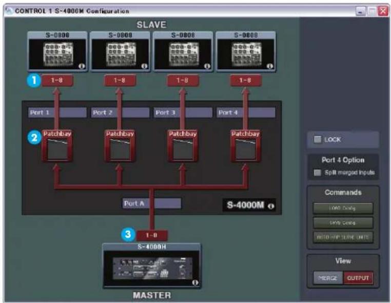
OUTPUT View
flowchart
graph TD
    subgraph Slave
        S008["S-0008"] --> Port1["Port 1"]
        S009["S-0009"] --> Port2["Port 2"]
        S008 --> Port3["Port 3"]
        S008 --> Port4["Port 4"]
    end
    subgraph Master
        S4000H["S-4000H"]
    end
    S4000H -->|1-8| PatchBay1["Patchbay"]
    S4000H -->|1-8| PatchBay2["Patchbay"]
    S4000H -->|1-8| PatchBay3["Patchbay"]
    S4000H -->|1-8| PatchBay4["Patchbay"]
    S4000H -->|1-8| PortA["Port A"]
    PortA -->|1-8| Port1
    PortA -->|1-8| Port2
    PortA -->|1-8| Port3
    PortA -->|1-8| Port4
    PortA -->|1-8| Port1
    PortA -->|1-8| Port2
    PortA -->|1-8| Port3
    PortA -->|1-8| Port4
    PortA -->|1-8| Port1
| Item | Name Function | |
| 1 | SLAVE devices outputs | Displays the available physical output numbers of the connected REAC slave devises. |
| 2 | Output Patchbay | Displays the overall view of the S-4000M's output patchbay. Click here to open the S-4000M Output Patchbay Window.(p. 26) |
| 3 | Channels from Master | Displays the number of output channels being sent from the REAC master device. |
Switching to OUTPUT View
- Open the S-4000M Con guration Window.
- Click [OUTPUT] of View Select Button.
Display is changed to OUTPUT View.
S-4000M Output Patchbay Window
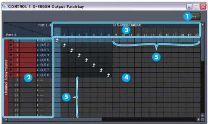
| Item | Name Function | |
| 1 | [Clear] button | Click to clear all assignment |
| 2 | Port A channel display | Displays signal levels, channel numbers, names and the currently assigned physical outputs. |
| 3 | Output display | Displays physical output number on connected REAC slave devices. |
| error | Patchbay Grid | Icon ↑ears at the intersection of channel (vertical) and physical output (horizontal). |
| error | Invalid Area | The following areas are displayed in lighter gray:• The output area where the REAC slave devices cannot be used.• The channel area where the REAC master devices cannot be used. |
The following colors represent corresponding signal levels:
| Color | Signal Level |
| Red | 0dB or higher |
| Yellow | -18dB or higher, lower than 0dB |
| Green | -48dB or higher, lower than -18dB |
| Black | lower than -48dB |
Opening the S-4000M Output Patchbay window
- Open the S-4000M Con guration Window.
- Switch to OUTPUT view.
- Click target output patchbay.
S-4000M's output patchbay opens.
Making assignments in the S-4000M's Output Patchbay window
- Open target window of the S-4000M output patchbay.
- Click the intersection of target channel and physical output number.
An icon ↑fears at the intersection and the assignment of output channel is changed.
Clearing All Assignments
- Open the S-4000M Output Patchbay Window.
- Click [Clear] button.
A confirmation message box opens to confirm the operation.
- Click [OK]
All assignments are cleared.
MEMO
When “...” is displayed at the end of currently assigned output, it means same output channel is coming out from multiple physical outputs.
Splitting Merged Inputs (S-4000M's Split Function)
By using the S-4000M's Split Function, you can split the merged inputs (being sent to the REAC master device) to REAC port 4. It is very convenient when splitting to a monitor console or a multi-channel recording system.
* When a REAC splitter (like the S-4000D) is connected to the S-4000M's REAC port A, the signal from the REAC master device is split.
REAC Split devices REAC Slave devices
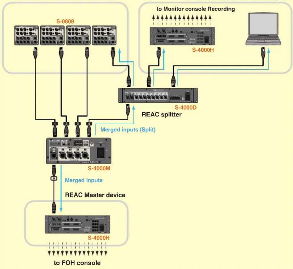
flowchart
graph TD
    A["S-0808"] -->|Merged inputs| B["S-4000M"]
    B -->|Merged inputs (Split)| C["REAC Splitter"]
    C -->|Merged inputs| D["S-4000H"]
    D --> E["to FOH console"]
    F["S-4000H"] -->|Merged inputs| C
    G["S-4000D"] -->|Merged inputs| C
    H["to Monitor console Recording"] -->|Merged inputs| C
    I["Laptop"] -->|Merged inputs| C
Notes About the S-4000M's Split Function
* You can connect a REAC slave device to S-4000M's REAC port 4 via a REAC splitter (like the S-4000D). In this case, the physical inputs of the REAC slave device operate normally but all merged inputs being sent to the Master will being sent out from the physical outputs.
* If an M-48 is connected to the S-4000M's REAC port4, it is not possible to manage/setup the M-48 from the M-48 Manager window.
When a REAC splitter (like the S-4000D) is connected to the S-4000M's REAC port A, the signal from the REAC master device is split.
Using S-4000M's Split Function
- Open the S-4000M Con guration window.
If the "Split merged inputs" button is checked, then the S-4000M's split function is already turned on. The following steps will not be necessary.
-
Disconnect the REAC cable connected to REAC port 4 on the S-4000M.
-
Click "Split merged inputs"
A confirmation message box opens to confirm the operation.
- Click [OK]
The display mode of S-4000M changes. The signal of merged input channels are split and sent out the device connected to REAC port 4.
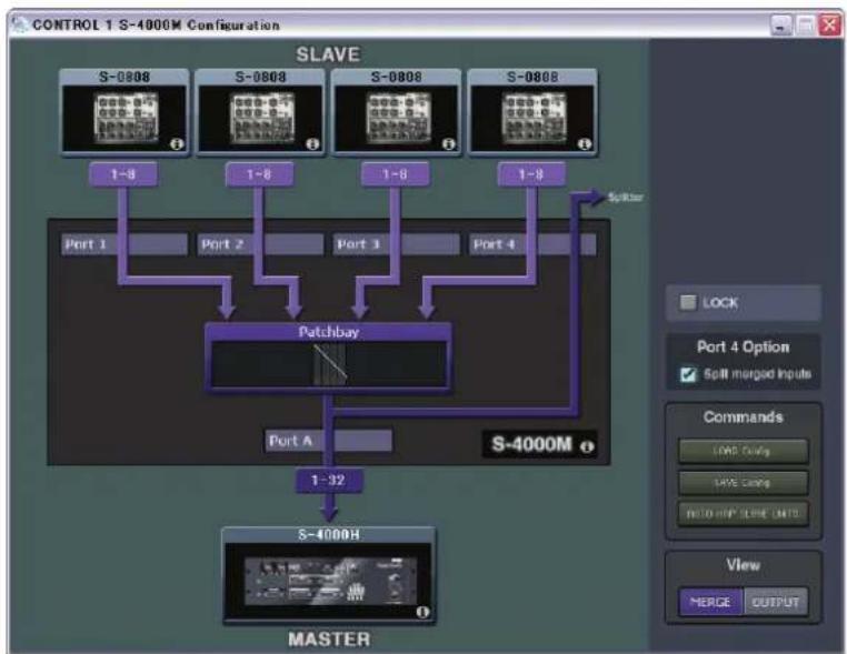
flowchart
graph TD
    A["S-0808"] --> B["1~8"]
    C["S-0808"] --> D["1~8"]
    E["S-0808"] --> F["1~8"]
    G["S-0808"] --> H["1~8"]
    I["Port 1"] --> J["Patchbay"]
    K["Port 2"] --> J
    L["Port 3"] --> J
    M["Port 4"] --> J
    J --> N["Master"]
    O["1~32"] --> P["S-4000H"]
    Q["1~32"] --> R["S-4000M"]
    S["1~32"] --> T["Master"]
    U["1~32"] --> V["S-4000M"]
    W["1~32"] --> X["S-4000M"]
    Y["1~32"] --> Z["S-4000M"]
    AA["1~32"] --> AB["S-4000M"]
    AC["1~32"] --> AD["S-4000M"]
    AE["1~32"] --> AF["S-4000M"]
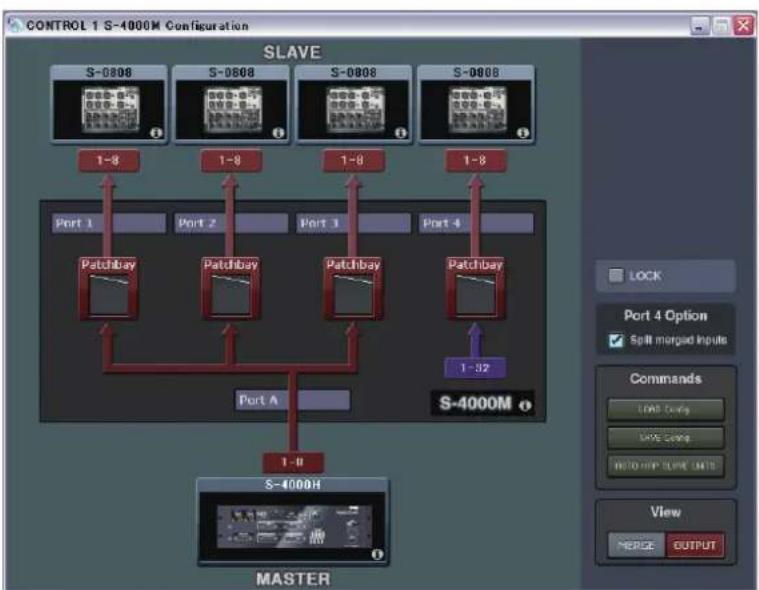
flowchart
graph TD
    subgraph_Slave["SLAVE"]
        S0808["S-0808"] -->|1-8| Port1["Port 1"]
        S0808 -->|1-8| Port2["Port 2"]
        S0808 -->|1-8| Port3["Port 3"]
        S0808 -->|1-8| Port4["Port 4"]
        S0808 -->|1-8| Port5["Port 5"]
        S0808 -->|1-8| Port6["Port 6"]
        S0808 -->|1-8| Port7["Port 7"]
        S0808 -->|1-8| Port8["Port 8"]
        S0808 -->|1-8| Port9["Port 9"]
        S0808 -->|1-8| PortA["Port A"]
        S0808 -->|1-8| PortB["Port B"]
        S0808 -->|1-8| PortC["Port C"]
        S0808 -->|1-8| PortD["Port D"]
        S0808 -->|1-8| PortE["Port E"]
        S0808 -->|1-8| PortF["Port F"]
        S0808 -->|1-8| PortG["Port G"]
        S0808 -->|1-8| PortH["Port H"]
        S0808 -->|1-8| PortI["Port I"]
        S0808 -->|1-8| PortJ["Port J"]
        S0808 -->|1-8| PortK["Port K"]
        S0808 -->|1-8| PortL["Port L"]
        S0808 -->|1-8| PortM["Port M"]
        S0808 -->|1-8| PortN["Port N"]
        S0808 -->|1-8| PortO["Port O"]
        S0808 -->|1-8| PortP["Port P"]
        S0808 -->|1-8| PortQ["Port Q"]
        S0808 -->|1-8| PortR["Port R"]
        S0808 -->|1-8| PortS["Port S"]
        S0808 -->|1-8| PortT["Port T"]
        S0808 -->|1-8| PortU["Port U"]
        S0808 -->|1-8| PortV["Port V"]
        S0808 -->|1-8| PortW["Port W"]
        S0808 -->|1-8| PortX["Port X"]
        S0808 -->|1-8| PortY["Port Y"]
        S0808 -->|1-8| PortZ["Port Z"]
        S0808 -->|1-8| PortW
    end
    subgraph_MASTER["MASTER"]
        S4000H["S-4000H"]
    end
- Connect the REAC cable to REAC port 4 on the S-4000M.
Save/Load the S-4000M Input/Output Setup
Saving the S-4000M Input/Output Setup as Computer File
- Open S-4000M Configuration window.
- Click [SAVE config] button.
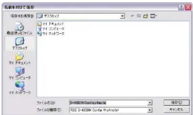
[Save As] dialog appears.
- Specify save destination folder and le name.
- Click [SAVE] button.
Saving is completed when "Complete" message is displayed. Click [OK] to close the message dialog.
Loading the S-4000M Input/Output Setup File
- Open S-4000M Con guration window.
- Click [LOAD con g] button.
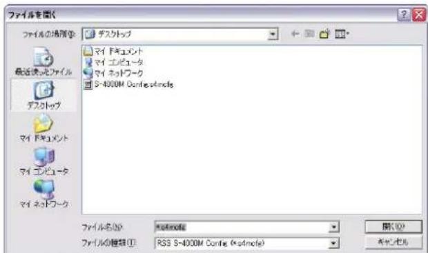
[Open File] dialog appears.
- Specify the le of S-4000M's input/output setup to load.
- Click [OPEN] button.
Managing the M-48 Live Personal Mixer
What is the M-48 live personal mixer
The M-48 is a live personal mixer that allows each musician to create their own mix. By unifying the professional monitor mix created by the mixing engineer with the personal mix created by each musician, the M-48 provides a monitoring environment that's ideal for the musician.
40-channel mixer
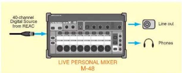
The M-48 provides a REAC port that is able to receive up to 40 channels of digital audio via REAC. The digital audio sources are mixed by the internal 40-channel mixer for monitoring via headphones or monitor speakers.
Settings and operations for the 40-channel mixer
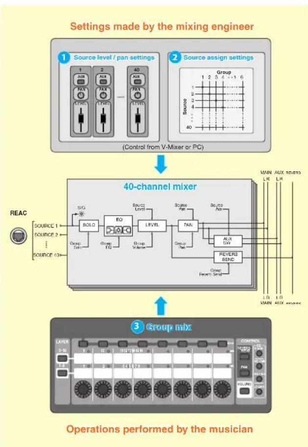
flowchart
graph TD
    A["1 Source level / pan settings"] --> B["(Control from V-Mixer or PC)"]
    C["2 Source assign settings"] --> D["40-channel mixer"]
    E["3 Group mix"] --> F["Operations performed by the musician"]

    subgraph Settings made by the mixing engineer
        G["1 AUX LEVEL 1 2 3 4 5 6 7 8 9 10 11 12 13 14 15 16 17 18 19 20 21 22 23 24 25 26 27 28 29 30 31 32 33 34 35 36 37 38 39 40"]
    end

    subgraph Group
        G1["Group 1 2 3 4 ... 6"]
        G2["Group 2"]
        G3["Group"]
        G4["Group"]
        G5["Group"]
        G6["Group"]
        G7["Group"]
        G8["Group"]
        G9["Group"]
        G10["Group"]
        G11["Group"]
        G12["Group"]
        G13["Group"]
        G14["Group"]
        G15["Group"]
        G16["Group"]
        G17["Group"]
        G18["Group"]
        G19["Group"]
        G20["Group"]
        G21["Group"]
        G22["Group"]
        G23["Group"]
        G24["Group"]
        G25["Group"]
        G26["Group"]
        G27["Group"]
        G28["Group"]
        G29["Group"]
        G30["Group"]
        G31["Group"]
        G32["Group"]
        G33["Group"]
        G34["Group"]
        G35["Group"]
        G36["Group"]
        G37["Group"]
        G38["Group"]
        G39["Group"]
        G40["Group"]
    end
The sources 1–40 being input via REAC are mixed by the M-48's 40-channel mixer. Settings and operation of the 40-channel mixer are shared between the mixing engineer and the musician.
* The 40 digital audio source channels being input via REAC to the M-48 are referred to as sources 1–40.
Settings by the mixing engineer
These settings are made by the mixing engineer from the V-Mixer or the PC.
1 Source level / pan settings
These settings specify the LEVEL, PAN, and AUX switch settings for sources 1–40.
2 Source assign settings
These settings assign sources 1–40 to sixteen stereo groups for operation on the M-48.
Operations performed by the musician
These operations are performed by the musician on the M-48 unit.
3 Group mix
VOLUME, PAN, REVERB SEND, and 3-BAND EQ can be adjusted for each stereo group created by the source assign settings.
* The group mix can also be viewed and edited from the V-Mixer or PC.
Two sets of outputs
flowchart
graph TD
    A["AMBIENT MLC"] --> B["A/U"]
    C["AUX IN"] --> D["A/T"]
    E["AUX IN"] --> F["AUX IN"]
    G["MAIN AUX L/R"] --> H["REVERS"]
    I["REVERS UNIT"] --> J["REVER"]
    K["PHONES OUT"] --> L["EASS TICLE UOUTER VOLUME MUTE"]
    L --> M["METER"]
    M --> N["D/A"]
    O["LINE OUT"] --> P["SOURCE SELBOT LOW PASS VOLUME VOLUME MUTE MONO"]
    P --> Q["D/A"]
    R["L/R"] --> S["REC"]
    T["ATT MAX 524"] --> N
    U["1"] --> N
    V["2"] --> N
    W["3"] --> N
    X["4"] --> N
    Y["5"] --> N
    Z["6"] --> N
    AA["7"] --> N
    AB["8"] --> N
    AC["9"] --> N
    AD["10"] --> N
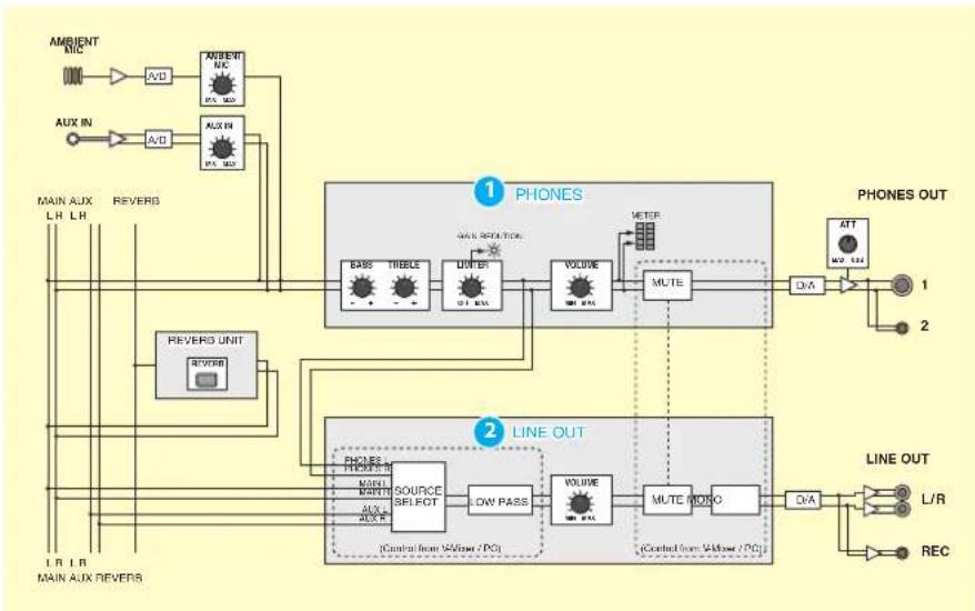
The M-48 provides two sets of output: PHONES and LINE OUT.
1 PHONES
REVERB, AMBIENT MIC, and AUX IN are mixed into the MAIN bus, then BASS, TREBLE, and LIMITER are applied to the mix which is then output from these ports. This is used for headphones or in-ear monitoring.
2 LINE OUT
As the LINE OUT source, you can choose either PHONES (the signal immediately before PHONES VOLUME), MAIN bus, or AUX bus. This is used for a floor monitor or for two-channel recording. Since a low-pass filter is provided on LINE OUT, it can also be used to output just the low frequency range to a floor monitor or tactile transducer.
Memory functionality
The M-48 has 16 memories, and allows mixer settings to be stored or recalled. Memories 1–16 can be manipulated from the M-48 itself or from the V-Mixer or PC.
Connections with an S-1608 system
Note when connecting M-48 units (S-1608 system)
* The S-1608 system must be using system software version 2.0 or later.
If S-4000 RCS is connected to an S-1608/S-0816 that is operating as a split REAC device, it will not be possible to make M-48 settings.
* Up to four S-4000D units can be connected in series. Approximately 200 microseconds of propagation delay will occur for each unit.
* Up to sixty-four M-48 units can be connected to each Digital Snake system.
* In order to maintain the transmission quality of the digital REAC signal, use fully approved CAT5e Ethernet cable such as the 20 meter or 100 meter REAC cables (SC-W20F / SC-W100S / W100S-R; sold separately).
Note regarding the ordering of M-48 sources
The order in which channels are shown for controllers in the S-4000 RCS window may differ from the order of the M-48 sources.
S-4000 RCS window
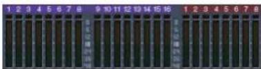
M-48 Source Lev/Pan window
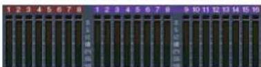
This occurs because the REAC master device and REAC slave device handle channels in a different way than a split REAC device (M-48) handles channels.
On an S-1608 system, this discrepancy will occur in the following case.
- When the S-0816 is the REAC master device

To check the version, refer to "Viewing version info for the Digital Snake" (p. 19).
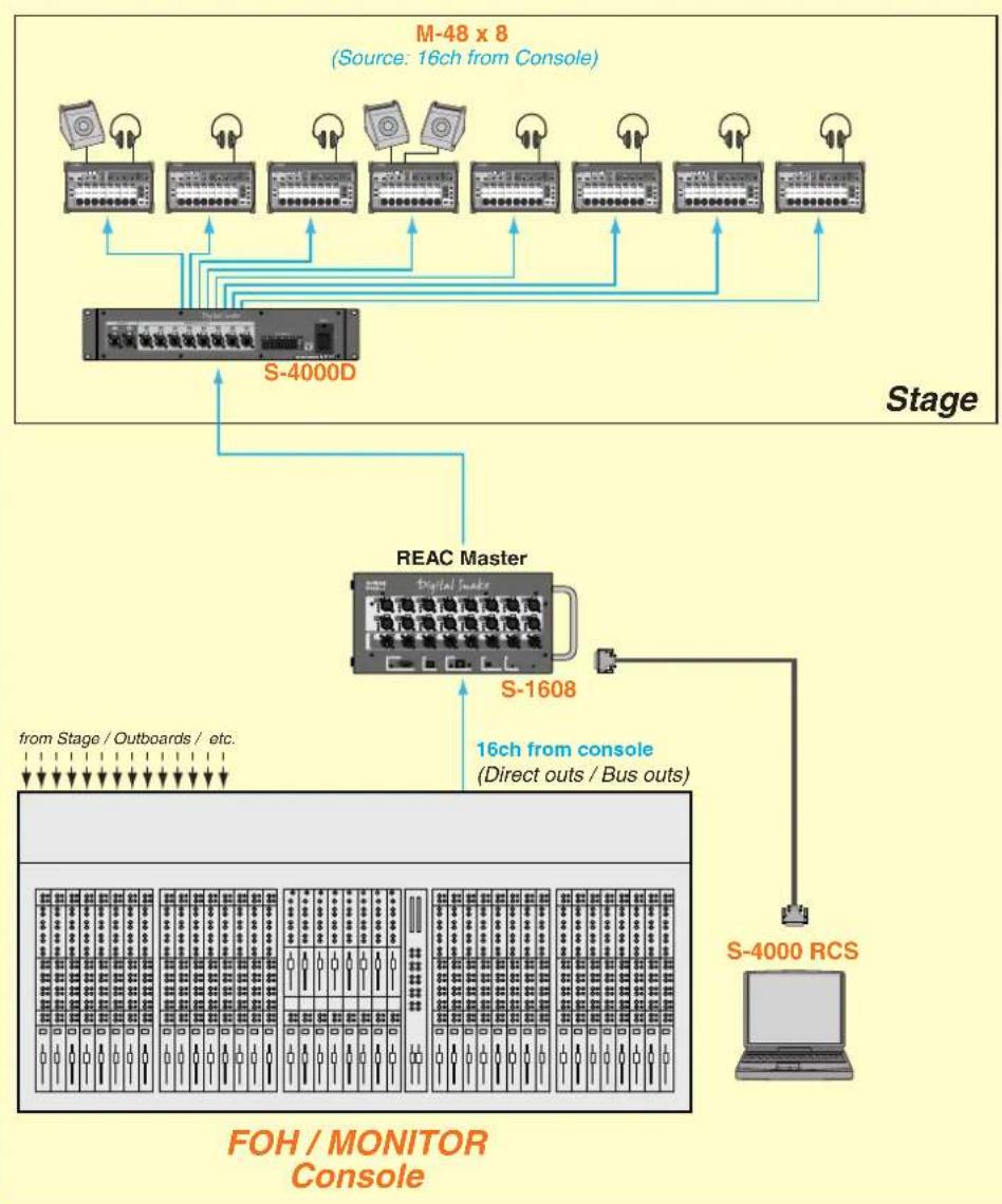
Example 1: S-1608 + M-48 (16 sources)
This is an example in which M-48 units are connected to the S-1608 (REAC master). A total of up to sixteen channels of direct out and bus out signals from the console can be input.
flowchart
graph TD
    A["FOH / MONITOR Console"] --> B["REAC Master"]
    B --> C["S-1608"]
    C --> D["S-4000D"]
    D --> E["M-48 x 8 (Source: 16ch from Console)"]
    B --> F["S-4000 RCS"]
    style A fill:#f9f,stroke:#333
    style B fill:#ccf,stroke:#333
    style C fill:#cfc,stroke:#333
    style D fill:#fcc,stroke:#333
    style E fill:#ffc,stroke:#333

In this example, the S-1608's
OUTPUT 1–8 cannot be used.
Example 2: S-1608 + S-0816 + M-48 (24 sources)
This is an example in which M-48 units are connected between a connected S-1608 (REAC master) and S-0816 (REAC slave). With sixteen channels from the stage and eight channels from the console, this makes a total of twenty-four channels as the sources for the M-48 units.
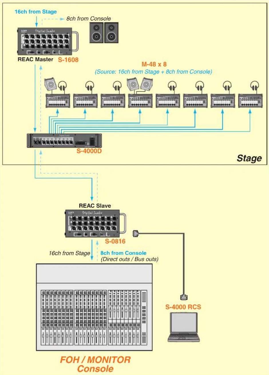
flowchart
graph TD
    A["REAC Master S-1608"] -->|16ch from Stage| B["FOH/MONITOR Console"]
    A -->|8ch from Console| C["S-4000D"]
    C --> D["REAC Slave S-0816"]
    D -->|16ch from Stage| E["FOH/MONITOR Console"]
    D -->|8ch from Console (Direct outs / Bus outs)| F["S-4000 RCS"]
    style A fill:#f9f,stroke:#333
    style B fill:#ccf,stroke:#333
    style C fill:#cfc,stroke:#333
    style D fill:#fcc,stroke:#333
    style E fill:#ffc,stroke:#333
    style F fill:#fcc,stroke:#333
Connections with an S-4000 system
Note when connecting M-48 units (S-4000 system)
* The S-4000 system must be using system software version 2.1 or later.
* If S-4000 RCS is connected to an S-4000S/S-4000H that is operating as a split REAC device, it will not be possible to make M-48 settings.
* Up to four S-4000D units can be connected in series. Approximately 200 microseconds of propagation delay will occur for each unit.
* Up to sixty-four M-48 units can be connected to each Digital Snake system.
* In order to maintain the transmission quality of the digital REAC signal, use fully approved CAT5e Ethernet cable such as the 20 meter or 100 meter REAC cables (SC-W20F / SC-W100S / W100S-R; sold separately).
Note regarding the ordering of M-48 sources
The order in which channels are shown for controllers in the S-4000 RCS window may differ from the order of the M-48 sources.
S-4000 RCS window

M-48 Source Lev/Pan window

This occurs because the REAC master device and REAC slave device handle channels in a different way than a split REAC device (M-48) handles channels.
On an S-4000 system, this discrepancy will occur in the following cases.
- When the S-4000H is the REAC master device
- When the S-4000S is the REAC master device and an output module (e.g., SO-DA4 or SO-AES4) is installed in slot 1 of the S-4000S

To check the version, refer to "Viewing version info for the Digital Snake" (p. 19).
Example 1: S-4000S-4000 + M-48 (40 sources)
This is an example in which M-48 units are connected to an S-4000S-4000 (REAC master). A total of up to forty channels of direct out or bus out signals from the console can be input.
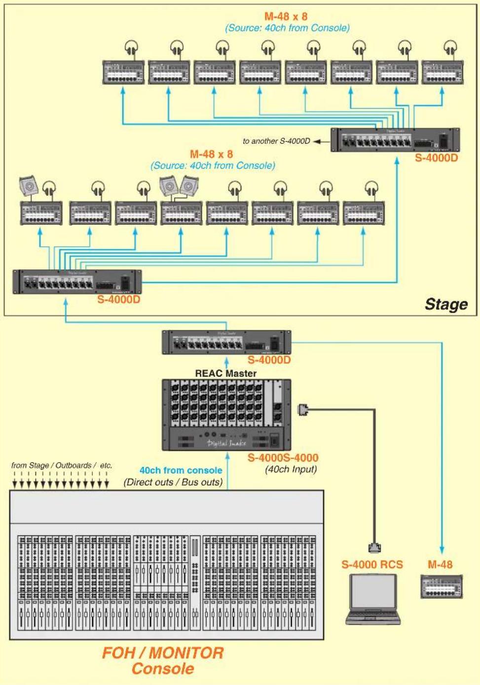
flowchart
graph TD
    subgraph_FOH_MONITOR_Comsole["FOH / MONITOR Console"]
        A1[" "] -->|from Stage / Outboards / etc.| B1[" "]
        A2[" "] -->|from Stage / Outboards / etc.| B2[" "]
        A3[" "] -->|from Stage / Outboards / etc.| B3[" "]
        A4[" "] -->|from Stage / Outboards / etc.| B4[" "]
        A5[" "] -->|from Stage / Outboards / etc.| B5[" "]
        A6[" "] -->|from Stage / Outboards / etc.| B6[" "]
        A7[" "] -->|from Stage / Outboards / etc.| B7[" "]
        A8[" "] -->|from Stage / Outboards / etc.| B8[" "]
        A9[" "] -->|from Stage / Outboards / etc.| B9[" "]
        A10[" "] -->|from Stage / Outboards / etc.| B10[" "]
        A11[" "] -->|from Stage / Outboards / etc.| B11[" "]
        A12[" "] -->|from Stage / Outboards / etc.| B12[" "]
        A13[" "] -->|from Stage / Outboards / etc.| B13[" "]
        A14[" "] -->|from Stage / Outboards / etc.| B14[" "]
        A15[" "] -->|from Stage / Outboards / etc.| B15[" "]
        A16[" "] -->|from Stage / Outboards / etc.| B16[" "]
        A17[" "] -->|from Stage / Outboards / etc.| B17[" "]
        A18[" "] -->|from Stage / Outboards / etc.| B18[" "]
        A19[" "] -->|from Stage / Outboards / etc.| B19[" "]
        A20[" "] -->|from Stage / Outboards / etc.| B20[" "]
        A21[" "] -->|from Stage / Outboards / etc.| B21[" "]
        A22[" "] -->|from Stage / Outboards / etc.| B22[" "]
        A23[" "] -->|from Stage / Outboards / etc.| B23[" "]
        A24[" "] -->|from Stage / Outboards / etc.| B24[" "]
        A25[" "] -->|from Stage / Outboards / etc.| B25[" "]
        A26[" "] -->|from Stage / Outboards / etc.| B26[" "]
        A27[" "] -->|from Stage / Outboards / etc.| B27[" "]
        A28[" "] -->|from Stage / Outboards / etc.| B28[" "]
        A29[" "] -->|from Stage / Outboards / etc.| B29[" "]
        A30[" "] -->|from Stage / Outboards / etc.| B30[" "]
        A31[" "] -->|from Stage / Outboards / etc.| B31[" "]
        A32[" "] -->|from Stage / Outboards / etc.| B32[" "]
        A33[" "] -->|from Stage / Outboards / etc.| B33[" "]
        A34[" "] -->|from Stage / Outboards / etc.| B34[" "]
        A35[" "] -->|from Stage / Outboards / etc.| B35[" "]
        A36[" "] -->|from Stage / Outboards / etc.| B36[" "]
        A37[" "] -->|from Stage / Outboards / etc.| B37[" "]
        A38[" "] -->|from Stage / Outboards / etc.| B38[" "]
        A39[" "] -->|from Stage / Outboards / etc.| B39[" "]
        A40[" "] -->|from Stage / Outboards / etc.| B40[" "]
        A41[" "] -->|from Stage / Outboards / etc.| B41[" "]
        A42[" "] -->|from Stage / Outboards / etc.| B42[" "]
        A43[" "] -->|from Stage / Outboards / etc.| B43[" "]
        A44[" "] -->|from Stage / Outboards / etc.| B44[" "]
        A45[" "] -->|from Stage / Outboards / etc.| B45[" "]
        A46[" "] -->|from Stage / Outboards / etc.| B46[" "]
        A47[" "] -->|from Stage / Outboards / etc.| B47[" "]
        A48[" "] -->|from Stage / Outboards / etc.| B48[" "]
        A49[" "] -->|from Stage / Outboards / etc.| B49[" "]
        A50[" "] -->|from Stage / Outboards / etc.| B50[" "]
        A51[" "] -->|from Stage / Outboards / etc.| B51[" "]
        A52[" "] -->|from Stage / Outboards / etc.| B52[" "]
        A53[" "] -->|from Stage / Outboards / etc.| B53[" "]
        A54[" "] -->|from Stage / Outboards / etc.| B54[" "]
        A55[" "] -->|from Stage / Outboards / etc.| B55[" "]
        A56[" "] -->|from Stage / Outboards / etc.| B56[" "]
        A57[" "] -->|from Stage / Outboards / etc.| B57[" "]
        A58[" "] -->|from Stage / Outboards / etc.| B58[" "]
        A59[" "] -->|from Stage / Outboards / etc.| B59[" "]
        A60[" "] -->|from Stage / Outboards / etc.| B60[" "]
        A61[" "] -->|from Stage / Outboards / etc.| B61[" "]
        A62[" "] -->|from Stage / Outboards / etc.| B62[" "]
        A63[" "] -->|from Stage / Outboards / etc.| B63[" "]
        A64[" "] -->|from Stage / Outboards / etc.| B64[" "]
        A65[" "] -->|from Stage / Outboards / etc.| B65[" "]
        A66[" "] -->|from Stage / Outboards / etc.| B66[" "]
        A67[" "] -->|from Stage / Outboards / etc.| B67[" "]
        A68[" "] -->|from Stage / Outboards / etc.| B68[" "]
        A69[" "] -->|from Stage / Outboards / etc.| B69[" "]
        A70[" "] -->|from Stage / Outboards / etc.| B70[" "]
        A71[" "] -->|from Stage / Outboards / etc.| B71[" "]
        A72[" "] -->|from Stage / Outboards / etc.| B72[" "]
        A73[" "] -->|from Stage / Outboards / etc.| B73[" "]
        A74[" "] -->|from Stage / Outboards / etc.| B74[" "]
        A75[" "] -->|from Stage / Outboards / etc.| B75[" "]
        A76[" "] -->|from Stage / Outboards / etc.| B76[" "]
        A77[" "] -->|from Stage / Outboards / etc.| B77[" "]
        A78[" "] -->|from Stage / Outboards / etc.| B78[" "]
        A79[" "] -->|from Stage / Outboards / etc.| B79[" "]
        A80[" "] -->|from Stage / Outboards | C80["S-4000D"]
    end
    subgraph FOH_MONITOR_Comsole
        D1["S-4000D"] --> E1["S-4000S-4000 (40ch Input)"]
    end
    subgraph FOH_MONITOR_Comsole
            F1["S-4000D"] --> G1["S-4000S-4000 (40ch Input)"]
            F2["S-4000S-4000 (40ch Input)"] --> G3["S-4000S-4000 (40ch Input)"]
            F3["S-4000S-4000 (40ch Input)"] --> G5["S-4000S-4000 (40ch Input)"]
            F4["S-4000S-4000 (40ch Input)"] --> G7["S-4000S-4000 (40ch Input)"]
            F5["S-4000S-4000 (40ch Input)"] --> G9["S-4000S-4000 (40ch Input)"]
            F6["S-4000S-4000 (40ch Input)"] --> G11["S-4000S-4000 (40ch Input)"]
            F7["S-4000S-4000 (40ch Input)"] --> G13["S-4000S-4000 (40ch Input)"]
            F8["S-4000S-4000 (40ch Input)"] --> G15["S-4000S-4000 (40ch Input)"]
            F9["S-4000S-4000 (40ch Input)"] --> G17["S-4000S-4000 (40ch Input)"]
            G1["S-400C"] --> H["M-48"]
    end
    subgraph FOH_MONITOR_Comsole
            H1["S-48"] --> I["M-48"]
    end
    style FOH_MONITOR_Comsole fill:#f9f,stroke:#333,stroke-width:2px
    style FOH_MONITOR_Comsole fill:#ccf,stroke:#333,stroke-width:2px
In this example, an M-48 unit is also placed by the engineer. By copying settings from another M-48 unit, the engineer can monitor the mix of a musician.

AES/EBU output from the digital mixer can also be received if the SI-AES4 is used as an input module for the S-4000S.
Example 2: S-4000S-3208 + S-4000H + M-48 (32 sources)
This is an example in which M-48 units are connected between a connected S-4000S-3208 (REAC master) and S-4000H. The thirty-two channels from the stage will be the source for the M-48 units.
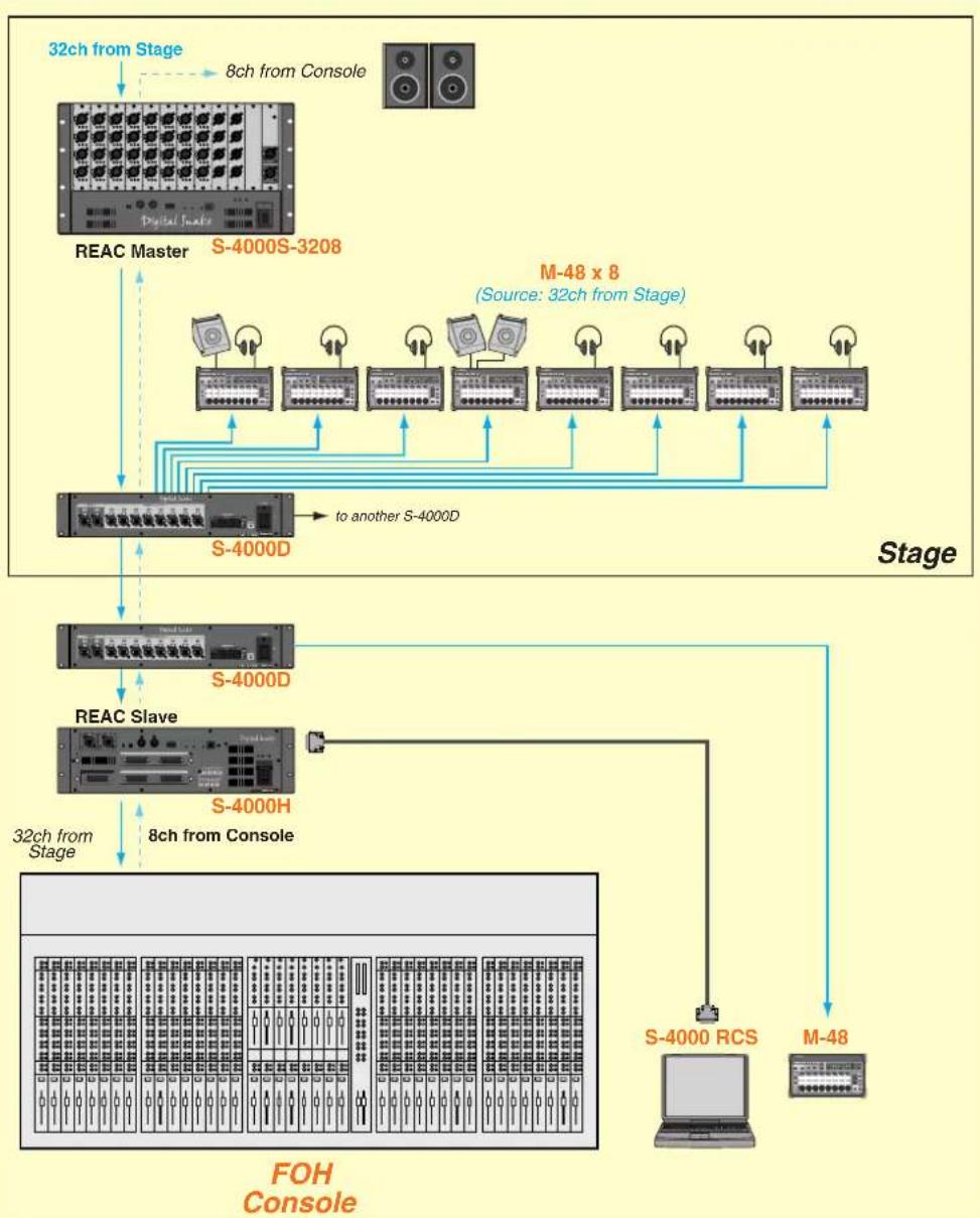
flowchart
graph TD
    A["FOH Console"] -->|32ch from Stage| B["REAC Master"]
    B --> C["S-4000S-3208"]
    C --> D["M-48 x 8 (Source: 32ch from Stage)"]
    D --> E["S-4000D"]
    E --> F["to another S-4000D"]
    F --> G["S-4000D"]
    G --> H["REAC Slave"]
    H --> I["S-4000H"]
    I --> J["32ch from Stage"]
    J --> K["S-4000 RCS"]
    K --> L["M-48"]
    L --> M["FOH Console"]
    style A fill:#f9f,stroke:#333
    style B fill:#ccf,stroke:#333
    style C fill:#cfc,stroke:#333
    style D fill:#fcc,stroke:#333
    style E fill:#cff,stroke:#333
    style F fill:#ffc,stroke:#333
    style G fill:#fcf,stroke:#333
    style H fill:#cff,stroke:#333
    style I fill:#ffc,stroke:#333
    style J fill:#cfc,stroke:#333
    style K fill:#fcc,stroke:#333
    style L fill:#ffc,stroke:#333
    style M fill:#fcc,stroke:#333
In this example, an M-48 unit is also placed by the engineer. By copying settings from another M-48 unit, the engineer can monitor the mix of a musician.
S-4000 RCS allows you to use the M-48 Manager to edit and manage M-48 units that are connected to the system. The mixing engineer can edit and manage the settings of each M-48 unit, allowing each musician to use their M-48 unit more conveniently.
The mixing engineer can make the following settings.
| Setting | See page Edit window | |
| Editing the channel settings of the Digital Snake system | p. 13 | S-4000 RCS window |
| Editing the unit name | p. 43 | M-48 Manager window |
| Editing the preference settings | p. 54 | M-48 Preferences window |
| Setting the source's LEVEL, PAN, and AUX switch (Source level/pan settings) | p. 50 | M-48 Source Lev/Pan window |
| Assigning sources to groups (Source assign settings) | p. 52 | M-48 Source Assign window |
You can also use the following functionality for editing and managing M-48 units.
| Setting | See page Edit window | |
| View a list of connected M-48 units | p. 42 | M-48 Manager window |
| Viewing and editing a musician's mix (Group mix) | p. 56 | |
| Muting the output of a unit | p. 43 | |
| Disabling memory operations from M-48 Manager (MEMORY SAFE function) | p. 43 | |
| Copying/pasting all parameters between units | p. 44 | |
| Unit memory operations | p. 45p. 58 | |
| Saving or loading the data of a unit (Saving or loading an M-48 project le) | p. 45p. 62 | |
| Using the M-48 library | p. 60 | M-48 Library window |
| Associating scene recall with M-48 memory recall | p. 21 | S-4000 RCS window |
Where settings are stored
Settings for each M-48 unit are stored within the respective M-48 unit. M-48 Manager can load the settings from each connected M-48 and edit them.
M-48 settings can be stored externally in either of the following two ways.
- Store the current settings to the M-48 library
- Save all M-48 data as an M-48 project file

M-48 library data is stored within the S-4000 RCS project.
The M-48 Manager window
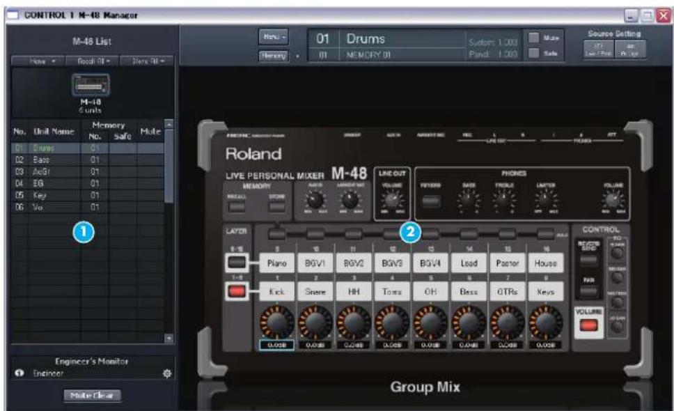
| Item | Name Function | |
| 1 | M-48 List | Here you can select one of the M-48 units connected to the system (p. 42). |
| 2 | Unit editing panel | Here you can edit the settings of the unit selected in the M-48 List (p. 48). |
Opening the M-48 Manager window
- Press the [M-48] button of a controller to which an M-48 unit is connected.
The M-48 Manager window will open.
* The settings for each unit and the M-48 library data will remain even after you close the M-48 Manager window.
Operating from two computers
If S-4000RCS is connected to both the REAC master device and a REAC slave device of the Digital Snake system, settings can be edited only from the computer that opened the M-48 Manager window first. If you open the M-48 Manager window on the other computer, the title bar will indicate “(View Only),” and editing will not be possible.
If you want to clear the “(View Only)” indication and enable editing, proceed as follows.
- Close the M-48 Manager window on both computers.
- Open the M-48 Manager window on the computer that you want to use for editing.
MEMO
The M-48 Manager window can be opened individually for each controller.
MEMO
To close the window, click the close button in the title bar.
Operations in the M-48 List
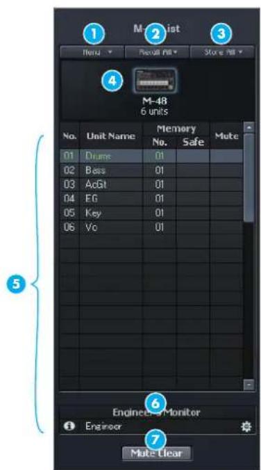
| Item | Name Function | ||
| 1 | [Menu] button | This is the M-48 List menu. | |
| 2 | [Recall All] button Recalls the memories of all units in the M-48 List. | ||
| 3 | [Store All] button Stores the memories of all units in the M-48 List. | ||
| 4 | Number of units Indicates the number of units in the M-48 List. | ||
| 5 | List | No. Indicates the number within the M-48 List. | |
| Unit Name | Indicates the name of the unit. Double-click this to edit the unit name. | ||
| Memory No. Indicates the current memory number. | |||
| Memory Safe | If you click this to add a check mark, memory operations from M-48 Manager will be prohibited. | ||
| Mute | If you click this to add a check mark, the unit's output will be muted. | ||
| 6 | Engineer's Monitor area | This shows the unit designated as the Engineer's Monitor (p. 46). | |
| 7 | [Mute Clear] button | Clears muting for all units in the M-48 List. This will blink red if any units are muted. | |
Menu
| Menu item | Function |
| Copy | Copies all current parameters of the unit selected in the M-48 List to the clipboard. |
| Paste | Pastes the copied parameters from the clipboard to the unit selected in the M-48 List. |
| Paste Special... | Pastes the copied parameters from the clipboard to the unit selected in the M-48 List (you can select the content to be pasted). |
| Save Selected... Saves all data from the unit selected in the M-48 List as an M-48 project file. | |
| Update AllM-48...* | Updates the system program of all units in the M-48 List. |
* For details on updating the M-48 system program, refer to the documentation provided with the updater.
MEMO
The unit currently shown in the M-48 edit panel (p. 48) is shown in green.
MEMO
Paste, Paste Special..., and Save Selected... can be executed on multiple units selected in the M-48 List.
Operations in the M-48 List
Selecting a unit
- Click the desired unit.
Editing the unit name
- Double-click the Unit Name eld of the desired unit. The unit name will become editable.
Changing the order of units in the list
- Drag and drop a unit name to the desired location in the list.
The order of the units displayed in the M-48 List will change.
* A blue line indicating the destination is shown while you drag the unit name.
Muting the output of a unit
Here's how to mute all outputs of a unit.
- Click the Mute eld of the desired unit to make a check mark appear. Muting will be turned off if you click the Mute field once again to clear the check mark.
* You can also mute the selected unit by using the [Mute] button in the M-48 edit panel (p. 48).
Disabling memory operations from M-48 Manager (MEMORY SAFE function)
Units for which the MEMORY SAFE function is turned on will no longer respond to memory operations from M-48 Manager.
- Click the Memory Safe eld of the desired unit to make a check mark appear.
MEMORY SAFE will be turned off if you click the Memory Safe field once again to clear the check mark.
* You can also turn the MEMORY SAFE function on/off for the selected unit by using the [Safe] button in the M-48 edit panel (p. 48).
It is convenient to use the MEMORY SAFE function for purposes such as the following.
- Preventing inadvertent memory operations when managing a large number of units
- Excluding a specific unit when associating scene memories and M-48 memories (p. 21)
- Excluding a specific unit from the M-48 List "Store All" operation (p. 45) or "Recall All]" operation (p. 45)

You can select multiple units by clicking while you hold down [Shift] or [Ctrl].

You can enter a unit name consisting of up to eight single-byte alphanumeric characters.

The displayed order in the M-48 List is saved in the S-4000 RCS project.

You can use the [Mute Clear] button to clear muting for all units in the M-48 List in a single step.
Menu operations
Copying/pasting all parameters between units
1. Select the copy-source unit, and click Menu > Copy.
All current parameters of the copy-source unit will be copied to the clipboard.
* If multiple units are selected in the M-48 List, the parameters will be copied from the unit you clicked last.
2. Select the paste-destination unit, and click Menu > Paste.
The parameters copied to the clipboard in step 1 will be pasted to the paste-destination unit.
* You can select multiple units in the M-48 List as the paste-destination.
* The time required for the paste operation will depend on the number of units you selected.
Copying/pasting specific parameters between units
1. Select the copy-source unit, and click Menu > Copy.
All current parameters of the copy-source unit will be copied to the clipboard.
* If multiple units are selected in the M-48 List, the parameters will be copied from the unit you clicked last.
2. Select the paste-destination unit, and click Menu > Paste Special...
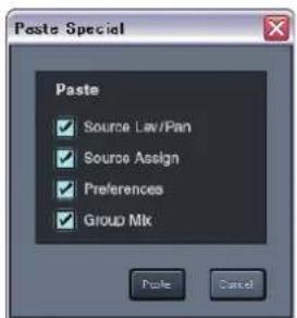
The Paste Special dialog box will appear.
* You can select multiple units in the M-48 List as the paste-destination.
* The time required for the paste operation will depend on the number of units you selected.
3. Add a check mark to the parameters that you want to paste.
| Selection | Explanation |
| Source Lev/Pan | Paste the source level / pan settings. |
| Source Assign Paste the source | assign settings. |
| Preferences Paste the preference | settings. |
| Group Mix Paste the group | mix. |
4. Click the [Paste] button.
Of the parameters copied to the clip board in step 1, the parameters you selected in step 3 will be pasted to the paste-destination unit(s).
MEMO
The unit name will be appended to the command; e.g., Copy "Drums."
?
The clipboard is a memory area provided within S-4000 RCS. You can copy the parameters of a unit to the clipboard, and paste the contents of the clipboard to another unit.
MEMO
The unit name will be appended to the command; e.g., Copy "Drums."
?
The clipboard is a memory area provided within S-4000 RCS. You can copy the parameters of a unit to the clipboard, and paste the contents of the clipboard to another unit.
Saving all data of one or more units (Saving multiple units in a single operation)
- Select the desired unit(s), and click Menu > Save Selected...

The Save Selected dialog box will appear.
-
Click the [Browse...] button and specify the save-destination folder.
-
Click the [OK] button.
A message box will ask you to confirm the operation.
- Click the [OK] button.
A message box indicating the progress of the save operation will appear. When the "Completed" indication appears, saving is complete.
* All data of the unit(s) selected in step 1 will be saved as individual M-48 project files.
* Each M-48 project file will be automatically given a name composed like this: "the number in the list" + "unit name" + file name extension (.m48pj).
* If an M-48 project file of the same file name exists in the location you specified in step 2, the old file will be overwritten by the new file.
MEMO
You can select multiple units in the M-48 List.
MEMO
It takes approximately 30 seconds to save the data of one unit. The length of time required for saving will depend on the number of units you selected in step 1.
Memory operations
Storing the memories of all units
This operation stores the current memories of all units in the M-48 List to the memory you specify (except for units whose MEMORY SAFE function is on).
- From the [Store All] button, select the desired memory number.
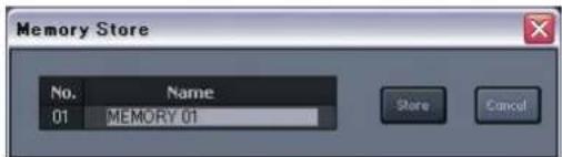
The Memory Store dialog box will appear.
- In the Name box, edit the memory name.
- Click the [Store] button.
Recalling the memories of all units
This operation recalls the memory you select to the current memories of all units in the M-48 list (except for units whose MEMORY SAFE function is on).
- From the [Recall All] button, select the desired memory number.
MEMO
You can enter up to sixteen single-byte alphanumeric characters as the memory name.
Using the Engineer's Monitor function
By designating an M-48 located beside the engineer as the Engineer's Monitor, he/she can monitor and control the mix of any musician's M-48 unit from the Engineer's Monitor.
Specifying an Engineer's Monitor unit
- Select a target unit on the M-48 List and drag it to the Engineer's Monitor area (6. 42).
A message box will ask you to confirm the operation.
- Click the [OK] button.

The specified unit will be displayed on the Engineer's Monitor area.
- To monitor a musician's mix, select the corresponding M-48 unit in the M-48 List.
- You can also control the musician's group mix from the Engineer's Monitor.
* To control the musician's mix from the Engineer's Monitor, the Monitor-only check box on the Engineer's Monitor Option (p. 47) must be cleared.
The following knobs work independently on the engineer's side and musician's side. The positions of each knob on the musician's side are displayed on the M-48 Manager window:
• [AUX IN] knob
• [AMBIENT MIC] knob
• LINE OUT [VOLUME] knob
• [BASS] knob
• [TREBLE] knob
• [LIMITER] knob
• PHONES [VOLUME] knob

Viewing version info for the Engineer's Monitor
- Click the [info] button on the Engineer's Monitor area.
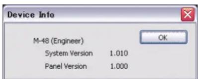
The Device Info window shows the system program version and the panel program version of the unit specified as the Engineer's Monitor.
MEMO
On the Engineer's Monitor, you cannot monitor the AUX IN or the AMBIENT MIC on the musician's side.
MEMO
You cannot use Engineer's Monitor function if system program version of the M-48 is prior to 1.01.
MEMO
The solo function on the M-48 works independently on the musician's side and engineer's side. Therefore, solo operation on the engineer's side does not affect the musician's side.
Editing the Engineer's Monitor preference settings
- Click the [pref] button on the Engineer's Monitor area.
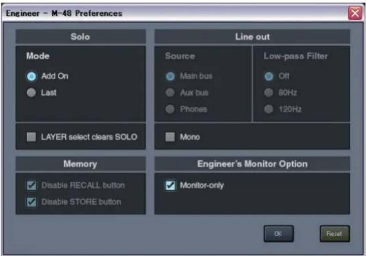
The M-48 Preferences window will be opened. You can set the following items:
- Solo Mode
- LAYER select clears SOLO
- Line Out Mono
• Engineer's Monitor Option
By checking the Monitor-only check box on the Engineer's Monitor option, the Engineer's Monitor unit works only for audio monitoring, and it does not control the musician's mix.
Releasing the Engineer's Monitor
-
Drag the unit name shown in the Engineer's Monitor area to the M-48 List.
A message box will ask you to confirm the operation. -
Click the [OK] button.
The Engineer's Monitor will be released.
Note to use the Engineer's Monitor function
* The Engineer's Monitor function is driven by the M-48 Manager window. Therefore, it will be disabled when you close the M-48 window.
MEMO
The Line out Source setting and the Low-pass Filter setting follows the setting of the musician's unit.
MEMO
MEMORY operation on the Engineer's Monitor is not allowed.
Operations in the M-48 edit panel
M-48 edit panel
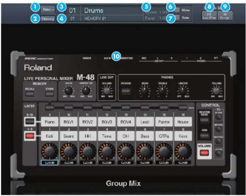
| Item | Name Function | |
| 1 | [Menu] button | This is the menu for the M-48 edit panel. |
| 2 | [Memory] button Opens the M-48 Memory window (p. 58). | |
| 3 | Unit name Indicates the number and name of the selected unit. | |
| 4 | Memory Indicates the number and name of the current memory. | |
| 5 | Version | Indicates the version of the unit.System : Indicates the system program version.Panel : Indicates the panel program version. |
| 6 | [Mute] button | Turns muting on/off. Lit red when on. |
| 7 | [Safe] button Turns the MEMORY SAFE function on/off. Lit green when on. | |
| 8 | [Lev/Pan] button Opens the M-48 Source Lev/Pan window (p. 50). | |
| 9 | [Assign] button Opens the M-48 Source Assign window (p. 52) | |
| 10 | Group Mix Adjusts the group mix (p. 56). | |
Menu
| Menu item | Function |
| Copy | Copies the unit's settings. |
| Paste Pastes the copied settings. | |
| Paste Special... | Pastes the copied settings (and allows you to select the content that will be pasted). |
| Reset Group Mix Resets the group mix (p. 57). | |
| Library... Accesses the M-48 Library window (p. 60). | |
| Save... Saves all data of the unit as an M-48 project file (p. 62). | |
| Load... Loads an M-48 project file into the unit (p. 62). | |
| Blink LEDs Causes all of the unit's LEDs to blink. Use this to identify the selected unit. | |
| Preferences... Accesses the M-48 Preferences window (p. 54). | |
MEMO
The procedure for using Copy, Paste, and Paste Special is the same as for the M-48 List (p. 42). However, the copy destination is limited to the currently selected unit.
Operations using the keyboard
| Key | Operation |
| [←] ↗ [ | $ selects a [Control] knob |
| [↑] ↘ [ | Increase or decrease the value of the [Control] knob |
| [enter] Edits the group name | |
| [V] Opens the M-48 Source Lev/Pan window (p. 50). | |
| [A] Opens the M-48 Source Assign window (p. 52) | |
| [M] Opens the M-48 Memory window (p. 58). | |
| [ctrl] + [B] Turn on/off the Blink LEDs function (p. 49). | |
Editing the group name
1. Double-click the group name in the Group Mix area.
The group name will become editable.
Blinking the unit's LEDs
1. Click Menu > Blink LEDs to add a check mark.
All LEDs of the unit will blink. The [Clear Blink] button will appear in the lower right of the M-48 edit panel.
2. To stop the LEDs from blinking, click the [Clear Blink] button.
* The LED blinking will also be cleared when a button on the M-48 itself is operated.
* You can also clear the LED blinking by clicking Menu > Blink LEDs to clear the check mark.
Editing when the serial port is not connected (Editing a virtual unit)
If no serial port is selected in the serial port selection box (p. 13) of the S-4000 RCS window, the M-48 edit panel will show a unit named "Virtual."

The following operations cannot be performed for a "Virtual" unit.
- Edit the unit name "Virtual"
• Store or recall M-48 memories - Use the MEMORY SAFE function or make output mute settings
- Save or load M-48 project files
When you select a serial port in the serial port selection box of the S-4000 RCS window, the "Virtual" unit will no longer be displayed. If you store the settings of the "Virtual" unit to the M-48 library (p. 60) before you select a serial port, you will be able to recall (p. 61) those settings for a real unit.

You can enter up to six single-byte alphanumeric characters as the group name.

This is a convenient way to verify which unit is selected.
Setting the source's LEVEL, PAN, and AUX switch (Source level/pan settings)
M-48 Source Lev/Pan window
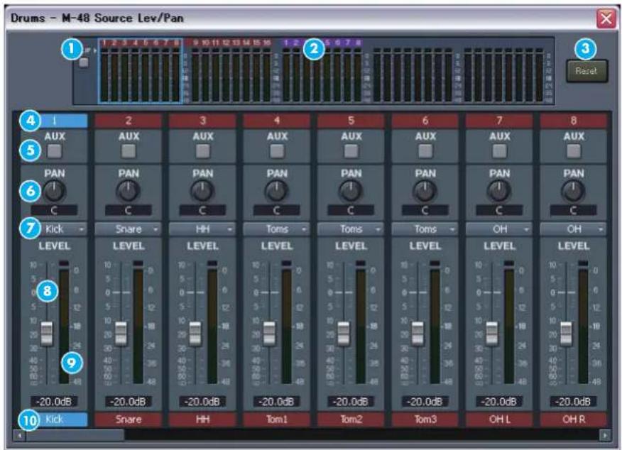
| Item | Name Function | |
| 1 | [CLIP] button | Click this to clear the clip indicators and peak hold indicators. This button will light red if a level meter clip indicator is lit. |
| 2 | Level meters Indicate | the pre-fader levels of the sources. |
| 3 | [Reset] button Resets | the source level/pan settings. |
| 4 | Source number | Indicates the Digital Snake's channel number, corresponding to sources 1–40.Brown background : Indicates an input of the REAC master device.Purple background : Indicates an input of a REAC slave device. |
| 5 | AUX switch | Turns the send to the AUX bus on/off. Lit orange when on. |
| 6 | PAN knob Sets the panning of the source. | |
| 7 | Group select box Selects the group to which the source is assigned. | |
| 8 | Fader Adjusts the level of the source. | |
| 9 | Source level meter Indicates the pre-fader level of the source. | |
| 10 | Source name Indicates the name of the channel within the Digital Snake system. |
Opening the M-48 Source Lev/Pan window
- In the M-48 edit panel, click the [Lev/Pan] button.
The M-48 Source Lev/Pan window will open.

To close the window, click the close button in the title bar.
Editing the source level / pan settings
- Open the M-48 Source Lev/Pan window.
- Click the AUX switch to turn it on/off.
If you turn on the AUX switch, the post-fader, post-pan signal will be sent to the AUX bus.
- Adjust the PAN setting.
You can adjust this in a range of L63-C-R63.
* To reset the knob to C (center), hold down [Ctrl] and click the PAN knob.
4. Adjust the LEVEL.
You can adjust this in a range of -Inf dB- +10.0 dB.
* To reset the LEVEL to 0.0 dB, hold down [Ctrl] and click the fader.
- Use the group select box to assign the source to a group.
| Selection | Function |
| (Not Assign) or (MAIN) | The source is not assigned to any group. The display differs depending on the Mix Option (p. 52) setup. |
| 1–16 The source is assigned to the group of the selected number. | |
Operations using the keyboard
| Key | Operation |
| [←] ↗ [ | Selects a source |
| [shift] + [ ]/ [ ] → | Selects a source (in 8-channel steps) |
| [↑] ↘ [ | Raises or lowers the LEVEL |
Resetting the source level / pan settings
- Open the M-48 Source Lev/Pan window.
- Click the [Reset] button.
A message box will ask you to confirm the operation.
- Click the [OK] button.
The parameters of each source will be reset to the following values.
| Parameter | value |
| AUX switch | ON |
| PAN C | |
| LEVEL -Inf dB |

For an example of source level / pan settings, refer to "Example setups" (p. 63)

To output the AUX bus signal, use the preference settings (p. 54) to select "Aux bus" as the line out source.

If you select "Not Assign" in the group select box, this source will not be operable from the panel of the M-48 itself. If you don't want this source to be output, you'll need to turn down the LEVEL to -Inf dB.

Assignments of sources to groups can also be made using the source assign settings (p. 52).

This operation will not reset the group selections. Use M-48 Source Assign window (p. 52) to reset the group selections.
Assigning sources to groups (Source assign settings)
M-48 Source Assign window
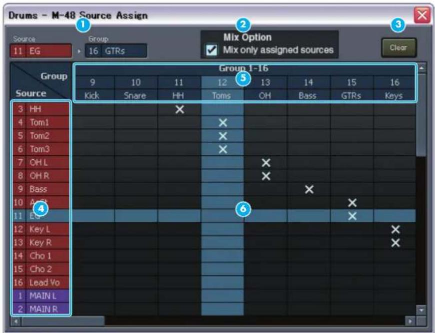
| Item | Name Function | |
| 1 | Current assignment | Indicates the group to which the source at the cursor location is currently assigned. |
| 2 | Mix Option | This sets the M-48's mix option. By checking the “Mix only assigned sources” check box, only sources assigned to a group will be mixed. |
| 3 | [Clear] button Clears | the source assign settings. |
| 4 | Source list | Shows the Digital Snake channel numbers and channel names corresponding to sources 1–40.Brown background : Indicates an input of the REAC master device.Purple background : Indicates an input of a REAC slave device. |
| 5 | Group list | Shows the number and name of each group. |
| 6 | Assignment grid | An icon is shown at the intersection of a currently assigned source and group. |
Opening the M-48 Source Assign window
- In the M-48 edit panel, click the [Assign] button.
The M-48 Source Assign window will open.
MEMO
You cannot check the "Mix only assigned sources" check box if system program version of the M-48 is prior to 1.01.
MEMO
To close the window, click the close button in the title bar.
Making source assignments
- Open the M-48 Source Assign window.
- Click the location where the desired source and group intersect.
An icon will appear.
* To cancel an assignment, click the corresponding assignment symbol.
* A source can be assigned only to one group. You cannot assign a source to multiple groups.
Operations using the keyboard
| Key | Operation |
| [←] ↗ [ | Selects a group |
| [shift] + [↑/ [ ] → | Selects a group (in 8-group steps) |
| [↑] ↘ [ | Selects a source |
| [shift] + [↑/ [ ] ↓ | Selects a source (in 10-channel steps) |
If the "Mix only assigned sources" on the Mix Option ② not checked, a source that is not assigned to any group will also be mixed to the M-48's MAIN buses, and that source cannot be controlled from the M-48's panel.
In some cases you may want to include a source without being able to control it from the M-48's panel:
1. For talkback communication
The mixing engineer can have talkback as one of the sources, leaving the source level up but not assigned to a particular group (knob). This way the talkback signal is not controlled by any of the M-48 knobs yet still can be heard by the musician.
2. To provide simple control
E.g., The mixing engineer can provide just vocal control for a vocalist via source assignment. All other sources are not assigned to any groups (knobs) and can be provided as a fixed mix. The vocalist just adjusts the volume of their voice alone.
Clearing the source assign settings
- Open the M-48 Source Assign window
- Click the [Clear] button.
A message box will ask you to confirm the operation.
- Click the [OK] button.
The group assignments of all sources will be cleared.

For an example of source assign settings, refer to
"Example setups" (p. 63)
Editing the preference settings
M-48 Preferences window
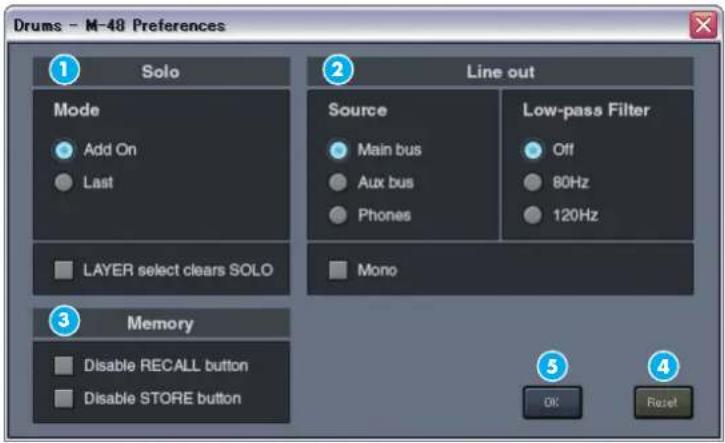
| Item | Name Function | ||
| 1 | Solo | Mode Selects the solo mode. | |
| LAYER select clears SOLO | When the layer is switched on the M-48 itself, the solo settings of the now-hidden layer will be cleared automatically. | ||
| 2 | Line Out | Source SourceSelects the source for the line out. | |
| Low-pass Filter Specifies the low-pass filter setting for the line out. | |||
| Mono Turns the mono switch on/off. | |||
| 3 | Memory | Disable RECALL button | Disables the M-48's [RECALL] button. |
| Disable STORE button | Disables the M-48's [STORE] button. | ||
| 4 | [Reset] button Resets the preference settings. | ||
| 5 | [OK] button Closes the M-48 Preferences window. | ||
Opening the M-48 Preferences window
- In the M-48 edit panel, click Menu > Preferences...
The M-48 Preferences window will open.
Editing the preference settings
-
Open the M-48 Preferences window.
-
Specify the Solo setting.
- Mode
Select the solo mode.
| Selection | Explanation |
| Add On | Solo can be turned on for multiple groups. The soloed groups will be mixed for monitoring. |
| Last | Only the group whose solo setting was last turned on will be monitored. |

To close the window, click the [OK] button.
- LAYER select clears SOLO
If this is checked, the solo settings of the now-hidden layer will be cleared automatically when the layer is switched.
3. Make settings for Line Out.
- Source
Select the source for line out.
| Selection | Explanation |
| Main bus | Output the Main bus signal. |
| Aux bus | Output the Aux bus signal (the mixed sources whose AUX switch is turned on in the source level/pan settings). |
| Phones Output the | signal going to the PHONES. This includes ambient mic. |
- Low-pass Filter
Select the low-pass filter setting for the line out.
| Selection | Explanation |
| Off | The low-pass filter will not be used. |
| 80Hz The frequency range below 80 Hz will be passed. | |
| 120Hz The frequency range below 120 Hz will be passed. | |
* When switching the low-pass filter setting from 80Hz/120Hz to Off, take care that excessive strain is not applied to your hearing or to the equipment connected to line out.
- Mono
If this is checked, a monaural mix will be output from line out.
4. Make Memory settings.
- Disable RECALL button
If this is checked, the M-48's [RECALL] button will be disabled.
- Disable STORE button
If this is checked, the M-48's [STORE] button will be disabled.
Resetting the preference settings
-
Open the M-48 Preferences window.
-
Click the [Reset] button.
A message box will ask you to confirm the operation.
- Click the [OK] button.
The preference settings will be reset to the following values.
| Parameter | value | |
| Solo | Mode Add On | |
| LAYER select clears SOLO No | ||
| Line Out | Source No | |
| Low-pass Filter No | ||
| Mono Main bus | ||
| Memory | Disable RECALL button Off | |
| Disable STORE button Off | ||

The low-pass filter is a 12 dB/ octave filter that passes only the frequency range lower than the specified frequency.
Viewing and editing a musician's mix (Group mix)
The M-48 edit panel's Group Mix area is used to view and edit the group mix.
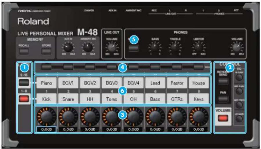
Viewing and editing the group mix
- Click a button in the layer selection section to select a layer.
- Click a button in the control selection section ② select the parameter that will be shown for the [Control] knobs ③
- Use the [Control] knobs edit the parameters of the group.
* By clicking a [Control] knob while holding down [Ctrl], parameters can be reset individually. For the reset value, refer to the table in "Resetting the group mix" (p. 57).
- Use the [SOLO] buttons ④ turn solo on/off for each group.
If solo is on, the [Solo Clear] button will be shown.
By clicking this you can clear solo for all groups.
- Use the [REVERB] button turn reverb on/off.
* The following buttons and knobs cannot be operated from Group Mix.
- [RECALL] button
- [STORE] button
• [AUX IN] knob
• [AMBIENT MIC] knob
• LINE OUT [VOLUME] knob
• [BASS] knob
• [TREBLE] knob
• [LIMITER] knob
• PHONES[VOLUME] knob

The procedure for Group Mix operations is the same as when operating the panel of the M-48 itself. For details, refer to "M-48 Owner's Manual."
MEMO
The VOLUME adjustment is relative to the LEVEL specified in the source level/pan settings. In some cases, the source's LEVEL may reach the maximum or minimum value before the VOLUME reaches its maximum or minimum value.
MEMO
The PAN adjustment is relative to the PAN specified in the source level/pan adjustment. In some cases, the source's PAN may reach the maximum or minimum value before this PAN adjustment reaches its maximum or minimum value.
Operations using the keyboard
| Key | Operation |
| [←] ↗ [ ] | Selects a [Control] knob |
| [↑] ↘ [ ] | Increases or decrease the value of the [Control] knob |
| [enter] Edits the group name | |
Editing a group name
1. Double-click the group name 📊 Group Mix.
The group name will be editable.
Resetting the group mix
1. In the M-48 edit panel, click Menu > Reset Group Mix.
A message box will ask you to confirm the operation.
2. Click the [OK] button.
The parameters of each group will be reset to the following values.
| Parameter | value |
| VOLUME | 0.0 dB |
| PAN C | |
| REVERB SEND -Inf dB | |
| HI GAIN 0.0 dB | |
| MID GAIN 0.0 dB | |
| MID FREQ 1.00 kHz | |
| LO GAIN 0.0 dB | |
| SOLO Off | |
![ROLAND M-48 - Click the [OK] button. - 1](/content/2026/05/940548/images/13fa88515a7ac5bb212794daad3f170a13c1e0da8583def25fdb78635a61dbc6.jpg)
You can enter up to six single-byte alphanumeric characters as the group name.
Unit memory operations
M-48 Memory window
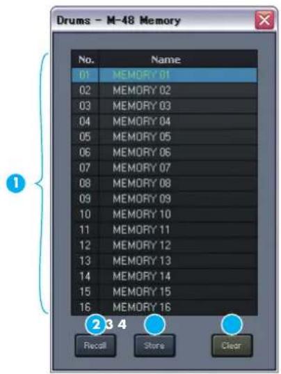
| Item | Name Function | ||
| 1 | Memory list | No. Indicates the memory number. | |
| Name | Indicates the memory name. Double-click this to edit the memory name. | ||
| 2 | [Recall] button Recalls settings from the selected memory number. | ||
| 3 | [Store] button Stores settings to the selected memory number. | ||
| 4 | [Clear] button Clears the contents of the selected memory. | ||
Opening the M-48 Memory window
- In the unit editing pane, press the [Memory] button.
The M-48 Memory window will open.
Storing a memory
- Open the M-48 Memory window.
- In the memory list, select the store-destination memory.
- Click the [Store] button.
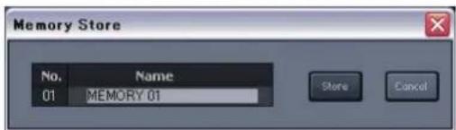
The Memory Store dialog box will open.
-
In the Name box, edit the memory name.
-
Click the [Store] button.
The current memory of the unit will be stored to the memory you selected in step 1.
MEMO
The current memory is shown in green.
MEMO
To close the window, click the close button in the title bar.
MEMO
You can also use the [S] key on the keyboard to open the Memory Store dialog box.
MEMO
You can enter up to sixteen single-byte alphanumeric characters as the memory name.
Recalling a memory
- Open the M-48 Memory window.
- In the memory list, select the desired memory.
- Click the [Recall] button.
The memory you selected in step 2 will be recalled to the current memory of the unit.
Editing the memory name
- Open the M-48 Memory window.
- In the memory list, double-click the Name eld of the desired memory. The memory name will be editable.
Clearing the contents of a memory
- Open the M-48 Memory window.
- In the memory list, select the desired memory.
-
Click the [Clear] button.
A message box will ask you to confirm the operation. -
Click the [OK] button.
The contents of the memory you selected in step 3 will be cleared to the default state.

You can enter up to sixteen single-byte alphanumeric characters as the memory name.

You can also clear the contents of the selected memory by pressing the [Delete] key of your computer.
Using the M-48 library
The current settings of the unit can be saved as M-48 library data. The M-48 library data is saved within the S-4000 RCS project.
M-48 Library window
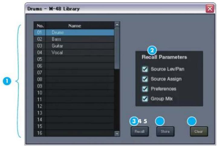
| Item | Name Function | ||
| 1 | Library list | No. Indicates the library number. | |
| Name | Indicates the library name. Double-click this to edit the library name. | ||
| 2 | [Recall] button Recalls settings from the selected library number. | ||
| 3 | [Store] button Stores settings to the selected library number. | ||
| 4 | [Clear] button Clears the selected library. | ||
Opening the M-48 Library window
- In the M-48 edit panel, click Menu > Library...
The M-48 Library window will open.
Storing to the library
- Open the M-48 Library window.
- In the library list, select the store-destination library number.
- Click the [Store] button.
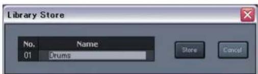
The Library Store dialog box will appear.
-
In the Name box, edit the name.
-
Click the [Store] button.
The unit's current settings will be stored to the library number you selected in step 2.

To close the window, click the close button in the title bar.

You can enter a name consisting of up to sixteen single-byte alphanumeric characters as the name of a library item.
Recalling from the library
- Open the M-48 Library window.
- In the library list, select the library item that you want to recall.
- In the Recall Parameters selection boxes, add a check mark to the parameters that you want to recall.
| Selection | Explanation |
| Source Lev/Pan Source level / pan settings will be recalled. | |
| Source Assign source assign settings will be recalled. | |
| Preferences Preference settings will be recalled. | |
| Group Mix Group mix settings will be recalled. | |
4. Click the [Recall] button.
The settings of the library item you selected in step 2 will be recalled to the current settings of the unit.
Editing the name of a library item
- Open the M-48 Library window.
- In the library list, double-click the Name eld of the desired library item.
The name of the library item will become editable.
Clearing a library item
- Open the M-48 Library window.
- In the library list, select the desired library item.
- Click the [Clear] button.
A message box will ask you to confirm the operation. - Click the [OK] button.
The data will be cleared from the library item you selected in step 1.
MEMO
You can enter a name consisting of up to sixteen single-byte alphanumeric characters as the name of a library item.
MEMO
You can also clear the selected library item by pressing the [Delete] key of your computer.
Saving or loading the data of a unit (Saving or loading an M-48 project file)
Saving an M-48 project file
- In the M-48 edit panel, click Menu > Save...
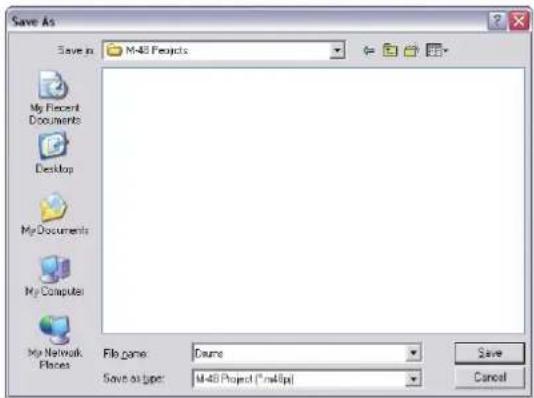
The "Save As" dialog box will open.
-
Specify a folder and le name for saving the M-48 project le.
-
Click the [Save] button.
A message box will ask you to confirm the operation.
- Click the [OK] button.
A message box will indicate the status of saving. When saving is finished, the indication "Completed" will appear.
Loading an M-48 project file
- In the M-48 edit panel, click Menu > Load...
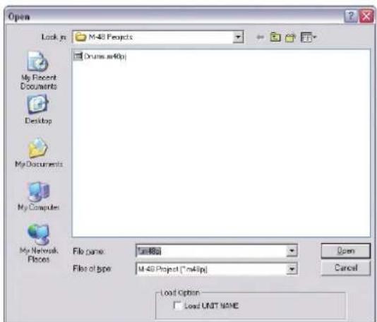
The "Open" dialog box will appear.
-
Select the desired M-48 project le.
-
Click the [Open] button.
A message box will ask you to confirm the operation.
- Click the [OK] button.
A message box will indicate the status of loading. When loading is finished, the indication "Completed" will appear.

It takes approximately 30 seconds to save the data for one unit.

If the Load Option "Load UNIT NAME" box is checked, the unit name will also be loaded.

It takes approximately 30 seconds to load the data for one unit.
Example setup for Drummer
Source level/pan settings Source assign settings
| Source | Level | Pan | |
| 1 | Kick | —0— | ➊ |
| 2 | Snare | —0— | ➊ |
| 3 | Hi Hat | —0— | ➊ |
| 4 | Tom1 | —0— | ➊ |
| 5 | Tom2 | —0— | ➊ |
| 6 | Tom3 | —0— | ➊ |
| 7 | Ride | —0— | ➌ |
| 8 | Crash | —0— | ➌ |
| 9 | Overhead L | —0— | ➌ |
| 10 | Overhead R | —0— | ➌ |
| 11 | Bass | —0— | ➊ |
| 12 | Click | —0— | ➊ |
| 13 | E.Guitar1 L | —0— | ➌ |
| 14 | E.Guitar1 R | —0— | ➌ |
| 15 | E.Guitar2 L | —0— | ➌ |
| 16 | E.Guitar2 R | —0— | ➌ |
| 17 | A.Guitar L | —0— | ➌ |
| 18 | A.Guitar R | —0— | ➌ |
| 19 | Keys L | —0— | ➌ |
| 20 | Keys R | —0— | ➌ |
| 21 | Piano L | —0— | ➌ |
| 22 | Piano R | —0— | ➌ |
| 23 | Lead Vocal | —0— | ➊ |
| 24 | Back Vocal1 | —0— | ➊ |
| 25 | Back Vocal2 | —0— | ➊ |
| 26 | Back Vocal3 | —0— | ➊ |
| 27 | Choir1 | —0— | ➌ |
| 28 | Choir2 | —0— | ➊ |
| 29 | Choir3 | —0— | ➌ |
| 30 | Ambient Mic1 | —0— | ➌ |
| 31 | Ambient Mic2 | —0— | ➌ |
| 32 | Talkback | —0— | ➊ |
| 33 | Main Output L | —0— | ➌ |
| 34 | Main Output R | —0— | ➌ |
| 35 | |||
| 36 | |||
| 37 | |||
| 38 | |||
| 39 | |||
| 40 | |||
* Level/pan settings shown are approximate.
Example setup for lead vocalist
Source level/pan settings Source assign settings
| Source | Level Pan | ||
| 1 | Kick | —0— | ➊ |
| 2 | Snare | —0— | ➊ |
| 3 | Hi Hat | —0— | ➊ |
| 4 | Tom1 | —0— | ➌ |
| 5 | Tom2 | —0— | ➊ |
| 6 | Tom3 | —0— | ➌ |
| 7 | Ride | —0— | ➌ |
| 8 | Crash | —0— | ➌ |
| 9 | Overhead L | —0— | ➌ |
| 10 | Overhead R | —0— | ➌ |
| 11 | Bass | —0— | ➊ |
| 12 | Click | 0— | ➊ |
| 13 | E.Guitar1 L | —0— | ➌ |
| 14 | E.Guitar1 R | —0— | ➌ |
| 15 | E.Guitar2 L | —0— | ➌ |
| 16 | E.Guitar2 R | —0— | ➌ |
| 17 | A.Guitar L | —0— | ➌ |
| 18 | A.Guitar R | —0— | ➌ |
| 19 | Keys L | —0— | ➌ |
| 20 | Keys R | —0— | ➌ |
| 21 | Piano L | —0— | ➌ |
| 22 | Piano R | —0— | ➌ |
| 23 | Lead Vocal | —0— | ➊ |
| 24 | Back Vocal1 | —0— | ➊ |
| 25 | Back Vocal2 | —0— | ➊ |
| 26 | Back Vocal3 | —0— | ➊ |
| 27 | Choir1 | —0— | ➌ |
| 28 | Choir2 | —0— | ➊ |
| 29 | Choir3 | —0— | ➌ |
| 30 | Ambient Mic1 | —0— | ➌ |
| 31 | Ambient Mic2 | —0— | ➌ |
| 32 | Talk back | —0— | ➊ |
| 33 | Main Output L | —0— | ➌ |
| 34 | Main Output R | —0— | ➌ |
| 35 | |||
| 36 | |||
| 37 | |||
| 38 | |||
| 39 | |||
| 40 | |||
* Level/pan settings shown are approximate.
Example setup for backing vocalists
Source level/pan settings Source assign settings
| Source | Level Pan | ||
| 1 | Kick | —0— | 1 |
| 2 | Snare | —0— | 1 |
| 3 | Hi Hat | —0— | 1 |
| 4 | Tom1 | —0— | — |
| 5 | Tom2 | —0— | 1 |
| 6 | Tom3 | —0— | — |
| 7 | Ride | —0— | — |
| 8 | Crash | —0— | — |
| 9 | Overhead L | —0— | — |
| 10 | Overhead R | —0— | — |
| 11 | Bass | —0— | 1 |
| 12 | Click | 0— | 1 |
| 13 | E.Guitar1 L | —0— | — |
| 14 | E.Guitar1 R | —0— | — |
| 15 | E.Guitar2 L | —0— | — |
| 16 | E.Guitar2 R | —0— | — |
| 17 | A.Guitar L | —0— | — |
| 18 | A.Guitar R | —0— | — |
| 19 | Keys L | —0— | — |
| 20 | Keys R | —0— | — |
| 21 | Piano L | —0— | — |
| 22 | Piano R | —0— | — |
| 23 | Lead Vocal | —0— | 1 |
| 24 | Back Vocal1 | —0— | 1 |
| 25 | Back Vocal2 | —0— | 1 |
| 26 | Back Vocal3 | —0— | 1 |
| 27 | Choir1 | —0— | — |
| 28 | Choir2 | —0— | 1 |
| 29 | Choir3 | —0— | — |
| 30 | Ambient Mic1 | —0— | — |
| 31 | Ambient Mic2 | —0— | — |
| 32 | Talkback *1 | 0— | 1 |
| 33 | Main Output L | —0— | — |
| 34 | Main Output R | —0— | — |
| 35 | |||
| 36 | |||
| 37 | |||
| 38 | |||
| 39 | |||
| 40 | |||
* Level/pan settings shown are approximate.
Appendix
* Please refer the "Troubleshooting" section on page 83 of the S-4000 system owner's manual or page 67 of the S-1608 / S-0816 owner's manual for explanation of any error messages.
| Messages | Problems |
| REAC backup. | REAC communication has switched from the Main to the Backup cable. |
| Master Fan Error. Cooling fan of | of REAC master device has stopped. |
| Slave Fan Error. Cooling fan of | REAC slave device has stopped. |
| Master Temperature Error. | An abnormal temperature increase has been detected in the REAC master device. |
| Slave Temperature Error. | An abnormal temperature increase has been detected in the REAC slave device. |
| Master Slot Error. Modules in | the REAC master device are not configured properly. |
| REAC packet Error. A REAC | protocol transfer error has been detected. |
| All Mute. All outputs from the | system have been muted. |
| Host Link Down. Serial comm | unication via RS-232C is terminated. |
| REAC Link Down. REAC trans | fer is terminated. |
- Introduction 5
- Introduction ......6
- Digital snake system settings 9
- Connections with a Digital Snake system ....10
- Operations in the S-4000 RCS window ....12
- Editing the S-4000M's Input/Output Settings ....22
- Managing the M-48 Live Personal Mixer ...... 31
- What is the M-48 live personal mixer ....32
- Connecting M-48 units to a Digital Snake system ....34
- Editing and managing M-48 units....40
- Operations in the M-48 Manager window ....41
- Operations in the M-48 List....42
- Operations in the M-48 edit panel ....48
- Introduction
- Main features
- Starting and exiting S-4000 RCS
- Starting S-4000 RCS
- Exiting S-4000 RCS
- About S-4000 RCS projects
- Saving an S-4000 RCS project
- Opening an S-4000 RCS project file
- Opening a new S-4000 RCS project le
- Opening an existing S-4000 RCS project le
- Digital snake system settings
- Serial port connections
- Caution for serial connections
- Starting a connection with a Digital Snake system
- In the controller's serial port select box, choose the serial port to which the desired Digital Snake system is connected.
- Caution when starting a connection
- If more than one system is connected
- MEMO
- The S-4000 RCS window
- Editing the channel settings of the Digital Snake system
- Opening a controller
- Opening the controller's channel edit panel
- Locking/unlocking the controller
- Storage of channel settings
- Editing the channel name
- Turning stereo link on/off
- Turning +48V phantom power on/off
- Caution when using +48V phantom power
- Adjusting the preamp gain
- Operations using the keyboard
- Assigning Physical Inputs to Channels (S-4000M)
- Select sources to be displayed (S-MADI)
- Setting the S-MADI's configuration
- Level meter settings
- Viewing version info for the Digital Snake
- Using scene memories
- What are scene memories
- How scene memories are associated with M-48 memories
- Notes regarding scene memories
- Scene memories
- Storing channel settings to a scene
- Recalling channel settings from a scene
- Editing the name of a scene
- Associating scene recall with M-48 memory recall
- Editing the S-4000M's Input/Output Settings
- Merge Patchbay
- Output Patchbay
- Storing Input/Output Setups
- S-4000M Configuration Window
- Opening S-4000M Configuration Window
- Resetting Input/Output Setups (System Reset)
- Merge Patchbay Operations
- MERGE View
- Switching to MERGE View
- S-4000M Merge Patchbay Window
- Opening the S-4000M Merge Patchbay window
- Making assignment in the S-4000M Merge Patchbay
- Clearing All Assignments
- Output Patchbay Operations (S-0808)
- OUTPUT View
- Switching to OUTPUT View
- S-4000M Output Patchbay Window
- Opening the S-4000M Output Patchbay window
- Making assignments in the S-4000M's Output Patchbay window
- Splitting Merged Inputs (S-4000M's Split Function)
- Notes About the S-4000M's Split Function
- Using S-4000M's Split Function
- Save/Load the S-4000M Input/Output Setup
- Saving the S-4000M Input/Output Setup as Computer File
- Loading the S-4000M Input/Output Setup File
- Managing the M-48 Live Personal Mixer
- What is the M-48 live personal mixer
- 40-channel mixer
- Settings and operations for the 40-channel mixer
- Settings by the mixing engineer
- Operations performed by the musician
- Two sets of outputs
- PHONES
- LINE OUT
- Memory functionality
- Connections with an S-1608 system
- Note when connecting M-48 units (S-1608 system)
- Note regarding the ordering of M-48 sources
- Example 1: S-1608 + M-48 (16 sources)
- Example 2: S-1608 + S-0816 + M-48 (24 sources)
- Connections with an S-4000 system
- Note when connecting M-48 units (S-4000 system)
- Example 1: S-4000S-4000 + M-48 (40 sources)
- Example 2: S-4000S-3208 + S-4000H + M-48 (32 sources)
- Where settings are stored
- The M-48 Manager window
- Opening the M-48 Manager window
- Operating from two computers
- Operations in the M-48 List
- Selecting a unit
- Editing the unit name
- Changing the order of units in the list
- Muting the output of a unit
- Disabling memory operations from M-48 Manager (MEMORY SAFE function)
- Menu operations
- Copying/pasting all parameters between units
- Select the copy-source unit, and click Menu > Copy.
- Select the paste-destination unit, and click Menu > Paste.
- Copying/pasting specific parameters between units
- Select the paste-destination unit, and click Menu > Paste Special...
- Add a check mark to the parameters that you want to paste.
- Click the [Paste] button.
- ?
- Saving all data of one or more units (Saving multiple units in a single operation)
- Memory operations
- Storing the memories of all units
- Recalling the memories of all units
- Using the Engineer's Monitor function
- Specifying an Engineer's Monitor unit
- Viewing version info for the Engineer's Monitor
- Editing the Engineer's Monitor preference settings
- Releasing the Engineer's Monitor
- Note to use the Engineer's Monitor function
- Operations in the M-48 edit panel
- M-48 edit panel
- Editing the group name
- Double-click the group name in the Group Mix area.
- Blinking the unit's LEDs
- Click Menu > Blink LEDs to add a check mark.
- To stop the LEDs from blinking, click the [Clear Blink] button.
- Editing when the serial port is not connected (Editing a virtual unit)
- Setting the source's LEVEL, PAN, and AUX switch (Source level/pan settings)
- Opening the M-48 Source Lev/Pan window
- Editing the source level / pan settings
- Resetting the source level / pan settings
- Assigning sources to groups (Source assign settings)
- Opening the M-48 Source Assign window
- Making source assignments
- For talkback communication
- To provide simple control
- Clearing the source assign settings
- Editing the preference settings
- M-48 Preferences window
- Opening the M-48 Preferences window
- Make settings for Line Out.
- Make Memory settings.
- Resetting the preference settings
- Viewing and editing a musician's mix (Group mix)
- Viewing and editing the group mix
- Editing a group name
- Double-click the group name 📊 Group Mix.
- Resetting the group mix
- In the M-48 edit panel, click Menu > Reset Group Mix.
- Click the [OK] button.
- Unit memory operations
- M-48 Memory window
- Opening the M-48 Memory window
- Storing a memory
- Recalling a memory
- Editing the memory name
- Clearing the contents of a memory
- Using the M-48 library
- M-48 Library window
- Opening the M-48 Library window
- Storing to the library
- Recalling from the library
- Click the [Recall] button.
- Editing the name of a library item
- Clearing a library item
- Saving or loading the data of a unit (Saving or loading an M-48 project file)
- Saving an M-48 project file
- Loading an M-48 project file
- Example setup for Drummer
- Example setup for lead vocalist
- Example setup for backing vocalists
- Appendix
Brand : ROLAND
Model : M-48
Category : Uncategorized