AZM4 - Microphone Atlas Sound - Free user manual and instructions
Find the device manual for free AZM4 Atlas Sound in PDF.


| Product Type | Digital Signal Processor (DSP) with Microphone/Line Inputs |
| Model | AZM4 |
| Brand | Atlas Sound (AtlasIED) |
| Inputs | 4 balanced mic/line (Euroblock), 2 RCA stereo summed, plus up to 2 accessory wall plate inputs (A-XLR, A-RCA, or A-BT) |
| Outputs | 4 balanced line outputs (Euroblock) |
| Dimensions (with rack ears) | 19" x 1.75" x 11.78" (483 mm x 45 mm x 299 mm) |
| Weight (unit) | 4.735 lbs (2.148 kg) |
| Power Supply | 100-240 VAC, 50-60 Hz, IEC connector, universal |
| Power Consumption | Max 130 BTU/hr (no accessories: 75 BTU/hr) |
| Frequency Response | ±0.5 dB 20 Hz - 20 kHz |
| Dynamic Range | >108 dB unweighted, >110 dB A-weighted |
| THD+N | <0.01% at 0 dBu input/output, 0 dB gain, 1 kHz |
| Latency | 4.9 ms (Euroblock input to output), up to 6.7 ms with accessory input |
| Input Processing | Gate, De-Esser, Compressor, Auto-Gain, 4-band EQ with presets |
| Output Processing | Priority ducking, crossover, 8-band EQ, Tilter Filter, Ambient Noise Compensation, Limiter, speaker presets |
| Network | RJ45 Ethernet (10/100 Mbps), WiFi 802.11 b/g/n 2.4 GHz, Access Point mode |
| Accessory Ports | 2 RJ45 bus ports for wall plate accessories (up to 8 per port, 16 total per AZM) |
| GPIO | 6 control inputs (contact closure or 1.5-12V trigger), 1 high-priority input, 2 control outputs (GPO) with presets |
| Front Panel Display | 128x128 color TFT, encoder knob, light bar (blue=normal, red=fault) |
| Operating Temperature | 0° to 40°C |
| Cooling | Forced air, front to back airflow |
| Cleaning | Clean only with dry cloth; do not use water or solvents |
| Safety | UL 62368-1, CSA C22.2 #62368-1, Class I grounding required |
Frequently Asked Questions - AZM4 Atlas Sound
User questions about AZM4 Atlas Sound
0 question about this device. Answer the ones you know or ask your own.
Ask a new question about this device
Download the instructions for your Microphone in PDF format for free! Find your manual AZM4 - Atlas Sound and take your electronic device back in hand. On this page are published all the documents necessary for the use of your device. AZM4 by Atlas Sound.
USER MANUAL AZM4 Atlas Sound
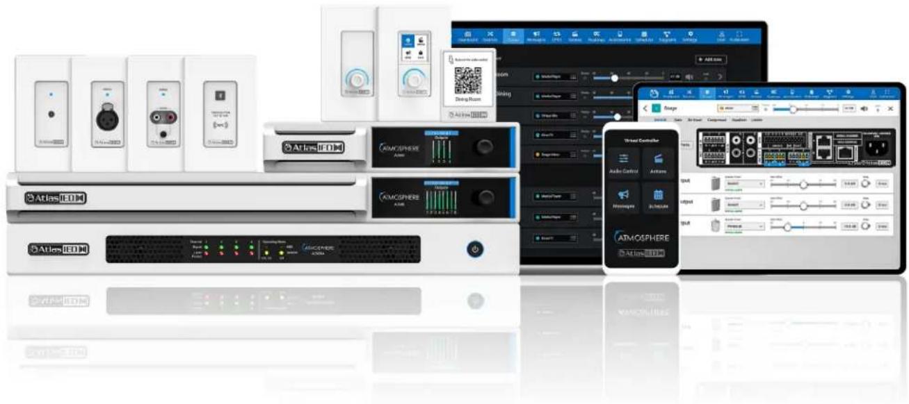
Atmosphere™ Next-Gen Expandable Zone DSP Controller
User Manual
Atmosphere
User Manual
Table of Contents
Important Safety Instructions....4
Introduction 5
Key Features and Applications....6
Package Contents 7
Rack Installation Guide 8
Hardware Overview 9
AZM4 & AZM8 Front Panel 10
AZM8 Back Panel 10
AZM4 Back Panel 10
Connections 12
Cabling....12
Network Connection Overview....13
Connecting Network Devices for Configuration....13
Method 1 - Ethernet Wired Connection .... 13
Method 2 - WiFi Connection .... 13
Method 3 - Access Point Connection....14
Software Overview 14
Dashboard 14
Features 14
Sources 15
ADD SOURCE - Mic/Line Inputs (Sources) 15
Source Settings-General - Mic/Line - Mono 16
General Settings-RCA Inputs - Mono 17
Stereo Sources - Mic/Line - Stereo 17
RCA Inputs - Stereo 18
Sources - DSP 18
Gate 18
De-Esser 19
Compressor 20
Equalizer - Presets 21
Auto-Gain Control....22
Audio Wall Plate Accessories (Sources) 23
Audio Wall Plate (ADD SOURCE) Inputs 24
General Settings for A-XLR Page 24
General Settings for A-RCA Page 25
General Settings for A-BT Page 26
How to Pair the A-BT Wall Plate 26
Mixes Overview – ADD MIX Setup 27
Input Mix Page 27
Signal Generator Input....28
Zones (Zone Outputs) 28
Zone- Mono-General Settings Page 29
Zone- Stereo + Sub - General Settings Page 29
Zone-Priority Page 30
Zone-Crossover Page 30
Zone-Equalizer 31
Ambient Noise Compensation - ANC 32
ANC – Auto Mode 33
Ambient Noise Sensor - X-ANS 33
Ambient Noise Sensor Placement Guide 33
Rule-1 34
Rule-2 34
Rule-3 35
Rule-4 35
Rule-5 36
Atmosphere
User Manual
Zones-Limiter 37
Zones-Groups Overview 38
Room Combine Active 39
Message Player Overview 40
Messages....40
Audio Files 41
Priority 41
GPIO Overview 42
GPIO Inputs 42
Setting Up a GPIO to Recall a Scene and/or Play a Message 42
GPIO Outputs and Presets (GPO's) 43
GPIO High Priority - Set Up GPIO to play a Message....44
Scenes Overview 45
Setting Up a Scene 45
Routines Overview 46
Setting Up a Routine 46
Accessories Overview 47
Control Accessories 47
Accessories Page 48
Setting Up a Virtual Wall Controller, General Settings, Audio Control 49
Virtual Mobile Device-Audio Control, Messages, Actions, Mobile Device 50
Print, Assemble, Place, and Scan....52
Setting Up Accessory Port Wall Controllers 53
C-ZSV General Settings 53
Audio Control....54
Messages....55
Actions 55
Screen Settings....56
Light Ring Settings 56
C-V General Settings 57
Audio Control....58
Light Ring 58
X-ANS General Settings 59
Accessories Connection Rules 59,60
Scheduler, Steps to Create an Event 61
Calendar-Bells 62
Calendar-Set up Bells & Schedule Exceptions 63
Diagrams – Connection Diagram and Block Diagram 64
Settings Page Overview 65
Configurations – Import-Export Settings 65
Network, Firmware 66
Device Settings, Clock 67
Event Log, User Account 68
Project Settings, Theme 69
Front Panel Display Menu Tree 70
Specifications....71,72,73
Mechanical Line Drawings with Dimensions 74,75
Regulatory Information: AZM4 / AZM8 / A-BT 77
Compliance Certs/FCC Statement 78
Limited Warranty, Customer Service Online Warranty Claim Process 79
Atmosphere
User Manual
Important Safety Instructions
CAUTION
RISK OF ELECTRIC SHOCK DO NOT OPEN
RISQUE DE CHOC ELECTRIQUE NE PAS OUVRIR

TO REDUCE THE RISK OF ELECTRIC SHOCK DO NOT REMOVE COVER (OR BACK)
NO USER SERVICEABLE PARTS INSIDE REFER SERVICING TO QUALIFIED PERSONNEL
Labeling on products and the Installation Instructions & User Manual may use safety related graphical symbols as shown below to note safety requirements.
Lightning Bolt: lightning flash with arrowhead symbol, within an equilateral triangle, WARNING symbol, is intended to alert the user to the presence of un-insulated dangerous voltage within the product's enclosure that may be sufficient in magnitude to constitute a risk of electric shock to persons or domestic animals.
ExplanationPoint: The exclamation point within an equilateral triangle, CAUTION symbol, is intended to alert the user to the presence of important operating and maintenance (servicing) instructions, or a hazard that can damage equipment.
To not proceed beyond a WARNING or CAUTION notice until you have understood the hazardous condition and have taken appropriate steps.
Ae continuez pas avant d'avoir pris connaissance du danger et prendre les mesures appropriées.
- Read these instructions.
- Keep these instructions.
- Heed all warnings.
- Follow all instructions.
- Do not use this device near water.
- Clean only with dry cloth.
- Do not block any ventilation openings. Install in accordance with the manufacturer's instructions.
- Do not install near any heat sources such as radiators, heat registers, stoves, or other device that produce heat.
- This product is equipped with a three-wire grounding-type plug, a plug having a third (grounding) pin. This plug will only fit into a grounding-type power outlet. This is a safety feature. If you are unable to insert the plug into the outlet, contact your electrician to replace your obsolete outlet. Do not defeat the safety purpose of the grounding-type plug.
- To completely disconnect this equipment from the mains, disconnect the power supply cord plug from the receptacle.
- The mains plug of the power supply cord shall remain readily operable.
-
Protect the power cord from being walked on or pinched particularly at plugs, convenience receptacles, and the point where they exit from the device.
-
Only use attachments / accessories specified by the manufacturer.
-
Use only with the cart, stand, tripod, bracket, or table specified by the manufacturer, or sold with the device. When a cart is used, use caution when moving the cart / device combination to avoid injury from tip-over.

-
Unplug this device during lightning storms or when unused for long periods of time.
-
Refer all servicing to qualified service personnel. Servicing is required when the device has been damaged in any way, such as power-supply cord or plug is damaged, liquid has been spilled, or objects have fallen into the device, the device has been exposed to rain or moisture, does not operate normally, or has been dropped.
WARNING: To reduce the risk of fire or electric shock, do not expose this apparatus to rain, moisture, dripping, splashing, or place objects filled with liquids on the equipment.
WARNING: If apparatus is equipped with Class I grounding plugs for safety purposes, it must be connected to MAINS that employ a protective earth ground connection.
WARNING: The MAINS plug on this device may be used as the DISCONNECT DEVICE for MAINS power and must remain readily operable.
WARNING: Installation and maintenance of AtlasIED equipment is to be made by trained / qualified personnel and must conform to all applicable local codes.
WARNING: If unit contains a lithium battery, there is a danger of explosion. Replace only with the same or equivalent type.
WEEE NOTICE: This appliance is labeled in accordance with European Directive 2012/19/EU concerning waste of electrical and electronic equipment (WEEE). This label indicates that this product should not be disposed of with household waste. It should be deposited at an appropriate facility to enable recovery and recycling.
Atmosphere
User Manual
Introduction
The Atmosphere platform consists of 2x signal processors, 6x accessories, 2x amplifiers, integrated controlling software, integrated message player, loads of features, a few patents, and a commitment that this is only the beginning for Atmosphere. Thank you for purchasing our Atmosphere platform, and congratulations, you have made a solid long-term investment in quality audio. In our rapidly changing technology-rich world, providing customers with long-term stability, scalability, and flexibility are paramount. From all of us at AtlasIED, we once again thank you for your purchase and look forward to working with you in the future.
Inputs and Outputs
The AZM4 features a 6 input / 4 output configuration with 4 mic/line and 2 RCA stereo summed inputs and 4 output zones. In addition, 2 RJ45 bus ports each allow for 1 audio wall plate accessory, A-XLR, A-RCA or A-BT, bringing the total input count to 8 by 4 out.
The AZM8 features a 10 input / 8 output configuration with 8 mic/line and 4 RCA stereo summed inputs and 8 output zones. In addition, 4 RJ45 bus ports each allow for 1 audio wall plate accessory, A-XLR, A-RCA or A-BT, bringing the total input count to 14 by 8 out.
Flexible Assortment of Smart Accessories with Self-Heal
Six plug and play smart Wall Plate accessories, unmatched in the industry, expand the AZM capabilities and allow for future scalability. Accessories include 3 x Audio Inputs; balanced Mic / Line XLR, dual RCA stereo summed with 3.5mm, and Bluetooth® audio wall plate inputs, 2 x Controllers; Volume Controls, Volume Controls with Source Select, Scene Recall, and Message Playback, and 1 x Ambient Noise Sensor for Ambient Noise Compensation control. Any control accessory can be daisy chained on a single cable digital bus and assigned to any zone, reducing installation wiring time and complexity. For additional peace of mind, turn on accessory "Self-Heal" after set-up. In the event an accessory wall plate become inoperable, field swap that wall plate with a new one and it will restore the settings to the new accessory without any re-programming required.
Configurable Mobile Device Control
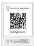
With the ability to turn any mobile device into a virtual "App-Less" zone controller by simply scanning a QR Code with a phone or tablet, Atmosphere mobile control is the easiest, most cost-effective way to provide zone control to the customer. Setup the type of control you want on the user's device, print QR codes directly from the settings page and mount in their respective zone using the X-GEM mounting frame.
Comprehensive Web User Interface with Dynamic Dashboard
Atmosphere features a user-friendly web-based User Interface (UI) controller with deep dive capabilities to meet the most expansive and complex of user requirements. Source inputs feature a full suite of DSP with dynamics like gates, de-esser, compressor, 4 band EQ, and auto-gain. Zone outputs have, 4-level priority ducking, crossover, 8-band EQ, automatic noise compensation, and limiter that splits for Sub + Main, with output speaker presets based on AtlasIED speaker models. Events can be scheduled in a familiar calendar format with a dashboard that displays the upcoming schedules events. Actions that include Scenes, Messages, GPO Presets, Bell Schedule Recall, Room Combine, can be scheduled or triggered by GPI's, UI, virtual, or mounted wall controllers. Continuous system monitoring is contained within a dashboard view to simplify oversight of all the functions.
Stereo and Subwoofer Support
AZM4 and AZM8 are now capable of seamlessly supporting stereo sources, stereo zones, and zones with subwoofers. When creating a source, choose between mono or stereo for that source. When creating a zone, choose between mono, mono+sub, stereo, and stereo+sub. Proper controls are automatically linked, appropriate DSP objects are created, etc. Features such as automatic ambient noise compensation continue to operate as expected and are compatible with new source and zone types.
Room Combine / Zone Grouping
In addition to the new zone types (stereo, subwoofer), two or more zones can now be combined to create a group. When grouped, the zones all share a common source and volume control. Individual zone volume offsets can be applied at commissioning as well as during runtime. The combined and uncombined state can be recalled via GPI, C-ZSV controller, virtual wall controller (mobile), scheduled events, and more.
Atmosphere
User Manual
Bell Scheduler
Great for education, industrial, and corporate markets, our bell scheduler allows for multiple bells, ring lists, and schedules to be created to support both pre-planned schedules as well as planned and unplanned exceptions. Initial setup is easy to follow and understand, all while providing all the tools for even the most complex of schedules. End user control is simple through either a wall controller, mobile controller, or with the new "Planner" user access level. A user with Planner access level has full control over adding, editing, deleting bells and other scheduled events such as Scenes, Messages, or Routines.
Actions and Triggers - Routines, Scenes
With the addition of Room Combine and Bell Scheduler, and to allow for easier management of system capabilities, Scenes has been simplified to only include zone/source/volume settings. Messages now reside in the Messages section, and logic output settings are managed through the new GPO Presets tab in the GPIO menu.
The AZM4 and AZM8 have numerous capabilities which are called Actions. An Action is defined as either a Scene, Message, GPO Preset, Bell Schedule Recall, or Room Combine. Each Action can be recalled by any one of a number of Triggers. A Trigger can either be the web UI, wall controller, virtual wall controlled, scheduled event, front panel control, or GPI (button press). Routines allow you to combine two or more actions, to be performed simultaneously. Setting up a Routine is as simple as choosing which Actions should be combined.
Expanded Mixing Capabilities
Each Atmosphere AZM allows up to 4 user defined sub-mixes. Each of the 4 mixes can mix any and all of the input sources together. That's all 14 inputs on AZM8 and all 10 on AZM4.
Key Features
• 4 (AZM4) & 8 (AZM8) – Independently Controlled Zone Models
- Web UI – Designed for Optimal Use with Chrome or Safari Web Browsers
- Plug and Play Intelligent Wall Plate Accessories
- Daisy Chain up to 8 Accessories per Port, 2 Ports on AZM4, 4 Ports on AZM8
• Adaptive Ambient Noise Sensor Accessory
- Accessory Data + Audio Digital Bus - RJ45-Cat 5e/6 Wire Runs Up to 1000ft
• Input Auto-Gain Audio Control
• Virtual Wall Controllers for Mobile Devices, with QR Code Set-up; No App Required
- Tilter-Filter Room EQ Adjustment Tool
- AtlasIED Speaker Presets
• Mono, Mono + Sub, Stereo, Stereo + Sub support - Intuitive Calendar Format Event Scheduler
- Bell Scheduler
- Integrated .wav File Message Player with On-board Storage
- Room Combine
- 12 x GPI with Hi-Priority port and 2 x GPO with Presets
• Printable Dynamic System Diagram
• Simple, Streamlined Workflow for All Skill Levels
Applications
- Restaurant-Bars
- Hospitality Suites
• Houses of Worship • Medical Centers - Offices/ Lobbies
- Education
- Industrial
- Industrial
• Corporate Centers

Atlas IED
1601 JACK MCKAY BLVD.
ENNIS, TEXAS 75119 U.S.A.
TELEPHONE: (800) 876-3333
SUPPORT@ATLASIED.COM
AtlasIED.com
Atmosphere
User Manual
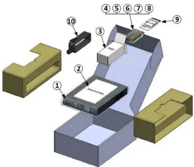
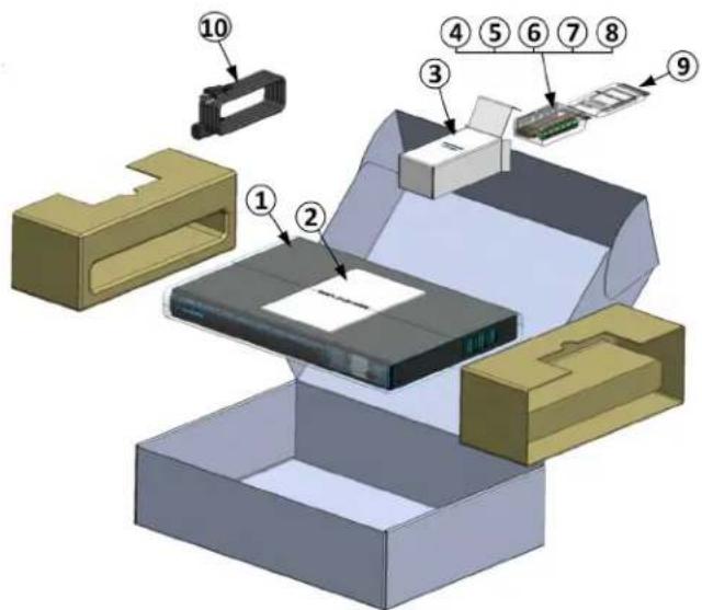
Package Contents
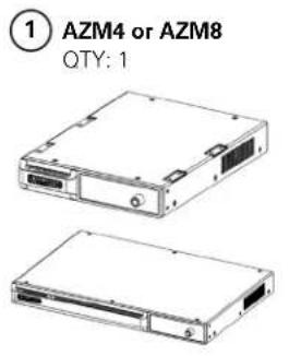
natural_image
Two views of an electronic device labeled AZM4 or AZM8, showing front and side views (no text beyond labels)
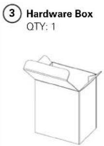
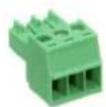
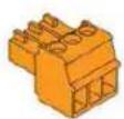
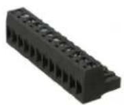
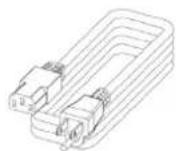
AZM4 AZM8

Atlas IED
1601 JACK MCKAY BLVD. ENNIS, TEXAS 75119 U.S.A.
TELEPHONE: (800) 876-3333 SUPPORT@ATLASIED.COM
AtlasIED.com
Atmosphere
User Manual
Rack Installation Guide
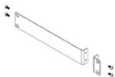
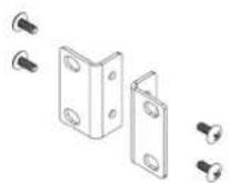
To rack mount the AZM8, remove included rack ears and fasteners from hardware box and attach to each side.
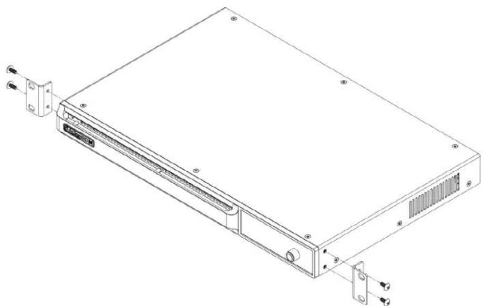
natural_image
Technical line drawing of a server rack with mounting bracket and ports (no text or symbols)To rack mount the AZM4, remove included rack ear and 12 rack adapter and fasteners from hardware box and attach to each side.

natural_image
Technical line drawing of an electronic device chassis with mounting brackets and connectors (no text or symbols)Note: The AZM4 is a 1/2-RU device and can be mounted in a side-by-side configuration using the AtlasIED part # PA702-RMK rack kit. It can also be combined with the IP power strip AtlasIED AP-S15HRIP.
Note: When rack mounting the AZM, the fan air flow is from front to back.

Atlas IED
1601 JACK MCKAY BLVD.
ENNIS, TEXAS 75119 U.S.A.
TELEPHONE: (800) 876-3333
SUPPORT@ATLASIED.COM
AtlasIED.com
Atmosphere
User Manual
Hardware Overview
AZM4 and AZM8 Front Panel
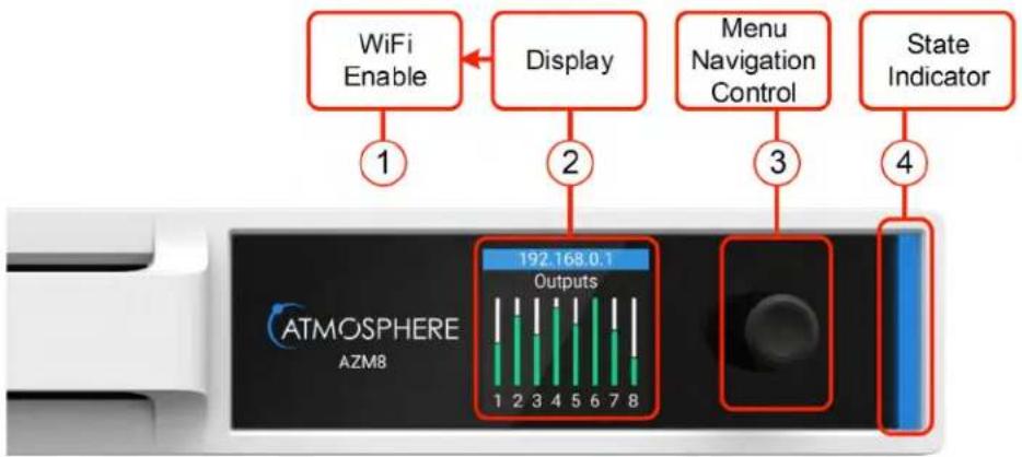
1. WiFi Enable
Out of the box, the AZM is configured to connect to an existing network via the back panel ethernet port. However, there are two additional methods for connecting to the AZM for configuration, WiFi or Access Point mode, enabled from the front panel menu. If no existing network is available, it is recommended that the onboard WiFi (Access Point mode) be used for initial configuration.
2. Display
The Display is a multi-functional status interrogator and visual activity monitor. It is designed to provide "quick look" verification of selections when in front of the unit and when the UI is not handy. It also allows configuration of network (ethernet, WiFi, and access point) settings.
When first powering the AZM, the Display will show the IP address and the Outputs activity. At the bottom is the Menu > Navigation. Pressing the Navigation control knob will step thru the menu tree in the following order:
- Zone Control – Change sources, volumes, and mute state in any zone. The user can also recall Actions. This has to be configured within the UI before access is given.
- Network – See network status and settings; change mode between access point, WiFi, ethernet; change connection to available networks by signal strength, enter SSID.
• I/O Signals – Select Inputs or Outputs individually and see signal activity. - Accessories – See Accessories connected to Ports A, B, (AZM4) and A, B, C, or D (AZM8) select and read specific menu of Accessory and find location.
- Faults -- Displays "Live" fault events only. (Live faults also cause the light base to flash red.) To clear a live fault, you must resolve the issue. Example: If two audio accessories (A-XLR, A-RCA, or A-BT) are plugged into the same bus-port, the "fault" appears in the menus and will lead you to the description of the fault. In this example, the fault doesn't go away until one of the two audio accessories on the port is unplugged or removed. It can take up to 30 seconds to clear the display after correcting the fault.
- Sensor Data – Read temperature sensor data from I/O; CPU; PSU (power supply unit).
- System Clock – Read Time/Date; refresh NTP.
- Firmware Info – Read current firmware version and last updated Date/Time.
- Lock – Lock/Unlock menu display.
3. Navigation Control & Factory Reset
To cycle through display menus, press knob. To select an option, turn to move cursor & press.
To Factory Reset unit from the front panel, remove power and re-power, then press and hold front panel Navigation Control within 60 seconds.
Note: To save Settings prior to Factory Reset, go to Settings, Configurations and Save file to computer for upload after reset. When left undisturbed for 60 secs, the display will return to the default = Outputs.

Atlas IED
1601 JACK MCKAY BLVD.
ENNIS, TEXAS 75119 U.S.A.
TELEPHONE: (800) 876-3333
SUPPORT@ATLASIED.COM
AtlasIED.com
Atmosphere
User Manual
4. Light Bar System "State" Indicator
This indicator monitors the current state of the AZM.
• Blue = Unit powered ON and operating properly
• Flash RED = Live Fault is detected
If a Fault is indicated, use the Menu Display to navigate to "Faults", and evaluate the source of the problem, or go to the UI Dashboard and see Faults for specific cause. Fault is only cleared after resolving the issue. Typical issues that will trigger a Live Fault condition are:
- "Port Wall Plate Overload" – Too many controllers on the port.
- "Port Audio Wall Plate Overload" – More than one audio Wall Plate is on a single port.
- "Product Wall Plate Overload" – too many Wall Plates plugged into the AZM.
- "Backwards Audio Error" – Audio Wall Plate connected backwards.
- "Critical Temp Error" – Temperature exceeds maximum acceptable value.
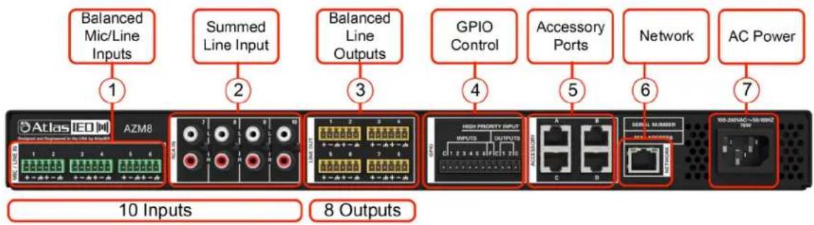
AZM8 Back Panel
flowchart
graph LR
    A["AT&T I/O"] -->|1 Balanced Mic/Line Inputs| B["AZM8"]
    B -->|2 Summed Line Input| C["GPIO Control"]
    C -->|3 Balanced Line Outputs| D["HISH PROPERTY INPUTS"]
    D -->|4 Accessory Ports| E["Network"]
    E -->|5 Accessory Ports| F["AC Power"]
    F -->|6 Network| G["Signal Numberer"]
    G -->|7 AC Power| H["AC Power"]
    style A fill:#f9f,stroke:#333
    style B fill:#ccf,stroke:#333
    style C fill:#cfc,stroke:#333
    style D fill:#fcc,stroke:#333
    style E fill:#cff,stroke:#333
    style F fill:#ffc,stroke:#333
    style G fill:#cfc,stroke:#333
    style H fill:#fcc,stroke:#333
AZM4 Back Panel
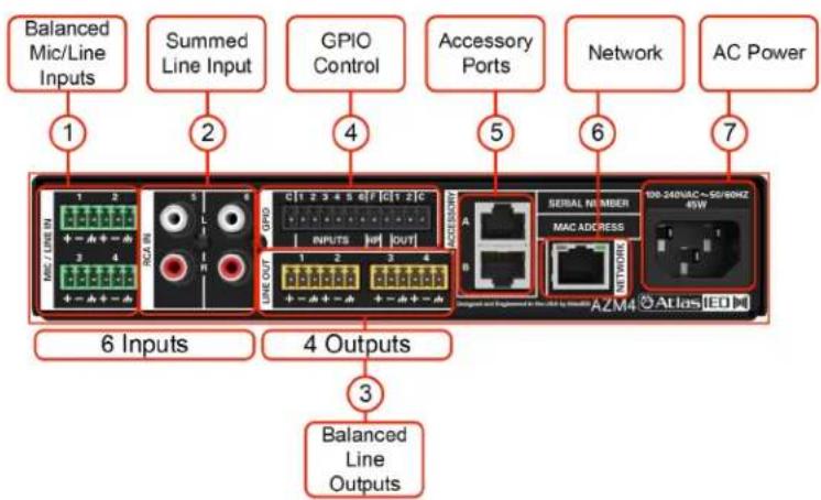
1. Balanced Mic/Line Inputs
Inputs 1-4 (AZM4) and 1-6 (AZM8) accept balanced input signals via the removable 3.5mm Phoenix type connector. For wiring, follow the labeling on the rear of the AZM. For unbalanced signals, connect the (-) and (GND) pins together. Note: DSP configuration and zone assigning are done in the UI. Any Source Input can be assigned to any Zone Output.
2. Summed Line Inputs
Inputs 5-6 (AZM4) and 7-10 (AZM8) accept standard stereo RCA Line level source devices (media players or computers) and are summed to mono internally for assigning to zones.

Atlas IED
1601 JACK MCKAY BLVD.
ENNIS, TEXAS 75119 U.S.A.
TELEPHONE: (800) 876-3333
SUPPORT@ATLASIED.COM
AtlasIED.com
Atmosphere
User Manual
3. Balanced Line Outputs
Zone outputs 1-4 (AZM4) or 1-8 (AZM8) are to connect to balanced line inputs, primarily for amplifiers, such as the Atmosphere AZA amplifiers, that power zone speakers.
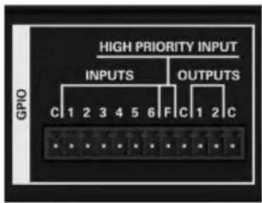
4. GPIO (General Purpose Input Output Ports)
The 3.5mm 12-way GPIO Euro block contains:
- 3 x Common "C" – these are all tied to common and can be used for any terminal wiring.
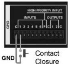
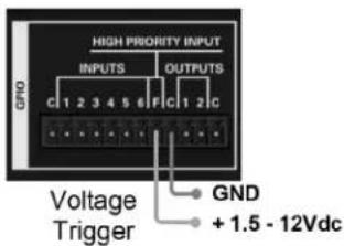
- 6 x (1 - 6) control inputs – configured individually in the UI as CC (Contact Closure) (Normally Open) or 1.5-12Vdc trigger.
The 6 control inputs can:
- Recall a routine
- Recall a scene
- Trigger message playback
- Run a bell schedule
- Trigger a GPO preset
- Combine room
- 1 x Terminal "F" High Priority "HP" input function.
The High-Priority input can:
- Mute all zones
- Set all zones and group levels
- Lock and alert accessory controllers
- Play a message one time or on a repeated basis
- 2 (GPO-1 & GPO-2) Control Outputs - Voltage triggers are individually named and assignable in GPIO Outputs page and configured in Output Presets page. The Output Presets page includes 5 types of voltage trigger settings that can be configured: Logic H, Logic L, Toggle, Pulse H, and Pulse L, along with adjustable Pulse Time from .1-10.0 sec, a common "C" terminal for output ports 1 & 2 for external equipment interfacing.
5. Accessory Ports
RJ45 (not-Ethernet) bus-ports A & B (AZM4) or A, B, C & D (AZM8) are used for connecting
Atmosphere Plug and Play accessories. All accessories are recognized by the UI automatically when plugged in and can be assigned to any zone. Multiple bus-ports are provided to allow more accessories to be used and to make it easier for installers to create cable homeruns.
To guarantee good performance of all connected accessories, follow these rules:
- Use CAT5e or CAT6 (non-shield) cable to connect accessories to the host processor bus-port.
- Up to 8 Accessories can be daisy chained from a single port.
- Up to 16 Accessories can be connected to a single AZM, (AZM4 or AZM8).
- The maximum cable length from the AZM to the last accessory on the chain is 1000'(305m).
- One Audio Wall Plate (A-XLR, A-RCA, A-BT) can be used per bus-port.
Note: See "Plug and Play Accessories Connection Rules" for more details.
Note: A maximum of 8 X-ANS accessories can be used per AZM.
6. Network
Connect to LAN where device is installed. The AZM default IP is set to DHCP and, when terminated to a router with DHCP enabled, will display the IP address on the front panel display.
7. AC Power
AC Power Input – IEC connector, 100-240VAC \~ 50-60 Hz, universal power supply.
Atmosphere
User Manual
Connections
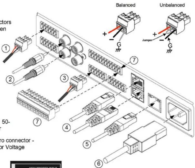
① 3-Pin 3.5mm Euro Connectors for Balanced Inputs – Green
② Dual RCA for media sources - Summed Left-Right Line Input
③ 3-Pin 3.5mm Euro Connectors for Balanced Outputs – Orange
④ RJ45/Cat5E-Cat6 for Accessories
⑤ RJ45/Cat5E-Cat6 for Network
⑥ AC Mains – 100-240VAC, 50-60 Hz, with IEC connector
⑦ GPIO - 12 Pin 3.5mm Euro connector - Contact Closure Pull low or Voltage Trigger assigned in UI.
Cabling
Balanced Inputs & Outputs - Use of 2 conductor w/shield for low level signals of 20-22 gauge is best. Maintain the proper polarity, + to +, - to - and shield to ground. Note: When using an unbalanced source on the 3.5mm Euro Connector, connect the GND to - with a jumper wire. (see unbalanced image in connections guide).
For the RCA inputs, pre-made RCA cables can be purchased from AtlasIED to simplify interconnection to external devices.
https://www.atlasied.com/volume-controls-cables-audio-cables-unbalanced-audio
For RJ45 connections, use CAT5e or CAT6 (non-shield) network cable with T-568B or A wiring. Pre-made network cables must be pin-to-pin. Do not use cross-over network cables. Always use best practices while terminating RJ45s to cables, keeping pairs twisted up to the connector. Avoid tight bends and kinks in the wire path. Note: Pre-made cables may be more difficult to fit in back boxes when used with accessory wall plates. See line drawings with dimensions in the back of this manual for depth consideration.

Atlas IED
1601 JACK MCKAY BLVD.
ENNIS, TEXAS 75119 U.S.A.
TELEPHONE: (800) 876-3333
SUPPORT@ATLASIED.COM
AtlasIED.com
Atmosphere
User Manual
Network Connection Overview
Connecting Devices to the AZM for Configuration
Out of the box, the AZM is configured to connect to an existing network via the back panel ethernet port. However, there are two additional methods for connecting to the AZM for configuration. If no existing network is available, it is recommended that the onboard WiFi Access Point (Method -#3) be used for initial configuration.
Method-1 - Ethernet Connection (Wired connection)

flowchart
graph LR
    A["Device 1"] -->|USB| B["Port 1"]
    A -->|USB| C["Port 2"]
    A -->|USB| D["Port 3"]
    A -->|USB| E["Port 4"]
    A -->|USB| F["Port 5"]
    A -->|USB| G["Port 6"]
    A -->|USB| H["Port 7"]
    A -->|USB| I["Port 8"]
    A -->|USB| J["Port 9"]
    A -->|USB| K["Port 10"]
    A -->|USB| L["Port 11"]
    A -->|USB| M["Port 12"]
    A -->|USB| N["Port 13"]
    A -->|USB| O["Port 14"]
    A -->|USB| P["Port 15"]
    A -->|USB| Q["Port 16"]
    A -->|USB| R["Port 17"]
    A -->|USB| S["Port 18"]
    A -->|USB| T["Port 19"]
    A -->|USB| U["Port 20"]
    A -->|USB| V["Port 21"]
    A -->|USB| W["Port 22"]
    A -->|USB| X["Port 23"]
    A -->|USB| Y["Port 24"]
    A -->|USB| Z["Port 25"]
Connect an RJ45 cable (CAT5e or CAT6) from the AZM ethernet port to an existing network.
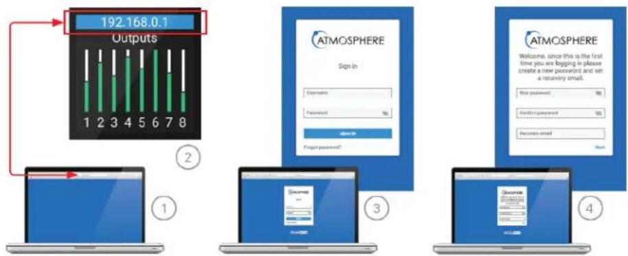
Logging in to the AZM:
- Open web browser on device that is on the same network as the AZM.
- Navigate to the IP address shown on the front panel of the AZM using the web browser address bar.
- Login using the username "admin" and password "admin."
- After the first login, follow the onscreen instructions to change the default log in credentials.
flowchart
graph TD
    A["Outputs 192.168.0.1"] --> B["ATMOSPHERE Sign in"]
    B --> C["Login: Subscribe, Password: ✓"]
    C --> D["Confirm: ✓"]
    D --> E["ATMOSPHERE Welcome: New password, Send to password, Recycle email"]
Method-2 - WiFi Connection (Connect to existing wireless network)

- From the front panel menu enable WiFi mode (Network>WiFi>Change Mode>WiFi, then confirm change).
- Select the WiFi network you would like to connect to (Network>WiFi>WiFi Networks).
- Enter the password and then select the green checkmark to connect to the network.
Note: The WiFi connection can be set up in the user interface if the AZM is connected via the ethernet port.

Atlas IED
1601 JACK MCKAY BLVD.
ENNIS, TEXAS 75119 U.S.A.
TELEPHONE: (800) 876-3333
SUPPORT@ATLASIED.COM
AtlasIED.com
Atmosphere
User Manual
Method-3 - Access Point Connection (Built-in WiFi creates a local wireless network for connection)

• From the front panel menu enable Access Point Mode (Network>WiFi>Change Mode>Access Pt, then confirm change).
• The unit will now broadcast an SSID (AtlasIED_AZM will be the default SSID) that can be found using WiFi enabled devices.
- Select the now available network from the settings page on your device and connect. (The default password is AtlasLED. This can be changed in the user interface).
- Using a web browser on the device, navigate to the IP address that appears on the AZM front panel screen using the address bar located in the web browser.
Software Overview (in order of toolbar, left to right)
Dashboard
The Dashboard is the user page to monitor the AZM system wide activity. It provides quick links to interrogate and fix settings.
Features
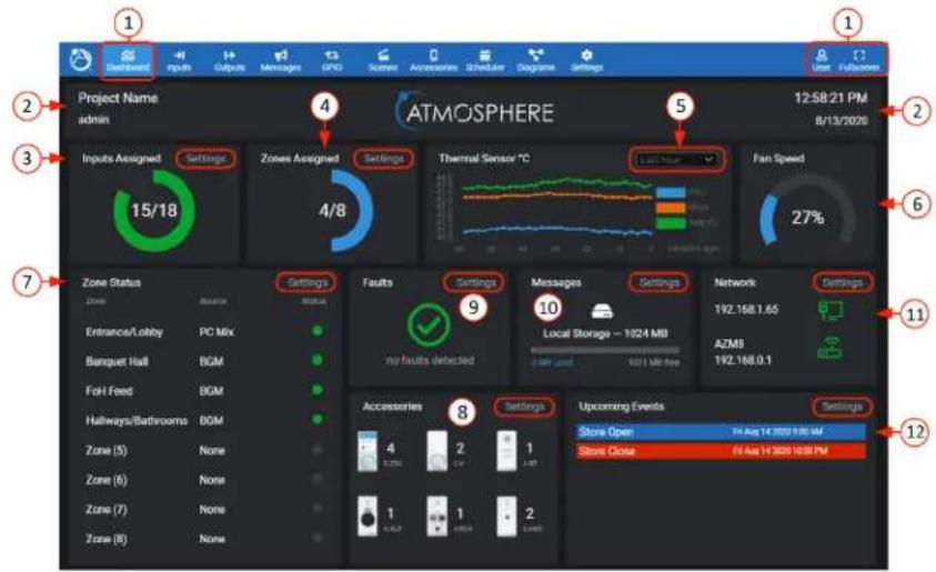
- The Dashboard is the first tool on the UI navigation toolbar. Select to open. To the far right, there is a User link to settings page, and an option for Full Screen view, if desired. The background has a dark or light Theme setting that can be selected when logging in or otherwise selected in settings under the Theme page.
- This area displays the project and user's name that is entered under the settings toolbar on the Project Settings page to the left. On the right, the Time & Date is also set up under the settings toolbar on the Clock Settings page.
-
Input Sources Assigned - displays a Green LED style indicator for each of the inputs routed to a zone. An input source will also be counted as consumed if it has been given a name or is part of a scene.
-
Zones Assigned - displays a Blue LED style indicator for each of the zone outputs that are assigned to a source.
-
Thermal Sensor – this is the output of the three monitored heat sensors: PSU (power supply unit), Micro (microprocessor), and Analog I/O. The read-out can be viewed by Last Hour, Last Day, Last Week, or Last Month.
- An internal fan will turn on automatically if necessary and speed is displayed as a visual graphic and corresponding percent. Fan speed is dynamically regulated by monitoring temperature. The airflow direction is front to rear.

Atlas IED
1601 JACK MCKAY BLVD.
ENNIS, TEXAS 75119 U.S.A.
TELEPHONE: (800) 876-3333
SUPPORT@ATLASIED.COM
AtlasIED.com
Atmosphere
User Manual
- Zone Status - displays the activity of each zone output, what source feeds them, and active bar graph style indicator; Blue = signal activity, Red = clipping. A quick link “>” to each of the Zones' settings is at the right side of the area.
- Accessories, when connected on any of the A-B-C-D Bus-ports, will be automatically detected by the AZM. When detected, the accessory image will be displayed on this page by type and quantity. There is also a quick link to the Accessories page.
- Notifications - will display as an exclamation mark when a fault condition is active and a green checkmark when there are no active faults. The settings link will take you to the Event Log UI page to interrogate and resolve the fault issue.
- Message Player Status – when no message is playing, shows "available memory" for message uploads. Click Settings link ">” to go to Message Page. When a message is playing – a bold Cancel button displays, to stop the message if necessary. The file name and length/progress bar with elapsed time will indicate progress of current message playing.
- Network displays the IP address and status of the WiFi and wired connections. The AZM can be connected to both WiFi and wired connections at the same time using two IP addresses. Settings link “>” navigates to the Network Setup page.
- Upcoming Scheduled Events along with the current Bell Schedule will be listed in this display. The quick link “>” navigates to the Event Scheduler page.
Sources
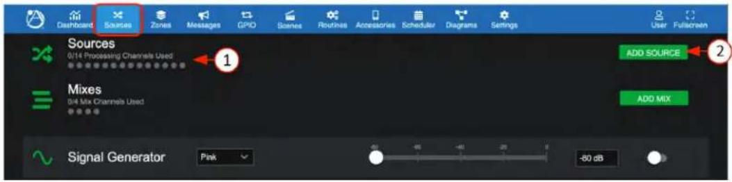
The Sources page is where you add or delete and configure the types of input sources available: Mic/Line inputs, RCA inputs, Audio Wall Plate Accessory inputs, Mixes (Group Mix) inputs, and Signal Generator input. Input sources can also be mono or stereo.
Add Source - Mic/Line Inputs
↑
- The Sources display lights a green LED style status indicator for each input source channel as it is assigned to an input port. When you first open the Sources tab, you begin by selecting and configuring each of the input sources in your project.
- Select "Add Source" to open the configuration popup and begin configuring your sources.
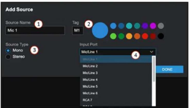
- Each source input can be named and will be added to the inputs selection list as well as populate the name on all other respective inputs system wide, including the printable connections diagram.
- A letter or numeric tag and color can be selected to enhance visualization identity of source types.
- Source type can be mono or stereo. Select prior to assigning the input port.
- Select the input port or, if stereo, input ports (left/right) from the drop-down list of available inputs and select OK to add the source to the sources list.

Atlas IED
1601 JACK MCKAY BLVD.
ENNIS, TEXAS 75119 U.S.A.
TELEPHONE: (800) 876-3333
SUPPORT@ATLASIED.COM
AtlasIED.com
Atmosphere
User Manual
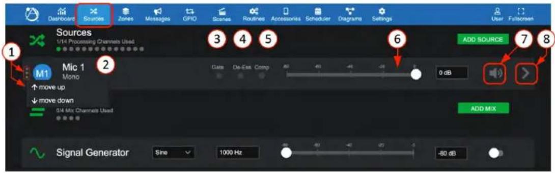
- The configured mono source named "Mic-1" is displayed. As the list of input sources grows, the order can be sorted by selecting the Move Up/Down icon at left.
- Sources shows one of 14 (AZM8) green LED style indicator for each input source that is assigned to an input port.
- "Gate" status indicator shows: Yellow = active (gate closed), Gray = gate open.
- "De-Ess" status indicator shows: Yellow = the compressor in the De-Esser is compressing, Gray = no compression in the De-Esser.
- "Comp" status indicator shows: Yellow = compressor is compressing, Gray = compressor is not compressing.
- Input Level adjust - move fader or enter the desired dB level in window. When signal is present, fader animates as a pre-fader peak meter and shows: Green = signal activity, Red = clipping.
- Mute – Select to toggle mute state on/off.
- Where the “>” icon is visible, it represents the settings link, in this case the Mic/Line Input Settings, and opens the General Settings page, along with the DSP sub Tabs for: Gate, De-Esser, Compressor, Equalizer, Auto-Gain. All input sources have the same DSP sub-Tab pages.
Source Settings-General
Mic/Line-Mono
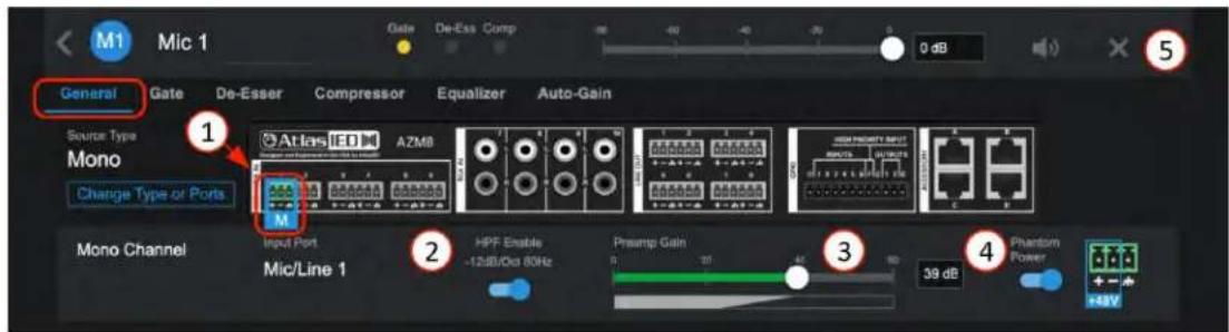
- Mic/Line sources identify the input port selected.
- Pre-set High Pass Filter Enable – a separate EQ filter placed before the Equalizer page allowing roll-off of low end before the gate and compressor, allowing all bands of the equalizer to be used for other requirements. NOTE: In Stereo Mode, the DSP will affect both left & right channels.
- 0dB to +60 dB of preamp gain available to fine tune input sensitivity.
- Phantom power enable with voltage on pins identified for wiring.
- When in the General Settings page, editing of the source name, color tag (click on color), and also delete source "X", is available.

Atlas IED
1601 JACK MCKAY BLVD.
ENNIS, TEXAS 75119 U.S.A.
TELEPHONE: (800) 876-3333
SUPPORT@ATLASIED.COM
AtlasIED.com
Atmosphere
User Manual
RCA Inputs - Mono
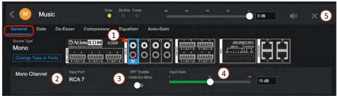
- Displays rear panel and identifies physical location of the RCA mono-summed input for wiring. Navigation tabs for Gate, De-Esser, Compressor, Equalizer, and Auto-Gain. (same as Mic/Line).
- Shows input type and port select, "Change Type or Ports" to re-configure if desired.
- Pre-set High Pass Filter Enable – a separate EQ filter placed before the Equalizer page allowing roll-off of low end before the gate and compressor, allowing all bands of the equalizer to be used for other requirements.
- 0dB to +30 dB of preamp gain available to fine tune RCA input sensitivity sources.
- When in the General Settings page, editing of the source name, color tag (click on color), and also delete source "X", is available.
Stereo Sources
Mic/Line - Stereo
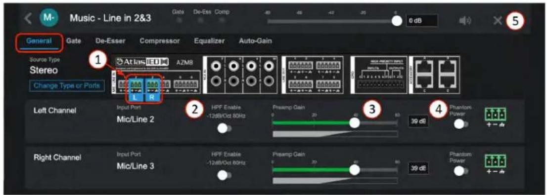
- Mic/Line Stereo sources require selecting a Left and Right input port which can be any available Mic/Line Inputs.
- Pre-set High Pass Filter Enable for Left & Right – a separate EQ filter placed before the Equalizer page allowing roll-off of low end before the gate and compressor, allowing all bands of the equalizer to be used for other requirements. NOTE: In Stereo Mode, the DSP will affect both left & right channels automatically.
- 0dB to +60 dB of preamp gain available to fine tune input sensitivity.
- When in the General Settings page, editing of the source name, color tag (click on color), and also delete source "X", is available.

Atlas IED
1601 JACK MCKAY BLVD.
ENNIS, TEXAS 75119 U.S.A.
TELEPHONE: (800) 876-3333
SUPPORT@ATLASIED.COM
AtlasIED.com
Atmosphere
User Manual
RCA Inputs - Stereo
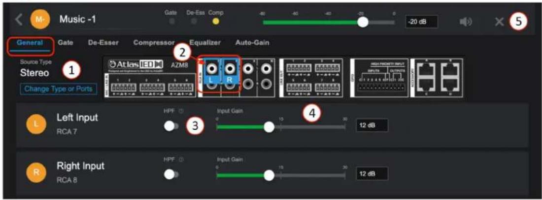
- Stereo sources require selecting a Left and Right input port which requires using two RCA Inputs.
- Using the stereo-summed RCA inputs requires splitting the Left/Right RCA cable between two input ports for true Left/Right stereo. (In this example, the Left + to + input 7 and Right - to + input 8)
- Pre-set High Pass Filter Enable for Left & Right – a separate EQ filter placed before the Equalizer page allowing roll-off of low end before the gate and compressor, allowing all bands of the equalizer to be used for other requirements. NOTE: In Stereo Mode, the DSP will affect both left & right channels.
- 0dB to +30 dB of preamp gain available to fine tune RCA input sensitivity sources.
- When in the General Settings page, editing of the source name, color tag (click on color), and also delete source "X", is available.
Sources - DSP
Gate
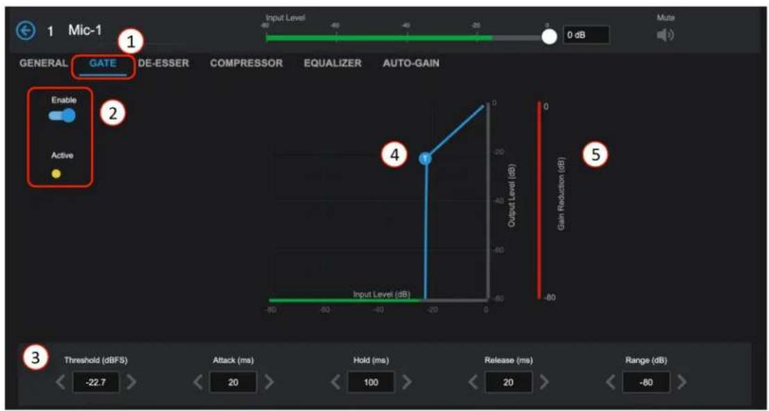
- Gates, sometimes referred to as Noise-Gates, are typically used to reduce noise from an open microphone when placed in a noisy environment by turning off or reducing the gain until the intended signal is present. The signal must reach the threshold setting to open the Gate and allow the mic to be heard. When the signal goes below the threshold, the Gate closes again. A common use for this feature is when making announcements in noisy rooms. The Gate can be adjusted to keep the mic muted until someone walks up and speaks directly into it, thereby reducing the PA system from amplifying the crowd chatter.
- Enable the Gate and Active indicator.

Atlas IED
1601 JACK MCKAY BLVD.
ENNIS, TEXAS 75119 U.S.A.
TELEPHONE: (800) 876-3333
SUPPORT@ATLASIED.COM
AtlasIED.com
Atmosphere
User Manual
- The dynamic settings can be adjusted with left or right arrows or by entering the desired number. The dynamic settings are defined as follows:
• Threshold: the signal level required to engage the Gate.
- Attack Time: amount of time to fully engage (Gate, De-Esser, Compressor, Limiter) after signal level increases beyond the threshold.
- Hold Time: amount of time (Gate, De-Esser, Compressor, Limiter) is held after the signal level decreases below the threshold.
- Release Time: amount of time to fully disengage (Gate, De-Esser, Compressor, Limiter) after hold time has expired.
-
Range: amount of gain reduction where -100 is totally off.
-
Graphic display of settings, the "T" is the Threshold that can be dynamically adjusted with a mouse.
-
The Gain Reduction (Range setting) shows Red when the Gate is engaging. In this example, the Gate is effectively shut because the signal is below the Threshold setting required to open it.
De-Esser
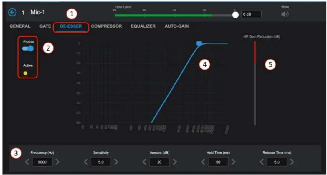
- De-Essers are used when a high frequency (around 5000Hz) sibilance (S-sounds) are too pronounced in speech. The objective is to reduce the sibilance at the frequency where it is too loud.
- Enable the De-Esser and Active indicator.
- Settings: Frequency (Hz), Sensitivity, Amount (dB), Hold Time (ms), Release Time (ms)
• Frequency: the target frequency where the sibilance (S-sounds) is most pronounced.
- Sensitivity: how much level at the target frequency is required to engage De-Esser.
• Amount: amount of gain reduction applied after De-Esser engages.
- Hold Time: amount of time the De-Esser is held after the signal level decreases below the sensitivity setting.
- Release Time: amount of time to fully disengage after hold time has expired.
Example method of setting a De-Esser:
First find the Frequency where the sibilance is worse case; start around 5KHz and move up/down with the "Amount" set high, +20dB or more to emphasize issue. When the problem area is found, adjust the sensitivity so the De-Esser is only active when sibilance is present. Turn it up until it is making the vocalist "Ss" and "Ts" hard to hear, then dial back a bit. Set the "Amount" (gain reduction) lower until it sounds more natural.
"Hold" should be longer than the sibilance & "Release Time" should typically be between 8 and 18ms, so it can't be easily noticed.
- The display can be used dynamically to move the curve while listening.
- This meter shows the activity of the Gain Reduction in real time to help adjust as necessary.

Atlas IED
1601 JACK MCKAY BLVD.
ENNIS, TEXAS 75119 U.S.A.
TELEPHONE: (800) 876-3333
SUPPORT@ATLASIED.COM
AtlasIED.com
Atmosphere
User Manual
Compressor
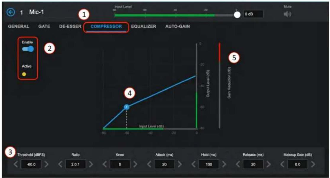
- A compressor is a dynamic setting that can automatically reduce peaks in volume and smooth out a radically changing signal. It is used differently depending on what instrument or signal is being tamed. Compressing reduces the peak levels by squashing the sound into more even levels, reducing channel clipping, while remaining loud. A good setting sounds natural and rich. The art of setting up a compressor correctly takes some practice. While learning, subtle changes are a good routine.
- Enable the Compressor and Active indicator.
- Settings: Threshold, Ratio, Knee, Attack Time, Hold Time, Release Time, Makeup Gain.
• Threshold: The signal level required to engage the Compressor.
• Ratio: The amount of reduction compared to signal when compressing.
- Knee: The smoothing curve at the Threshold.
- Attack Time: The amount of time to fully engage the Compressor after signal level increases beyond the threshold.
- Hold Time: The amount of time Compression is held after the signal level decreases below the threshold.
-
Release Time: The amount of time to fully disengage the Compressor after hold time has expired.
• Makeup Gain: This is a way to level up gain that is reduced by the Compression. -
Display of compression curve with dynamic Threshold, Knee, and Gain Reduction that can be adjusted by mouse, or touch and see-hear changes in real-time.
- Shows the activity of the Gain Reduction in real time to help adjust the required amount.

Atlas IED
1601 JACK MCKAY BLVD.
ENNIS, TEXAS 75119 U.S.A.
TELEPHONE: (800) 876-3333
SUPPORT@ATLASIED.COM
AtlasIED.com
Atmosphere
User Manual
Equalizer
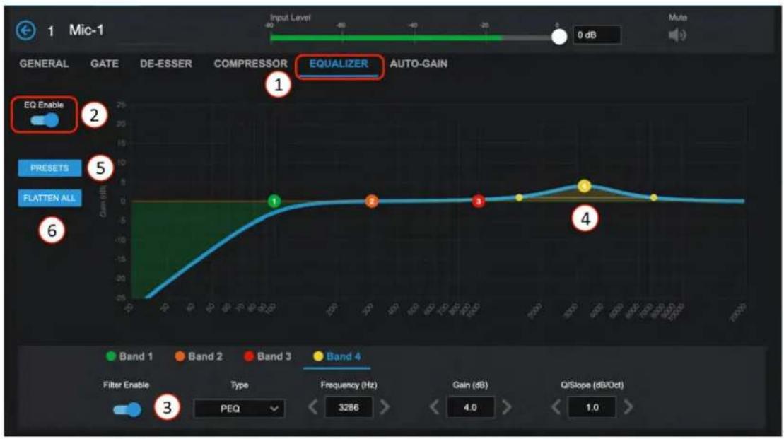
- Equalizers allow raising or lowering the level of individual frequencies or ranges (bands) of frequencies to improve the overall sound of a source signal. Narrow bands can also be set to remove problems, like feedback or an acoustically induced low end.
- EQ Enable/Bypass in real-time; Adjustable frequency and Q controls for each band.
- Enable/Disable Filter by band and chose filter type selections:
• Band 1 types include:
- PEQ
- Low Shelf
- High Shelf
- Notch
- High Pass Presets: BW6 HP, BW12 HP, BW24 HP
• Band 2 & 3 types include:
- PEQ
- Low Shelf
- High Shelf
- Notch
- Band 4 types include:
- PEQ
- Low Shelf
- High Shelf
- Notch
-
Low Pass Presets: BW6 LP, BW12 LP, BW24 LP
-
Dynamic fully adjustable bands on graphic display.
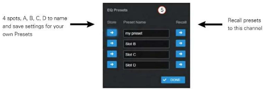
- Select Presets to open a pop-up with four memory spots for EQ settings, A-B-C-D; name and store your favorite EQ settings from one channel, then recall (copy) it to another channel.
- Flatten All – resets EQ filters to baseline 0dB from 20Hz to 20KHz.
Preset Popup Window
flowchart
graph LR
    A["4 spots, A, B, C, D to name and save settings for your own Presets"] --> B["EQ Presets"]
    B --> C["Store"]
    B --> D["Preset Name"]
    B --> E["Recall"]
    C --> F["my preset"]
    D --> G["Slot B"]
    E --> H["Slot C"]
    E --> I["Slot D"]
    I --> J["DONE"]
    J --> K["Recall presets to this channel"]

Atlas IED
1601 JACK MCKAY BLVD.
ENNIS, TEXAS 75119 U.S.A.
TELEPHONE: (800) 876-3333
SUPPORT@ATLASIED.COM
AtlasIED.com
Atmosphere
User Manual
Auto-Gain Control
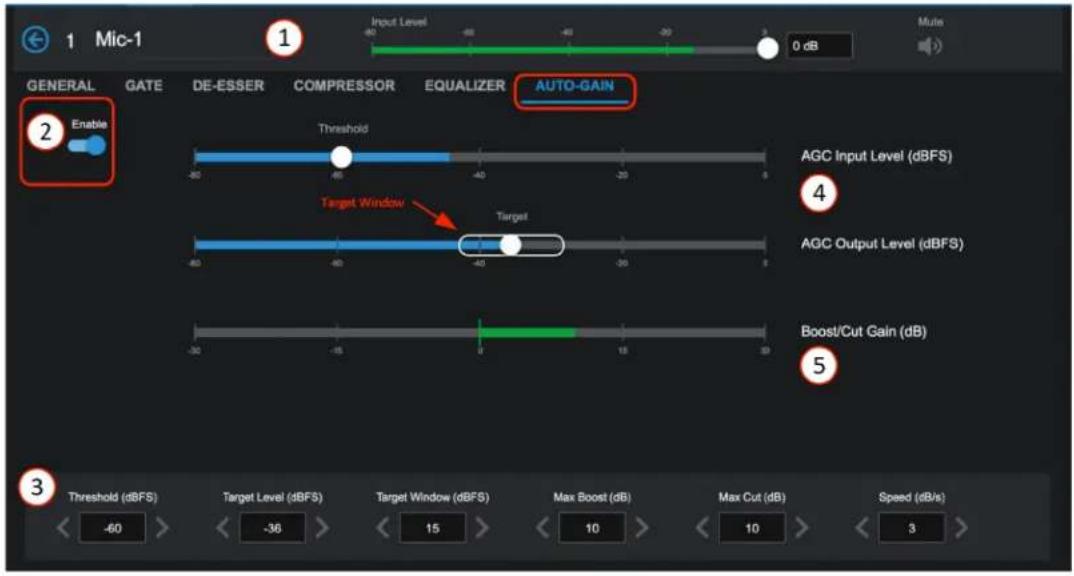
When stepping to a microphone, everyone speaks with a different level of voice projection; some almost whisper and some sound like they are shouting. Background music levels can be inconsistent between tracks. These are just a couple examples of issues the Auto-Gain Control (AGC) can help solve. Auto-Gain attempts to maintain a consistent output level regardless of variations in input level. This allows an integrator to set target input source levels for a room, letting the Auto-Gain maintain levels "in-target range" so adjusting controls is not necessary.
- The input channel remains accessible for adjustment while using setup pages.
- Enable-ON/OFF (bypass)
-
Dynamic settings: Threshold, Target Level, Target Window, Max Boost/ Cut, Speed.
-
Threshold: Auto-Gain will only be active when the input signal's RMS levels exceed the threshold setting.
• Target Level: This is the RMS level which Auto-Gain attempts to maintain. - Target Window: When AGC output level is within the Target Window, AGC does not modify the gains. This is a sort of hysteresis control which helps AGC avoid being over-active once the general target gain has been reached. 15 dB is a good general setting for speech or music. Reduce the window to keep output levels closer to the target. Increase the window if AGC is causing noticeable "pumping" gain movements during normal operation.
• Max Boost/ Cut: These dictate how much gain the algorithm can boost/ cut as it attempts to maintain the required output level.
• Speed: How fast Auto-Gain adjusts gains to maintain the requested output level.
Note: A higher "Speed" is likely to produce the best results for voice while a slower "Speed" setting is best for background music applications.
- AGC Input bar graph level with threshold setting and AGC Output level with target setting to manage settings range.
- Bar graph meter displays the applied boost/ cut gain (dB) to keep signal in range in real time.

Atlas IED
1601 JACK MCKAY BLVD.
ENNIS, TEXAS 75119 U.S.A.
TELEPHONE: (800) 876-3333
SUPPORT@ATLASIED.COM
AtlasIED.com
Atmosphere
User Manual
Audio Wall Plate Accessories
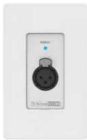
A-XLR
Balanced Mic/Line Input
natural_image
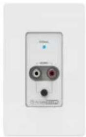
Close-up of a wall-mounted electrical outlet with a black plastic plug (no visible text or symbols)A-RCA
Stereo Summed dual RCA or 3.5mm TRS Input
natural_image
Front view of a white electronic device with two ports and a small black button (no visible text or symbols)A-BT
Bluetooth Input
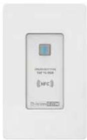
Audio Wall Plate Accessories that begin with an "A", denoting that they are audio inputs, include:
A-XLR, A-RCA, and A-BT. Note: Only one audio input accessory can be connected to each bus-port (AZM4 has Ports A & B; AZM8 has Ports A,B,C,D). Once the Audio Wall Plate is connected to the AZM bus-port, the input associated with the bus-port will activate and can be selected as an input source where general settings can be configured. The general settings DSP available will be the same as source inputs.
To add an Audio accessory, begin by opening the Accessory tab and connect the accessory to a port that does not have another Audio accessory. When an audio wall plate accessory is connected to one of the 4 ports (AZM8), the device will show up on the respective port and display the type. When it becomes active, the indicator displays a green check mark (#3). It will then appear on the input source selection list in the Add Source popup configuration page.
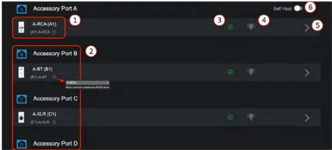
- The accessory input ports remain unpopulated until an accessory is present and detected on the bus-port.
- Once connected, like Port A, B & C, the port will light up and identify the accessory type. The top default name can be edited, the lower ID with type and port number, will not change. This is the accessory part number and not the same as the Input Source Name. Clicking on the "?" will show a description of the accessory type for reference.
- After the accessory is recognized, a green check appears indicating it is updated and ready to use. Note: It can take up to 30 seconds for an audio wall plate to be detected and start streaming audio.
- Click on this "Locate" icon to flash the LED on the accessory to aid in finding its physical location.
- The “>” icon is the link to the accessory page. The accessory page allows editing of the name, shows the location of the accessory on the bus port, and in some cases, basic settings specific to the type of Audio wall plate. Go to Source General Settings to configure the audio settings.
- After installing a system, switch on "Self-Heal" and the system will automatically retain the settings in the event a wall controller accessory requires replacement on a port. Simply remove the faulty unit and plug in the new; the system will recognize it and update the settings exactly as it was before. No additional programming will be required.

Atlas IED
1601 JACK MCKAY BLVD.
ENNIS, TEXAS 75119 U.S.A.
TELEPHONE: (800) 876-3333
SUPPORT@ATLASIED.COM
AtlasIED.com
Atmosphere
User Manual
Audio Wall Plates A-XLR Settings on Accessory Page
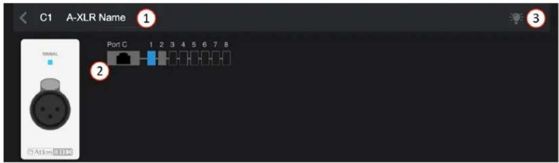
- The accessory settings page displays the editable accessory name. The default is type and port with location on bus.
- Shows input graphic of accessory type, A-XLR, and port "C" with bus order location "1" (C1).
- Click on this locate icon to flash the LED on the accessory to aid in finding its physical location.
Add Source for A-XLR on Input Source Page
- Go to Source page and select Add Source to open the configuration popup.
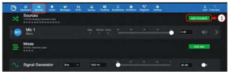
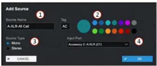
- Each input can be named here and will be added to the input source selection list system wide.
- A letter or numeric tag and color can be selected to enhance visualization and help identify source types.
- Inputs Sources can be Mono or Stereo, select here prior to assigning the input port.
- Select the input port or, if stereo, input ports (left/right) from the drop-down list of available inputs and select OK to add the Source to the Sources List.
General Settings for A-XLR Source Page
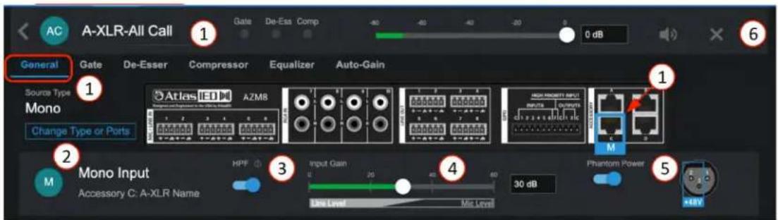
- The General Settings page displays the editable Source Name, identifies physical location of input for wiring, and navigation tabs for DSP settings: Gate, De-Esser, Compressor, Equalizer, and Auto-Gain. (same as DSP on Mic/Line page above).
- Shows input type and port name, select "Change Type or Ports" to re-configure if desired.
- Pre-set High Pass Filter Enable – a separate EQ filter placed before the Gate, Compressor, and Equalizer, allowing all bands of the equalizer to be used for other requirements.
- 0dB to +60 dB of preamp gain available to fine tune input sensitivity for Mic or Line sources.
- Phantom Power Enable.
- Delete source "X" and Mute Source along with source (input) level fader.

Atlas IED.
1601 JACK MCKAY BLVD.
ENNIS, TEXAS 75119 U.S.A.
TELEPHONE: (800) 876-3333
SUPPORT@ATLASIED.COM
AtlasIED.com
Atmosphere
User Manual
Audio Wall Plates A-RCA Settings on Accessory Page
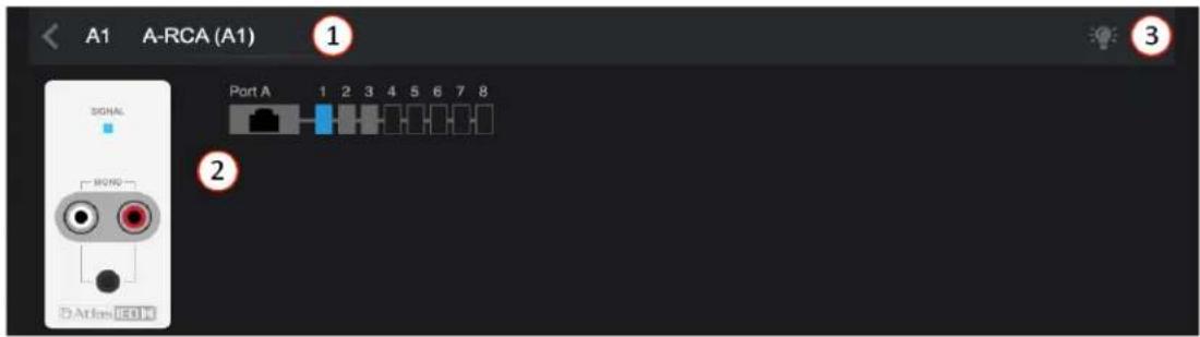
- The accessory settings page displays the editable accessory name. The default is type and port with location on bus.
- Shows input graphic of accessory type, A-RCA, and port "A" with bus order location "1" (A1).
- Click on this locate icon to flash the LED on the accessory to aid in finding its physical location.
Note: Follow the instructions above to "Add Source" to Input Source List for all audio accessories.
General Settings for A-RCA on Source Page
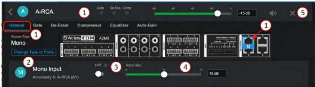
- The General Settings page displays the editable Source Name, identifies physical location of input for wiring, and navigation tabs for DSP settings: Gate, De-Esser, Compressor, Equalizer, and Auto-Gain. (same as DSP on Mic/Line page above).
- Shows input type and port name, select "Change Type or Ports" to re-configure if desired.
- Pre-set High Pass Filter Enable – a separate EQ filter placed before the Gate, Compressor, and Equalizer, allowing all bands of the equalizer to be used for other requirements.
- 0 - 30dB of gain available to fine tune input sensitivity.
- Delete source "X" and Mute Source along with source (input) level fader.
Atmosphere
User Manual
Audio Wall Plates A-BT Settings on Accessory Page
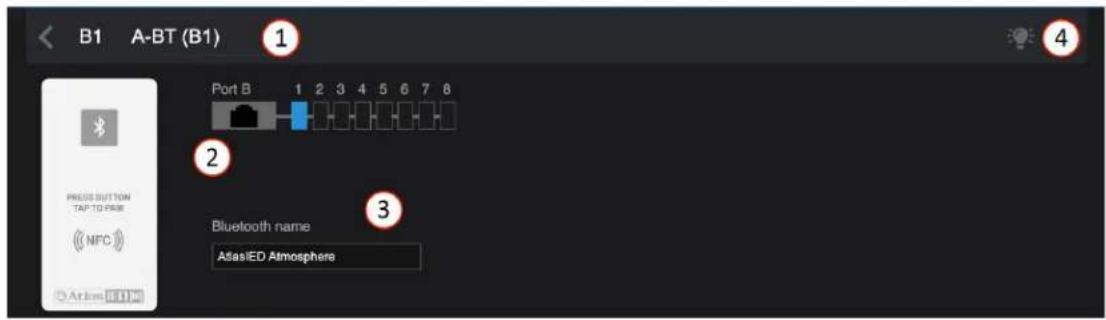
- The accessory settings page displays the editable accessory name. The default is type and port with location on bus.
- Shows input graphic of accessory type, A-BT, and port "B" with bus order location "1" (B1).
- Bluetooth® name - this is the editable name that will show up in your Bluetooth® mobile device connection list.
- Click on this light icon to flash the LED on the accessory to aid in finding its physical location.
General Settings for A-BT on Source Page
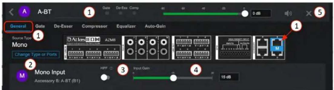
- The General Settings page displays the editable Source Name, identifies physical location of input for wiring, and navigation tabs for DSP settings: Gate, De-Esser, Compressor, Equalizer, and Auto-Gain. (same as DSP on Mic/Line page above).
- Shows input type and port name, select "Change Type or Ports" to re-configure if desired.
- Pre-set High Pass Filter Enable – a separate EQ filter placed before the Gate, Compressor, and Equalizer, allowing all bands of the equalizer to be used for other requirements.
- 0 - 30dB of gain available to fine tune input sensitivity.
- Delete source "X" and Mute Source along with source (input) level fader.
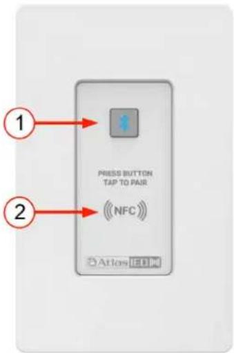
How to pair with the A-BT Wall Plate
- Using NFC – Press the pairing button (1) and it will light blue.
a. With the mobile device Bluetooth® turned ON, tap your mobile device to the NFC symbol (2) on the A-BT.
b. A-BT indicator (#1) will turn green after connecting successfully.
- Manually - Press the pairing button (1) and it will light blue.
a. Look in your mobile device Bluetooth list and select the Bluetooth ^3 "Name" you entered on the General Settings page.
b. When a connection is established, the LED will turn from green.
c. Pressing the pairing button (1) when connected, will disconnect the pairing.
Note: It will NOT auto-pair again, you must press the pairing button (1) or, tap NFC (2) again to initiate a connection.

Atlas IED
1601 JACK MCKAY BLVD.
ENNIS, TEXAS 75119 U.S.A.
TELEPHONE: (800) 876-3333
SUPPORT@ATLASIED.COM
AtlasIED.com
Atmosphere
User Manual
Mixes
- The "Mixes" source provides four separate Mix Channels each allowing a selection of any source inputs to be combined into a sub-mix channel with a single audio master fader adjustment.
- Select ADD MIX to add and configure a Mix Channel.

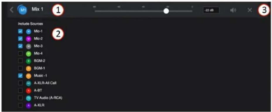
- Each Mix can be named here and will be available to any zone by selecting from the zone inputs source lists.
- Select input sources for Mix 1 channel.
- The "X" deletes the mix and is only available in mix settings. Input level adjust – move fader or enter in dB level desired in window. When signal is present, fader animates as a pre-fader peak meter and shows: Green = signal activity, Red = clipping. Note: Pay close attention to gain structure when combining several sources.
Input Mix Page
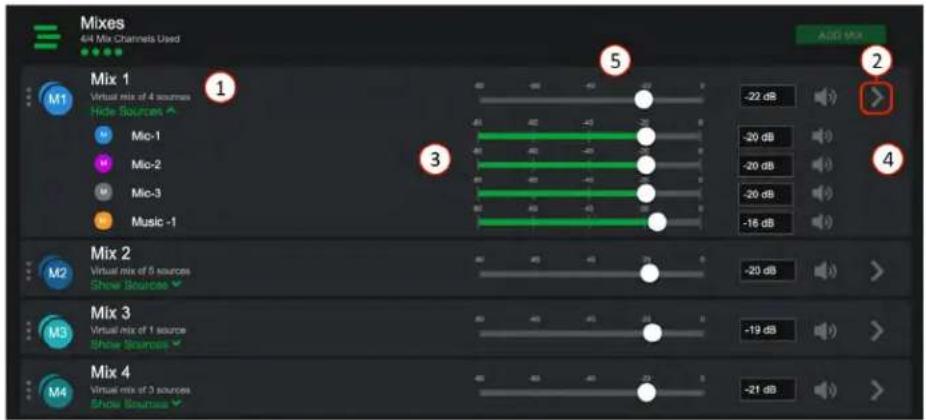
- Each Mix channel has a "Show Sources" options. When selected it drops down each source and fader for mixing, when done, "Hide Sources" retracts sources and only displays the master mix fader.
- This ">" icon opens the settings page to select or un-select sources to include in group mix.
- Mix each level to desired group mix.
- Mute - select to mute input channel.
- Set level of master mix (Mix 1) to output (each of the 4 Mix channels appear in the source list in zone outputs).

Atlas IED
1601 JACK MCKAY BLVD.
ENNIS, TEXAS 75119 U.S.A.
TELEPHONE: (800) 876-3333
SUPPORT@ATLASIED.COM
AtlasIED.com
Atmosphere
User Manual
Signal Generator Input

The Signal Generator Input provides a way to test, setup, and troubleshoot zones with a consistent audio source. A sine wave with frequency setting is a tone and useful in calibration throughout the system. White noise is a random signal containing equal energy per frequency, giving it a constant power spectral density. Pink noise has equal energy per octave. Octave bands are how humans hear so it is useful for setting up music levels in zones.
- Signal Type – select sine wave, white noise, pink noise
- Enter the frequency for sine waves in Hz
- Set input level
- Enable switch
*The Signal Generator can be assigned as a source on zone outputs only.
Zones
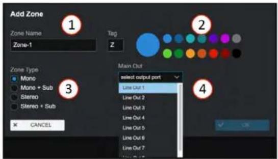
The Zones page is where you add and configure the outputs. Just like sources, you will select ADD ZONE to open the configuration popup and select configuration settings. A zone can be more than one output when configured as Mono + Sub, Stereo, or Stereo + Sub.

- Enter Zone name.
- Select color and edit tag if desired.
- Select type prior to selecting outputs.
- Select available output or outputs.

- Click on this icon to move this Zone up or down in the zone list.
- Each output zone name and type is displayed here, rename in settings.
- Select Source Input – select from the available input source drop down list.
- This is the input priority signal activity indicator.
- Output level adjust – move fader or enter dB desired output level in window. When signal is present, fader animates as a peak meter and shows: Blue-signal activity, Red-clipping.
- Mute - select to mute output channel.
- Limiter Activity indicator, Yellow - limiting, Gray - no limiting.
- Link to settings navigates to the following pages:

Atlas IED
1601 JACK MCKAY BLVD.
ENNIS, TEXAS 75119 U.S.A.
TELEPHONE: (800) 876-3333
SUPPORT@ATLASIED.COM
AtlasIED.com
Atmosphere
User Manual
Zone - Mono - General Settings Page
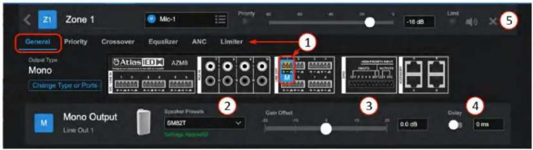
- The General Settings page shows the port to wire connection to, and DSP settings pages for Priority, Crossover, Equalizer, Ambient Noise Compensation (ANC) Control, and Limiter.
- Speaker Preset – select from a list of AtlasLED speakers and load output preset EQ tuning for that specific speaker.
- Gain Offset adjust with -20dB to +20dB.
- Delay adjustment from 0 to 100ms with enable/bypass- typically used to sync sound when speakers are located far away and at different distances from target audience.
- The "X" icon will delete the zone.
Zone - Stereo + Sub - General Settings Page
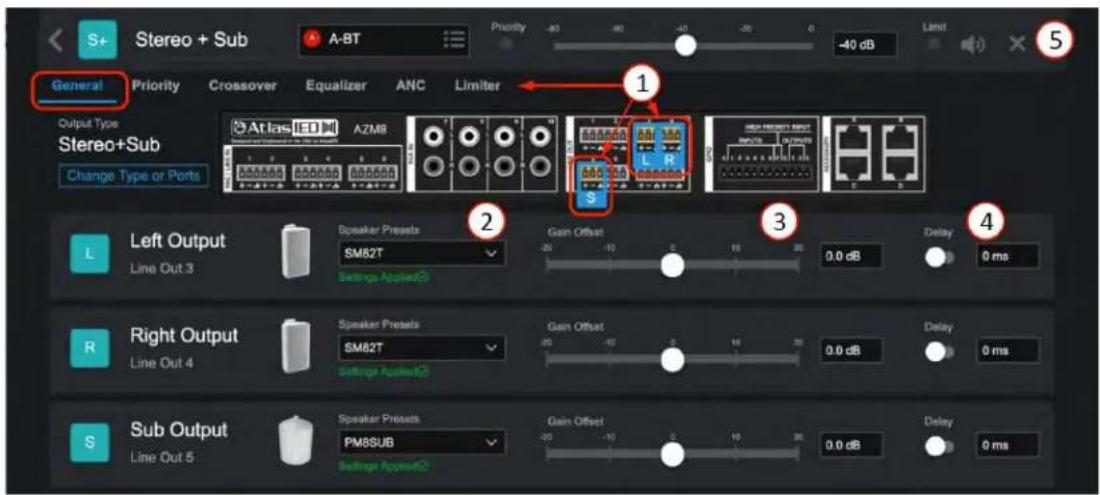
- When a Stereo or Stereo + Sub Type is selected, the General Settings page shows the ports to wire connection to and DSP settings pages for Priority, Crossover, Equalizer, Ambient Noise Compensation (ANC) Control, and Limiter. Each DSP page, where appropriate, adjusts the Left and Right channel as a single pair referred to as "Main" and the "Sub" is displayed for adjustment separately. A mono source will be split across the zone speakers. Stereo sources, with a Left and Right source, will remain stereo.
- Speaker Preset – select from a list of AtlasIED speakers and load output preset EQ tuning for that specific speaker.
- Gain Offset = -20dB to + 20dB, allows balancing the levels relative to the primary zone level out.
- Delay adjustment from 0 to 500ms with enable/bypass- typically used to sync sound when speakers are located far away and at different distances from target audience.
- The "X" icon will delete the zone.

Atlas IED
1601 JACK MCKAY BLVD.
ENNIS, TEXAS 75119 U.S.A.
TELEPHONE: (800) 876-3333
SUPPORT@ATLASIED.COM
AtlasIED.com
Atmosphere
User Manual
Zone - Priority
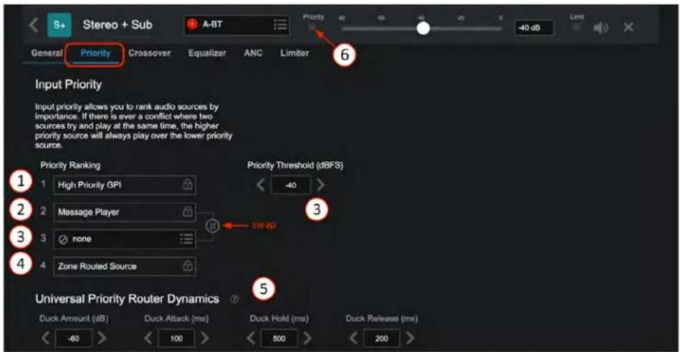
The Input Priority page allows you to rank audio sources for each zone by importance to mitigate a conflict where two sources try to play at the same time. The higher priority source will always play over the lower priority source.
- The High Priority GPI is permanently set to the highest priority.
- Message Player—select the "swap" button to arrange whether Msg Player or RMS Ducker has higher priority after GPI HP input. The top selection is highest priority.
- Priority Input Source Selection and Priority Threshold – when the selected priority input source's RMS levels exceed the priority threshold, the priority source will duck the normal input source channels.
- Zone routed sources are permanently set to lowest priority.
- The ducker dynamic settings are common for all channels and are adjustable here and also accessible via Settings > Device Settings.
- Priority input status indicator- will light yellow when the priority source is actively ducking the main source. It will be grey when inactive.
Zone - Crossover
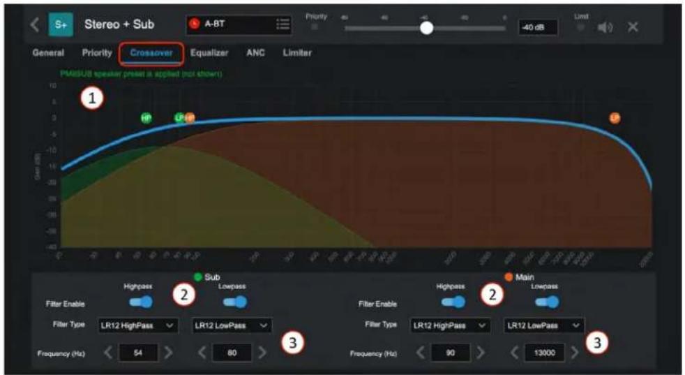
- Th e Crossover provides a HighPass and LowPass adjustable filter for Main (Mono and Stereo source) and when Sub is added, an additional HighPass and Lowpass just for the subwoofer. Dynamically move graphic or select and enter settings.
- Enable-Bypass for each filter, helps to audition the changes.
- Chose HP and LP presets by type (Butterworth or Linkwitz Riley) and Slope/Octave: BW6dB, BW12dB, BW18dB, BW24dB, LR12dB, LR24dB

Atlas IED
1601 JACK MCKAY BLVD.
ENNIS, TEXAS 75119 U.S.A.
TELEPHONE: (800) 876-3333
SUPPORT@ATLASIED.COM
AtlasIED.com
Atmosphere
User Manual
Zone - Equalizer
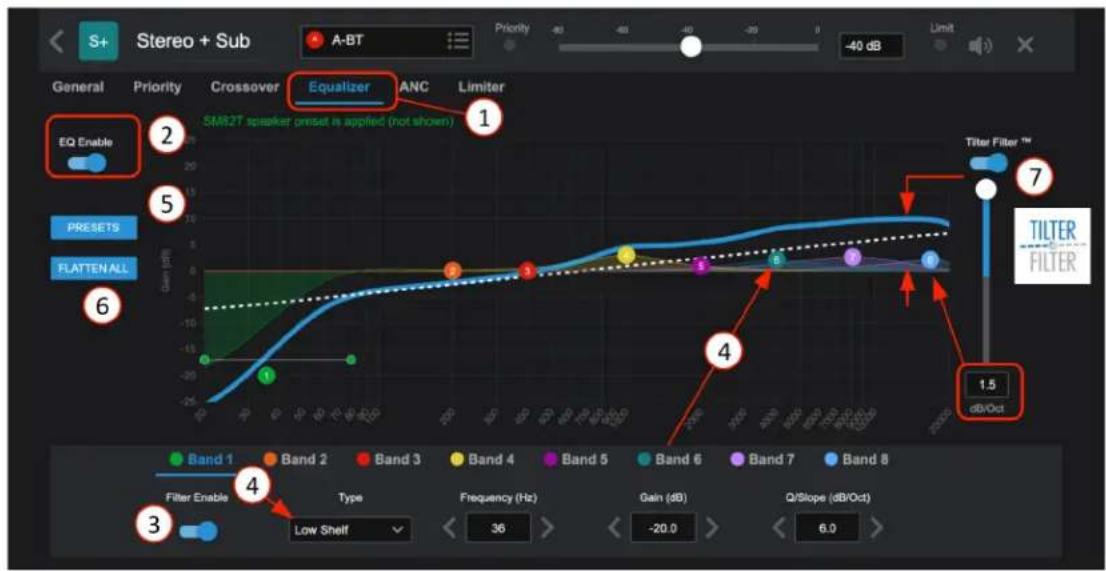
- Equalizers allow raising or lowering the level of frequencies or ranges (bands) of frequencies to improve the overall sound of a source signal. Narrow bands can also be set to remove problems, like feedback or an acoustically induced low end.
- EO Enable/Bypass in real-time.
- Enable/Bypass filter by band.
- Choose each band filter type. Selections include: PEQ, Low Shelf, High Shelf, and Notch. Then, adjust Frequency, Gain, and Q/Slope.
- Note: Select and set location and Q for bands 1-8 can also be done dynamically on the graphic display.
- Select Presets to open a pop-up with four memory spots for EQ settings, A-B-C-D; name and store your favorite EQ settings from one channel, then recall (copy) it to another channel.
- Flatten All - resets EQ filters to baseline 0dB from 20Hz to 20KHz
- Tilter Filter- allows a simple full spectrum "tilt" to adjust the overall brightness of the signal by "tilting" the entire 20Hz to 20KHz band up/down.
Atmosphere
User Manual
Zone - Ambient Noise Compensation - ANC
Ambient Noise Compensation works in conjunction with the X-ANS (Ambient Noise Sensor Accessory; see X-ANS install placement rules). The X-ANS is installed in the zone where the noise levels vary depending on activity and where the audio level needs to be managed so it can always be heard. For example, this can be used for keeping an announcement clear and intelligible above the changing ambient noise in the zone. This function allows ambient noise to control zone output level settings based on the ambient noise sensor's SPL when placed in the zone to be controlled. The sensor's dedicated filter helps it determine the noise to react to, and what to ignore, essentially "compensating" for the difference between the ambient noise and the audio levels; for example, an arcade area when full of people playing games vs when no one is playing games. The ambient noise sensor provides only data (not voice files) back to the AZM and ANC feature so it cannot be "listened" to and doesn't carry any privacy concerns. The settings page shows SPL readings to help establish range and levels. It also has an Auto mode where the system learns the ideal compensation gain settings from user adjustments to the zone's output levels. The Auto mode improves the all-around audio in a changing room.
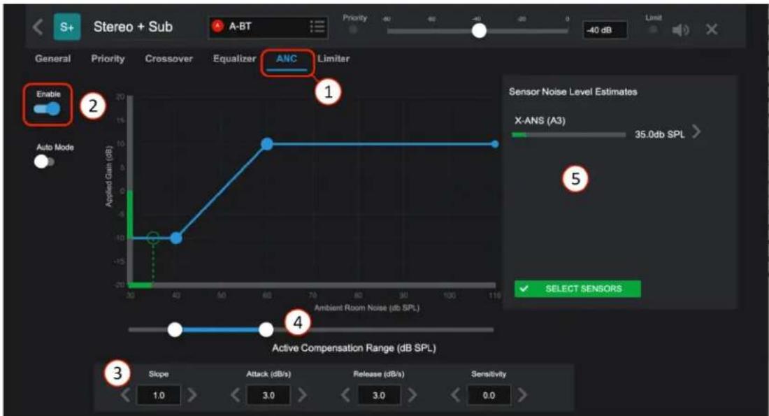
- Select to open the Ambient Noise Compensation settings page.
- Enable On/bypass
-
ANC Parameters
-
Slope – How much dB gain to apply per dB change in noise level
- Attack – Gain increase rate in dB/second
- Release – Gain decrease rate in dB/second
- Sensitivity – Default 0. Set high enough to detect changes in ambient noise, and low enough to avoid false detections of system audio as ambient noise. If ANC cannot detect ambient noise while avoiding false noise detections, the ANS sensor should be moved closer to the noise source and farther from the speakers.
- ANC will actively modify gains when ambient noise lies within this range.
-
Panel for assigning and viewing X-ANS sensors. When Ambient Noise Sensors are connected, this panel displays the Estimated Noise SPL of each assigned X-ANS sensor.
-
Note: You may not see SPL information immediately after assigning an X-ANS sensor. The sensor takes 1-2 minutes to boot after plugging in, and ANC takes 10-30 seconds after that to train its adaptive filter before delivering SPL estimates.
- Note: In a large Zone, multiple Ambient Noise Sensors can be assigned to a single zone. When multiple sensors are used, the SPL results are averaged to avoid over-reaction to local noise hotspots. (See X-ANS on Accessory Settings Page for dynamic levels)

Atlas IED
1601 JACK MCKAY BLVD.
ENNIS, TEXAS 75119 U.S.A.
TELEPHONE: (800) 876-3333
SUPPORT@ATLASIED.COM
AtlasIED.com
Atmosphere
User Manual
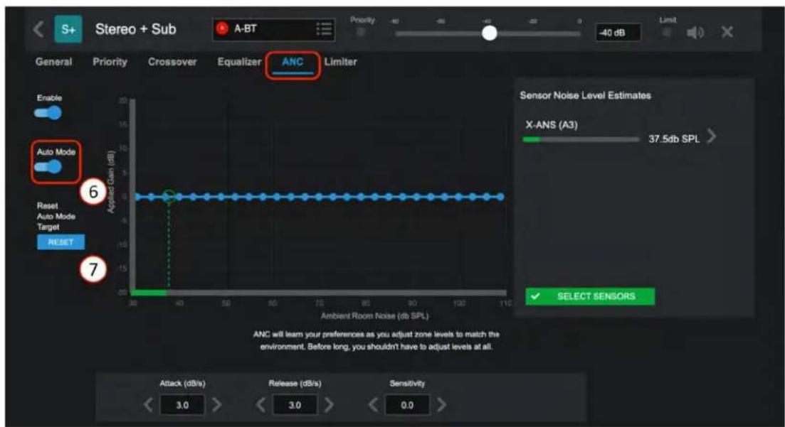
- Enables Auto Mode. Like a smart thermostat, the system will learn the ideal noise-compensating gains to apply as the end-user adjusts zone gains while the ANS sensor is assigned to the zone. Because of this, Auto Mode should be used in a system where the end-user will have control over zone gains via Main UI, Virtual Wall Controller, or C-V / C-ZSV accessories. After a few gain adjustments at the various ambient noise levels experienced in the zone, the system will be custom calibrated to react to the noise in a manner consistent with the end-user's specific preferences.
- Reset Auto Mode Target – This control resets the Auto Mode system to allow a fresh start for re-training the algorithm.
Note: It is recommended to use Auto-Gain on the source audio feeding the ANC algorithm. This facilitates a more consistent output signal level to help ensure that customers can hear the source audio in the affected zone.
Ambient Noise Sensor X-ANS (with included Decora trim plate)
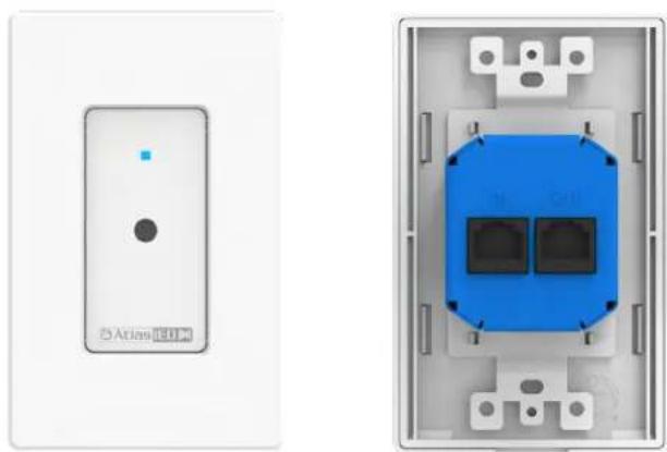
natural_image
Two electronic wall-mounted devices: one with a white panel and one with a blue internal component (no visible text or symbols)Atmosphere
User Manual
Ambient Noise Sensor Placement
Correct placement of the X-ANS Ambient Noise Sensor is a critical, aspect of a good system installation. The X-ANS provides real-time noise level measurements to the Atmosphere's system that, in turn, allows the system to continuously adjust the zone output level to maintain an intelligible announcement above the current noise level in the zone. No system calibration is required, because the Ambient Noise Compensation system uses advanced adaptive filters to differentiate between system audio and ambient noise.
The sensors must be placed in a location within each zone to allow for optimal detection of the ambient noise level while maintaining the ability to distinguish between the noise and the PA system. This location is dependent on the speaker placement and the acoustical characteristics of the space where the sensor is located. Due to this complexity, there is no single rule to define exact sensor placement. However, there are five basic rules that should always be considered when placing the X-ANS Ambient Noise Sensor.
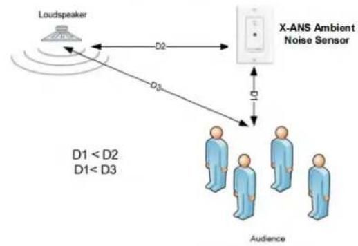
RULE 1: The distance between the sensor and the audience should be less than the distance between the sensor and the loudspeaker.
RULE 1:
The distance between the sensor and the audience should be less than the distance between the sensor and the loudspeaker
flowchart
graph TD
    A["Loudspeaker"] -->|D2| B["X-ANS Ambient Noise Sensor"]
    B -->|D3| C["Audience"]
    style A fill:#f9f,stroke:#333
    style B fill:#ccf,stroke:#333
    style C fill:#cfc,stroke:#333
In most installations, the sensor will be placed in the ceiling located in the zone that it will control. The ANC system uses an adaptive filter to "learn" what the audio system contributes to the overall zone ambient noise level and then filter that portion out of the calculation when adjusting the level. When sensors are placed too close to the loudspeaker, the direct sound from the loudspeaker effectively masks the ambient noise from the sensor. While the algorithm should prevent the system from turning the level up based on the speaker output, the level will not properly track in real time as levels change since the sensor cannot properly detect the current level of ambient noise. Placing the sensor in a location that allows it to be closer to the source of the noise than the adjacent speakers will prevent the masking effect from impairing the performance of the system.
Atmosphere
User Manual
RULE 2: The sensor must be placed far enough away from the audience as not to pick up on individual conversations.
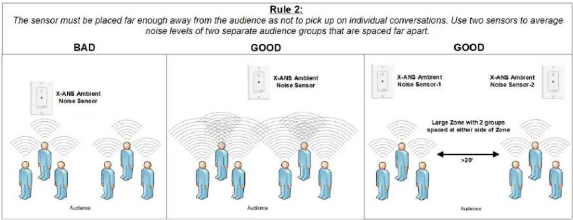
Placing the sensor too close to the source of ambient noise will cause the system to adjust primarily based on noise in one small location. In most systems, the ambient noise that is being detected is due to crowds of people moving into and out of the zone. If a sensor is placed too close to the crowd, it will pick up on individual conversations and the system will adjust based only on the isolated conversation. The sensor should be located where it will pick up the cumulative level of all conversations in the space. Multiple X-ANS sensors can be assigned to a single zone to help prevent over-reaction to a noise source in one specific part of the zone.
Note: The X-ANS sensor is not a microphone and does not pick up audio and transmit it back to the system. It converts levels to data and passes this level information back to the system. Therefore, there are no concerns that the system can violate any privacy.
RULE 3: Do not place a sensor at the edge of a zone where it will pick up sound from adjacent zones.
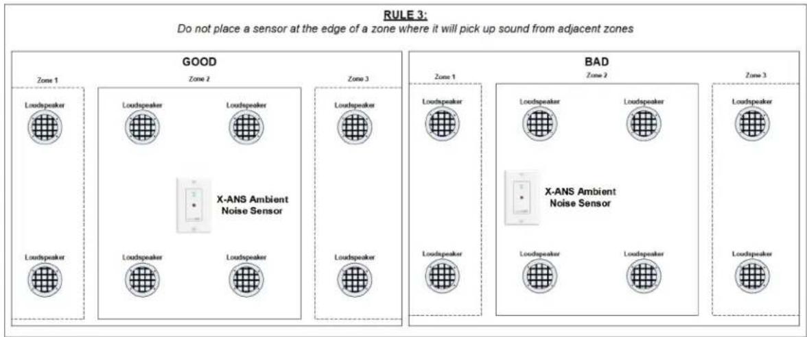
Placing the sensor too close to the edge of a zone can result in the level of the zone being adjusted based on program audio generated in the adjacent zone. Since the ANC algorithm only analyzes audio from the zone where the sensor resides, audio created by the PA system in an adjacent zone could cause the level of the parent zone to change. Placing the sensor in a centralized location within the zone will minimize the impact of audio from adjacent zones.

Atlas IED
1601 JACK MCKAY BLVD.
ENNIS, TEXAS 75119 U.S.A.
TELEPHONE: (800) 876-3333
SUPPORT@ATLASIED.COM
AtlasIED.com
Atmosphere
User Manual
RULE 4: The sensor should be placed towards the middle of the zone with nearly equal distance between the sensor and immediately adjacent loudspeakers.
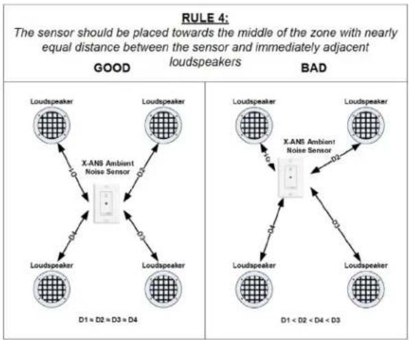
The reason behind this rule is to prevent similar issues encountered when considering Rule 1. If a sensor is located too close to any one speaker, the sound from that speaker could easily mask the ambient noise level from the sensor while an announcement is in progress. Since one sensor is usually placed in a zone with many loudspeakers, it is best to place the sensor where it is nearly equidistant from the immediately adjacent loudspeakers.
RULE 5: In spaces with high ceilings, place the sensor along a side wall at a location 6 to 12 feet above the listener.
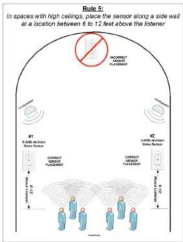
High ceiling spaces present a unique set of problems. In certain spaces, the ambient level near the top of the high ceiling does not vary significantly enough to match the noise changes near the floor. In this type of space, a sensor located in the high ceiling may lose its effectiveness. This problem is compounded when multiple zones are included in the same high-ceiling area. The ambient level is a culmination of the noise from all zones in the space. Therefore, it is usually best to place the sensors on a side wall or support column. This allows the sensor to be placed closer to the noise source and allows adherence to the previously mentioned rules. With this mounting location, adherence to Rule 2 is now more difficult. In order to provide proper level detection, the sensor should be located between 6 and 12 feet above the head of the listener. This would place the sensor between approximately 12 and 18 feet above the floor. This allows the sensor to be placed at a point that will reduce the effects of noise sources that are located close to the sensor location. As in Rule 2, multiple sensors may also be used to help avoid overreaction to localized noise sources.

Atlas IED
1601 JACK MCKAY BLVD.
ENNIS, TEXAS 75119 U.S.A.
TELEPHONE: (800) 876-3333
SUPPORT@ATLASIED.COM
AtlasIED.com
Atmosphere
User Manual
Limiter
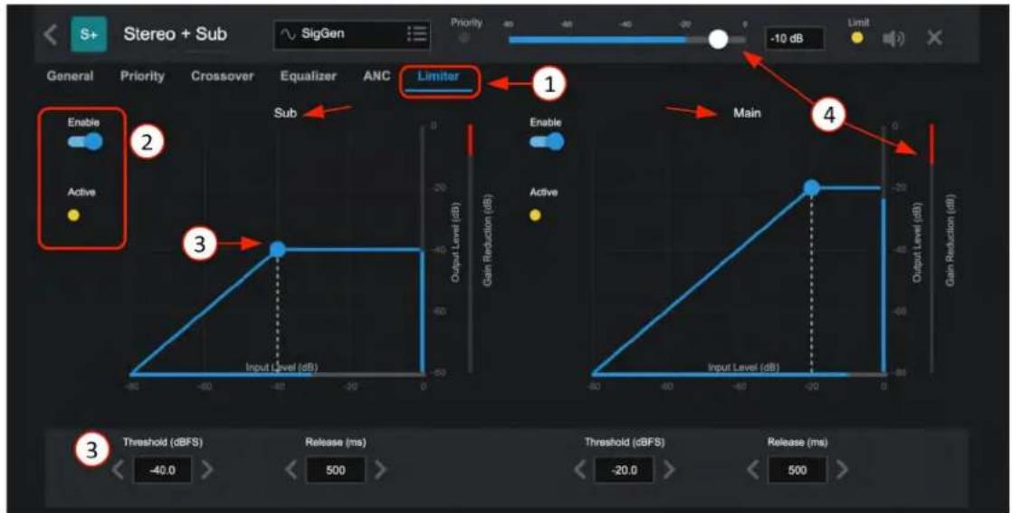
- The Output Limiter is used primarily for taming transient peaks to keep the output signal strength below a specified level. This can help prevent damage to loudspeakers in the event of unintended loud signals like the drop of a microphone. When Zones are Mono or Stereo, only the Main Limiter is displayed. When a Sub is added, a separate limiter is available to tame the energy of the Sub so it doesn't affect the Main.
- Enable On/bypass and Active indicator.
-
Protection for the output can be adjusted with the following parameters:
-
Threshold – level where the limiter starts limiting
- Knee – controls the abruptness of the limiting as audio nears the threshold
- Attack Time – how fast the limiter engages
- Hold Time – how long it stays in limit mode after peaks drop below threshold
-
Release Time – how fast the limiter stops after hold time.
-
This shows a signal Main output being limited to -20dB, and the input signal is being reduced (Gain Reduction). If the gain reduction is significant, reducing the source level will reduce the amount of Gain Reduction needed, without changing the output level at the zone. These settings can help smooth out the limiter's effect, so the audio sounds natural while still protecting the speakers in the system. Too much limiter will destroy the dynamic range of music.
Atmosphere
User Manual
Zone-Groups Overview
The Groups feature, also referred to as Room Combine, allows zones to be assigned to a group and then combined and uncombined by the following actions: Manually (using the "Combine" toggle), GPI, Scheduled event in a scene, or Recall as a routine. The Group also allows a source to be assigned to overtake the individual zone sources when the zones are combined.
The Zones page is where you add and configure the groups. Select ADD GROUP to open the configuration popup.

- Enter Group name. In this case, we want to combine Rm 1 + 2
- Select color and edit tag if desired.
- Select an input source for the group when combined if desired.
Note: This is optional and not required to proceed creating a group.
- Select zones to include in group.
- There are optional settings for un-combine:
a. Revert = Group source selected and level control "reverts" back to where they were set prior to combining.
b. Release = Group source selected, and level control stays where they are set for each zone in group after un-combining but are free to move separately.
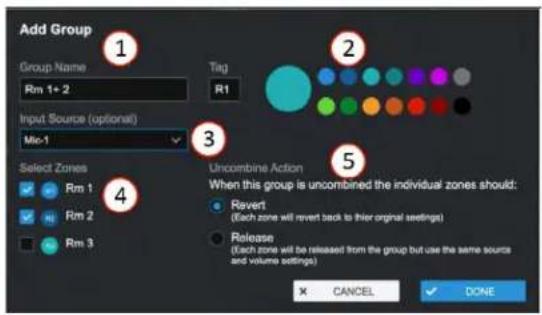
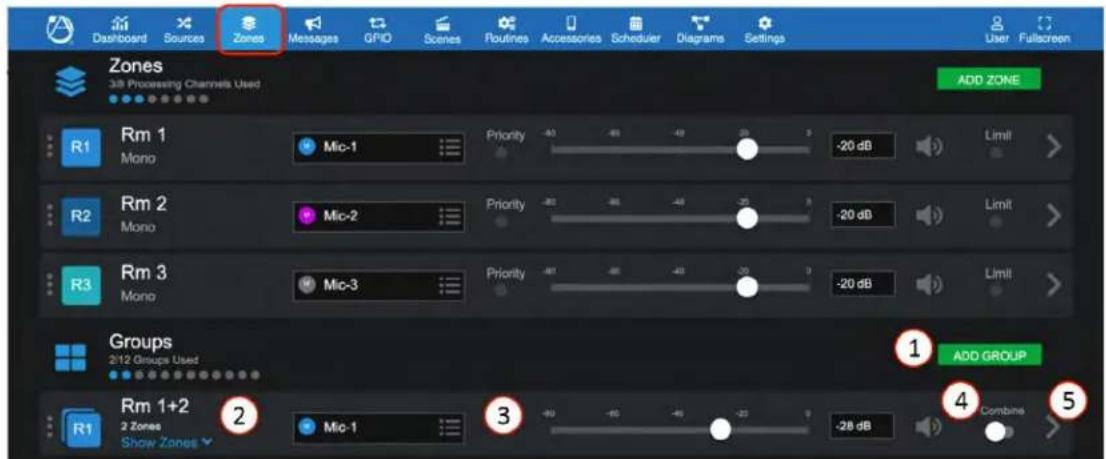
After the Group has been added, it appears in the Group List. Up to 12 groups can be configured.
- Click on ADD GROUP to add another group. Further down, you will see we added a group to combine Rm 1+2+3.
- Group name and number of zones included, click "Show Zones" dropdown to adjust zone offset levels or mute any zone.
- Select or change the group source input from the input source drop down list. When the group is active, this source will overtake all of the grouped zone's sources. The group level will also overtake the zone's level setting and make them follow the group level fader. Zone levels will follow the group offsets when in combined state.
- Mute - select to mute group channel.
- ">” icon links to settings page allows changing the zone selections, un-combine action, and delete group.

Atlas IED
1601 JACK MCKAY BLVD.
ENNIS, TEXAS 75119 U.S.A.
TELEPHONE: (800) 876-3333
SUPPORT@ATLASIED.COM
AtlasIED.com
Atmosphere
User Manual
Group Combine (Room Combine) - Active Active
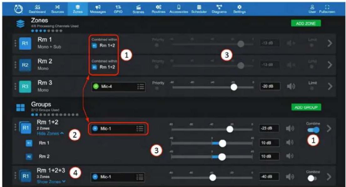
- When the group "Combine" is activated, the zones in the group will show "Combined within" group name (Rm 1+2) and zone levels will be grayed-out. The zone level is now determined by the group primary fader + zone offset fader.
- The active source for the entire group is Mic-1. Select "Show Zones" to adjust settings for each zone and "Hide Zones" to close the dropdown group settings.
- For each zone level set -40dB to +40dB offset level referenced to the primary group level if needed. When combined, the offsets will engage, moving the primary level will also move the zones retaining the offset mix. (Example above: each Rm set +10dB offset to -23dB primary; when combined, -23dB + 10dB = -13dB.)
- In this example, we've added an additional group to combine all three rooms. If Rm 1+2 is active when combine is activated for Rm 1+2+3, it will automatically de-activate Rm 1+2 and activate Rm 1+2+3, along with Mic 1 as group selected source.
Note: When activating a group, any existing active group with overlapping sources will un-combine and allow the new group action to take priority. i.e. the last action takes priority.
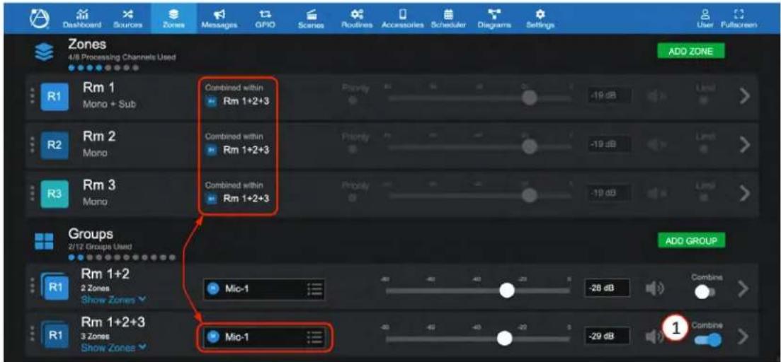

Atlas IED
1601 JACK MCKAY BLVD.
ENNIS, TEXAS 75119 U.S.A.
TELEPHONE: (800) 876-3333
SUPPORT@ATLASIED.COM
AtlasIED.com
Atmosphere
User Manual
Message Player Overview
The message player feature allows uploading and configuring audio files to the AZM messages storage library where they can then be selected and used by the system to play a message, tone, bell, or chime, as a stand-alone function or as part of system events, schedules, or triggered third party device functions.
Messages
Audio files, once uploaded, can then be configured and recalled as a Message Event in the following ways:
- As a Routine. (see Routines page to "Select" and/or "Include" message settings)
- Scheduled on the calendar. (See Scheduler "+ ADD EVENT" page)
- Selected from the front panel display.
- Selected to play by a ZSV accessory wall controller.
- Selected to play by a virtual wall controller. (See Accessories Tab "Virtual Wall Controller/ Messages" page to select)
- Triggered by one of the six GPI's or included as an Action Setting in the High Priority GPI. (See Settings "Tab GPIO Inputs" or "High Priority Input" settings)
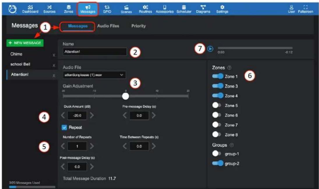
- Select the Message tab and "+ NEW MESSAGE" to create a new message settings profile or select an existing audio file to configure or modify its profile. Note: The same audio file can have multiple settings profiles saved as different names.
- Enter Message name
- Select the Audio File for this Message and adjust Gain.
- Pre-message Delay – sets the time prior to message playing after triggered, in seconds. "Duck Amount" affects existing zone sources while Message is active.
- Other Message settings: Repeat – select box, set number of repeats, Time Between Repeats (in seconds), and Post-message Delay (in seconds) (this is the wait time before reverting back to prior to message event or next in line priority event starts).
- Include zones and groups in the action when activated.
- Preview the message in the selected zones to check settings and that the message sounds acceptable.

Atlas IED
1601 JACK MCKAY BLVD.
ENNIS, TEXAS 75119 U.S.A.
TELEPHONE: (800) 876-3333
SUPPORT@ATLASIED.COM
AtlasIED.com
Atmosphere
User Manual
Audio Files
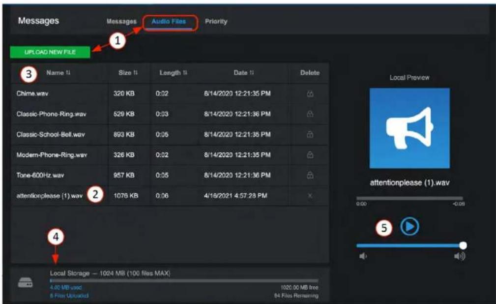
- Click on the Messages Toolbar to open the Messages page. Select Audio Files and Upload New File. Upload the .wav file from a computer.
- Audio Files must be: PCM-WAV (.wav - mono or stereo), 48kHz, any bit rate, 15 minutes maximum in length.
- The files can be sorted by Name, Size, Length, Date uploaded, or Deleted from the library.
- At the bottom, a local storage gauge shows amount of the available 1024 MB of local storage used.
- The Local Preview player allows a selected message from the library to be previewed. The audio will play on the default audio adapter on your device (computer/tablet).
Priority
Message priority allows you to assign the level of importance of your message list. This is most important when two conflicting messages are triggered during the same time. A message with a lower priority cannot interrupt a message with a higher priority, but a message with a higher priority will cancel a message with lower priority.
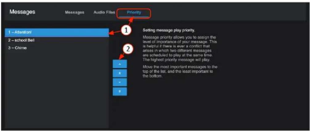
- Select the highest priority in the list and use the up arrow to move it to the top.
- Using the arrows, adjust the list to top down. The "1" denotes the priority order number.
Note: The Priority page saves your settings when you exit the page. The priority list order is also saved to the "+ NEW MESSAGE" list on the messages configuration page.

Atlas IED
1601 JACK MCKAY BLVD.
ENNIS, TEXAS 75119 U.S.A.
TELEPHONE: (800) 876-3333
SUPPORT@ATLASIED.COM
AtlasIED.com
Atmosphere
User Manual
GPIO Overview
The GPIO interface allows external controllers to trigger pre-configured functions, called "Actions," such as Routines, Scenes, Messages, Bell Schedules, GPO Presets and Room Combine. There are six standard and one High Priority input contact closure or voltage triggers. The High Priority input has additional settings specifically for public alert messaging or where emergency systems need to be coordinated with the audio system. There are two GPO voltage trigger outputs which internal faults can be selected to trigger. Or they can be configured in Output Presets to start a power sequencer, a projector and screen, or start/stop a third-party voltage activated system/device.
GPIO - Inputs
Setting Up a GPIO to Recall a Scene and/or Play a Message
In the UI, select the GPIO tab and the inputs page opens.
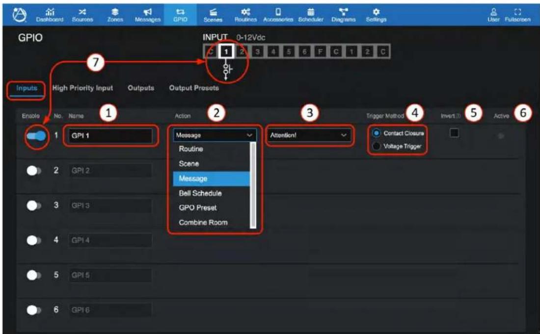
- Enter a name for the function in one of 6 GPI ports.
- Select the action type from the dropdown list: Routine, Scene, Message, Bell Schedule, GPO Preset, or Combine Room.
- Select the action desired in the dropdown list.
- Select the type of activation control; Contact Closure or Voltage Trigger.
- Select to invert the input port trigger. Selecting this will start the action unless the port is connected to common, either by a third-party device of relay or a jumper wire.
- Status indicator will light when port is triggered.
- Enable sets port number to accept input. When disabled, the action cannot be triggered.
- (below) Wiring port 1 with contact closure or voltage trigger connection. This can be a relay or latching switch. Example of contact closure: AtlasLED WPD-SWCC.

Atlas IED
1601 JACK MCKAY BLVD.
ENNIS, TEXAS 75119 U.S.A.
TELEPHONE: (800) 876-3333
SUPPORT@ATLASIED.COM
AtlasIED.com
Atmosphere
User Manual
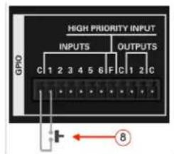
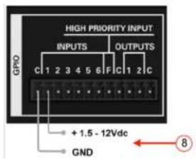
AtlasIED - WPD-SWCC Wiring Configuration
Hard Latching Push Switch ON/OFF, using remote DC power source
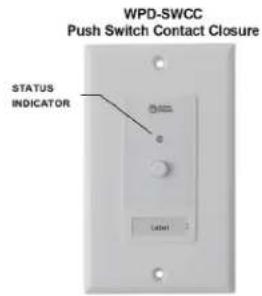
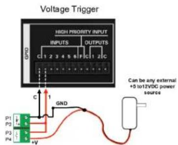
GPIO - Outputs
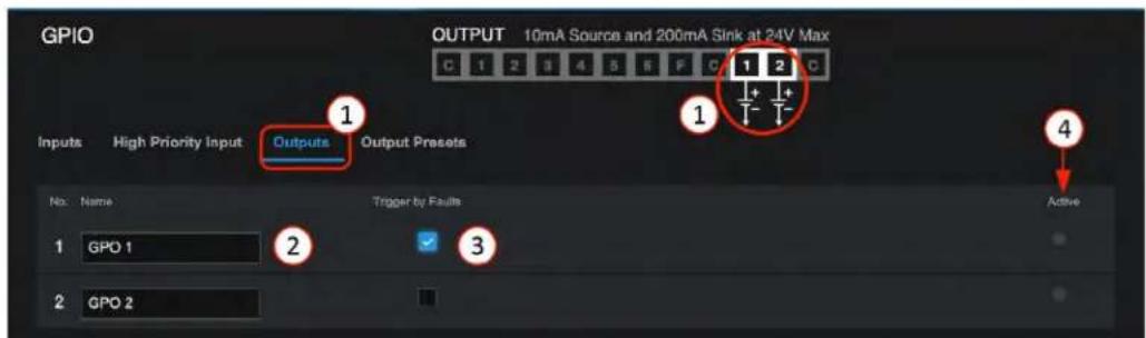
- GPO 1 & 2 are either high or low voltage logic outputs only.
- Enter a name for the function in one of 2 GPO ports.
- Select this to use system faults to trigger the GPO for external devices. When the system is in a fault state the GPO will be set high. When there are no faults the GPO will be set low.
- Status indicator will light when port is triggered.
Note: Go to "Output Presets" settings to: Set-High, Set-Low, Toggle, and Pulse adjustable in .1 sec increments
GPIO - Output Presets
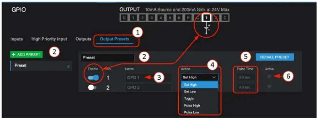
- Select GPIO output presets
- Enter a name for the function. Multiple presets can be configured.
- Identifies GPO port, name the port in GPIO outputs sub-tab.
- Select trigger type: Set High, Set Low, Toggle, Pulse High, Pulse Low.
- Set pulse time in .1 sec increments. "RECALL PRESET" will audition the action to confirm the setting is working.
- Status indicator will light when port is triggered. If timed, it will pulse on/off at the set pulse time.

Atlas IED
1601 JACK MCKAY BLVD.
ENNIS, TEXAS 75119 U.S.A.
TELEPHONE: (800) 876-3333
SUPPORT@ATLASIED.COM
AtlasIED.com
Atmosphere
User Manual
GPIO – High Priority Input
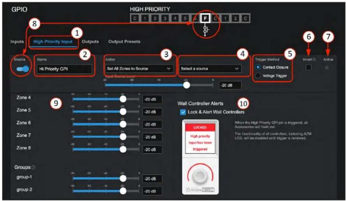
In the UI, select the GPIO tab then:
- Select High Priority input
- Enter a name for the function.
- Select the type of activation action. Selections are: Mute All Zones, Set All Zones to Source, or Play Message in All Zones.
- Depending on your selection in 3, select message or source desired from list. Select "Repeat Message Indefinitely" if desired.
- Select Contact Closure (CC) or Voltage Trigger (VT).
- Select Invert to reverse the logic action. Default CC is NO (normally open); When Invert is selected, NC (the trigger action will be active until you connect the port to common).
- Status indicator will light when port is triggered (Active).
- Enable sets High Priority port "F" to accept input.
- These faders allow setting the zone and group zone levels to use while Active.
- Select Wall Controller Lock & Alert status. When triggered, all accessories will flash red and functionality will be disabled until trigger is removed.
- (below) Example of wiring Port F to common with contact closure connection and a voltage trigger. This can be connected to a relay activated by an alarm system.
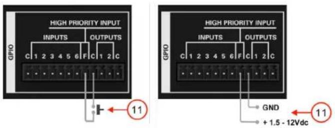

Atlas IED
1601 JACK MCKAY BLVD.
ENNIS, TEXAS 75119 U.S.A.
TELEPHONE: (800) 876-3333
SUPPORT@ATLASIED.COM
AtlasIED.com
Atmosphere
User Manual
Scenes Overview
The Scenes tab lets you add a name and save a group of settings that can be recalled by name. Scenes can be recalled in the following ways:
- By using the Scene UI to select it by name, then select Recall Scene.
- By setting it up as a GPIO Trigger Scene.
- By setting it up as a Scheduled Event in the scheduler.
- By triggering a scene from a C-ZSV controller.
- By adding and selecting it in a virtual wall controller.
Setting up a Scene
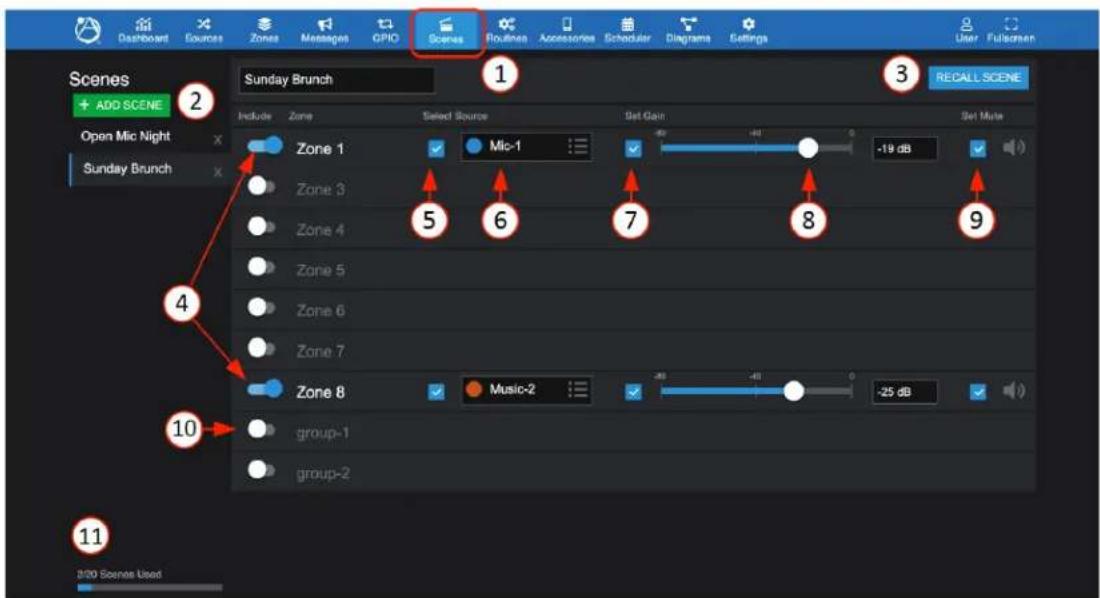
- In the UI, select the Scenes tab.
- Select Add New Scene, name the scene in the pop-up screen, and select OK.
- Recalls (triggers) an existing scene. (Executes settings 4-10.)
- Enable the output zones to be included in the scene.
- Select to apply source for any included zone if desired.
- Select audio source for each zone to include in the named scene.
- Select to apply gain or leave unselected for an accessory like C-V to adjust volume in the zone.
- Adjust desired gain.
- Select to apply mute if desired for that scene. To ensure the zone is not muted, be sure to include the mute state and save in unmuted state.
- Select to Include a saved group as part of a scene.
Note: Group settings will only apply if the group is currently combined. If the group is not combined, this section of the scene will be ignored. - The total set-up scenes out of a max of 20.

Atlas IED
1601 JACK MCKAY BLVD.
ENNIS, TEXAS 75119 U.S.A.
TELEPHONE: (800) 876-3333
SUPPORT@ATLASIED.COM
AtlasIED.com
Atmosphere
User Manual
Routines Overview
The AZM now has numerous capabilities called 'Actions'. An Action is either a Scene, Message, GPO Preset, Bell Schedule Recall, or Room Combine. Routines allow you to set up and save up to 20 groups of Actions and recall or "run" them as a single Action. A Routine can be triggered in the following ways:
- By selecting as a GPIO Trigger Routine. (See GPIO Tab for example of using a contact closure button)
- By selecting it as a Scheduled Event in the scheduler.
- By setting it up in the Actions tab in a C-ZSV controller.
- By setting it up in the Actions tab in a virtual wall controller.
Setting up a Routine
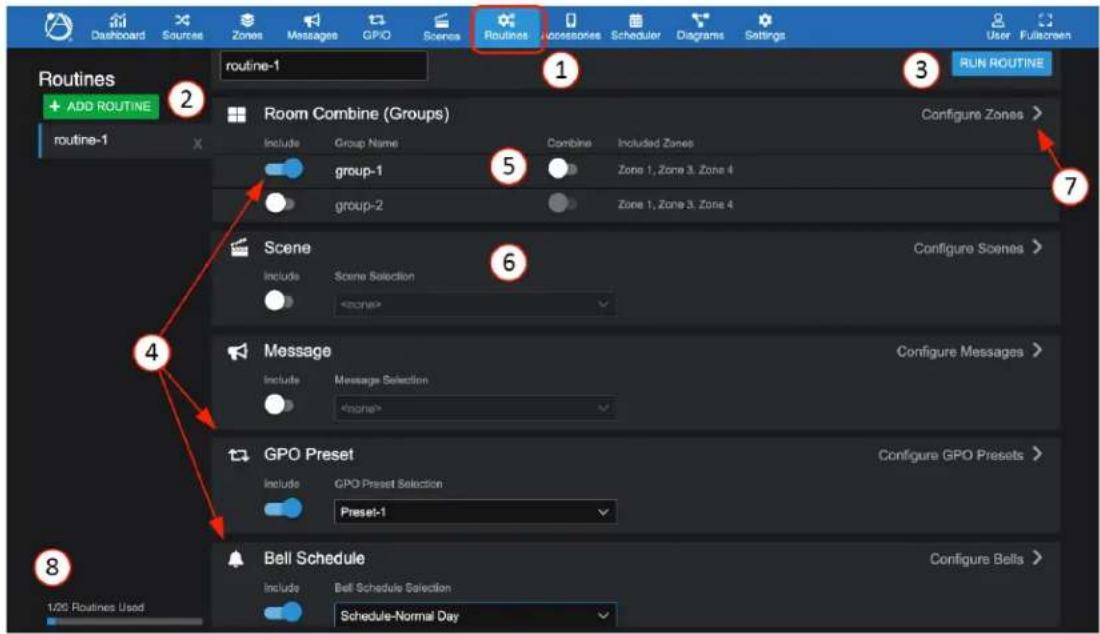
- In the UI, select the Routines tab.
- Select ADD ROUTINE, name the routine in the pop-up screen, and select OK.
- RUN ROUTINE= audition an existing routine, make some changes and rename/save. Note: Exiting page saves settings.
- Enable the actions to be included in the routine.
- Select to apply the combine action for any included groups if desired. In this example group-1 will be uncombined, and group-2 will be ignored.
- Select scene to include in the routine.
- Select ">" navigates to the specific set up pages for each action.
- The total set-up routines out of a max of 20.

Atlas IED
1601 JACK MCKAY BLVD.
ENNIS, TEXAS 75119 U.S.A.
TELEPHONE: (800) 876-3333
SUPPORT@ATLASIED.COM
AtlasIED.com
Atmosphere
User Manual
Accessories Overview
Six plug and play smart wall plate accessories can be populated on AZM accessory ports to add remote source inputs or provide zone control. Accessories include:
- 3 x audio inputs- balanced mic/line XLR, dual RCA stereo summed with 3.5mm, and Bluetooth® audio wall plate inputs.
- 2 x controllers- volume controls, volume controls with source select, scene recall, and message playback
- 1 x ambient noise sensor for Ambient Noise Compensation control.
Any control accessory can be daisy chained on a single cable digital bus and assigned to any zone, reducing installation wiring time and complexity. Virtual control can be established with any mobile device by QR code scanning.
Note: For audio wall plates A-XLR, A-RCA, and A-BT, see Audio Wall Plate Inputs earlier in this manual.
Controller Accessories
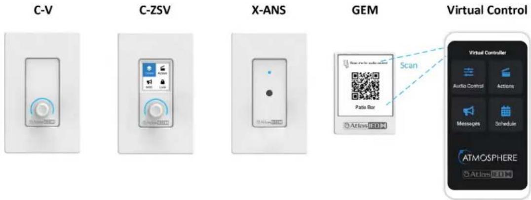
- C-V - Volume Control
- C-ZSV- Volume Control with Source select, scene recall, and message playback
- X-ANS - Ambient Noise Sensor for supplying ambient noise levels to the Ambient Noise Compensation algorithm
- GEM – Wall mountable frame/placard to hold a virtual wall controller QR code printed from the user interface. Controls for the QR code can be opted in the user interface.
The Accessories UI page is where you add and configure settings for the following:
- Virtual Controllers (Mobile) – Any mobile device can be turned into a controller by using the “+ ADD NEW” setup to create a QR code to scan and instantly use your mobile device to access the same features as a wired controller. (no app download required)
- Front Panel Display – Select QR Code to enlarge and scan with mobile device, a front panel UI screen will display access to control zones, sources, and volume levels.
- Accessory Ports A-B (AZM4) or Ports A-B-C-D (AZM8) – All wall plate accessories are connected to the AZM accessory ports. These ports populate as you connect the wired accessories and the AZM detects them. Once detected, they appear on the port as shown below.

Atlas IED
1601 JACK MCKAY BLVD.
ENNIS, TEXAS 75119 U.S.A.
TELEPHONE: (800) 876-3333
SUPPORT@ATLASIED.COM
AtlasIED.com
Atmosphere
User Manual
Accessories
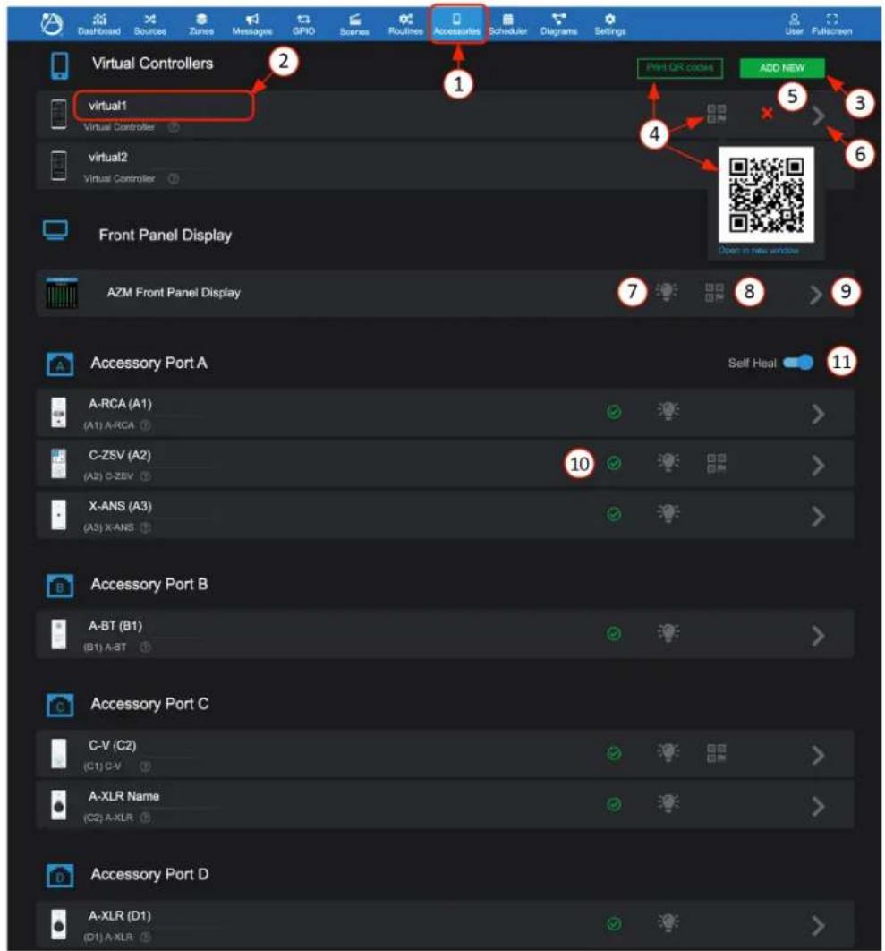
- Accessories tab
- Device name will display or can be entered. The name will populate the UI wherever device is referred to.
- “+ADD NEW” allows up to 25 virtual controllers to be added and configured.
- Selecting QR Code icon will pop-up a QR code to scan, or, select Print and print all configured QR codes, formatted for our GEM QR plaques. One is included with each AZM. Additional GEM plaques can be purchased in packs of five. See: https://www.atlasied.com/gem-5
Note: For QR control to work, mobile device must be connected to the same network as the AZM. It is also recommended to use a static IP on the AZM to ensure repeated reliable connection.
- "X" deletes virtual controller.
- Open the settings pages to configure the controller.
- Locate icon will cause an accessory connected device to flash to physically identify it. If left on, it will automatically shut off after 30 minutes.
- Front panel display OR code can be scanned and used as an additional virtual controller with the same access control as a C-ZSV.
- Select ">" to go to Settings to configure the front panel display.
- On the accessory ports, the wall plate icon image and name are displayed along with the status that lights up with a green check mark when wired accessories are successfully detected, updated, and ready for use on the port.
- After installing a system, switch on "Self-Heal" and the system will automatically retain the settings in the event a wall controller accessory requires replacement on a port.

Atlas IED
1601 JACK MCKAY BLVD.
ENNIS, TEXAS 75119 U.S.A.
TELEPHONE: (800) 876-3333
SUPPORT@ATLASIED.COM
AtlasIED.com
Atmosphere
User Manual
Setting up a virtual wall controller
General Settings Page
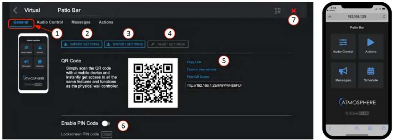
- General settings- select Accessories tab - Virtual Controllers - for Settings.
- Import Settings – this allows a saved configuration file to be imported to duplicate an existing setup.
- Export Settings – this saves the configuration file as a backup to use for importing.
- Reset Settings – chose from Soft Reset (back to default) or Reset QR code to create an updated QR.
- Various ways to use the QR codes, copy link, share link, open in new window, or print.
- Allows setting a four number PIN code to restrict access, if desired.
- Click "X" to delete virtual controller.
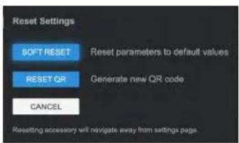
Audio Control Page
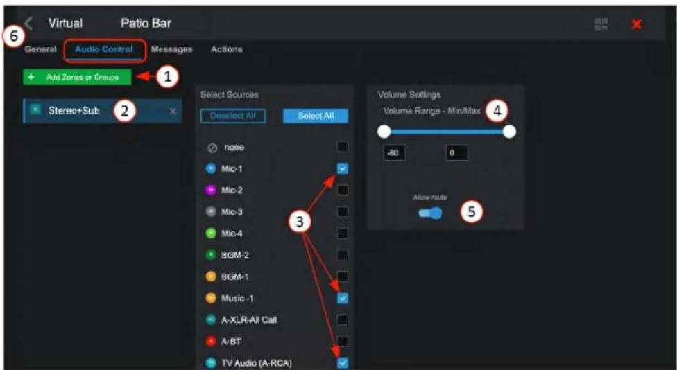
- Add zones and groups you want to control on the mobile device.
- Select the zones and groups to be controlled by the mobile device.
- Select input sources individually or all to be displayed as a selection list on mobile device.
- Set an acceptable range of volume to adjust.
- Set mute to allow it to be available on the mobile device to toggle.
- Click "<" icon to return to Accessory page.

Atlas IED
1601 JACK MCKAY BLVD.
ENNIS, TEXAS 75119 U.S.A.
TELEPHONE: (800) 876-3333
SUPPORT@ATLASIED.COM
AtlasIED.com
Atmosphere
User Manual
Virtual Wall Controller Setup – Audio Control
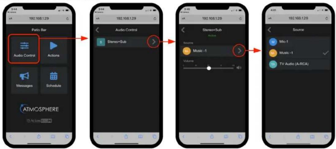
flowchart
graph TD
    A["Audio Control"] --> B["Audio Control"]
    B --> C["Audio + Sub"]
    C --> D["Music -1"]
    D --> E["Music -1"]
    E --> F["TV Audio (A-RCA)"]
Messages Page
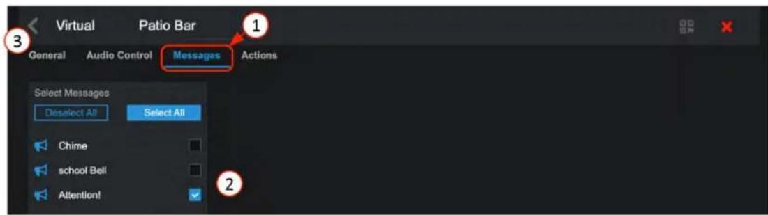
- Open Messages setup page.
- Select from the list of pre-configured messages to be included to control on the mobile device.
- Press return link "<" to exit page, save settings, and return to accessories main page.
Virtual Wall Controller Setup- Messages
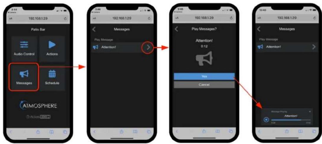
flowchart
graph TD
    A["3:44"] --> B["192.168.1.29"]
    B --> C["5:48"]
    C --> D["192.168.1.29"]
    D --> E["3:45"]
    E --> F["192.168.1.29"]
    F --> G["5:48"]
    G --> H["192.168.1.29"]
    H --> I["3:45"]
    I --> J["192.168.1.29"]
    J --> K["5:48"]
    K --> L["192.168.1.29"]
    L --> M["3:45"]
    M --> N["192.168.1.29"]
    N --> O["5:48"]
    O --> P["192.168.1.29"]

Atlas IED
1601 JACK MCKAY BLVD.
ENNIS, TEXAS 75119 U.S.A.
TELEPHONE: (800) 876-3333
SUPPORT@ATLASIED.COM
AtlasIED.com
Atmosphere
User Manual
Actions Page
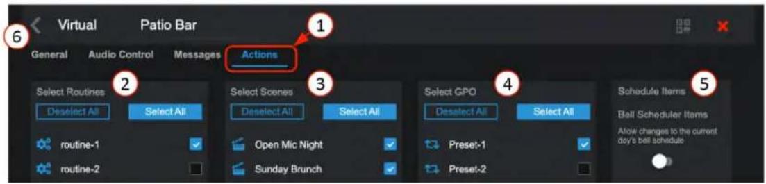
- Open Actions page.
- Select from the list of pre-configured routines to be included on mobile device.
- Select from the list of pre-configured scenes to be included on mobile device.
- Select from the list of pre-configured GPO presets to be included on mobile device.
- Bell Scheduler change – When enabled, this lets you make an on-the-spot change to the current day's schedule.
- Return "<" to Accessories page and scan QR code with mobile device. (Note: device must be on the same network as the AZM.) Open the UI in mobile device. Screen will show selections made for control.
Virtual Wall Controller Setup – Actions
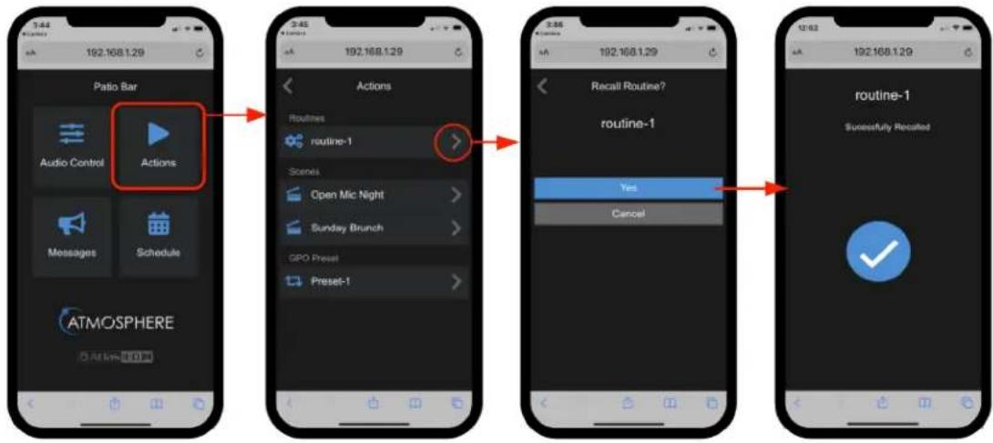
flowchart
graph TD
    A["Actions"] --> B["Audio Control"]
    A --> C["Actions"]
    D["Routine-1"] --> E["Open Mic Night"]
    D --> F["Sunday Brunch"]
    D --> G["GPO Presel"]
    D --> H["Preset-1"]
    I["Recall Route?"] --> J["Yes"]
    I --> K["Cancel"]
    L["routine-1"] --> M["Successfully Recalled"]
Virtual Wall Controller Setup - Schedule
The Schedule will show any scheduled events along with the bell schedule type expected for the day.
If "Schedule Items" above in virtual actions Setup is "Enabled", the daily bell schedule pre-configured exception schedules will be available as options.
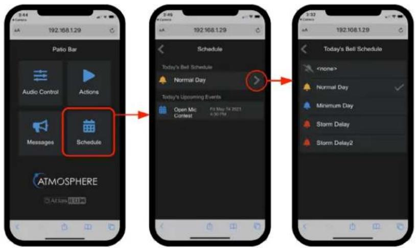

Atlas IED
1601 JACK MCKAY BLVD.
ENNIS, TEXAS 75119 U.S.A.
TELEPHONE: (800) 876-3333
SUPPORT@ATLASIED.COM
AtlasIED.com
Atmosphere
User Manual
Print, Assemble, Place, and Scan
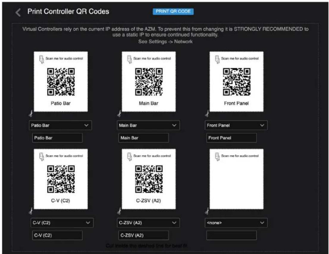
- After creating virtual controllers, go back to the Accessories main page and select "Print QR Codes." This will bring up a print window with all QR codes that have been configured. Print and cutout the zone QR codes you would like to put in zones to be scanned.
- Mount in GEM holder and place on wall. Additional GEM holders can be purchased in a pack of 5 at: https://www.atlasied.com/gem-5
- Scan with mobile device and have instant control of the selections assigned. (Note: device must be connected to the same network as the AZM.)
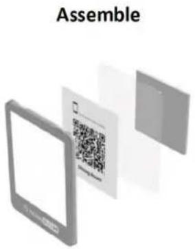
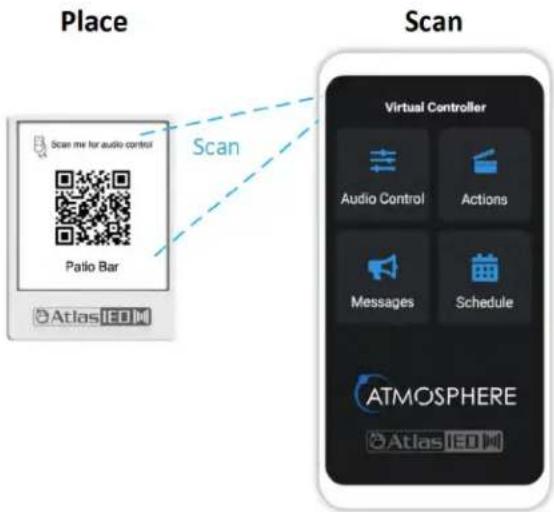

Atlas IED
1601 JACK MCKAY BLVD.
ENNIS, TEXAS 75119 U.S.A.
TELEPHONE: (800) 876-3333
SUPPORT@ATLASIED.COM
AtlasIED.com
Atmosphere
User Manual
Setting up Accessory Port wall controllers
Note: see Inputs - Audio Wall Plates section for A-XLR, A-RCA, and A-BT settings UI pages
General Settings Page for C-ZSV
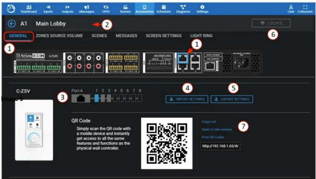
- The General Settings page shows the connected port, with settings pages for Zone Audio Control, Messages, Actions, Screen Settings, and Light Ring.
- Accessory name – displays the editable name for this accessory.
- Connected port ID, and location of the accessory on the port wiring bus (Port A-position 2).
- Import settings – allows a saved configuration file to be imported to duplicate an existing setup.
- Export settings – saves the configuration file as a backup or to use for importing.
- Reset settings – allows selecting between: reset to default values or reset parameters and reboot accessory.
- The locate icon can be clicked on or off causing the connected device to flash to physically identify its location. If left on, it will automatically shut off after 30 minutes. Additionally, pressing or turning the encoder on the controller will cancel the locate flashing.
- In addition to the wired wall controller a virtual wall controller is automatically created that emulates the settings by scanning the QR code. There are various ways to use the QR codes: Copy Link, Open in New Window, or Print the QR code for display in the GEM mounting frame.
Atmosphere
User Manual
Zones Audio Control Page
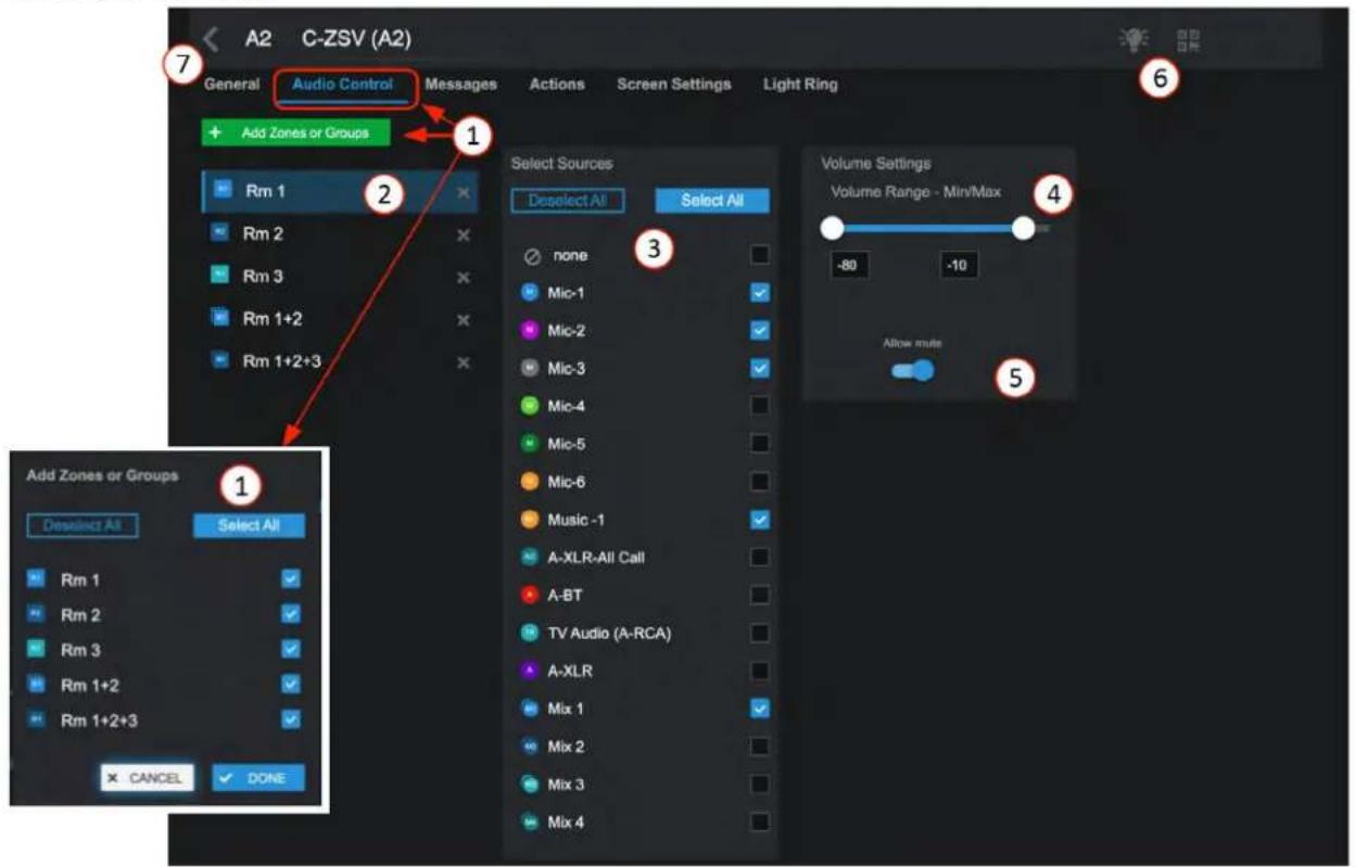
- Click on "+ Add Zones or Groups", in the popup, select what you want available in the list to control on the C-ZSV and-or virtual mobile device.
- In the list, select each of the zones or groups and complete #3, #4, & #5.
- Select input sources individually or select All to be displayed as a selection list on the C-ZSV and-or virtual controller.
- Set an acceptable range of volume to adjust.
- Set mute to allow it to be available on the mobile device to toggle.
- The locate icon can be clicked on or off and will cause the connected device to flash to physically identify its location. If left on, it will automatically shut off after 30 minutes. Additionally, pressing or turning the encoder on the controller will cancel the locate flashing. Click on the QR code symbol to display a QR code allowing a virtual controller to emulate the wall plate controller. Wall controllers automatically generate a QR code for a virtual controller.
- Select "<" icon to return to the Accessories page.
Atmosphere
User Manual
Messages Page
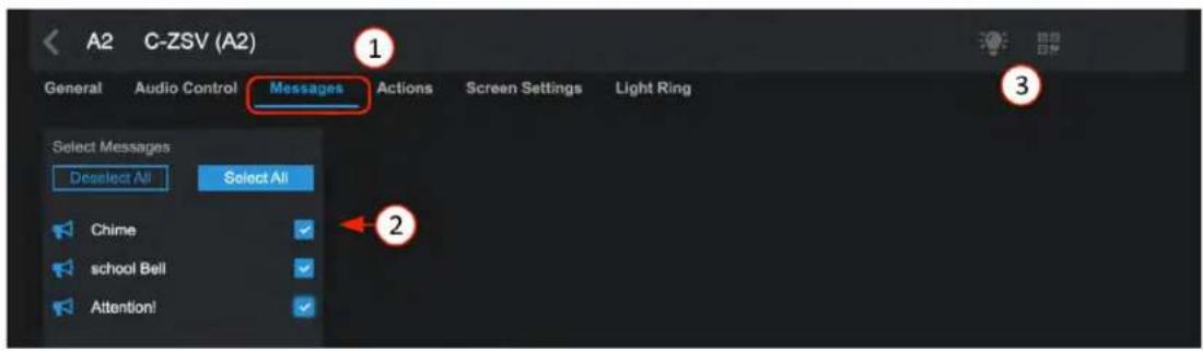
- Select Messages tab to open.
- Select the messages you want available for control from the C-ZSV and-or virtual mobile device.
- The light bulb locate icon can be clicked on or off causing the connected device to flash to physically identify its location. If left on, it will automatically shut off after 30 minutes, or will cancel when the controller encoder is used. If you see the QR code symbol and click on it, a QR code will display allowing a mobile virtual controller to emulate the wall plate controller.
Actions Page
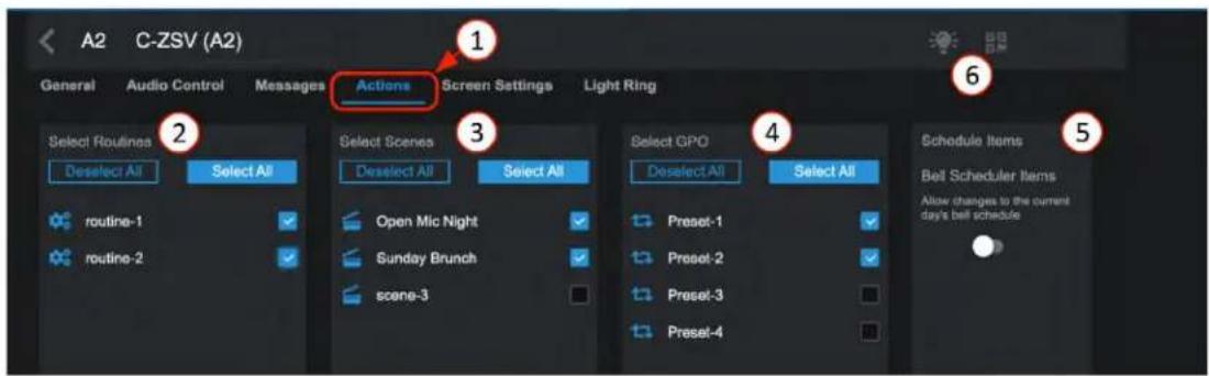
- Open Actions page
- Select from the list of pre-configured routines to be included on C-ZSV and mobile device.
- Select from the list of pre-configured scenes to be included on C-ZSV and mobile device.
- Select from the list of pre-configured GPO presets to be included on C-ZSV and mobile device.
- Bell Scheduler change – When enabled, this lets you make an on-the-spot change to the current day's schedule.
- The light bulb locate icon can be clicked on or off and will cause the connected device to flash to physically identify its location. If left on, it will automatically shut off after 30 minutes or will cancel when the controller encoder is used. If you see the QR code symbol and click on it, a QR code will display allowing a mobile virtual controller to emulate the wall plate controller.
Atmosphere
User Manual
Screen Settings Page
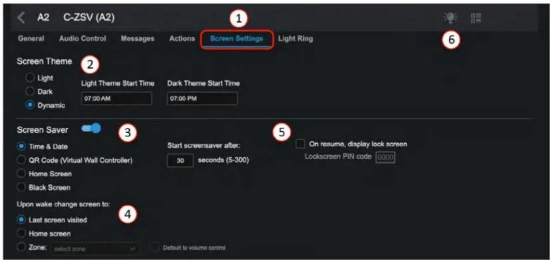
- Select Screen Settings tab to open.
- Select the theme for the C-ZSV display and time of day to change if desired.
- Set screen saver display and time to activate in X seconds.
- Select the behavior desired when it wakes.
- Set PIN code to restrict access to this controller if desired.
- The locate icon can be clicked on or off and will cause the connected device to flash to physically identify its location. If left on, it will automatically shut off after 30 minutes or will cancel when the controller encoder is used. If you see the QR code symbol and click on it, a QR code will display allowing a mobile virtual wall controller to emulate the wall plate controller.

Light Ring Settings Page
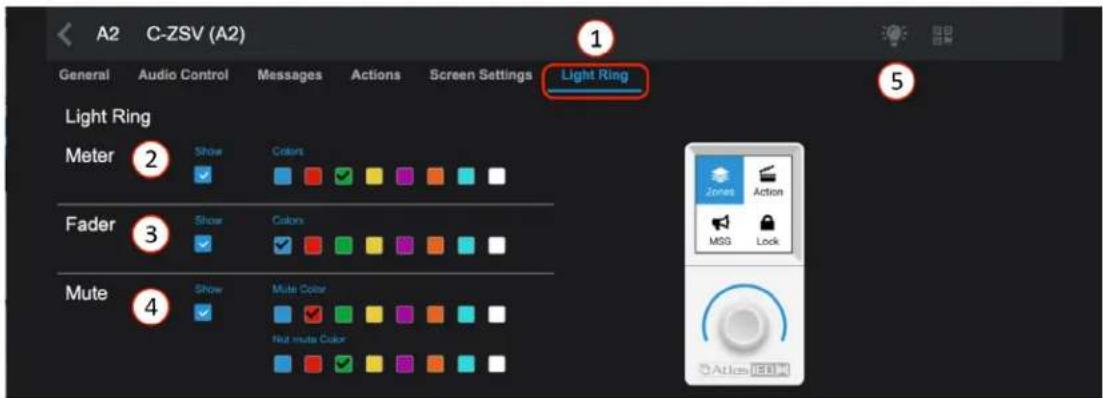
- Select Light Ring tab to open.
- Select to show and color of light ring for Meter level mode.
- Select to show and color of light ring for Fader level mode.
- Select to show and color of light ring for Mute toggle On/Off mode.
- The locate icon can be clicked on or off and will cause the connected device to flash to physically identify its location. If left on, it will automatically shut off after 30 minutes or will cancel when the controller encoder is used. If you see the QR code symbol and click on it, a QR code will display allowing a mobile virtual wall controller to emulate the wall plate controller.

Atlas IED
1601 JACK MCKAY BLVD.
ENNIS, TEXAS 75119 U.S.A.
TELEPHONE: (800) 876-3333
SUPPORT@ATLASIED.COM
AtlasIED.com
Atmosphere
User Manual
General Settings Page for C-V
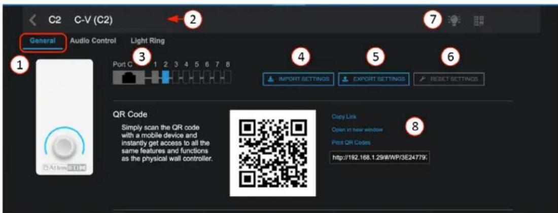
- The General Settings page shows the connected port, with settings pages for Zone Audio Control, and Light Ring.
- Accessory Name – displays the editable name for this accessory.
- Connected port ID, and location of the accessory on the port wiring bus (Port C-position 2).
- Import Settings – allows a saved configuration file to be imported to duplicate an existing setup.
- Export Settings – saves the configuration file as a backup or to use for importing.
- Reset Settings – allows selecting between: Reset to default values or Reset parameters and reboot accessory.
- The locate icon can be clicked on or off causing the connected device to flash to physically identify its location. If left on, it will automatically shut off after 30 minutes or will cancel when the controller encoder is used.
- In addition to the wired wall controller a virtual controller is automatically created that emulates the settings by scanning the QR code. There are various ways to use the QR codes: Copy Link, Open in New Window, or Print the QR code for display in the GEM mounting frame.
Atmosphere
User Manual
Audio Control Page
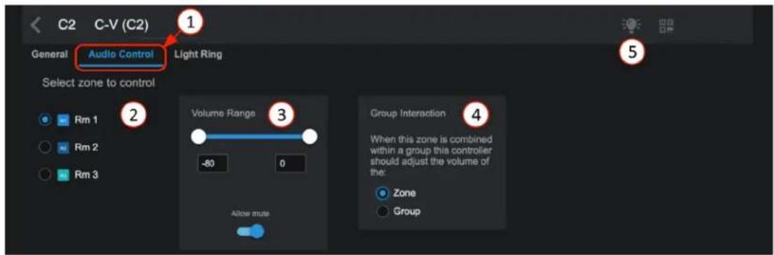
- The C-V acts like a traditional zone output volume controller. The Zone tab opens the list of zones available for control.
- Select the zones to be displayed for control by the C-V and-or mobile device.
- Set an acceptable range of volume to adjust. Set mute to allow it to be available on the C-V or mobile device to toggle.
- Select the control behavior when controller is combined in a group or zone.
- The locate icon can be clicked on or off causing the connected device to flash to physically identify its location. If left on, it will automatically shut off after 30 minutes or will cancel when the controller encoder is used.
Light Ring Settings Page
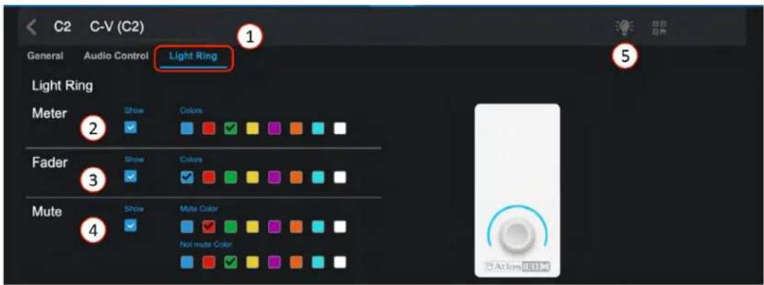
- Select Light Ring tab to open.
- Select to show and color of light ring for Meter level mode.
- Select to show and color of light ring for Fader level mode.
- Select to show and color of light ring for Mute toggle On/Off mode.
- The locate icon can be clicked on or off causing the connected device to flash to physically identify its location. If left on, it will automatically shut off after 30 minutes or will cancel when the controller encoder is used.

Atlas IED
1601 JACK MCKAY BLVD.
ENNIS, TEXAS 75119 U.S.A.
TELEPHONE: (800) 876-3333
SUPPORT@ATLASIED.COM
AtlasIED.com
Atmosphere
User Manual
General Settings Page for X-ANC
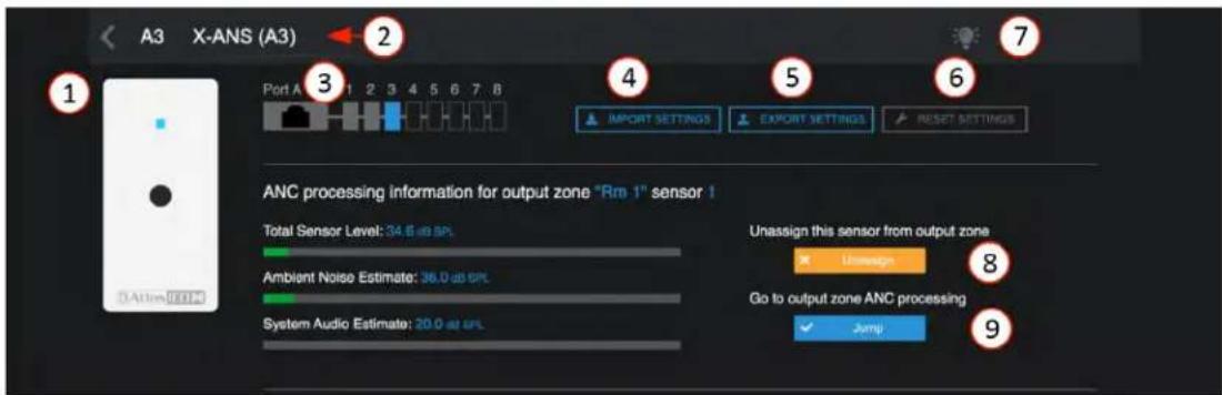
- The General Settings page shows the connected accessory port.
- Accessory Name – displays the editable name for this accessory.
- Connected Port ID, and location of the accessory on the port wiring bus. (Port A, position 3.)
- Import Settings – allows a saved configuration file to be imported to duplicate an existing setup.
- Export Settings – saves the configuration file as a backup or to use for importing.
- Reset Settings – allows selecting between: Reset to default values or Reset parameters and reboot accessory.
- The locate icon can be clicked on or off causing the connected device to flash to physically identify its location. If left on, it will automatically shut off after 30 minutes or will cancel when the controller encoder is used.
- The ANC processing data is shown in real time along with a button to unassign the ANC from the assigned Zone.
- A jump button takes you directly to the assigned zone ANC settings page to make adjustments. From the ANC settings page it also has a link on the sensor noise level meter " >" that returns you to this Accessory page.

Plug and Play Accessories Connection Rules
To guarantee good performance of all connected accessories, follow these rules:
- Use CAT5e or CAT6 non-shielded cable (see cabling section) to connect accessories to the host processor bus-ports.
- Up to 8 accessories can be daisy chained from a single port.
- The "IN" port is connected to the upstream device (AZM or another accessory). (see image rule 3)
- The maximum cable length from the AZM to the last accessory on the chain is 1000'(305m). (see image rule 4)
- One audio wall plate (A-XLR, A-RCA, A-BT) can be used per bus-port. (see image rule 5)
- Up to 16 accessories can be connected to a single AZM. (see image rule 6)
- Up to 12 QR code virtual controllers can be used in addition to wired accessories.
Image Rule 3
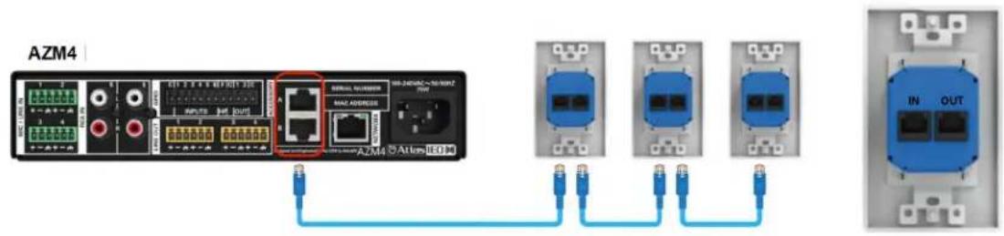

Atlas IED
1601 JACK MCKAY BLVD.
ENNIS, TEXAS 75119 U.S.A.
TELEPHONE: (800) 876-3333
SUPPORT@ATLASIED.COM
AtlasIED.com
Atmosphere
User Manual
Image Rule 4
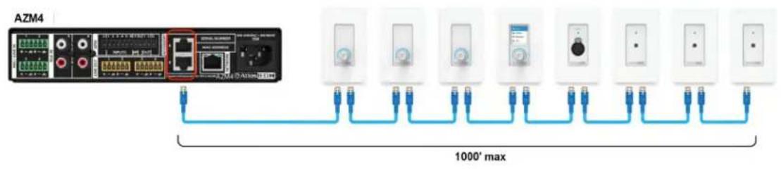
Image Rule 5
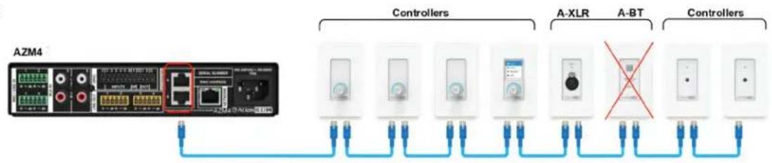
flowchart
graph LR
    A["AZM4"] --> B["Controllers"]
    A --> C["A-XLR"]
    A --> D["A-BT"]
    B --> E["Switch"]
    C --> F["Switch"]
    D --> G["Switch"]
    E --> H["Blue Link"]
    F --> I["Blue Link"]
    G --> J["Blue Link"]
    style A fill:#f9f,stroke:#333
    style B fill:#ccf,stroke:#333
    style C fill:#ccf,stroke:#333
    style D fill:#ccf,stroke:#333
    style E fill:#dfd,stroke:#333
    style F fill:#dfd,stroke:#333
    style G fill:#dfd,stroke:#333
    style H fill:#dfd,stroke:#333
    style I fill:#dfd,stroke:#333
    style J fill:#dfd,stroke:#333
↑
Image Rule 6
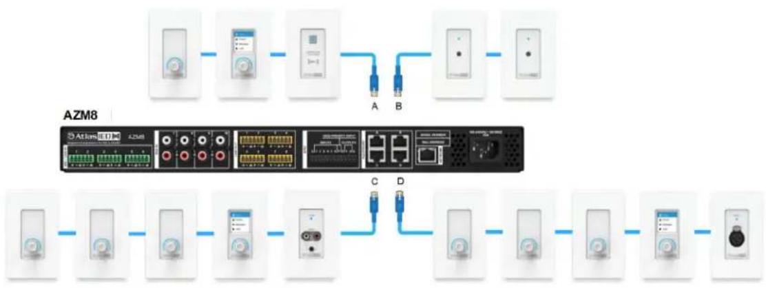
flowchart
graph LR
    subgraph AWS8
        A1["Device 1"] --> A2["Device 2"]
        A2 --> A3["Device 3"]
        A3 --> A4["Device 4"]
        A4 --> A5["Device 5"]
        A5 --> A6["Device 6"]
        A6 --> A7["Device 7"]
        A7 --> A8["Device 8"]
    end

    subgraph AWS8
        B1["Device 1"] --> B2["Device 2"]
        B2 --> B3["Device 3"]
        B3 --> B4["Device 4"]
        B4 --> B5["Device 5"]
        B5 --> B6["Device 6"]
        B6 --> B7["Device 7"]
        B7 --> B8["Device 8"]
    end

    A1 -.-> B1
    A2 -.-> B2
    A3 -.-> B3
    A4 -.-> B4
    A5 -.-> B5
    A6 -.-> B6
    A7 -.-> B7
    A8 -.-> B8
    B1 -.-> C1
    B2 -.-> C2
    B3 -.-> C3
    B4 -.-> C4
    B5 -.-> C5
    B6 -.-> C6
    B7 -.-> C7
    B8 -.-> C8
    C1 -.-> D1
    C2 -.-> D2
    C3 -.-> D3
    C4 -.-> D4
    C5 -.-> D5
    C6 -.-> D6
    C7 -.-> D7
    C8 -.-> D8
    C9 -.-> D9
    D1 -.-> E1
    D2 -.-> E2
    D3 -.-> E3
    D4 -.-> E4
    D5 -.-> E5
    D6 -.-> E6
    D7 -.-> E7
    D8 -.-> E8
    D9 -.-> E9
    E1 -.-> F1
    E2 -.-> F2
    E3 -.-> F3
    E4 -.-> F4
    E5 -.-> F5
    E6 -.-> F6
    E7 -.-> F7
    E8 -.-> F8
    E9 -.-> F9
Atmosphere
User Manual
Scheduler
The scheduler allows scheduling event actions just like scheduling a meeting on a calendar. Actions can be configured to take place in several ways when the Event Date/Time/Start-Stop takes place. Once scheduled, the event will show up on your dashboard as an upcoming event. The event log (Settings>Event Log) will show scheduled events that have taken place to confirm it is working.
Steps to create a scheduled event
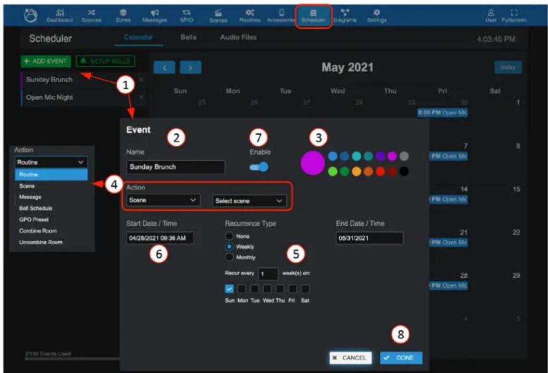
- When " + Add Event" is clicked, a popup page will open allowing configuration of the event profile.
- Give the event a name.
- Select a Color – shows event as a color on calendar and dashboard.
- Select type of event from the pre-configured actions list. Actions include: Routine, Scene, Message, Bell Schedule, GPO Preset, or Combine-Uncombine a zone group.
- Select recurrence type and define days.
- Enter event start date/time and end date/time.
- Event Enable – Note: time starts as soon as you enable.
- Select DONE to save settings, add to calendar, and see in dashboard as an upcoming event.

Atlas IED
1601 JACK MCKAY BLVD.
ENNIS, TEXAS 75119 U.S.A.
TELEPHONE: (800) 876-3333
SUPPORT@ATLASIED.COM
AtlasIED.com
Atmosphere
User Manual
Scheduler Calendar
Once an event is created, the calendar will populate with the named events and the dashboard show an "Upcoming Events" list. To make a change to any scheduled day, simply click on the calendar event and make the change in the popup settings screen.
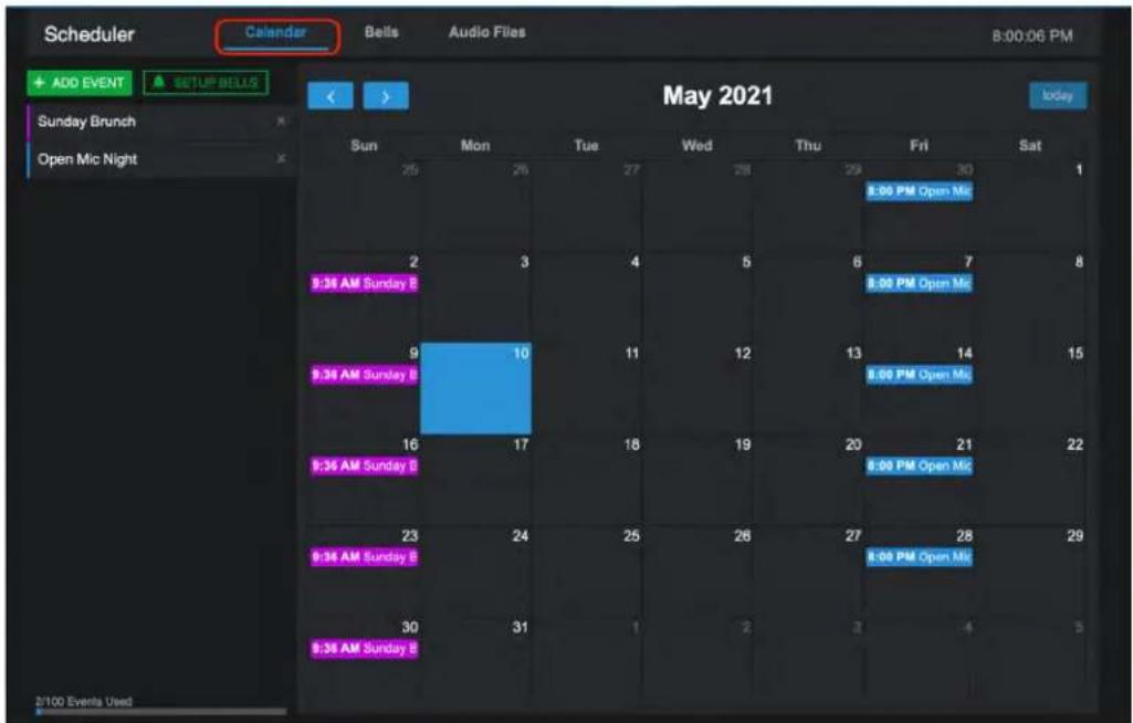
Steps to add a bell schedule
- Go to the Bells tab and click "+ADD BELL SCHEDULE".
- Fill in the daily schedule name and times.
- Select an audio file to play.
- Select zones box and a popup list of zones allows assignment of zones and levels.
- Duplicate the line can help speed up creating the schedule. "X" deletes line.
"Duplicate Schedule" will copy the entire same schedule to the Bell Schedule list, for editing. - Select Add new bell to add a blank line to fill out.
Note: Consider creating exception bell schedules to select from: ex. Storm Delay; Minimum Day; Assembly, etc. Also, see "Planner" access user level in Settings > User Accounts.
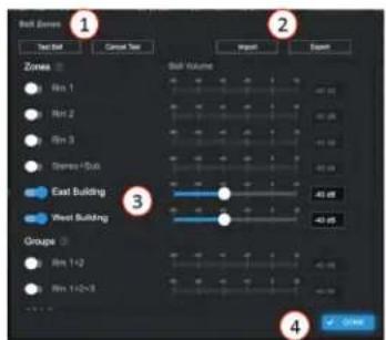
4 - Zones popup settings for each bell
- In-zone bell test ON.
- Cancel bell test.
- Select zone for this bell and adjust level.
- Select done to save and exit pop-up.
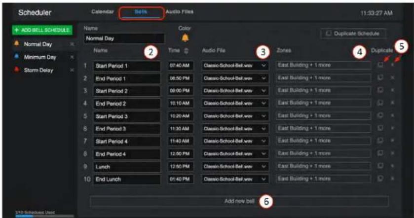

Atlas IED
1601 JACK MCKAY BLVD.
ENNIS, TEXAS 75119 U.S.A.
TELEPHONE: (800) 876-3333
SUPPORT@ATLASIED.COM
AtlasIED.com
Atmosphere
User Manual
Calendar - Set Up Bells
After creating the daily bell schedules, use SETUP BELLS to add to the calendar.
- On the Calendar tab, select SETUP BELLS.
- Enter start/end date.
- Select the desired bell schedule from the list for each day of the week.
- Continue to add weeks for the desired range.
- Select when done and calendar will populate.
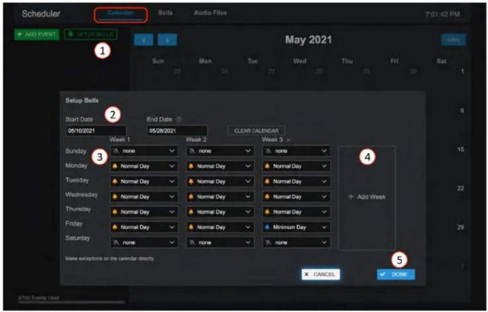
Calendar – Schedule Exceptions
To make a change to a specific day for an exception in the calendar, simply select the schedule directly and select the schedule change from the list of bell schedules. Note: See Settings > User Accounts – Planner Level.
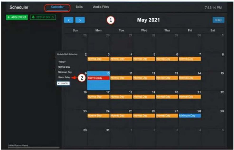

Atlas IED
1601 JACK MCKAY BLVD.
ENNIS, TEXAS 75119 U.S.A.
TELEPHONE: (800) 876-3333
SUPPORT@ATLASIED.COM
AtlasIED.com
Atmosphere
User Manual
Diagrams

Connection Diagram
In the UI, select the Diagrams icon to open the diagram type selection page. Choose from Connection Diagram or Block Diagram.
The Connection Diagram automatically populates all inputs and outputs as they are named. It also allows text fields for editing each one, including a notes window for network and GPIO settings. It can be printed as a system reference document for the project.
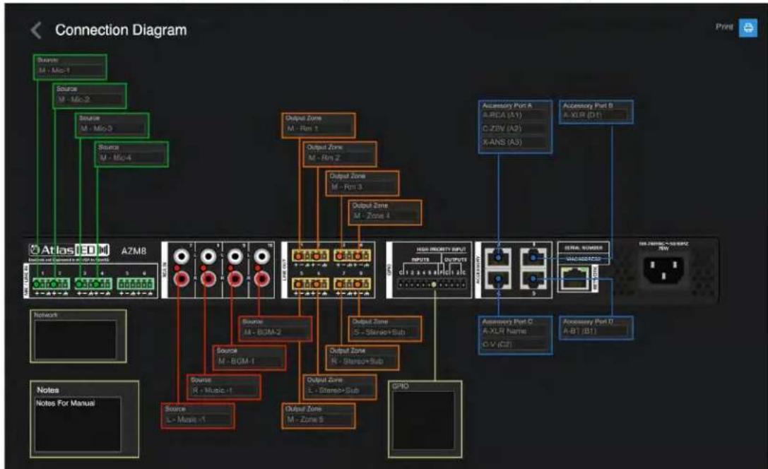
flowchart
graph TD
    A["Atlas LED"] -->|Source M - Micro-1| B["A2M8"]
    A -->|Source M - Micro-2| B
    A -->|Source M - Micro-3| B
    A -->|Source M - Micro-4| B
    B --> C["Network"]
    B --> D["Notes"]
    B --> E["Notes For Manual"]
    C --> F["Source R - Music-1"]
    D --> G["Source L - Music-1"]
    E --> H["Source M - BGM-1"]
    F --> I["Output Zone M - Rsm 1"]
    G --> J["Output Zone M - Rsm 2"]
    H --> K["Output Zone M - Rsm 3"]
    I --> L["Output Zone M - Rsm 4"]
    J --> M["Output Zone M - Rsm 5"]
    K --> N["High Output Input"]
    L --> N
    M --> N
    N --> O["OUTPUT INPUTS"]
    O --> P["OUTPUT INPUTS"]
    P --> Q["OUTPUT INPUTS"]
    Q --> R["OUTPUT INPUTS"]
    R --> S["OUTPUT INPUTS"]
    S --> T["OUTPUT INPUTS"]
    T --> U["OUTPUT INPUTS"]
    U --> V["OUTPUT INPUTS"]
    V --> W["OUTPUT INPUTS"]
    W --> X["OUTPUT INPUTS"]
    X --> Y["OUTPUT INPUTS"]
    Y --> Z["OUTPUT INPUTS"]
    Z --> AA["OUTPUT INPUTS"]
    AA --> AB["OUTPUT INPUTS"]
    AB --> AC["OUTPUT INPUTS"]
    AC --> AD["OUTPUT INPUTS"]
    AD --> AE["OUTPUT INPUTS"]
    AE --> AF["OUTPUT INPUTS"]
    AF --> AG["OUTPUT INPUTS"]
    AG --> AH["OUTPUT INPUTS"]
    AH --> AI["OUTPUT INPUTS"]
    AI --> AJ["OUTPUT INPUTS"]
    AJ --> AK["OUTPUT INPUTS"]
    AK --> AL["OUTPUT INPUTS"]
    AL --> AM["OUTPUT INPUTS"]
    AM --> AN["OUTPUT INPUTS"]
    AN --> AO["OUTPUT INPUTS"]
    AO --> AP["OUTPUT INPUTS"]
    AP --> AQ["OUTPUT INPUTS"]
    AQ --> AR["OUTPUT INPUTS"]
    AR --> AS["OUTPUT INPUTS"]
    AS --> AT["OUTPUT INPUTS"]
    AT --> AU["OUTPUT INPUTS"]
    AU --> AV["OUTPUT INPUTS"]
    AV --> AW["OUTPUT INPUTS"]
    AW --> AX["OUTPUT INPUTS"]
    AX --> AY["OUTPUT INPUTS"]
    AY --> AZ["OUTPUT INPUTS"]
    AZ --> BA["OUTPUT INPUTS"]
    BA --> BB["OUTPUT INPUTS"]
    BB --> BC["OUTPUT INPUTS"]
    BC --> BD["OUTPUT INPUTS"]
    BD --> BE["OUTPUT INPUTS"]
    BE --> BF["OUTPUT INPUTS"]
    BF --> BG["OUTPUT INPUTS"]
    BG --> BH["OUTPUT INPUTS"]
    BH --> BI["OUTPUT INPUTS"]
    BI --> BJ["OUTPUT INPUTS"]
    BJ --> BK["OUTPUT INPUTS"]
    BK --> BL["OUTPUT INPUTS"]
    BL --> BM["OUTPUT INPUTS"]
    BM --> BN["OUTPUT INPUTS"]
    BN --> BO["OUTPUT INPUTS"]
    BO --> BP["OUTPUT INPUTS"]
    BP --> BQ["OUTPUT INPUTS"]
    BQ --> BR["OUTPUT INPUTS"]
    BR --> BS["OUTPUT INPUTS"]
    BS --> BT["OUTPUT INPUTS"]
    BT --> BU["OUTPUT INPUTS"]
    BU --> BV["OUTPUT INPUTS"]
    BV --> BW["OUTPUT INPUTS"]
Block Diagram
The Block Diagram shows basic signal processing flow functions. It can be printed to go along with the connection diagram.
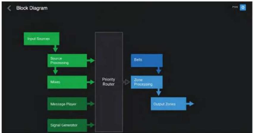
flowchart
graph TD
    A["Input Sources"] --> B["Source Processing"]
    B --> C["Mixes"]
    C --> D["Message Player"]
    D --> E["Signal Generator"]
    E --> F["Priority Router"]
    F --> G["Belts"]
    G --> H["Zone Processing"]
    H --> I["Output Zones"]

Atlas IED
1601 JACK MCKAY BLVD.
ENNIS, TEXAS 75119 U.S.A.
TELEPHONE: (800) 876-3333
SUPPORT@ATLASIED.COM
AtlasIED.com
Atmosphere
User Manual
Settings Page Overview
The Settings page is where all the device settings are located for configuration, updating, saving, and troubleshooting.
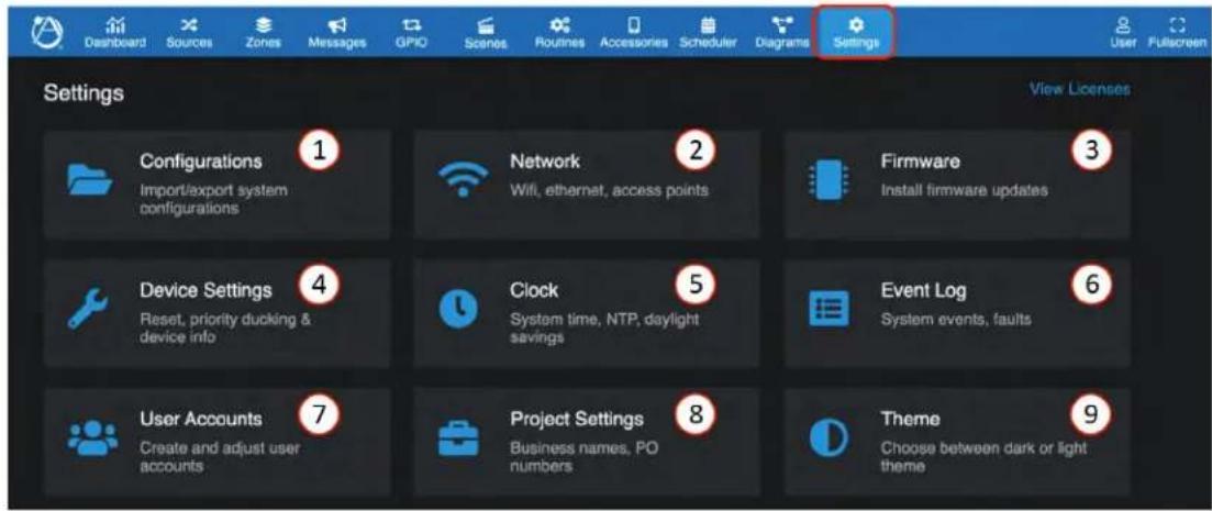
1. Configurations
This page provides utilities to back-up, import, and clone system configurations settings to distribute to other AZM devices.
- Import – click on import and find the saved system configuration file (.azm) on the pc where it was saved. Select file and it will upload to the AZM. Green check marks show files that will overwrite with uploaded settings. Note: it does not overwrite Network Settings, Error Log, and Audio Files.
- Distribution Copy – exports green checked device settings for distribution. Excludes Network Settings, Error Log, ANC Auto Mode, User Accounts, and Accessories.
- Backup Copy— creates a backup file for import of this device's green check marked settings, excluding Network Settings, Error Log, and Audio Files.
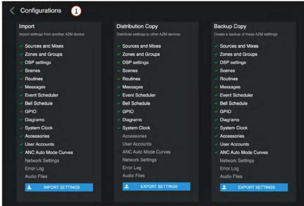

Atlas IED
1601 JACK MCKAY BLVD.
ENNIS, TEXAS 75119 U.S.A.
TELEPHONE: (800) 876-3333
SUPPORT@ATLASIED.COM
AtlasIED.com
Atmosphere
User Manual
2. Network
The left panel is the wired connection and the right panel is the wireless connection. Both can be connected at the same time, with different IP addresses. In addition, the wireless can be configured as an access point to directly connect to the UI when a network isn't available. This is useful when setting up the device prior to being on-site for install or if the site doesn't yet have an active connection. Default setting is DHCP. To set up Static IP, enter the address, subnet mask, and default gateway, then press "UPDATE". A popup message will verify you want to reboot to save configuration. The IP address is displayed at the top of the front panel display.
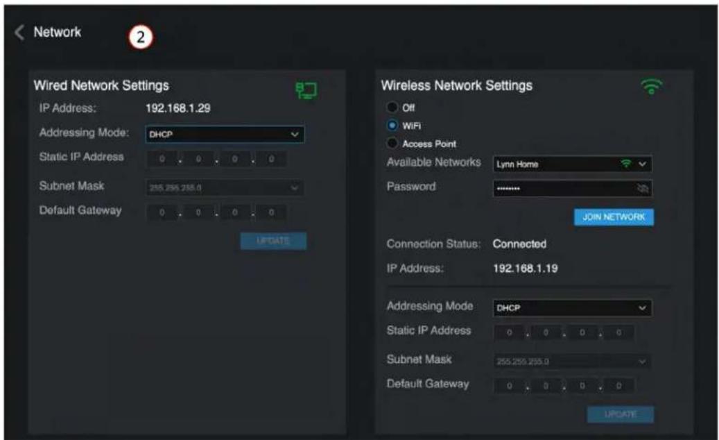
3. Firmware
To review the firmware version and update if needed. It is recommended to save a backup configuration file prior to updating. Visit atlasied.com to download the latest firmware.
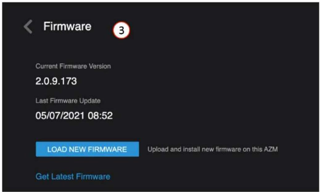

Atlas IED
1601 JACK MCKAY BLVD.
ENNIS, TEXAS 75119 U.S.A.
TELEPHONE: (800) 876-3333
SUPPORT@ATLASIED.COM
AtlasIED.com
Atmosphere
User Manual
4. Device Settings
This is where you can find global settings.
- At the top is CPU usage meter and operational up timer.
-
Priority Ducking Dynamics setup – these settings adjust all ducking behavior system wide.
-
Device Factory Reset – reverts all settings back to factory default values, including the network, which will revert to DHCP. The firmware version will remain unchanged.
- Device Reset Users – reverts user account settings back to default, all other settings remain unchanged. Reboot – reboots the entire system including the accessories retaining the configuration set up.
- Accessory Reset – soft reset of all connected accessories.
- Accessory Reboot-reboots all connected accessories.
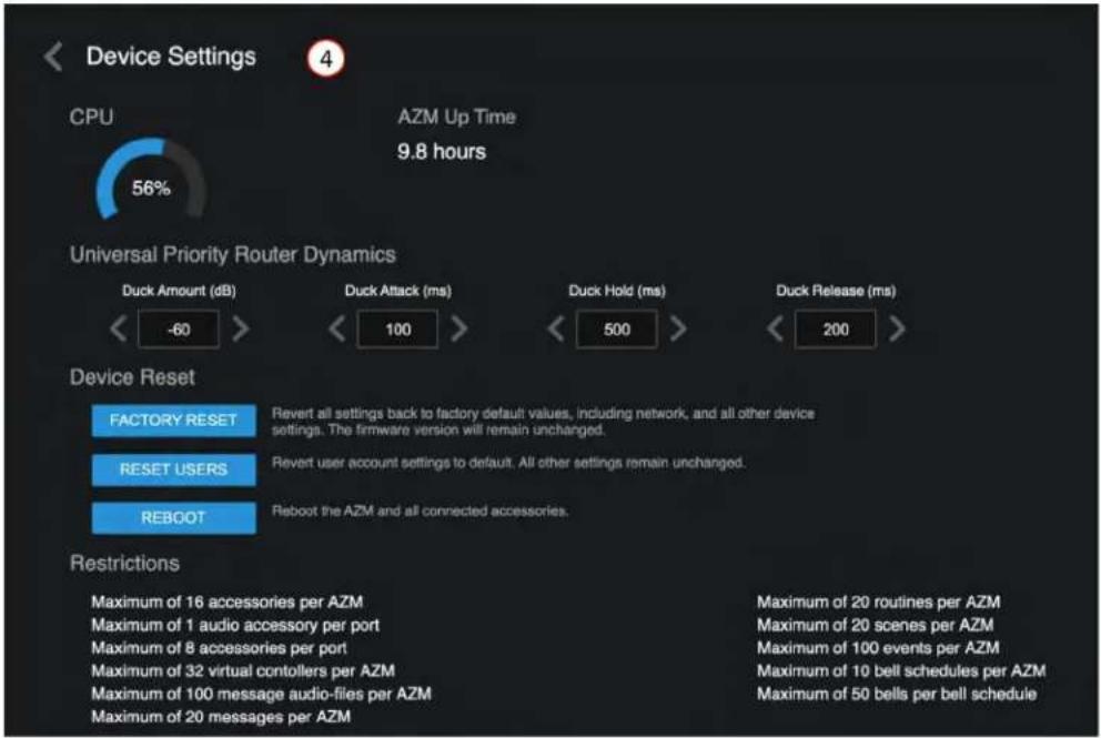
5. Clock
There are three ways to set the clock, select time zone region, and automatic daylight savings adjustment.
5a) Manual – select Date/Time window and chose date from calendar and scroll time, "SET TIME" to save.
5b) Automatic NTP – click NTP Sync Now to refresh sync. Indicates done with a green check mark.
5c) Select NTP Server – set up or change NTP server URL and confirm sync.
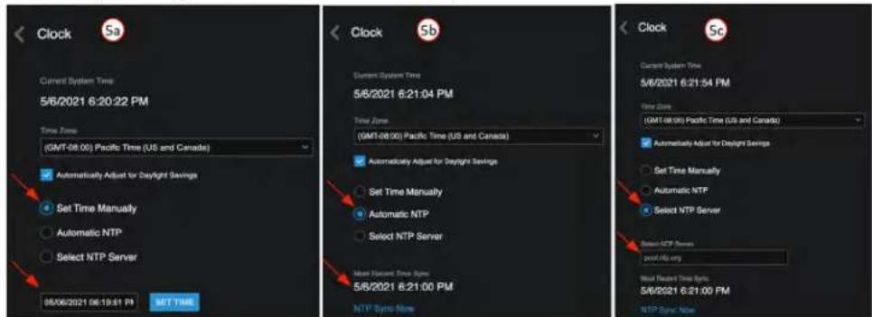

Atlas IED
1601 JACK MCKAY BLVD.
ENNIS, TEXAS 75119 U.S.A.
TELEPHONE: (800) 876-3333
SUPPORT@ATLASIED.COM
AtlasIED.com
Atmosphere
User Manual
6. Event Log
Event Log is where scheduled events and faults are logged, and time/date stamped.
The tool bar allows you to sort by Time/Date, Type, and Detail, to assist searching for specific events.
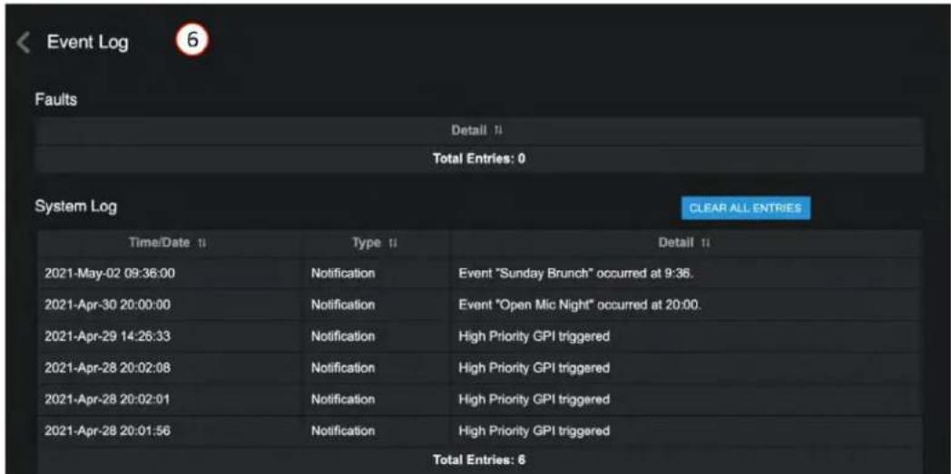
7. User Account
Manage registered user accounts. The default login is "admin, admin". After the first login, follow the onscreen instructions to change the default password. This will set up a user account.
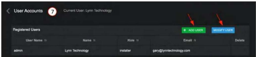
User Account Setup
After setting up an initial installer account, additional user accounts can be added or modified using "+ADD USER" or "MODIFY USER". There are four Role categories that determine access level:
- Installer: access to everything
- Manager: access to everything except for source/ zone DSP settings
- Planner: calendar only (events and bell scheduler)
- Associate: zone control only.
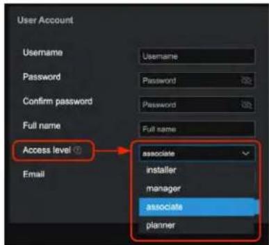

Atlas IED
1601 JACK MCKAY BLVD.
ENNIS, TEXAS 75119 U.S.A.
TELEPHONE: (800) 876-3333
SUPPORT@ATLASIED.COM
AtlasIED.com
Atmosphere
User Manual
8. Project Settings
Name the project, AZM device name, and make any specific notes associated with the project, network, or GPIO settings. Note: These notes will also populate the printable connection diagram notes.
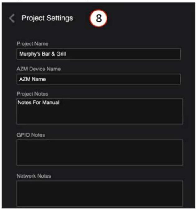
9. Theme
Select Light/Dark background theme
Note: This selection is also part of the initial log-in.
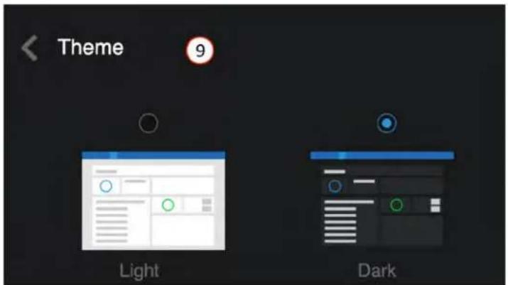
Atmosphere
User Manual
Front Panel Display Menu Tree
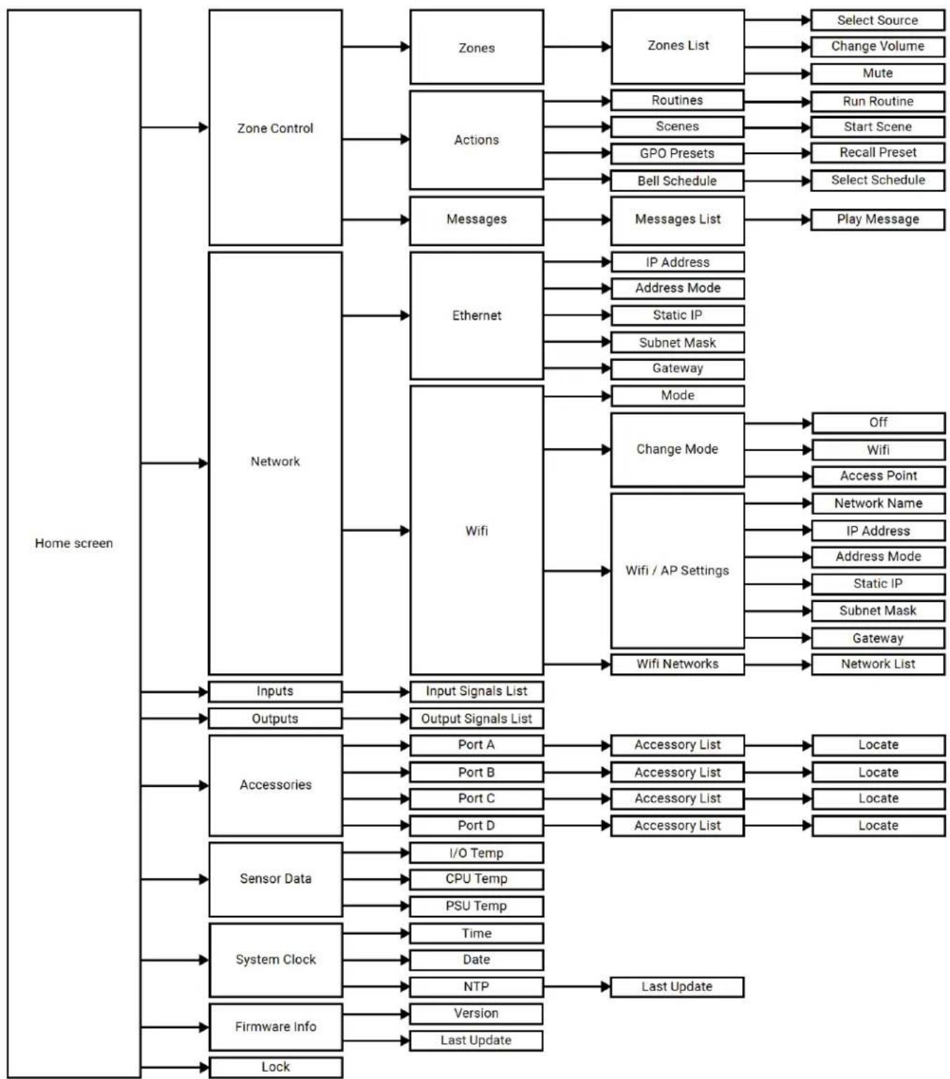
flowchart
graph TD
    A["Home screen"] --> B["Zone Control"]
    A --> C["Network"]
    A --> D["Inputs"]
    A --> E["Outputs"]
    A --> F["Accessories"]
    A --> G["Sensor Data"]
    A --> H["System Clock"]
    A --> I["Firmware Info"]
    A --> J["Lock"]

    B --> B1["Zones"]
    B --> B2["Actions"]
    B --> B3["Messages"]
    B1 --> B1a["Zones List"]
    B2 --> B2a["Routines"]
    B2 --> B2b["Scenes"]
    B2 --> B2c["GPO Presets"]
    B2 --> B2d["Bell Schedule"]
    B2 --> B2e["Messages List"]
    B3 --> B3a["IP Address"]
    B3 --> B3b["Address Mode"]
    B3 --> B3c["Static IP"]
    B3 --> B3d["Subnet Mask"]
    B3 --> B3e["Gateway"]
    B3 --> B3f["Mode"]
    B4["Input Signals List"] --> B4a["Wifi / AP Settings"]
    B5["Output Signals List"] --> B5a["Wifi Networks"]
    B6["Port A"] --> B6a["Accessory List"]
    B7["Port B"] --> B7a["Accessory List"]
    B8["Port C"] --> B8a["Accessory List"]
    B9["Port D"] --> B9a["Accessory List"]
    B10["I/O Temp"] --> B10a["CPU Temp"]
    B11["PSU Temp"] --> B11a["Time"]
    B12["Date"] --> B12a["Date"]
    B13["NTP"] --> B13a["Last Update"]

    C --> C1["Input Signals List"]
    C --> C2["Output Signals List"]

    D --> D1["Inputs"]
    D --> D2["Outputs"]
    D --> D3["Accessories"]
    D --> D4["Sensor Data"]
    D --> D5["Firmware Info"]

    E --> E1["Lock"]

    E1 --> E1a["Select Source"]
    E1 --> E1b["Change Volume"]
    E1 --> E1c["Mute"]
    E1 --> E1d["Run Routine"]
    E1 --> E1e["Start Scene"]
    E1 --> E1f["Recall Preset"]
    E1 --> E1g["Select Schedule"]

    F --> F1["Input Signals List"]
    F --> F2["Output Signals List"]

    G --> G1["Inputs"]
    G --> G2["Outputs"]
    G --> G3["Accessories"]
    G --> G4["Sensor Data"]
    G --> G5["Firmware Info"]

    H --> H1["Lock"]

    H1 --> H1a["Off"]
    H1 --> H1b["Wifi"]
    H1 --> H1c["Access Point"]
    H1 --> H1d["Network Name"]
    H1 --> H1e["IP Address"]
    H1 --> H1f["Address Mode"]
    H1 --> H1g["Static IP"]
    H1 --> H1h["Subnet Mask"]
    H1 --> H1i["Gateway"]
    H1 --> H1j["Network List"]

    I --> I1["Last Update"]

    I1 --> I1a["Locate"]
    I1 --> I1b["Locate"]
    I1 --> I1c["Locate"]
Atmosphere
User Manual
Specifications
| System | ||
| Type Signal Processor | ||
| Output Power (Note 1) AZM4 AZM8 | ||
| Mic / Line Inputs 4 (Euroblock) 6 (Euroblock) | ||
| RCA 2 (mono-summed) 4 (mono-summed) | ||
| Line Outputs 4 (Euroblock) 8 (Euroblock) | ||
| General Purpose Inputs 6 (Euroblock) 6 (Euroblock) | ||
| High Priority Inputs 1 (Euroblock) 1 (Euroblock) | ||
| General Purpose Outputs 2 (Euroblock) 2 (Euroblock) | ||
| Accessory Ports 2 (RJ45) 4 (RJ45) | ||
| Network Port | 1 (RJ45) 1 (RJ45) | |
| Power Requirements | ||
| Main Requirements | 100 - 240 VAC, 50 - 60 Hz (C14 Mains Inlet Connector) | |
| Audio Inputs | ||
| Balanced Mic / Line Inputs | Connector Type: 3.5mm Pitch EuroblockColor: GreenSensitivity: +4dBu with Gain Set to 0dBInput Gain: 0 - 60dB in 6dB StepsPhantom Power Voltage: +48VDC 10mAAccepts Unbalanced Inputs: YesMaximum Input Level: +20dBu (772 Vrms) with Gain Set to 0dBInput Impedance: 3.9kΩEIN: -125dBu with 150Ω Source Impedance and 20kHz BWCMRR: Typically 65dB at 1kHzMaximum Cable Size: 18AWGMinimum Cable Size: 24AWG | |
| RCA | Right Channel Color: RedLeft Channel Color: WhiteType: Mono-summed PairsSensitivity: -10dBVMaximum Input: 2.4 Vrms (7.6dBV / 9.8dBu) for Both Inputs Driven and 4.78 Vrms (13.6dBV / 15.8dBu) for a Single Input | |
| Audio Outputs | ||
| Balanced Line Outputs | Connector Type: 3.5mm Pitch EuroblockColor: OrangeMaximum Output Level: +20dBu (775 Vrms)Maximum Cable Size: 18AWGMinimum Cable Size: 24AWG | |
| Audio Performance | ||
| THD+N | <0.01% at 0dBu Input / Output with 0dB Gain at 1kHz | |
| Frequency Response | ±0.5dB 20Hz - 20kHz | |
| Dynamic Range (S/N) | >108dB Unweighted 20Hz - 20kHz, >110dB "A' Weighted | |
| Crosstalk | >-78dB at 1kHz | |
| Latency | Euroblock Input or RCA Input to Euroblock Output: 4.9 msAccessory Input A/C to Euroblock Output: 5.9 msAccessory Input B/D to Euroblock Output: 6.7 ms | |
| Maximum Hardware Gain | 60dB | |
| Input Processing | ||
| EQ | 24dB/oct HP, PEQ, Low / High Shelf, Notch, LP / HP (BW 6, 12, 24 dB/oct) | |
| Dynamics | Gate, De-Esser, Compressor, Auto Gain | |
| Other | Gain, Mixer, Priority Router | |
| Output Processing | ||
| EQ | PEQ, Tilter Filter, Low / High Shelf, Notch, LP / HP (BW 6, 12, 24, 48dB/oct) Speaker Tuning EQ Presets | |
| Dynamics | Ambient Noise Compression, Limiter | |
| Other | Delay (500ms), Gain | |

Atlas IED
1601 JACK MCKAY BLVD.
ENNIS, TEXAS 75119 U.S.A.
TELEPHONE: (800) 876-3333
SUPPORT@ATLASIED.COM
AtlasIED.com
Atmosphere
User Manual
| Other Connections | ||
| General Purpose Inputs | Contact Closure: Normally OpenCapable of Internal Pull-up to 5VDC via User InterfaceVoltage Input: 0 - 12VDC (1.3VDC Trigger Voltage) | |
| High Priority Input | Contact Closure: Normally OpenCapable of Internal Pull-up to 5VDC via User InterfaceVoltage Input: 0 - 12VDC (1.3VDC Trigger Voltage) | |
| General Purpose Outputs | Source Current: 10mA at 2VDCMaximum Sink Current: 180mAMaximum Sink Voltage: 24VDC | |
| Accessory Ports | Maximum Accessories per Port: 8Maximum Accessories per AZM: 16 (10 for AZM4)Maximum Bus Length: 1000ftMaximum Audio Wall Plates per Port: 1 | |
| Ethernet 10/100 mbps... | ||
| Mechanical | ||
| Airflow Front to Back | ||
| Operating Ambient Temperature Range 0° - 40°C | ||
| Cooling System Forced Air with Side and Back Panel Venting | ||
| Energy Consumption AZM4 AZM8 | ||
| Max 130 BTU / Hr 256 BTU / Hr | ||
| No Accessories 75 BTU / Hr 127 BTU / Hr | ||
| Front Panel | ||
| Screen 128 x 128 Color TFT Normally White, 1.45" | ||
| Encoder | 24 Detent, Push Button | |
| Light Bar | RGB (Blue = On, Red = Live Fault) | |
| WiFi | ||
| Type | 802.11 b/g/n 2.4GHz | |
| Free Air Range | 60ft | |
| Dimensions and Weight | AZM4 AZM8 | |
| Rack Mount Requirements | 1 RU, 19' | |
| Dimensions (with Rack Ears) - Unit | W 19' x H 1.75' x D 11.7' (483mm x 45mm x 297mm) | |
| Dimensions - Shipping | W 13.5' x H 4.75' x D 14' (343mm x 121mm x 356mm) | W 22" x H 4.75" x D 14' (559mm x 121mm x 356mm) |
| Weight - Unit | 4.735 lbs (2.148kg) | 8.330 lbs (3.778kg) |
| Weight - Shipping | 73 lbs (3.3kg) | 10.67 lbs (4.8kg) |
| Agency Approvals | ||
| Safety | Conforms to: ANSI / UL 62368-1 & UL 60950Certified to: CAN / CSA C22.2 #62368-1 & CSA C22.2 #60950 | |
| FCC / ISED | Part 15 (US), ICES-003 (Canada) | |
| Optional Accessories | ||
| C-V | Control Type: 24 Detents 360° Continuous Push Button EncoderLight Ring: RGB (Mute, Signal, Locate)Dimensions: 1.78" x 4.2" x 1.9'Minimum Box Depth: 2.25' | |
| C-ZSV | Control Type: 24 Detents 360° Continuous Push Button EncoderLight Ring: RGB (Mute, Signal, Locate)Screen: 128 x 128 Color TFTDimensions: 1.78" x 4.2" x 1.9'Minimum Box Depth: 2.25' | |
Atmosphere
User Manual
| A-RCA | Right Channel Color: RedLeft Channel Color: WhiteSensitivity: -10dBV (Same as AZM)Maximum Input Voltage: +8dBuType: Mono-summed PairIndicator: Green = Signal Presence, Red = Clip, Blue = LocateDimensions: 1.78" x 4.2" x 1.5'Minimum Box Depth: 2.25' |
| A-XLR | Sensitivity: +4dBu (Same as AZM Balanced Inputs)Connector Type: XLR (Female)Retaining Clip: YesPhantom Power Voltage: +48VDC 10mAAccepts Unbalanced Inputs: YesInput Gain: 0 - 60dBMaximum Voltage Input: +2-dBuInput Impedance: 3.4kΩEIN: 117dBu at 150Ω, 20kHz BWCMRR: Typically 50dB at 1kHzIndicator: Green = Signal Presence, Red = Clip, Blue = LocateDimensions: 1.78" x 4.2" x 2.1'Minimum Box Depth: 2.25' |
| A-BT | BT Standard: V4.2Audio Profile: A2DPOpen Air Range: 60ftNFC: Tap-to-PairIndicator: Green = Paired, Red = Error, Blue = Pairing ModeButton: Pairs and Unpairs DevicesDimensions: 1.78" x 4.2" x 1.4'Minimum Box Depth: 2.25' |
| X-ANS | Data Returned to AZM: Non-audioCalibration: RMS, A-weighted, SPLRange: 30 - 110dBSPLIndicator: Blue = LocateDimensions: 1.78" x 4.2" x 1.4'Minimum Box Depth: 2.25' |
Atmosphere
User Manual
Dimensional Drawings
AZM4
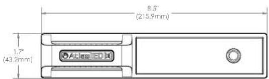
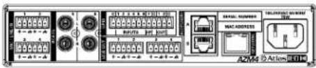
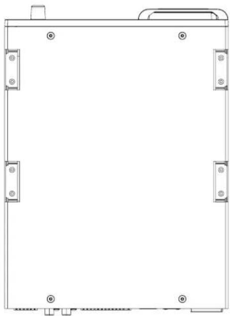
natural_image
Pure technical line drawing of a rectangular enclosure or enclosure frame with mounting holes and no text or symbols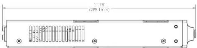

Atlas IED
1601 JACK MCKAY BLVD.
ENNIS, TEXAS 75119 U.S.A.
TELEPHONE: (800) 876-3333
SUPPORT@ATLASIED.COM
AtlasIED.com
Atmosphere
User Manual
Dimensional Drawings
AZM8


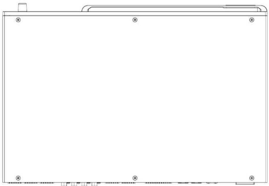
natural_image
Empty rectangular frame with corner markers and a small bracket at the top (no text or symbols)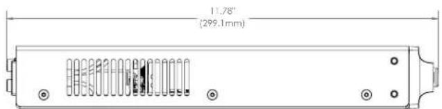
Atmosphere
User Manual
Dimensional Drawings
C-V, C-ZSV, A-RCA, A-BT, and X-ANS share the same dimensions
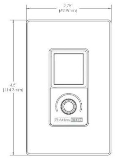
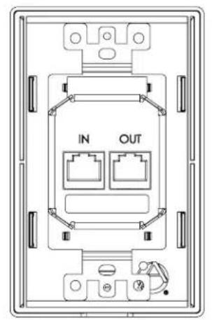
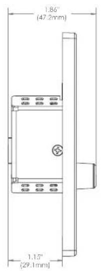
↑
A-XLR
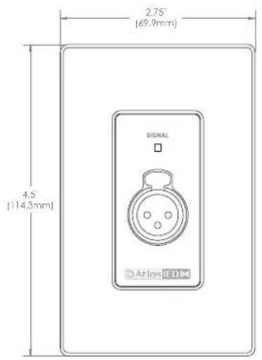
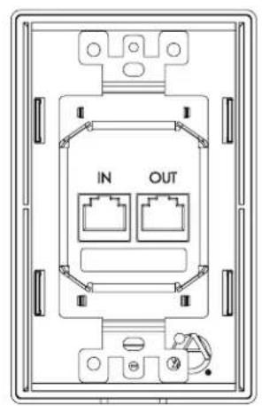
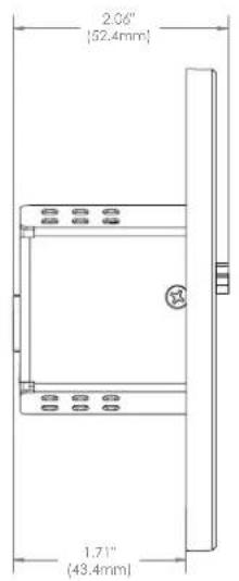
Atmosphere
User Manual
Regulatory Information:
Models: AZM4 / AZM8 / A-BT
United States:
(AZM4 / AZM8) Contains Transmitter Module FCC ID: 2ADHKATWILC1000U.
(A-BT) Contains FCC ID: WAP3026
These devices comply with Part 15 of the FCC Rules, and the requirements for modular transmitter approval as detailed in FCC public Notice DA00-1407. Operation is subject to the following two conditions: (1) this device may not cause harmful interference, and (2) this device must accept any interference received, including interference that may cause undesired operation.
This equipment has been tested and found to comply with the limits for a Class B, (AZM4 & A-BT), and Class A, (AZM8), digital device, pursuant to part 15 of the FCC Rules. These limits are designed to provide reasonable protection against harmful interference in a residential installation. This equipment generates, uses and can radiate radio frequency energy, and if not installed and used in accordance with the instructions, may cause harmful interference to radio communications. However, there is no guarantee interference will not occur in a particular installation. If this equipment does cause harmful interference to radio or television reception, which can be determined by turning the equipment off and on, the user is encouraged to try to correct the interference by one or more of the following measures:
• Reorient or relocate the receiving antenna
- Increase the separation between the equipment and receiver
- Connect the equipment into an outlet on a circuit different from that to which the receiver is connected
- Consult the dealer or an experienced radio/TV technician for help
FCC Radiation Exposure Statement:
This equipment complies with FCC radiation exposure limits set forth for an uncontrolled environment. This equipment should be installed and operated with the following minimum distance between the radiator and your body.
(AZM4 / AZM8) 6.5 cm (2.5")
(A-BT) 10mm (.4")
Canada:
(AZM4 / AZM8) Contains IC: 20266-ATWILC1000
(A-BT) Contains IC: 7922A-3026
This device complies with Industry Canada license exempt RSS standard(s). Operation is subject to the following two conditions: (1) This device may not cause interference, and (2) This device must accept any interference, including interference that may cause undesired operation of the device.
Guidelines on Transmitter Antenna for License Exempt Radio Apparatus:
Under Industry Canada regulations, this radio transmitter may only operate using an antenna of a type and maximum (or lesser) gain approved for the transmitter by Industry Canada. To reduce potential radio interference to other users, the antenna type and its gain should be so chosen that the equivalent isotropically radiated power (e.i.r.p.) is not more than that necessary for successful communication.
ISED RADIATION EXPOSURE STATEMENT FOR CANADA
This equipment complies with ISED radiation exposure limits set forth for an uncontrolled environment. This equipment should be installed and operated with a minimum distance between the radiator and your body.
The AZM4 & A-BT complies with technical specifications required under EN 300 328, EN 301 489, EN55032, EN55035 EN 62368 and EN 60950.
China:
(AZM4 / AZM8) This device contains SRRC approved Radio module CMIIT ID: 2018DJ1313
(A-BT) This device contains SRRC approved Radio module CMIIT ID: 2018DJ5733
Other Accessories:
Models: X-ANS / C-ZSV / C-V / A-RCA / A-XLR
United States:
These devices comply with Part 15 of the FCC Rules. Operation is subject to the following two conditions: (1) this device may not cause harmful interference, and (2) this device must accept any interference received, including interference that may cause undesired operation.
This equipment has been tested and found to comply with the limits for a Class A digital device, pursuant to part 15 of the FCC Rules. These limits are designed to provide reasonable protection against harmful interference when the equipment is operated in a commercial environment. This equipment generates, uses, and can radiate radio frequency energy and, if not installed and used in accordance with the instruction manual, may cause harmful interference to radio communications. Operation of this equipment in a residential area is likely to cause harmful interference in which case the user will be required to correct the interference at his own expense.
Canada:
ICES-003 (A) / NMB-003 (A)
CE Statement:
These devices comply with technical specifications required under EN 55024, EN 55032, EN55035, EN55103-2 EN 62368 and EN 60950.
Notice: Changes or modifications not expressly approved by the party responsible for compliance could void the user's authority to operate the equipment.

Atlas IED
1601 JACK MCKAY BLVD.
ENNIS, TEXAS 75119 U.S.A.
TELEPHONE: (800) 876-3333
SUPPORT@ATLASIED.COM
AtlasIED.com
Atmosphere
User Manual
Limited Warranty
All products manufactured by AtlasLED are warranted to the original dealer/installer, industrial or commercial purchaser to be free from defects in material and workmanship and to be in compliance with our published specifications, if any. This warranty shall extend from the date of purchase for a period of three years on all AtlasLED products, including SOUNDOLIER brand, and ATLAS SOUND brand products except as follows: one year on electronics and control systems; one year on replacement parts; and one year on Musician Series stands and related accessories. Additionally, fuses and lamps carry no warranty. AtlasLED will solely at its discretion, replace at no charge or repair free of charge defective parts or products when the product has been applied and used in accordance with our published operation and installation instructions. We will not be responsible for defects caused by improper storage, misuse (including failure to provide reasonable and necessary maintenance), accident, abnormal atmospheres, water immersion, lightning discharge, or malfunctions when products have been modified or operated in excess of rated power, altered, serviced or installed in other than a workman like manner. The original sales invoice should be retained as evidence of purchase under the terms of this warranty. All warranty returns must comply with our returns policy set forth below. When products returned to AtlasLED do not qualify for repair or replacement under our warranty, repairs may be performed at prevailing costs for material and labor unless there is included with the returned product(s) a written request for an estimate of repair costs before any nonwarranty work is performed. In the event of replacement or upon completion of repairs, return shipment will be made with the transportation charges collect.
EXCEPT TO THE EXTENT THAT APPLICABLE LAW PREVENTS THE LIMITATION OF CONSEQUENTIAL DAMAGES FOR PERSONAL INJURY, ATLASIED SHALL NOT BE LIABLE IN TORT OR CONTRACT FOR ANY DIRECT, CONSEQUENTIAL OR INCIDENTAL LOSS OR DAMAGE ARISING OUT OF THE INSTALLATION, USE OR INABILITY TO USE THE PRODUCTS. THE ABOVE WARRANTY IS IN LIEU OF ALL OTHER WARRANTIES INCLUDING BUT NOT LIMITED TO WARRANTIES OF MERCHANTABILITY AND FITNESS FOR A PARTICULAR PURPOSE.
AtlasIED does not assume, or does it authorize any other person to assume or extend on its behalf, any other warranty, obligation, or liability. This warranty gives you specific legal rights and you may have other rights which vary from state to state.
Online Warranty Claim Processes
1) Warranty submissions are accepted at: https://www.atlasied.com/warranty_statement where the type of return-Warranty Claim or Stock Return can be selected.
Submit a Warranty Claim
Submit a Return Request
2) If already logged-in, navigate to this page by selecting "Support" and then "Warranty & Returns" from the top menu. If you aren't logged into the site, once the type of return is selected, you will be prompted to enter your login credentials. If you do not have a login, register on the site.
3) In order to file a Warranty Claim or Return, you will need:
A) A copy of the invoice/receipt of the purchased item
B) Date of purchase
C) The product name or SKU
D) The serial number for the item (if no serial number exists, enter N/A)
E) A brief description of the fault for the claim (for warranty claims)
4) Once all required fields are completed, select the "Submit Button".
A) You will receive 2 emails:
- One with a confirmation of the submission
- One with a case# for your reference should you need to contact us.
Please allow 2-3 business days for a response with a Return Authorization (RA) number and further instructions.
- Atmosphere™ Next-Gen Expandable Zone DSP Controller
- Atmosphere
- Table of Contents
- User Manual
- Important Safety Instructions
- Introduction
- Inputs and Outputs
- Flexible Assortment of Smart Accessories with Self-Heal
- Configurable Mobile Device Control
- Comprehensive Web User Interface with Dynamic Dashboard
- Stereo and Subwoofer Support
- Room Combine / Zone Grouping
- Bell Scheduler
- Actions and Triggers - Routines, Scenes
- Expanded Mixing Capabilities
- Key Features
- Applications
- Rack Installation Guide
- Hardware Overview
- AZM4 and AZM8 Front Panel
- WiFi Enable
- Display
- Navigation Control & Factory Reset
- Light Bar System "State" Indicator
- Balanced Mic/Line Inputs
- Summed Line Inputs
- Balanced Line Outputs
- GPIO (General Purpose Input Output Ports)
- Accessory Ports
- Network
- AC Power
- Connections
- Cabling
- Network Connection Overview
- Connecting Devices to the AZM for Configuration
- Logging in to the AZM:
- Software Overview (in order of toolbar, left to right)
- Dashboard
- Features
- Sources
- Source Settings-General
- Stereo Sources
- Sources - DSP
- De-Esser
- Example method of setting a De-Esser:
- • Band 1 types include:
- • Band 2 & 3 types include:
- - Band 4 types include:
- Audio Wall Plate Accessories
- A-XLR
- A-RCA
- A-BT
- Audio Wall Plate Accessories that begin with an "A", denoting that they are audio inputs, include:
- Add Source for A-XLR on Input Source Page
- How to pair with the A-BT Wall Plate
- Mixes
- Zones
- Zone - Ambient Noise Compensation - ANC
- Ambient Noise Sensor Placement
- Zone-Groups Overview
- Message Player Overview
- Messages
- Priority
- GPIO Overview
- GPIO - Inputs
- Setting Up a GPIO to Recall a Scene and/or Play a Message
- Scenes Overview
- Routines Overview
- Accessories Overview
- Virtual Wall Controller Setup - Schedule
- Plug and Play Accessories Connection Rules
- Scheduler
- Scheduler Calendar
- Steps to add a bell schedule
- - Zones popup settings for each bell
- Calendar - Set Up Bells
- Calendar – Schedule Exceptions
- Connection Diagram
- Block Diagram
- Settings Page Overview
- Configurations
- Network
- Firmware
- Device Settings
- Clock
- Event Log
- User Account
- User Account Setup
- Project Settings
- Theme
- Dimensional Drawings
- Regulatory Information:
- United States:
- FCC Radiation Exposure Statement:
- Canada:
- Guidelines on Transmitter Antenna for License Exempt Radio Apparatus:
- ISED RADIATION EXPOSURE STATEMENT FOR CANADA
- China:
- Other Accessories:
- CE Statement:
- Limited Warranty
- Online Warranty Claim Processes
- Submit a Warranty Claim
- Submit a Return Request
Brand : Atlas Sound
Model : AZM4
Category : Microphone