
DCE-1 - Électronique audiovisuelle AMX - Free user manual and instructions
Find the device manual for free DCE-1 AMX in PDF.


| Product Type | In-Line Controller with CEC control, EDID emulation, and audio extraction |
| Brand | AMX |
| Model | DCE-1 |
| Dimensions (H x W x D) | 1 in (2.5 cm) x 4.7 in (12 cm) x 3 in (8 cm) |
| Weight | Approx. 0.66 lb (0.30 kg) |
| Power Supply | External 12 VDC, 2A max; Input 100-240 VAC, 50/60 Hz |
| Power Consumption | 3.6 W |
| HDMI Support | 4K60 4:4:4, HDCP 1.4 and 2.2 |
| EDID Management | Copy from output or select from 15 presets via rotary switch |
| Audio De-embedding | Digital S/PDIF (coaxial) and analog stereo (3.5mm phoenix) |
| Display Control | Automatic via CEC, RS232, or IR; pre-loadable RS232 commands |
| Relay Control | Two relays for screen/projector control |
| RS232 Port | Bidirectional, baud rate 1200-115200, configurable |
| Input Cable Equalization | Yes, for signal regeneration |
| Operating Temperature | 32°F to 122°F (0°C to 50°C) |
| Storage Temperature | 14°F to 140°F (-10°C to 60°C) |
| Regulatory Approvals | CE, FCC, NRTL, RoHS, WEEE |
| Mounting Options | V-Style surface mount brackets included |
| Included Accessories | 12V/1A power adapter (US/EU/UK plugs), 4x phoenix connectors, 2x mounting ears with screws |
| Maintenance | Clean with dry cloth only; no user-serviceable parts |
| Safety Features | ESD protection, overvoltage protection, polarized plug, grounding |
| Warranty | See AMX Warranty and Return Policy at www.amx.com |
Frequently Asked Questions - DCE-1 AMX
CPW1PSONONT to store power-on strings. Then connect the display to the DCE-1 RS232 port for automatic control.~UPG! command. Refer to the API command list for upgrade instructions.User questions about DCE-1 AMX
0 question about this device. Answer the ones you know or ask your own.
Ask a new question about this device
Download the instructions for your Électronique audiovisuelle in PDF format for free! Find your manual DCE-1 - AMX and take your electronic device back in hand. On this page are published all the documents necessary for the use of your device. DCE-1 by AMX.
USER MANUAL DCE-1 AMX
IMPORTANT SAFETY INSTRUCTIONS
-
READ these instructions.
-
KEEP these instructions.
-
HEED all warnings.
-
FOLLOW all instructions.
-
DO NOT use this apparatus near water.
-
CLEAN ONLY with dry cloth.
-
DO NOT block any ventilation openings. Install in accordance with the manufacturer's instructions.
-
DO NOT install near any heat sources such as radiators, heat registers, stoves, or other apparatus (including amplifiers) that produce heat.
-
DO NOT defeat the safety purpose of the polarized or grounding type plug. A polarized plug has two blades with one wider than the other. A grounding type plug has two blades and a third grounding prong. The wider blade or the third prong are provided for your safety. If the provided plug does not fit into your outlet, consult an electrician for replacement of the obsolete outlet.
-
PROTECT the power cord from being walked on or pinched, particularly at plugs, convenience receptacles, and the point where they exit from the apparatus.
-
ONLY USE attachments/accessories specified by the manufacturer.
-
USE ONLY with a cart, stand, tripod, bracket, or table specified by the manufacturer, or sold with the apparatus. When a cart is used, use caution when moving the cart/apparatus combination to avoid injury from tip-over.

- UNPLUG this apparatus during lightning storms or when unused for long periods of time.
- REFER all servicing to qualified service personnel. Servicing is required when the apparatus has been damaged in any way, such as power-supply cord or plug is damaged, liquid has been spilled or objects have fallen into the apparatus, the apparatus has been exposed to rain or moisture, does not operate normally, or has been dropped.
- DO NOT expose this apparatus to dripping or splashing and ensure that no objects filled with liquids, such as vases, are placed on the apparatus.
- To completely disconnect this apparatus from the AC Mains, disconnect the power supply cord plug from the AC receptacle.
- Where the mains plug or an appliance coupler is used as the disconnect device, the disconnect device shall remain readily operable.
- DO NOT overload wall outlets or extension cords beyond their rated capacity as this can cause electric shock or fire.

The exclamation point, within an equilateral triangle, is intended to alert the user to the presence of important operating and maintenance (servicing) instructions in the literature accompanying the product.

The lightning flash with arrowhead symbol within an equilateral triangle is intended to alert the user to the presence of uninsulated "dangerous voltage" within the product's enclosure that may be of sufficient magnitude to constitute a risk of electrical shock to persons.

ESD Warning: The icon to the left indicates text regarding potential danger associated with the discharge of static electricity from an outside source (such as human hands) into an integrated circuit, often resulting in damage to the circuit.
WARNING: To reduce the risk of fire or electrical shock, do not expose this apparatus to rain or moisture.
WARNING: No naked flame sources - such as candles - should be placed on the product.
WARNING: Equipment shall be connected to a MAINS socket outlet with a protective earthing connection.
COPYRIGHT NOTICE
AMX© 2018, all rights reserved. No part of this publication may be reproduced, stored in a retrieval system, or transmitted, in any form or by any means, electronic, mechanical, photocopying, recording, or otherwise, without the prior written permission of AMX. Copyright protection claimed extends to AMX hardware and software and includes all forms and matters copyrightable material and information now allowed by statutory or judicial law or herein after granted, including without limitation, material generated from the software programs which are displayed on the screen such as icons, screen display looks, etc. Reproduction or disassembly of embodied computer programs or algorithms is expressly prohibited.
LIABILITY NOTICE
No patent liability is assumed with respect to the use of information contained herein. While every precaution has been taken in the preparation of this publication, AMX assumes no responsibility for error or omissions. No liability is assumed for damages resulting from the use of the information contained herein. Further, this publication and features described herein are subject to change without notice.
AMX WARRANTY AND RETURN POLICY
The AMX Warranty and Return Policy and related documents can be viewed/downloaded at www.amx.com.
ESD WARNING
 | To avoid ESD (Electrostatic Discharge) damage to sensitive components, make sure you are properly grounded before touching any internal materials.When working with any equipment manufactured with electronic devices, proper ESD grounding procedures must be followed to make sure people, products, and tools are as free of static charges as possible. Grounding straps, conductive smocks, and conductive work mats are specifically designed for this purpose. These items should not be manufactured locally, since they are generally composed of highly resistive conductive materials to safely drain static discharges, without increasing an electrocution risk in the event of an accident.Anyone performing field maintenance on AMX equipment should use an appropriate ESD field service kit complete with at least a dissipative work mat with a ground cord and a UL listed adjustable wrist strap with another ground cord. |



WARNING: Do Not Open! Risk of Electrical Shock. Voltages in this equipment are hazardous to life. No user-serviceable parts inside. Refer all servicing to qualified service personnel.
Place the equipment near a main power supply outlet and make sure that you can easily access the power breaker switch.
WARNING: This product is intended to be operated ONLY from the voltages listed on the back panel or the recommended, or included, power supply of the product. Operation from other voltages other than those indicated may cause irreversible damage to the product and void the products warranty. The use of AC Plug Adapters is cautioned because it can allow the product to be plugged into voltages in which the product was not designed to operate. If the product is equipped with a detachable power cord, use only the type provided with your product or by your local distributor and/or retailer. If you are unsure of the correct operational voltage, please contact your local distributor and/or retailer.
WARNING: Avoid exposure to extreme heat or cold.
FCC AND CANADA EMC COMPLIANCE INFORMATION:
This equipment has been tested and found to comply with the limits for a Class B digital device, pursuant to Part 15 of the FCC Rules. These limits are designed to provide reasonable protection against harmful interference in a residential installation. This equipment generates uses and can radiate radio frequency energy and, if not installed and used in accordance with the instructions, may cause harmful interference to radio communications. However, there is no guarantee that interference will not occur in a particular installation. If this equipment does cause harmful interference to radio or television reception, which can be determined by turning the equipment off and on, the user is encouraged to try to correct the interference by one or more of the following measures:
• Reorient or relocate the receiving antenna.
- Increase the separation between the equipment and receiver.
- Connect the equipment into an outlet on a circuit different from that to which the receiver is connected.
- Consult the dealer or an experienced radio/TV technician for help.
Changes or modifications not expressly approved by the party responsible for compliance could void the user's authority to operate the equipment.
EU COMPLIANCE INFORMATION:
Eligible to bear the CE mark; Conforms to European Union Low Voltage Directive 2014/35/EU; European Union EMC Directive 2004/108/EC; European Union Restriction of Hazardous Substances Recast (RoHS2) Directive 2011/65/EU; European Union WEEE (recast) Directive 2012/19/EU; European Union Eco-Design Directive 2009/125/EC; European Union Registration, Evaluation, Authorization and Restriction of Chemicals (REACH) Directive 2006/121/EC
You may obtain a free copy of the Declaration of Conformity by visiting http://www.amx.com/techcenter/certifications.asp.
WEEE NOTICE:
 | This appliance is labeled in accordance with European Directive 2012/19/EU concerning waste of electrical and electronic equipment (WEEE). This label indicates that this product should not be disposed of with household waste. It should be deposited at an appropriate facility to enable recovery and recycling. |
Table of Contents
Safety Instructions 2
ESD Warning.... 3
Table of Contents 4
Overview....5
Features 5
Key Benefits 5
Package Contents.... 5
Specifications.... 6
Front Panel Description 9
Rear Panel Description.... 10
Installation.... 11
Wiring 11
EDID Management 13
RS232 Control 14
DCE-1 Control 14
Display Control.... 15
Troubleshooting.... 15
API Command List Instructions.... 16
Overview
The AMX DCE-1 In-Line Controller combines CEC control, EDID emulation and audio extraction in a single, cost-effective device.
Reliable EDID Emulation
The DCE-1 provides EDID emulation for resolutions up to 4K60 4:4:4, and includes HDCP 2.2 support, offering compatibility with the latest displays and source devices. The integrator can either copy the EDID from the output or select from one of 15 preprogrammed EDIDs. The controller provides a fixed EDID to the source device to ensure it reliably outputs video in the correct resolution for the display.
De-embed Capable with Simplified Display Control
The DCE-1 also offers audio de-embed capabilities, with digital SPDIF and analog output options. To simplify display control, the DCE-1 also offers the ability to turn the display on and off using CEC, or RS232 strings whenever a source device is connected or disconnected.
Common Applications
Ideal for a variety applications requiring in-line EDID emulation, audio extraction, or simple display control.
Features
Extended Display Identification Data (EDID) – Provides a fixed EDID to the source to ensure that it always reliably outputs video
4K60 4:4:4 and HDCP 2.2 Support – Support the latest source and display devices. Experience pixel-for-pixel video reproduction of 4K@60Hz source video with full 4:4:4 color space
Signal-Based Display Control – Use CEC, RS232, or IR to automatically turn displays on/off in response to a change in the input signal. Pre-load and store RS232 commands for display device
Audio De-embed Capabilities – Remove audio from line to be used in signal processing, amplification, and more, including Digital Coaxial and Analog Stereo
Rotary Switch for EDID Management with 15 EDID presets
Key Benefits
Automatic CEC and RS232 - Commands to power on or standby display device by detecting input signal status
Built-In Relay control - Automatically trigger devices based on video presence
Input Cable Equalization - For signal regeneration and compensation
Package Contents
- 1x DCE-1
• 1x DC12V/1A Power Adapter(with UK, US and Europlugs)
• 4x Phoenix Male Connector (3.5 mm, 3 Pins)
• 2x Mounting Brackets (with screws)
Specifications
| DCE-1 Specifications | |
| General | |
| Dimensions 3 in (8cm) | depth 4.7 in (12cm) width 1 In (2.5cm) height |
| Weight Approx. 0.66 lb | (0.30 kg) |
| Shipping Weight TBD | |
| Mounting Options Includes V-Style surface mount brackets | |
| Approvals: Regulatory Compliance | CE, FCC, NRTL, RoHS, WEEE |
| Airflow Convection (openings on sides) | |
| Included Accessories 4x 3P-3.5MM Phoenix Connectors 1x 12V/1A Power Adapter 1x US exchangeable adapter 1x EU exchangeable adapter 1x UK exchangeable adapter 2x mounting ear 4x M2.5 screw (for mounting ears) | |
| Power Supply | |
| External, Included 12 VDC 2A Max Output; 100-240V 50/60Hz AC Input | |
| Active Power Requirements | |
| Voltage, DC (Typical) 12 VDC | |
| Power Consumption 3.6w | |
| Power Connector Screw down locking power connector | |
| Environmental | |
| Temperature (Operating) | 32°F to 122°F (0°C to 50°C) |
| Temperature (Storage) | 14° to 140°F (-10° to 60°C) |
| Humidity (Operating) 10% to 90% RH (non-condensing) | |
| Humidity (Storage) 10% to 90% RH (non-condensing) | |
| Thermal Dissipation 12 BTU/hr | |
| Front Connectors | |
| DC Power Screw Down Locking Power Connector | |
| HDMI Input (1) HDMI Type A Female Connector | |
| Digital Audio Output (1) RCA S/PDIF | |
| Analog Stereo Output | (1) 3 Position 3.5mm pluggable Phoenix Terminal Block |
| Rear Connectors | |
| Relay Control | (2) 3 Position 3.5mm Pluggable Phoenix Terminal Blocks |
| HDMI Output | (1) HDMI Type A Female Connector |
| Serial | 3 Position 3.5mm Pluggable Phoenix Terminal Block Bidirectional RS-232 Standard NetLinx Baud rate 1200-115k Parity support Odd/Even/None |
| Controls and Indicators | |
| Power Indicator | Green LED, Solid ON when power is applied (Front) |
| EDID Selection | Rotary Dial - 16 Position |
Specifications
| DCE-1 Specifications (cont.) | |
| HDMI | |
| Compatible Formats HDMI , HDCP | |
| Signal Type Support HDMI, DisplayPort++ (input only with HDMI cable adapter) | |
| Output Signal Type HDMI, HDCP | |
| Output Connector HDMI Type A Female | |
| Input Video Level .5 - 1.2 V p-p | |
| Data Rate (Max) 18 Gbp | |
| Pixel Clock (Max) Up to 600 Mhz | |
| Resolution Support VESA | |
| 800x600 @ 60 Hz1024x768 @ 60 Hz1280x768 @ 60 Hz1280x800 @ 60 Hz1280x960 @ 60 Hz1280x1024 @ 60 Hz1360x768 @ 60 Hz1366x768 @ 60 Hz1440x900 @ 60 Hz1600x900 @ 60 Hz1600x1200 @ 60 Hz1680x1050 @ 60 Hz1920x1200 @ 60 Hz2048x1152 @ 60 Hz3840x2160 @ 24 Hz, 25Hz, 30 Hz, 60 Hz4096x2160 @ 24 Hz, 25Hz, 30 Hz, 60 HzSMPT720x480 @ 59.94 Hz, 60 Hz720x576 p @ 50 Hz1280x720 p @ 50 Hz, 59.95 Hz, 60 Hz1920x1080 p @ 50 Hz, 59.94 Hz, 60 HzEstablished Timing1280 x 1024 @ 75 Hz1152 x 870 @ 75 Hz1024 x 768 @ 60 Hz, 70 Hz, 75 Hz, 87 Hz832 x 624 @ 75 Hz800 x 600 @ 56 Hz, 60 Hz, 72 Hz, 75 Hz720 x 400 @ 70 Hz, 88 Hz640 x 480 @ 60 Hz, 67 Hz, 72 Hz, 75 HzCEA Information Code (VIC) Formats:VIC = 1, 640 x 480 p 59.94/60 Hz 4:3VIC = 2, 720 x 480 p 59.94/60 Hz 4:3VIC = 3, 720 x 480 p 59.94/60 Hz 16:9VIC = 4, 1280 x 720 p 59.94/60 Hz 16:9VIC = 5, 1920 x 1080 i 59.94/60 Hz 16:9VIC = 6, 720(1440) x 480 i 59.94/60 Hz 4:3VIC = 7, 720(1440) x 480 i 59.94/60 Hz 16:9VIC = 14, 1440 x 480 p 59.94/60 Hz 4:3VIC = 15, 1440 x 480 p 59.94/60 Hz 16:9VIC = 16, 1920 x 1080 p 59.94/60 Hz 16:9VIC = 17, 720 x 576 p 50 Hz 4:3VIC = 18, 720 x 576 p 50 Hz 16:9VIC = 19, 1280 x 720 p 50 Hz 16:9VIC = 20, 1920 x 1080 i 50 Hz 16:9VIC = 21, 720(1440) x 576 i 50 Hz 4:3VIC = 22, 720(1440) x 576 i 50 Hz 16:9VIC = 29, 1440 x 576 p 50 Hz 4:3VIC = 30, 1440 x 576 p 50 Hz 16:9 VIC = 30, 1440 x 576 p 50 Hz 16:9VIC = 31, 1920 x 1080 p 50 Hz 16:9VIC = 32, 1920 x 1080 p 23.97/24 Hz 16:9VIC = 33, 1920 x 1080 p 25 Hz 16:9VIC = 34, 1920 x 1080 p 29.97/30 Hz 16:9VIC = 39, 1920 x 1080 i 50 Hz 16:9VIC = 41, 1280 x 720 p 100 Hz 16:9VIC = 42, 720 x 576 p 100 Hz 4:3VIC = 43, 720 x 576 p 100 Hz 16:9VIC = 44, 720(1440) x 576 i 100 Hz 4:3VIC = 45, 720(1440) x 576 i 100 Hz 16:9 | |
Specifications
| DCE-1 Specifications (cont.) | |
| HDMI (cont.) | |
| 4K Format Support 384 | 0x2160p@24/25/30/60 Hz, 4:4:44096x2160p@24/25/30/60 Hz, 4:4:43840x2160p@50/60 Hz, 4:2:04096x2160p@50/60 Hz, 4:2:0 |
| Audio Format Support | Dolby TrueHD, Dolby Digital, DTS-HD Master Audio, DTS, 2 CH L-PCM, 6 CH L-PCM, 8 CH L-PCM Dolby Digital and DTS support up to 48kHz, 5.1 channel |
| Digital Audio S/PDIF Output | Supported when HDMI embedded audio is up to PCM 5.1, Dolby Digital, DTS 5.1 |
| Analog Stereo Output | Supported when audio is 2 Channel PCM |
| HDCP Support Yes HDCP | 1.4, 2.2 |
| CEC Support Yes, Auto | or Manual |
Front Panel Description

| No. | Name Description | |
| 1 | RELAY 1-2 | Connect to the projector screen for Relay control (turn on or off the projector screen) when DCE-1 detects input signal status change. |
| 2 | HDMI OUT Connect to | an HDMI display. |
| 3 | RS-232 Connect to a PC | or RS232-enabled display to control the DCE-1 or the display through RS232 serial commands. |
Rear Panel Description

| No. | Name Description | |
| 1 | DC 12V 12V DC power | input, threaded port for standard or locking connection. |
| 2 | POWER LED On: The device is powered on.Off: The device is powered off. | |
| 3 | HDMI IN Connect to an HDMI source. | |
| 4 | EDID For EDID Management | |
| 5 | S/PDIF OUT | HDMI audio de-embedded out with Digital Coaxial, connect to amplifier or other appropriate audio deviceNote: This port supports multi-channel audio up to PCM 5.1, Dolby Digital and DTS 5.1. |
| 6 | AUDIO OUT | HDMI audio de-embedded out with Analog Stereo, connect to amplifier or other appropriate audio deviceNote: This port supports stereo audio only. |
Installation
Warning: Before installation, ensure the device is disconnected from the power source.
- Position and install the mounting brackets with the four mounting screws provided.
- Mount and secure the device to a surface or a suitable location with the mounting screws.

natural_image
Technical line drawing of a mechanical bracket with mounting holes and a dashed line indicating assembly (no text or symbols)Attach the brackets provided to side panels of the device
Wiring
Warning: Before wiring, disconnect the power from all devices. Connect and disconnect the cables with care
- Connect HDMI IN Connect an HDMI source (PC, Blu-ray player, etc.) device to HDMI IN of the DCE-1 using a high-quality HDMI cable
- Connect HDMI OUT Connect an HDMI display device (LED Display, Projector, etc.) to HDMI OUT of the DCE-1
- Connect S/PDIF OUT and AUDIO OUT Connect audio devices (Amplifier, etc.) to the S/PDIF OUT and AUDIO OUT port of the DCE-1
- Connect RS232-enabled display control Connect an RS232-enabled display (Projector, etc.) to the RS232 port of the DCE-1 to control the display through pre-loaded RS232 commands.
- Connect for relay control Connect the projection screen to Relay 1 and Relay 2 of the DCE-1 to turn ON or OFF the screen through pre-loaded RS232 commands.
- Connect the included 12V power adapter to the DCE-1. Power ON all attached devices.
Wiring

flowchart
graph TD
    A["PC"] -->|HDMI IN AUDIO OUTS/PDIF OUT| B["In-ceiling Speaker Amplifier"]
    B -->|L/R| C["AMX"]
    C -->|RELAY Control| D["Projection Screen Projector"]
    C -->|OUT| E["RS232 ControlHDMI"]
    style A fill:#f9f,stroke:#333
    style B fill:#ccf,stroke:#333
    style C fill:#cfc,stroke:#333
    style D fill:#fcc,stroke:#333
    style E fill:#ffc,stroke:#333
EDID Management
EDID (Extended Display Identification Data) is a data structure provided by a digital display to describe its capabilities to a video source.
The DCE-1 features multiple EDID presets which can be performed using the EDID rotary switch on the rear panel. By default, the EDID switch is set in position 0. Should any compatibility issues occur, use the following table for the EDID setting:
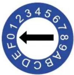
| Position Description | |
| 0 (default) Copy EDID from HDMI OUT | |
| 1 Set 3840x2160@60Hz | 2CH as input EDID |
| 2 Set 3840x2160@30Hz | 2CH as input EDID |
| 3 Set 1920x1080@60Hz | 2CH as input EDID |
| 4 Set 1280x720@60Hz | 2CH as input EDID |
| 5 Set 1920x1200@60Hz | 2CH as input EDID |
| 6 Set 1680x1050@60Hz | 2CH as input EDID |
| 7 Set 1600x1200@60Hz | 2CH as input EDID |
| 8 Set 1600x900@60Hz | 2CH as input EDID |
| 9 Set 1440x900@60Hz | 2CH as input EDID |
| A Set 1400x1050@60Hz | 2CH as input EDID |
| B Set 1360x768@60Hz | 2CH as input EDID |
| C Set 1280x1024@60Hz | 2CHas input EDID |
| D Set 1280x960@60Hz | 2CH as input EDID |
| E Set1280x768@60Hz | 2CH as input EDID |
| F Set 1024x768@60Hz | 2CH as input EDID |
Note:
- If EDID copy fails, 1920x1080@60Hz with stereo audio will be set as the Input EDID.
- For the EDID settings to take effect, the DCE-1 must be re-booted.
RS232 Control
The RS232 port allows control of the DCE-1 or connected display through RS232 commands. The following diagram shows the RS232 pinout. Connect with the provide Phoenix Connector.
RS232 Port Connected RS232 Device Pins
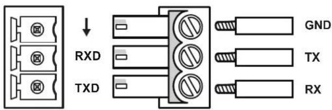
DCE-1 Control
Connect a control PC to the DCE-1 via a USB-UART cable, and run a terminal emulation program on your PC to configure the connection parameters correctly. The baud rate for the DCE-1 is 9600. This allows execution of RS232 commands through the software. For more information, refer to the API Command List Instructions at the end of this document.

Example:
Command:
CUB1T
Response:
CUB1T
Explanation:
UB#: # = {1-6}
- 9600
- 14400
- 19200
- 38400
- 56000
- 57600
This command is used to set baudrate for the serial portto 9600.
Display Control
To control a display (Projector, etc.) through pre-loaded RS232 commands, configure the RS232 port of the DCE-1 according to the display parameters.
- Connect a PC to the DCE-1 according to section "Control the DCE-1".
- Configure RS232 parameters of the DCE-1 with the serial port software according to the display parameters. For example: set the correct baud rate, preload Power-ON and Power-OFF commands in string/hex (refer to the document "API Command Set_DCE-1).
- Disconnect the PC from the DCE-1, and connect the display according to the diagram on page 6. The DCE-1 can automatically execute RS232 commands to Power ON or OFF the connected projector and projection screen when an input signal change is detected.
Troubleshooting
Power: Ensure all devices are powered on.
Indicator: Ensure all LED indicators of the DCE-1 are normal according to the user manual.
Devices: Ensure picture can be shown normally when directly connecting a source to a display device.
Cable: Plug the HDMI cable in and out or connect a different HDMI cable. Ensure the specific cable length is within the available transmission range according to the Specifications Section.
EDID: There are multiple EDID presets depending on the EDID rotary switch setting. Please refer to the EDID Management Section to ensure the display works properly.
Compatibility: Test other source and display devices to determine correct compatibility.
API Command List Instructions
General Rules for Using BCS Commands
- Command strings typically are not case-sensitive.
- All command strings must end with the Take command "T" which tells the system to execute the command.
- “O” is the letter O, not the number zero (0).
- Entering "X" at any point in a command string cancels the command.
- A command cannot be canceled after the "T" has been entered.
- Command strings cannot be edited. If a mistake has been made, enter an "X" and then reenter the command.
- To specify multiple outputs, inputs, levels, or local presets, enter a space “” between each number. Multiple
- inputs are only valid in Disconnect commands.
- To specify a range of outputs, inputs, or local presets, insert a colon ":" between the lowest and highest numbers of the range (not supported if the command is otherwise invalid, e.g., cannot specify a range of inputs in a Change command; the first input only would be routed).
- Colons ":" and spaces " " can be used in the same command string.
- If the level designation "L" is omitted, the command is executed on the default level, which is normally Level 0.
RS232 Default Setting
| Parameters Value | |
| Baud Rate 9600 bps | |
| Data bits 8 bits | |
| Parity None | |
| Stop bits 1 bit | |
| Flow control None |
API Command List Instructions (cont.)
| IDX Function Description Command Example Note | ||||
| 1 Configure UART command in string | Command:CPW#PS#TReturn:CPW#PS#TDescription:PW#: # = {0, 1}0: off1: onPS#: # = {xxxxxxxxxxxxxxxxxxx}// STR is the original command according to device guidelines. | Command:CPW1PSONONTReturn:CPW1PSONONTDescription:Configure “ONON” for the power-on command in string for the display. | ||
| 2 Configure UART command in hex | Command:CPW#PH#TReturn:CPW#PH#TDescription:PW#: # = {0, 1}0: off1: onPH#: # = {hex1, hex2, ..., hex64}// hex1, hex2, ..., hex64 is ASC II string of hex value.For example, string “123”, convert to correct string is “31 32 33”. | Command:CPWOPH123TReturn:CPWOPH123TDescription:Configure “123” for the power-off command in hex for the display. | ||
| 3 Get UART command Command: | SPW#PSTReturn:SPW#PST(xxxx)Description:PW#: # = {0, 1}0: off1: onPST (xxxx): “xxxx” is the original command according to device guidelines. | Command:SPW1PSTReturn:SPW1PST(xxx)Description:Get UART command for display power-on, the result is “xxx”. | ||
| 4 Set UART baud rate Command: | CUB#TReturn:CUB#TDescription:UB#: # = {1~6}1: 96002: 144003: 192004: 384005: 56000 | Command:CUB1TReturn:CUB1TDescription:Set UART baud rate to 9600. | ||
| 5 Set the delay time to execute power off for the sink when no active signal detected | Command:CD#SPTReturn:CD#SPTDescription:CECAUTO_DELAY is short for CEC auto Power Delay Timing.D#: # = {1~30MIN} | Command:CD2SPTReturn:CD2SPTDescription:Set the delay time to 2 minutes. | Default delay time is 2 minutes. | |
| 6 Get CEC power-off delay time | Command:SDSPTReturn:SDSPT(value)Description:value = {1, 2, ..., 30 (MIN)} | Command:SDSPTReturn:SDSPT(2)Description:Get the CEC power-off delay time, the result is 2 minutes. | ||
| IDX Function Description Command Example Note | ||||
| 7 Get all boards firmware version | Command:~VER!Return:~VER!( # ) | Command:~VER!Return:~VER!(mainmcu ver Vx.xclientmcu ver Vx.x)Description:Get all boards firmware version. | ||
| 8 Upgrade module Command: | ~UPG!Return:~UPG! | Command:~UPG!Return:~UPG! | ||
| 9 Reset the device Command: | ~SYSR!Return:~SYSR! | Command:~SYSR!Return:~SYSR! | ||
| 10 Reboot the device Command: | ~APP!Return:~APP! | Command:~APP!Return:~APP! | ||
| 11 Set command ending character | Command:CUE#TReturn:CUE#TParameter:UE#: # = {1~4}1: NULL2: 0X0D3: 0X0A4: 0X0D 0X0A | Command:CUE4TReturn:CUE4TDescription:Set command ending character as “0X0D 0X0A”. | ||
| 12 Set RELAY to LATCH Command: | CRM#TReturn:CRM#TDescription:RM#: # = {1, 2}1: Latch2: Momentary | Command:CRM1TReturn:CRM1TDescription:Set relay to latch mode. | ||
| 13 Get RELAY mode Command: | SRMTReturn:SRMT(value)Description:RM#: # = {1, 2}1: Latch2: Momentary | Command:SRMTReturn:SRMT(1)Description:Get relay mode, the result is Latch. | ||
| IDX Function Description Command Example Note | ||||
| 14 SET RELAY To Momentary | Command:CMD#TReturn:CMD#TDescription:MD#: # = {1 ~10 (seconds)} | Command:CMD2TReturn:CMD2TDescription:Set relay momentary hold time as 2 seconds. | Default setting is 3s. | |
| 15 GET RELAY Momentary Command | SMDTReturn:SMDT(value)Description:value = {1 ~10 (seconds)} | Command:SMDTReturn:SMDT(2)Description:Get relay momentary hold time, the result is 2 seconds. | ||
| 16 Set VP cooling time Command | CVPD#TReturn:CVPD#TDescription:MD#: # = {0~5 (seconds)} | Command:CVPD2TReturn:CVPD2TDescription:Set VP cooling time to 2s. | Default setting is 0s. | |
| 17 Get VP cooling time Command | SVPDTReturn:SVPDT(value)Description:value = {0 ~5 (seconds)} | Command:SVPDTReturn:SVPDT(2)Description:Get VP cooling time, the result is 2s. | ||
| 18 Set the video on mode for the video output port | Command:CVON#TReturn:CVON#TDescription:# = {0 ~1}0: OFF1: ON | Command:CVONOTReturn:CVONOTDescription:Set video on mode as disabled. | ||
| 19 Get the video on mode status for the video output port | Command:SVONTReturn:SVONT(#)Description:# = {0 ~1}0: DISABLE1: ENABLE | Command:SVONTReturn:SVONT(0)Description:Video on mode is disabled. | ||
- IMPORTANT SAFETY INSTRUCTIONS
- COPYRIGHT NOTICE
- LIABILITY NOTICE
- AMX WARRANTY AND RETURN POLICY
- ESD WARNING
- FCC AND CANADA EMC COMPLIANCE INFORMATION:
- EU COMPLIANCE INFORMATION:
- WEEE NOTICE:
- Table of Contents
- Overview
- Reliable EDID Emulation
- De-embed Capable with Simplified Display Control
- Common Applications
- Features
- Key Benefits
- Package Contents
- Specifications
- Front Panel Description
- Rear Panel Description
- Installation
- Wiring
- EDID Management
- Note:
- RS232 Control
- DCE-1 Control
- Display Control
- Troubleshooting
- API Command List Instructions
- General Rules for Using BCS Commands
Brand : AMX
Model : DCE-1
Category : Électronique audiovisuelle