GGSUC908S.1 - Cooker Sôlt - Free user manual and instructions
Find the device manual for free GGSUC908S.1 Sôlt in PDF.


| Product Type | Freestanding Cooker |
| Brand | Sôlt |
| Model | GGSUC908S.1 |
| Dimensions (W × D × H) | 895 × 595 × 858–918 mm |
| Gross / Net Weight | 93.0 kg / 74.2 kg |
| Maximum Power | 2940 W |
| Oven Gross / Usable Capacity | 121 L / 109 L |
| Power Supply | 220–240 V, 50 Hz, 15 A |
| Gas Types Supported | Natural Gas (1.0 kPa) / ULPG (2.75 kPa) |
| Burners (Number & Types) | 5 burners: 1 Triple Crown Wok, 1 Rapid, 2 Semi-rapid, 1 Auxiliary |
| Oven Functions | Light, Defrost, Bake, Fan Assisted Multi-level, Fan Forced, Lower Element, Grill, Full Grill, Fan Assisted Grill |
| Oven Cleaning | Manual cleaning with mild detergent; oven door removable for access; chrome side racks removable |
| Burner Cleaning | Remove caps and flame spreaders; wash in hot soapy water; do not dishwasher |
| Anti-tip Device | Safety stabiliser chain (must be fitted) |
| Safety Features | Flame failure device on gas burners; child lock via knob removal? (not specified); automatic shut-off via timer |
| Warranty | 24 months parts and labour (domestic use) |
| Country of Origin | Designed and distributed by Residentia Group, Australia |
Frequently Asked Questions - GGSUC908S.1 Sôlt
User questions about GGSUC908S.1 Sôlt
0 question about this device. Answer the ones you know or ask your own.
Ask a new question about this device
Download the instructions for your Cooker in PDF format for free! Find your manual GGSUC908S.1 - Sôlt and take your electronic device back in hand. On this page are published all the documents necessary for the use of your device. GGSUC908S.1 by Sôlt.
USER MANUAL GGSUC908S.1 Sôlt
Welcome Congratulations on purchasing your new Freestanding Cooker! The Sôlt brand is proudly distributed within Australia by Residentia Group Pty Ltd.
Residentia Group
Head Office.
165 Barkly Ave
Burnley
Victoria 3121
Australia
ACN.
600 546 656
Online.
residentia.group
Please refer to the warranty card at the rear of this manual for information regarding your product's parts and labour warranty, or visit us online at www.residentia.group
At Residentia Group, we are customer obsessed and our Support Team are there to ensure you get the most out of your appliance. Should you want to learn more about your freestanding cooker features, and importantly taking care of your appliance when cleaning, our Support Team are here to help.
Sôlt
Online.
www.solt.house
Instagram.
/solt.house
Facebook.
/solt.appliances
You can use our online Support Centre at anytime by visiting http://support.residentiagroup.com.au, or you can contact us via calling us on 1300 11 HELP (4357).
It is important that you read through the following use and care manual thoroughly to familiarise yourself with the installation and operation requirements of your appliance to ensure optimum performance.
Again, thank you for choosing an Sôlt appliance and we look forward to being of service to you.
Kind Regards,
The Residentia Team
Contents 2 Welcome
4 General Safety Instructions
7 Your Freestanding Cooker
10 Operating Instructions
13 Cooking Guidelines
14 Cleaning & Maintenance
21 Installation Instructions
30 Electrical Connection
31 Gas Connection
36 Technical Specifications
37 Purchase Details
38 Warranty Information
Customer Care
Sôlt recommends the use of original spare parts. When contacting our customer service team, please ensure that you have the following information at hand (which can be found on your appliances' rating plate).
-ModelNumber
— Serial Number
General Safety Instructions
IMPORTANT SAFETY INSTRUCTIONS
Read carefully and keep for future reference
Read this manual thoroughly before first use, even if you are familiar with this type of product. The safety precautions enclosed herein reduce the risk of fire, electric shock and injury when correctly adhered to. Make sure you understand all instructions and warnings.
Read the instructions in full before installing or using this appliance.
Keep the manual in a safe place for future reference, along with the completed warranty card and purchase receipt. If you sell or transfer ownership of this product, pass on these instructions to the new owner. Always follow basic safety precautions and accident prevention measures when using an electrical appliance, including the following:
WARNING! Installation Electrical Shock Hazard
WARNING: All electrical work associated with the installation of this appliance must be carried out by a licensed electrician.
WARNING: This appliance must be installed by a suitably qualified person in strict accordance with all instructions in this manual.
Disconnect the appliance from the mains electricity supply before carrying out any work or maintenance on it. Failure to follow this advice may result in electrical shock or death.
IMPORTANT INSTALLATION ADVICE
- Adjacent furniture: When having the appliance installed, make sure that the adjacent furniture or housing, and all installation materials, are able to withstand a minimum temperature of 85^ above the ambient room temperature while the oven is in use.
- Certain types of vinyl or laminate kitchen furniture are particularly prone to heat damage or discolouration at temperatures below the guidelines given above. We assume no liability for any damage caused by the appliance being installed in contravention of this temperature limit, or by placing adjacent cabinet materials closer than 4mm near the appliance.
-
Ventilation: Heat, steam and moisture will be created during use of the appliance. Take care to avoid injury and ensure that the room is adequately ventilated. If the appliance is going to be used for prolonged periods of time, additional ventilation may be required. If in doubt about your ventilation requirements, consult your qualified installer.
-
Cables: Do not allow electrical fittings or cables to come into contact with areas on the appliance that gets hot.
- Curtains: Do not install the oven next to curtains or soft furnishings.
- Damaged cord: If the power cord is damaged, it must be replaced by the manufacturer or a qualified service engineer in order to avoid a hazard
- Packaging: Ensure that all packaging elements are kept away from children and disposed of correctly. Most packaging elements can be recycled.
GENERAL USAGE CONDITIONS AND RESTRICTIONS
- Domestic use only: This appliance is designed for indoor domestic use only, it is not intended for commercial use and this will void the warranty.
- Intended purpose: Only use this appliance for its intended purpose, in its intended environment and as described in this manual. Any other use may cause fire, electric shock or injury. It is not intended for commercial, trade or industrial use.
- Before first use: Remove all packaging and protective films. With the oven completely empty, heat the oven for 45 minutes at the maximum temperature; this will burn off any residual manufacturing residues, removing any smoke and smells.
- Follow instructions: Make sure to observe all rules and provisions in this instruction manual. Do not allow anybody who is not familiar with the contents of this manual to operate the appliance.
- Use common sense: These instructions are not intended to cover every possible condition and situation. As with any electrical household appliance, common sense and caution are therefore always recommended when installing, operating and maintaining the oven. Be careful not to come in contact with the internal heating elements.
- Usage restriction: This appliance is not intended for use by persons (including children) with reduced physical, sensory or mental capabilities, or lack of experience and knowledge, unless they have been given supervision or instruction concerning use of the appliance by a person responsible for their safety.
- Supervise children: Young children do not recognise the risks involved when using electrical appliances. Make sure children younger than 8 years of age are kept away from the appliance during use and after use. If it is necessary for younger family members to be in the kitchen, ensure that they are kept under close supervision at all times. Never allow children to play with or climb on the oven or oven door.
- Unattended: Never leave the appliance unattended during use, as this is a fire risk. Oils and fats in roasting dishes may catch fire due to overheating.
- No heater: Do not use the appliance for heating a
room or drying clothes. This appliance must not be used as a space heater.
- No external timer: The appliance is not intended to be operated by means of an external timer or separate remote control system.
- After use: Make sure to switch off the oven after use and before cleaning.
- Damage: Do not use the appliance if any part has been damaged or does not work properly. Only have it repaired by an authorised service centre. Incorrect repair could expose you to the risk of electric shock, fire or injury. Prolonged use of the unit in such conditions could cause fire or electrocution. In case of damage, contact our after sales support centre using the details at the bottom of this page.
- Liability: We assume no liability for any eventual damages caused by misuse of the product or noncompliance with these instructions.
- Do not use when faulty: Do not use the appliance in the event of a technical fault. Any faults must be fixed by an appropriately qualified and authorised person. Contact our after sales support line for advice.
- No storage: Do not store flammable materials in the appliance or near this appliance.
- No Aerosols: Do not spray aerosols in the vicinity of this appliance while it is in operation.
- Cleaning: Clean the oven and cooktop on a regular basis so oils and fats do not accumulate and cause a fire risk. Make sure the appliance is switched off before cleaning. Do not use harsh abrasive cleaners or metal scrapers to clean the oven door glass as this can scratch the surface, which may result in the oven glass shattering. Do not use steam cleaning equipment for cleaning any part of the appliance. When cleaning the appliance, ensure that no part is immersed in water or other liquid.
- Do not remove the plug by pulling on the cable.
OVEN-SPECIFIC SAFETY ADVICE
- Oven door: Do not place heavy objects on the oven door. Do not lean on the oven door when it is open, as this can damage the door hinges.
- Grill: Keep the oven door closed when using the grill function.
- Oven cavity: During cooking, never place pans, trays or other cookware directly onto the bottom of your oven, including any dishes with water or ice. Always place them on the shelves provided.
- Oven accessories: When removing the baking/drip tray or oven rack from the hot oven, always use an oven mitt.
- Aluminium foil: Do not use aluminium foil to cover the grill pan or heat items wrapped in aluminium foil under the grill. The high reflectivity of the foil could potentially damage the grill element. You should also
never line the base of your oven with aluminium foil-the trapped heat can irreversibly damage the enamel and may even cause a fire.
- Do not line the oven with foil or place anything on the bottom of the oven while baking to avoid permanent damage, as trapped heat will crack or damage the enamel floor of the oven cavity.
- Use all of the oven functions with the oven door closed.
- Do not use plastic wrap or wax paper in the oven.
- For food safety reasons, do not leave food in the oven for longer than two hours before and after cooking or defrosting. This is to avoid contamination by organisms which may cause food poisoning. Take particular care during warmer weather. In the event of power failure while cooking, return the oven dials in off position to prevent overheating of the appliance.
- Lifting/moving: Do not attempt to lift or move the oven by using the oven door or handle, as this may cause damage to the appliance or result in injury to the person lifting the appliance.
COOKTOP-SPECIFIC SAFETY ADVICE
- Do not allow pots to boil dry, as damage to heating elements or the hob itself may result.
- Do not operate cooktop heating elements without a pot, fry pan, etc.
- Do not use pots or pans with unstable or deformed bases to avoid an accident.
- Do not allow cookware to overhang the hob onto adjacent bench tops as this may cause scorching to the bench top surface.
- After a burner is extinguished, turn the control knob to the off position and wait at least one minute before relighting the burner.
Possibility of tilting

Anti-tip restraint

General Safety Instructions (Continued)

CAUTION
RISK OF FIRE
CAUTION: Hot!
Do not touch hot surfaces:
The heating elements and other accessible parts including inside the oven cavity and on the cooktop become extremely hot during operation and can cause burns on contact. Take care when handling the food you are cooking to avoid touching hot parts inadvertently. Keep young children well away when using the appliance.
- Opening the door: Be careful when opening the oven door to avoid contact with hot parts of the oven and steam.
WARNING: Do not spray aerosols in the vicinity of this appliance while it is in operation. Do not store or use flammable liquids or items in the vicinity of this appliance.
WARNING: Where this appliance is installed in Marine Craft or in Caravans, it shall not be used as a space heater.
WARNING: Please ensure the appliance is secured using the safety stabilising chain, as per the installation instructions.
WARNING: Do not use harsh abrasive cleaners or sharp metal scrapers to clean the oven door glass as they can easily scratch and damage the surface, which can also result in shattering the glass.
WARNING: Never use the storage compartment at the base of the Cooker for storing any flammable items or objects that cannot withstand heat (including but not limited to timber, paper, spray cans, rags, etc).
DECLARATION OF CONFORMITY
This appliance complies with the following Australian/European Directives:
• 2006/95/CE General regulations / Low tension
• 1935/2004/CE 90/128/EEC This appliance is suitable to come in contact with food
• 2004/108/CE Electromagnetic compatibility
- Low voltage - 73/23
- Safety standards AS/NZS 60335.2.6:2014+A1 with AS/NZS 60335.1:2011+A1+A2+A3+A4
• 2009/142/EC Gas Appliance Directive
The manufacturer declares that the oven is built using certified materials and requires the appliance to be installed in accordance with the standards currently in force. This oven should only be used by a trained person and for domestic purposes only.
OTHER REPAIRS OR SERVICE INSPECTIONS
Besides keeping the appliance clean, regularly inspect the control dials and heating elements. In case of damage, or if you experience any problems with the appliance, contact our after sales support line to arrange a technical inspection of the oven and fix any operational faults.
WARNING:
Do not attempt to carry out any repairs yourself!
RESPONSIBLE DISPOSAL
At the end of their working life, do not throw the appliance out with your household rubbish. Electrical and electronic products contain substances that can have a detrimental effect on the environment and human health if disposed of inappropriately. Observe any local regulations regarding the disposal of electrical consumer goods and dispose of it appropriately for recycling. Contact your local authorities for advice on recycling facilities in your area.

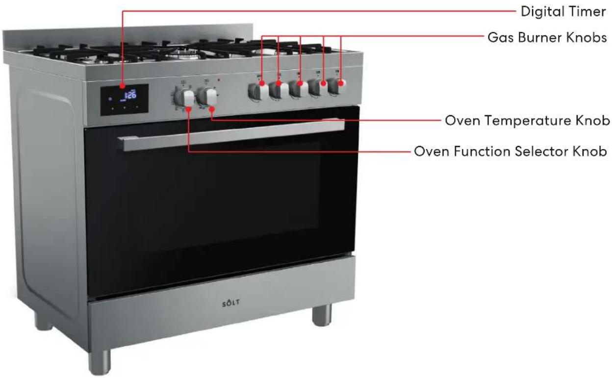
Your Freestanding Cooker
GGSUC908S.1
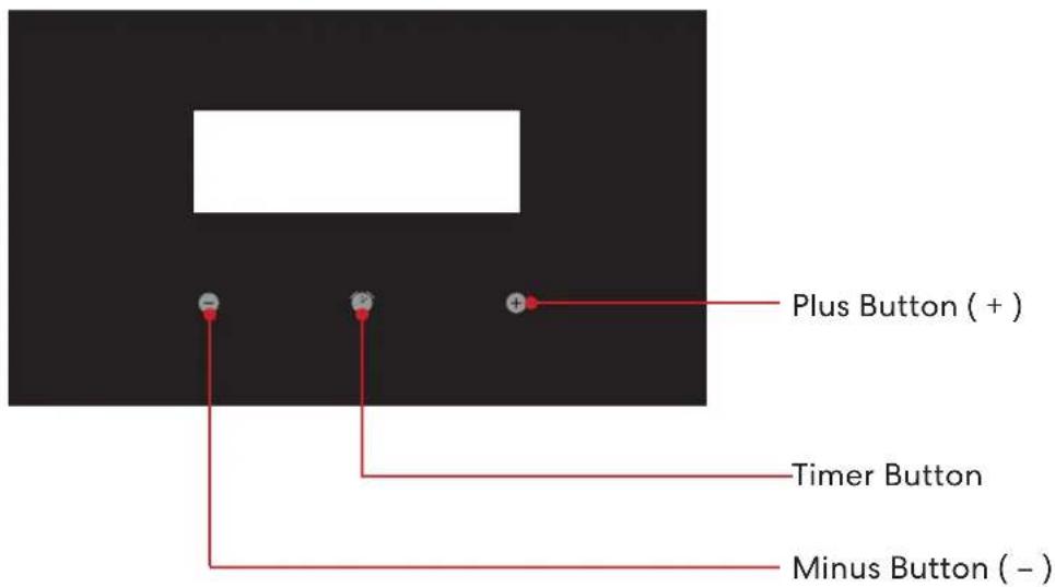
DIGITAL TIMER PANEL
The images and diagrams in this user manual is for reference only. Your Freestanding Cooker may appear differently.
Your Freestanding Cooker (Continued)
COOKING FUNCTIONS

Light
This will activate the two internal lights. No heating elements will be activated.

Defrost
The fan distributes air at ambient temperatures inside the oven for defrosting food evenly and efficiently.

Bake (also known as Conventional)
Heat will come from both the upper and lower elements. The fan is not used in this function. Ideal for cakes and foods that require baking for a long time or at low temperatures. This function is not ideal for multiple shelf cooking.

Fan Assisted Multi-level Oven
Prepare a range of similar or different foods at once using this function.

Fan Forced
By using the central rear heating element and fan, hot air is blown into the cavity and circulated providing a consistent temperature at all levels. Ideal for multiple shelf cooking.
Note: If converting a recipe from Bake to Fan Forced, we recommend that you decrease the bake time or temperature by approximately 20°C.

Lower Element
Cooking using the lower element. Ideal for cooking pastry based dishes by cooking the lower section of your food quicker than the top. Use this for flans, quiches, tarts and any cooking that requires greater heat radiation from below.

Grill
This function uses intense heat from the upper Grill element. This is the most ideal function for finishing off many meals (i.e. browning the top of a roast, frittata or potato gratin).
Note: For best results allow 5 minutes of pre-heating before placing any food into the oven. Ensure your dish is centered under the grill element. Also ensure the temperature is between 50 and grill.

Full Grill
Powerful grilling using both upper grill elements. This is the most ideal function for finishing off many meals (i.e. browning the top of a roast, frittata or potato gratin).
Note: For best results allow 5 minutes of pre-heating before placing any food into the oven. Ensure your dish is centered under the grill element. Also ensure the temperature is between 50 and grill.

Fan Assisted Grill
Fan combined with the upper element and grill element. This function uses the intense heat from the two upper elements for top browning and the fan to ensure even cooking of the food. Ideal for meat, poultry and vegetables, leaving the food crisp and brown on the outside whilst the inside remains moist and tender (i.e. Whole chicken, beef fish or even steak).
USING THE GRILL
The grill is situated in the top of the oven compartment. The grill pan should be located on the top oven shelf position. Always grill with the door closed.
Warning: Do not place fatty foods too close to the grill and never leave the grill unattended. If fatty foods are grilled, or roasting has been cooked in the oven at a high temperature the grill element may smoke. This is not dangerous and the smoke is caused by the fat burning off when the grill element is hot. Leave the grill element on until the smoking has stopped then use as normal. If a grease fire should occur in a pan put out the flame by placing a lid on the pan. Do not throw water on a grease fire.
CLOCK/PROGRAMMER
After power on, '0:00' and the clock icon will flash on the screen, press any button to quit.
Button 1: minus (-)
Button 2:*clock → alarm setting → duration
setting → end time setting → clock
setting →*clock (*:default)
Button 3: plus (+)
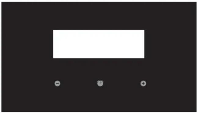
natural_image
Simple black background with a white rectangular shape and three small circular symbols below (no text or labels)Set alarm
- Press button 2, alarm icon flashing means alarm function chosen. "0:00" will display.
- Press button 1 and 3 to set alarm time. Time adjust range is "1:00\~99:00". Press once to plus or minus 1, and hold for 3 seconds for quick-adjust. Waiting for 5 seconds to confirm setting, the alarm icon will be displayed, alarm time will be shown and alarm starts.
- After the count down, "0:00" will display, buzzing starts 4 times every 5 seconds. Press any button to stop.
- If there's no operation for 7 minutes, buzzing will stop.
Duration setting
- Press button 2, choose 'duration' function, duration icon will flash, "0:00" will display.
- Press button 2 and 3 to set duration time, adjusting range is "0:01\~23:59". Press once to plus or minus 1, hold for 3 seconds for quick adjust.
- The flashing will last for 5 seconds, so the settings must be done within this time frame or the time of day will show again. After setting, the duration icon will display, counting down starts.
- When counting down stops, power will turn off, 'Duration' icon will flash, "0:00" will display, buzzing will starts for twice every 5 seconds. Press any button to stop buzzing, and press button 2 to show the time of day.
-
During the cooking duration, press button 2 can check and change the cooking time. After counting down stopping, if there's no operation for 2 minutes, buzzing will stop.
-
If set duration time before end time, end time can only be added, not decreased. (The max time added can be after 23h 59m. When end time is longer than duration time+ current time, end time can be decreased by pressing button 1. It will be decreased until end time equals to duration time+ current time+1 minute). If end time is longer than duration time+ current time, power will be off, end time icon will display. When end time equals to duration time+current time, power will be on again, end time icon will turn off.
Time function
- Press button 2 to choose time function. Time icon will flash, press button 1 or 3 to time. The range is 24hrs.
- Press once to plus or minus 1, hold for 3 seconds for quick-adjust. No operation for 5 seconds, the time of day will show, time icon will turn off.
- If time setting is changed after setting alarm, duration and end time, the alarm will not be changed, and duration and end time will reset.
Other notification
- If setting alarm, duration time and end time, alarm time will display, and alarm, duration, end time icons will display.
- After setting alarm, duration, and end time, Button 2 can be pressed to check and change alarm time, duration time, end time and day time.
- If duration time is later than alarm time, there will be only buzzing for alarm. If duration is earlier than alarm time, there will be only buzzing for alarm.
Operating Instructions
FIRST USE
IMPORTANT! Before first use:
- Remove all packaging and protective films
- Please ensure you have read all instructions in this manual taking note of the safety instructions.
- Ensure the gas supply is turned on and that the appliance is plugged in and switched on.
Position your shelves
After removing any packaging or protective wraps, re-install the shelves in your desired positions
Your Oven
The oven is fitted with:
- a lower heating element;
- an upper heating element;
- two circular heating element surrounding the fan.
N.B.: Always set the temperature on the thermostat knob before selecting any of the functions.
Conditioning the oven
It is important to condition your oven before using it for cooking and baking. Conditioning will burn off any manufacturing residues and ensure that you get the best results right from the start.
- Ensure you have removed all packaging, cable ties and protective wraps/inserts from the oven.
- Ensure that all shelves and baking trays have been re-installed into the oven.
- Make sure that all oven control dials are switched the Off position.
- Use the Function selector knob to select the Bake function. Then use the Oven Temperature knob and set it to 200^ C.
- After 30 minutes, use the Function selector knob to select the Fan Grill function. Leave the temperature set to 200°C.
- After a further 10 minutes, use the Function selector knob to select the Fan Forced function and heat for 20 minutes at 200°C.
- After the final 20 minutes is up, turn both the Function and Temperature knobs to the Off positions.
Note:
There will be a distinctive smell and a small amount of smoke present during this conditioning process, as the manufacturing residues are burnt off. This is normal, but please make sure that the kitchen is well ventilated during this process.
Important!
Once the oven has completely cooled, wipe out the oven and warming drawer with a damp cloth and mild detergent, followed by thoroughly drying.
Description of the main parts of the gas cooktop
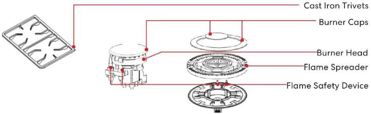
DESCRIPTION OF SYMBOLS
Description of the burner areas of the gas cooktop

Front Left Burner

Middle Wok Burner

Front Right Burner

Rear Left Burner

[Non-Text]

Rear Right Burner
ACCESSORIES
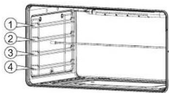
The accessories can be inserted into the oven in 4 different shelf positions, see below.
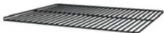
Enamel Baking Tray
Deep Baking Dish

Operating Instructions (Continued)
To light the burner, press the control knob fully down and hold the knob down before rotating anti-clockwise to the High Flame position. The ignition device is integrated into the control knob and is automatically activated by pushing down on the control knob.
After lighting the flame, keep the knob pressed for about 10 seconds: this time is necessary to heat up the thermocouple and activate the safety valve, which would otherwise cut off the gas flow. This step only applies where flame failure device is fitted.
In the instance of a power failure, place a lit match near the burner and proceed as described above. If the flame does not light after the first attempt, wait 5 minutes for the gas to dissipate before attempting to re-light the burner.
Once lit, check that the flame is even and turn the control knob to adjust the flame as required. If the flame is uneven, check that the 'burner head/skirt' and 'burner cap' are correctly positioned. To turn off the flame, turn the control knob clockwise to the off position. Before removing pots or pans from the burners, always turn off the flame.
For correct use of the cooktop
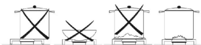
For lower gas consumption and better efficiency, use only flat bottomed pans of dimensions suitable for the burners, as shown in the table below. Also, as soon as a liquid comes to the boil take care to turn the flame down to a level that will just keep it boiling.
| Burner min | Saucepan max | Saucepan |
| Auxilliary 80mm | 160mm | |
| Semi-rapid 120mm | 200mm | |
| Rapid 200mm | 230mm | |
| Triple crown 230mm | 260mm |
natural_image
Four simple line drawings of cooking pots with crossed xenkets, no text or symbols presentCooking Guidelines
Baking
- For best results when baking, always preheat your oven to the desired temperature. The temperature indicator light will switch off to indicate that the set temperature has been reached.
- We advise you do not open the door until at least 34 of the way through cooking.
- Make sure cake pans do not touch each other or the sides of the oven.
- If you are doubling the baking recipe (especially cookies), the cooking duration may need to increase.
- Your cookware will significantly influence baking times. Dark pans absorb the heat more quickly than reflective pans; glass cookware may require a lower temperature.
- Where you are baking using multiple shelves, you may require a slight increase in cooking time.
Shelf Position Guide
- Single shelf: place your baking on a wire rack that will have the top of your pan near the center of the oven cavity, for optimum results.
- Multiple shelves: always leave a space between shelves to allow the air to circulate.
Roasting
- The Roast (or Fan + Grill) function is designed to brown the outside of the meat but still keep the inside moist and juicy.
- Boneless, rolled or stuffed roasts take longer than roasts containing bones.
- Poultry should be well cooked with the juices running clear and an internal temperature of 74^ .
- If using a roasting bag, do not use the Roast function. The initial searing stage is too hot for roasting bags. Use Fan Bake or Fan Forced and follow the manufacturer's instructions.
- When using the Roast function, do not cover your roast, as this will stop the searing process browning the outside of the meat. If you prefer to roast in a covered pan, use the Fan Bake function instead and increase the temperature by 20^ .
- Cook larger cuts of meat at a lower temperature for a longer time. The meat will cook more evenly.
• Always roast meat fat side up. That way, basting may not be required. - Always rest the meat for at least 10 minutes after roasting to allow the juices to settle.
- Remember the meat will continue to cook for a few minutes after removing it from the oven.
Shelf Position Guide
- Place the meat on a shelf so that it is in the center of the oven or lower.
Grilling
- This is a healthier alternative to frying.
• Always grill with the oven door completely shut. - For best results allow 5 minutes of preheat before placing food in the oven.
- If you use glass or ceramic pans, be sure they can withstand the high temperatures of the grill.
- To avoid piercing the meat and letting juices escape, use tongs or a spatula to turn the meat halfway through cooking.
- Brush meat with a little oil to help keep the meat moist during cooking. Alternatively marinade the meat before grilling (but be aware that some marinades may burn easily).
- Where possible grill cuts of meat of a similar thickness at the same time. This will ensure even cooking.
• Always keep a close watch on your food while grilling to avoid charring or burning.
Shelf Position Guide
- For thinner cuts of meat, toasting or browning foods, use a higher shelf position.
- Thicker cuts of meats should be grilled on lower shelves or at a lower grill setting to ensure even cooking.
Reheating food
- Use Bake or Fan Bake to reheat food.
- Bake and Fan Bake are particularly good for reheating pastry based items, as the base heat will help re-crisp the pastry case.
- Always reheat food to piping hot. This reduces the risk of contamination by harmful bacteria.
- Once hot, set the oven temperature to WARM or use the warming drawer to keep food hot.
- Never reheat food more than once.
Cleaning & Maintenance
Important!
Do not use steam cleaners on your appliance.
Important!
Before any cleaning or maintenance operation, use the isolation switch to disconnect the appliance from its power source.
Cleaning Do's
- Read these cleaning instructions and the 'General Safety Instructions' section before you start cleaning your cooker.
- Before cleaning or removing any part, make sure that everything on the cooker has been turned off.
- Unless suggested otherwise in the chart following, allow any part to cool to a safe temperature before cleaning. If you do need to handle a warm or hot part, take extreme care. Wear long protective mitts to avoid burns from steam or hot surfaces.
- Try using any cleaner on a small area first, to ensure it doesn't stain.
- See the pages following this chart for instructions on removing and replacing different parts of the cooker for cleaning or maintenance.
- To help you identify any parts, see illustrations in section 'Your Freestanding Cooker' and the Cleaning Chart on page 17 –19.
- Ensure the anti-tip device is re-engaged if you move the cooker for cleaning. Failure to do this may result in the oven tipping, and adults and children may be killed.
- To prevent soiling from becoming 'baked on' and stubborn, we recommend removing any easy-to reach spills, food or grease stains from the oven cavity enamel after each use.
Cleaning Don'ts
- Do not use aerosol cleaners until the cooker has completely cooled. The propellant substance in these cleaners could catch fire in the presence of heat.
- Do not let soiling or grease accumulate anywhere in or on the cooker. This will make future cleaning more difficult and may present a fire hazard.
- Do not use any abrasive or harsh cleaners, cloths, scouring pads or steel wool. These will scratch your cooker and damage its appearance.
- Do not use a steam cleaner to clean any part of the cooker.
- Do not perform any cleaning or maintenance on parts not specifically named in the chart below. If in doubt, contact Customer Care on 1300 11 HELP (4357).
- Only an authorised service technician can take apart the door- after training.
- Do not attempt to take the door apart for cleaning. If the inner panes of glass in the door become dirty, please contact your InAlto trained and supported service technician or our After Sales Service team on 1300 11 HELP (4357).
Cleaning Chart
| Component / Part Cleaning | Method Important Notes | ||
| Freestanding Oven Exterior | Door frame exterior, Control panel, Cooktop base, Back trim, Warming drawer exterior, After every use | 1. Soften any stubborn stains under a hot soapy cloth.2. Clean with a solution of mild detergent and hot water, then wipe dry with a microfibre cloth.Stainless steel models:For extra shine, use a suitable stainless steel cleaner and polish, following manufacturer's instructions. Always rub the stainless steel in the direction of the polish lines. | ·Always read the label to make sure your stainless steel cleaner does not contain chlorine compounds as these are corrosive and may damage the appearance of your cooktop.·Do not use and take care not to spill any stainless steel cleaner on the dials, oven handles, or the kickstrip grate. These are not stainless steel parts and their surface may be damaged by stainless steel cleaner. |
| Dials & Oven handles | 1. Wipe with a damp cloth using a solution of mild detergent and hot water.2. Dry thoroughly with microfiber cloth. | Do not use stainless steel cleaner on these parts, as doing so may damage their coating. | |
| Clock / Timer | Take particular care when cleaning the clock and surrounding area. Only use a damp cloth with detergent. | Do not use any oven cleaners, harsh or abrasive cleaners, scouring pads, steel wool or sharp metal scrapers on the glass.These may scratch and damage the surface. | |
| Oven door glass (exterior) | Clean using a soft cloth and a mixture of warm water and dishwashing liquid or glass cleaner. | — | |
| Oven Interior & Parts | Enamel oven interior - light soiling | 1. Wipe with a damp cloth using a solution of mild detergent and hot water.2. Wipe dry with a soft cloth.Note:The oven door may be removed to make reaching into the oven easier. | To prevent soiling from becoming 'baked on' and stubborn, we recommend removing any easy to reach spills, food or greasy stains from the enamel after each use. |
| Enamel oven interior - stubborn, 'baked-on' soiling | You may need to use an oven cleaner. | Oven cleaners are caustic and may permanently stain or damage some surfaces.When using, take care not to let it come in contact with any surface other than the oven interior. If it accidentally does, remove immediately. | |
| Chrome Side Racks | Clean with a solution of mild detergent and hot water. | — | |
| Oven Shelves / Wire Racks | Wipe with a damp cloth and mild detergent. | Be careful cleaning any telescopic rails/guides- Do not wipe off or wash away the white lubricating grease (visible when the shelf is extended) | |
| Roasting dish and grill rack | 1. Pre-soak any stubborn soiling in a solution of mild detergent and hot water.2. Wash by hand or in a dishwasher. | — | |
Cleaning & Maintenance (Continued)
Cleaning Chart (Continued)
| Component / Part Cleaning | Method Important Notes | ||
| Oven Interior & Parts(Continued) | Grill elements | Do not clean these parts.They self-clean during normal use. | — |
| Oven door glass (interior) | Use a soft cloth and a mixture of warm water and dishwashing liquid to remove light soiling after every use.For stubborn stains, try using a mixture of baking soda and warm water with a non-abrasive scrubbing pad, then wipe dry with a soft, lint-free cloth. | Do not use oven cleaners or any other harsh/abrasive cleaners, cloths, scouring pads, steel wool or sharp metal scrapers to clean the oven door glass. These scratch the glass, which in turn could result in the glass cracking and shattering.Do not allow grease to build up on the glass or become baked on as this reduces visibility into the oven.Only a trained and supported service technician can take apart the door.Do not attempt to take the door apart for cleaning. If the inner panes of glass in the door become dirty, please contact our After Sales Service team on 1300 11 HELP (4357). | |
| Oven door gasket | Avoid cleaning this part.If you need to remove large food particles off it, proceed as follows:1. Dampen a sponge with clean hot water.2. Gently wipe off the soiling, but do not rub.3. Press a dry towel gently on the gasket to dry. | Do not use any cleaning agent on the gasket.The gasket is essential for a good seal. Take care not to rub, displace, or damage it. | |
| Warming drawer (interior) | 1. Wipe with a damp cloth and a solution of hot water and mild detergent.2. Wipe dry with a soft cloth.Note:The drawer may be removed to make cleaning easier. | To prevent soiling from becoming ‘baked on’ and stubborn, we recommend removing any easy to reach spills, food or greasy stains from the enamel after each use. | |
| Cooktop | Burner caps and flame spreaders | 1. Check that the burner is turned OFF and allow it to cool.2. Lift off the burner cap and brass flame spreader.3. Wash them in hot soapy water, rinse, and dry.4. Use a stiff nylon brush or straight-ended paper clip to clear the notches of the flame spreader.5. Replace the flame spreader and burner cap correctly.Brass burner parts only:For extra shine and to remove tarnish use a suitable brass cleaner and polish, following manufacturer's instructions. | ·Keep the notches of the flame spreaders clear. Soiling may clog these and cause ignition problems.·Before replacing the burner parts, check that they are dry.Wet burner parts may result in an irregular flame.·Before lighting a burner you have reassembled, check that all of its parts are positioned correctly. Incorrect assembly can cause dangerous irregular flames and ignition problems.·Do not put any burner parts in the dishwasher as they will become discoloured. |
| Ignitors | 1. Check that the burner is turned OFF.2. Clean the ignitor with a small brush (e.g. old toothbrush) or cotton swab that has been dipped into rubbing alcohol. | The ignitors must be kept clean and dry to work correctly. Dirty or wet ignitors could cause constant clicking and sparking, even if a flame is present. | |
| Trivets | 1. Wait until the trivets have cooled completely.2. Carefully lift the trivets off the cooktop and place them on a protected surface.3. To remove stubborn stains, soak the trivets in a mixture of clothes washing detergent and water.4. Wash in a mixture of hot water and dishwashing liquid, then rinse and allow to dry.Note:The trivets are dishwasher-safe. | ·Take care, the trivets are heavy and can damage your cooktop surface or benchtop if dropped or dragged.·Make sure you place a dishcloth or other soft cover on the surface before putting a trivet on it. | |
Cleaning & Maintenance (Continued)
Removing the oven door
Important! Switch the oven off at the isolating switch before removing the door.
- Do not lift the oven door by its handle. Doing so may damage the door.
- Make sure the oven and the door are cool before you begin to remove the door.
- Before removing the door, make sure there is a large enough clear, protected surface in the kitchen to rest the door on.
• Take care, the oven door is heavy!
Proceed as follows:
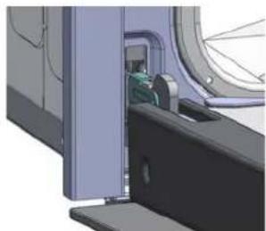
- Open the door to the full extent (Fig. 1);
- Open the lever A completely on the left and right side hinges (Fig. 2);
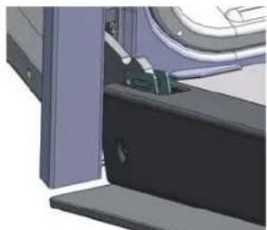
- Hold the door in position as shown (Fig. 3);
• Gently close the door until left and right hinge levers A are hooked to part B of the door (Fig. 4);
natural_image
3D CAD model of a mechanical assembly with no visible text or symbols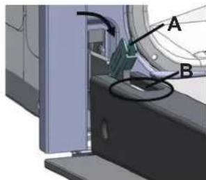
Fig. 1 Fig. 2
natural_image
Close-up of a mechanical assembly with a bracket and mounting base (no visible text or symbols)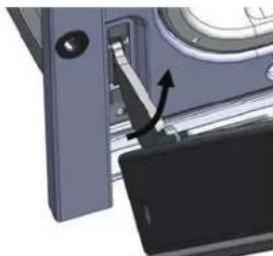
natural_image
Close-up of a mechanical component with an arrow indicating a turning point (no visible text or symbols)Fig. 3 Fig. 4
Removing the chrome side racks
Important! Switch the oven off at the isolating switch before removing the side racks.
- Ensure that the oven has completely cooled down before starting.
- Open the oven door.
- Remove all shelves for either the oven (Fig. 5)
- Slightly squeeze the bottom two row of the runner under the screw (Fig. 6).
- Whilst squeezing the bottom two rows, pull the runner away from the side of the oven chamber (Fig. 6).
- To refit the runners follow these steps in reverse order.
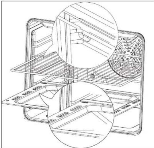
natural_image
Technical line drawing of a multi-tiered appliance with internal components and mounting holes (no text or symbols)Fig. 5
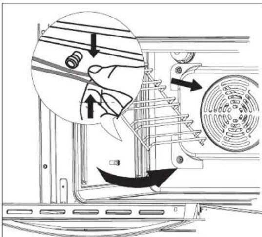
Fig. 6
Cleaning the burner parts
- You can remove and clean these parts with hot soapy water or non-abrasive detergents. Clean spills regularly before they become burnt on. Do not wash these parts in a dishwasher.
• After cleaning, check that the burners and their flame spreaders are dry before replacing correctly. - It is very important to check that the burner flame spreader and the cap have been correctly positioned. Failure to do so can cause serious problems.
- Check that the ignitor is always clean to ensure trouble free sparking. It must be cleaned very carefully using a toothbrush and methylated spirits.
Note:
To avoid damage to the electronic ignition, do not try to light a burner without all burner parts in place.
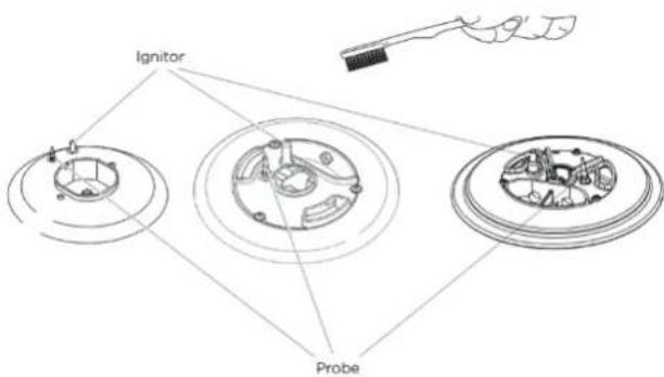
Replacing the burner parts
- Carefully replace the burner parts as per the following illustrations.
- Fit the flame spreader to the housing as shown below. Make sure the burner is not able to rotate.
Check that:
- The ignitor is always clean to ensure trouble-free sparking.
- The probe is always clean to ensure correct operation of the safety valves.
- The flame spreaders are clean and the holes are not clogged.
Note:
Both the ignitor and probe must be very carefully cleaned using a toothbrush and methylated spirits.

natural_image
Technical line drawing of a mechanical assembly with three views: top view showing a circular component, middle view showing a ring and housing, bottom view with a mechanical housing (no text or symbols)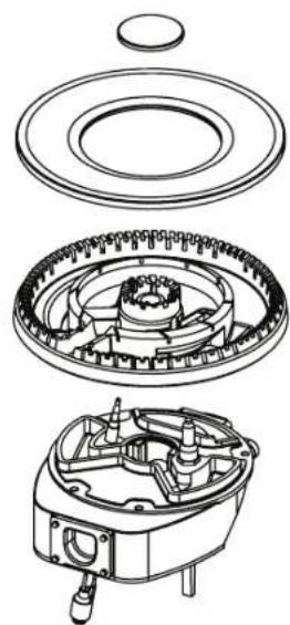
natural_image
Exploded view diagram of a mechanical assembly showing internal components like gears and housing (no text or labels)Cleaning & Maintenance (Continued)
If a burner does not light
Turn the control dial to O (OFF) and wait at least one minute before trying again, to all the gas to disperse. If the burner still does not light, check that:
- The cooker is plugged in and the power supply is switched on
- There is no power failure in your home or neighbourhood
• The gas is turned on
• The gas bottle is not empty (if you use bottled gas) - The flame spreaders are clean and the holes are not clogged
• The ignitors are sparking. If they are not sparking, they may be dirty or wet. Clean them with a toothbrush and methylated spirits, as shown below.
Cleaning the ignitor & probe
If the flame is irregular, check that the burner parts (flame spreader and burner cap) are:
- Clean and dry
- Positioned correctly, as shown below.
Replacing an oven bulb
Important! Use a 25W, 220-240V 50Hz
E14 halogen bulb for replacement. Do not use a standard light bulb in any oven, the heat will break it.
- Allow the oven (including the lamp cover and the bulb) to cool completely.
- Remove any shelves that may get in the way.
- Remove the door if the lamp will be hard to reach.
- Turn the power supply to the cooker off at the main fuse or circuit breaker panel. If you don't know how to do this, contact an electrician.
Important! Failure to disconnect the cooker from the power supply may result in death or electrical shock.
- Remove the lamp cover by screwing the glass cover anti-clockwise.
- Replace the faulty bulb.
- Replace the lamp cover by screwing the glass cover back into place clockwise.

natural_image
Technical line drawing of an oven with two circular vented chambers (no text or symbols)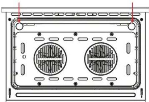
natural_image
Technical line drawing of a rectangular electronic device with two circular heat sinks and mounting holes (no text or symbols)Installation Instructions
PRIOR TO INSTALLATION
Unpacking and product handling
- Thoroughly inspect the freestanding oven to ensure there is no damage from shipping or moving. If any damage is detected, please call the shipper and initiate a damage claim. The distributor of InAlto is not responsible for any shipping damage.
- Do not discard any packaging materials until the freestanding oven has been inspected and found to be free of damage.
- Remove the outer cardboard box and any packing materials from the freestanding oven. Note: Some models are supplied with a protective film on the stainless steel parts which must be removed before installing and using the appliance.
Product Dimensions
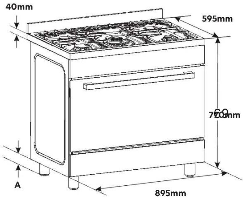
A. Feet adjustment: 89–149mm
Important! Despite their capacity to adjust up to 149mm, Sôlt suggests not extending the adjustable feet beyond 130mm as stability cannot be guaranteed beyond this point.
The images and diagrams in this user manual is for reference only. Your Freestanding Cooker may appear differently.
Installation Instructions (Continued)
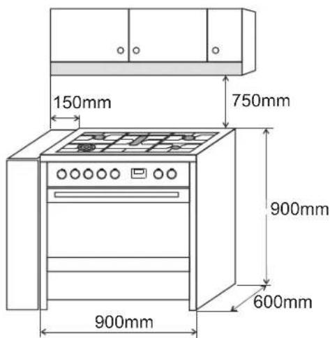
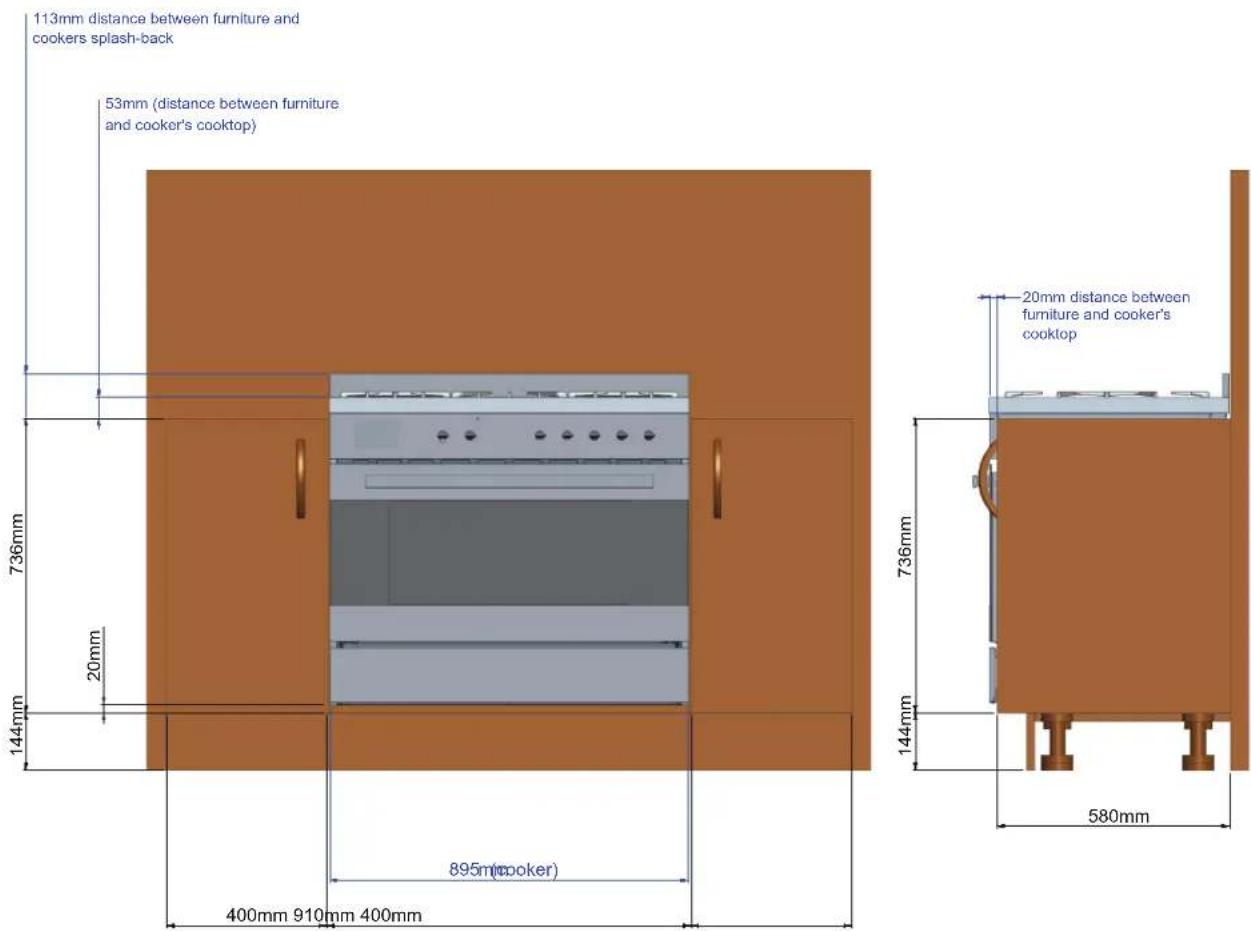
FREESTANDING OVEN CLEARANCES

| Product Dimensions MM | |
| A) Minimum vertical distance between benchtop and cabinet extending above the counter | 400 |
| B) Minimum clearance from left and right hand edge of the freestanding oven to the nearest combustible surface* | 100 |
| C) Please refer to your rangehood's user manual for minimum clearances for the top of the burner cap (cooking surface) to your rangehood. | — |
| D) Width of cabinetry opening 900 | |
| E) Maximum height of cabinetry immediately adjacent to the freestanding oven (from floor to countertop)** | 946 |
| F) Maximum depth from wall to cabinetry face 600 |
* Installation clearances and protection of combustible surfaces shall comply with the current local regulations e.g. AS/NZS5601.1 (latest edition) Gas Installations code. The standards above specify that where required protection shall ensure that the surface temperature of the combustible surface does not exceed 65°C above room temperature.
** Depending on the height of the feet adjustment. The cooking surface must sit flush or above countertop level.
Important Notes:
Compliance
This appliance must be installed by an authorised person and in compliance with:
• AS/NZS 5601.1 Gas Installations Part 1: General Installations, and AS/NZS 5601.2 Gas
Installations Part 2: LP Gas installations in caravans and boats for non-propulsive purposes, or the relevant installation code for gas appliances in your country.
- The local gas fitting regulations, municipal building codes, electrical wiring regulations and any other relevant statutory regulations.
- The particular instructions as given below.
- A certificate of compliance MUST be given to the customer after the application is successfully installed.
CAUTION: This appliances is suitable for us with Natural Gas or ULPG. The cooktop is shipped from the factory set and adjusted for Natural Gas. It can be converted for use with ULPG following the instructions within this manual.
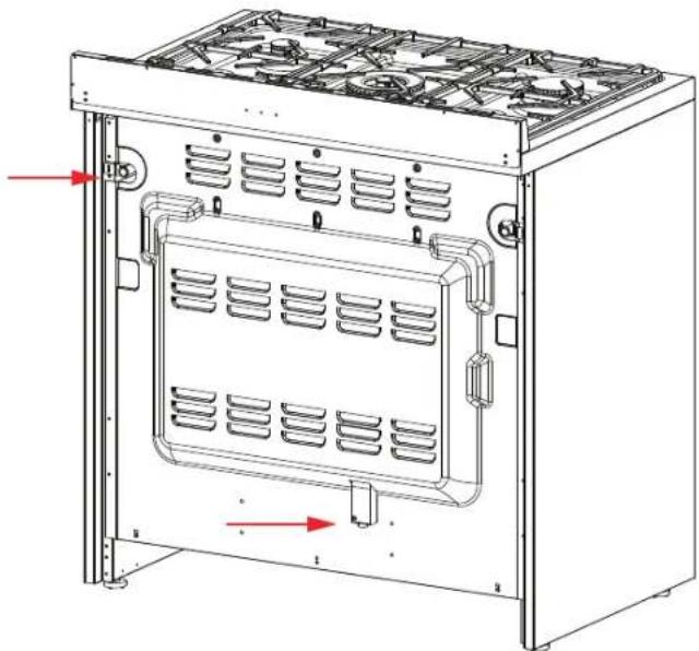
The connection must be made at the rear of the appliances. Ensure that the pipe does not cross the cooker. Refer Gas Connection on page 34.
Adjacent walls, cupboards and protection for combustible materials: Ensure that the appliance is installed in accordance with AS/NZS 5601.1, or AS/NZS 5601.2 with regard to clearances to combustible surfaces and materials, and clearances to rangehoods and exhaust fans.
To ensure clearances of 200mm from burners to vertical combustible surfaces observe the minimum distance requirements shown in the table below.
Clearances to combustible surfaces may be reduced if combustible surfaces are protected in accordance with AS/NZS 5601.1, or AS/NZS 5601.2.
Rear and Side Clearances
- Where the dimensions from the periphery of the nearest burner to any vertical combustible surface is less than 200 mm the surface shall be protected in accordance with the standards to a height of not less than 150 mm above the cooking surface for the full width or depth of the cooking surface.
- Where the dimensions from the periphery of the nearest burner to any horizontal combustible surface is less than 200 mm, the horizontal surface shall be greater than 10 mm below the surface of the hob, or the horizontal surface requirement above.
- Do not install the appliance near flammable materials such as curtains.
Installing the cooker on a plinth
- The freestanding oven can be installed on a plinth without the adjustable feet fitted.
- Ensure the freestanding oven is secure and provide safety measures to keep it in place.
- Cabinetry dimensions can be adjusted to suit the plinth height, see product dimensions for chassis height.
• See Page 31 for more information.
Installation Instructions (Continued)
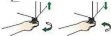
LEVELLING THE FEET
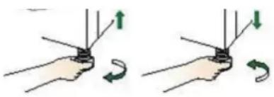
The height and level of the appliance can be adjusted by rotating the feet located underneath the appliance at each corner. Rotate the feet to decrease or increase the height
natural_image
Illustration of two hands holding a small object with directional arrows indicating rotation (no text or symbols)FITTING THE SAFETY STABILISER CHAIN
WARNING! In order to prevent accidental tipping of the appliance, for example a child climbing onto the open oven door, the stabilising means must be installed. Ensure the chains are correctly anchored to prevent the appliance from tilting forward and to prevent strain on the hose when the cooker is pulled forward.
MAKE SURE THAT THE ANTI-TILTING CHAINS ARE TIGHT WHEN ANCHORED TO PREVENT THE APPLIANCE
TILTING./Your freestanding oven is supplied with a safety stabiliser chain attached to the rear of your oven to prevent the appliance from tilting forward and accidental damage to the gas connection.
Fasten the stability hook provided by inserting a wall plug into the kitchen wall and then connect the safety chain to the hook via the locking mechanism.
Determine the suitable location in your wall for the location of the anchor hook. Drill a hole and firmly insert the wall plug/anchor into your wall, followed by screwing the hook into the wall plug/anchor. Fix the chain to the hook and adjust the level of your freestanding oven using the feet provided. The chain and hook should be positioned to prevent the appliances from moving no more than 80% of the gas hose length (i.e. allowing for no strain to be put on to the gas connection).
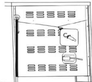
For a built-in installation, where your oven is installed between cabinets on a plinth, we suggest securing your oven through both sides of the cupboards into the sides of the freestanding oven. The screws should be fitted as follows.
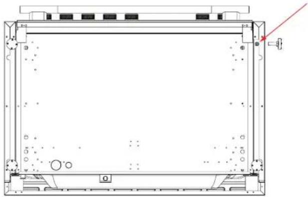
Refer to the diagram below for the location of the pilot hole. Use 3.5mm diameter drill bit to drill the pilot hole through the cupboard and both sides of the cooker.
natural_image
Diagram of a room with ventilation grilles and a hanging tool, no text or symbols presentBefore drilling, check your measurements to ensure the pilot holes are located within the range specified in the diagram.
A drilled hole in the side of the cooker which is outside the range specified may void the warranty. Inspect cupboards thoroughly before drilling to avoid damage to electrical wires or gas lines. Fix two 12 gauge x 40mm long self tapping screws through the pilot holes inside both cupboards and into the side of the cooker.
- Safety chain (supplied and mounted to oven)
- Stability hook
- Chain attachment for the rear of the cooker
- Rear of the cooker
- Kitchen wall


Note:
The screw length suggested above is based on a cabinetry thickness of 20mm and a gap between the cabinetry and the freestanding oven of 10mm. Adjust the screw length accordingly to suit your cabinetry thickness and any gap between the cabinet and the oven.
Note:
The screws must be accessible for removal if the cooker requires service. Cabinetry must not be installed preventing access to these screws.
Possibility of tilting

Anti-tip restraint

INCORRECT CHAIN INSTALLATION
WARNING: Accidental Tipping
Chains are provided as a preventative measure against accidental tipping. These chains must be fitted as part of the installers compliance. Failure for your installer to fit chains in accordance with the relevant installation code will make the installation of your freestanding cooker non compliant and classed as an illegal installation.
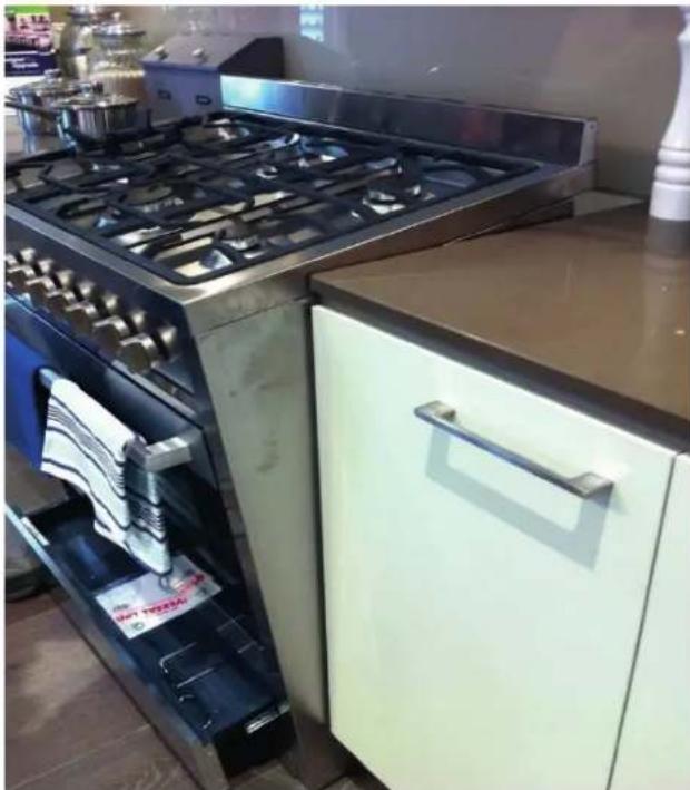
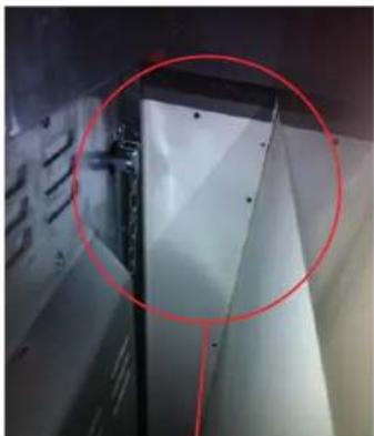
The photographs on this page are just some examples of incorrect installation (not exhaustive) which do not have the chains sufficiently secured.
natural_image
Modern kitchen oven with open door and stainless steel stove, no visible text or symbolsThis photograph shows how far forward a freestanding cooker can tip when it not secured properly.
Note: Correct installation is part of the installers compliance.
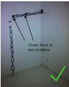
Putting the chain into the adjacent cabinet is the preferred method providing there is no slackness in the chain.
If the installation only has one chain fixed, the installation is non-compliant. Both chains must be fixed in the installation as part of the installers compliance.
Left side of the oven:
Chain not attached. Loose chain
natural_image
Close-up of a white panel with a red circle highlighting a specific edge, no visible text or symbolsHole in cabinet is too large, allowing the upright cooker to tilt forward

natural_image
Close-up of a mechanical or electrical component with coiled cables and a black connector, circled in red (no visible text or symbols)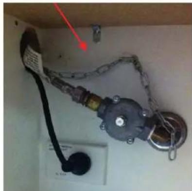
natural_image
Electrical wiring harness with attached cable and motor (no visible text or symbols)The images and diagrams in this user manual is for reference only. Your Freestanding Cooker may appear differently.
Installation Instructions (Continued)
CORRECT CHAIN INSTALLATION
In order to prevent the oven from tipping forward as shown on the previous page, ensure that both chains provided with the oven are used. View the example below:
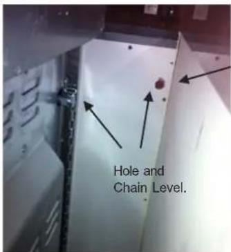
On the left side of the oven, a 16mm drill bit was drilled through the cabinetry into the adjacent cabinet. Because of the 16mm board at the rear of the cabinet, the hole has not been drilled hard up against the wall. The height of the hole from the floor is level with where the chain attaches to the oven.
The right side of the oven is drilled much the same, and an additional hole is drilled below the gas and power supply hole.
Once the holes have been drilled, the chains can then be fed through. Your freestanding cooker could then be fitted into position.
The chains then need to be pulled as tight as possible from inside the cabinet while at the same time being fixed to the rear of the cabinet using a self-drilling wood screw. It is better to have the screw fixed closer to the hole for better support. In the left and right side examples, two extra screws are attached to the chain which makes the installation neater by keeping the chain off the shelf away from the gas and electricity supply, and it will also provide added support.
At this point, the oven will be secured in location and will not move forward at all. It is recommended that all upright cooker chains be fitted in this way.
WARNING: The installation forms part of the installers compliance and that are in line with regulations. The chains are to be installed to prevent cooker from tilting.
They do not replace parental supervision when the freestanding cooker is in use.
Left Side Right Side

natural_image
Close-up of a mechanical pipe fitting inserted into a wall socket, with no visible text or symbols.
The images and diagrams in this user manual is for reference only. Your Freestanding Cooker may appear differently.
LOCATION OF GAS POINT AND ELECTRICAL SUPPLY
natural_image
Technical line drawing of a multi-level industrial oven or rack unit with ventilation grilles and cooling pipes (no text or symbols)VENTILATION REQUIREMENTS
A suitable ventilation hood may be installed above your freestanding oven. InAlto has a wide range of ventilation hoods designed to match the rest of our kitchen appliance family. See www.inalto.house or your local retailer for more details.
IMPORTANT! Consult local building codes and/or local agencies, before starting, to ensure that your hood and duct installation will meet local requirements.
Hood blower speeds should be variable to reduce noise and loss of heated or air-conditioned household air when maximum ventilation is not required. Normally, the maximum blower speed is only required when using the grill or frying at a high temperature on your gas cooktop.
FITTING THE ADJUSTABLE FEET
The adjustable feet must be fitted to the base of the freestanding oven before use. Rest the rear of the freestanding oven on a piece of the packaging (i.e. the polystyrene) exposing the base for the fitting of the feet.
IMPORTANT! Be very careful not to damage the freestanding oven during this process. Do not have any of the burners or trivets fitted in place when lying the cooker backwards. The freestanding oven is heavy- ensure that you have adequate help.
Fit the four legs by screwing them tight into the support base as shown below.
natural_image
Technical line drawing of a rectangular enclosure or enclosure with internal components and a red arrow pointing to a detail (no text or symbols present)
natural_image
Technical line drawing of a rectangular electronic device with mounting holes and a red arrow pointing to a component (no text or symbols present)Installation Instructions (Continued)
LEVELLING THE FREESTANDING OVEN
- The feet have built in adjustment and the lower section can be twisted clockwise or anticlockwise to raise or lower the freestanding oven.
- Small adjustments can be made with the freestanding oven standing up on its feet, however you may need to lie the freestanding down to make larger adjustments.
natural_image
Illustration of two hands holding a tool with directional arrows indicating rotation (no text or symbols)MOVING YOUR FREESTANDING OVEN
IMPORTANT! When lifting the freestanding oven to the upright position, always ensure that you have a minimum of two people to carry out this maneuverer to prevent damage to the adjustable feet. Be careful to avoid too much pressure on any two feet during this process.
- Never lift the freestanding oven by using the oven door handle, the cooktop rail or by lifting the cooktop trim as this may damage the appliances.
- Lift the feet clear of the floor.
INSTALLING THE COOKER ON A PLINTH
IMPORTANT!
Kitchen cabinets must be made of materials capable of withstanding temperatures at least 65^ C ( 117^ F) above room temperature. This is necessary to avoid possible damage to the cabinets during oven usage.
Note:
- When installing as a built-in appliance, secure it on a raised platform using suitable fastening systems.
- DO NOT install the adjustable feet that come with the appliance.
• DO NOT modify this appliance in any way
The images and diagrams in this user manual is for reference only. Your Freestanding Cooker may appear differently.
Electrical Connection
IMPORTANT! This freestanding oven must be connected to the mains power supply only by a suitably qualified person. This freestanding oven must be earthed.
The appliance must be installed by a suitably qualified person in accordance with these instructions and with the requirements of the Australian Wiring Rules AS/NZS 3000. Fixed wired installations are to be provided with suitable isolation means in accordance with the said rules. Any plug socket installed for the purpose of connecting the appliance to supply must be readily accessible when the appliance is installed.
Before making the connection, make sure that:
1) The safety circuit-breaker and the electrical system are able to withstand the load of the appliance (see nameplate).
2) The power supply system has an earth connection in good working order in accordance with the regulations in force
The appliance is fitted with an approved 15 Amp flexible cord and plug which must be connected to a correctly earthed socket outlet. The manufacturer is not liable for any direct or indirect damage caused by faulty installation or connection. It is therefore necessary that all installation and connection operations are carried out by qualified personnel complying with the local and general regulations in force. If the supply cord is damaged, it must be replaced by an authorised service agent.
IMPORTANT
The wires in the mains lead are coloured in accordance with the following code:
GREEN & YELLOW...... EARTH
BLUE NEUTRAL
BROWN ...... LIVE
Electric power 1.5 mm ^4 3 core cable
(15 amp. Fuse required).
Should conform to local authority requirements.
WARNING: THIS APPLIANCE MUST BE EARTHED.
REPLACING THE POWER CORD
- Replacements should only be made by a qualified electrician.
- Use a cable according to the applicable local regulations.
- The wire section on the cable must not be less than 1.5mm^2 ( 3 × 1.5mm cable). Only use the cables available from our After Sales Service team on 1300 11 HELP (4357).
-
If the installation requires alterations to the domestic electrical system, call a qualified electrician. The electrician should also check that the electrical system is suitable for the electricity drawn by the cooker.
-
The appliance must be connected to the mains electricity supply, checking that the voltage corresponds to the value given in the rating plate and that the electrical cable sections can withstand the load specified on the plate.
- A suitable disconnection switch must be incorporated in the permanent wiring, mounted and positioned to comply with the local wiring rules and regulations. The switch must be of an approved type installed in the fixed wiring and provide a 3mm air gap contact separation in all poles in accordance with the local wiring rules.
- A switch of the approved type with a 3mm air gap must be installed in the active (phase) conductor of the fixed wiring.
- The switch must always be accessible.
- The power supply cable must not touch any hot parts and must be positioned so that it does not exceed 75°C at any point. This cooker must be connected to a suitable double pole control unit adjacent to the cooker. No diversity can be applied to this control unit.
- This appliance must be connected to the electrical supply using a cable fitted with an appropriately rated plug. The plug must be compatible with the socket-outlet fitted to the final sub-circuit in the fixed wiring that is intended to supply the appliance.
CONNECTION OF THE POWER SUPPLY CABLE
IMPORTANT! The power supply cable must be connected by an authorized service person. DO NOT unscrew the screws fixing the cover plate behind the terminal block.
Connect the feeding cable to a plug suitable for the load indicated on the rating plate of the product. In case of a direct connection to the mains (cable without plug), it is necessary to insert a suitable omnipolar switch before the appliance, with minimum opening between contacts of 3 mm (the grounding wire should not be interrupted by the switch).
Before connecting to the mains, make sure that:
- The electrical counter, the safety valve, the feeding line and the socket are adequate to withstand the maximum load required(see rating plate).
- The supply system is regularly grounded, according to the regulations in force. The socket or the omnipolar switch can easily be reached after the installation of the oven.
• After carrying out the connection to the mains, check that the supplying cable does not come into contact with parts subject to heating. - Never use reductions, shunts, adaptors which can cause overheating or burning.
Gas Connection
IMPORTANT! The connection must be performed by an authorised person according to the relevant standards.
- This appliances is suitable for us with Natural Gas or ULPG. The cooktop is shipped from the factory set and adjusted for Natural Gas. It can be converted for use with ULPG following the instructions within this manual.
- The connection must be made at the rear of the appliances. Ensure that the pipe does not cross the cooker.
INSTALLATION WITH A FLEXIBLE HOSE ASSEMBLY
- If this appliance has to be installed with a hose assembly, the installer shall refer to the network operator or gas supplier for confirmation of the gas type, if in doubt.
- When used with a flexible hose, the connector on the wall should be between 450mm to 500mm from the floor and 200 mm to 300 mm from the left-hand side of the appliance as viewed from the front. The hose connection on the appliance shall face downwards.
- It is important that the hose does not come in contact with the metal of the appliance and is secured as per appropriate gas installation codes. The stabilising chain (installation of the chain referred to within this manual) should be installed to restrict movement of the appliance to no more than 80% of the length of the flexible gas hose. The chain should be attached securely to the product where shown, and on the wall.
- Flexible hose assemblies should be AS/NZS 1869 Class B or Class D certified. The thread connection shall be Rp 12 " (ISO 7-1) male.
- The hose assembly shall be as short as practicable and comply with relevant AS5601 / NZS5261 requirements.
IMPORTANT! After connection the installer must check that the hose is not kinked, subjected to abrasion or permanently deformed. The installer must check also that the hose is not near (or in contact) with any hot surfaces.
GAS CONNECTION SPECIFICATION
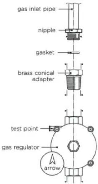
IMPORTANT! Check the correct positioning of the gas regulator. The arrow on the back of the gas regulator must be oriented toward the connector.
Natural Gas
Adjust to obtain a test point pressure of 1 kPa with all the burners operating at highest setting.
ULPG
Ensure the supply pressure is regulated to 2.75 kPa, with all the burners operating at highest setting.

Gas Connection (Continued)
GAS CONNECTION
IMPORTANT! The connection must be performed by an authorised person according to the relevant standards.
Natural Gas
flowchart
graph LR
    A["Top bolt"] --> B["Bottom bolt"]
    B --> C["Hexagonal nut with bolts"]
ULPG

flowchart
graph LR
    A["Raw Material"] --> B["Product"]
    B --> C["Final Product"]
Note:
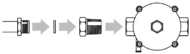
Before connecting the appliance to the gas main, mount the brass conical adaptor onto the gas inlet pipe, ensuring the supplied gasket is positioned between.
Natural Gas
Connect gas supply to the pressure regulator and adjust the regulator to obtain a test point pressure of 1 kPa with the two semi-rapid (SR) burners operating at maximum.
LP/Propane
Connect gas supply to the test point adaptor and ensure that the supply pressure is regulated to 2.75 kPa
IMPORTANT! Use two wrenches to tighten the connection. Do not over tighten the connector. Over tightening may crack regulator.
IMPORTANT! If your model features two inlets allowing for flexibility of installation, you must close off the inlet not being used with the cap and sealing gasket supplied.
LEAK TESTING
When the installation is complete, always check for gas leaks using a soapy solution.
- Ensure all oven and burner knobs are set to OFF before connecting range to gas supply.
• After final gas connection is made, turn gas supply on and test all connections in gas supply piping for gas leaks with a soapy water solution. - In order to avoid property damage or serious personal injury, never use a lit match or open flame. If a leak is present, tighten joint or unscrew, apply more joint compound, tighten again and retest connection for leak.
FLAME TESTING
The operation of the appliance must be tested when installation is completed, including ensuring the burners are operating correctly.
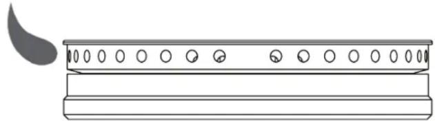
- Turn on the appliance gas controls and light each burner individually and in combination. Check for a well defined blue flame without any yellow tipping. If any abnormality is evident then check that the burner cap is located properly and the injector nipple is aligned correctly.
- Check the minimum burner setting by quickly rotating the gas control knob from the maximum to the minimum position. The flame must not go out. If adjustment is required see section "Adjusting the minimum burner setting".
✗ No Flame Lifting Off
natural_image
Simple line drawing of a traditional Chinese musical instrument with a curved blade and two circular holes (no text or symbols)× No Yellow Tip Flame

natural_image
Simple line drawing of a traditional Chinese musical instrument with a curved blade and circular holes (no text or symbols)√ Good Flame

natural_image
Line drawing of a traditional Chinese musical instrument with a curved blade and circular holes (no text or symbols)In case the appliance fails to operate correctly after all checks have been carried out, please call our After Sales Service team on 1300 11 HELP (4357).
CONVERSION TO ULPG
- This freestanding oven can be used with Natural Gas or ULPG. It is shipped from the factory adjusted for use with Natural gas.
- Any conversion required must be performed by an authorised person or service agent.
- The range is supplied with a set of injectors required for converting the range burners.
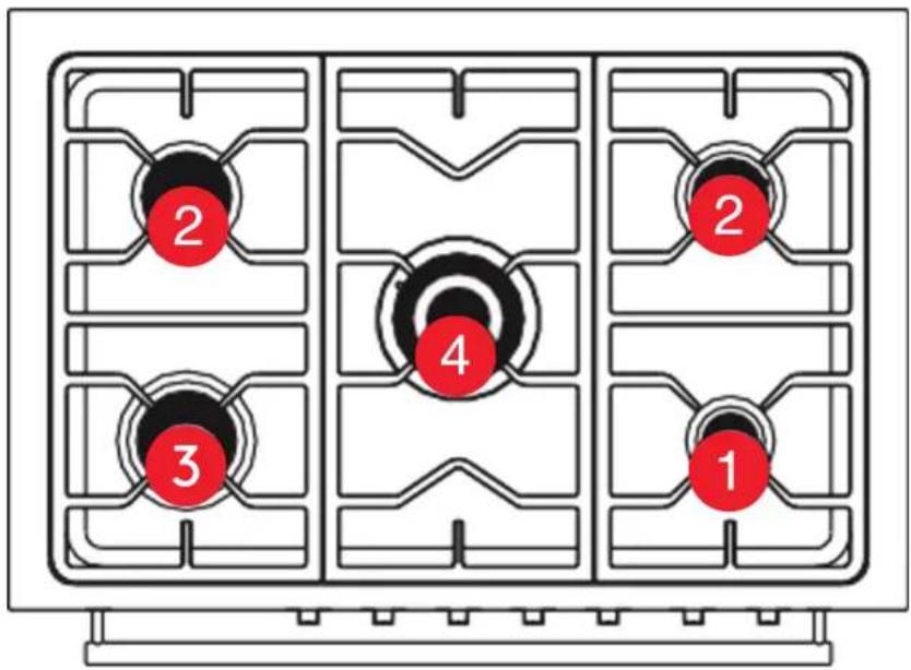
- Refer to the following table to select the appropriate size injector. The nozzle diameters (hundredths of a millimetre) are marked on the body of each injector.
IMPORTANT! After converting the burners repeat the flame testing process outlined within this manual.
• If the range has been disconnected and re-connected to the gas supply line repeat leak testing.
• After conversion to ULPG gas affix the supplied conversion label near the data plate on the product, as well as at the beginning of this manual.
• If the range is being converted for use ULPG, before connecting to the gas
| Burner | Natural gas1.0 kPa | Universal LPG2.75 kPa | |||
| Injector (mm) Po | wer MJ/h Injector (mm) Power MJ/h | ||||
| 1 | Auxiliary 0.90 4.0 MJ | 0.53 3.7 MJ/h | |||
| 2 | Semi-rapid 1.20 7.1 MJ | 0.78 7.1 MJ/h | |||
| 3 | Rapid 1.50 11.0 MJ/h | 0.95 11.7 MJ/h | |||
| 4 | Triple Crown | 1.63 | 12.7 MJ/h | 1.00 | 13.0 MJ/h |
The images and diagrams in this user manual is for reference only. Your Freestanding Cooker may appear differently.
Gas Connection (Continued)
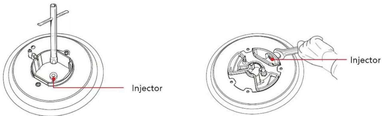
REPLACING THE COOKTOP BURNER INJECTORS
To convert the burners to suit a different gas type from that which it was set
(refer to the gas type label inside the warming compartment door), follow these steps:
-
Remove the pan supports (or trivets), remove the burner caps and the flame spreaders.
-
Using a wrench substitute the nozzle injectors with those most suitable for the type of gas for which the appliance is to use.
-
Adjust the minimum burner setting (refer to "Adjusting the minimum burner setting")
-
Refit the flame spreaders, the burner caps and the pan supports (trivets).
-
Fix the warning label (supplied with the conversion kit) stating that the freestanding oven has been converted for use with ULPG to the rear of the freestanding oven. Ensure that it is located in close proximity to the gas inlet connection.
The burners are designed so that no regulation of the primary air is required.
Auxiliary, Semi-rapid and Rapid Burners Wok Burners
Dual Burners
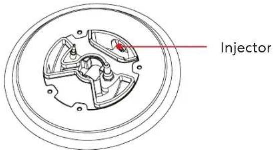
ADJUSTING THE MINIMUM BURNER SETTINGS
Adjusting the cooktop burner minimums
The flame has been regulated by the factory. When the injectors have been replaced or there are special mains pressure conditions, it may be necessary to regulate the minimum flame again. Check whether the flame spreads to all burner ports when the burner is lit with the gas tap set to the minimum position.
- If some ports do not light, increase the minimum gas rate setting.
- Check whether the burner remains lit even when the gas tap is turned quickly from the maximum to the minimum position.
- If the burner does not remain lit, increase the minimum gas rate setting.
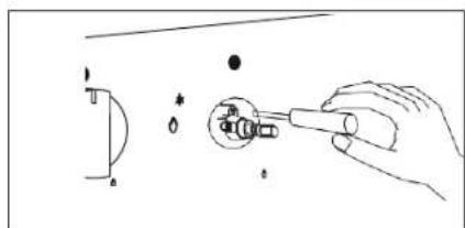
natural_image
Illustration of a hand using a tool to adjust a mechanical component (no text or symbols present)To regulate the flame follow these instructions:
Auxiliary, Rapid, Semi-Rapid, Triple-ring Wok Burners
- Light the burner.
- Set the gas valve to LO (minimum rate).
- Remove the knob.
- With a thin screwdriver, turn the regulation screw inside the tap rod until adjustment is correct.

Regulation screw (Auxiliary, Rapid, Semi-Rapid, Triple-ring and Single Wok burners)
Lubrication of the gas valves
- If a gas valve becomes stiff, it is necessary to dismantle it carefully and clean it with petroleum spirit.
- Specialist high temperature resistant grease should be used to lubricate the valve before replacing.
- This must be carried out by an authorised person or service agent. Please call our After Sales Service team on 1300 11 HELP (4357) to arrange one.
Technical Specifications
Below outlines the technical specifications for your Sôlt Freestanding Cooker.
| Model GGSUC908S.1 | |
| Size 895 × 595 | × 858–918 (W × D × H mm) |
| Weight (Gross/Net) | 93.0kg / 74.2kg |
| Maximum Power | 2940W |
| Gross Capacity | 121L (109L usable) |
Purchase Details
For future reference, please record the following information which can be found on the rating plate and the date of purchase which can be found on your sales invoice.
STORE DETAILS
STORE NAME
ADDRESS |
TELEPHONE | PURCHASE DATE
PRODUCT DETAILS
MODEL NO.
SERIAL NO.
Attach your receipt to this page

Warranty Information
WARRANTY TERMS & CONDITIONS OVENS (FREESTANDING COOKERS)
This document sets out the terms and conditions of the product warranties for Residentia Group Appliances. It is an important document. Please keep it with your proof of purchase documents in a safe place for future reference should you require service for your Appliance.
1. IN THIS WARRANTY
(a) ‘acceptable quality’ as referred to in clause 10 of this warranty has the same meaning referred to in the ACL;
(b) 'ACL' means Trade Practices Amendment (Australian Consumer Law) Act (No.2) 2010;
(c) 'Appliance' means any Residential Group product purchased by you accompanied by this document;
(d) 'ASR' means Residentia Group authorised service representative;
(e) 'Residentia Group' means Residentia Group Pty Ltd of 165 Barkly Ave, Burnley VIC 3121, ACN 600 546 656 in respect of Appliances purchased in Australia;
(f) 'major failure' as referred to in clause 10 of this warranty has the same meaning referred to in the ACL and includes a situation when an Appliance cannot be repaired or it is uneconomic for Residential Group, at its discretion, to repair an Appliance during the Warranty Period;
(g) 'Warranty Period' means:
(i) where the Appliance is used for personal, domestic or household use (i.e. normal single family use) as set out in the instruction manual, the Appliance is warranted against manufacturing defects for 24 months, following the date of original purchase of the Appliance;
(h) 'you' means the purchaser of the Appliance not having purchased the Appliance for re-sale, and 'your' has a corresponding meaning.
2. This warranty only applies to Appliances purchased and used in Australia and is in addition to (and does not exclude, restrict, or modify in any way) any non-excludable statutory warranties in Australia.
3. During the Warranty Period Residentia Group or its ASR will, at no extra charge if your Appliance is readily accessible for service, without special equipment and subject to these terms and conditions, repair or replace any parts which it considers to be defective. Residentia Group or its ASR may use remanufactured parts to repair your Appliance. You agree that any replaced Appliances or parts become the property of Residentia Group. This warranty does not apply to light globes, batteries, seals, filters or similar perishable parts.
4. Parts and Appliances not supplied by Residential Group are not covered by this warranty.
- You will bear the cost of transportation, travel and delivery of the Appliance to and from Residentia Group or its ASR. If you reside outside of the service area, you will bear the cost of:
(a) travel of an authorised representative;
(b) transportation and delivery of the Appliance to and from Residentia Group or its ASR, in all instances, unless the Appliance is transported by Residentia Group or its ASR, the Appliance is transported at the owner's cost and risk while in transit to and from Residentia Group or its ASR.
-
Proof of purchase is required before you can make a claim under this warranty.
-
You may not make a claim under this warranty unless the defect claimed is due to faulty or defective parts or workmanship. Residentia Group is not liable in the following situations (which are not exhaustive):
(a) the Appliance is damaged by:
(i) accident
(ii) misuse or abuse, including failure to properly maintain or service
(iii) normal wear and tear
(iv) power surges, electrical storm damage or incorrect power supply
(v) incomplete or improper installation
(vi) incorrect, improper or inappropriate operation
(vii) insect or vermin infestation
(viii) failure to comply with any additional instructions supplied with the Appliance;
(b) the Appliance is modified without authority from Residential Group in writing;
(c) the Appliance's serial number or warranty seal has been removed or defaced;
(d) the Appliance was serviced or repaired by anyone other than Residentia Group, an authorised repairer or ASR.
-
This warranty, the contract to which it relates and the relationship between you and Residentia Group are governed by the law applicable where the Appliance was purchased.
-
To the extent permitted by law, Residentia Group excludes all warranties and liabilities (other than as contained in this document) including liability for any loss or damage whether direct or indirect arising from your purchase, use or non use of the Appliance.
-
For Appliances and services provided by Residentia Group in Australia, the Appliances come with a guarantee by Residentia Group that cannot be excluded under the Australian Consumer Law. You are entitled to a replacement or refund for a major failure and for compensation for any other reasonably foreseeable loss or damage. You are also entitled to have the Appliance repaired or replaced if the Appliance fails to be of acceptable quality and the failure does not amount to a major failure. The benefits to you given by this warranty are in addition to your other rights and remedies under a law in relation to the Appliances or services to which the warranty relates.
- At all times during the Warranty Period, Residentia Group shall, at its discretion, determine whether repair, replacement or refund will apply if an Appliance has a valid warranty claim applicable to it.
- Missing parts are not covered by warranty. Residential Group reserves the right to assess each request for missing parts in a case by case basis. Any parts that are not reported missing in the first week after purchase will not provide free of charge.
- To enquire about claiming under this warranty, please follow these steps:
(a) carefully check the operating instructions, user manual and the terms of this warranty;
(b) have the model and serial number of the Appliance available;
(c) have the proof of purchase (e.g. an invoice) available;
(d) telephone the numbers shown below. - You accept that if you make a warranty claim, Residential Group and its ASR may exchange information in relation to you to enable Residential Group to meet its obligations under this warranty.
IMPORTANT
Before calling for service, please ensure that the steps in point 13 have been followed.
Telephone contacts
▶ Service: Please call 1300 11 HELP (4357)
T. 1300 11 4357
E. support@residentiagroup.com.au
www.solt.house
- Welcome Congratulations on purchasing your new Freestanding Cooker! The Sôlt brand is proudly distributed within Australia by Residentia Group Pty Ltd.
- Residentia Group
- Sôlt
- Contents 2 Welcome
- Customer Care
- General Safety Instructions
- IMPORTANT SAFETY INSTRUCTIONS
- WARNING! Installation Electrical Shock Hazard
- IMPORTANT INSTALLATION ADVICE
- GENERAL USAGE CONDITIONS AND RESTRICTIONS
- OVEN-SPECIFIC SAFETY ADVICE
- COOKTOP-SPECIFIC SAFETY ADVICE
- General Safety Instructions (Continued)
- CAUTION: Hot!
- Do not touch hot surfaces:
- DECLARATION OF CONFORMITY
- OTHER REPAIRS OR SERVICE INSPECTIONS
- WARNING:
- RESPONSIBLE DISPOSAL
- Your Freestanding Cooker
- Your Freestanding Cooker (Continued)
- COOKING FUNCTIONS
- Light
- Defrost
- Bake (also known as Conventional)
- Fan Assisted Multi-level Oven
- Fan Forced
- Lower Element
- Grill
- Full Grill
- Fan Assisted Grill
- USING THE GRILL
- CLOCK/PROGRAMMER
- Set alarm
- Duration setting
- Time function
- Other notification
- Operating Instructions
- FIRST USE
- IMPORTANT! Before first use:
- Position your shelves
- Your Oven
- Conditioning the oven
- Note:
- Important!
- DESCRIPTION OF SYMBOLS
- ACCESSORIES
- Operating Instructions (Continued)
- For correct use of the cooktop
- Cooking Guidelines
- Baking
- Roasting
- Grilling
- Reheating food
- Cleaning & Maintenance
- Cleaning Do's
- Cleaning Don'ts
- Cleaning & Maintenance (Continued)
- Removing the oven door
- Removing the chrome side racks
- Cleaning the burner parts
- Replacing the burner parts
- Check that:
- If a burner does not light
- Cleaning the ignitor & probe
- Replacing an oven bulb
- Important! Failure to disconnect the cooker from the power supply may result in death or electrical shock.
- Installation Instructions
- PRIOR TO INSTALLATION
- Unpacking and product handling
- Product Dimensions
- Installation Instructions (Continued)
- Important Notes:
- Compliance
- Rear and Side Clearances
- Installing the cooker on a plinth
- LEVELLING THE FEET
- FITTING THE SAFETY STABILISER CHAIN
- MAKE SURE THAT THE ANTI-TILTING CHAINS ARE TIGHT WHEN ANCHORED TO PREVENT THE APPLIANCE
- INCORRECT CHAIN INSTALLATION
- WARNING: Accidental Tipping
- CORRECT CHAIN INSTALLATION
- VENTILATION REQUIREMENTS
- FITTING THE ADJUSTABLE FEET
- LEVELLING THE FREESTANDING OVEN
- MOVING YOUR FREESTANDING OVEN
- Electrical Connection
- IMPORTANT
- WARNING: THIS APPLIANCE MUST BE EARTHED.
- REPLACING THE POWER CORD
- CONNECTION OF THE POWER SUPPLY CABLE
- Gas Connection
- INSTALLATION WITH A FLEXIBLE HOSE ASSEMBLY
- GAS CONNECTION SPECIFICATION
- Natural Gas
- ULPG
- Gas Connection (Continued)
- LP/Propane
- LEAK TESTING
- FLAME TESTING
- CONVERSION TO ULPG
- REPLACING THE COOKTOP BURNER INJECTORS
- ADJUSTING THE MINIMUM BURNER SETTINGS
- Adjusting the cooktop burner minimums
- To regulate the flame follow these instructions:
- Lubrication of the gas valves
- Technical Specifications
- Purchase Details
- STORE DETAILS
- PRODUCT DETAILS
- Attach your receipt to this page
- Warranty Information
- WARRANTY TERMS & CONDITIONS OVENS (FREESTANDING COOKERS)
- IN THIS WARRANTY
Brand : Sôlt
Model : GGSUC908S.1
Category : Cooker