
District Heating Substations - District Heating Substations DANFOSS - Free user manual and instructions
Find the device manual for free District Heating Substations DANFOSS in PDF.


| Product Type | District Heating Substation (indirect compact substation) |
| Applications | Indirect heating/cooling, domestic hot water (DHW) production, and other water-based heating systems |
| Power Supply | 230 V AC, 50-60 Hz (typical; verify nameplate) |
| Maximum Operating Temperature | Up to 130°C (primary side; secondary side up to 100°C for heating, 95°C for DHW) |
| Maximum Operating Pressure | Primary: 16 bar; Secondary heating: 6 bar; Secondary DHW: 10 bar (PN class; refer to nameplate) |
| Heat Exchanger Type | Brazed plate heat exchanger (copper brazed) |
| Controller Type | Danfoss ECL310 (with weather compensation, remote access, data logging) |
| Safety Features | Safety valves, strainers, expansion vessel, temperature and pressure limiters; emergency stop not integrated |
| Maintenance Interval | Every 2 months (visual inspection, parameter check); every 6 months (functional test of safety valve, electrical components); every 12 months (full functional check, heat exchanger inspection) |
| Spare Parts | Only original Danfoss spare parts |
| CE Compliance | CE marked according to PED 2014/68/EU |
| Packaging | Wood, cardboard, plastics; transport packaging can be returned to Danfoss |
| Installation Requirements | Qualified personnel only; primary connection by district heating company; electrical connection by certified electrician |
| Commissioning | By manufacturer or authorized partner; secondary side first, then primary side; system must be filled, vented, and rinsed |
| Troubleshooting | Common issues: low/high temperature, leaks, noise, no heat; refer to manual for detailed solutions |
Frequently Asked Questions - District Heating Substations DANFOSS
User questions about District Heating Substations DANFOSS
0 question about this device. Answer the ones you know or ask your own.
Ask a new question about this device
Download the instructions for your District Heating Substations in PDF format for free! Find your manual District Heating Substations - DANFOSS and take your electronic device back in hand. On this page are published all the documents necessary for the use of your device. District Heating Substations by DANFOSS.
USER MANUAL District Heating Substations DANFOSS
District Heating Substations
suitable for indirect heating / cooling, dhw production and other water based heating systems
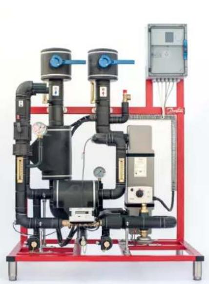
natural_image
Industrial piping and control unit with red frame and digital display (no visible text or symbols)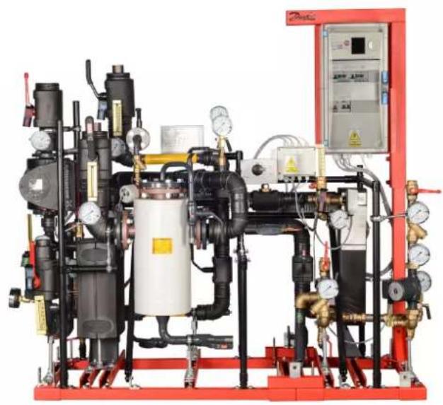
natural_image
Industrial equipment setup with hydraulic cylinders, valves, and control panel (no visible text or symbols)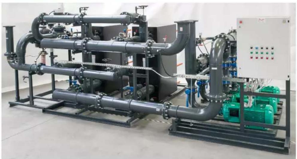
natural_image
Industrial piping and control panel setup in a factory setting (no visible text or symbols)Always keep the instruction manual readily available near the device.
Read the instruction manual before installation!
In case of wrong installation
Danfoss could change warranty terms!
Caution!
Before putting the device into service,
check if it is undamaged and in perfect operating condition.
Original operating instructions
Table of contents
1.0 General information ....3
1.1 Information on installation and operating instruction manual ....3
1.2 Other applicable documents .... 3
1.3 Explanation of symbols .... 3
1.4 Liability and warranty....3
1.5 Copyright 4
1.6 Spare parts ....4
1.7 Dismantling....4
1.8 Disposal 4
2.0 Safety 5
2.1 General information ....5
2.2 Responsibility of the operator ....5
2.3 Intended use 5
2.4 Possible misuse ....5
2.5 Safety work 5
2.6 Personal protective equipment 6
2.7 Possible hazards of the device 6
2.8 Emergency stop switch 7
2.9 Operating personnel 7
2.10 Actions in the event of danger or accidents....7
2.11 Residual hazards / hazard analysis ....8
3.0 Technical data 9
3.1 Technical and main system data 9
3.1.1 CE label 9
3.1.2 Dimensions and packaging 9
3.2 Symbols used in circuit diagrams 10
4.0 Function and configuration 10
4.1 Function 10
4.2 DSE FLEX configuration possibilities 11
5.0 Transport, packaging and storage 12
5.1 Transport of pallets by forklift 12
5.2 Transport inspection 12
5.3 Packaging 13
5.4 Storage 13
6.0 Installation 13
6.1 Installation preparation 14
6.1.1 Primary connection 14
6.1.2 Secondary connection 14
6.1.3 Electrical connection 14
6.2 Draining station 17
7.0 Commissioning 18
7.1 Requirements for commissioning 18
7.2 Secondary side commissioning 18
7.3 Primary-side commissioning 18
7.4 Requirements for commissioning 19
7.5 Fault and Shutdown 19
7.6 Commissioning after a failure or malfunctioning 19
8.0 Operation 19
8.1 Switching on 19
8.2 Switching off 19
8.3 Restarting after substation shutdown 19
8.4 Service/clean-strainer 20
8.5 Service/disassembly and replacement - heat exchanger 21
8.6 Service/Check - Safety valve and expansion vessel 21
9.0 Maintenance 22
9.1 Safety warning 22
9.2 Maintenance plan (recommendations) 22
9.3 Heat exchanger maintenance 23
9.4 Maintenance validation 23
10.0 Troubleshooting 24
10.1 Safety 27
11.0 Spare parts 27
12.0 Index 28
1.0 General information
1.1 Information on installation and operating instruction manual
This Instruction Manual describes installation, operation and maintenance of the system. Compliance with all specified safety instructions and operating instructions is a prerequisite for safe system operation and handling. In addition, the local accident prevention regulations and specific / general safety regulations, applicable to the area where system is installed must be observed. The operating instructions are part of the product and must be kept accessible for installation, operating, maintenance and cleaning personnel at all times in the immediate vicinity of the system's operating area.
1.2 Other applicable documents
Unless stated otherwise, the individual components of the system are modules purchased from other manufacturers. All components used in the system have been subjected to risk assessments by their manufacturers. The conformity of the design with the applicable European and national regulations has been declared by the manufacturers of the components. The manufacturers' declarations of conformity, as well as the operating, maintenance and repair instructions for the individual system components, are inseparable parts of the system documentation.
1.3 Explanation of symbols
Important safety and device-related instructions in this operating manual are marked by warning symbols. The instructions must be followed in order to avoid accidents, personal injury and material damage.

WARNING!
This symbol identifies hazards that may result in adverse health effects, injuries, permanent bodily injury or death. Ensure compliance with the instruction manual on work safety and take extra care in these cases.

WARNING!
Electrical hazard. This symbol is alert for safety hazards involving electricity. Failure to observe the safety instructions may result in serious injury or death. Work required on electrical parts of the system can only be carried out by a qualified electrician.
1.4 Liability and warranty
All information and instructions in this operating manual have been compiled taking into account the applicable regulations, accepted standards of good engineering practice, and our many years of expertise and experience. In the case of special versions, use of additional order options or due to the latest technical changes, the actual scope of delivery may differ from the explanations and drawings in this document. If you have any questions, please contact the manufacturer. We reserve the right to make technical changes to the product as part of improving the performance characteristics and product development. Parts such as tools subject to wear in the use of the device and/or normal wear and tear, as well as auxiliary supplies and consumables such as greases, oils or cleaning agents, are not covered by the warranty.
For presentation purpose of the described situations, the illustrations in this manual are not necessarily to scale and may differ slightly from the actual design of the system.
In addition to this operating instruction manual, the operating instructions for the installed components apply. The information contained therein – in particular safety instructions – must be observed at all times.
The instructions for safety, assembly and installation, operation, maintenance, disassembly and disposal of the components contained in the manufacturer's documents must be followed by the system's operating personnel unconditionally.

CAUTION!
This symbol indicates instructions, the non-observance of which may result in damage, malfunctions and/or system failure.

NOTE!
This symbol highlights tips and information that must be observed for effective and trouble-free operation of the system.
Additionally, the obligations agreed in the delivery contract, the general terms and conditions of business, and the delivery conditions of the manufacturer and applicable statutory regulations at the time of the conclusion of the contract apply.

NOTE
These installation and operating instruction manual must be read carefully before starting work on and with the device, particularly before commissioning. The manufacturer accepts no liability for damage or malfunctions resulting from non-compliance with the installation and operating instructions.
1.5 Copyright
The installation and operating instruction manual are to be treated as confidential. They are intended solely for persons working on and with the system. Transfer of the operating instructions to third parties without the written consent of the manufacturer is not permitted. If necessary, contact the manufacturer.
Reproduction in any form – even in extracts – as well as utilization and/or communication of the content are not permitted without the written approval of the manufacturer. Violations will incur damages. The right to further claims remains reserved.
1.6 Spare parts
Only use original spare parts of the manufacturer.
If non-approved spare parts are used, all warranty, service, damage and liability claims against the manufacturer or its agents, dealers and representatives are forfeited.
1.7 Dismantling
For disposal or scrapping, clean and dismantle the device in accordance with applicable health and safety and environmental regulations.
Before starting the dismantling:
- Switch off the device and secure it against being switched on again.
- Physically disconnect the all energy and/or power sources from the device and discharge stored residual energy in accordance with regulations.
- Remove operating and auxiliary materials and other processing materials in an environmentally friendly manner.

NOTE!
The content, text, illustrations, images and other representations are protected by copyright and are subject to additional industrial property rights. Any improper use may be subject of legal action.

CAUTION!
Incorrect or faulty replacement parts can lead to damage, malfunctions or total failure of the system.

WARNING!
Risk of injury! Stored residual energy, sharp edges, points and corners on and in the device or on the required tools can cause injuries. All work during dismantling of the device may therefore only be carried out by qualified personnel.

WARNING!
Not drinking water!
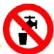
Domestic water in parts of the system that are not used for a long time may no longer be suitable for drinking. Prevent such use; drain the system parts and dispose of the water.
1.8 Disposal
If no return or disposal agreement has been made, dispose of disassembled parts after proper dismantling as follows:
- Scrap metallic materials.
• Recycle plastic materials. - Dispose of other components, sorted according to the type of material.
- Dispose of residual media properly. When introducing additives (e.g. glycol, etc.), the applicable regulations must be observed.
Remove used materials such as greases, oils, preservatives and cleaning agents from the device according to type and in an environmentally responsible manner. Use suitable collection and storage containers approved for the respective operating fluids. Label containers with contents, fill level and date and store them protected against misuse until final disposal.

WARNING!
Electronic waste, electronic components, lubricants and other auxiliary materials are subject to special waste treatment and may only be disposed of by authorized specialist companies!
2.0 Safety
This section provides an overview of all important safety aspects for optimum protection of the personnel and for the safe and trouble-free operation of the device. In addition, the individual subsections contain specific safety instructions, marked with symbols, to avert immediate dangers.
2.1 General information
The device is built in accordance with applicable and accepted rules of good practice at the time of its development and production and is considered safe to operate. However, the device may pose a hazard if it is used by improperly trained personnel or is used improperly or not as intended. Every person who is tasked with working on or with the device must therefore have read and understood the operating instructions before starting work. It is recommended that the operator demonstrably confirms the personnel's knowledge of the operating instructions. Modifications of any kind, as well as attachments or conversions on the device, are prohibited. All safety, warning and operating instructions on the device must always be kept in a legible state. Damaged signs or stickers must be replaced immediately. Specified setting values or ranges must be strictly adhered to.
2.2 Responsibility of the operator
- Operating instructions must always be stored within the immediate vicinity of the substation and must be accessible at all times for installation, operation and maintenance and to cleaning staff.
- Operate the substation only if it is in a proper technical and safe operating condition.
- Check that safety devices are always kept freely accessible test them regularly.
Information about industrial safety is based on the European Union regulations valid at the time of manufacture of the substation. The operator is obliged throughout the entire lifetime of the substation to conform to those safety actions designated in the current rules and regulations and to comply with those in new regulations. Outside of the European Union, the safety laws, local rules and regulations applicable to the location where the substation operates must be followed.
2.3 Intended use
The operational safety of the device is only assured if it is used as intended in accordance with the instructions in the operating manual. The system serves to provide heat energy from the supply grid of an energy company or other heat generation facility (e.g. boiler) by transferring heat to a customer's in-house system. Proper use also includes correct compliance with the installation, operating, maintenance and cleaning instructions.
2.4 Possible misuse

WARNING. Hazard from improper use!
Any use of the substation apart from its intended use may lead to dangerous situations.
2.5 Safety work
Hazards to persons and / or the system can be prevented by following the safety at work instructions.

NOTE
For modification and extension activities, always consult the substation manufacturer.
In addition to the safety instructions in this manual, and for substation safety in general, accident prevention and environmental protection regulations must be observed and followed. The operator and authorised personnel are responsible for the trouble-free operation of the substation, as well as for the clear definition of responsibilities for installation, operation, maintenance and cleaning of the substation. There must be no deviation from the information in the operating instructions!
The operator shall also ensure that:
- Any further risks are identified in an assessment of risks arising from the special working conditions at the operations site.
- That any additional work and safety instructions resulting from the risk assessment of activities performed on the substation are described in a standard operating procedure (SOP).
Always follow local regulations as well as any existing ordinances on industrial safety and health (e.g. in Germany: BetrSichV, BGBL I 2002, 3777).
Any other and/or different use of the device is prohibited and is considered improper. Claims of any kind against the manufacturer and/or its authorized representatives due to damage resulting from improper use of the device are excluded. The operator and/or the owner is solely liable for all damage resulting from improper use.
Therefore:
- Use the district heating transfer station only for its intended purpose and in accordance with the information provided in this document, particularly the limitations given in the technical data.
- Avoid any further or other use of the district heating transfer station.
- It is forbidden to change, upgrade or modify the design or individual components for the purpose of changing the station's range of usability or application.
2.6 Personal protective equipment
When working on and with the device personal protective equipment must be used in accordance to EU, national and local regulations, we strongly advice that you must always wear:

Protective clothing
Consisting of closely fitting workwear with low tear resistance, with closely fitting sleeves and no protruding parts. It is mainly used to protect against being caught by moving machine parts. Do not wear rings, necklaces or other jewelry.

Protective gloves
To protect hands from friction, abrasions, punctures or deeper injuries, as well as from contact with hot surfaces.
2.7 Possible hazards of the device
The substation has been subjected to a risk analysis based on the design and construction of the substation and in correspondence with the current state of technology. Nevertheless, risks remain! The substation can generate a hot stream of fluid or steam when e.g. a drain or air vent is opened.

WARNING! Risk of injury!
Danger from spraying liquids under high pressure. Always wear personal protective equipment when working on the device.
The substation operates with high electrical voltages of up to 400 V and currents of up to 25 A.

WARNING! Electrical hazard!
The electrical energy can cause serious injuries. In the event of damage to the insulation or individual components, there is a danger to life.
- Before carrying out any maintenance, cleaning or repair work, switch off the main switch and secure it against being switched on again.
- Disconnect the device from the power supply for all work on the electrical system.
- Do not remove any safety devices or disable them by modifications.
The substation is supported by pneumatic components.

WARNING! Risk of injury!
Risk from liquids splashing under high pressure. Wear personal protective equipment for all operations carried out on the substation!

Safety goggles
To protect the eyes from flying objects and liquid splashes.

Safety footware
To protect against heavy falling parts and slipping on slippery surfaces.

Protective helmet
For protection against falling objects and flying parts and materials.
Therefore:
- Depressurise before starting any work on the substation.
- Do not remove or alter any safety devices or put out of service.
- Do not change the default settings from the values or beyond the tolerance ranges specified in the operating manual
The substation has sharp edges and corners.

WARNING! Risk of injury!
Sharp-edged housing parts and sharp corners can cause skin abrasions. Wear protective gloves when working on the device.

WARNING! Risk of burning!
Hot surfaces can cause severe burn injuries. When working on the device, always wear protective gloves. The device operates at a maximum temperature as indicated on the label.
Components inside of the station can contain automatically moving parts (pumps, actuators, etc.). The devices can be very heavy.


WARNING! Risk of crushing!
Heavy objects can cause crushing during transport, even with lifting equipment. The device may contain electrically powered moving components (motors, gearboxes) that can cause crushing when touched during operation. When working on the device, always switch off the power and wear protective clothing.
2.8 Emergency stop switch
An emergency stop switch is not integrated in the device. The operator must ensure that emergency stop switches are installed in accordance with the applicable accident prevention regulations, if required by law.
2.9 Operating personnel
The device may only be operated and maintained by authorized, trained and instructed personnel. This personnel must have received specific instruction on the hazards that may occur.
An instructed person is someone who has been instructed and, if necessary, trained on the tasks entrusted to them and the possible hazards arising from improper conduct, and has been instructed on the necessary protective devices and protective measures.
Qualified personnel are those who, on the basis of their professional training, knowledge and experience, as well as knowledge of the relevant provisions, are able to assess the work assigned to them and recognize possible hazards.
If the personnel do not have the necessary knowledge, they must be trained. The responsibilities for operation and maintenance must be clearly defined and adhered to, so that there is no unclear allocation of responsibilities with regard to safety.
The device should only be operated and maintained by persons who can be expected to perform their work in correct and responsible manner. Any operation which affects the safety of persons, the environment or the device is to be avoided. Persons who are under the influence of drugs, alcohol or medication that affects their ability to respond should not perform any work on or with the device.
When selecting personnel, minimum age requirements in the country's youth employment legislation must be observed and, where relevant, applicable professional regulations. The operator must ensure that no unauthorized persons work on or with the device. Unauthorized persons, such as visitors, etc., must not come into contact with the device. They must maintain a reasonable safety distance.
The person using the device must immediately notify the operator of any changes to the device that affect safety.
2.10 Actions in the event of danger or accidents
In case of danger or accidents, the device should be switched off immediately by activating an emergency stop switch. This can also be done by opening a safety door or protective screen provided with safety switches, which triggers the emergency stop function when opened.
Safety devices with emergency stop function are only to be operated in emergency situations.
Safety devices must not be used for normal shutdown of the device. Always be prepared for accidents or fires. Keep first aid equipment (first aid kit, eyewash bottle, etc.) and fire extinguishers within easy reach, EU and local regulations apply.
Personnel must be familiar with the handling and location of safety, accident reporting means, first aid and rescue equipment. This ensures protection against hazards and the best possible assistance in the event of accidents.
2.11 Residual hazards / hazard analysis
| Risk place Risk type | Protective aim Measure | ||
| Shut-off valves and fittings in the station | Crushing during manual operation | Manual operation of the shut-off valves and fittings must be safe | Due to construction, provide enough space for ergonomic operation |
| Piping and components in the station | Burning when touched Safe | contact at the station | Thermal insulation of pipes and components, signs at the station, warnings in the operating instructions |
| Entire station Electric sh | ock Safe contact with the station | Fulfilment of contact protection | |
| Entire station | Splashing of liquids and/or steam at high pressure | Controlled reduction of excess pressure in case of fault | Protection according to local standards or legal regulations (e.g. DIN 4747 T1 or DIN EN 12828) |
| Entire station | Overheating the station or transmitting heat to a connected system at a temperature above what is permissible | Turning off the heat supply in case of failure | Protection according to local standards or legal regulations (e.g. DIN 4747 T1 or DIN EN 12828) |
During operation, residual risk can be limited to the following alphabetic values according to the Suva (Assessment and Reduction of risks from machines) risk assessment: B5/C4/D3/E2. The residual potential for danger arises from failure to comply with the above instructions. The assembly has been manufactured according to the explicit specifications of the customer, who is responsible for compliance with the parameters specified and the selection of qualified operating personnel.
The substation is equipped with the following warning on which the key residual risks are point out again:
Operation of this substation is permitted only by trained personnel after detailed study of the enclosed documentation. The system must be filled and completely vented before commissioning. Do not exceed the maximum allowable working pressure or maximum allowable operating temperature specified on the label. Any use other than the proper use is prohibited.

Risk of burns from touching or from the release of hot media (water/steam). Avoid touching the substation or wear suitable protective clothing!
Risk of crushing during assembly and operation.

Risk of electric shock. Check that the substation is disconnected before working with the electrical system.
All flange and threaded connections, fittings, electrical clamps and screw connections must be checked and tightened as necessary before filling or commissioning. Run pumps only when filled with water (no dry run!)
Before starting up the substation properly install the following (unless fully assembled in factory):
- Safety valve, drain and air vent according to EN12828 or EN806, unless local standards are available.
- Strainer in the primary flow and secondary return pipeline
- Equipotential bonding according to IEC60364-4-41:2005 (grounding / protective conductor / potential equalisation), unless local standards are available (e.g. DIN VDE 0100:540:2012-06)
3.0 Technical data
3.1 Technical and main system data
The main system data can be found on the label as well as the documents contained in the systems (title page, wiring diagram, data sheet).
3.1.1 CE label
The CE label is attached to the substation. It contains the following information:
- Manufacturer
- Serial no.
• Production date (year / calendar week) - Substation code / Type (Name)
- Applications
• Category according to PED directive
• Power supply voltage - PN class
• Minimum and maximum operating temperatures
• Maximum allowed pressure by maximum operating temperature - Capacity
• Temperature programme - Heat exchanger type
• Volumetric flow
• Pressure drop inside heat exchanger
3.1.2 Dimensions and packaging
The range of tailored product dimensions and weights can be found in the manual.
The DSE is manufactured upon customer request; its dimensions and weight may vary depending on accessories selected. Details of dimensions and weight are available before delivery to ensure trouble-free transport and installation of the substation.
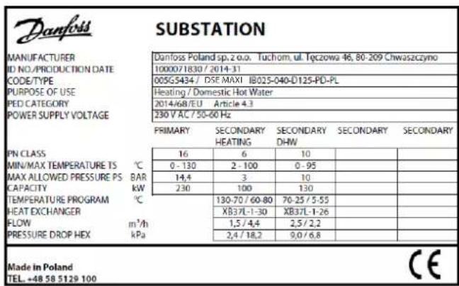
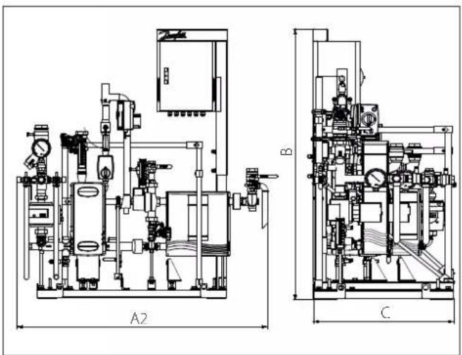
Figure 1: Danfoss Substations external dimensions
3.2 Symbols used in circuit diagrams
 | Shut-off valve |  | Sensor ( in general: direct immersion, immersion) |  . . | Pump |
 | Balancing valve |  | Surface temperature sensor |  | Control valve (general) |
 | Strainers (filters) |  | Safety thermostat |  | Combi valve |
 | Check valve |  | Safety pressure, maximum |  | 3-way control valve (general) |
 | Expansion valve |  | Pressure transmitter |  | Flow controller |
 | Electromagnetic valve |  | Heat meter |  | Differential pressure controller |
| [8SY3] | Thermometer |  | Flow meter |  | Differential pressure controller/ flow control |
 | Manometer |  | Safety valve |  | Differentia pressure controller flow limit |
  | Tube and shell heat exchanger |   | Plate heat exchanger |  | Air - vent |
 | Drain valve | ||||
 | Domestic Cold Water |  | Heating Supply |  | District Heating Supply |
 | Domestic Hot Water |  | Heating Return |  | District Heating Return |
 | Circulation |
4.0 Function and configuration
4.1 Function
The substation is an indirect compact substation, where heat transfer from the district heating or cooling network to a secondary installation is realised via heat exchangers. This solution ensures hydraulic system separation.
The basic idea of heat transfer in a compact substation is connecting the primary side of the piping to the district heating company's network, which supplies hot water within the appropriate parameters (such as for pressure and temperature), and the secondary piping to the customer's installation on the other side. Network parameters may vary depending on the season and may be higher during the winter season and lower during the warmer months. Primary medium flow normally through shut-off valve and strainer In addition for pressure and temperature measurements, usually pressure gauge and thermometer are assembled, if it is needed according to the specification of District Heating Utility on primary flow and/or return pipe. Cooled heating water flows back through the primary return pipeline to the district heating network.
In a District Cooling system the chilled water is (lower temperature for example 7 deg. C) is entering the heat exchanger through the primary flow pipe and warmed water (for example 12 deg. C) it flows back through the primary return pipe to the District Cooling network.
In the secondary circuit circulation pump transfers heated water to the heating surfaces of other installations (e.g. ventilation equipment, drinking water or heating installations, etc.). If a controller with weather compensation is installed at the substation, it has the following essential functions:
• Measures flow temperature on the secondary side and outdoor temperature
• Changes the stroke of the control valve on the primary side so that it conforms to the required secondary temperature
- Limits the return temperature on the primary side to a value preset in the controller
- Switches the secondary side circulating pump(s) on and off as necessary and ensures frost protection
If required, special functions are available according to needs and designs. Refer to the instruction manual of the controller manufacturer. All systems are offered upon request and manufactured in keeping with the customer's special operating conditions.
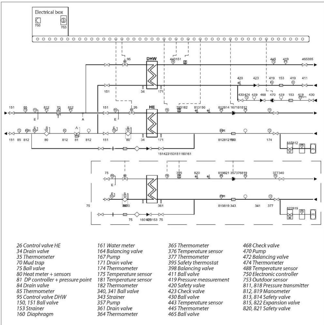
Due to the many different product variations, the circuit diagram may differ from that presented below.
4.2 Danfoss Substation configuration possibilities
The substation can be used for various applications such as cooling/heating, domestic hot water and / or other water based heating system. Due to its flexibility, we have inserted in this document only an example diagram, for the actual application please refer to the manual. This is based on customer requests and the needed application(s). The construction allows easy access to all components for maintenance and servicing purposes. Heat transfer between the district heating network and the building installation is achieved by way of a heat exchanger, which ensures better heat transfer, higher energy efficiency and reduced pressure loss.
In addition to the standard controller functions, the ECL310 offers easy remote access via an internet page with data logging possibilities and energy optimization functions such as weather compensation and auto-tuning (adaptive settings for domestic hot water parameters). Refer to the manual for the actual controller and application key.
By use of the Danfoss dimensioning program you can find out if the application you need fits the Danfoss substation.
other
| Component | Value | |-----------|-------| | Electrical box | 750 | | HE | 95 | | DHW | 443151 | | DHW | 171 | | HE | 385182 | | HE | 813150 | | HE | 171 | | Control valve HE | 161 | | Water meter | 365 | | Temperature sensor | 376 | | Check valve | 468 | | Drain valve | 164 | | Pump | 377 | | Turbine sensor | 395 | | Temperature sensor | 398 | | Safety sensor | 411 | | Turbine valve | 819821 | | Temperature sensor | 819819 | | Electronic controller | 377 | | Drain valve | 182 | | Thermometer | 340 | | Ball valve | 343 | | Pressure measurement | 420 | | Manometer | 812 | | Safety valve | 813 | | Expansion valve | 815 | | Diaphragm | 160 | The diagram shows connections between labeled components and their associated sensors and valves.Figure 3: DSE FLEX configuration
5.0 Transport, packaging and storage
Follow general safety rules during transport:
- Adapt transportation to local conditions
- Use only approved lifting gear and lifting equipment with adequate load capacity
- Only attach the substation to suitable anchor points and not to protruding machine parts or any component's eylet or hole. Ensure the secure fit of the slings!
- Ropes and belts must be equipped with a safety hook. Do not use damaged or frayed cables. Do not fasten ropes or straps to sharp edges or corners and do not knot or twist. Always consider the centre of gravity before handling
- Never lift, pan or lower loads over people
• Always transport the substation with the utmost care and caution
- During vessel transport especially bear in mind that: insulation must not be damaged during transport or removed (especially when transporting over longer distances)
- Ensure suitable means of transport so that no deformation arises on connections or vessel
- Avoid direct contact with ferrous materials or surface destruction of stainless steel vessels
5.1 Transport of pallets by forklift
Packages mounted on pallets can be transported by forklift under the following conditions:
- The forklift must be designated according to the weight of the handling units
- Operator must be authorised (licensed) to operate the forklift
Procedure:
- Drive the forklift with the forks between or under the tie bars of the pallet
-
Drive the forks far enough to protrude from the opposite side of the pallet
-
Make sure that the centre of gravity is between the forks and cannot tilt
-
Lift the package and start transport
Follow safety rules:
- Use only approved lifting gear and lifting equipment with adequate load capacity
- Only attach the substation to suitable anchor points and not to protruding machine parts or eyelet components. Ensure the secure fit of the slings!
- Ropes and belts must be equipped with a safety hook. Do not use damaged or frayed cables. Do not fasten ropes or straps to sharp edges and corners and do not knot or twist. Always consider the centre of gravity before handling
- Never lift, pan or lower loads over people
• Always transport the substation with the utmost care and caution
5.2 Transport inspection
Immediately after delivery check for completeness and any transportation damage. In case of externally visible transport damage, do not accept delivery or accept only conditionally. Note the extent of damage on the transport documents / bill of delivery. Initiate a complaint. Claim defects that are not visible immediately after detecting, as claims for damages can be made only within the applicable complaint periods.

WARNING! Danger to life!
When lifting, panning and lowering, there is a risk of serious personal injury and damage from falling parts. Never stand under suspended loads!

WARNING! Danger to life!
When lifting, panning or lowering, there is a risk of serious personal injury and damage from falling parts. Never stand under suspended loads!
5.3 Packaging
Substations are delivered with different types of packaging. Packaging materials are primarily of wood, cardboard and plastics (foil, foams). Strapping is in addition. Packaging material may also include materials added to packages for moisture or frost protection (e.g. silica gel bags, antifreeze, etc.). If no agreement has been made regarding the return of packaging material, the packaging material remains with the customer.
Our transport packaging can be returned to Danfoss, at the manufacturing site. Please refer to the label.
5.4 Storage
After packages have been unloaded they must be stored until assembly in accordance with the attached shipping marks. Machine parts and accessories packaged in separate boxes must not be unpacked.
For storage, the following rules apply:
• Dry storage. Relative humidity: up to 60%
- Ensure that packages are not stored outdoors. In addition, ensure that the storage room floor is dry during storage
- Keep out of direct sunlight. Optimal storage temperature 15 to 25 C°
- Keep dust-free
- Avoid mechanical vibrations and damage
- For long-term storage of more than three months, conservation activities should be taken In severe weather conditions, conservation must be renewed as necessary
6.0 Installation

WARNING! Risk of injury!
Improper installation and assembly can result in serious injury and / or property damage. Installation and assembly work may be performed only by qualified personnel in compliance with safety regulations.
District heating transfer stations are usually completely pre-piped and wired installations on a painted steel frame. All parts and components are mounted or fixed to the frame. External substation connections are marked with easily understandable labels / stickers. Integrated adjustable feet are used to compensate for uneven ground.
Secure durability of ground based on total weight of equipment (including water content). Take care that each connection is stress-free after assembly; the substation cannot be used as a fixed point.

NOTE!
The use of pipe wrenches for nuts and bolts is not permitted. Only use a suitable spanner!

WARNING!
Unpaid delivered transport packaging will not be accepted by Danfoss.

Packaging materials must be utilised in an environmentally friendly way and in accordance with the relevant waste disposal regulations.
If substation parts or components must be removed due to limited space for transport (corridors, elevators, small doors etc.), ensure that they are reassembled exactly as they were in the original place.

NOTE!
The mechanical separation of substation components through sawing, cutting, etc. of cabling and / or frame parts and piping is not permitted.
Pipe connections and fitting connections can be prepared as:
- Welding ends
• Flanged connections acc. EN 1092 - Threaded connections acc. DIN 2999 (internal / external)
- Threaded connections acc. DIN 2993/ISO 228 (external)
6.1 Installation preparation
Substation installation should be carried out on a clean, flat surface. Stand-alone substations usually come with integrated adjustable feet, which can compensate for uneven ground. If not pre-assembled, these are supplied as loose components in an accessory pack and can be screwed into the appropriate nuts in the bottom area of the frame. Then adjust the station horizontally.
6.1.1 Primary connection
The primary connection must be made by qualified personnel in consultation with local / district heating supply companies if the installation is connected to such network. The primary supply and return must be connected to the designated devices or the substation shut-off valves.
The commissioning of primary side connections to the district heating network is usually done by the relevant local / district heating company.
- If substation is delivered (ordered) without a strainer on primary inlet site, make sure it is separately mounted before substation is connected to the network to protect all components from potential damage. If this requirement is not respected it may result in loss of warranty.
- After installation of substation to the network it is required to splash pipes between main strainer and substation to remove any potential particles.
6.1.2 Secondary connection
A specialised installation company connects the secondary installation to the substation's designated shut-off valve.
After installation of substation to the network it is required to splash pipes between main strainer and substation to remove any potential particles.
6.1.3 Electrical connection
Only a qualified electrician approved by a responsible electric utilities company may carry out the electrical installation of the substation in compliance with all applicable rules and regulations. The substation is completely wired and tested at the factory by default for the delivered components. If the station is ordered without controller or other electrical components the wiring and test are not performed. If an outdoor sensor for substation control is ordered, this is enclosed in the loose component box and should be installed as far as this is possible on the north side of the building.
The electrical diagrams for electrification are included in technical documentation. Internal electrifications are made in the factory. The electric cables cannot be fastened with the hot pipes. They need their own supporting structures.
The device should be properly installed and grounded by a qualified technician. The appliance should be serviced only by qualified service personnel. Repair interventions by unauthorized persons may cause death, injury or serious malfunction.
Before connecting, check that the rated voltage are indicated on the nameplate corresponds to the voltage of power available. You should also check the rated power of the device and make sure that the wires have a cross section corresponding to the power of connected device. You must tighten the clamping screws.

ATTENTION
In case not delivered with the station, it is mandatory to secure the station against the risk of going outside the specified maximum allowed temperature and pressure according to statutory and regulatory requirements with pressure and/or with temperature safety devices.

WARNING! Risk of injury!
Improper installation and assembly can result in serious injury and / or property damage. Installation and assembly work may be performed only by qualified personnel in compliance with safety regulations.
6.2 Draining station
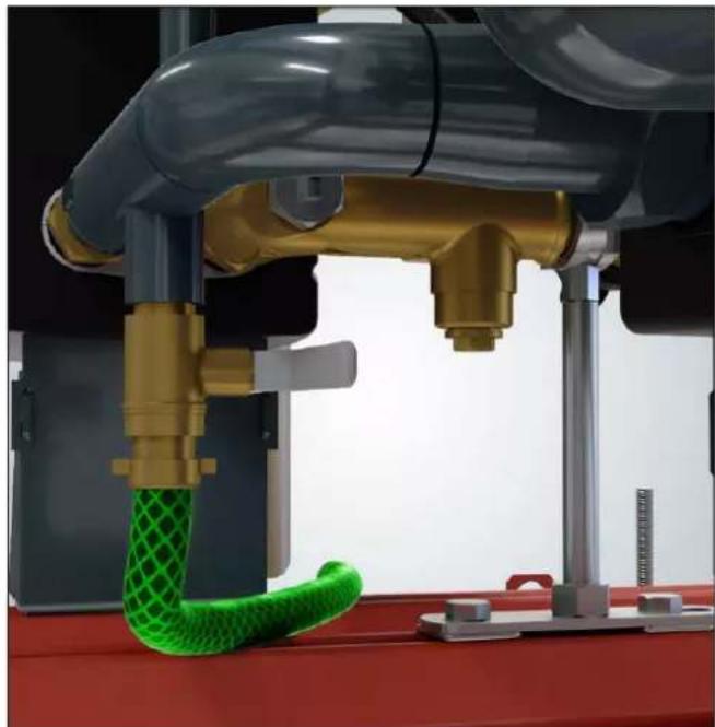
Locate the drain valves on the specific circuit which you would like to empty.

ATTENTION!
To drain the primary side, always close the shut-off valve on the district heating connection.

NOTE!
To drain only the substation and not the whole installation, close the shut-off valves on the substation.
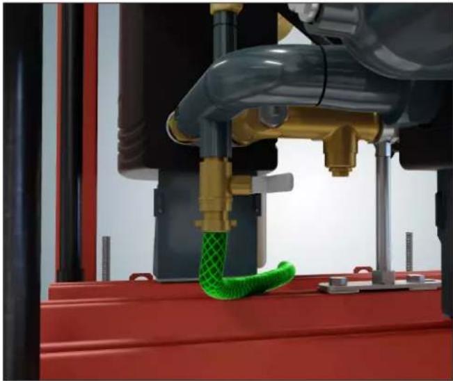
If the drain pipe is not connected to the drain valve, connect the appropriate hose or piping in accordance with local legal regulations.

WARNING! Risk of injury or damage!
Never operate the drain valve when the outlet is directed towards you or electrical devices. Always secure all equipment so that it is not flooded by accident. Before any operation always ensure that the water has cooled sufficiently.
natural_image
3D printer in operation with green mesh mesh being processed, no visible text or symbolsOpen the drain valve and wait until the circuit concerned has emptied. Immediately after draining, close the valve.

WARNING! Risk of injury!
Even after draining, there may still be water inside the heat exchanger and piping.
7.0 Commissioning
Commissioning must always be carried out before the following actions:
- Initial start-up of the substation
- Restarting after complex substation maintenance
- Restarting after the implementation of a new device
- Restart following a malfunction of the substation
- Restarting after shutdown or longer downtime
Installation and initial commissioning of the substation is carried out by approved employees of the manufacturer or authorised partner companies. Typically the local utility company must be involved in work relating to heating connections. Typically the district heating utility must be involved in work relating to primary connections. Unauthorised initial start-up is not allowed.
In order to commission the station the following conditions must be met:
• Station is reassembled on site (if is the case)
- Commissioning must be approved by the district heating utilities
- All screws and fasteners must be tightened
- Substation piping must be connected properly. It is prohibited in connection to Domestic hot water system to use black steal – risk corrosion heat exchanger
- Expansion tank is connected to the substation
- All impurities and leftover installation materials must be removed from the piping
- The station must be properly connected to electricity: the supply voltage must be applied to the main switch or circuit breaker according to the electrical diagram
- Other electrical / mechanical on site works are done according to electrical diagram
- The primary connection must be applied to the primary shut-off valves within the necessary parameters
- The secondary installation should be filled (including the substation) and vented (venting the pumps is necessary)
- Pressurisation must be ready with the required static pressure
- Venting / Drain valves are closed
- Desired time programmes and additional data for controller setup must be available
- The substation may only be put into operation when an authorised specialist from the district heating company or an expert from an installation company or an authorised specialist from the commercial office has approved the correct condition of the whole system.
• Make sure that the system is filled with water
- Make sure that a correct setup of temperature is made for Domestic hot water. To ensure maximum heat exchanger performance and life time Danfoss recommends maximum 60 deg. C.
Before commissioning, check that all safety-related rules and regulations have been taken into account.
- Working parameters for the substation's plate type must match the operating parameters of the local / district heating company and the heating system.
- Begin with secondary side
- Open (slowly) the isolating valves on secondary circuits
- Fill the secondary installation with water according to the water quality rules. To avoid substation damage, ensure that pressure during filling does not exceed the maximum allowable working pressure.
- Vent all the secondary installation (heating and DHW)
- Before first use, the secondary side must be rinsed sufficiently by the installation company. Fill the secondary installation to the required static pressure.
- Check all connections for leaks and tightness, and retighten with the required torque if necessary.
- Vent the pumps
- Move to primary side. All work on the primary side of the system must be carried out in coordination with the local / district heating company by suitably qualified and trained personnel.
- If the medium is water, set the flow / differential pressure controller or pressure controller (if available) to the maximum flow rate according to capacity or preset differential pressure. Than set up the pressure controller, if there is one, to the designated value.
- Fill the substation by slowly opening the shut-off valve on the primary supply. Also slowly open the shut-off valve on the primary return. Manually adjust the electronic controller to the "valve open" position.
- Vent (if is possible) the primary circuit
- Check all connections for leaks and tightness, and retighten with the required torque if necessary.
- Rinse the primary site with the district heating medium and reclose the shut-off valves. Clean the strainers.
- Switch on the main switch of the control panel (check automatic fuses in control panel and pumps switches)
- If available start each pump manually and check the direction of rotation
- Adjust the electronic con troller in accordance with the designated values in the enclosed supplier instructions.
- Check the actuators
- Switch all pumps in auto mode
- The electronic controller is preset in the factory in accordance with the data available to us. After commissioning, the controller auto matically performs a self-test, displays a default system code and automatically goes into operating mode. Now a precise setting must be made in accordance with the controller manufacturer's manual. The manual is attached to the station.
- Danfoss recommends the activation of all the needed optimization and protective functions like motor pr. (motor protection)
- Refer to technical documentation for detailed instruction for all components (e.g. pumps, controllers, actuators).
7.4 Requirements after commissioning
The following points must be checked after comisioning:
- Check temperatures
- Check pressures
- Check flows
- Thermal expansion
- Leakages
• Operation of pumps
• Control valves / actuators operation - Flow directions
• Operation of controllers - Noises
7.5 Fault and Shutdown
The heating controller, control valve actuator and heating pump are connected to electric power supply.
Therefore:
- Immediately turn off the main switch or unplug the power cable
- Close the second shut-off valves on the primary and secondary side
- A specialist company must be consulted for troubleshooting

WARNING! Electric shock hazard!
Leaking water can subject the entire substation to dangerous voltage. Before starting any work, switch the power OFF and ensure that it cannot be turned back on.

WARNING! Risk of burns!
In case of leakage on the primary side, the medium may escape as steam at a temperature of more than 100^ C. Danger of burns.
7.6 Commissioning after a failure or malfunction
After a failure on the primary side, always contact the local or district heating company. Recommissioning is to be carried out by a specialist company.
After a failure on the secondary side contact a specialist company. Recommissioning is to be carried out by the specialist company.
8.0 Operation
The substation works in fully automatic mode. During operation, no personnel are required either in the area of the substation or within its immediate vicinity.
8.1 Switching on
To turn the substation on, follow the requirements in the "Commissioning" chapter 7. The substation can be turned on at the main switch of the electronic controller and will start to operate automatically.
8.2 Switching off
The substation can be turned off at the main switch of the electronic controller and will stop automatically.
8.3 Restarting after substation shutdown
If the substation is to be turned off for a long period of time (i.e. without power) in order to save energy, then proceed with restart as for the first commissioning. Flushing of the system is recommended.
8.4 Service / clean - strainer
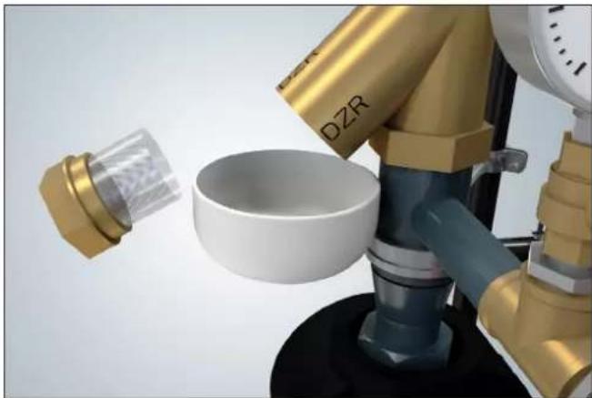
Before you begin cleaning, perform the actions described at point 2 (draining the system) and check that no components will collide when removing the mesh.
natural_image
Close-up of a 3D printer in operation with a green mesh object suspended between red metal frames (no text or symbols visible)Use a suitable flat spanner to unscrew (counterclockwise) the cap from the strainer, remove the mesh and clean it. Before closing the strainer check the seal (for tightness and integrity). If necessary, replace it. Do not let the water splash on electrical components.

WARNING! Risk of injury!
Even after draining, there may still be water inside the strainer.
natural_image
3D rendering of a robotic arm pouring liquid into a white bowl, with no visible text or symbols8.5 Service / disassembly and replacement – heat exchanger only brazed type
Before you begin any activities with the heat exchanger perform the actions described at point 2 (draining the system).
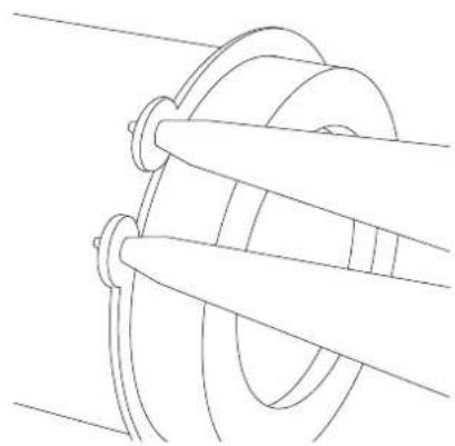
Use a suitable flat spanner to unscrew the piping from the heat exchanger and Seeger Pliers to remove the heat exchanger from the support frame.

WARNING! Risk of injury!
Even after draining, there may still be water inside the heat exchanger and piping.
natural_image
Pure mechanical diagram showing a pulley and rope structure without any text, numbers, or symbols8.6 Service / Check – Safety valve and expansion vessel
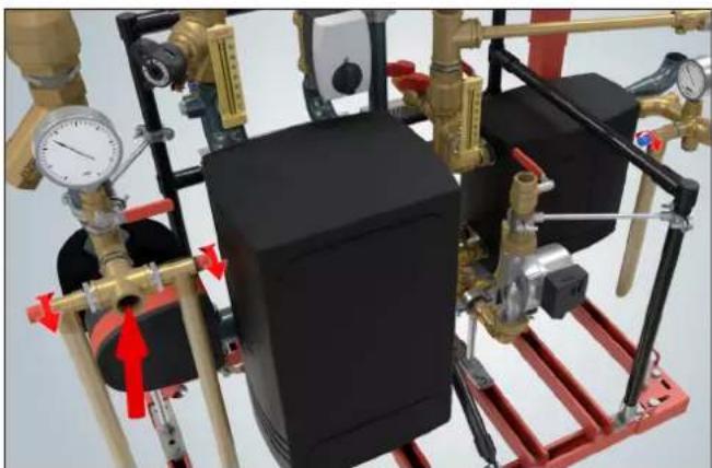
Locate the safety valves on the secondary side (these are separate on the heating and domestic hot water circuit). If the drain pipe is not connected to the safety valve, connect the appropriate hose or piping in accordance with local legal regulations.

WARNING! Risk of injury or damage!
Never operate a safety valve when the outlet is directed towards you or towards electrical devices. Always secure all equipment so that it will not be flooded by accident.
natural_image
Industrial piping and valve assembly with black box, yellow valves, and red frame (no visible text or symbols)Turn the lifting handle in the direction of the arrow until you hear a click. Then the valve must be closed tight.

NOTE!
If a valve drips constantly, it is very likely that impurities have built up in the seat. To clean the valve seat and seal, unscrew the head part.
Locate the connection for the expansion vessel.
Follow the expansion vessel servicing procedure for the relevant vessel type.
9.0 Maintenance
9.1 Safety warning
In the appendix you will find a summary of the most important technical requirements. It is recommended to hire an authorised installer for frequent maintenance.
It is necessary to check and maintain the substation on regular basis in order to keep it in good operating condition. The frequency of maintenance and service inspections should be done according to system manufacturer's recommendations and local legislation.
The most important actions for main components and assemblies are summarised under section 9.2. Other instructions for components not specified in this installation manual can be found separately in the accessory box and must be observed.

WARNING! Risk of injury!
In principle work may be carried out only by qualified and specially trained personnel. Avoid loosen tight clothing (no loose sleeves, rings, etc.). Always wear the following personal protective equipment in the vicinity of the substation:
- Safety glasses to protect the eyes from flying parts and fluids - Safety footwear for protection against heavy falling objects and slipping on slippery surfaces

WARNING! Electrical shock hazard!
Work on electrical equipment may only be carried out by a qualified electrician in accordance with the safety regulations.
Switch OFF the electrical supply before starting work and secure against reconnection.
9.2 Maintenance Plan (recommendations for maximum performance and life time)
Failure to follow a maintenance plan can result in mechanical or equipment failure that poses a danger to persons and goods and the entire workplace. Failure to document a maintenance plan will invalidate any warranty.
| Interval Maintenance Comments | ||
| Every 2 months | Check all connections If necessary re-tighten and / or replace seals | |
| Check all parameters to nominal / actual values or admissibility | If excessive, restore proper parameters | |
| General visual inspection of all components | In case of visible damage, perform a functional test and if necessary replace the component | |
| Every 6 months | Perform a functional test of the safety valve | Open the safety valve for a short period of time. Refer to point 8.6 |
| Perform a functional test of the electrical and electronic components, switches and so on | Manually switch the pump or open and close the actuator | |
| Perform an electrical test of the safety devices Temperature monitor, sensors and / or limiters | ||
| Clean strainers If necessary, refer to point 8.4 | ||
| Every 12 months | Perform a functional and usability check of all components | For example, open and close the shut-off valves |
| Perform a visual inspection of substation's appearance | Colour (rust), insulation | |
| Control of the heat exchanger | In case of contamination, clean / descale (refer to point 9.3) as needed | |
| Perform a visual inspection of the heat meter and water meter | Check legalisation period | |
| Perform a visual inspection of the measuring devices | Manometer, thermometer | |
| Perform a visual inspection of the expansion vessels | Shape of vessels, tamper head, tightness of the membrane | |
| The correct function of the pressure relief valve should be checked by qualified personnel at initial operation and then once a year | Turn the lifting handle in the direction of the arrow until you hear a click | |
9.3 Heat exchanger maintenance
The following is a list of important activities that should be performed during maintenance. Additional information is included in the attached manufacturer's instructions.
This abstract only provides information about the required steps. It is important in any case to comply with all relevant legal and technical regulations and requirements pertaining to local conditions and regulations (e.g. the home owner, district heating utilities, etc.)
Fittings:
In general, the fittings used are maintenance free. During maintenance, the functionality of hand wheels or levers should be tested in terms of ease of use by opening and closing. This will protect the ball, plates and valve seats against dirt and limescale deposits. See the manufacturer's instructions for the most common components in Annex I.
Heat exchanger:
Heat exchangers are designed for long-term use. Due to relatively high temperatures, in particular cases lime and other deposits may appear on the inner surface.
In case of reduced performance, the heat exchanger should be cleaned. For detailed information, please refer to the heat exchanger instructions.
Water quality:
To ensure maximum heat exchanger performance and lifetime, follow the Danfoss "Guideline to Water Quality for Copper Brazed Plate Heat Exchanger" – VJ.KV.D3.02 or a newer version.
9.4 Maintenance validation
Following maintenance work but before turning on the substation, please note the following:
- Check the tightness of all previously loosened threaded connections
- Verify that all previously removed components have been reinstalled correctly
- Ensure that all tools, materials and other equipment used during maintenance have been removed from the work area
- Clean up the work area, remove any spilled substances and remove any waste from material processing
- Make sure that the system and all unit safety devices are working properly again
10.0 Troubleshooting
Electrical equipment which has failed and mechanical, pneumatic and hydraulic components must be serviced only by qualified personnel with the relevant specialties.
Information about all failures which cannot be eliminated through the following actions is to be forwarded to the substation manufacturer or to service partners authorised by Danfoss.
| Malfunction Possible Solution | on Comment | ||
| Secondary water temperature is too low | Lack of supply voltage | Check if main switch is turn on Check cabling Check fuses | Contact authorised personnel or electric energy supplier |
| Lack of heat supply- No primary system pressure- Primary differential pressure is too low- Heating water flow is too flow | Check and secure operating conditions:- Pressure- Flow- Differential pressure | Contact district heating utility Adjust flow limiter settings | |
| Incorrect controller setting(s) Check and correct settings Read controller's user's manual | |||
| Defective controller Replace controller Contact customer service | |||
| Closed shut-off valve(s) Open shut-off valves | |||
| Defective sensor Replace the sensor | Check values and if necessary replace sensor | ||
| Circulation pump(s) defective or not switched ON | Switch ON / replace circulation pump(s) | ||
| Heating pump(s) defective or not switched ON | Switch ON / replace heating pump(s) | ||
| Balancing valve not set correctly | Adjust balancing valve to correct value | Set designated flow | |
| Circulation pump is not running at the intended speed | Increase or decrease pump speed / replace pump | Set designated flow | |
| Defective control valve Clean or replace valve | |||
| Defective actuator or thermostat | Replace defective actuator or thermostat | ||
| Substation is sized incorrectly - usually primary control valve is too big or too small | Check dimensioning Extend / enlarge substation (calculate dimensions for new control valve and replace old one) | Contact our sales staff responsible | |
| Reduced flow through heat exchanger | Clean / replace heat exchanger | Read heat exchanger user's manual | |
| Outdoor sensor is placed incorrectly | Place outdoor sensor correctly | Read electronic controller user's manual. | |
| Secondary water temperature is too high | Missing supply voltage -> actuator is in open position | Take the system out of operation and close valve manually. After providing power supply, go back into standard mode | |
| Incorrect controller setting(s) Check and correct setting(s) Read controller's user manual | |||
| Defective sensor Replace the sensor | Check values and if necessary replace sensor | ||
| Defective control valve Clean or replace valve | |||
| Defective actuator or thermostat Replace actuator / thermostat | Actuator still open or thermostat / defective capillary | ||
| Circulation pump is not running at the intended speed | Increase or decrease pump speed / replace pump | Set designated flow | |
| Malfunction Possible Solution | Comment | ||
| Secondary water temperature oscillating or not constant | Incorrect controller setting(s) | Correct settings e.g.:- Xp (proportional band)- Tn (integration time constant)- M run (running time of the motorised control valve) | Read controller's user manual |
| Fluctuating heating water supply- Fluctuating primary differential pressure- Fluctuating primary flow | Check and secure operating conditions:- Pressure- Flow- Differential pressure | ||
| Primary control valve is too large | Control valve needs to be recalculated, replace if necessary | Contact our sales staff responsible | |
| Leakage*Risk of scalding! | Connection leakages (flange / fittings, couplings) | Turn off substation:- Check operating parameters and test for admissibility (see label)- Check connections and tighten as necessary or replace seals | |
| Leakage of welds Turn off substation | Contact customer service | ||
| Leaks from fittings (housing / couplings) | Tighten connection or replace component | Contact customer service | |
| - Leakage of gasket heat ex-changers- Pollution / calcification- Pressure hammers | - Tighten bolts- Open and clean plates- Change seals if necessary | Read heat exchangeruser's manual or contact customer service | |
| - Leakage of brazed or welded heat exchangers- Pollution / calcification- Pressure hammers | Replace heat exchanger Contact customer service | ||
| Unacceptable pressure increase, constant blow up of safety valve | Internal leakage of the heat exchanger | Test heat exchanger and replace if necessary | Contact customer service |
| Incorrect adjustment and filling pressure | Check vessel and pressurisation (static pressure) | Check and adjust parameters | |
| Defective pressure equipment or expansion vessel | Replace component(s) | ||
| Incorrect opening pressure / dimension or defective safety valve | Replace safety valve | ||
| Incorrect setting of pressure re-ducer / pressure relief controller | Check / correct device setting Read device user's manual | ||
| Pressure surges, water hammer | Secondary side - fluctuating supply temperatures | Check control valve settings (characteristics in particular) | |
| Secondary side - abruptly changing operating conditions:- Disconnection of system parts- Closing of valves- Pumps switching OFF | Check control valve settings (characteristics in particular)Check system settings / interplay of the entire system | ||
| Incorrect adjustment and filling pressure | Check vessel and pressurisation (static pressure) | Check and adjust parameters | |
| Defective pressure equipment or expansion vessel | Replace component(s) | ||
| Incorrect opening pressure / dimension or defective safety valve | Replace safety valve | ||
*May not be applicable for some products or product variants.
| Malfunction Possible Solution | Comment | ||
| Excessive noise | Incorrect pump setting Check / correct setting Read pump manual | ||
| Missing hydraulic set-up | Check and correct settings of balancing components | Read device user's manual | |
| Flow noise (e.g. in pipes) | Check flow and hydraulic setupCheck if extraneous objects are inside piping | Rinse the substation | |
| Loose parts inside components | Check functionality of non-return valves (spring) | ||
| System incorrectly dimensioned, e.g. primary control valve is too small | Check dimensioning Extend / enlarge substation (calculate dimensions for new control valve and replace old one) | Contact our sales staff responsible | |
| Defective control valve Clean valve | |||
| Defective pump impeller Replace pump | |||
| No heat | Strainer clogged on DH or HE side Clean strainer | ||
| Filter in district heating meter clogged | Clean the filter (after consulting district heating plant) | ||
| Defective differential pressure controller | Check functionality of differential pressure controller | Clean valve seat if required | |
| Defective sensor Replace the sensor | Check values and if necessary replace sensor | ||
| Defective actuator or thermostat | Replace defective actuator or thermostat | ||
| Defective control valve or possibly dirt in the valve housing | Check the functions of the control valve - clean valve housing if required | ||
| Automatic controls incorrectly set or defective - possible power failure. | Check that the controller setting is correct - see separate instructions. Check the power supply. Temporary set the actuator to "manual" control - see the instructions for heating circuit, manual control | ||
| Pump out of operation | Check that the pump is receiving power and that it runs. Make sure that there is no air in the pump housing - see pump manual | ||
| The pump rotation speed is set too low | Set the pump at a higher speed of rotation - see instructions for heating circuit | ||
| Air in the system Vent the installation thoroughly |
10.1 Safety

WARNING! Risk of injury!
Improper troubleshooting can lead to serious personal injury and / or property damage. Therefore troubleshooting of malfunctions may be performed only by trained and authorised personnel!
10.2 Steps to take in the event of malfunction
In summary:
- Immediately stop the substation using the emergency stop function when there are faults that can cause immediate danger to persons, property and / or operational security.
- Switch OFF the substation when there are faults that do not pose such dangers. Additionally, interrupt the power supply to the unit and secure against reconnection.
- Immediately inform superior about fault.
- Request authorised personnel to determine the nature and extent of the disorder and the cause of the malfunction, and to repair the malfunction.
11.0 Spare parts
Use only original spare parts from the manufacturer.

WARNING!
Incorrect or faulty spare parts and / or components from other manufacturers may cause serious damage to and/or malfunction or failure of the substation.
Using non-approved spare parts will invalidate all warranty, service, damage and/or liability claims against the manufacturer or its agents, distributors and representatives.
When ordering spare parts, always specify:
- Substation type
- Serial / production number
• Part number / article number (if available)
• Quantity - Name
- Shipping address
- If needed, provide a sketch or photo with remarks
• Desired shipping method (post, freight, sea, air, express)
Spare part orders without the above specifications may not be fulfilled. In the absence of a desired shipping method, the shipping method will be at the discretion of the supplier.
In the annex, you can find a list of the most important suppliers of purchased components, where spare parts may be requested following the expiry of the warranty. In such a case, provide the manufacturer with comprehensive information about the used parts so that a replacement can be offered.
A
actuator 11, 20, 24, 26, 28
assembly 2, 8, 14, 15, 17
authorized personnel 5, 26, 29
B
balancing valve 26
C
circuit 2,9,10,11,12,18,19,23,28
circulation 12, 26
commissioning 2, 8, 15, 19, 20
component 15, 24, 27
connections 8, 11, 13, 14, 15, 19, 24, 25, 27
control valves 11
controller 11, 19, 20, 26, 27, 28
D
District Heating 5, 11, 15, 18, 19, 20, 25, 26, 28
domestic hot water 2,12
drain 4, 6, 8, 11, 12, 18, 23
drinking water 4,11
DSE FLEX 1, 2, 9, 11, 12, 15
E
electrician 3, 15, 24
employees 19
EPP 22
expansion vessel 2, 23, 24, 27
F
fittings 8, 12, 25, 27
flat spanner 21, 22
flow noise 28
H
hazard 3, 6, 20, 24
heat exchanger 2, 9, 11, 12, 22, 24, 25, 26, 27
heating supply 15
hot surfaces 6
|
installation 3,4,5,9,11,12,14,15,18,19,24,28
installer 24
Intended use 5
L
loose components 15
M
maintenance 2, 3, 5, 6, 7, 11, 12, 19, 24, 25
Maintenance Plan 30
malfunction 3,4,19,29
O
operator 2, 5, 7, 19
P
packing 16
personnel 5,7,8,14,15,19,20,24,26,29
primary connection 15, 19
protective clothing 8
protective gloves 6
pump 11, 12, 20, 24, 26, 28
R
reconnection 6, 24, 29
risk 2, 3, 5, 6, 8, 13, 16
S
safety rules 13
safety valve 12, 23, 24, 27
scrap 4
secondary side 11, 19, 20, 23
Seeger Circlip Ring Pliers 22
sensor 12, 15, 26, 28
service 4,6,26,27,29
spare parts 4, 29
strainer 2, 11, 12, 15, 19, 21, 24, 28
substation 2,3,4,5,6,7,8,9,11,12,13,14,15,16,17,18,19,20,
22, 24, 25, 26, 27, 28, 29
T
technical requirements 12
thermometer 11,24
transport 6, 9, 13, 14, 16
troubleshooting 20, 29
U
unpacking 2,16
V
voltage 9, 19, 20, 26
W
warranty 3,5,15,19,29
District Heating Substations
Danfoss A/S
Heating Segment · heating.danfoss.com · +45 7488 2222 · E-Mail: heating@danfoss.com
Danfoss can accept no responsibility for possible errors in catalogues, brochures and other printed material. Danfoss reserves the right to alter its products without notice. This also applies to products already on order provided that such alterations can be made without subsequential changes being necessary in specifications already agreed. All trademarks in this material are property of the respective companies. Danfoss and all Danfoss logotypes are trademarks of Danfoss A/S. All rights reserved.
- District Heating Substations
- Caution!
- Table of contents
- General information
- Information on installation and operating instruction manual
- Other applicable documents
- Explanation of symbols
- WARNING!
- Liability and warranty
- NOTE!
- NOTE
- Copyright
- Spare parts
- Dismantling
- Disposal
- Safety
- General information
- Responsibility of the operator
- Intended use
- Possible misuse
- WARNING. Hazard from improper use!
- Safety work
- Therefore:
- Personal protective equipment
- Protective clothing
- Protective gloves
- Possible hazards of the device
- WARNING! Risk of injury!
- WARNING! Electrical hazard!
- Safety goggles
- Safety footware
- Protective helmet
- WARNING! Risk of burning!
- WARNING! Risk of crushing!
- Emergency stop switch
- Operating personnel
- Actions in the event of danger or accidents
- Technical data
- Technical and main system data
- CE label
- Dimensions and packaging
- Function and configuration
- Function
- Danfoss Substation configuration possibilities
- Transport, packaging and storage
- Transport of pallets by forklift
- Procedure:
- Follow safety rules:
- Transport inspection
- WARNING! Danger to life!
- Packaging
- Storage
- Installation
- Installation preparation
- Primary connection
- Secondary connection
- Electrical connection
- ATTENTION
- Draining station
- ATTENTION!
- WARNING! Risk of injury or damage!
- Commissioning
- Requirements after commissioning
- Fault and Shutdown
- WARNING! Electric shock hazard!
- WARNING! Risk of burns!
- Commissioning after a failure or malfunction
- Operation
- Switching on
- Switching off
- Restarting after substation shutdown
- Service / clean - strainer
- Service / disassembly and replacement – heat exchanger only brazed type
- Service / Check – Safety valve and expansion vessel
- Maintenance
- Safety warning
- WARNING! Electrical shock hazard!
- Maintenance Plan (recommendations for maximum performance and life time)
- Heat exchanger maintenance
- Fittings:
- Heat exchanger:
- Water quality:
- Maintenance validation
- Troubleshooting
- Safety
- Steps to take in the event of malfunction
- Spare parts
- A
- B
- C
- D
- E
- F
- H
- |
- L
- M
- O
- P
- R
- S
- T
- U
- V
- W
- Danfoss A/S
Brand : DANFOSS
Model : District Heating Substations
Category : District Heating Substations