23-400H - Planer RIKON - Free user manual and instructions
Find the device manual for free 23-400H RIKON in PDF.


| Product Type | Benchtop Thickness Planer |
| Brand | RIKON |
| Model | 23-400H |
| Maximum Planing Width | 13 inches |
| Maximum Planing Depth | 6 inches |
| Maximum Depth of Cut | 1/8 inch per pass |
| Cutterhead Speed | 10,000 RPM |
| Number of Knives | 3 (HSS or Carbide, optional) |
| Feed Rate | 26 feet per minute |
| Motor Power | 2 HP (peak), 15 Amp, 120V AC |
| Table Size | 13 x 28 inches |
| Dust Port Diameter | 2.5 inches (with adapter for 4") |
| Weight | 62 lbs (28 kg) |
| Overall Dimensions (L x W x H) | 30 x 20 x 18 inches |
| Safety Features | Blade guard, lock-out switch, anti-kickback pawls |
| Maintenance | Periodic dust removal, blade sharpening/replacement, roller cleaning |
| Spare Parts Available | Knives, belts, rollers, drive chain |
| Warranty | 5-year limited warranty |
Frequently Asked Questions - 23-400H RIKON
User questions about 23-400H RIKON
0 question about this device. Answer the ones you know or ask your own.
Ask a new question about this device
Download the instructions for your Planer in PDF format for free! Find your manual 23-400H - RIKON and take your electronic device back in hand. On this page are published all the documents necessary for the use of your device. 23-400H by RIKON.
USER MANUAL 23-400H RIKON
16" Thickness Planer with Helical Cutterhead

natural_image
Exterior view of a RIKON industrial machine with visible control panel and roller mechanism (no text or symbols on the machine itself)
Intertek 4001824
Operator's Manual
Record the serial number and date of purchase in your manual for future reference.
Serial Number: ____ Date of purchase: ____
For technical support or parts questions, email techsupport@rikontools.com or call toll free at (877)884-5167
TABLE OF CONTENTS
Specifications....2
Safety Instructions 3 - 6
Getting To Know Your Machine ....7
Contents of Package 7 - 8
Assembly 8 - 9
Operation 10 - 11
Adjustments 12 - 16
Maintenance 17
Wiring Diagram 17
Troubleshooting 18
Parts Diagrams & Parts Lists 19 - 25
Warranty 26
Accessories 27
Notes 27
SPECIFICATIONS
Motor 3 HP, TEFC
Motor Speed (no load).... 3,400 RPM
Volts 220 V
Amps, Hertz 12 A, 60 Hz
Cutterhead Diameter 2-3/4" (70 mm)
Cutterhead Speed (RPM / CPM)....5,100 RPM / 20,400 CPM
Number of Carbide Inserts, 4-sided....72
Maximum Depth of Cut 1/8" (3 mm)
Maximum Cutting Width 16" (406 mm)
Maximum Cutting Depth (Height) 8-13/16" (225 mm)
Feed Speed SF/min 16 to 23 (5 to 7 SM/min)
Dust Port 4-3/4" Diameter (120 mm)
Dust Collection Minimum CFM 650
Noise Level (no load) ....≤85dB
Overall Size (LxWxH)....55" x 24-1/4" x 42-1/2" (1400 x 616 x 1080 mm)
Base Size 24-5/8" x 22-1/4" (627 x 565 mm)
Net Weight 375 lbs (170 kg)
This owner's manual is not a teaching aid and is intended to show assembly, adjustments, and general use.
NOTE: The specifications, photographs, drawings and information in this manual represent the current model when the manual was prepared. Changes and improvements may be made at any time, with no obligation on the part of Rikon Power Tools, Inc. to modify previously delivered units. Reasonable care has been taken to ensure that the information in this manual is correct, to provide you with the guidelines for the proper safety, assembly and operation of this machine.
SAFETY INSTRUCTIONS
IMPORTANT! Safety is the single most important consideration in the operation of this equipment. The following instructions must be followed at all times. Failure to follow all instructions listed below may result in electric shock, fire, and/or serious personal injury.
There are certain applications for which this tool was designed. We strongly recommend that this tool not be modified and/or used for any other application other than that for which it was designed. If you have any questions about its application, do not use the tool until you have contacted us and we have advised you.
SAFETY SYMBOLS

SAFETY ALERT SYMBOL: Indicates DANGER, WARNING, or CAUTION. This symbol may be used in conjunction with other symbols or pictographs.

DANGER
serious injury.
Indicates an imminently hazardous situation, which, if not avoided, could result in death or

WARNING
injury.
Indicates a potentially hazardous situation, which, if not avoided, could result in death or serious

CAUTION
moderate injury.
Indicates a potentially hazardous situation, which, if not avoided, could result in minor or
NOTICE: Shown without Safety Alert Symbol indicates a situation that may result in property damage.
GENERAL SAFETY
KNOW YOUR POWER TOOL. Read the owner's manual carefully. Learn the tool's applications, work capabilities, and its specific potential hazards.
BEFORE USING YOUR MACHINE
To avoid serious injury and damage to the tool, read and follow all of the Safety and Operating Instructions before operating the machine.
- Some dust created by using power tools contains chemicals known to the State of California to cause cancer, birth defects, or other reproductive harm.
Some examples of these chemicals are:
- Lead from lead-based paints.
• Crystalline silica from bricks, cement, and other - masonry products.
- Arsenic and chromium from chemically treated lumber.
Your risk from these exposures varies, depending on how often you do this type of work. To reduce your exposure to these chemicals: work in a well ventilated area and work with approved safety equipment, such as those dust masks that are specially designed to filter out microscopic particles.
- READ the entire Owner's Manual. LEARN how to use the tool for its intended applications.
-
GROUND ALL TOOLS. If the tool is supplied with a 3-prong plug, it must be plugged into a 3-contact electrical receptacle. The 3rd prong is used to ground the tool and provide protection against accidental electric shock. DO NOT remove the 3rd prong. See Grounding Instructions on the following pages.
-
AVOID A DANGEROUS WORKING ENVIRONMENT. DO NOT use electrical tools in a damp environment or expose them to rain.
- DO NOT use electrical tools in the presence of flammable liquids or gasses.
- ALWAYS keep the work area clean, well lit, and organized. DO NOT work in an environment with floor surfaces that are slippery from debris, grease, and wax.
- KEEP VISITORS AND CHILDREN AWAY. DO NOT permit people to be in the immediate work area, especially when the electrical tool is operating.
- DO NOT FORCE THE TOOL to perform an operation for which it was not designed. It will do a safer and higher quality job by only performing operations for which the tool was intended.
- WEAR PROPER CLOTHING. DO NOT wear loose clothing, gloves, neckties, or jewelry. These items can get caught in the machine during operations and pull the operator into the moving parts. The user must wear a protective cover on their hair, if the hair is long, to prevent it from contacting any moving parts.
- CHILDPROOF THE WORKSHOP AREA by removing switch keys, unplugging tools from the electrical receptacles, and using padlocks.
-
ALWAYS UNPLUG THE TOOL FROM THE ELECTRICAL RECEPTACLE when making adjustments, changing parts or performing any maintenance.
-
KEEP PROTECTIVE GUARDS IN PLACE AND IN WORKING ORDER.
-
AVOID ACCIDENTAL STARTING. Make sure that the power switch is in the "OFF" position before plugging in the power cord to the electrical receptacle.
-
REMOVE ALL MAINTENANCE TOOLS from the immediate area prior to turning "ON" the machine.
-
USE ONLY RECOMMENDED ACCESSORIES. Use of incorrect or improper accessories could cause serious injury to the operator and cause damage to the tool. If in doubt, check the instruction manual that comes with that particular accessory.
-
NEVER LEAVE A RUNNING TOOL UNATTENDED. Turn the power switch to the "OFF" position. DO NOT leave the tool until it has come to a complete stop.
-
DO NOT STAND ON A TOOL. Serious injury could result if the tool tips over, or you accidentally contact the tool.
-
DO NOT store anything above or near the tool where anyone might try to stand on the tool to reach it.
-
MAINTAIN YOUR BALANCE. DO NOT extend yourself over the tool. Wear oil resistant rubber soled shoes. Keep floor clear of debris, grease, and wax.
-
MAINTAIN TOOLS WITH CARE. Always keep tools clean and in good working order. Keep all blades and tool bits sharp, dress grinding wheels and change other abrasive accessories when worn.
-
EACH AND EVERY TIME, CHECK FOR DAMAGED PARTS PRIOR TO USING THE TOOL. Carefully check all guards to see that they operate properly, are not damaged, and perform their intended functions. Check for alignment, binding or breaking of moving parts. A guard or other part that is damaged should be immediately repaired or replaced.
-
DO NOT OPERATE TOOL WHILE TIRED, OR UNDER THE INFLUENCE OF DRUGS, MEDICATION OR ALCOHOL.
-
SECURE ALL WORK. Use clamps or jigs to secure the workpiece. This is safer than attempting to hold the workpiece with your hands.
-
STAY ALERT, WATCH WHAT YOU ARE DOING, AND USE COMMON SENSE WHEN OPERATING A POWER TOOL.
A moment of inattention while operating power tools may result in serious personal injury.
-
ALWAYS WEAR A DUST MASK TO PREVENT INHALING DANGEROUS DUST OR AIRBORNE PARTICLES, including wood dust, crystalline silica dust and asbestos dust. Direct particles away from face and body. Always operate tool in well ventilated area and provide for proper dust removal. Use dust collection system wherever possible. Exposure to the dust may cause serious and permanent respiratory or other injury, including silicosis (a serious lung disease), cancer, and death. Avoid breathing the dust, and avoid prolonged contact with dust. Allowing dust to get into your mouth or eyes, or lay on your skin may promote absorption of harmful material. Always use properly fitting NIOSH/OSHA approved respiratory protection appropriate for the dust exposure, and wash exposed areas with soap and water.
-
USE A PROPER EXTENSION CORD IN GOOD CONDITION. When using an extension cord, be sure to use one heavy enough to carry the current your product will draw. The table on the following page shows the correct size to use depending on cord length and nameplate amperage rating. If in doubt, use the next heavier gauge. The smaller the gauge number, the larger diameter of the extension cord. If in doubt of the proper size of an extension cord, use a shorter and thicker cord. An undersized cord will cause a drop in line voltage resulting in a loss of power and overheating.
USE ONLY A 3-WIRE EXTENSION CORD THAT HAS A 3-PRONG GROUNDING PLUG AND A 3-POLE RECEPTACLE THAT ACCEPTS THE TOOL'S PLUG.
- ADDITIONAL INFORMATION regarding the safe and proper operation of this product is available from:
• Power Tool Institute 1300 Summer Avenue Cleveland, OH 44115-2851 www.powertoolinstitute.org
• National Safety Council 1121 Spring Lake Drive Itasca, IL 60143-3201 www.nsc.org
• American National Standards Institute 25 West 43rd Street, 4th Floor New York, NY 10036 www.ansi.org
• ANSI 01.1 Safety Requirements for Woodworking Machines and the U.S. Department of Labor regulations www.osha.gov
- SAVE THESE INSTRUCTIONS. Refer to them frequently and use them to instruct others.
ELECTRICAL SAFETY
EXTENSION CORDS
WARNING:
THIS TOOL REQUIRES THE INSTALLATION OF A 220V PLUG (NOT INCLUDED), AND MUST BE GROUNDED WHILE IN USE TO PROTECT THE OPERATOR FROM ELECTRIC SHOCK.
IN THE EVENT OF A MALFUNCTION OR BREAK-DOWN, grounding provides the path of least resistance for electric current and reduces the risk of electric shock. This tool is equipped with an electric cord that has an equipment grounding conductor and requires a grounding plug (not included). The plug MUST be plugged into a matching electrical receptacle that is properly installed and grounded in accordance with ALL local codes and ordinances.
DO NOT MODIFY ANY PLUG. If it will not fit the electrical receptacle, have the proper electrical receptacle installed by a qualified electrician.
IMPROPER ELECTRICAL CONNECTION of the equipment grounding conductor can result in risk of electric shock. The conductor with the green insulation (with or without yellow stripes) is the equipment grounding conductor. DO NOT connect the equipment grounding conductor to a live terminal if repair or replacement of the electric cord or plug is necessary.
CHECK with a qualified electrician or service personnel if you do not completely understand the grounding instructions, or if you are not sure the tool is properly grounded when installing or replacing a plug.
REPLACE A DAMAGED OR WORN CORD IMMEDIATELY.
This tool is intended for use on a circuit that has a 220 volt electrical receptacle. FIGURE A shows the type of the 220v, 3-wire electrical plug and electrical receptacle that has a grounding conductor that is required.
Sample of 220 volt plug required for this machine.

NEMA 6-20P
Consult a qualified electrician if the distance of the machine from the electrical panel is greater than 30 feet.
FIG. A
WARNING:
USE OF AN EXTENSION CORD WITH THIS MACHINE IS NOT RECOMMENDED. FOR BEST POWER AND SAFETY, PLUG THE PLANER DIRECTLY INTO A DEDICATED GROUNDED ELECTRICAL OUTLET THAT IS WITHIN THE SUPPLIED CORD LENGTH OF THE MACHINE.
IF AN EXTENSION CORD NEEDS TO BE USED, IT SHOULD ONLY BE FOR LIMITED OPERATION OF THE PLANER. THE EXTENSION CORD SHOULD BE AS SHORT AS POSSIBLE IN LENGTH, AND HAVE A MINIMUM GAUGE SIZE OF 14AWG.
USE ONLY A 3-WIRE EXTENSION CORD THAT HAS THE PROPER TYPE OF A 3-PRONG GROUNDING PLUG THAT MATCHES THE MACHINE'S 3-PRONG PLUG AND ALSO THE 3-POLE RECEPTACLE THAT ACCEPTS THE TOOL'S PLUG. *
WARNING:
Check extension cords before each use. If damaged replace immediately. Never use a tool with a damaged cord, since touching the damaged area could cause electrical shock, resulting in serious injury.
Use a proper extension cord. Only use cords listed by Underwriters Laboratories (UL). Other extension cords can cause a drop in line voltage, resulting in a loss of power and overheating of tool. When operating a power tool outdoors, use an outdoor extension cord marked "W-A" or "W". These cords are rated for outdoor use and reduce the risk of electric shock.
WARNING Keep the text
sion cord clear
of the working area. Position the cord so that it will not get caught on lumber, tools or other obstructions while you are working with a power tool.
* Canadian electrical codes require extension cords to be certified SJT type or better.
** The use of an adapter in Canada is not acceptable.

THIS SYMBOL DESIGNATES THAT THIS TOOL IS LISTED BY THE INTERTEK TESTING SERVICES, TO UNITED STATES AND CANADIAN STANDARDS.
Intertek
SPECIFIC SAFETY INSTRUCTIONS FOR PLANERS
This machine is intended for surface thickness planing of natural, solid woods. The permissible workpiece dimensions must be observed (see Technical Specification). Any other use not as specified, including modification of the machine or use of parts not tested and approved by the equipment manufacturer can cause unforeseen damage.
ATTENTION: Use of this planer still presents risks that cannot be eliminated by the manufacturer. Therefore, the user must be aware that wood working machines are dangerous if not used with care and all safety precautions are adhered to.
- Do not operate this machine until you have read all of the following instructions.
- Do not attempt to operate this machine until it is completely assembled.
- Do not turn ON this machine if any pieces are damaged or missing.
- This machine must be properly grounded.
- If you are not familiar with the operation of the machine, obtain assistance from a qualified person.
- Always wear approved, safety protective eye wear and hearing protection when operating this machine.
- Always wear a dust mask and use adequate dust collection and proper ventilation.
- Do not wear loose clothing or jewelry when operating this machine. Keep long hair tied back.
- Always make sure the power switch is in the OFF position prior to plugging in the machine.
- Always make sure the power switch is in the OFF position and the machine is unplugged when doing any cleaning, assembly, setup operation, or when not in use.
- Make sure all safety guards and hardware are securely tightened before operating the machine.
- Regularly check that the blades are locked tight in the cutterhead.
- Always keep hands and fingers away from the cutterhead, chip exhaust opening, feed rollers, belts and pulleys to prevent injury.
- Never make planing cuts deeper than 1/8". Multiple cuts, 1/16" or less, produce better finish results.
- Make sure there are no loose knots, nails, staples, dirt or foreign objects in the workpiece to be planed.
- Use extra caution with large, warped, very small or awkward workpieces. Joint warped boards flat before planing.
- Use extra supports (roller stands, saw horses, tables etc,) for any workpieces large enough to tip when not held down to the table top.
- Plane wood in the same direction of the grain, not across the grain. Never plane end cuts or end grain.
- Plane only one workpiece at a time. Vary the feeding of the workpieces along the cutterhead, center/left/right, so that all of the knives get used and thus remain sharp, longer.
- Never reach inside of a running machine, and avoid awkward operations and hand positions where a sudden slip could cause fingers or a hand to move into the cutterhead.
- Do not clear a jammed workpiece while the machine is running. Stop the planer, unplug it from the power source, and then remove the jammed workpiece. Lowering the table may be necessary to dislodge the workpiece.
- Keep your face and body to one side of the planer during use, out of line with a possible 'kick back' (lumber caught in by the rotating cutterhead and thrown back towards the operator).
- The use of any accessories or attachments not recommended may cause injury to you and damage your machine.
- Sharpen or replace dull or chipped knives immediately, as injury to the user, or the machine, may result.
- Replacement knives/inserts should be from, or through a source recommended by the manufacturer.
- Remove material or debris from the work area. Keep work area neat and clean.
SAVE THESE INSTRUCTIONS.
Refer to them often.
California Proposition 65 Warning
WARNING: Some dust created by power sanding, sawing, grinding, drilling, and other construction activities contains chemicals known to the State of California to cause cancer and birth defects or other reproductive harm. Your risk from exposure to these chemicals varies, depending on how often you do this type of work. To reduce your exposure, work in a well-ventilated area and with approved safety equipment, such as dust masks that are specially designed to filter out microscopic particles.
For more detailed information about California Proposition 65 log onto rikontools.com.
GETTING TO KNOW YOUR MACHINE

A. Planer Table
B. Cutterhead, Chip Breaker & Guard
C. Cover On/Off Micro Switch
D. Cover Opening Knob & Handle
E. Cover
F. Cover Lift Bar & Bracket
G. On/Off Switch
H. Height Setting Wheel for Planer Table
I. Locking Lever for Planer Table
J. Infeed Roller Table
K. Stock Return Rollers
L. Outfeed Roller Table
M. Dust Port
N. Adjustment Handle for Feed Speed
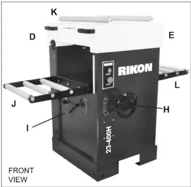

CONTENTS OF PACKAGE
Carefully unpack your planer from its carton. Check for any shipping damage, and make sure the following parts are included. If any parts are missing or broken, please call RIKON Customer Service (877-884-5167) as soon as possible for replacements. DO NOT turn your machine ON if any of these items are missing. You may cause injury to yourself or damage to the machine.
LIST OF LOOSE PARTS

natural_image
Two black mechanical components labeled A and B, shown from different angles (no text or symbols on the parts themselves)A. Hand Wheel
B. 4-3/4" to 4" Dust Hose Adapter
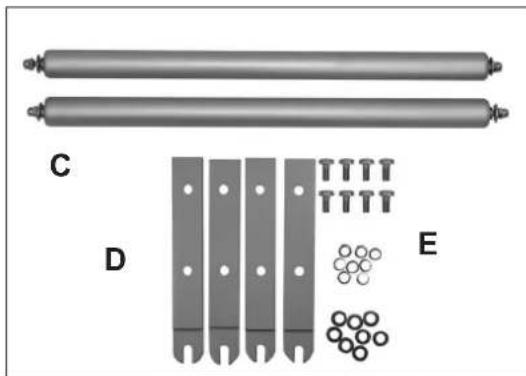
natural_image
Diagram of cylindrical components and a row of circular elements, labeled C, D, E (no text or symbols on main objects)C. Stock Return Rollers
D. Roller Supports
E. Roller Installation Hardware
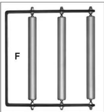
natural_image
Three vertical cylindrical objects connected by a black wire, labeled 'F' on the left (no other text or symbols)F. Extension Roller Tables (2)
CONTINUED on page 8
CONTENTS OF PACKAGE
Tools for Assembly & Adjustments
A. Wrenches - 13mm, 10mm & 8mm
B. Star T25 Screwdriver
C. Hex Wrenches - 2.5mm, 4mm & 5mm

natural_image
Assorted wrenches and screwdriver tools arranged on a plain surface (no text or symbols visible)ASSEMBLY

WARNING
THE PLANER MUST NOT BE PLUGGED IN AND THE POWER SWITCH MUST BE IN THE OFF POSITION UNTIL ASSEMBLY IS COMPLETE.
Unpacking and Clean-up
- Carefully remove all contents from the shipping carton. Compare the contents with the list of contents to make sure that all of the items are accounted for, before discarding any packing material. Place parts on a protected surface for easy identification and assembly.
- Report any shipping damage to your local distributor.
- Clean all rust protected surfaces with ordinary house hold type grease or spot remover. Do not use; gasoline, paint thinner, mineral spirits, etc. These may damage painted surfaces.
- Apply a coat of paste wax to the table to prevent rust. Wipe all parts thoroughly with a clean dry cloth. Be careful when reaching inside of the planer as the knives are sharp and may cause injury if touched.
- Set packing material and shipping carton aside. Do not discard until the machine is set up and is running properly.
INSTALLING THE PLANER

CAUTION
When moving the planer, DO NOT carry it with the infeed and outfeed rollers. Use a forklift, or pallet jack under the machine to lift and move the planer.
- Position the planer on a solid, level foundation that is located in an area that ample space in front and in back of the planer for the moving of lumber to be milled. Align the machine so that during use, any kickback will not face aisles, doorways, or other work areas that bystanders may be in. Do not locate or use the machine in damp or wet conditions.
- The planer is firmly bolted to a pallet with 4 bolts and nuts. Once the planer is in the area where it will reside, unbolt the planer from the pallet. The bolts are located through the two openings at the bottom sides of the planer. Carefully inch-it off the pallet by pushing the lower body/frame of the planer. DO NOT push the upper lid as this may damage the machine. FIG. 1.
- Secure the machine to the floor with lag screws (not supplied). Use the same 4 holes that secured the planer to the pallet for transport.
INSTALLING THE HAND WHEEL
The hand wheel, which raises and lowers the planer's table, must be installed. FIG. 2.
- Slip the Hand Wheel (#87) onto the crank bar shaft (#91). Position the wheel so that the flat section on the shaft is aligned with the set screw that is pre-installed in the hub of the handwheel.
- Secure the wheel in place with the Set Screw (#86).

FIG. 1

natural_image
Close-up of a handwheel with directional arrows and a stop control knob (no readable text or symbols)FIG. 2
ASSEMBLY
The Planer's top has two rollers for easily moving lumber from the rear, exit end over to the front of the planer for another thickening pass through the machine. FIG. 3. To install the two rollers;
- Lift up the Upper Cover (#13) and secure it in the open position with the Support Bracket assembly (#17).
- Insert a Roller Support (#213, RS) through one of the precut holes in the cover, and secure it in place with two bolts and washers (#214). FIG. 3A. The roller support's rounded end with the slot should be facing up, and the flat side of the support should be facing the outside of the planer. FIG. 3B.
- Install the remaining three roller supports as above.
- Install the two Rollers (#212) onto their respective front and back pair of supports.
- Fasten the Acorn Cap Nuts (#209) on each end of the installed rollers' shafts to secure them in place on the supports. FIG.3B.


natural_image
Close-up of a metallic cylindrical mechanical component mounted on a stand, labeled 'B' (no visible text or symbols on the object itself)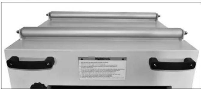
FIG. 3
INSTALLING THE EXTENSION TABLES
Two Extension Tables with three rollers are supplied with the planer to help support lumber as it enters and exits the planer during use. FIG. 4.
- Mount the two extension tables onto each edge of the planer's table (#80) with the three bolts, washers and nuts supplied (#223, 224, 225). Do not fully tighten.
- The rollers on the extension tables should be level with the planer's table. Use a straight edge to align the tables' height with the planer's table.
- Once the extension tables are positioned level with the table, secure them in place by tightening the fasteners (Step 1).
INSTALLING DUST HOSE
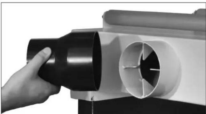
It is extremely important that a dust collection system is used with this planer to eliminate harmful airborne dust, prevent the build-up of chips that may jam the roller system in the cutterhead, and to keep the working area clean of debris.
The planer is supplied with a 4-3/8" dust port which is part of the Upper Cover (#13) assembly. FIG. 5.
A 4-3/8" to 4" Adapter is also supplied to connect flexible 4" dust hose to the planer. Make sure all connections are secure and your dust collector is turned on before any milling of lumber is done.

FIG. 4
natural_image
Close-up of a hand inserting a black cylindrical component into a white cylindrical device (no text or symbols visible)FIG. 5
OPERATION
This machine is intended for surface thickness planing of natural, solid woods. The permissible workpiece dimensions must be observed. Any other use not as specified, including modification of the machine or use of parts not tested and approved by the equipment manufacturer can cause unforeseen damage.
THICKNESSING
NOTE: Thickness planing is used to reduce lumber with one already flattened surface, to a desired thickness.
- The surface that is already milled flat should rest down on the planer bed.
- The lumber is then run through the planer.
- The planer cuts the upper surface of the lumber, so the top surface is flat and parallel with the bottom surface and at a consistent thickness.
WORKPIECE DIMENSIONS
- Length: minimum 8-13/16"; for lumber over 72" use a second person for support, or auxiliary rollers.
- Width: maximum of 16".
- Thickness: minimum of 1/4", maximum 8-13/16".
NOTE: The maximum depth of cut for a single pass is 1/8". For best cutting action and final surface results, it is best to take multiple small cuts of 1/16" or less, rather than deeper cuts, especially on wide boards.
PLANER TABLE HEIGHT ADJUSTMENT
The Hand Wheel controls the height setting for the planer's bed and the final planed thickness of your lumber (thickness of the workpiece after planing).
CAUTION
A maximum of 1/8" material can be removed in one pass through the planer. Do not exceed this depth of cut or damage to your machine may result. The maximum thickness of stock to be planed is 16", and the maximum width of boards is 8-13/16".
-
Height adjustment is made with the hand wheel (FIG. 6, A). One full turn of the hand wheel changes the height of the planer bed (B) by 1/8".
-
Clockwise turning = raises the planer bed.
-
Counter-clockwise turning = lowers the planer bed.
-
The planing thickness is indicated on the Scale (C).
-
After preliminary cuts are made on all of your lumber, and the final thickness is settled, the table can be locked with the Lever (D). This is useful to ensure the setting will not change throughout the planing process, especially if a lot of lumber is to be planed at the same thickness.
PLANER FEED RATE SPEED CHANGE
The feed speeds of this machine can be adjusted by the handle (#155). FIG. 7.
- Start the motor.
- Turn the handle clockwise, the feed speed will be increased.
- Turn the handle counter-clockwise, the feed speed will decrease.
NOTE: The feed speed changing handle only can be operated when the motor is running. DO NOT change the feed speed while a board is being planed. Damage to the machine may result.

FIG. 6
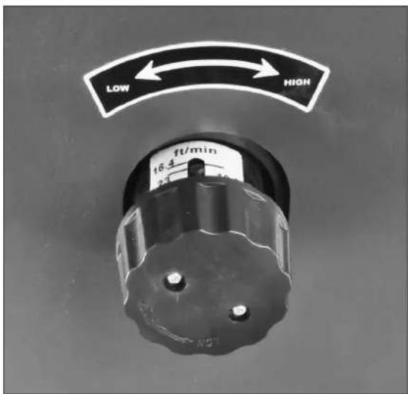
FIG. 7
OPERATION
PLANER OPERATION
Before turning on the planer, review the safety precautions listed on pages 3 to 6, and the operating instructions on pages 6 and 10. Make sure that you fully understand the features, adjustments and capabilities of the machine that are outlined throughout this manual.
-
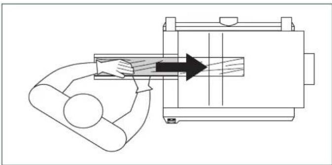
To feed the workpiece into the machine, assume proper operating position, FIG. 8. Stand offset to one side of the feed opening to avoid any kick-back, should it occur. Do not push the lumber once the infeed roller has been engaged. Let the infeed roller move the workpiece into the planer at its own pace.
-
To remove the workpiece from the machine, position yourself offset to one side of the outfeed opening. FIG. 9. Do not pull the lumber as it exits the machine. Let the out-feed roller move the workpiece out of the planer at its own rate, but support the lumber as it extends past the extension rollers, if needed.
-
Do not plane boards that are less than 6" long. Short boards should be planed end to end with other boards to prevent kick-back and snipe.
- Boards longer than 24" should have additional support as they enter and exit the planer, so that they do not tip up or down, causing snipe on the ends.
- Run boards through the planer at different positions along the width of the bed to utilize the full length of the cutting knives. Planing only in the center, or through one side of the planer, will quickly dull the knives in that area.
SNIPE
The term 'snipe' refers to the depression that may occur at the front or rear of a board during planing. It is caused by uneven pressure on the cutterhead when a board is fed into the planer, or when exiting. FIG. 10.
Avoid snipe by keeping your lumber firmly down onto the planer bed at the beginning of the cut, and also at the end of the cutting action, as the lumber exits the planer.
ON/OFF SWITCHES
The planer is equipped with a standard, push button ON/OFF safety switch (#204) located on the right side of the machine. FIG. 11. Push the top green button to start the planer. Push the lower red button to stop the planer.
An additional automatic OFF safety micro-switch (#206) is located under the cover (FIG. 12, A). Should the cover ever be opened, this switch will prevent the machine from operating. NOTE: When working on the planer, the machine should always have the red, OFF button engaged and the cord unplugged from the power source.
natural_image
Diagram of a mechanical device with a person operating it, showing a lever and directional arrow (no text or symbols)FIG. 8

natural_image
Line drawing of a mechanical device with an arrow indicating motion or force, showing a seated person interacting with a device (no text or symbols present)FIG. 9
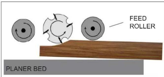
FIG. 10
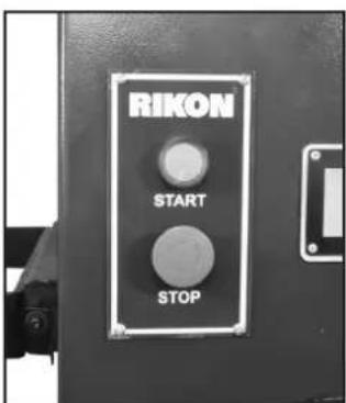
FIG. 11

FIG. 12
ADJUSTMENTS
WARNING
THE MACHINE MUST NOT BE PLUGGED IN AND THE POWER SWITCH MUST BE IN THE OFF POSITION UNTIL ADJUSTMENTS ARE COMPLETE.
ROTATING OR REPLACING KNIFE INSERTS
This machine has a helical cutterhead with four rows of carbide knife inserts. Each of the 72 inserts on the cutterhead are indexed and have four sharpened sides. If the knives become dull, or one becomes nicked, simply loosen the retaining screws with the supplied star head screwdriver, lift up and rotate the inserts to a new sharpened edge. No setting is required, as the cutterhead has been machined to automatically index and set the inserts in proper position for use. When all four sides of an insert are dull, the insert can be easily removed and a new carbide insert placed in the location. To rotate or remove a carbide insert knife:
- Unplug power cable.
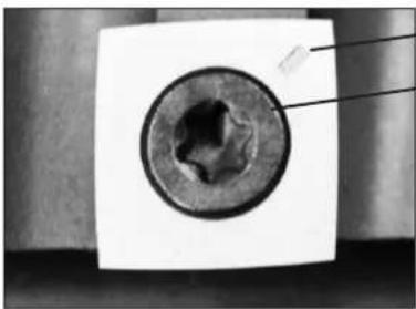
- Remove the Screw (#217), that holds the Insert in the cutterhead, and the Insert knife (#216). FIG. 13.
- While the insert is removed, clean any resin buildup or trapped dust from the surfaces of the cutterhead with a suitable solvent. A tooth brush works well for safe cleaning around the sharp inserts. Any accumulated dust can affect the seating of the insert in the cutterhead.
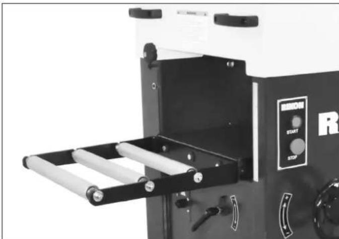
- Rotate the insert so that a new sharpened edge is in position. The inserts have a indication mark on their top surface corner, so that you can reference the positioning of the insert's dulled or sharpened edges. FIG. 13 -16.
- Tighten the insert's set screw to lock the insert back in position. DO NOT overtighten the screw or damage to the insert may result. Torque to 50-55 in/lbs.
- Plug in the power cable when you are ready to resume jointing and planing.
PLANER TABLE ALIGNMENT
The machine has been factory set before shipping - the planer's table being set parallel to the cutterhead knives. But once the machine has been set in its final location in the shop, the table alignment should be checked to make sure that there has been no movement during its handling.
WARNING: When working on, or near the machine's bed, avoid the risk of personal injury by cuts that may result from touching the knife inserts' sharp edges!
natural_image
Close-up of a metallic circular component with a central hole, mounted on a flat surface (no visible text or symbols)INDEX MARK
STAR HEAD
SET SCREW
CARBIDE INSERT
KNIFE HAS 4
SHARP EDGES
FIG. 13
CAUTION
Wear gloves when changing knife risk of personal injury by cuts that ching the sharp edges!

natural_image
Close-up of a mechanical component with four circular features and a metal screwdriver inserted (no visible text or symbols)FIG. 14

natural_image
Close-up of industrial conveyor belts with circular components (no visible text or symbols)FIG. 15
natural_image
Industrial machine with roller mechanism and control panel (no visible text or symbols)FIG. 16
ADJUSTMENTS
Planer Table Alignment continued from page 12
- Make sure that the planer/jointer's switch is turned off, and the plug is disconnected from the power source.
NOTE: The cutterhead is fixed in position and any adjustments of the must be made through the planer table's setting. FIG. 17
-
To confirm that the planer table is set parallel to the cutterhead, measurements from the table surface to the underside of the cutterhead are made. The distance from the far right side of the planer's table should be the same as the distance taken at the far left of the table.
-
Place a Gauge Block (FIG. 18), or other measuring tool, onto the planer table and directly under the cutterhead at one end (Position R).
-
Raise the table until with the hand wheel until the gauge block makes contact with the cutterhead knife inserts, or the solid body of the cutterhead cylinder.
-
Move the gauge block to the other side of the table (Position L) to check to see if the gauge block is at the same measurement. If the distance is not the same, then the planer table has to be adjusted to make up this difference.
NOTE: Since the cutterhead is of a helical design, care must be taken to make the measurements at the same spot on the either end of the head. This may require that the cutterhead be rotated so that the gauge block comes in contact with either the knife inserts or body, same as was used on the first measurement taken.
ADJUSTING THE PLANER TABLE
-
The planer table assembly is attached to the cabinet by four Hex Bolts (#104A, FIG. 19, A). Next to these bolts are four Hex Socket Screws (#104, B) that can be adjusted to raise an end of the planer table so that it will be parallel with the cutterhead.
-
Slightly loosen the four hex bolts at the corners of the base plate.
-
Depending on which side of the planer's table needs to be raised, turn the hex screws at that side of the base to raise the base/table.
-
Repeat measuring with the gauge block and making adjustments until the table is parallel with the cutterhead.
-
Once the table and cutterhead are parallel, tighten the four hex bolts to secure the fasteners in place.
-
Remove the gauge block from the mouth of the planer and check all parts to confirm the machine is ready for use.

FIG. 17

FIG. 18

FIG. 19
ADJUSTMENTS
ADJUSTING THE CUTTERHEAD
The Cutterhead that holds the knife inserts is fastened to the machine's cabinet, and is not adjustable. Based on the position of this main component of the machine, all of the other parts - rollers and tables - are then preset by the factory to align with the cutterhead. Should any of the tables or rollers get out of parallel with the cutterhead, they can be adjusted separately following the instructions in this manual.
NOTE: The Cutterhead's Guard / Chip Breaker (#53, FIG. 20) is also preset by the factory to align correctly with the cutterhead. This guard must never be removed except for adjustments or maintenance purposes to the cutterhead assembly.
The Infeed (#65) and Outfeed (#66) Rollers are preset by the factory to align parallel with the cutterhead and knife inserts. These spring loaded rollers are set just below the cutterhead, so that they engage the lumber and move it through the planer. Should an adjustment be required to increase or decrease the amount of downward pressure they exert on the lumber, the following steps are needed.
- Make sure that the planer's switch is turned off, and the plug is disconnected from the power source.
- Lift the planer's upper Cover (#13) to access the cutterhead assembly. FIG. 21 & 22.
- Adjusting Downward Pressure for the Feed Rollers is done by the Springs (#47, A) positioned above the Roller Shaft ends (C). Adjusting the pressure is done with the Set Screws (#48, B) that are above the springs.
- By raising the hex nuts UP, the spring compression is reduced and the downward pressure on the rollers is decreased upon the lumber being fed through the planer.
- By screwing the hex nuts DOWN more, the spring compression is increased, and the rollers exert more pressure down onto the lumber.
NOTE: For changing of Roller Pressure, adjust the four springs first, as changing the rollers' height (below) may affect the rollers parallel alignment with the cutterhead.
-
Adjusting Feed Roller Height. Under the roller shafts, the Hex Bolts and Nuts (#46, 45, D) can be turned with an offset wrench to raise or lower the feed rollers as needed to remain parallel to the cutterhead or to adjust the roller pressure down on the lumber.
-
By raising the hex bolts UP, the roller height is raised. This will decrease the pressure upon the lumber being fed through the planer.
- By lowering the hex nuts DOWN, the roller height is lowered, and will exert more pressure down onto the lumber.
WARNING THE MACHINE MUST NOT BE PLUGGED IN AND THE POWER SWITCH MUST BE IN THE OFF POSITION UNTIL ALL ADJUSTMENTS ARE COMPLETE.

FIG. 20

FIG. 21

FIG. 22
- Once the rollers are set, unlatch and lower the cover and the machine is ready to be plugged back in for use.
ADJUSTMENTS
ADJUSTING DRIVE BELTS
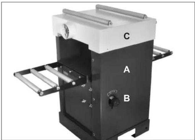
The cutterhead drive belt and the feed gear drive belt need to be checked periodically and re-tightened if necessary. Belts will stretch with use, especially when they are new and are breaking in. Both drive belts are located behind the machine's side panel. FIG. 23, A & B.
WARNING THE PLANER MUST NOT BE PLUGGED IN AND THE POWER SWITCH MUST BE IN THE OFF POSITION UNTIL ADJUSTMENTS ARE COMPLETE.
CHECKING THE DRIVE BELT
- Make sure that the planer's switch is turned off, and the plug is disconnected from the power source.
- Remove the Speed Control Knob (#155, FIG. 23, B)
- Take off the left side panel (#4, FIG. 23, A) by loosening the six hex head screws (#3) that secure the panel to the cabinet, and also lift up the cutterhead cover (#13) to reveal the motor, pulleys and belts.
- Check the drive belt tension with finger/thumb pressure. The drive belt should not deflect more than 3/8" to 1/2" in the center. FIG. 24.
TENSIONING THE DRIVE BELTS
- Check the Cutterhead Drive Belt (#145, FIG. 25, A) tension with thumb pressure. The drive belt should not give more than 3/8" to 1/2" in the center.
- From outside, rear of the machine, loosen the four Nuts (#144, B) that secure the motor in place. Lift the motor to slacken the tension on the drive belt, or move it down to increase the belt tension.
- When the belt tension is correct, tighten the motor mounting nuts that were done in step 4.
- The Feed Roller Belt (#152, C) is automatically tensioned with the wheel bracket Spring (#184, D) and requires no adjustments.
- The Feed Roller Chain (#140, E) is factory set and should not require any setting changes. However, to increase or decrease the chain overlap, the Bearing with Sleeve (#228, F) can be adjusted in or out with the Carriage Bolt & Nut (#131, 135).
NOTE: While the side panel and cutterhead cover are open, remove any chips and dust that may have accumulated with a dust collector or brush.
CAUTION: Keep your hands clear of the sharp knives.
natural_image
Industrial machine with labeled components A, B, and C, showing internal structure and mounting rails (no text or symbols beyond labels)FIG. 23

FIG. 24
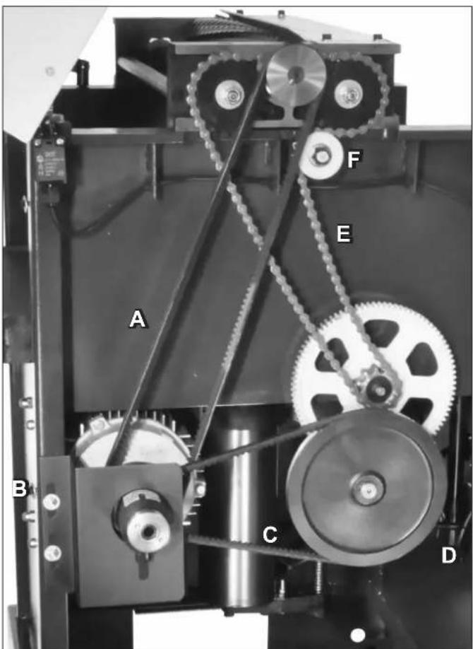
FIG. 25
ADJUSTMENTS
Drive Belt Adjustment continued from page 15
- When all belts have been checked and any maintenance has been done, replace and secure the side panel and speed control knob back to their positions with the screws that were previously removed (In steps 2 & 3).
REPLACING THE DRIVE BELTS
- To replace the Cutterhead Drive Belt (#145, FIG. 26, A), follow the same steps, #2-6 above (page 15) to remove the side panel and access the belts and pulleys. Loosen the tension until both the Cutterhead Drive Belt and the Feed Roller Belt (#152, B) can be easily removed from both their pulleys.
The small Panel (#150, C) that surrounds the speed control arbor must be removed to slide the two used belts off of the motor arbor. Once removed, reverse the steps to install and re-tension the new belts on their pulleys. - To replace the Feed Roller Belt (#152, B), the small Panel (C) must first be removed. With the motor loose and lifted, there should be enough slack to install a new Feed Roller Belt. If not, the tensioning Spring (#184, D) can also be unhooked to allow the Cam Wheel Bracket (#185) to swing loose. Re-fastened the spring once the belt has been installed. Then reverse the steps to install the drive belt and re-tension it on the pulleys.
- When all work on the belts has been done, replace the small panel, cabinet side panel, and the speed control knob and secure them in position with the same screws that were previously removed.
ALIGNING THE PULLEYS
The pulley positions for the belts are preset at the factory for proper alignment to each other. If they are not set correctly, excess wear to the belts and power transfer may be reduced. While the side panel is open, the pulleys should be checked to make sure that no movement has occurred during use.
- With a metal straight edge, or perfectly flat board, place the straight edge against the faces of the two pulleys that are connected by the same belt. FIG. 27.
- If the straight edge does not lie flat on both of the pulley faces, one or both of the pulleys must be moved to correct this miss-alignment.
- Loosen the pulleys' set screws and shift the pulleys along their shafts until they are properly aligned.
- Tighten the pulley set screws and them re-check the belt tension as described on page 15.
WARNING THE PLANER MUST NOT BE PLUGGED IN AND THE POWER SWITCH MUST BE IN THE OFF POSITION UNTIL ADJUSTMENTS ARE COMPLETE.
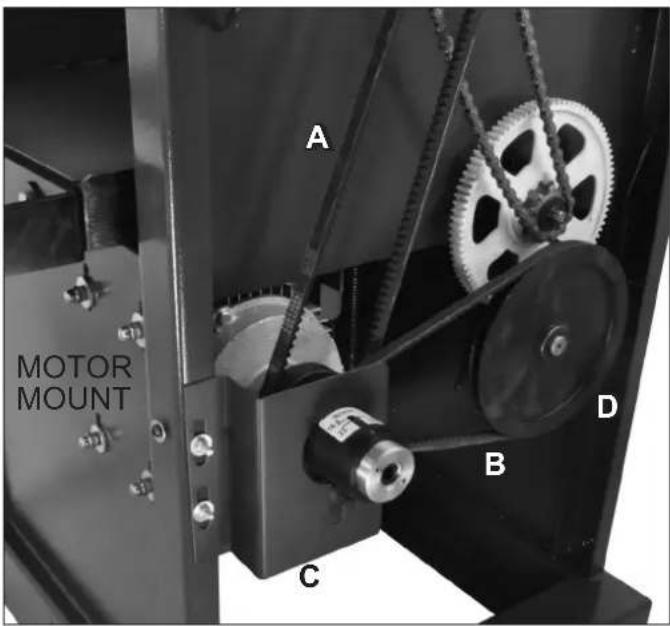
FIG. 26
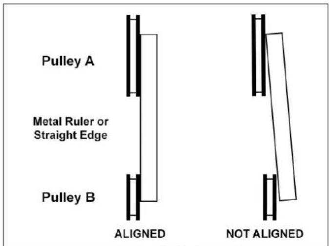
FIG. 27
MAINTENANCE
WARNING:
Turn the power switch "OFF" and disconnect the plug from the outlet prior to adjusting or maintaining the machine.
1. Before each use:
- Check the power cord and plug for any wear or damage.
- Check for any loose screws or hardware.
- Check the area to make sure it is clear of any misplaced tools, lumber, cleaning supplies, etc. that could hamper the safe operation of the planer.
- To avoid a build-up of wood dust, regularly clean all parts of the machine using a soft cloth, brush or compressed air. A general cleaning should be done after every use to avoid future problems and ensure the machine is in ready condition for the next time it is used.
WARNING: If blowing sawdust, wear proper eye protection to prevent debris from blowing into eyes.
Avoid using high pressure near ball bearings seals as this may weaken the seals and allow lubricant to leak out, or force contaminants into the bearing.
- Check the knives to make sure that they are not loose from the cutterhead, dull or nicked. Making sure that they are in proper operating condition will ensure that the quality of your surfaced lumber will be the best possible.
-
Lubricate all bearing points and chains regularly with a few drops of light motor oil. Cutterhead ball bearings are lifetime lubricated, sealed, and do not need any further care. Keep the drive belts free of oil and grease.
-
Clean the planer bed columns on a regular basis to prevent the build-up of wood chips and dust. Treat the posts with a dry lubricant spray. Do not use ordinary oil which will collect dust and hamper the operation of the machine.
- Keep the jointer and planer tables free of resin and rust. Clean them regularly with a non-flammable solvent, then coat with a light film of dry lubricant spray, or wax, to enhance passage of workpiece on/over the tables.
WARNING: When cleaning or working on the tables, avoid the risk of personal injury by cuts that may result from touching the knife inserts' sharp edges! Lower the planer table to its maximum 'down' position, so that there is ample distance between the table and the cutterhead.
- Clean the feed rollers with a soft rag, and non-flammable solvent if there is resin build-up on the metal rollers. Do not apply solvents on a 'rubber' coated roller, as it may affect the material. Be careful to keep hands away from the sharp cutterhead knife inserts. Do not apply any lubricant to the rollers as they must 'grab' the lumber to move it through the planer and so must not slip.
- Check the anti-kickback fingers to make sure that they are clean of any dust or resin, so that they swing freely. Lubricate only with a dry lubricant, never oil or grease.
- Check the belt tension after the first 3-5 hrs. of operation to ensure that the belts have not become stretched and loose from their 'breaking in' use. See page 15 for instructions.
WIRING DIAGRAM
WARNING:
This machine must be grounded. Replacement of the power supply cable should only be a qualified electrician. See page 5 for additional electrical information.


WARNING
FOR YOUR OWN SAFETY, ALWAYS TURN OFF AND UNPLUG THE MACHINE BEFORE CARRYING OUT ANY TROUBLESHOOTING.
| SYMPTOM POSSIBLE CAUSES SOLUTIONS | ||
| Planer will not start. | 1. No power2. Blown fuse3. Main on/off switch or Micro switch in cover is not functioning4. Motor failure | 1. Check power source, plug and wiring.2. Check fuse, replace if it is blown.3. Check position of the switches. Contact local dealer for repair or replacement.4. Inspect motor for failed components. Contact Dealer for repair or replacement. |
| Circuit Breakers trip and /or Fuses are blown | 1. Wrong circuit size for the machine2. Motor is overloaded under strain from taking too heavy of cut | 1. Check circuit/fuse rating and amps of the motor. Install CORRECT rated breaker/fuse.2. Take lighter cuts in planing lumber. |
| Planer feed rate and cutting is not consistent | 1. Belts are loose2. Chips and dust build-up on parts | 1. Check pulleys and belts for tension & wear.2. Unplug planer from power source and clean planer parts. |
| Poor feeding of lumber through the planer | 1. Drive belt is worn or broken2. Drive belt tension spring is broken3. Lumber sticking on planer's table4. Feed rollers not applying enough pressure on lumber | 1. Check and replace as necessary.2. Check tension and/or replace the spring.3. Clean the table and apply silicone based lubricant to reduce friction.4. Adjust the feed roller pressure. |
| Not planing lumber to a uniform thickness | 1. Planer table is not level to cutterhead | 1. Adjust table and/or cutterhead as needed. |
| 'Chatter' marks on planed lumber | 1. Feed rate is too fast 1. Slow the feed rate down | |
| Small raised lines are running along the surface | 1. Knives are nicked or broken 1. Rotate insert knives to new sharp edges. | |
| Snipe on board ends(NOTE: Snipe can be reduced, but not fully eliminated) | 1. Feed rollers not set properly2. Lumber not supported when fed into or exiting the planer3. Short boards not butted | 1. Adjust feed roller height for applying pressure onto lumber to keep flat on table.2. Support long boards with roller stands.3. Run boards butt end to end through planer |
| Planned surface is torn | 1. Cutting against the grain2. Cut is too deep3. Knives are dull | 1. Cut with the grain. For figured woods, take shallow cuts to minimize tear out.2. Reduce cutting depth to 1/16" or less.3. Rotate insert knives to new sharp edges. |
| Planned surface grain is rough, raised or fuzzy | 1. Lumber has a high moisture content2. Knives are dull | 1. Reduce the moisture content by drying it, or switch to other properly seasoned lumber.2. Rotate insert knives to new sharp edges. |
| Planned surface is glossy | 1. Cutting depth is too shallow2. Knives are dull3. Feed rate is too slow | 1. Increase depth of cut slightly.2. Rotate insert knives to new sharp edges.3. Increase feed rate. |
For parts or technical questions contact: techsupport@rikontools.com or 877-884-5167.
CUTTERHEAD ASSEMBLY

other
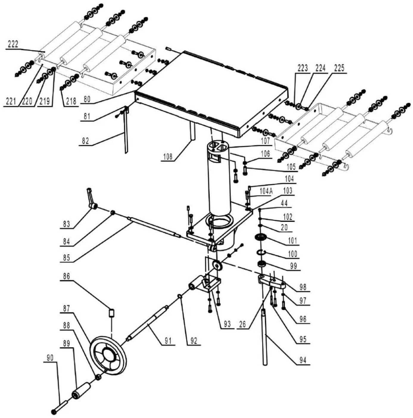
| KEY NO. | DESCRIPTION | MFG. PART NO. | | ------- | ---------- | ------------- | | 41 | Flat Washer 10 | P23-400-41 | | 42 | Hex Bolt M10x25 | P23-400-42 | | 43 | Flat Washer 6 | P23-400-43 | | 44 | Screw M6x12 | P23-400-44 | | 45 | Hex Nut M8 | P23-400-45 | | 46 | Hex Bolt M8x12 | P23-400-46 | | 47 | Spring | P23-400-47 | | 48 | Screw | P23-400-48 | | 49 | Retaining Ring | P23-400-49 | | 50 | Wave Washer 52 | P23-400-50 | | 51 | Bearing 6205 | P23-400-51 | | 52 | Set Screw M6x12 | P23-400-52 |TABLE ASSEMBLY
KEY NO.
DESCRIPTION
MFG. PART NO.
| 20 | Flat Washer 8 | P23-400-20 |
| 26 | Hex Nut M6 | P23-400-26 |
| 44 | Screw M6x12 | P23-400-44 |
| 80 | Thickness Table | P23-400-80 |
| 81 | Indicator | P23-400-81 |
| 82 | Scale | P23-400-82 |
| 83 | Lock Handle | P23-400-83 |
| 84 | Hex Nut M10 | P23-400-84 |
| 85 | Locking Bar | P23-400-85 |
| 86 | Set Screw M8x16 | P23-400-86 |
| 87 | Crank Handwheel | P23-400-87 |
| 88 | Hex Nut M10 | P23-400-88 |
| 89 | Handle | P23-400-89 |
| 90 | Handle Bolt | P23-400-90 |
| 91 | Crank Bar | P23-400-91 |
| 92 | Retaining Ring | P23-400-92 |
| 93 | Bevel Gear Bracket | P23-400-93 |
| 94 | Thread Rod | P23-400-94 |
| 95 | Screw M6x40 | P23-400-95 |
| 96 | Hex Bolt M8x35 | P23-400-96 |
| 97 | Spring Washer | P23-400-97 |
| 98 | Thread Rod Bracket | P23-400-98 |
| 99 | Bearing 80202 | P23-400-99 |
| 100 | Retaining Ring 35 | P23-400-100 |
| 101 | Bevel Gear | P23-400-101 |
| 102 | Flat Washer 6 | P23-400-102 |
| 103 | Column Support | P23-400-103 |
| 104 | Set Screw M8x20 | P23-400-104 |
| 104A | Hex Bolt M8x40 | P23-400-104A |
| 105 | Hex Bolt M10x35 | P23-400-105 |
| 106 | Spring Washer 10 | P23-400-106 |
| 107 | Column | P23-400-107 |
| 108 | Guide Bar | P23-400-108 |
| 218 | Cap Nut | P23-400-218 |
| 219 | Hex Nut | P23-400-219 |
| 220 | Washer | P23-400-220 |
| 221 | Side Table Support | P23-400-221 |
| 222 | Side Table Roller | P23-400-222 |
| 223 | Flat Washer | P23-400-223 |
| 224 | Flat Washer | P23-400-224 |
| 225 | Hex Bolt | P23-400-225 |
NOTE: Please reference the Manufacturer's Part Number when calling for Replacement Parts. For Parts under Warranty, the Serial Number of your machine is required.
MFG. PART NO.
| P23-400-163 |
| P23-400-164 |
| P23-400-165 |
| P23-400-166 |
| P23-400-167 |
| P23-400-168 |
| P23-400-169 |
| P23-400-170 |
| P23-400-171 |
| P23-400-172 |
| P23-400-173 |
| P23-400-174 |
| P23-400-175 |
| P23-400-176 |
| P23-400-177 |
| P23-400-178 |
| P23-400-179 |
| P23-400-180 |
| P23-400-181 |
| P23-400-182 |
| P23-400-183 |
| P23-400-184 |
| P23-400-185 |
| P23-400-186 |
| P23-400-187 |
| P23-400H-226 |
| P23-400H-227 |
| P23-400H-228 |
| P23-400H-229 |
| P23-400H-230 |
KEY NO.
| 163 | Tube |
| 164 | Scale |
| 165 | Bearing 6005 |
| 166 | Retaining Ring 47 |
| 167 | Sliding Pulley |
| 168 | Set Screw M8x8 |
| 169 | Motor Pulley |
| 170 | Retaining Ring 18 |
| 171 | Pulley |
| 172 | Retaining Ring 42 |
| 173 | Bearing Seat |
| 174 | Retaining Ring 20 |
| 175 | Bearing 80104 |
| 176 | Key 4x12 |
| 177 | Pulley Shaft |
| 178 | Small Gear |
| 179 | Retaining Ring 12 |
| 180 | Retaining Ring 10 |
| 181 | Retaining Ring 15 |
| 182 | Pulley Tube |
| 183 | Pulley |
| 184 | Spring |
| 185 | Wheel Bracket |
| 186 | Hex Bolt M8x20 |
| 187 | Pulley Shaft |
| 226 | Base Plate |
| 227 | Washer |
| 228 | Wheel |
| 229 | Tube |
| 230 | Retaining Ring |
DESCRARTONO.
| P23-400-131 |
| P23-400-134 |
| P23-400-135 |
| P23-400-136 |
| P23-400-137 |
| P23-400-138 |
| P23-400-139 |
| P23-400-140 |
| P23-400-141 |
| P23-400-141A |
| P23-400-142 |
| P23-400-143 |
| P23-400-144 |
| P23-400-145 |
| P23-400-146 |
| P23-400-147 |
| P23-400-148 |
| P23-400-149 |
| P23-400-150 |
| P23-400-151 |
| P23-400-152 |
| P23-400-153 |
| P23-400-155 |
| P23-400-156 |
| P23-400-157 |
| P23-400-158 |
| P23-400-159 |
| P23-400-160 |
| P23-400-161 |
| P23-400-162 |
DESCRIPTION
| 131 | Carriage Bolt M12x70 |
| 134 | Bearing 80203 |
| 135 | Hex Nut M12 |
| 136 | Washer |
| 137 | Chain Wheel |
| 138 | Flat Washer 10 |
| 139 | Lock Nut M10 |
| 140 | Chain |
| 141 | Motor |
| 141A | Capacitor (not shown) |
| 142 | Flange Bolt M8x25 |
| 143 | Flat Washer 8 |
| 144 | Cap Nut M8 |
| 145 | Drive Belt |
| 146 | Spindle Pulley |
| 147 | Key 6x16 |
| 148 | Set Screw M8x6 |
| 149 | Hex Bolt M6x16 |
| 150 | Panel |
| 151 | Cable Tube |
| 152 | Drive Belt |
| 153 | Pan Head Screw |
| 155 | Adjusting Knob |
| 156 | Adjusting Nut |
| 157 | Hex Socket Head Screw |
| 158 | Position Bar |
| 159 | Bearing 80101 |
| 160 | Retaining Ring 28 |
| 161 | Retaining Ring 25 |
| 162 | Set Screw M6x8 |
KEY NO.
NOTE: Please reference the Manufacturer's Part Number when calling for Replacement Parts. For Parts under Warranty, the Serial Number of your machine is required.
CABINET & CONTROLS
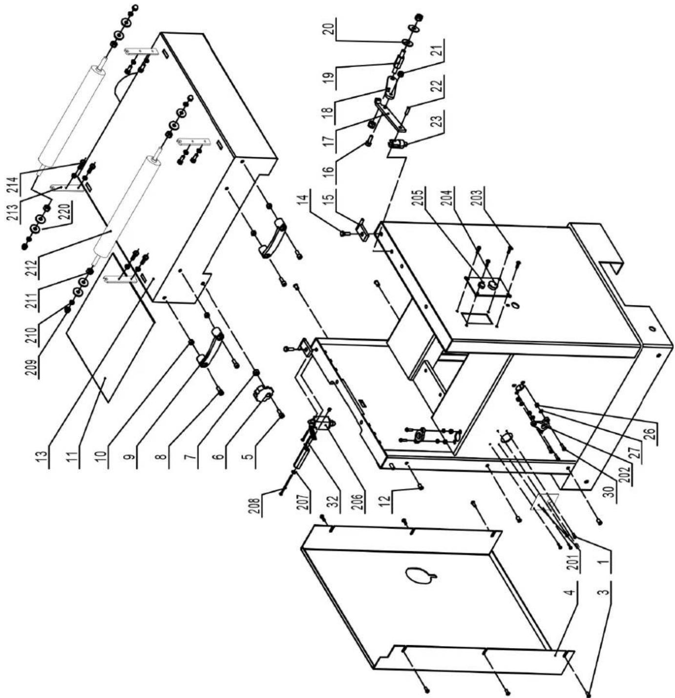
MFG. PART NO.
KEY NO.
KEY NO. MFG.DEASCRNPOJON
| 1 | Pan Head Screw M4x8 | P23-400-1 | 23 | Support Shaft | P23-400-23 |
| 3 | Hex Screw M6x16 | P23-400-3 | 26 | Hex Nut M6 | P23-400-26 |
| 4 | Side Panel | P23-400-4 | 27 | Flat Washer 6 | P23-400-27 |
| 5 | Screw M10x25 | P23-400-5 | 30 | Set Screw M6x20 | P23-400-30 |
| 6 | Lock Knob | P23-400-6 | 32 | Pan Head Screw M4x35 | P23-400-32 |
| 7 | Lock Nut M10 | P23-400-7 | 201 | Switch Plate | P23-400-201 |
| 8 | Screw M8x30 | P23-400-8 | 202 | Ring | P23-400H-202 |
| 9 | Handle | P23-400-9 | 203 | Pan Head Screw | P23-400-203 |
| 10 | Lock Nut M8 | P23-400-10 | 204 | On/Off Switch | P23-400-204 |
| 11 | Insulating Foam | P23-400-11 | 205 | Switch | P23-400-205 |
| 12 | Nut M6x15 | P23-400-12 | 206 | Micro Switch | P23-400-206 |
| 13 | Upper Cover | P23-400-13 | 207 | Flat Washer | P23-400-207 |
| 14 | Hex Bolt M10x25 | P23-400-14 | 208 | Pan Head Screw | P23-400-208 |
| 15 | Bracket | P23-400-15 | 209 | Cap Nut | P23-400-209 |
| 16 | Hex Bolt M6x20 | P23-400-16 | 210 | Spring Washer | P23-400-210 |
| 17 | Support Bracket I | P23-400-17 | 211 | Hex Nut | P23-400-211 |
| 18 | Support Bracket II | P23-400-18 | 212 | Roller | P23-400-212 |
| 19 | Shaft | P23-400-19 | 213 | Roller Support | P23-400-213 |
| 20 | Flat Washer 8 | P23-400-20 | 214 | Hex Bolt | P23-400-214 |
| 21 | Lock Nut M6 | P23-400-21 | 220 | Washer | P23-400-220 |
| 22 | Roll Pin 5x16 | P23-400-22 |
NOTE: Please reference the Manufacturer's Part Number when calling for Replacement Parts. For Parts under Warranty, the Serial Number of your machine is required.
RIKON
POWER TOOLS
5-Year Limited Warranty
RIKON Power Tools Inc. ("Seller") warrants to only the original retail consumer/purchaser of our products that each product be free from defects in materials and workmanship for a period of five (5) years from the date the product was purchased at retail. This warranty may not be transferred.
This warranty does not apply to defects due directly or indirectly to misuse, abuse, negligence, accidents, repairs, alterations, lack of maintenance or normal wear and tear. Under no circumstances will Seller be liable for incidental or consequential damages resulting from defective products. All other warranties, expressed or implied, whether of merchantability, fitness for purpose, or otherwise are expressly disclaimed by Seller. This warranty does not cover products used for commercial, industrial or educational purposes.
This limited warranty does not apply to accessory items such as blades, drill bits, sanding discs, grinding wheels or belts and other related items.
Seller shall in no event be liable for death, injuries to persons or property, or for incidental, contingent, special, or consequential damages arising from the use of our products.
To take advantage of this warranty proof of purchase documentation, which includes date of purchase and an explanation of the complaint, must be provided.
The Seller reserves the right to effect at any time, without prior notice, those alterations to parts, fittings, and accessory equipment which they may deem necessary for any reason whatsoever.
To take advantage of this warranty, please fill out the enclosed warranty card and send it to: RIKON Warranty
16 Progress Rd.
Billerica, MA 01821
The card must be entirely completed in order for it to be valid. If you have any questions please contact us at 877-884-5167 or warranty@rikontools.com.
ACCESSORIES

natural_image
A curved arrangement of eight black square tiles with circular holes, arranged in a symmetrical pattern (no text or symbols)25-599 Replacement Carbide Inserts - PK 10
4-Sided, pre-sharpened carbide insert knives measure 0.59" x 0.59" x 0.10". Pack of 10.
25-594 Mounting Screws for Inserts - PK 10
Special flat head, T25 Star drive screws for mounting insert cutters onto cutterheads.
Visit www.rikontools.com to review RIKON's line of professional machinery and accessories.
NOTES
Use this section to record maintenance, service and any calls to Technical Support:

For more information:
16 Progress Road
Billerica, MA 01821
877-884-5167 / 978-528-5380
techsupport@rikontools.com
- 16" Thickness Planer with Helical Cutterhead
- Operator's Manual
- TABLE OF CONTENTS
- SPECIFICATIONS
- SAFETY INSTRUCTIONS
- SAFETY SYMBOLS
- DANGER
- WARNING
- CAUTION
- GENERAL SAFETY
- BEFORE USING YOUR MACHINE
- ELECTRICAL SAFETY
- EXTENSION CORDS
- WARNING:
- REPLACE A DAMAGED OR WORN CORD IMMEDIATELY.
- WARNING Keep the text
- SPECIFIC SAFETY INSTRUCTIONS FOR PLANERS
- SAVE THESE INSTRUCTIONS.
- Refer to them often.
- California Proposition 65 Warning
- GETTING TO KNOW YOUR MACHINE
- CONTENTS OF PACKAGE
- Tools for Assembly & Adjustments
- ASSEMBLY
- THE PLANER MUST NOT BE PLUGGED IN AND THE POWER SWITCH MUST BE IN THE OFF POSITION UNTIL ASSEMBLY IS COMPLETE.
- Unpacking and Clean-up
- INSTALLING THE PLANER
- INSTALLING THE HAND WHEEL
- INSTALLING THE EXTENSION TABLES
- INSTALLING DUST HOSE
- OPERATION
- THICKNESSING
- WORKPIECE DIMENSIONS
- PLANER TABLE HEIGHT ADJUSTMENT
- PLANER FEED RATE SPEED CHANGE
- PLANER OPERATION
- SNIPE
- ON/OFF SWITCHES
- ADJUSTMENTS
- ROTATING OR REPLACING KNIFE INSERTS
- PLANER TABLE ALIGNMENT
- Planer Table Alignment continued from page 12
- ADJUSTING THE PLANER TABLE
- ADJUSTING THE CUTTERHEAD
- ADJUSTING DRIVE BELTS
- CHECKING THE DRIVE BELT
- TENSIONING THE DRIVE BELTS
- REPLACING THE DRIVE BELTS
- ALIGNING THE PULLEYS
- MAINTENANCE
- Before each use:
- WIRING DIAGRAM
- FOR YOUR OWN SAFETY, ALWAYS TURN OFF AND UNPLUG THE MACHINE BEFORE CARRYING OUT ANY TROUBLESHOOTING.
- CABINET & CONTROLS
- RIKON
- POWER TOOLS
- 5-Year Limited Warranty
- ACCESSORIES
- NOTES
Brand : RIKON
Model : 23-400H
Category : Planer