
EVMAGU23X-3 - Power strip Tripp Lite - Free user manual and instructions
Find the device manual for free EVMAGU23X-3 Tripp Lite in PDF.


| Product Type | Surge Protected Power Strip |
| Model | EVMAGU23X-3 |
| Brand | Tripp Lite |
| Dimensions (H x W x D) | 1.5 x 4 x 12 inches |
| Weight | 1.2 lbs |
| Input Voltage | 120V AC |
| Maximum Current | 15A |
| Maximum Power | 1800W |
| Surge Protection Rating | 1200 Joules |
| Number of Outlets | 6 |
| Cord Length | 6 feet |
| Warranty | Lifetime Limited Warranty |
| Key Features | EMI/RFI filtering, right-angle plug, keyhole mounting slots |
| Safety Certifications | UL 1449, cUL, NOM |
| Cleaning | Wipe with dry cloth; unplug before cleaning |
| Repairability | No user-serviceable parts; do not open |
Frequently Asked Questions - EVMAGU23X-3 Tripp Lite
User questions about EVMAGU23X-3 Tripp Lite
0 question about this device. Answer the ones you know or ask your own.
Ask a new question about this device
Download the instructions for your Power strip in PDF format for free! Find your manual EVMAGU23X-3 - Tripp Lite and take your electronic device back in hand. On this page are published all the documents necessary for the use of your device. EVMAGU23X-3 by Tripp Lite.
USER MANUAL EVMAGU23X-3 Tripp Lite
Rack PDU G3 EVMAGU23X-3
Installation and Setup Manual
Eaton reserves the right to change specifications without prior notice. Eaton is a registered trademark of Eaton. All other trademarks are properties of their respective companies. All other trademarks are property of their respective companies.
©Copyright 2023 Eaton, Raleigh, NC, USA. All rights reserved. No part of this document may be reproduced in any way without the express written approval of Eaton.
TTaabbllee ooff CCoonntteennttss
1 Introduction....1
1.1 Description....1
1.2 Product Specifications .... 2
1.3 Eaton Rack PDU Models 2
1.4 Circuit Protection....3
1.5 Power Outlets ...... 4
1.6 Input Power Cord 5
1.7 Accessories....5
2 Installation 7
2.1 Safety Warnings....7
2.2 Installation 8
2.3 Installation Precautions....8
2.4 Inspecting the Equipment....8
2.5 Package Contents....9
2.6 Optional Environmental Monitoring Probe 10
2.7 Installation Overview....11
2.8 Tools....11
2.9 Configurations ...... 11
2.10 Power Feed Labels.... 12
2.11 Installation and Mounting Buttons 12
2.11.1 Installing Vertical Rack PDUs in a Rack Cabinet.... 13
2.11.2 Using Factory-installed Mounting Buttons 13
2.11.3 Using Flush-style Mounting Buttons.... 13
2.11.4 Grounding the Rack to the Rack PDU 14
2.12 Quick Start for Universal Input Rack PDU 14
2.13 Connecting the Output Devices 17
3 Service....19
3.1 Service and Support 19
3.2 Warranty....19
Table of Contents
The Eaton® Enclosure Power Distribution Unit (Rack PDU®) G3 EVMAGU23X-3 is an intelligent Rack PDU that is designed to distribute power within a standard 19-inch rack. A wide range of models let you connect and manage a variety of outlets from a single power connection. Most models have monitoring or switching capabilities, or both.
Figure 1 and show examples of installed G3 EVMAGU23X-3 Eaton Rack PDUs.
Figure 1. Example Rack PDU G3 EVMAGU23X-3 Installations

natural_image
Technical illustration of a server rack unit with visible internal components and wiring (no text or symbols)The Rack PDU G3 family provides six different Rack PDU topologies. The monitoring or switching capabilities are characterized as follows:
- Basic (BA) with no monitoring or intelligent controls
- In-Line Metered (IL) with monitoring at the input
- Metered Input (MI) with monitoring at the input and branch
- Metered Outlet (MO) with monitoring at the input, branch, and individual outlet monitoring, but no outlet control
- Switched (SW) with control of outlets but no individual outlet monitoring
- Managed (MA) with monitoring at the input, branch, and individual outlet control and monitoring

NOTE These capabilities are expressed in the model numbers of the Rack PDUs.
Table 1 shows which main features are implemented or not implemented, depending on the topology:
Table 1. Monitoring and Management Features Available for Rack PDU Topologies
| Models | Input Metering | Branch Metering Outlet Metering | Outlet Switching | Environmental Sensor Monitoring | ||
| Basic (BA) | — — — — — | |||||
| In-Line Metered (IL) | ● — — — ● | |||||
| Metered Input (MI) | ● ● | — — ● | ||||
| Metered Outlet (MO) | ● ● | ● — ● | ||||
| Switched (SW) | ● ● | — ● | ● | |||
| Managed (MA) | ● ● | ● ● | ● | |||
NOTE Environmental sensor monitoring is only available if an Environmental Monitoring Probe (EMP) is attached.
1.2 Product Specifications
Find product specifications, diagrams, part number and ordering matrix documents, and marketing collateral at Eaton.com/ePDU/G3
1.3 Eaton Rack PDU Models
The Rack PDU models support single-phase and three-phase applications and have 8 to 54 outlets. Network-connected models feature an LCD display and LEDs to indicate status on communication connectors. Metered Outlet, Switched, and Managed models contain LEDs to indicate outlet status. Most Rack PDUs have attached power cords and circuit breakers (see Eaton.com/ePDU/G3).

NOTE Select models have detachable input power cords.
Figure 2. Example Rack PDU G3 EVMAGU23X-3 Product
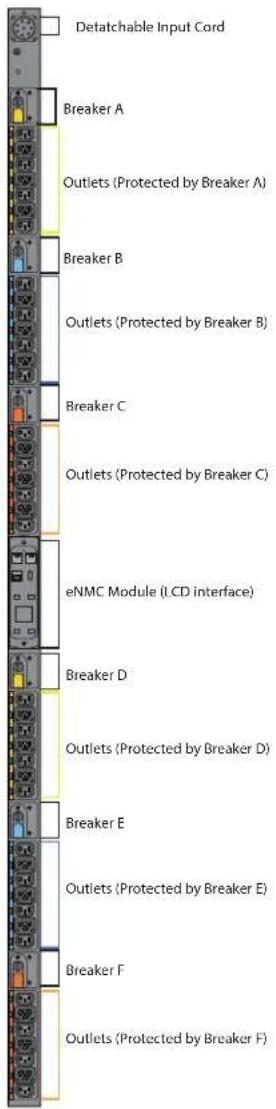
Circuit breakers activate if the load current rating of an outlet section exceeds 16A (Europe) / 20A (US). Power to the outlet turns off automatically. To reset the circuit breaker, turn the breaker from Off to On.

NOTE 1 The On/Off positions are indicated on the circuit breakers.
NOTE 2 To manually disconnect power to a device that is connected to the Rack PDU, disconnect the device power cord from the Rack PDU outlet.
NOTE 3 To disconnect power on models without a circuit breaker, disconnect the Rack PDU input power cord.
Figure 3 shows circuit protection device examples.
Figure 3. Circuit Protection Devices

natural_image
Three 3D mechanical component diagrams showing progressive assembly from base to top, with no visible text or symbols.11..55 PPoowweerr 00uuttleettss
Each model has a specific configuration of standard NEMA outlets, IEC 60320 and IEC 60309 outlets, EMEA national types (French, Schuko, and UK), or other outlet types. Many configurations are available or the configurations can be customized to match your needs.
The outlets are grouped in sets called sections. Outlet sections are preset groups of individual outlets that you can identify and monitor through the different interfaces that are available with the Rack PDU.
The outlets are color-coded and labeled. If the model has circuit breakers, the circuit breakers that are associated with the outlets have corresponding labels (see Figure 4).
You can connect one device to each outlet.
Figure 4. Example Outlet Types

Rack PDU G3 EVMAGU23X-3 model has both IEC 60320 C13 outlets, as well as a proprietary Eaton C39 combination outlet. This C39 outlet is a combination of C13 and C19 outlet styles, and it is designed to accept both C14 and C20 plugs.
PDUs with these outlets are also designed to have native high-retention, which makes it more difficult for the plug to be removed. When removal of a plug is necessary, wiggle it from side to side while pulling on it.
Figure 5. C39 High Retention Outlet Option

Use the input power cords to connect to the power source. Input power cords are permanent for most models. Select models have detachable input power cords.
1.7 Accessories
The Environmental Monitoring Probe (EMP) accessory is optional and must be purchased separately. The optional EMP provides monitoring of external temperature, humidity, and the status of two contact devices, providing greater power management control and flexible monitoring. The EMP has the following features:
- Simplified installation lets you install the EMP safely without turning off power to the Rack PDU or to the devices that are connected to it.
- The EMP monitors temperature and humidity information of any environment, protecting your critical equipment. The EMP measures temperatures between 0°C and 70°C (32°F and 158°F) with an accuracy of ±2°C. The EMP measures relative humidity between 10% and 90% with an accuracy of ±5%.
- The EMP can be located away from the Rack PDU with a Category 5 network cable up to 50m (165 ft) long.
• The EMP monitors the status of two user-supplied contact devices.
• Temperature, humidity, and contact closure status can be displayed through a variety of interfaces. - User-selectable alarm thresholds let you define acceptable temperature or humidity limits.
- You can use e-mail client software to set up e-mail notification through Simple Network Management Protocol (SNMP) when acceptable alarm limits are exceeded or contact status changes.
• Changes in external contact status are logged in the Rack PDU event history log. - When temperature and humidity values exceed user-selectable limits, the event is logged in the Rack PDU event history log.

NOTE
For information updates, refer to the Eaton Rack PDU catalog or go to Eaton.com/ePDU/G3.
Accessories
Important Safety Instructions — Save These Instructions
This manual contains important instructions that you should follow during installation and operation of the Eaton Rack Power Distribution Unit (PDU) G3 EVMAGU23X-3. Please read all instructions before operating the equipment and save this manual for future reference. Failure to follow these instructions may result in severe injury or death.
Detailed specifications are available on our Web site at Eaton.com/ePDU/G3
DANGER — Risk of Electric Shock
This PDU contains hazardous voltages. All repairs and service must be performed by authorized service personnel only. There are no user serviceable parts. Systems should only be installed, tested, and configured by a qualified electrical worker.
This equipment must be connected to an earthed mains socket-outlet, or to an electrical supply that has a protective earthing conductor.
CAUTION — Risk of Fire
• If this PDU has a input power plug:
– The installation power outlet should be tested for proper polarity and earthing.
- The installation power outlet used to power this equipment must be installed near the equipment and the plug must be easily accessible.
– The equipment plug is the disconnect device. Remove the plug from the outlet to isolate the PDU.
- This product must be protected by a branch circuit protection device with a rating according to the product's plug rating.
• If this PDU is permanently connected:
– An all-pole disconnect device must be provided in the building installation.
– To isolate this PDU, turn off the disconnect switch.
This product must be protected by a branch circuit protection device with a rating in accordance with the product's input rating.
- This product must be removed from service when there is evidence (e.g., a tripped circuit breaker) that it has been overloaded or that a load electrical fault has occurred. Do not return the product to service until it has been thoroughly evaluated by a qualified electrical worker.
Notice
- To reduce the risk of equipment damage, install this PDU in a temperature and humidity controlled, non-corrosive, indoor environment, that is free of conductive contaminants. Do not operate near water or excessive humidity (95% maximum non-condensing).
- Both the room and rack air temperature must be within the operating range of the selected model.
- Only use supplied PDU mounting hardware and accessories. If necessary, contact your customer service representative for replacement parts.
- This product has been designed to conform to the latest safety requirements. In addition to compliance with standards of general use, it has been factory configured for use in rack mounting environments, aiding the installer in providing system compliance with relevant standards.
The Eaton Power Distribution Unit (Rack PDU) G3 EVMAGU23X-3 model is mounted vertically inside rack structures. Use the information in this chapter to prepare, install, and connect the Rack PDU and optional accessories.
Before you install or connect the Rack PDU in a rack cabinet, observe the following precautions:
- Only a competent service person should install, test, or configure the Rack PDU and its optional accessories. It is the installer's responsibility to ensure that the selected product is installed to meet national and local safety regulations.
- Read and understand all warnings and cautions listed in 2.1 Safety Warnings.
- Review the documentation that comes with your rack cabinet for safety and cabling information. Follow all installation and operation safety information provided.

NOTE Removing the rack cabinet doors and side panels might make installation easier. See the rack cabinet documentation for more information.
- Verify that the room and rack air temperature is within the operating range of the selected model.
• Take all necessary precautions to handle the weight of the devices. - Connect all power cords to properly wired and grounded electrical outlets.
CAUTION
The installation power outlet used for the power supply to this equipment must be installed near the equipment and must be easily accessible.
- Do not overload the power outlet when you install multiple devices in the rack cabinet.
- To reduce the risk of fire, connect only to a circuit provided with branch circuit overcurrent protection with an A (ampere) rating in accordance with the NEC (National Electrical Code), ANSI/NFPA 70 or your local electrical code.
- Verify that all equipment is unplugged from Rack PDU outlets before performing any testing.
- For units without circuit breakers, the Rack PDU output power cannot be turned on and off with a button or switch. These Rack PDUs are always on when they are plugged in. These Rack PDUs are always off when they are unplugged.
-
For units with circuit breakers, the circuit breaker controls whether there is output power:
-
If the circuit breakers are on, there is output power, the LCD display is on, and the network communications module is operational.
- If the circuit breakers are off, there is no output power, but the LCD display is on, and the network communications module is operational.
- To turn off the Rack PDU, unplug it.
22..44 Ilnnssppeeccttiinngg tthhee EEqquuiippmeenntt
If any equipment has been damaged during shipment, keep the shipping cartons and packing materials for the carrier or place of purchase, and file a claim for shipping damage. If you discover damage after acceptance, file a claim for concealed damage.
To file a claim for shipping damage or concealed damage: 1) File with the carrier within 15 days of receipt of the equipment; 2) Send a copy of the damage claim within 15 days to your service representative.
Contents vary with each model and region of purchase. To verify contents, refer to the Quick Start Guide supplied with your Rack PDU.
Figure 6. Example Shipping Carton and Contents (as shown on the supplied Quick Start Guide)
22..55 PPaacckkaaggee CCoonntteennttss
Figure 7. PDU Package Contents

natural_image
Illustration of electronic components including a rectangular device, coiled cable, and various electronic devices with no visible text or symbols.Table 2 lists the accessory parts that are included in the shipping carton with Rack PDU EVMAGU23X-3. Table 3 lists parts supplied for use with the G3 communication card.
Table 2. Shipped with the Rack PDU in the Shipping Carton — Replacement SPK045
| Quantity | Description | |
| 1 | Eaton Rack G3 EVMAGU23X-3 PDU Installation and Connectivity Quick StartContains details for how to install the Rack PDU |  |
| 1 | Eaton Rack G3 EVMAGU23X-3 PDU Safety GuideContains important safety information |  |
| 2 | (1) Red and (1) Blue Source LabelsThese can be applied to the PDU to indicate the power feed |  |
| 2 | (1) Red and (1) Blue Wrapping LabelsThese 75x100mm labels can be applied to the PDU powercord to indicate the power feed |  |
| 2 | Flush Mounting ButtonsThese double-sided 2mm/3mm buttons allow the PDU to be installed with the least rack interference |  |
| 2 | M4 x 10mm flathead screwsExtra screws for the flush mounting buttons |  |
| 1 | Ethernet cable, Cat 5e, 150mm lengthUsed either for network cascading between adjacent PDUs or initial PDU configuration |  |
Table 3. Shipped with Rack PDU G3 EVMAGU23X-3 with the G3 Communication Card - Replacement SPK013
| Quantity Description | ||
| 1 | Ethernet Cable, 600mm, ShieldedUsed for Ethernet or daisy-chain connections |  |
| 1 | Serial Cable, DB9 to RJ45Used for RS232 set up or KVM connections |  |
| 1 | BP8C "Y" SplitterCan be installed in the daisy-chain port and used for daisy-chaining up to eight PDUs |  |
2.6 Optional Environmental Monitoring Probe
Optional Environmental Monitoring Probe (EMP) equipment with sensors can be connected to the Rack PDU as an accessory. The equipment is customer-supplied and should be installed using the manufacturer's instruction manual.

IMPORTANT
Follow all installation and operation safety information provided in the manufacturer's instruction manual for the EMP equipment. Use only supplied accessories.
NOTE 1 Power cords for the devices that you connect to the Rack PDU are not included.
NOTE 2 Depending on your choice of installation method, some parts may not be used.
NOTE 3 Use only the supplied screws for installation. Hand tighten the screws. Do not overtighten to avoid stripping the screws.

IMPORTANT
Use great care in handling the Rack PDU during installation. Avoid unnecessary contact between the Rack PDU and the rack.
22..88 TToooolss
The Rack PDU G3 EVMAGU23X-3 is designed to be mounted without the use of tools. Mounting buttons are pre-installed on the rear of the PDU at the factory. If you wish to use a different mounting option, such as an adapter bracket or side mounting, tools are not provided, but may be required as follows:
- For vertical installations:
- Phillips cross-head screwdriver
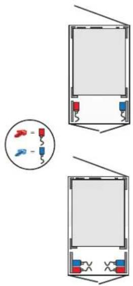
You can install one or two Rack PDUs vertically on each side of the rack (see Figure 8).
Figure 8. Vertical Rack PDU Configurations
22..1100 PPoowweerr FFeeeedd LLaabbeellss
Adhesive power feed labels (red power feed arrow and blue power feed arrow) are supplied to allow identification of the power flow for up to two individual Rack PDUs. The customer can choose the location of the sticker in an available space on the unit or the rack. Adhere one to the side of an Rack PDU at your discretion to indicate the power feed direction (see Figure 9).
Colored wrapping labels are also included for use on the Rack PDU's input cord. If two G3 EVMAGU23X-3 PDUs are in a rack and connected to different feeds, then two red and two blue wrapping labels will be available for each PDU. These wrapping labels could be placed near the plug as well as near the PDU.
Figure 9. Power Feed Labels

natural_image
3D rendering of a server rack cabinet with visible internal components and mounting holes (no text or labels)2.11 Installation and Mounting Buttons

NOTE
Only use the provided screws to mount the buttons.
The mounting buttons for 0U vertical Rack PDUs are factory installed. These pre-installed buttons are shoulder-style and are well-suited for all standard rack-mount applications. In particular it is designed to work well with Eaton rack enclosures with 11.5-12.5mm diameter slots and 1.5-2mm thick material, as well as TrippLite by Eaton 2-post and 4-post racks with 14mm diameter slots and 3mm thick material.
Additionally, the accessory kit includes two flush-style buttons. These buttons allow a PDU to be mounted so that it touches the mounting surface, thus saving some PDU depth. They are reversible, with one side designed for 1.5-2mm rack material thickness, and the other side designed for 3mm rack material thickness.
The screws for these buttons are flat-head, M4 x 10mm. Only the provided screws should be used to mount the buttons.
Regardless of the configuration you choose, there are two mounting methods available for installing the Rack PDU vertically in a rack cabinet:
- Using factory-installed shoulder-style buttons on the Rack PDU to mount it in keyhole openings in the rack frame.
- Using flush-style buttons on the Rack PDU to mount it in the keyhole openings in the rack frame.
Review the installation methods described in this section and choose the method appropriate for your environment.
To install the Rack PDU with the factory-installed shoulder-style mounting buttons:
- Carefully move the Rack PDU into position against the rail.
- Insert the top and bottom mounting buttons into the keyhole slots on the rack post that correspond with the position of the top and bottom mounting buttons.
- Push down to secure the Rack PDU in position (see).

NOTE
The Rack PDU will fit tight and it may require minor force to engage in the slot. This is a friction fit to hold the Rack PDU in the slot.
To install the Rack PDU with the flush-style mounting buttons from the accessory kit:
- Unscrew and remove the factory-installed shoulder-style buttons.
- Locate the flush buttons from the accessory kit.
- Orient the flush buttons to either the 2mm or 3mm side depending on the rack material thickness.
Figure 10. Reversing the Mounting Buttons
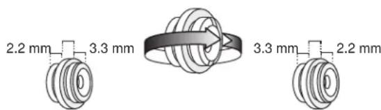
- Secure the flush-style buttons to the Rack PDU using the provided screws.
- Carefully move the Rack PDU into position against the rail.
- Insert the top and bottom mounting buttons into the keyhole slots on the rack post that correspond with the position of the top and bottom mounting buttons.
- Push down to secure the Rack PDU in position

NOTE
The Rack PDU will fit tight and it may require minor force to engage in the slot. This is a friction fit to hold the Rack PDU in the slot.
Figure 11. Securing the Rack PDU

natural_image
Diagram showing a vertical panel with cable and a side panel with holes, connected by wires (no text or symbols)22..1111..44 GGroouunnddiinngg tthhee RRaacckk ttoo tthhee RRaacckk PPDDUU

NOTE Grounding the Rack PDU is optional but recommended.
The Rack PDU is grounded through the input plug and an M6 ground screw is provided for auxiliary rack grounding. Conductors can be connected to the ground screw for functional grounding or bonding of ungrounded metal parts within the rack. The grounding screw is sized to safely conduct the fault current of the single largest output breaker. There is no paint on the screw or the chassis surface to ensure contact with bare metal instead of a painted surface. The ground symbol is marked in the chassis adjacent to the earth bonding screw.
To ground the Rack PDU, connect a grounding cable (not supplied) from earth to the grounding screw shown in Figure 12. The internal diameter of the ground strap ring is M6 (6 mm).
Figure 12. Grounding Screw Location for 0U Vertical Models

natural_image
Illustration of a screwdriver and a mechanical device with a yellow cable, showing no text or symbols.2.12 Quick Start for Universal Input Rack PDU
Eaton Universal Input Rack PDUs are a highly versatile solution for meeting the challenges of powering today's IT equipment. These Rack PDUs feature a special input connector that can be used with a variety of cordsets, including 1-phase, 3-phase delta 208V, 3-phase wye 120/208V, and 3-phase wye 240/415V. The power rating of the PDU is based on the input cordset used, as detailed in Table 4. These cordsets are sold and shipped separately from the PDU.
Step 1: Choose a CordSet
Cordsets should be selected via Table 4 based on the required power for the rack system, and the available receptacle to plug into.
Only Eaton cordsets having a Regulatory Model beginning with "EZ1" should be used with Eaton's Universal Input Rack PDUs.
Step 2 : Connect the CordSet to the PDU
To connect the cordset to the PDU:
- Rotate the cordset connector until the white line aligns with the large slot slot on the PDU connector.
- While keeping the cordset connector straight, insert the cordset connector as far as it will go into the PDU connector.
Figure 13. Align Cordset

- Rotate the metal ring on the cordset connector clockwise to secure it to the PDU. Hand-tighten only.
Figure 14. Tighten CordSet

natural_image
3D diagram of a cable connector with a green arrow indicating rotation, no text or symbols presentStep 3: Connect the Cordset to a Power Source
Most cordsets have a plug, and they should be connected to a matching receptacle.
A few cordsets have pigtails. These can be wired directly into an electrical junction box or busway tap-off box. This connection must be performed by a qualified electrical worker in conformance with local electrical codes. Note that the PDU+cordset connector pair is rated by UL and IEC as a disconnect device.
Step 4: Power-On and Configure the PDU
Apply power to the PDU.
For EVMAGU23X-3 with G3 PDU network card, the PDU input measurement mode needs to be configured in order to have proper display of input measurements and alarms. This configuration is done using the following steps. See the communication quick-start for details on how to make a connection and log in.
To use the web interface:
- On the Overview webpage, click the Settings menu in the bottom right corner.
- In the Power Input Mode box, choose the option based on the table below

-
Set the input current high warning and critical thresholds to match the input plug and desired alarm levels.
-
Save the changes and reboot.
To use the SSH or serial interface:
- Set the Power Input Mode using the following command: set PDU.Input[1].Setting.Mode x where 'x' is 1, 2, or 3 (choose the correct value from the table below):
1: 1-Phase
2: 3-Phase Delta 208V
3: 3-Phase Wye 230/400V
The Power Input Mode setting should be selected based on the cordset see Table 4.
- Reboot the PDU using the following command:
set system.restart 1
Table 4. CordSet Options
| Part Number | Plug Type Input Voltage | Power Input | Mode | Current Certifications | Regulatory Model |
| CBL350-10 NEMA | L6-30P | 1P, 200-240V | 1-Phase 24A cRUus | EZ1-MT3N | |
| CBL351-10 NEMA | L21-30P | 3P Wye, 120/208V | 3-Phase Delta 208V* | 24A cRUus EZ1-PD | 4S |
| CBL352-10 | IEC 60309 332P6, IP44 1P, | 230V | 1-Phase 32A | CE/IEC | |
| CBL353-10 | IEC 60309 516P6, IP44 | 3P Wye, 230/400V | 3-Phase Wye 230/400V | 16A | CE/IEC |
| CBL354-10 | IEC 60309 332P6W, IP67 | 3P Wye, 240/415V | 1-Phase | 24A UL (32A CE) | cRUus, CE/IEC |
| CBL355-10 | IEC 60309 516P6W, IP67 | 3P Wye, 240/415V | 3-Phase Wye 230/400V | 16A | cRUus, CE/IEC |
| CBL356-10 | IEC 60309 460P9W, IP67 3P | Delta, 208V | 3-Phase Delta 208V | 48A cRUus EZ1-FL | 4U |
| CBL357-10 | Pigtails | 3P Delta, 208V | 3-Phase Delta 208V | 55A (70A panel breaker) | cRUus EZ1-4U |
| CBL358-10 | IEC 60309 532P6W, IP67 | 3P Wye, 240/415V | 3-Phase Wye 230/400V | 24A UL (32A CE) | cRUus, CE/IEC |
| CBL359-10 | IEC 60309 532P6, IP44 | 3P Wye, 230/400V | 3-Phase Wye 230/400V | 32A | CE/IEC |
| CBL360-10 | IEC 60309 560P6W, IP67 | 3P Wye, 240/415V | 3-Phase Wye 230/400V | 32A cRUus EZ1-FU | 5Y |
| CBL362-10 | IEC 60309 360P6W, IP67 1P, | 240V | 1-Phase 48A cRUus | EZ1-EL3Q | |
| CBL363-10 | IEC 60309 363P6, IP67 1P, | 230V | 1-Phase 63A | CE/IEC | |
| CBL364-10 CS8865 | 3P Delta, 208V | 3-Phase Delta 208V | 40A cRUus EZ1-PH | 4U | |
| CBL365-10 NEMA | L15-30P | 3P Delta, 208V | 3-Phase Delta 208V | 24A cRUus EZ1-PD | 4S |
| CBL366-10 | IEC 60309 560P9W, IP67 | 3P Wye, 120/208V | 3-Phase Delta 208V* | 48A cRUus EZ1-FF | 4U |
| * Note: While these plugs are 120/208V 3-Phase Wye, the neutral connection is not used in the cordset or PDU. The Input Power Mode should therefore be selected as 3-Phase Delta 208V. | |||||
2.13 Connecting the Output Devices
The Rack PDU outlets are available for connecting and monitoring devices such as workstations, servers, and switches. Connect a device you want to monitor to a power outlet on the Rack PDU with the power cord that comes with the device.

NOTE
You may find it useful to document the connections you make.
To connect your devices:
- Verify that each circuit breaker is in the On position.
-
For Rack PDUs with detachable power cords. If the power cord is not connected, connect the power cord to the Rack PDU. Otherwise, go to Step 3.
-
Route the Rack PDU power cord toward a dedicated power source. If desired, use cable ties to secure the power cord as needed. If the power cord must exit the rack cabinet to connect to a power source, use the openings in the rack cabinet.

NOTE 1 Plug the Rack PDU into an appropriately rated outlet for its type.
NOTE 2 Do not replace or rewire the power cord.
- Connect the power cord to a properly wired and grounded dedicated power source. The Rack PDU turns on and displays an Eaton startup screen while starting. After a period of inactivity, the LCD screensaver will begin cycling through different screens.
- Connect your output devices to the outlets on the Rack PDU. Verify that each device is receiving power before connecting the next device.

NOTE To avoid large surge currents, connect the protected equipment to the outlets individually rather than as a group. You may want to include a delay for Switched and Managed models when setting up groups of outlets to start at the same time to avoid a large in-rush current.
- Route all power cords neatly. If desired, use cable ties to secure the cords.
CChhaapptteerr 33 SSeerrvviiccee
3.1 Service and Support
If you have any questions or problems with the Eaton Enclosure Power Distribution Unit (Rack G3 PDU EVMAGU23X-3), call your Local Distributor or the Help Desk at one of the following telephone numbers and ask for an Rack PDU technical representative:
| United States: | 1-800-356-5737 |
| Canada: | 1-800-461-9166 ext 260 |
| All other countries: | Call your local service representative |
Please have the following information ready when you call for service:
- Model number
- Serial number
• Date of failure or problem
• Symptoms of failure or problem
- Customer return address and contact information
provides the Eaton catalog part number for ordering optional and spare parts for the Rack PDU. Contact your local service representative for more information.
Table 5. Optional and Spare Parts
| Eaton Catalog Number | Optional or Spare Part | Americas/APAC Market | EMEA/APAC Market | Description |
| EMPDT1H1C2 | Optional | • | • | Eaton Environmental Monitoring Probe |
| SUB-HRDW-3007 | Spare Part | • | eNMC Module Replacement Pack (Americas) | |
| SPK045 | Spare Part | • | — | Rack PDU G4 Installation Spare Pack (Americas) |
| SPK013 | Spare Part | • | — | ePDU G3 Communication Card cables Spare Pack |
Please visit Eaton.com to view the limited warranty for rackmount Rack PDUs.
- TTaabbllee ooff CCoonntteennttss
- Introduction....1
- Installation 7
- Service....19
- Product Specifications
- Eaton Rack PDU Models
- 11..55 PPoowweerr 00uuttleettss
- Accessories
- NOTE
- Important Safety Instructions — Save These Instructions
- DANGER — Risk of Electric Shock
- CAUTION — Risk of Fire
- Notice
- CAUTION
- 22..44 Ilnnssppeeccttiinngg tthhee EEqquuiippmeenntt
- 22..55 PPaacckkaaggee CCoonntteennttss
- Optional Environmental Monitoring Probe
- IMPORTANT
- 22..88 TToooolss
- 22..1100 PPoowweerr FFeeeedd LLaabbeellss
- Installation and Mounting Buttons
- 22..1111..44 GGroouunnddiinngg tthhee RRaacckk ttoo tthhee RRaacckk PPDDUU
- Quick Start for Universal Input Rack PDU
- Step 1: Choose a CordSet
- Step 2 : Connect the CordSet to the PDU
- Step 3: Connect the Cordset to a Power Source
- Step 4: Power-On and Configure the PDU
- To use the web interface:
- To use the SSH or serial interface:
- Connecting the Output Devices
- CChhaapptteerr 33 SSeerrvviiccee
- Service and Support
Brand : Tripp Lite
Model : EVMAGU23X-3
Category : Power strip