
Form 1 - Heating Nectre - Free user manual and instructions
Find the device manual for free Form 1 Nectre in PDF.


| Product Type | Freestanding Wood Heater |
| Brand | Nectre |
| Model | Form 1 |
| Dimensions (H x W x D) | 800 x 450 x 400 mm |
| Weight | 95 kg |
| Heat Output (Nominal) | 8 kW |
| Fuel Type | Seasoned hardwood logs |
| Flue Outlet Diameter | 150 mm |
| Efficiency | 78% |
| Emissions (g/kg) | 1.2 g/kg (PM10) |
| Firebox Capacity | 0.06 m³ |
| Maximum Log Length | 450 mm |
| Construction Material | Steel body with cast iron door |
| Safety Features | Cool-to-touch handle, spark screen, overheat protection |
| Cleaning Tools Included | Ash pan, flue brush |
| Installation Type | Freestanding with proper hearth and flue |
| Warranty | 10 years on firebox, 1 year on parts |
| Certification | AS/NZS 4013:2014 |
| Spare Parts Availability | Through authorized dealers |
| Recommended Maintenance | Annual flue cleaning, inspect door seal |
Frequently Asked Questions - Form 1 Nectre
User questions about Form 1 Nectre
0 question about this device. Answer the ones you know or ask your own.
Ask a new question about this device
Download the instructions for your Heating in PDF format for free! Find your manual Form 1 - Nectre and take your electronic device back in hand. On this page are published all the documents necessary for the use of your device. Form 1 by Nectre.
USER MANUAL Form 1 Nectre
natural_image
Black portable stove burner with visible flame inside, no text or symbols present
Form 1
INSTALLATION INSTRUCTIONS
Australian Home Heating
Association Inc.

Glen Dimplex Australia proudly supports the activities of Landcare Australia through its membership of the AHHA.
VERSION 1.0
TABLE OF CONTENTS
- Important Information.... 2
- Installing the Heater.... 2
2.1. Positioning the Heater.... 2
2.1.1. Standard Installation.... 3
2.1.2. Corner Installation.... 3
2.2. Floor Protector (Hearth) 4
- Reducing Clearances to Combustibles..... 4
- Installing the Flue 5
- Installing the Flue (Continued) 6
5.1. Fitting Flue Seal.... 6
- Baffle Plate.... 6
- Installing Vermiculite Lining.... 7
- Outside Air Connection.... 8
- Technical Drawings 9
THE INSTALLATION INSTRUCTIONS IN THIS MANUAL APPLY TO THE NECTRE FORM 1.
IT HAS BEEN TESTED FOR EMISSIONS AND EFFICIENCY AND COMPLIES ACCORDING TO AS/NZS 4012 & AS/NZS 4013.
IT HAS ALSO BEEN TESTED FOR SAFETY INSTALLATION CLEARANCES IN ACCORDANCE WITH AS/NZS 2918:2018.
1. IMPORTANT INFORMATION
Most building regulatory authorities in Australia require any wood heater installation to comply with Installation Standard AS/NZS 2918. Different states and councils may have varying regulations. Check local building regulations before installing the appliance.
All Nectre wood heaters have been tested to ensure that they will meet the appropriate safety Standard requirements if the instructions in this manual are followed. As the safety and emissions performance can be affected by altering the appliance, no modifications are allowed without written permission from the manufacturer.
WE RECOMMEND THAT THE INSTALLATION OF YOUR NECTRE WOOD HEATER BE CARRIED OUT BY A QUALIFIED INSTALLER.
WARNING: THE APPLIANCE AND FLUE SYSTEM SHALL BE INSTALLED IN ACCORDANCE WITH AS/NZS 2918 AND THE APPROPRIATE REQUIREMENTS OF THE RELEVANT BUILDING CODE OR CODES.
WARNING: APPLIANCES INSTALLED IN ACCORDANCE WITH THIS STANDARD SHALL COMPLY WITH THE REQUIREMENTS OF AS/NZS 4012 & AS/NZS 4013 WHERE REQUIRED BY THE REGULATORY AUTHORITY, I.E. THE APPLIANCE SHALL BE IDENTIFIABLE BY A COMPLIANCE PLATE WITH THE MARKING 'TESTED TO AS/NZS 4012 & AS/NZS 4013'.
ANY MODIFICATION OF THE APPLIANCE THAT HAS NOT BEEN APPROVED IN WRITING BY THE TESTING AUTHORITY IS CONSIDERED TO BE IN BREACH OF THE APPROVAL GRANTED FOR COMPLIANCE WITH AS/NZS 4012 & AS/NZS 4013.
Caution: Mixing of appliance or flue-system components from different sources or modifying the dimensional specification of components may result in hazardous conditions. Where such action is considered, the manufacturer should be consulted in the first instance.
Caution: Cracked and broken components, e.g. glass panels or ceramic tiles, may render the installation unsafe.
2. INSTALLING THE HEATER
2.1. POSITIONING THE HEATER
First review the necessary minimum clearances specified before considering where to position the heater. These clearances can be greater if desired.
Also check the practicability of installing the flue system in relation to any obstructing roof beams before positioning the heater.
These clearance distances can only be reduced if the surrounding walls are made of non-combustible material, e.g. stone, brick, or concrete. Alternatively, shielding of the wall(s) can reduce clearances (refer to next section for more detail).
2.1.1. STANDARD INSTALLATION

2.1.2. CORNER INSTALLATION

CLEARANCES
STANDARD INSTALLATION
Side - S1550mm
Side - S2 700mm
Rear - R1100mm
Rear - R2 250mm
Floor - F 300mm
CLEARANCES
CORNER INSTALLATION
Corner - C1300mm
Corner - C2 450mm
Floor - F 300mm
2.2. FLOOR PROTECTOR (HEARTH)
Unless the heater will be standing on a heat resistant floor such as concrete slab with slate or tiles, it will be necessary to provide a floor protector (hearth).
The dimensions given on the previous page ("2.1.
Positioning the Heater") are the minimum required for the floor protector to extend beyond the firebox door opening. It must extend no less than 300 mm in front of the door opening, no less than 200mm both sides of the door opening, and extend under the heater.
MEASUREMENT WIDTH
Door opening width 194mm
Minimum floor protector width 594mm
It may be desirable, e.g. for aesthetic reasons, for the floor protector to be larger than these minimum dimensions.
The floor protector must be no less than 5mm thick, and constructed of non-combustible material in accordance with AS/NZS 2918.
The floor protector may be laid directly on the combustible floor.
For more details and variations on floor protectors refer to AS/NZS 2918 Clause 2.2, 3.3.1, & 3.3.2
3. REDUCING CLEARANCES TO COMBUSTIBLES
If it is necessary to install a heater closer to a combustible surface than the stated requirements in Section 2 of this Installation Guide, it must be done in accordance with Australian Standard AS/NZS 2918 Section 3, Tables 3.1 & 3.2.
Shield Construction: The shield shall be constructed from a heat resistant material. The shield must be fixed to the surface that requires protection and NOT the heater.
The Standard allows three options to reduce stated clearances.
Single layer of continuous material with Minimum Air Gap of 12mm—Clearance Factor = 0.40
Single layer of continuous material with Minimum Air Gap of 25mm—Clearance Factor = 0.30
Two spaced layers of continuous material with Minimum Air Gaps of 12mm + 12mm—Clearance Factor = 0.20
The shielding must be open at the top and bottom (vented) to allow a continuous air flow. It is this air flow that keeps the surface requiring protection cool. Fixings should not impede this air flow.
The shielding needs to go far enough along and up the wall so that the original side and rear required clearances are not compromised. As the flue is now closer to the wall the shielding should also protect the wall from the flue pipe.
For example:
Side wall clearance for the Form 1 is 550mm.
A 12mm gapped shield on the wall with a factor of 0.40.
Calculate: 550mm x 0.40 = 220mm. This is the new side wall minimum clearance.
The shielding needs to be large enough so that none of the original clearances of 550mm are compromised.
4. INSTALLING THE FLUE
The Nectre Form 1 has been tested in accordance with AS/NZS 2918 with a ventilated double cased flue system compliant with clause 4.5.1.2 of the standard.
If installed with an alternative flue system, then the flue system must be tested to AS/NZS 2918 Appendix F and have a letter of opinion from the accredited testing authority stating that flue system can be installed on this heater.
Glen Dimplex is only liable for that which has been tested.
If installed with any anything besides a ventilated double cased flue system, it is the liability of the installer to ensure the installation is compliant with AS/NZS 2918.
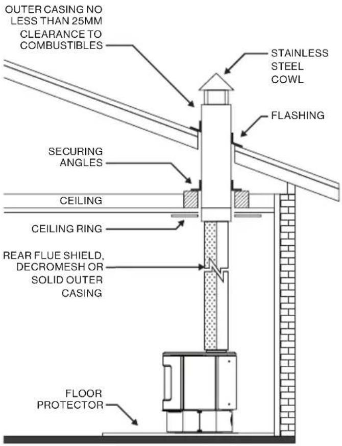
Full instructions on the installation of the flue will be supplied with the flue kit. These MUST be followed closely, including the minimum exit height from the top of the floor protector being not less than 4.6m, and the minimum exit height above the roof line or roof ridge as detailed in the instructions.
The flue must be fitted with one of the following:
- Rear Flue Shield:
a. 900 mm long, minimum 160° arc, stainless steel painted black rear flue shield with 25mm gap between it and the 150mm diameter active flue.
• Decromesh / Solid Flue Shield:
a. Note - must be installed with ventilated locating ring at base of flue shielding.
b. A full length, half radius perforated decromesh flue shield extending from the heater through into the drop box penetrating the ceiling with the perforated surface facing the front, OR equivalent in solid outer flue shield casing (7.75" diameter)
c. The manufacturer's 'locating ring' must be used to support the flue shielding up off the heater top. It is important that air can be drawn into the base and rear of the flue shielding.
d. Place the locating ring above the flue spigot (resting on the top plate) and then place the first length of 150mm active flue into the spigot. Slide the shielding over the active flue. Locate the bottom of the decromesh or solid outer shield inside the locating ring.
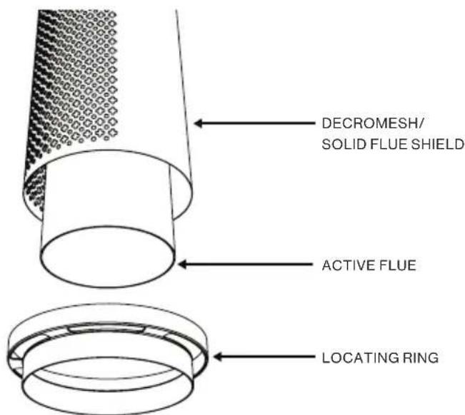
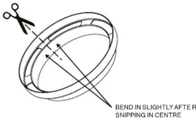
e. Depending on the supplier, the flue shielding can be one of three sizes – 200 mm, 7¾ inch, or 8 inch diameter. The locating ring will fit the two smaller diameters but not the 8 inch. In this scenario, snip through the outer ring with tin-snips as shown in the drawing below. Bend the two “arms” in a little so they ends don’t project out when fitted to the decromesh. Ensure that the snipped section is at the rear of the flue, out of sight.
5. INSTALLING THE FLUE (CONTINUED)
5.1. FITTING FLUE SEAL
Any gaps between the inside of the flue spigot and the active flue should be sealed. This can be done by wrapping the bottom of the flue with a length of fibreglass tape. Alternatively, high temperature stove cement can also be used.
For easier access to flue spigot, Form 1's cast iron top plate can be lifted up approximately 200mm and supported from below while sealing any gaps between the flue spigot and the active flue..
6. BAFFLE PLATE
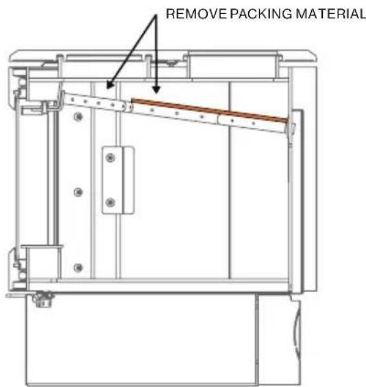
The baffle plate is installed from the factory, and sits atop the burn tubes at the top of the firebox.
It will be packed with material to ensure it doesn't get damaged during transit - ensure this material is removed during heater installation.
Once packing material is removed, ensure baffle is pushed to the rear of the firebox.
7. INSTALLING VERMICULITE LINING
Place the vermiculite bricks into the firebox as shown in the diagram below. Ensure vermiculite bricks are placed in the order listed below.
- Two large bricks with one angled edge - one on either side of the firebox. Place angled edge towards the back of the firebox, and slide towards the front to tuck behind brick retainers bolted to sides of firebox.
- Two medium bricks with two angled edges - one on either corner of the firebox. Ensure angled cut meets up neatly with side bricks.
- One small brick at the rear - this should slot right into place. Ensure that holes in rear brick line up with holes cut into rear of firebox - place the brick with holes to the bottom.
Once bricks are in, fit the retainer over the top to hold them in place.

8. OUTSIDE AIR CONNECTION
Nectre Form 1 has the ability to be connected to an outside air kit. This enables the heater to draw air for combustion completely from outside your home.
This is especially useful in modern, air-tight homes with high energy ratings, but can be done in any house if desired.
The front cover of Nectre Form 1 can be removed with a 4mm hex key. This will enable access to the air intake point - a 75mm diameter tube. Connect outside air ducting here.
The rear cover of Form 1 has a circular knock out that can be removed with tin snips to allow 75mm diameter semi rigid ducting to be routed under the heater and connected.
A Nectre Form Series Outside Air Kit is sold separately.

natural_image
Technical line drawing of a mechanical device with an orange component and directional arrow (no text or symbols)9. TECHNICAL DRAWINGS


Glen Dimplex Australia Pty Ltd
8 Lakeview Drive,
Scoresby Victoria 3179
Australia
T: 1300 556 816 | F: 1800 058 900
General and Sales Enquiries: flame@glendimplex.com.au
Technical Service: service@glendimplex.com.au
www.glendimplex.com.au
- Form 1
- INSTALLATION INSTRUCTIONS
- Australian Home Heating
- TABLE OF CONTENTS
- THE INSTALLATION INSTRUCTIONS IN THIS MANUAL APPLY TO THE NECTRE FORM 1.
- IMPORTANT INFORMATION
- WE RECOMMEND THAT THE INSTALLATION OF YOUR NECTRE WOOD HEATER BE CARRIED OUT BY A QUALIFIED INSTALLER.
- INSTALLING THE HEATER
- POSITIONING THE HEATER
- STANDARD INSTALLATION
- CORNER INSTALLATION
- CLEARANCES
- STANDARD INSTALLATION
- CORNER INSTALLATION
- FLOOR PROTECTOR (HEARTH)
- MEASUREMENT WIDTH
- REDUCING CLEARANCES TO COMBUSTIBLES
- INSTALLING THE FLUE
- - Rear Flue Shield:
- • Decromesh / Solid Flue Shield:
- INSTALLING THE FLUE (CONTINUED)
- FITTING FLUE SEAL
- BAFFLE PLATE
- INSTALLING VERMICULITE LINING
- OUTSIDE AIR CONNECTION
- TECHNICAL DRAWINGS
- Glen Dimplex Australia Pty Ltd
Brand : Nectre
Model : Form 1
Category : Heating