Ω - Dishwasher Noble - Free user manual and instructions
Find the device manual for free Ω Noble in PDF.


| Product Type | Dishwasher |
| Brand | Noble |
| Model | Ω |
| Dimensions (W x D x H) | 60 cm x 60 cm x 85 cm |
| Weight | 45 kg |
| Capacity | 14 place settings |
| Energy Class | A+++ |
| Water Consumption per Cycle | 9.5 L |
| Energy Consumption per Cycle | 0.92 kWh |
| Noise Level | 44 dB |
| Number of Programs | 6 |
| Programs | Eco, Intensive, Normal, Quick, Glass, Auto |
| Additional Functions | Half Load, Delay Start, Turbo Drying |
| Basket Material | Stainless steel |
| Installation Type | Built-in |
| Admissible Water Pressure | 0.05 - 1 MPa |
| Voltage | 220-240 V |
| Frequency | 50 Hz |
| Maximum Power | 2100 W |
| Cable Length | 1.5 m |
| Supply Hose Length | 1.5 m |
| Drain Hose Length | 2.0 m |
| Warranty | 2 years |
| Repairability Index | 8.0 / 10 |
| Spare Parts Availability | Yes |
Frequently Asked Questions - Ω Noble
User questions about Ω Noble
0 question about this device. Answer the ones you know or ask your own.
Ask a new question about this device
Download the instructions for your Dishwasher in PDF format for free! Find your manual Ω - Noble and take your electronic device back in hand. On this page are published all the documents necessary for the use of your device. Ω by Noble.
USER MANUAL Ω Noble
INSTALLATION, OPERATION, AND SERVICE MANUAL
NOBLE C SERIES
C-44
C-54
C-66
C-76
C-80
C-90
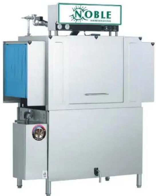
natural_image
Exterior view of a modern industrial water purifier with a large white chamber and green 'NOBLE' logo (no readable text beyond branding)REVISION HISTORY
| Revision Letter | Revision Date | Made by Applicable ECNs Details | |
| A 10-25-16 JH N/A Initial release of manual. | |||
| B 8-18-17 JH 8509 | Updated manual to new format.Audited manual and made corrections throughout.Changed C-44/54 Drain Plumbing Assembly. | ||

C-44CE ^1 , C-54CE, C-66CE, C-76CE, C-80CE, C-90CE
Electrically-heated rack conveyor machines, available in chemical-sanitizing and hot-water-sanitizing models.
C-44CS, C-54CS, C-66CS, C-76CS, C-80CS, C-90CS
Steam-heated, hot-water-sanitizing rack conveyor machines.
SIDE-LOADER OPTION
Conveys a dish rack from the scrapping table to the dishmachine. No additional installation is required and no additional connections must be made.
^1 The number in the model designation is the width of the machine in inches.
The manufacturer provides technical support for all of the dishmachines detailed in this manual. We strongly recommend that you refer to this manual before making a call to our technical support staff. Please have this manual open when you call so that our staff can refer you, if necessary, to the proper page. Technical support is not available on holidays.
Contact technical support toll free at 1-888-800-5672.
Technical support is available for service personnel only.
TABLE OF CONTENTS
GUIDES
Symbols....1
Abbreviations & Acronyms....1
SPECIFICATIONS
Machine Dimensions 2
Side-loader Dimensions....14
Steam Booster Dimensions....17
Operating Parameters 18
Electrical Requirements....19
INSTALLATION
Installation Instructions 23
Inspection.... 23
Unpacking 23
Leveling....23
Plumbing 23
Drain Line....24
Steam Line Connections 24
Plumbing Check.... 24
Electrical Power Connections 24
Ventilation 25
Thermostats 25
Chemical Feeder Equipment 25
Curtains....26
OPERATION
Operating Instructions....27
Preparation 27
Power Up 27
First Rack....28
Ware Preparation 28
Washing a Rack of Ware 28
Operational Inspection 28
Shutdown 29
Cleaning 29
Deliming 31
MAINTENANCE
Preventative Maintenance.... 32
Torque Settings 32
Drive Gear Reducer Lubrication.... 33
TABLE OF CONTENTS
TROUBLESHOOTING
Common Problems 35
PARTS
C-44/54 Control Box 37
C-66/76/80/90 Control Box 39
Motor Overloads 41
Heater Box....43
Pre-wash Inlet Plumbing 47
Solenoid Valve & Vacuum Breaker 48
Rinse Inlet Plumbing 49
Steam Coil 51
Steam Plumbing, L-R....52
Steam Plumbing, R-L....53
C-44/54 Drain Plumbing 54
C-66/76/80/90 Drain Plumbing, L-R 55
C-66/76/80/90 Drain Plumbing, R-L 56
Drain Quench System 57
Motor 58
Pre-wash & Wash Pumps....60
Lower Wash Arm 61
Pre-wash Arm & Upper Wash Arm....62
Final Rinse 63
Doors....64
Drive Assembly 65
Pawl Bar Roller Bracket....67
C-44/66 Pawl Bars....68
C-80 Pawl Bar 69
C-44 Rack Rails 70
C-66 Rack Rails 71
C-80 Rack Rails 72
Strainers....73
Rinse Fill Option....74
Side-loader Parts....75
Miscellaneous Parts 77
TABLE OF CONTENTS
SCHEMATICS
C-44/54CE 208-230 V/50-60 Hz/1-Phase 81
C-44/54CE 460 V/50-60 Hz/3-Phase....82
C-44/54CS 208-230 V/50-60 Hz/1-Phase 83
C-44/54CS 460 V/50-60 Hz/3-Phase....84
C-66/76/80/90CE 208-230 V/50-60 Hz/1-Phase 85
C-66/76/80/90CE 460 V/50-60 Hz/3-Phase....86
C-66/76/80/90CS 208-230 V/50-60 Hz/1-Phase 87
C-66/76/80/90CS 460 V/50-60 Hz/3-Phase....88
Side-loader & Drain Quench 89
Exhaust Fan....90
SYMBOLS

- risk of injury to personnel.

- risk of damage to equipment.

- risk of electrical shock.

- caustic chemicals.

- reference data plate.

- lockout electrical power.
NOTICE - important note.
ABBREVIATIONS & ACRONYMS
ANSI - American National Standards Institute
CFM - Cubic Feet per Minute
FPM - Feet per Minute
GHT - Garden Hose Thread
GPM - Gallons per Minute
GPG - Grains per Gallon
HP - Horse Power
Hz - Hertz
ID - Inside Diameter
in/lbs - Inch Pounds
kW - Kilowatts
NFPA - National Fire Protection Association
NPT - National Pipe Thread
PSI - Pounds per Square Inch
V - Volts
C-44CE LEFT-TO-RIGHT
A - Water Inlet
(1/2" NPT).
(160 °F minimum for high-temp),
(140 °F minimum for low-temp)
B - Electrical Connection
C - Drain Connection
(1 1/2" NPT)
D - Vent Collar
(Optional)
E - Vent Cowl
(Standard)
All dimensions from the floor can be increased 1" using
the machine's adjustable feet.
![14 [355mm] Minimum Scrap Trough 4" (102 mm) wide x 16" (406 mm) 4 1/2 [114mm] A B 44 [1118mm] Table to Table 52 [1321mm] 60 [1524mm] Overall Floor Sink or Drain with 3" (76mm) Minimum Drain Line 25 [635mm] 21 [533mm] 8 [203mm]](/content/2026/05/936240/images/1df80b294a28bd3ef3d4f2e5a54caafb4175129c5828185ec404822854130067.jpg)
Top View
![13¾ [346mm] 8 [203mm] 4 [102mm] 75½ [1919mm] 62½ [1590mm] 60½ [1530mm] 10" High Table Backsplash Scrap Trough Drive Unit 14 [356mm] Minimum C 7 [178mm] 10 [254mm] 6 [152mm] 18½ [467mm] A B 7 [178mm] D E](/content/2026/05/936240/images/0788ce8aa922a545a77f73c8d002a38a946fffff0911f9b9b07a008ac00c8d31.jpg)
Front View
![84 [2134mm] with Doors Open 1 [25mm] 66½ [1692mm] A ½ [15mm] Rear of Machine Drive Unit](/content/2026/05/936240/images/f30fc0cfd10e0aa449c7cc2003938d2b7d4112930ca0ad8c6a243389715739ee.jpg)
Left Side
![25 [635mm] 21 [533mm] 12 [307mm] 65½ [1667mm] 25 [635mm] Dish Clearance 34 [864mm] 7½ [190mm] 7½ [193mm]](/content/2026/05/936240/images/c34751efedb2e188ba429660483fa7d5c622d58b315dd1c154302b4fff51ded1.jpg)
Right Side
SPECIFICATIONS
MACHINE DIMENSIONS
C-44CE RIGHT-TO-LEFT
A - Water Inlet
(1/2" NPT),
(160 °F minimum for high-temp),
(140 °F minimum for low-temp)
B - Electrical Connection
C - Drain Connection
(1 1/2" NPT)
D - Vent Collar
(Optional)
E - Vent Cowl
(Standard)
All dimensions from the floor can be increased 1" using the machine's adjustable feet
![4 1/2 [114mm] A B 21 [533mm] 25 [635mm] 8 [203mm] 44 [1118mm] Table to Table 52 [1321mm] 60 [1524mm] Overall Floor Sink or Drain with 3" (76mm) Minimum Drain Line 4" (102 mm) wide x 16" ( 406 mm)](/content/2026/05/936240/images/bc4aceeb96e8ebb19c887aa6ffaee06b19b73e90ac44527319adb20c50e4dc34.jpg)
long cutout in Vent Cowl/Splash Shield. Shipped with Cover Plate.
Top View
![75½[1919mm] 62½[1590mm] 60¼[1530mm] Drive Unit 29 [737mm] 8 [203mm] 4 [102mm] 10 [254mm] 18½[467mm] 13¾[349mm] B A 7 [178mm] D E C 6 [152mm] 7 [178mm]](/content/2026/05/936240/images/015ed8bb00504aaa0eeca61806e96d15ea6a2eeaa15afad8942000db660c129d.jpg)
Front View
![84 [2134mm] with Doors Open ½ [15mm] Rear of Machine Drive Unit](/content/2026/05/936240/images/a5758f97fcf646ab524b9922b987a37d2ec7ae6c808e54fdc6f1ff1cf9fb728a.jpg)
Left Side
![25 [635mm] 21 [533mm] 12 [307mm] 1 [25mm] B A 66 ½[1692mm] 65 ½[1667mm] 25 [635mm] Dish Clearance 34 [864mm] C 7½[190mm] 7½[193mm]](/content/2026/05/936240/images/d2c0ad95069d9c318dfac9dc528ff0666dd251b27b658e3f634be0ad6c401e0f.jpg)
Right Side
C-44CS LEFT-TO-RIGHT
![RIGHT 14 [355mm] Minimum 4 1/2 [114mm] 21 [535mm] 25 [637mm] 8 [204mm] Scrap Trough 4" (102 mm) wide x 16" (406 mm) long cutout in Vent Cowl/Splash Shield. Shipped with Cover Plate. 44 [1118mm] Table to Table 52 [1321mm] 60 [1524mm] Overall Floor Sink or Drain with 3" (76mm) Minimum Drain Line 38 [966mm] 11½ [285mm] K F H M 6½ [159mm] 8½ [218mm] L J 13½ [345mm] 5½ [148mm] 4¾ [110mm] 23¾ [604mm]](/content/2026/05/936240/images/18f77dd64210ffb3938d06c2eaf49d9c053a65d0494f063219acf29b65e0ce15.jpg)
Top View
A - Water Inlet
(3/4" NPT),
(160 °F minimum for high-temp).
(140 °F minimum for low-temp)
B - Electrical Connection
C - Drain Connection
(1 1/2" NPT)
D - Vent Collar
(Optional)
E - Vent Cowl
(Standard)
F - Steam Connection
(3/4" NPT)
G - Condensate Return
(3/4" NPT)
H - Steam Electrical Connection
J - Steam Connection
(1" NPT)
K - Condensate Connection
(3/4" NPT)
L - Water Inlet
(3/4" NPT),
(110°F)
M - Water to Machine
(3/4" NPT),
(180 °F)
All dimensions from the floor
can be increased 1" using
the machine's adjustable feet.
![13½[346mm] -75½[1919mm] 4 [102mm] 62½[1590mm] 10° High Table Backsplash 60¼[1530mm] Scrap Trough Drive Unit 18½[467mm] A B 8 [204mm] 7 [178mm] D E 14 [356mm] Minimum 12½[316mm] G C 10 [254mm] 7 [178mm] 6 [152mm] 17½[445mm] 43 [1092mm] L H J M 6¾[162mm] 11¾[295mm] 15¾[400mm] 16¾[417mm] Front View](/content/2026/05/936240/images/c1cf044db865bfcd173afd2aabedfca22b09e99fb68bff2f723f7b60e4571fae.jpg)
![84 [2134mm] with Doors Open 66 5/8 [1692mm] 1 [25mm] A ½ [15mm] Rear of Machine Drive Unit](/content/2026/05/936240/images/98ac0813344ed7f2dc7a599e4ce0973c42ce3cfd8f4c22765b4921fb8efa40ea.jpg)
Left Side
![25 [635mm] 21 [533mm] 12 [307mm] 65½[1665mm] 25 [635mm] Dish Clearance 34 [864mm] C 7½[190mm] 8½[218mm]](/content/2026/05/936240/images/f6f1769871d788469454cb822c6505e41ede6c8e382a021fb1f91155ef438903.jpg)
Right Side
C-44CS RIGHT-TO-LEFT
![EFT M 6½ [159mm] 38 [966mm] 11¼ [285mm] K F 4 1/2 [114mm] Floor Sink or Drain with 3" (76mm) Minimum Drain Line 21 [535mm] 25 [637mm] 8½ [218mm] 5½ [148mm] 4¾ [110mm] J 13¾ [345mm] 23¾ [604mm] A B 44 [1118mm] Table to Table 52 [1321mm] 60 [1524mm] Overall 8 [204mm] 4" (102 mm) wide x 16" (406 mm) long cutout in Vent Cowl/Splash Shield. Shipped with Cover Plate.](/content/2026/05/936240/images/f871910a7103957aff6adc2268eabd6c8fc6d8c2c180e04d0061a1f2c2df31de.jpg)
Top View
A - Water Inlet
(3/4" NPT)
(160 °F minimum for high-temp).
(140 °F minimum for low-temp)
B - Electrical Connection
C - Drain Connection
(1 1/2" NPT)
D - Vent Collar
(Optional)
E - Vent Cowl
(Standard)
F - Steam Connection
(3/4" NPT)
G - Condensate Return
(3/4" NPT)
H - Steam Electrical Connection
J - Steam Connection
(1" NPT)
K - Condensate Connection
(3/4" NPT)
L - Water Inlet
(3/4" NPT).
(110°F)
M - Water to Machine
(3/4" NPT),
(180°F)
All dimensions from the floor can be increased 1" using the machine's adjustable feet
![75½[1919mm] 62½[1590mm] 60¼[1530mm] 4 [102mm] 43 [1092mm] J H L F M 17½[445mm] 6¾[162mm] 11½[295mm] 15¾[400mm] 16¾[417mm] 29 [737mm] 10 [254mm] 18½[467mm] 13½[346mm] B A 12½[316mm] Drive Unit G C 6 [152mm] 10 [254mm] 7 [178mm] 8 [204mm] 7 [178mm] D E Front View](/content/2026/05/936240/images/bb45eb4acf7be9bea196343d95a657761646e4ccafb0d86d194711f710b7e767.jpg)
![84 [2134mm] with Doors Open 66⁵/₀ [1692mm] 1 [25mm] A ½ [15mm] Rear of Machine Drive Unit](/content/2026/05/936240/images/c79be9b4dc05fabc1fc29a0149a17161d13f6ad09cd8a8ab0aa7b4c9c20b5ad5.jpg)
Left Side
![25 [635mm] 21 [533mm] 12 [307mm] B 65½[1665mm] 25 [635mm] Dish Clearance 34 [864mm] 7½[190mm] C 8½[218mm]](/content/2026/05/936240/images/e78cabbc6e69e4e38b7dcff1a03c75d98a93d5303afb8510ca27c40200bf7364.jpg)
Right Side
C-66CE LEFT-TO-RIGHT
![14 [355mm] Minimum 21 [533mm] 25 [635mm] Scrap Trough 4" (102 mm) wide x 16" (406 mm) long cutout in Vent Cowl/Splash Shield. Shipped with Cover Plate. 8 [203mm] 22 [559mm] Pre-wash 66 [1679mm] 74 [1883mm] 82 [2086mm] Overall Floor Sink or Drain with 3" (76mm) Minimum Drain Line A B 44 [1121mm] Base Unit Table to Table](/content/2026/05/936240/images/55d715b4cf7bd54b6c23da11d72a6edf9e53feac5ffb8e67b006ba12fad81353.jpg)
Top View
A - Water Inlet
(1/2" NPT),
(160 °F minimum for high-temp).
(140 °F minimum for low-temp)
B - Electrical Connection
C - Drain Connection
(1 1/2" NPT)
D - Vent Collar
(Optional)
E - Vent Cowl
(Standard)
F - Pre-wash Water Inlet
(1/2" NPT)
(110-140°F)
G - Cold Water Thermostat Plumbing
(1/2" NPT),
(Optional)
All dimensions from the floor
can be increased 1" using
the machine's adjustable feet.
![23½[598mm] 24 [609mm] 75½[1919mm] 62½[1590mm] 4 [102mm] 60¼[1530mm] 10" High Table Backsplash Scrap Trough Drive Unit 41 [1040mm] F A B 18 [457mm] 8 [206mm] 7 [178mm] D E 14 [356mm] Minimum 27 [687mm] C 10¼[260mm] 6 [152mm] 29 [737mm] 10 [254mm]](/content/2026/05/936240/images/13ebd4cc6f8e9691de0ba03c9d9625a79c18fd1189f98e8cf70c58fd03a76f6d.jpg)
Front View
![16¼³ [425mm] 16¼¹ [415mm] F G](/content/2026/05/936240/images/97d477a34f4a95fcc7dff5666881f7b46762d1df59bf15ae0b6b96a95e133043.jpg)
Pre-wash Section
with Cold Water Thermostat
![84 [2134mm] with Doors Open 66 ½ [1692mm] 1 [25mm] 3 [79mm] A F G ½ [15mm] Rear of Machine Drive Unit 6 [152mm]](/content/2026/05/936240/images/f3c708de8c4382e29ebd0681c772d42b3ba6ab0b60d0e2f17a9363cdba1578ad.jpg)
Left Side
![25 [635mm] 21 [533mm] 12 [307mm] B 66 1/4 [1684mm] 25 [635mm] Dish Clearance 34 [864mm] C 8 1/2 [217mm]](/content/2026/05/936240/images/47470b8364f1e7628ac5a03db61d8a6b49d3a077ca5eb3446b7008921400b38a.jpg)
Right Side
C-66CE RIGHT-TO-LEFT
![4 1/2 [114mm] A F 21 [533mm] 25 [635mm] B 81 [210mm] 4" (102 mm) wide x 16" (406 mm) long cutout in Vent Cowl/Splash Shield. Shipped with Cover Plate. 44 [1121mm] Base Unit Pre-wash 22 [559mm] 66 [1679mm] Table to Table 74 [1883mm] 82 [2086mm] Overall Floor Sink or Drain with 3" (76mm) Minimum Drain Line](/content/2026/05/936240/images/1c9c0fd9811aba3eeb2133a7346a5e367ff130e7512c95b67867c062bfd29f0e.jpg)
Top View
A - Water Inlet
(1/2" NPT).
(160 °F minimum for high-temp),
(140 °F minimum for low-temp)
B - Electrical Connection
C - Drain Connection
(1 1/2" NPT)
D - Vent Collar
(Optional)
E - Vent Cowl
(Standard)
F - Pre-wash Water Inlet
(1/2" NPT).
(110-140 °F)
G - Cold Water Thermostat Plumbing
(1/2" NPT),
(Optional)
All dimensions from the floor
can be increased 1" using
the machine's adjustable feet.
![75½ [1919mm] 8 [203mm] 4 [102mm] 62½ [1590mm] 60¼ [1530mm] Drive Unit 29 [737mm] 42 [1067mm] 41 [1041mm] A B F G 24 [610mm] 23½ [599mm] 24 [610mm] C 10¼ [260mm] 6 [152mm] 10 [254mm] 7 [178mm] D E](/content/2026/05/936240/images/7e79125c3d051fbc8a0377aca8d06d50e14ca86280a88601337c2cae0d19f5d9.jpg)
Front View
![16¾[425mm] 16¼[415mm] F G](/content/2026/05/936240/images/4fe4aab962dc274924875dc070640d3bbb53d1cd374d8f601a24f4ec66601f03.jpg)
Pre-wash Section
with Cold Water Thermostat
![84 [2134mm] with Doors Open 66½ [1692mm] 1 [25mm] 3 [79mm] A F G ½ [15mm] Rear of Machine Drive Unit 6 [152mm]](/content/2026/05/936240/images/1d00b87827e9a4c3acb6698b554a3562ee9036a63b0860d7d957a5ade59be793.jpg)
Left Side
![25 [635mm] 21 [533mm] 12 [307mm] B 66½ [1684mm] 25 [635mm] Dish Clearance 34 [864mm] C 8½ [217mm]](/content/2026/05/936240/images/d69b019f0f345aafff12af860e8b8146ad9e70616872f78db7630b6d1532b5fa.jpg)
Right Side
C-66CS LEFT-TO-RIGHT
![14 [355mm] Minimum 21 [533mm] 25 [635mm] Scrap Trough 4" (102 mm) wide x 16" (406 mm) long cutout in Vent Cowl/Splash Shield. Shipped with Cover Plate. 8 [203mm] 22 [559mm] Pre-wash 66 [1679mm] Table to Table 74 [1883mm] 82 [2086mm] Overall Floor Sink or Drain with 3" (76mm) Minimum Drain Line K F H M 6½[159mm] 8½[218mm] J L 13½[345mm] 13½[345mm] 23½[604mm] 4¼[110mm]](/content/2026/05/936240/images/31114e39e7e1a034af7e01ac9b25f79865803250a671cbe4a5423de4b5e8ea4c.jpg)
Top View
A - Water Inlet
(3/4" NPT),
(160 °F minimum for high-temp).
(140 °F minimum for low-temp)
B - Electrical Connection
C - Drain Connection
(1 1/2" NPT)
D - Vent Collar
(Optional)
E - Vent Cowl
(Standard)
F - Steam Connection
(3/4" NPT)
G - Condensate Return
(3/4" NPT)
H - Steam Electrical Connection
J - Steam Connection
(1" NPT)
K - Condensate Connection
(3/4" NPT)
L - Water Inlet
(3/4" NPT),
(110°F)
M - Water to Machine
(3/4" NPT),
(180°F)
N - Pre-wash Water Inlet
(3/4" NPT)
(110-140 °F)
O - Cold Water Thermostat Plumbing
(3/4" NPT),
(Optional)
All dimensions from the floor
can be increased 1" using
the machine's adjustable feet.
![16 3/4 [425mm] 16 1/4 [415mm] N O](/content/2026/05/936240/images/4de09348f4b920c3df06ba995967805451cab3305f56a3caac44499012bf97fd.jpg)
Pre-wash Section
with Cold Water Thermostat
![41 [1040mm] 23½ [598mm] 24 [609mm] 75½ [1919mm] 62½ [1590mm] 60¼ [1530mm] 10" High Table Backsplash Scrap Trough Drive Unit N A B 8 [206mm] 18 [457mm] 7 [178mm] D E 14 [356mm] Minimum 12½ [316mm] 27 [687mm] 24 [610mm] G C 10¼ [260mm] 6 [152mm] 17½ [445mm] Front View 43 [1092mm] L H J M 6¾ [162mm] 11¾ [295mm] 15¾ [400mm] 16¾ [417mm]](/content/2026/05/936240/images/39a0b308d01462c0c8ffde49093013129abad5809d5bf694f2b555aa3038526d.jpg)
![84 [2134mm] with Doors Open 1 [25mm] 3 [79mm] 66½ [1692mm] ½ [15mm] Rear of Machine Drive Unit 6 [152mm]](/content/2026/05/936240/images/4dba2a31cabc59e69567b1f57e1442b1125ad1046173fb9866679ce85ed8defa.jpg)
Left Side
![25 [635mm] 21 [533mm] 12 [307mm] 66 ¼ [1684mm] B 25 [635mm] Dish Clearance 34 [864mm] C 8 ½[217mm]](/content/2026/05/936240/images/dc23d9d6c49e78570e084607c8cd901dcead07506feb11f68cb4d9566a083707.jpg)
Right Side
C-66CS RIGHT-TO-LEFT
![M 6¼ [159mm] 8½ [218mm] 5¾ [148mm] 4¼ [110mm] J H 38 [966mm] 11½ [285mm] K F L 13½ [345mm] 23½ [604mm] 4" (102 mm) wide x 16" (406 mm) long cutout in Vent Cowl/Splash Shield. Shipped with Cover Plate. 4 1/2 [114mm] A N B 21 [533mm] 25 [635mm] 8¼ [210mm] Base Unit Pre-wash 22 [559mm]44 [4-121mm] Floor Sink or Drain with 3" (76mm) Minimum Drain Line 66 [1679mm] Table to Table 74 [1883mm] 82 [2086mm] Overall](/content/2026/05/936240/images/20d3485cccf85d1d3be13d9d11f6ba675130cc403617b4f5867f9b3b7c683a1e.jpg)
Top View
A - Water Inlet
(3/4" NPT).
(160 °F minimum for high-temp).
(140 °F minimum for low-temp)
B - Electrical Connection
C - Drain Connection
(1 1/2" NPT)
D - Vent Collar
(Optional)
E - Vent Cowl
(Standard)
F - Steam Connection
(3/4" NPT)
G - Condensate Return
(3/4" NPT)
H - Steam Electrical Connection
J - Steam Connection
(1" NPT)
K - Condensate Connection
(3/4" NPT)
L - Water Inlet
(3/4" NPT),
(110 °F)
M - Water to Machine
(3/4" NPT).
(180 °F)
N - Pre-wash Water Inlet
(3/4" NPT)
(110-140°F)
O - Cold Water Thermostat Plumbing
(3/4" NPT),
(Optional)
All dimensions from the floor
can be increased 1" using
the machine's adjustable feet.
![16¾[425mm] 16 ½[415mm] N O](/content/2026/05/936240/images/793cede3f34598e3b44e39ea369c6c5ca8aba8dbc23408394586d3c3bf5f3a20.jpg)
Pre-wash Section
with Cold Water Thermostat
![75½[1919mm] 62½[1590mm] 60½[1530mm] 43 [1092mm] M J H L F 17½[445mm] Drive Unit 16½[417mm] 15½[400mm] 6½[162mm] 11½[295mm] 8 [203mm] 4 [102mm] 42 [1067mm] 41 [1041mm] A B N O 24 [610mm] 23½[599mm] 7 [178mm] D E 12½[316mm] 27 [686mm] 24 [610mm] G C 6 [152mm] 10½[260mm]](/content/2026/05/936240/images/33c10c96224faf55f8c0a3bc3e75e91219faf1a4f6f92cdf9ff4e5eddaf0559d.jpg)
Front View
![84 [2134mm] with Doors Open 66 ½ [1692mm] 1 [25mm] 3 [79mm] A N O ½ [15mm] Rear of Machine Drive Unit 6 [152mm]](/content/2026/05/936240/images/ff658ad7c765cc90772ca2b089e230ecb90980060d72c476d893574872572829.jpg)
Left Side
![25 [635mm] 21 [533mm] 12 [307mm] B 66 ½[1684mm] 25 [635mm] Dish Clearance 34 [864mm] C 8 ½[217mm]](/content/2026/05/936240/images/8bef7f4f87bd198e7b8c42f6e592ff0d245a3b5ecf86e643d3097920a7e630a6.jpg)
Right Side
C-80CE LEFT-TO-RIGHT
![14 [355mm] Minimum 21 [533mm] 25 [635mm] Scrap Trough 4" (102 mm) wide x 16" (406 mm) long cutout in Vent Cowl/Splash Shield. Shipped with Cover Plate. 8 [203mm] 36 [914mm] Pre-wash 44 [1121mm] Base Unit Table to Table 80 [2035mm] 88 [2238mm] 96 [2441mm] Overall Floor Sink or Drain with 3" (76mm) Minimum Drain Line](/content/2026/05/936240/images/fea90d5a3ea3581fa420254980abe34800b8de3e46849b540af03346e6083b7d.jpg)
Top View
A - Water Inlet
(1/2" NPT).
(160 °F minimum for high-temp).
(140 °F minimum for low-temp)
B - Electrical Connection
C - Drain Connection
(1 1/2" NPT)
D - Vent Collar
(Optional)
E - Vent Cowl
(Standard)
F - Pre-wash Water Inlet
(1/2" NPT)
(110-140 °F)
G - Cold Water Thermostat Plumbing
(1/2" NPT),
(Optional)
All dimensions from the floor
can be increased 1" using
the machine's adjustable feet.
![23½[600mm] 24 [610mm] 4 [102mm] 2½[61mm] 75½[1919mm] 60¼[1530mm] 10" High Table Backsplash Scrap Trough Drive Unit 14 [356mm] Minimum 41 [1039mm] 18 [457mm] 8 [206mm] 7 [178mm] D E 25 [635mm] Dish Clearance G C 41 [1043mm] 38 [966mm] 10½[260mm] 6 [152mm] 29 [737mm] 10 [254mm]](/content/2026/05/936240/images/63f96338b535d5dce572caa3970cc87fd83f5f4f7d9c593b1f4acd4e1fbc6f32.jpg)
Front View
![16¾³ [425mm] 16¼¹ [415mm] F G](/content/2026/05/936240/images/f23211fe87d158f4921d090d3929edc18f05ceba43d01db9a9a77128d2db4c71.jpg)
Pre-wash Section
with Cold Water Thermostat
![84 [2134mm] with Doors Open 66½ [1692mm] 1 [25mm] 3 [79mm] A F G ½ [15mm] Rear of Machine Drive Unit 6 [152mm]](/content/2026/05/936240/images/a6eed92fe7b47be12759d58f4b6b3f817bd3b4627e0269e92c128512cfb7522e.jpg)
Left Side
![25 [635mm] 21 [533mm] 12 [307mm] B 66¼[1684mm] 34 [864mm] C 8½[217mm]](/content/2026/05/936240/images/f9339a618a101ccb8920f193e5aae0835b2ccd41873bf377ac69ea8c90c6c5ef.jpg)
Right Side
C-80CE RIGHT-TO-LEFT
![4 1/2 [114mm] 21 [533mm] 25 [635mm] 8-4 [210mm] 4" (102 mm) wide x 16" (406 mm) long cutout in Vent Cowl/Splash Shield. Shipped with Cover Plate. 44 [1121mm] Base Unit 36 [914mm] Pre-wash 80 [2035mm] Table to Table 88 [2238mm] 96 [2441mm] Overall Floor Sink or Drain with 3" (76mm) Minimum Drain Line](/content/2026/05/936240/images/395f40259cc566eb1d615f0546dcbd06a391aec041aab931e13fa5448ea45b8b.jpg)
Top View
A - Water Inlet
(1/2" NPT)
(160 °F minimum for high-temp),
(140 °F minimum for low-temp)
B - Electrical Connection
C - Drain Connection
(1 1/2" NPT)
D - Vent Collar
(Optional)
E - Vent Cowl
(Standard)
F - Pre-wash Water Inlet
(1/2" NPT).
(110-140 °F)
G - Cold Water Thermostat Plumbing
(1/2" NPT),
(Optional)
All dimensions from the floor
can be increased 1" using
the machine's adjustable feet.
![75½[1921mm] 4 [102mm] 7 [178mm] 62½[1590mm] 60½[1529mm] Drive Unit 29 [734mm] 42 [1069mm] 41 [1042mm] A B F G C 41 [1041mm] 6 [152mm] 24 [611mm] 23½ [598mm] 8 [203mm] D E Front View](/content/2026/05/936240/images/65438cca40c832f7729ba1495c51ba366d629dcecd04c18dada256e760ba83fe.jpg)
![16¼³ [425mm] 16¼¹ [415mm] F G](/content/2026/05/936240/images/2983d8134489e7a695539f1f55aacb63a8b70665691664a3a745390671a18f86.jpg)
Pre-wash Section
with Cold Water Thermostat
![84 [2134mm] with Doors Open 66½[1692mm] 1 [25mm] 3 [79mm] A F G ½[15mm] Rear of Machine Drive Unit 6 [152mm]](/content/2026/05/936240/images/3e1a849c0c31be974e817eb20e03ca51ddcaa1e9c3afbc2550c1deb833992cb9.jpg)
Left Side
![25 [635mm] 21 [533mm] 12 [307mm] B 66 ½ [1684mm] 25 [635mm] Dish Clearance 34 [864mm] C 8 ½ [217mm]](/content/2026/05/936240/images/9087dc797c4dcbcbd0a5fa553acc60118ff7df172e6deab893ba69b9d6cdef62.jpg)
Right Side
C-80CS LEFT-TO-RIGHT
![14 [355mm] Minimum 21 [533mm] 25 [635mm] Scrap Trough 4" (102 mm) wide x 16" (406 mm) long cutout in Vent Cowl/Splash Shield. Shipped with Cover Plate. 8 [203mm] 36 [914mm] Pre-wash 80 [2035mm] Table to Table 88 [2238mm] 96 [2441mm] Overall N A B 44 [1121mm] Base Unit 38 [966mm] 11½ [285mm] H M 6¼ [159mm] 8½ [218mm] J L 13½ [345mm] 13½ [345mm] 23¾ [604mm] Floor Sink or Drain with 3" (76mm) Minimum Drain Line](/content/2026/05/936240/images/69a50908c4703763742dc78dc2336c726424bc7c3f9b5d6f53214afd8da92c6e.jpg)
Top View
A - Water Inlet
(3/4" NPT).
(160 °F minimum for high-temp),
(140 °F minimum for low-temp)
B - Electrical Connection
C - Drain Connection
(1 1/2" NPT)
D - Vent Collar
(Optional)
E - Vent Cowl
(Standard)
F - Steam Connection
(3/4" NPT)
G - Condensate Return
(3/4" NPT)
H - Steam Electrical Connection
J - Steam Connection
(1" NPT)
K - Condensate Connection
(3/4" NPT)
L - Water Inlet
(3/4" NPT).
(110°F)
M - Water to Machine
(3/4" NPT),
(180°F)
N - Pre-wash Water Inlet
(3/4" NPT).
(110-140°F)
O - Cold Water Thermostat Plumbing
(3/4" NPT),
(Optional)
All dimensions from the floor can be increased 1" using the machine's adjustable feet.
![16¾ [425mm] 16½ [415mm] N O](/content/2026/05/936240/images/9e8d0e5cf4101433cab18f34c31fd13c135d75e43364967b3459de9ff39870ec.jpg)
Pre-wash Section with Cold Water Thermostat
![23 1/2 [600mm] 24 [610mm] 4 [102mm] 2 1/2 [61mm] 75 1/2 [1919mm] 60 1/2 [1530mm] 10" High Table Backsplash Scrap Trough Drive Unit N A B O 14 [356mm] Minimum 12 1/2 [316mm] 41 [1043mm] 38 [966mm] G C 10 1/2 [260mm] 6 [152mm] 17 1/2 [445mm] 29 [737mm] Front View 41 [1039mm] 18 [457mm] 8 [206mm] 7 [178mm] D E L H J M 6 3/8 [162mm] 1 1/8 [295mm] 15 3/4 [400mm] 16 3/8 [417mm]](/content/2026/05/936240/images/1ecc775ecdda2947b5ac7b2cc5ecd2d1fe3c60a527bb6e7f616770fde6e813be.jpg)
![84 [2134mm] with Doors Open 66½ [1692mm] 1 [25mm] 3 [79mm] A N O ½ [15mm] Rear of Machine Drive Unit 6 [152mm]](/content/2026/05/936240/images/159bce81adabb6b23e36aa3dc71178010492a0ab0d46af3353c1f5102ba94a03.jpg)
Left Side
![25 [635mm] 21 [533mm] 12 [307mm] B 66 ½[1684mm] 25 [635mm] Dish Clearance 34 [864mm] C e½[217mm]](/content/2026/05/936240/images/46715142a8e3eab073e1149a83cb77cae9c3984772dc28349a27705100511309.jpg)
Right Side
C-80CS RIGHT-TO-LEFT
![6½[159mm] 8½[218mm] 5¾[148mm] 4¼[110mm] M 38 [966mm] 1½[285mm] K F J 13½[345mm] 23¾[604mm] 4" (102 mm) wide x 16" (406 mm) long cutout in Vent Cowl/Splash Shield. Shipped with Cover Plate. 4 1/2 [114mm] A B N 44 [1121mm] Base Unit 36 [914mm] Pre-wash 80 [2035mm] Table to Table 88 [2238mm] 96 [2441mm] Overall Floor Sink or Drain with 3" (76mm) Minimum Drain Line 21 [593mm] 25 [635mm] 8½[210mm]](/content/2026/05/936240/images/976e7550c10ed50ebe88f765659f43358f6544eb3504ad065cec0b40e9f3f635.jpg)
Top View
A - Water Inlet
(3/4" NPT),
(160 °F minimum for high-temp),
(140 °F minimum for low-temp)
B - Electrical Connection
C - Drain Connection
(1 1/2" NPT)
D - Vent Collar
(Optional)
E - Vent Cowl
(Standard)
F - Steam Connection
(3/4" NPT)
G - Condensate Return
(3/4" NPT)
H - Steam Electrical Connection
J - Steam Connection
(1" NPT)
K - Condensate Connection
(3/4" NPT)
L - Water Inlet
(3/4" NPT).
(110 °F)
M - Water to Machine
(3/4" NPT).
(180°F)
N - Pre-wash Water Inlet
(3/4" NPT).
(110-140 °F)
O - Cold Water Thermostat Plumbing
(3/4" NPT),
(Optional)
All dimensions from the floor can be increased 1" using the machine's adjustable feet.
![16¼³ [425mm] 16¼¹ [415mm] N O](/content/2026/05/936240/images/7b36182b684c08e349080e4e3aa33f1a5daa65ed621ef935dd07873f6cda1561.jpg)
Pre-wash Section with Cold Water Thermostat
![75½[1921mm] 62¾[1592mm] 60½[1529mm] 16½[417mm] 15¾[400mm] 6½[162mm] 1½[295mm] 4[102mm] 7[178mm] 42[1069mm] 41[1042mm] 24[611mm] 23½[598mm] 8[203mm] A B N O D E M J H L F Drive Unit 1½[445mm] 12½[316mm] C G 41[1041mm] 38[965mm] 10[254mm] 10½[260mm] 6[152mm]](/content/2026/05/936240/images/557dbf7c1fa5d2d47d1dec05bca2ed1a7f0268b881d4e3dfa35e5529ac049246.jpg)
Front View
![84 [2134mm] with Doors Open 66 ½ [1692mm] 1 [25mm] 3 [79mm] A N O ½ [15mm] Rear of Machine Drive Unit 6 [152mm]](/content/2026/05/936240/images/a69e1303998af990ab30d96700231ad46737331db9f7265cd51b0cd452b63164.jpg)
Left Side
![25 [635mm] 21 [533mm] 12 [307mm] B 66½[1684mm] 25 [635mm] Dish Clearance 34 [864mm] C 8½[217mm]](/content/2026/05/936240/images/532aceffdaceb71c49317c7ec08a0256d030d9e9dd5e66d85bfaa2c7660dae22.jpg)
Right Side
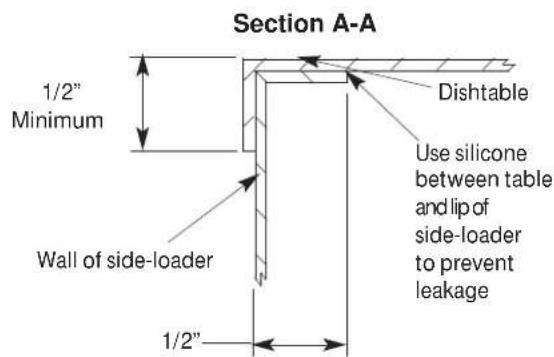
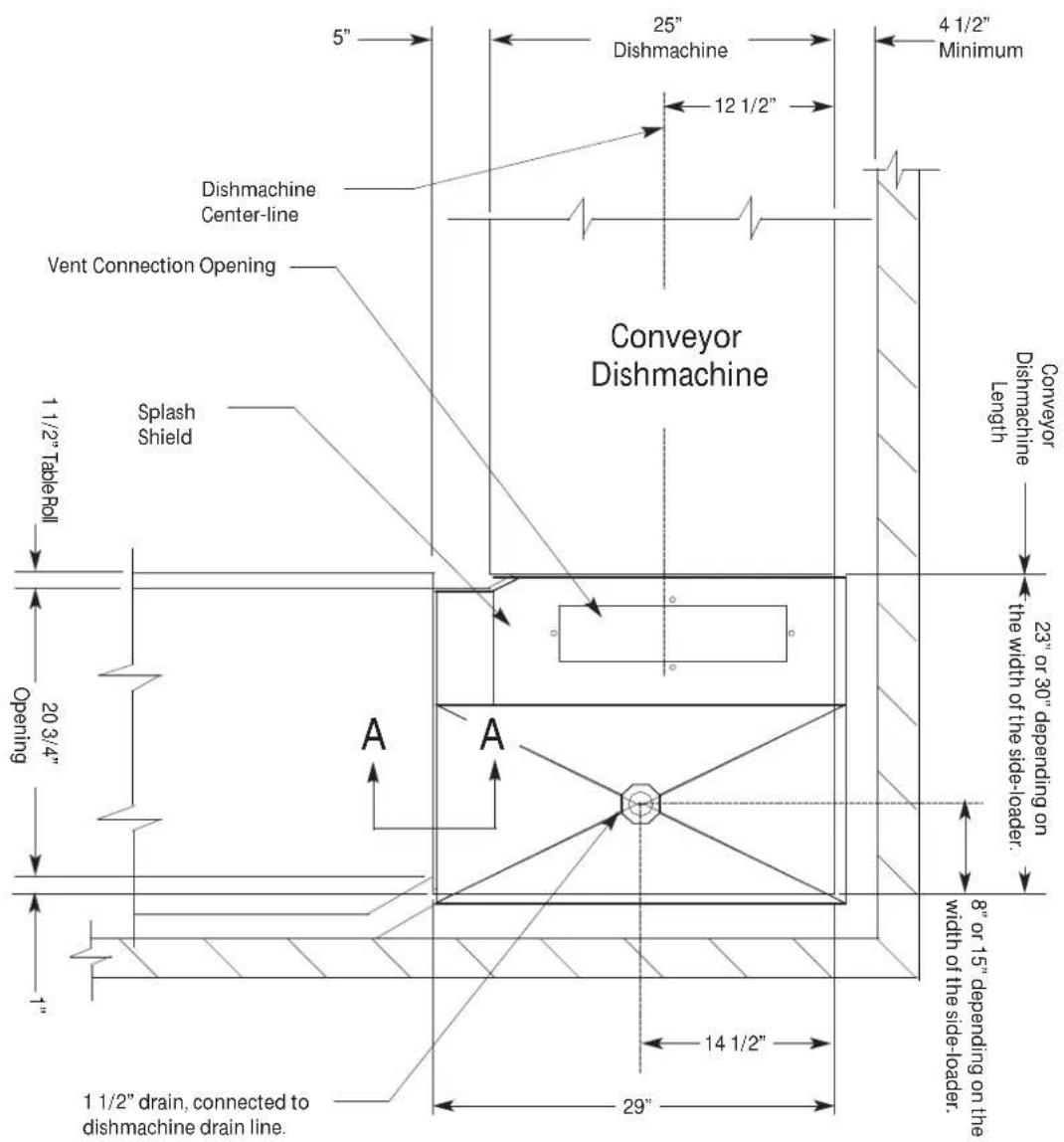
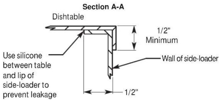
SIDE-LOADER RIGHT-TO-LEFT
SPECIFICATIONS
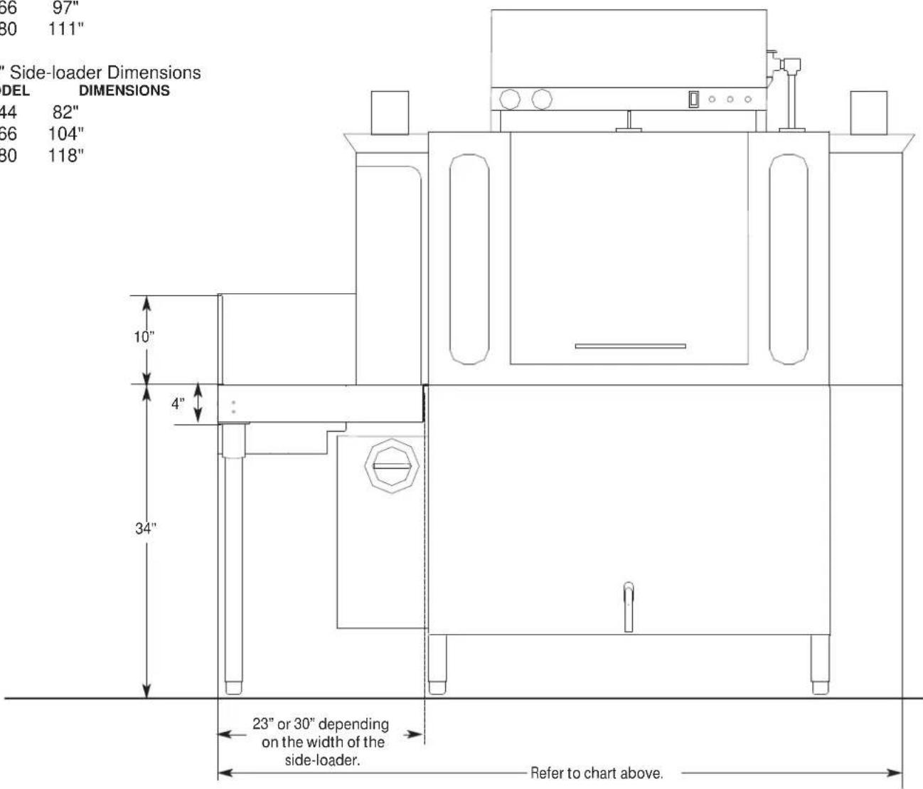
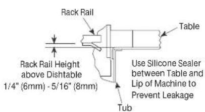
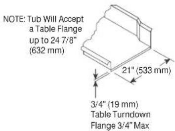
SIDE-LOADER & TABLE INSTALL
SIDE-LOADER
23" Side-loader Dimensions
MODEL DIMENSIONS
C-44 75"
C-66 97"
C-80 111"
30" Side-loader Dimensions
MODEL DIMENSIONS
C-44 82"
C-66 104"
C-80 118"
(Left-to-Right installation shown.)
TABLE
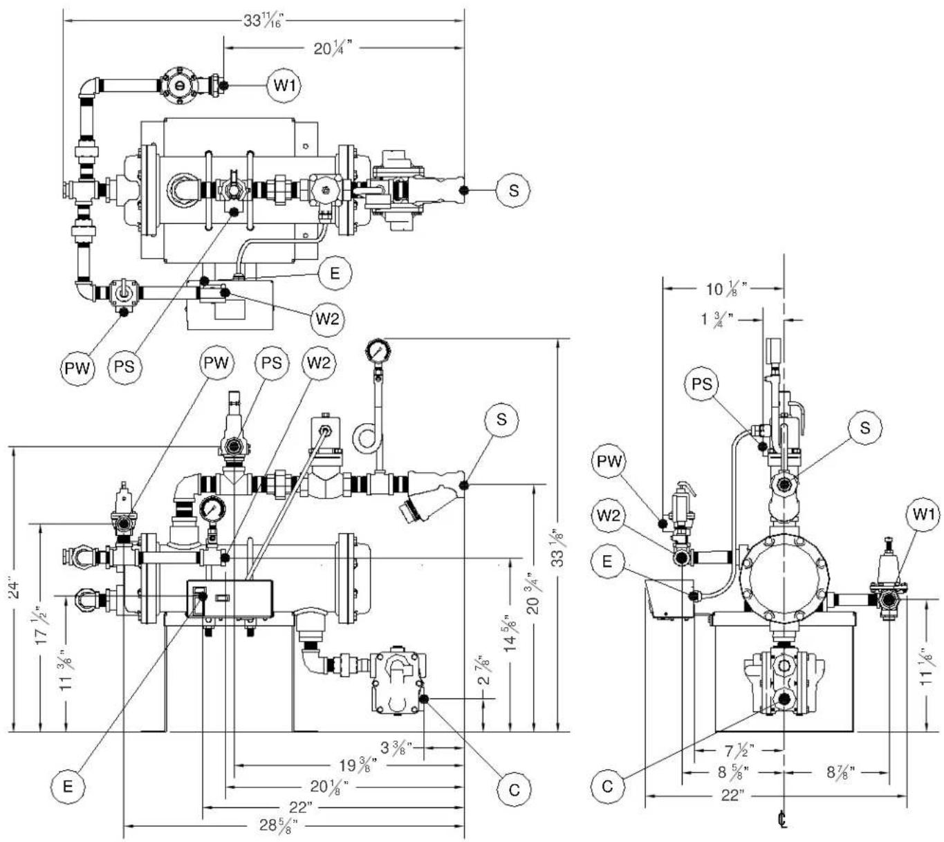
| E Main Electrical Connection (7/8" Hole) |
| W1 Main Inlet Water Connection (3/4" NPT) |
| W2 Water Outlet Connection (3/4" NPT) |
| PW Water Pressure Relief Outlet (3/4" NPT) |
| PS Steam | Pressure Relief Outlet (1" NPT) |
| S Steam Supply to Booster (1" NPT) | |
| C Steam Condensate Connection (3/4" NPT) | |
NOTICE For best performance, the steam booster should be installed no more than 20 feet from the dishmachine.
SPECIFICATIONS
Tank Capacity (Gallons) 17.25
Pump Capacity, C-66/76 (GPM) 120
Pump Capacity, C-80/90 (GPM) 270
Wash
Tank Capacity (Gallons) 20.4
Pump Capacity, All Models (GPM) 270
Ventilation Requirements (CFM)
Input End 200
Output End 400
Total 600
Steam Requirements
Steam Connection (NPT) 3/4"
Steam Flow Pressure (PSI) 10-30
Consumption at 15 PSI (lbs/hr) 60
Conveyor Speed (FPM)
High-temp 6.2
Low-temp 5.75
Gallons per Rack
High-temp 0.68
Low-temp 0.78
Motor Characteristics
Drive Motor (HP) 1/4
Wash Motor (HP) 2
Pre-wash Motor, C-66/76 (HP) 1
Pre-wash Motor, C-80/90 (HP) 2
WATER REQUIREMENTS
High-temp
Minimum Wash Temperature (°F/°C) 160/71
Minimum Rinse Temperature (°F/°C) 180/82
Pre-wash Temperature (°F/°C) 110-140/43-60
Flow Pressure (PSI) 15
Flow Rate (GPM) 2.57
Water Line Size (NPT) 1/2"
Drain Line Size (NPT) 1 1/2"
Low-temp
Minimum Wash Temperature (°F/°C) 140/60
Minimum Rinse Temperature (°F/°C) 140/60
Pre-wash Temperature (°F/°C) 110-140/43-60
Flow Pressure (PSI) 15
Flow Rate (GPM) 2.74
Water Line Size (NPT) 1/2"
Drain Line Size (NPT) 1 1/2"
Minimum Chlorine Required (PPM) 50


Always refer to the machine data plate for specific electrical and water requirements. The material provided on this page is for reference only and is subject to change without notice.

All electrical ratings provided in this manual are for reference only. Always refer to the machine data plate to get the exact electrical information for this machine. All electrical work performed on machines should be done in accordance with applicable local, state, territorial, and national codes. Work should only be performed by qualified electricians and authorized service agents. A list of authorized Service Agencies is located in the back of this manual.
Note that all electrical wiring used in the dishmachine must be rated, at a minimum, for 212 °F (100 °C), and that only copper conductors must be used.
Where applicable, heating element amperage draws have been adjusted for the assumed input voltage. The manufacturer assumes incoming voltages will be either 208, 230, or 460 Volts. Some of the heating elements used in our machines are actually rated for other voltages, such as 240 or 480 Volts. Always verify the amperage draw of the machine in operation when sizing circuit protection.
If the machine is equipped with the optional rinse heater, note the rinse heater has its own electrical connection and therefore requires a separate service. Amperage loads for motors and heaters are called out on the machine data plate for the installation/service technician.
The electrical configurations of the machines are as follows:
Available Electrical Characteristics:
• 208 V, 60 Hz, Single-phase
• 230 V, 60 Hz, Single-phase
• 208 V, 60 Hz, Three-phase
• 230 V, 60 Hz, Three-phase
• 460 V, 60 Hz, Three-phase
Available Wash Tank Heaters:
• 15 kW
• 18 kW
Available Booster Tank Heaters:
- None (standard)
• 12 kW (40 °F rise in temperature)
• 18 kW (70 °F rise in temperature)
• 27 kW

| C-44/54CE | with 15 kW Wash Heater with 18 kW Wash Heater | |||||
| Volts Phase | Hz Amps | Circuit (Amps) | Amps | Circuit (Amps) | ||
| 208 1 60 8 | 2.4 125 96.8 125 | |||||
| 230 1 60 7 | 5.5 100 88.6 125 | |||||
| 208 3 60 4 | 8.4 60 56.7 80 | |||||
| 230 3 60 4 | 4.4 60 51.9 70 | |||||
| 380 3 50 2 | 8.5 40 33.0 50 | |||||
| 460 3 60 2 | 2.3 30 26.0 35 | |||||
| C-44/54CS | with 15 kW Wash Heater with 18 kW Wash Heater | |||||
| Volts Phase | Hz Amps | Circuit (Amps) | Amps | Circuit (Amps) | ||
| 208 1 60 1 | 0.3 15 10.3 15 | |||||
| 230 1 60 1 | 0.3 15 10.3 15 | |||||
| 208 3 60 6 | 7 15 6.7 15 | |||||
| 230 3 60 6 | 7 15 6.7 15 | |||||
| 460 3 60 3 | 4 15 3.4 15 | |||||

| C-66/76CE | with 15 kW Wash Heater with 18 kW Wash Heater | |||||
| Volts Phase | Hz Amps | Circuit (Amps) | Amps | Circuit (Amps) | ||
| 208 1 60 8 | 8.4 125 102.8 150 | |||||
| 230 1 60 8 | 1.5 125 94.6 125 | |||||
| 208 3 60 5 | 1.8 70 60.1 80 | |||||
| 230 3 60 4 | 7.8 60 55.3 70 | |||||
| 460 3 60 2 | 4.0 30 27.7 35 | |||||
| C-66/76CS | with 15 kW Wash Heater with 13 kW Wash Heater | |||||
| Volts Phase | Hz Amps | Circuit (Amps) | Amps | Circuit (Amps) | ||
| 208 1 60 1 | 6.3 25 16.3 25 | |||||
| 230 1 60 1 | 6.3 25 16.3 25 | |||||
| 208 3 60 1 | 0.1 15 10.1 15 | |||||
| 230 3 60 1 | 0.1 15 10.1 15 | |||||
| 460 3 60 5.1 | 15 5.1 15 | |||||

| C-80/90CE | with 15 kW Wash Heater with 18 kW Wash Heater | |||||
| Volts Phase | Hz Amps | Circuit (Amps) | Amps | Circuit (Amps) | ||
| 208 1 60 9 | 0.9 125 105.3 150 | |||||
| 230 1 60 8 | 4.0 125 97.1 125 | |||||
| 208 3 60 5 | 4.0 70 62.3 80 | |||||
| 230 3 60 5 | 0.0 70 57.5 80 | |||||
| 460 3 60 2 | 5.0 30 28.8 40 | |||||
| C-80/90CS | with 15 kW Wash Heater with 18 kW Wash Heater | |||||
| Volts Phase | Hz Amps | Circuit (Amps) | Amps | Circuit (Amps) | ||
| 208 1 60 1 | 8.8 25 18.8 25 | |||||
| 230 1 60 1 | 8.8 25 18.8 25 | |||||
| 208 3 60 1 | 2.3 20 12.3 20 | |||||
| 230 3 60 1 | 2.3 20 12.3 20 | |||||
| 460 3 60 6 | 2 | 15 6.2 15 | ||||
| INSTALLATION | INSTRUCTIONS |
| INSPECTION | Before installing the unit, check the packaging and the machine for damage. Damaged packaging might be an indication there is possible damage to the product. If there is any type of damage to both the packaging and the unit, DO NOT THROW AWAY THE PACKAGING. The dishmachine has been previously inspected at the factory and is expected to arrive in new, undamaged condition. However, rough handling by carriers or others might result in damage to the unit while it is in transit. If this occurs, DO NOT RETURN THE UNIT TO THE MANUFACTURER. Instead, contact the carrier and ask them to send a representative to the site to inspect the damage and request that an inspection report be completed. Contact the carrier and dealer that sold you the unit within 48 hours of receiving the machine in order to report possible freight damage. |
| Do not throw away the packaging if damage is evident! | |
| UNPACKING | The machine should be unpacked and removed from the pallet before installing. Open the front door and remove all materials from inside. Once unpacked, verify there are no missing parts. If a part is missing, contact the manufacturer immediately. |
| LEVELING | The dishmachine is designed to operate while level. This is important to prevent any damage to the machine during operation and to ensure the best possible results. The unit comes equipped with adjustable bullet feet, which can be turned using a pair of pliers. Verify the unit is level from front-to-back and side-to-side before making any electrical or plumbing connections. |
| PLUMBING | All plumbing connections must be made to adhere to local, state, territorial, and national codes. The installing plumber is responsible for ensuring the incoming water lines are flushed of debris before connecting to the machine. Note that chips and materials from cutting processes can become lodged in the solenoid valves and prevent them from opening or closing. Any valves that are found to be fouled or defective because of foreign matter left in the water line and any subsequent water damage are not the responsibility of the manufacturer. |
| The plumber MUST flush the incoming water line! | Water hardness should be a maximum of 6 GPG. Hard water should be treated before being used by the machine. Iron in the water line can cause staining. A filter designed to remove iron from the water supply is highly recommended for supplies in excess of 0.1 ppm.The manufacturer has an optional water pressure regulator (see Miscellaneous Parts section) to accommodate areas where water pressure fluctuates or is higher than the recommended pressure. The unit utilizes a flow pressure of 15 PSI for the incoming water line. Do not confuse static pressure with flow pressure. Static pressure occurs when there is no flow and the valves are closed. Flow pressure occurs when water is running into the machine. The pressure regulator should be adjusted to the proper flow pressure indicated on the data plate. |
 | The water supply line must be 1/2" NPT minimum and must be able to provide water at the minimum temperature indicated on the machine data plate.A shut-off valve should be installed to allow isolating the dishmachine from the water system in the event service is required. The optional shock absorber (see Miscellaneous Parts section) should also be installed on the incoming water line. This prevents water hammer (hydraulic shock)—induced by the solenoid valve as it operates—from causing damage to the equipment. |
INSTALLATION
INSTRUCTIONS
DRAIN LINE
The drain for the unit is a gravity-discharge drain. All piping to the machine drain must be a minimum 1 1/2" NPT and must not be reduced. There must also be an air-gap between the machine drain line and the floor sink or drain. If a grease trap is required by code, it should have a flow capacity of 30 GPM. C-44/54 units have one drain connection point and C-66/76/80/90 units have two.
STEAM LINE CONNECTIONS

Some machines covered in this manual are designed to use low-pressure steam as a source of heat for the wash tank. Those machines come with lines by which an outside source of steam (e.g. steam booster) is connected. Connect all steam lines from the booster to the machine in accordance with the booster manufacturer's instructions. Ensure that all applicable codes and regulations are adhered to. See the machine data plate for information related to steam flow requirements.
PLUMBING CHECK
Slowly turn on the water supply to the machine after the incoming fill line and drain line have been installed. Check for any leaks and repair as required. All leaks must be repaired before placing the machine in operation.
ELECTRICAL POWER CONNECTIONS


Disconnect electrical power at the breaker or disconnect switch and tag-out in accordance with procedures and codes.
All electrical connections are to be made in accordance with applicable portions of local, state, territorial, and national codes.
This manual provides reference information regarding electrical requirements and loads, but that information may change without notice. Always refer to the machine data plate for voltage requirements, machine voltage, total amperage load, and serial number. If a data plate has been damaged and cannot be read, contact the manufacturer. The data plate is located on the right side and to the front of the machine.
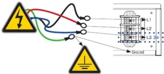
To install the incoming power lines, open the control box. Install conduit into the pre-punched holes in the back of the control box. Route power wires and connect to power block and grounding lug. Install the service wires (L1, L2, and L3 (L3 for 3-phase only)) to the appropriate terminals as they are marked on the terminal block. Install the grounding wire into the lug provided. Tighten the connections. It is recommended that "DE-OX" or another similar anti-oxidation agent be used on all power connections. Verify the incoming voltage matches the voltage indicated on the decal next to the incoming power pre-punched hole.
NOTICE
Imbalanced wild leg goes to L3.

NOTICE The dishmachine has a separate power connection from the rinse booster heater and the circuit protection requirements are different for each. Refer to the machine data plate for information on minimum circuit protection.
CAUTION! Improperly connecting external devices can cause damage to the machine and/or electrical infrastructure!
INSTALLATION
INSTRUCTIONS
VENTILATION
The dishmachine should be located with an adequate exhaust hood or ventilation system with provisions for venting. This is essential to permit efficient removal of the condensation exhaust. Ensure the exhaust system is acceptable in accordance with applicable codes and standards.
NOTICE Any damage that is caused by steam and/or moisture due to improper ventilation is NOT covered under the warranty.
Dishmachine ventilation requirements:
- Load End: 200 CFM
- Unload End: 400 CFM
The exhaust system must be sized to handle this volume for the dishmachine to operate properly.
THERMOSTATS
The thermostats on this unit have been set at the factory and should only be adjusted by an authorized service agent.
CHEMICAL FEEDER EQUIPMENT

Contact the chemical supplier to discuss chemical concentrations, water hardness, third-party feeders, and operator training.
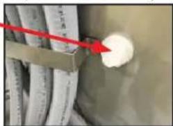
Detergent can be introduced into the unit by removing the bulkhead plug in the rear of the tub and replacing it with the third-party detergent injection fitting. Remove the bulkhead plug in the side of the tub to install the detergent concentration probe.
• Detergent Connection Point (back of machine)
natural_image
Close-up of a metallic pipe with white insulation and a red arrow pointing to a white spherical object, no visible text or symbols.- Rinse-aid and Sanitizer Connection Points (top of machine)
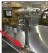
The 1/8" brass plugs on the incoming plumbing rinse injector can be removed to install rinse-aid and sanitizer injection fittings.
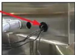
• Chemical Injector Wiring (back of control box)
natural_image
Close-up of a metallic mechanical component with wires and a red arrow pointing to a black circular component (no visible text or symbols)All wires for the chemical injectors should be routed through one of the extra openings in the back of the control box.
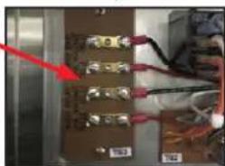
• Terminal Wiring (inside of control box)
natural_image
Close-up of electronic circuit board with wires and connectors (no visible text or symbols)Terminals marked "CVS" provide a voltage signal when the drive motor is operating.
Terminals marked "DET" provide a voltage signal when the wash motor is operating.
CURTAINS
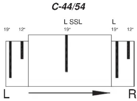
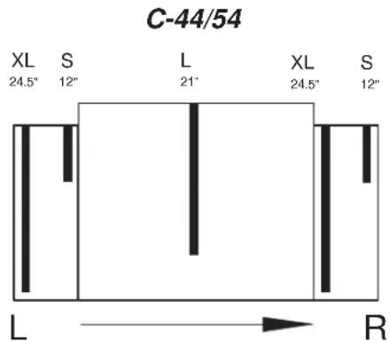
The unit has decals marking the curtain locations inside the machine, starting at the load end and ending at the unload end. The illustrations below indicate the size of the curtain to be placed on the curtain hooks provided. If any curtain components are missing, these must be obtained and installed before operation. See the Miscellaneous Parts section for part numbers.
DETERMINING CONVEYER DIRECTION: The dishmachine will be configured for either Left-to-Right or Right-to-Left operation. Direction is from the load end to the unload end, as shown below. Left-to-Right is shown, Right-to-Left is mirrored.
Low Hood Machines
High Hood Machines
C-66/76/80/90
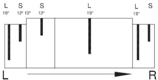
C-66/76/80/90
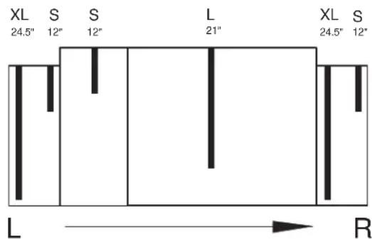
IMPORTANCE OF PROPER CURTAIN PLACEMENT: The curtains inside the dishmachine must be installed properly for the machine to operate correctly. Curtains are used to control air currents inside the unit and assist in maintaining the heat necessary to keep energy costs down. Note the approximate locations for each type of curtain in the above illustrations. S = Short, L = Long, and XL = Extra Long. See the Miscellaneous Parts section for part numbers.
PREPARATION
Before operating the unit, verify the following:
- The drain handle is turned to "CLOSED."
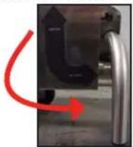
natural_image
Close-up of a mechanical component with a red curved arrow indicating rotation or movement (no text or symbols visible)- The strainers and pawl bar are installed and secure.
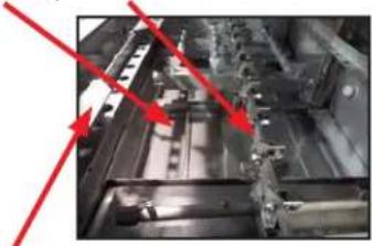
natural_image
Industrial machinery interior with red arrows pointing to structural components (no visible text or symbols)-
The actuator switches move with relative freedom and do not bind.
-
The curtains are installed correctly.
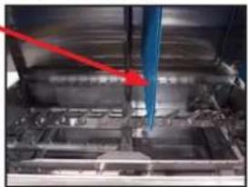
natural_image
Close-up of a mechanical assembly with a red arrow pointing to a blue component (no visible text or symbols)POWER UP
- Turn the power on at the service breaker.
For machines with pre-wash sections, ensure water is present in the pre-wash section before operating.
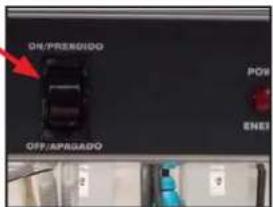
- Press the "ON" button on the front of the machine to fill the machine and heat the water.

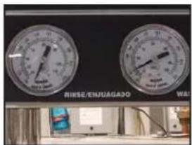
- Allow wash tub to fill completely and wash water to reach operating temperature before continuing. (An accurate rinse temperature will not display until unit is rinsing.)
- For Steam machines, ensure the steam service is connected and steam is flowing to the machine.
OPERATION
OPERATING INSTRUCTIONS
FIRST RACK
The first rack of ware that is placed in the unit will typically reduce the temperature of the wash tank, and the first rack might need to run through the unit again. This process might be necessary any time the unit has not been operated for an extended period of time, although this is dependent on the type of ware being used, its temperature, and the ambient temperature of the kitchen area. To ensure proper operation, always observe the temperatures of the wash and rinse when first starting the unit.
WARE PREPARATION
Proper preparation of ware is essential for the smooth, efficient operation of this dishmachine.
Any ware placed in the unit should have all solid food waste and scraps removed. Ware should also be sprayed-down before entering the dishmachine.
Place cups and glasses upside-down in racks so they do not hold water during the cycle. Presoak flatware in warm water to assist in removing food. Load plates and saucers in the same direction, with the food surface facing the unload end of the machine.
WASHING A RACK OF WARE
This dishmachine is designed to wash ware that is placed in a rack. Materials should not be placed in the machine unless they are properly secured in a dish rack.
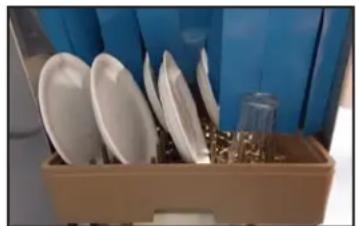
To start the cycle, gently push the rack into the unit on the load end. Once the wash actuator has moved sufficiently, the unit will automatically begin to convey the dish rack through the unit. The entire cycle is automatic.
natural_image
Interior view of a toolbox containing various kitchen utensils and plastic components (no visible text or labels)OPERATIONAL INSPECTION

For machines with pre-wash sections, also inspect the pre-wash strainer and wash arm nozzles.
Operators should periodically review the following items while the machine is operating. These items are important for operating the machine in an efficient manner.
- Review wash and rinse temperatures and compare to the minimums on the data plate.
- Verify the strainers are not becoming clogged. Keeping these free of soil and debris allows for much better flow of water through the machine and prevents any sort of redeposit issues.
- Water pressure: The dishmachine is designed to run at 15 PSI; if it is any lower there will not be enough rinse water to properly remove detergent from the ware.
- Wash and rinse arm nozzles should be free of debris. Open nozzles are essential to the operation of the dishmachine.
OPERATION
OPERATING INSTRUCTIONS
SHUTDOWN
To shut the unit down, press the "OFF" button on the front of the machine. To drain the machine, move the drain handle to the "OPEN" position. If the machine is equipped with a steam booster, shut it down in accordance with its manufacturer's instructions.
CLEANING
Clean the unit at least once every 24 hours or at the end of the day. Cleaning assists in maintaining the efficient operation of the unit by removing soil and debris that might otherwise become trapped in nozzles or deposited onto ware.
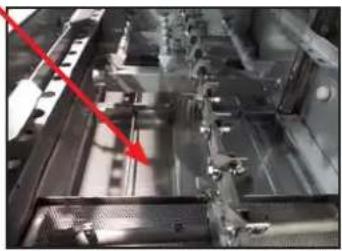
- Remove all strainers and use a hand-scraper to scrape foodsoil into trash.
For machines with pre-wash sections, also remove and clean the pre-wash strainer.
natural_image
Industrial machinery component with metal beams and a red arrow pointing to a specific part (no visible text or symbols)- Remove the float switch cover and clean it and strainers with the pre-rinse hose.
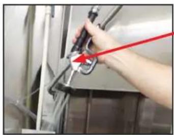
natural_image
Person using a tool on a stainless steel appliance (no visible text or symbols)- Rinse the float switch off and rinse the tank out; inspect tank for debris.
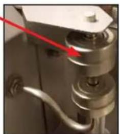
natural_image
Close-up of a metallic mechanical component with a red arrow pointing to a cylindrical assembly (no visible text or symbols)- Remove curtains, scrub with mild detergent and brush, and allow to air-dry.
For machines with pre-wash sections, also remove and clean the pre-wash curtains.
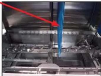
natural_image
Industrial machinery interior with blue pipes and metal components, no visible text or symbolsOPERATION
OPERATING INSTRUCTIONS
CLEANING
- As needed, clean the wash and rinse arms:
a. Remove the wash arm manifolds.
For machines with pre-wash sections, also remove and clean the pre-wash arm.
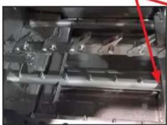
natural_image
Close-up of a metallic mechanical component with visible grooves and bolts, no text or symbols present.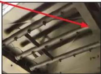
natural_image
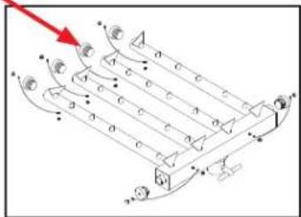
Close-up of metallic cylindrical components with a red arrow pointing to them (no visible text or symbols)b. Remove the end-caps from the arms and manifolds.
flowchart
graph TD
    A["Top Node"] --> B["Left Column"]
    B --> C["Center Point"]
    C --> D["Right Column"]
    D --> E["Bottom Column"]
    E --> F["Left Column"]
    style A fill:#f9f,stroke:#333
    style F fill:#bbf,stroke:#333
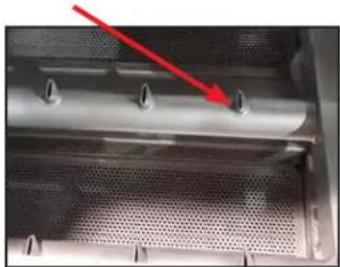
c. Clean nozzles with a brush. Also clean the rinse assembly nozzles.
natural_image
Close-up of a metallic cylindrical component with mounting holes and a red arrow pointing to a small hole (no text or symbols visible)
natural_image
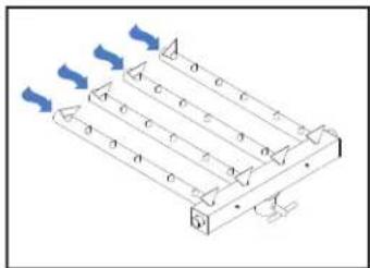
Close-up of a mechanical component with a red arrow pointing to a specific part (no visible text or symbols)d. Use a small wire or toothpick to remove remaining debris or lime deposits from the nozzles.
e. Flush the arms with water.
natural_image
Isometric diagram of a mechanical or electrical component with multiple parallel plates and blue directional arrows (no text or symbols)f. Replace end-caps and ensure they have been tightened.
g. Replace the wash arm manifolds.
Do NOT clean the unit with any type of metallic scrubbing sponge!
The outside of the unit should be cleaned with a standard countertop or general cleaner. Do not attempt to clean inside any compartments, boxes, or chambers that are secured with a cover. These normally contain live electrical components.
DELIMING
-
Disconnect/turn off chemical feeder equipment.
-
Turn machine on.
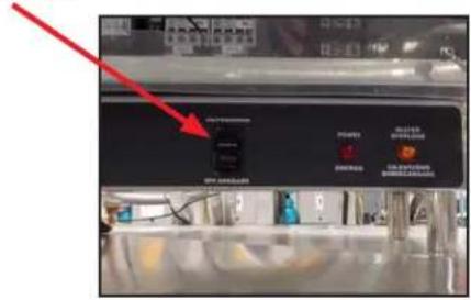
-
Add deliming solution per chemical supplier's instructions.
-
Close the door.
-
Flip the AUTOMATIC/DELIME switch to DELIME.
-
Run machine the period of time recommended by chemical supplier.
-
Wait five minutes, then inspect the inside of the machine. If the machine is not delimited, run again.
-
Flip the AUTOMATIC/DELIME switch to AUTOMATIC.
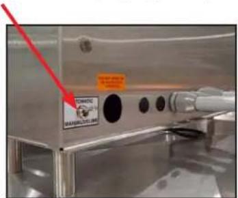
-
Run an empty rack through the machine twice.
-
Drain and re-fill the machine.
-
Reconnect/turn on chemical feeder equipment.

CAUTION! This equipment is not recommended for use with deionized water or other aggressive fluids. Use of deionized water or other aggressive fluids will result in corrosion and failure of materials and components. Use of deionized water or other aggressive fluids will void the manufacturer's warranty.
MAINTENANCE
PREVENTATIVE MAINTENANCE
PREVENTATIVE MAINTENANCE
The manufacturer highly recommends that any maintenance and repairs not specifically discussed in this manual be performed only by QUALIFIED SERVICE PERSONNEL. Performing maintenance on your dishmachine may void your warranty, lead to larger problems, or even cause harm to the operator. So if you have a question or concern, do not hesitate to contact a QUALIFIED SERVICE AGENCY.
By following the operating and cleaning instructions in this manual, you should get the most efficient results from your machine. As a reminder, here are some steps to ensure the dishmachine is being used the way it was designed to work:

- Ensure that the water temperatures match those listed on the machine data plate. There can be a variety of reasons why the water temperature could be too low.
- Ensure that all strainers are clean and in place laying flat before operating the machine. When cleaning out strainers, do NOT beat them on waste cans. Wipe-out strainers with a rag and rinse under a faucet if necessary. Use a toothpick to dislodge any stubborn debris.
- Ensure that all wash and rinse arms are secure in the machine before operating.
- Ensure that drains are closed before operating.
- Remove as much soil from dishes by hand as possible before loading into racks.
- Do not overfill racks.
- Ensure that glasses are placed upside-down in the rack.
- Ensure that all chemicals being injected into machine have been verified at the correct concentrations.
- Clean the unit every 24 hours or at the end of every workday per the instructions in this manual.
- Follow all safety procedures, whether listed in this manual or put forth by local, state, or national codes/regulations.
TORQUE SETTINGS
When replacing components in the control box or heater box, refer to the table below for the torque specs:
| ITEM TORQUE SPEC | |
| Relays 16 in/lbs | |
| Heater Contactor 35 in/ls | |
| Heater Nuts 16 in/lbs | |
| Terminal Block | 50 in/lbs |
DRIVE GEAR REDUCER LUBRICATION
The maintenance procedures detailed here are manufacturer's instructions for the brand of gear reducer that is installed on the machines covered in this manual.
| Ambient Temperature -30 | to 15°F 16 to 50°F 51 | to 95°F 51 to 95°F 96 to 131°F 96 to 131°F | |||
| Final Stage Worm Speed* | up to 2000 FPM | up to 2000 FPM | up to 450 FPM | above 450 FPM | up to 450 FPM |
| ISO Viscosity Grade | 220 | 460 | 680 | 460 | 680 |
| AGMA Lubricant No. | 5S** | #7 Compounded*** | #8 Compounded*** | #7 Compounded*** | 8 S** |
| Mobil | SHC 630 | 600W Super Cylinder | Extra Hecla Super | 600W Super Cylinder | SHC 636 | SHC 634 |
| American Lubricants | SHC-90W | AGMA #7 Gear Oil | AGMA #8 Gear Oil | AGMA #7 Gear Oil | N/A | N/A |
| Castrol | Tribol 800/220 | Tribol 1105-7C | Tribol 1105-8C | Tribol 1105-7C | Tribol 800/680 | Tribol 800/460 |
| Chevron | Tegra 220 | Cylinder Oil W460 | Cylinder Oil W680 | Cylinder Oil W460 | Tregra 680 | Tegra 460 |
| Conoco | Syncon R & O 220 | Inca Oil 460 | Inca Oil 680 | Inca Oil 460 | N/A | Syncon R & O 460 |
| Exxon (Esso) | Teresstic SHP 220 | Spartan EP 460 | Spartan EP 680 | Spartan EP 460 | Teresstic SHP 680 | Teresstic SHP 460 |
| Fiske Brothers | SPO-MG | SPO-277 | SPO-288 | SPO-277 | N/A | N/A |
| Shell | Omala RL 220 | Valvata J 460 | Valvata J 680 | Valvata J 460 | Omala RL 680 | Omala RL 460 |
| Texaco | Pinnacle 220 | Vanguard 460 | Vanguard 680 | Vanguard 460 | Pinnacle 680 | Pinnacle 460 |
*The sliding velocity in feet per minute (FPM) for standard ratios is determined by multiplying the speed of the worm in RPM by the factor from the following table. For selecting the proper lubricant, use the speed of the worm in the final stage (input RPM divided by the first stage ratio).
**Synthetic oil.
***3% to 10% fatty or synthetic oils or mild EP additives.
Lubricant selections are provided by the lubricant manufacturer based on AGMA recommended viscosity grades.
Viscosity grades are based on Lubrication Standard ANSI/AGMA 9005-D94.
Nominal Ratio
Factory filling - Speed reducers are filled with oil at the factory to the proper level for the standard mounting position it will be found on the unit. The oil level should be checked and adjusted (if necessary) before operation, using the oil level plug provided and while the unit is oriented in its operating position.
Ambient temperature - If the operating ambient temperature is other than 51 - 95°F, refer to the lubrication chart and refill the unit with the correct grade based on actual ambient temperature and operating speed. See “Oil changing” below for additional information.
Oil changing - When changing the oil for any reason, it should be remembered that oils of various types might not be compatible. Therefore, when changing to a different oil, it is recommended that the housing be completely drained and thoroughly flushed with a light flushing oil before refilling with the appropriate lubricant. The oil level should be rechecked
DRIVE GEAR REDUCER LUBRICATION
after a short period of operation and adjusted, if necessary. When changing double-reduction models, each housing should be drained and filled independently, even though there could be a common level.
Initial oil change - The new oil in a speed reducer should be changed at the end of 250 hours of operation. This is equivalent to 30 days of operation for eight hours per day; 15 days of operation for 16 hours per day, or 10 days of operation for 24 hours per day.
Subsequent oil changes - Under normal conditions, after the initial oil change, the oil should be changed after every 2500 hours of operation, or every six months, whichever comes first. Under severe conditions (rapid temperature changes, moist, dirty, or corrosive environment) it could be necessary to change the oil at intervals of one to three months. Periodic examination of oil samples taken from the unit will help establish the appropriate interval.
Synthetic oils - Synthetic lubricants can be advantageous over mineral oils in that they generally are more stable, have a much longer life, and operate over a wider temperature range. These oils are appropriate for any application but are especially useful when units are subjected to low start-up temperatures or high operating temperatures. However, continuous operation above 225°F may cause damage to seals or other components. It is recommended that the initial oil be changed or filtered after the first 1500 hours of operation to remove metal particles that accumulate during break-in. Subsequent oil changes should be made after 5000 hours operation if units are operating in a clean environment. This can be extended to 10,000 hours if using new reformulated Mobil SHC lubricants (orange in color) and the lubricant remains free of contamination over this period. See comments under “Subsequent oil changes” for discussion of severe ambient conditions.
Long-term storage or infrequent operation - If a speed reducer is to stand idle for an extended period of time, either before installation or during use, it is recommended that the unit be filled completely with oil to protect interior parts from rust and corrosion due to internal condensation. Be sure to drain the oil to the proper level before placing the speed reducer in service.
Grease fittings - Some units are equipped with grease fittings to lubricate bearings not adequately lubricated by the oil splash. These fittings must be lubricated every three to six months depending on operating conditions. Bearing greases must be compatible with the type of gear lubricant being used (e.g. mineral, synthetic, food grade, etc.). For mineral oils, use a high-quality lithium base NLGOI #2 bearing grease. For synthetic oils, use a synthetic bearing grease such as Mobil Synthetic Universal grease, Mobilith SHC 100 or a suitable equivalent. For food-grade lubricants, use Chevron FM grease, NGLI 2, or equivalent.
Low input speeds (under 1600 RPM) - When input speeds are less than 1600 RPM, grease fittings will be required to lubricate any bearings not partially covered by the normal oil level.
Oil temperature - Speed reducers in normal operation can generate temperatures up to 200^ F depending on the type of reducer and the severity of the application (loading, duration of service, ambient temperatures). Excessive oil temperatures could be the result of several factors including overloading, overfilling, underfilling, or inadequate cooling.


WARNING: Inspection, testing, and repair of electrical equipment should only be performed by a qualified service technician. Many of the tests require that the unit have power to it and live electrical components be exposed. USE EXTREME CAUTION WHEN TESTING THE MACHINE.
| PROBLEM POSSIBLE CAUSE REMEDY | ||
| Nothing on machine operates. The power switch is ON and the power indicator light is OFF. | 1. Machine is not wired correctly to incoming power source.2. Machine circuit breaker is tripped.3. Service breaker is tripped. | 1. Have an electrician verify wiring.2. Reset the circuit breaker. If it trips again, contact an electrician to verify the machine amp draw.3. Reset the service breaker. If it trips again, contact an electrician to verify the machine amp draw. |
| Machine will not fill. The power switch is ON and the power indicator light is ON. | 1. No water supplied to machine.2. Dishmachine doors are not closed.3. Incoming water solenoid valve damaged/faulty.4. Tank floats faulty. | 1. Verify that water lines have been connected to the machine.2. Close doors completely.3. Verify that the valve is operating. If not, replace.4. Verify the wiring of the floats. Verify that no debris is jamming the floats. Replace if necessary. |
| Machine fills, but fill is weak. | 1. Low incoming water pressure.2. Incoming water solenoid is clogged. | 1. Verify that incoming water pressure during fill is 15 PSI.2. Verify that debris is not trapped in valve. If so, remove debris. |
| Low wash tank temperature. | 1. Low incoming water temperature.2. Heater not energizing.3. Low incoming voltage. | 1. Verify that the incoming water temperature matches the data plate.2. Verify that the wash tank heater is operating. If not, replace.3. Have an electrician verify that incoming power is the same as indicated on the data plate. |
| Low wash arm pressure, poor spray pattern. | 1. Clogged wash arm nozzles.2. Clogged wash tank or wash pump strainers.3. Worn wash pump impeller. | 1. Verify that nozzles are not clogged with debris. If so, remove debris.2. Clean out strainers if necessary.3. Verify status of impeller and replace if necessary. |
| Inadequate rinse. | 1. Low incoming water pressure.2. Incoming water solenoid is clogged. | 1. Verify that incoming water pressure during fill is 15 PSI.2. Verify that debris is not trapped in valve. If so, remove debris. |
| Pawl bar moves with no load, but does not move when loaded. | 1. Clutch on drive assembly is out of adjustment. | 1. Adjust as required. |


WARNING: Inspection, testing, and repair of electrical equipment should only be performed by a qualified service technician. Many of the tests require that the unit have power to it and live electrical components be exposed. USE EXTREME CAUTION WHEN TESTING THE MACHINE.
| PROBLEM POSSIBLE CAUSE REMEDY | ||
| Pawl bar does not move. | 1. Failed or broken overload spring.2. No power to the drive motor or failed drive motor.3. Pawl bar not properly installed. | 1. Replace spring if necessary.2. Verify power and wiring connections to the motor. If necessary, replace the motor.3. Verify that the pawl bar is installed correctly. |
| Racks go through the machine, but results are poor. | 1. Incorrect quantity of detergent for the water volume.2. Clogged strainers/scrap basket.3. Ware not being properly pre-scrapped.4. Wash or rinse arms missing end-caps.5. Low tank heat.6. Inadequate rinse.7. Incorrect voltage coming to the machine.8. Wash pump cavitation due to low water level. | 1. Adjust detergent to appropriate level.2. Clean out strainers and scrap basket.3. Review “Ware Preparation” section.4. Verify and replace as required.5. See previous page.6. See previous page.7. Verify that the voltage matches that on the machine data plate.8. Verify that the drains are shut and that the water level is correct. |
| Spotting of silverware, glasses, and dishes. | 1. Incorrect final rinse temperature.2. Clogged wash and/or rinse nozzles and arms.3. Excessively hard water.4. Loss of water pressure due to clogged/obstructed wash pump.5. Ware not being properly pre-scrapped.6. Incorrect detergent/chemical concentrations. | 1. Verify that the rinse water temperature matches the data plate.2. Remove the arms and verify that they and their nozzles are free of debris.3. Install a water softener.4. Turn the power off to the machine at the source. Drain the wash tank of water and verify that the pump intake is free of debris.5. Review the “Ware Preparation” section.6. Verify that the detergent/chemical concentrations are correct for the associated water volume. |
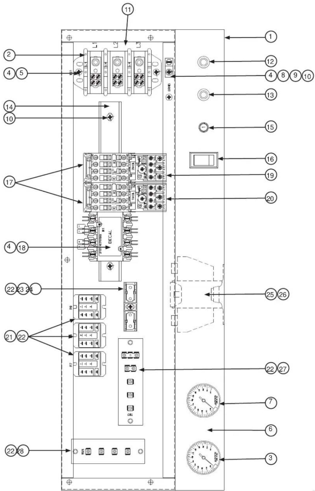
| ITEM QTY | DESCRIPTION | PART NUMBER | |
| 1 1 Electrical | Box 05700-041-88-43 | ||
| 2 1 Terminal | Block 05940-011-48-27 | ||
| 3 | 1 | Rinse Thermometer, 96" Lead | 06685-111-68-48 |
| 1 | Rinse Decal, 180 °F | 09905-002-97-62 | |
| 4 6 Star Washer, External Tooth, 10-24 05311-273-02-00 | |||
| 5 6 Screw, 10-32 x 3/4" Long Phillips Trusshead 05305-011-62-17 | |||
| 6 1 Decal, Gauge 09905-021-72-29 | |||
| 7 | 1 | Wash, Thermometer, 48" Lead | 06685-111-68-49 |
| 1 | Wash Decal, 160 °F | 09905-003-00-69 | |
| 8 1 Wire Lug, 2 AWG to 14 AWG 05940-200-76-00 | |||
| 9 1 Decal, Ground 09905-011-86-86 | |||
| 10 2 Screw, 10-32 x 1/2" Long Phillips Trusshead 05305-011-39-36 | |||
| 11 1 Decal, L1, L2, L3 | 09905-101-12-66 | ||
| 12 1 Light, Amber | 05945-111-44-44 | ||
| 13 1 Light, Red | 05945-111-44-45 | ||
| 14 1 Din Rail | 05700-021-72-75 | ||
| 15 1 Circuit Breaker (208-230 Volt, 60 Hz Models Only) | 05925-011-68-34 | ||
| 16 1 Switch, ON/FILL - OFF/DRAIN | 05930-301-46-00 | ||
| 17 2 Motor Contactor | 05945-111-68-38 | ||
| 18 1 Heater Contactor (Non-steam Units Only) | 05945-002-24-70 | ||
| 19 1 Overload | See "Motor Overloads" page. | ||
| 20 1 Overload | See "Motor Overloads" page. | ||
| 21 1 Control Relay 05945-111-35-19 | |||
| 22 2 Control Relay 05945-111-72-51 | |||
| 23 10 Screw, 6-32 x 3/8" Long Round Phillipshead | 05305-002-25-91 | ||
| 24 1 Fuse (460 Volt Models Only) | 05920-011-72-88 | ||
| 25 1 Fuse Holder (460 Volt Models Only) | 05920-011-72-89 | ||
| 26 1 Transformer | 05950-011-68-35 | ||
| 27 4 Locknut, 10-24 with Nylon Insert | 05310-373-01-00 | ||
| 28 1 Terminal Board | 05940-002-78-97 | ||
| 29 1 Terminal Board | 05940-021-89-41 | ||
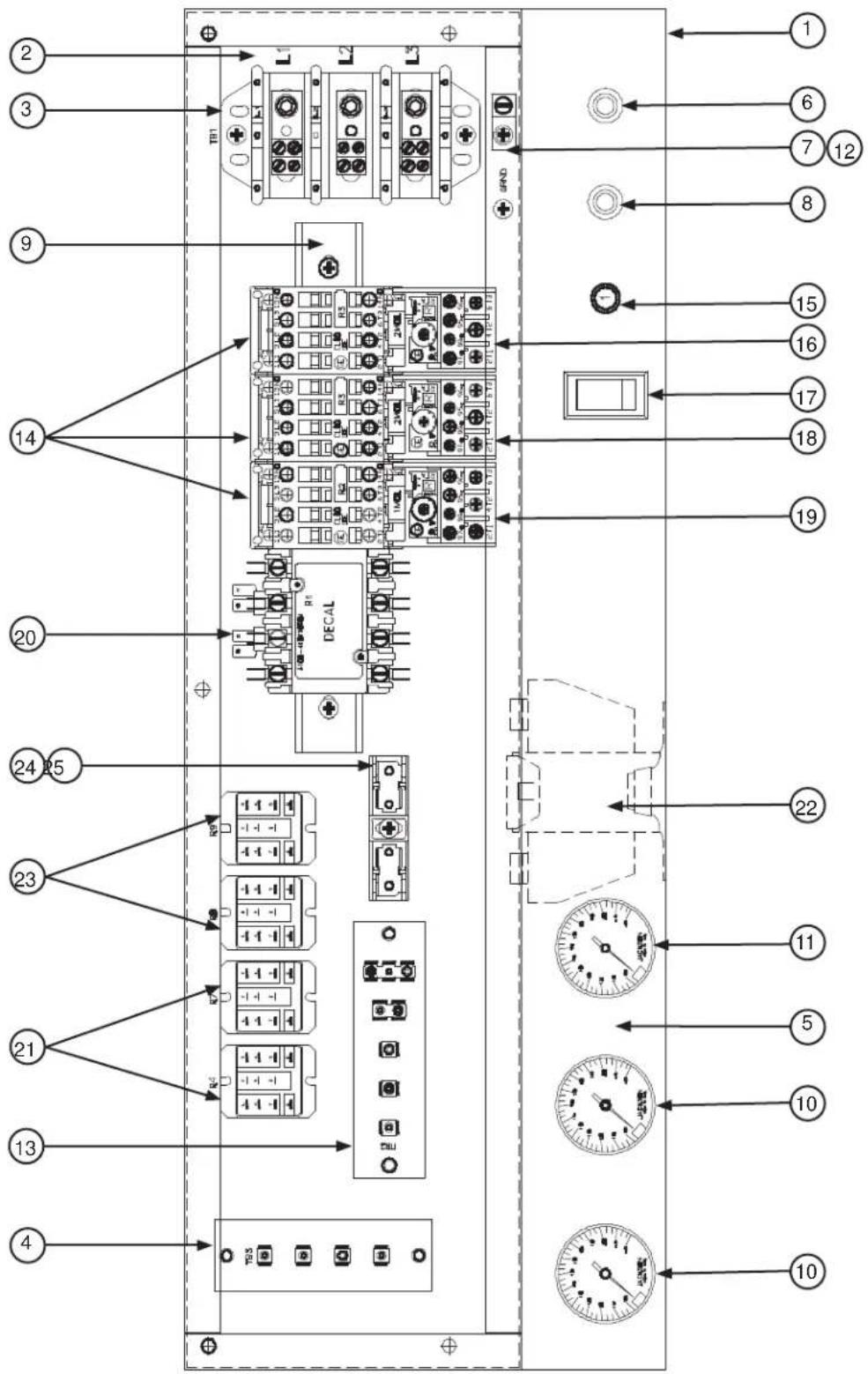
| ITEM QTY | DESCRIPTION | PART NUMBER | |
| 1 1 Electrical | Box 05700-041-88-50 | ||
| 2 1 Decal, L | 1, L2, L3 09905-101-12-66 | ||
| 3 1 Terminal | Block 05940-011-48-27 | ||
| 4 1 Terminal | Board 05940-021-89-41 | ||
| 5 1 Decal, Gauge | 09905-021-72-30 | ||
| 6 1 Light, Amber | 05945-111-44-44 | ||
| 7 1 Wire Lug, 2 AWG to | 14 AWG 05940-200-76-00 | ||
| 8 1 Light, Red | 05945-111-44-45 | ||
| 9 1 Din Rail | 05700-021-72-75 | ||
| 10 | 2 | Rinse Thermometer, 96" LeadRinse Decal, 180 °F | 06685-111-68-4809905-002-97-62 |
| 11 | 1 | Wash, Thermometer, 48" LeadWash Decal, 160 °F | 06685-111-68-4909905-003-00-69 |
| 12 | 1 Decal, Ground | 09905-011-86-86 | |
| 13 | 1 Terminal Board | 05940-002-78-97 | |
| 14 | 3 Motor Contactor | 05945-111-68-38 | |
| 15 | 1 | Circuit Breaker (208-230 Volt, 60 Hz Models Only) | 05925-011-68-34 |
| 16 | 1 Overload | See "Motor Overloads" page. | |
| 17 | 1 Switch, ON/FILL - OFF/DRAIN | 05930-301-46-00 | |
| 18 | 1 Overload | See "Motor Overloads" page. | |
| 19 | 1 Overload | See "Motor Overloads" page. | |
| 20 | 1 Heater Contactor (Non-steam Units Only) | 05700-002-24-70 | |
| 21 | 2 Control Relay | 05945-111-72-51 | |
| 22 | 1 Transformer | 05950-011-68-35 | |
| 23 | 2 Control Relay | 05945-111-35-19 | |
| 24 | 1 Fuse Holder (460 Volt Models Only) | 05920-011-72-89 | |
| 25 | 1 Fuse (460 Volt Models Only) | 05920-011-72-88 | |
C-44/54
| VOLTS | Hz PHASE DRIVE MOTOR PRE-WASH MOTOR WASH MOTOR | ||||
| 208 50 3 | 05945-011-84-59 | N/A 05945-111 | 1-68-40 | ||
| 220 50 3 | 05945-011-84-59 | N/A 05945-111 | 1-68-40 | ||
| 230 50 3 | 05945-011-84-59 | N/A 05945-111 | 1-68-40 | ||
| 380 50 3 | 05945-002-71-09 | N/A 05945-111 | 1-68-40 | ||
| 415 50 3 | 05945-111-69-12 | N/A 05945-111 | 1-81-33 | ||
| 440 50 3 | 05945-111-69-12 | N/A 05945-111 | 1-81-33 | ||
| 208 60 1 | N/A | N/A | N/A | ||
| 230 60 1 | N/A | N/A | N/A | ||
| 200 60 3 | 05945-002-66-00 | N/A | 05945-002-65-99 | ||
| 208 60 3 | 05945-111-68-39 | N/A 05945-111 | 1-68-40 | ||
| 230 60 3 | 05945-111-68-39 | N/A 05945-111 | 1-68-40 | ||
| 380 60 3 | 05945-111-69-12 | N/A 05945-111 | 1-81-33 | ||
| 460 60 3 | 05945-111-68-39 | N/A 05945-111 | 1-68-40 | ||
| 600 60 3 | 05945-111-69-12 | N/A 05945-111 | 1-81-33 | ||
C-66/76
| VOLTS Hz | PHASE DRIVE | MOTOR PRE-W | WASH MOTOR WASH MOTOR | ||
| 208 50 3 | 05945-011-84-59 | N/A 05945-111 | 1-68-40 | ||
| 220 50 3 | 05945-011-84-59 | N/A 05945-111 | 1-68-40 | ||
| 230 50 3 | 05945-011-84-59 | N/A 05945-111 | 1-68-40 | ||
| 380 50 3 | 05945-002-71-09 | N/A 05945-111 | 1-68-40 | ||
| 415 50 3 | 05945-111-69-12 | N/A 05945-111 | 1-81-33 | ||
| 440 50 3 | 05945-111-69-12 | N/A 05945-111 | 1-81-33 | ||
| 208 60 1 | N/A | N/A | N/A | ||
| 230 60 1 | N/A | N/A | N/A | ||
| 200 60 3 | 05945-002-66-00 | N/A | 05945-002-65-99 | ||
| 208 60 3 | 05945-111-68-39 | N/A 05945-111 | 1-68-40 | ||
| 230 60 3 | 05945-111-68-39 | N/A 05945-111 | 1-68-40 | ||
| 380 60 3 | 05945-111-69-12 | N/A 05945-111 | 1-81-33 | ||
| 460 60 3 | 05945-111-68-39 | N/A 05945-111 | 1-68-40 | ||
| 600 60 3 | 05945-111-69-12 | N/A 05945-111 | 1-81-33 |
C-80/90
| VOLTS Hz | PHASE DRIVE | MOTOR PRE-WASH MOTOR WASH MOTOR | ||
| 208 50 3 | 05945-011-84-59 | N/A 05945-111-68-40 | ||
| 220 50 3 | 05945-011-84-59 | N/A 05945-111-68-40 | ||
| 230 50 3 | 05945-011-84-59 | N/A 05945-111-68-40 | ||
| 380 50 3 | 05945-002-71-09 | N/A 05945-111-68-40 | ||
| 415 50 3 | 05945-111-69-12 | N/A 05945-111-81-33 | ||
| 440 50 3 | 05945-111-69-12 | N/A 05945-111-81-33 | ||
| 208 60 1 | N/A | N/A | N/A | |
| 230 60 1 | N/A | N/A | N/A | |
| 200 60 3 | 05945-002-66-00 | N/A | 05945-002-65-99 | |
| 208 60 3 | 05945-111-68-39 | N/A 05945-111-68-40 | ||
| 230 60 3 | 05945-111-68-39 | N/A 05945-111-68-40 | ||
| 380 60 3 | 05945-111-69-12 | N/A 05945-111-81-33 | ||
| 460 60 3 | 05945-111-68-39 | N/A 05945-111-68-40 | ||
| 600 60 3 | 05945-111-69-12 | N/A 05945-111-81-33 |
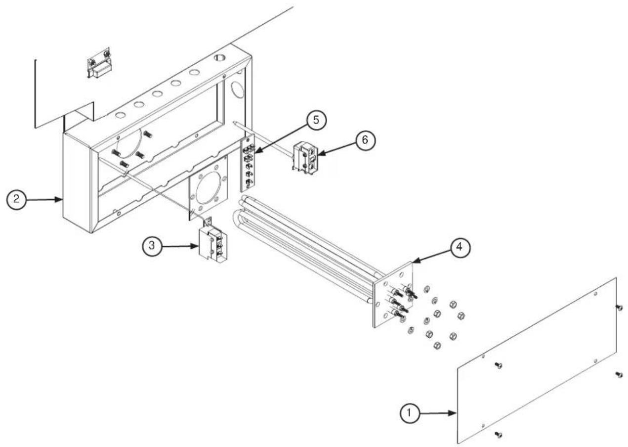
| ITEM QTY | DESCRIPTION | PART NUMBER | |
| 1 1 Heater | Box Cover 05 | 700-002-02-04 | |
| 2 1 Heater | Box 05700-00 | 2-98-38 | |
| 3 | 1 | Thermostat, High Limit | 05930-011-49-43 |
| 1 | Fitting, 1/4", Imperial Brass | 05310-924-02-05 | |
| 4 1 Heater See next page. | |||
| 5 1 Terminal Board 05940-002-78-97 | |||
| 6 | 1 | Kit, Wash Regulating Thermostat (CE Series) | 06401-003-18-20 |
| 1 | Kit, Wash Regulating Thermostat (CS Series) | 06401-003-18-21 | |
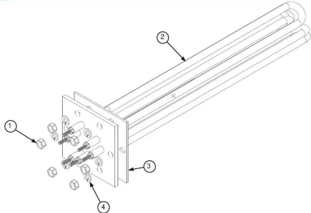
| ITEM QTY | DESCRIPTION | PART NUMBER | |
| 1 5 5/16-18 | Hex Nut 0531 | 10-275-01-00 | |
| 2 1 Heater | See tables below. | ||
| 3 1 Heater | Gasket 05330 | -200-02-70 | |
| 4 2 5/16" Lockwasher 05311-275-01-00 | |||
HIGH HOOD MODELS*
| VOLTS kW | PHASE PART NUMBER | |
| 208 18 | 1 | 04540-121-79-30 |
| 230 18 | 1 | 04540-121-79-31 |
| 208 18 | 3 | 04540-121-79-30 |
| 230 18 | 3 | 04540-121-79-31 |
| 460 18 | 3 | 04540-121-79-32 |
HEATERS
LOW HOOD MODELS*
| VOLTS kW | PHASE PART NUMBER | |
| 208 15 | 1 | 04540-121-68-45 |
| 230 15 | 1 | 04540-121-68-46 |
| 208 15 | 3 | 04540-121-68-45 |
| 230 15 | 3 | 04540-121-68-46 |
| 460 15 | 3 | 04540-121-68-47 |
*Steam models do not use electric heaters.
NOTICE When replacing a heater, it is HIGHLY recommended that the heater gasket be changed as well. Once installed, gaskets become compressed and are subjected to extreme temperature changes. Replacing the gasket when replacing the heater can prevent future leaks.
NOTICE The nuts used to secure the heater to the tub should be torqued to 16 in-lbs. After tightening, the unit should be allowed to heat-up and operate normally for approximately 30 minutes. Secure power to the machine and check the nuts once more to ensure that they are torqued to 16 in-lbs.
HEATER SYSTEM TROUBLESHOOTING
The wash tank heater system is electrically-connected in the circuit and is dependent upon the machine being properly filled with water and maintaining a safe water level. The system consists of two thermostats (mounted in the heater box behind the dress panel), a float switch (mounted in the wash tank), the heater relay (mounted in control box), and the heater which is activated by the thermostats.
Once the dishmachine has filled to the correct level, the heater should operate automatically. Should the tank heat be too high or too low or if there is no indication of temperatures at all, the following checks should be made by an authorized service agent or electrician:
Heater System Check
- If the temperature is too high, adjust thermostat using instructions on the next page.
- If temperature is too low, adjust thermostat as above, then:
- Turn off power to machine by placing customer's circuit breaker in the "OFF" position. Turn off machine circuit breaker located on right side of control box.
- Remove cover from control box on top of machine.
- Make sure water temperature is below 140^ F (preferably about 130^ F).
- Turn on both circuit breakers. Observe heater relay (R1) while the power switch is turned "ON" and "OFF." If relay contacts move in and out, the heater relay is operating correctly. Based on results, follow the appropriate section below (Relay Closes if contacts move in and out, Relay Does Not Close if contacts do not move in and out).
Relay Closes
- Check power supply at incoming terminal board (L1, L2, L3). It should be the same voltage as indicated on the machine data plate.
- Check power at connections on heater relay (R1). The voltage should agree with the voltage on the machine data plate. If not, check wires for breaks or bad connections.
- Check power at terminals of heater, which should agree with the data plate. If not, check wires for breaks or bad connections.
- Temperatures should rise as explained in Step 1 of the Relay Does Not Close section below, and amperage can be checked according to those instructions. Replace any defective elements.
Relay Does Not Close
- There is an insulated movable bar on the relay across the top. With an insulated probe, depress this bar and observe the thermometer: the temperature should rise noticeably in a minute or two. If it moves slowly, the element is probably faulty. If it moves constantly higher at a good rate, the element should be good.
NOTICE A check with an amp-probe at heater relay (R1) terminals should be made to verify the amp draw on each leg. This should be appropriate for the voltage and phase indicated on the data plate.
HEATER PROTECTION AND AUTOMATIC FILL (FOR UNITS EQUIPPED WITH AUTOMATIC FILL)
This control is activated when the power switch is turned “ON.” The primary function is to automatically energize the wash tank heating circuit. It will also cut-off the wash tank heating circuit should the water be accidentally drained from the machine with the power switch still “ON.” The power switch should always be turned-off before draining the unit.
This water level control consists of two floats that operate when the power switch is turned "ON" and works in conjunction with the thermostats and heater relays.
When the power switch is turned "ON," water starts to enter the dishmachine. When it reaches the proper level, the normally-open contacts in the water level float switch close, activating the heating circuit for tank heat.
If the water level falls below the correct level while power is still on, the float switch will sense the lack of water and deactivate the heater.
THERMOSTATS
The thermostat range is from 140°F to 240°F with a maximum bulb-exposure temperature of 300°F.
Calibration:
Wash Thermostat: Setpoint: 165°F (Adjustable range)
High-Limit Thermostat: Fixed setpoint: 210°F (Non-adjustable)
The high-limit thermostat is used to protect the heater element in the event of a run-away regulating thermostat or a dry-fire situation. It is set for 210^ + 0^ or -10^ with a fixed setpoint. This part is not adjustable.
The wash tank regulating thermostat will maintain the correct wash water temperature to meet regulatory requirements. These specify that the wash be no lower than 140^ F on chemical-sanitizing machines and no lower than 160^ F on hot-water-sanitizing machines.
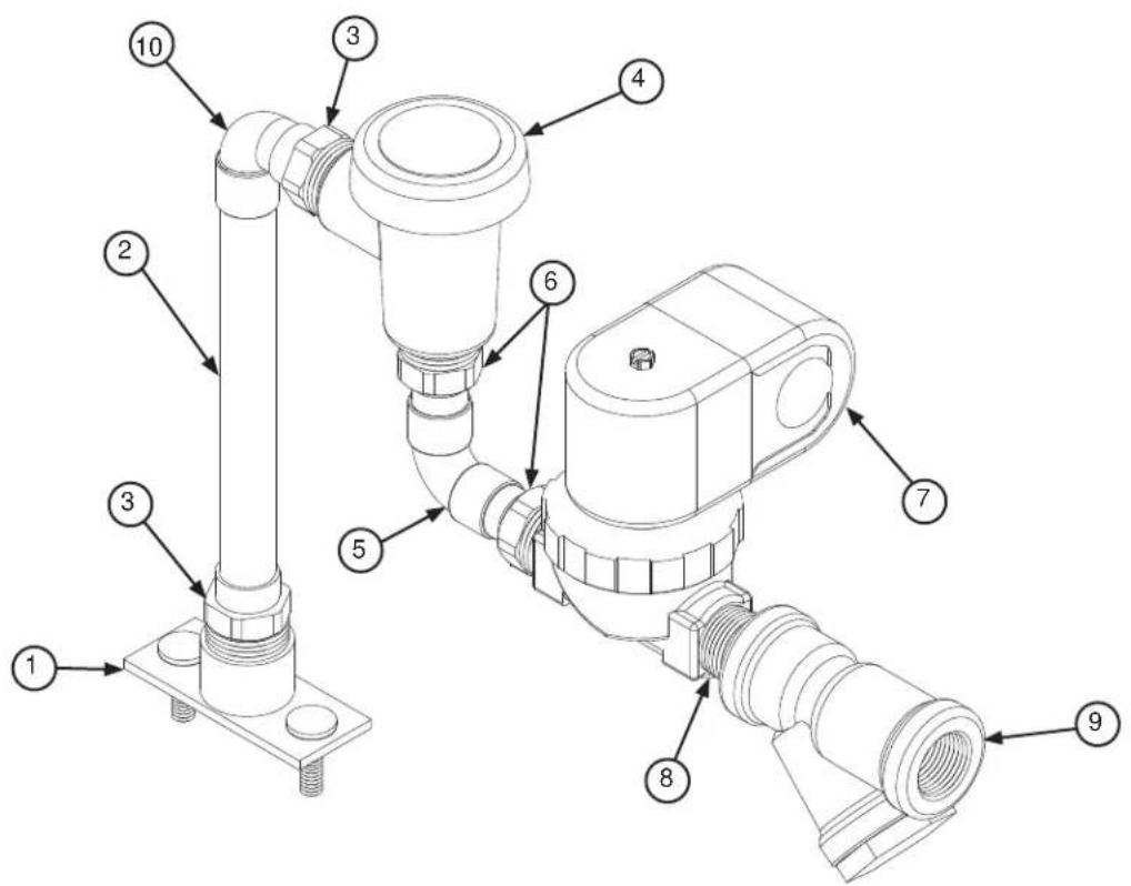
| ITEM QTY | DESCRIPTION | PART NUMBER | |
| 1 | 1 | Fill Line Injector | 05700-002-04-71 |
| 1 | Gasket, Fill Line Injector | 05330-111-42-81 | |
| 2 1 Tube, Copper, 1/2" | 0 | 5700-002-04-93 | |
| 3 2 Adapter, Male | 04730 | -401-03-01 | |
| 4 1 Vacuum | Breaker | 04820-003-06-13 | |
| 5 1 Elbow, 1/2" | 04730-4 | 06-01-01 | |
| 6 2 Adapter, 1/2" | 04730 | -011-59-53 | |
| 7 1 Valve, Solenoid, 1/2" | 110 V | 04810-100-12-18 | |
| 8 1 Nipple, 1/2", Close, Brass | 04730-207-15-00 | ||
| 9 1 Y-strainer, 1/2" | 04730-217-01-10 | ||
| 10 1 Elbow, 1/2" | 04730-406-31-01 |
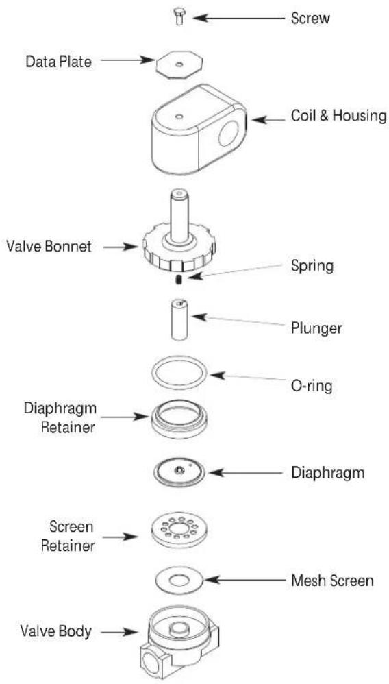
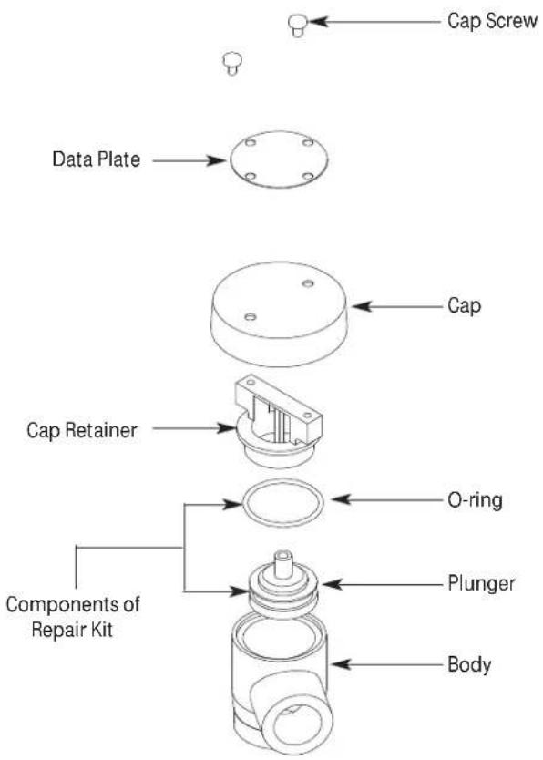
Solenoid Valve Plunger Kit
Includes plunger and spring
06401-003-07-40
Solenoid Valve Diaphragm Kit
Includes diaphragm and o-ring
06401-003-07-41
Solenoid Valve 110 V Coil and Housing Kit
06401-003-07-43
Complete Solenoid Valve
04810-100-12-18
Vacuum Breaker Repair Kit
06401-003-06-23
Complete Vacuum Breaker Assembly
04820-003-06-13
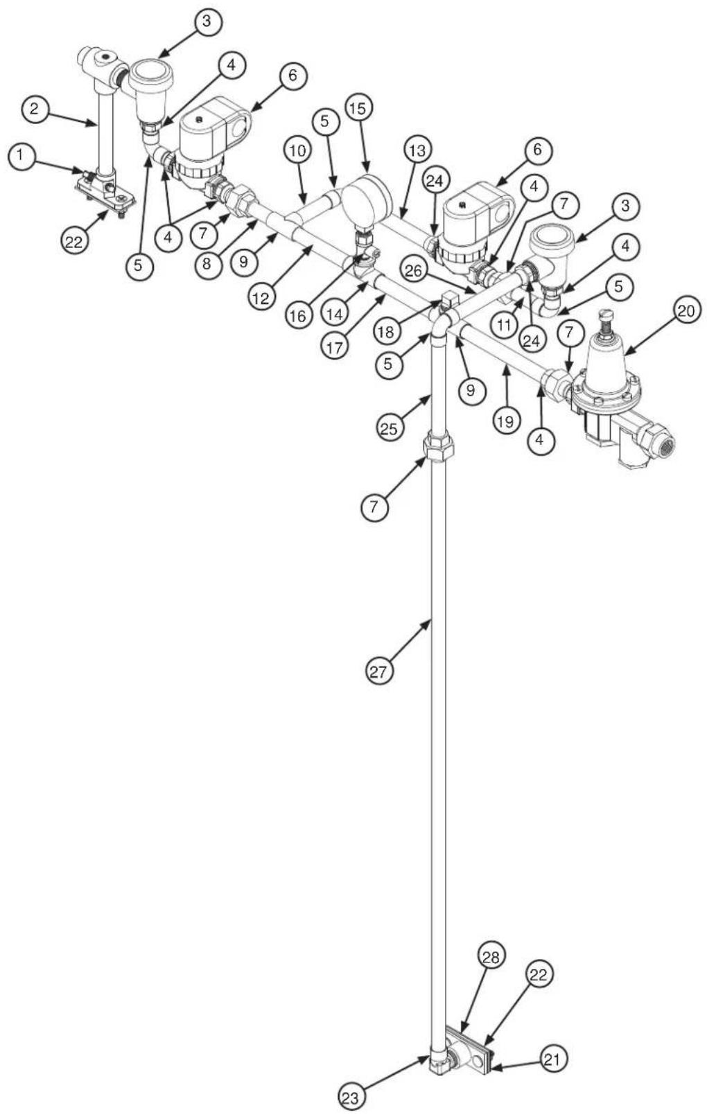
| ITEM QTY | DESCRIPTION | PART NUMBER | |
| 1 2 Plug, 1/8", Brass 047 | 30-209-07-37 | ||
| 2 | 1 | Rinse Injector | 05700-002-03-42 |
| 1 | Gasket, Rinse Injector | 05330-111-42-81 | |
| 3 2 Vacuum | Breaker, 1/2" | 04820-003-06-13 | |
| 4 6 Adapter | 1/2" 04730-011-59-53 | ||
| 5 3 Elbow, 1/2" | 04730-406-01-01 | ||
| 6 2 Valve, Solenoid, 1/2" | 04810-100-12-18 | ||
| 7 4 Union, 1/2" | 04730-412-05-01 | ||
| 8 1 Tube, Copper, 1/2" x | 2" See note below. | ||
| 9 1 Tee, Copper, 1/2" 047 | 30-411-01-01 | ||
| 10 1 Tube, Copper, 1/2" x | 3.06" | See note below. | |
| 11 | 1 | Tube, Copper, 1/2" x 2.08" | See note below. |
| 12 1 Tube, Copper, 1/2" x | 4" See note below. | ||
| 13 1 Tube, Copper, 1/2" x | 5.27" | See note below. | |
| 14 2 Tee, 1/2" x 1/2" x 1/4" | 04730-411-25-01 | ||
| 15 | 1 | Gauge, Pressure, 0-100 PSI | 06685-111-88-34 |
| 1 | Decal, 15-25 PSI | 09905-002-97-74 | |
| 16 1 Valve, Ball, 1/4" | 04810-011-72-67 | ||
| 17 1 Tube, Copper, 1/2" x | 4.185" | See note below. | |
| 18 1 Plug, 1/4", Brass 047 | 730-209-01-00 | ||
| 19 1 Tube, Copper, 1/2" x | 5.92" | See note below. | |
| 20 | 1 | Pressure Regulator, 1/2" (Not Used on GP Units) | 04820-100-04-07 |
| 1 | Elbow, 90-degree, 1/2" Brass (GP Units Only, Not Shown) | 04730-206-08-00 | |
| 21 1 Plate, Rinse Plumbing | 05700-011-82-86 | ||
| 22 2 Gasket | 05330-111-42-81 | ||
| 23 1 Elbow, 90-degree, 1/2" | 04730-406-32-01 | ||
| 24 2 Adapter, Male | 04730-401-03-01 | ||
| 25 1 Tube, Copper, 1/2" x | 5.75" | See note below. | |
| 26 1 Tube, Copper, 1/2" x | 4.75" | See note below. | |
| 27 1 Tube, Copper, 1/2" x | 40" (High Hood), 1/2" x 33" (Low Hood) | See note below. | |
| 28 1 Plate, Deflector 057 | 00-002-62-49 | ||
NOTICE Copper tubing should be purchased locally and cut to the length shown in the part description.
Complete Steam Coil Assembly 05700-002-11-78
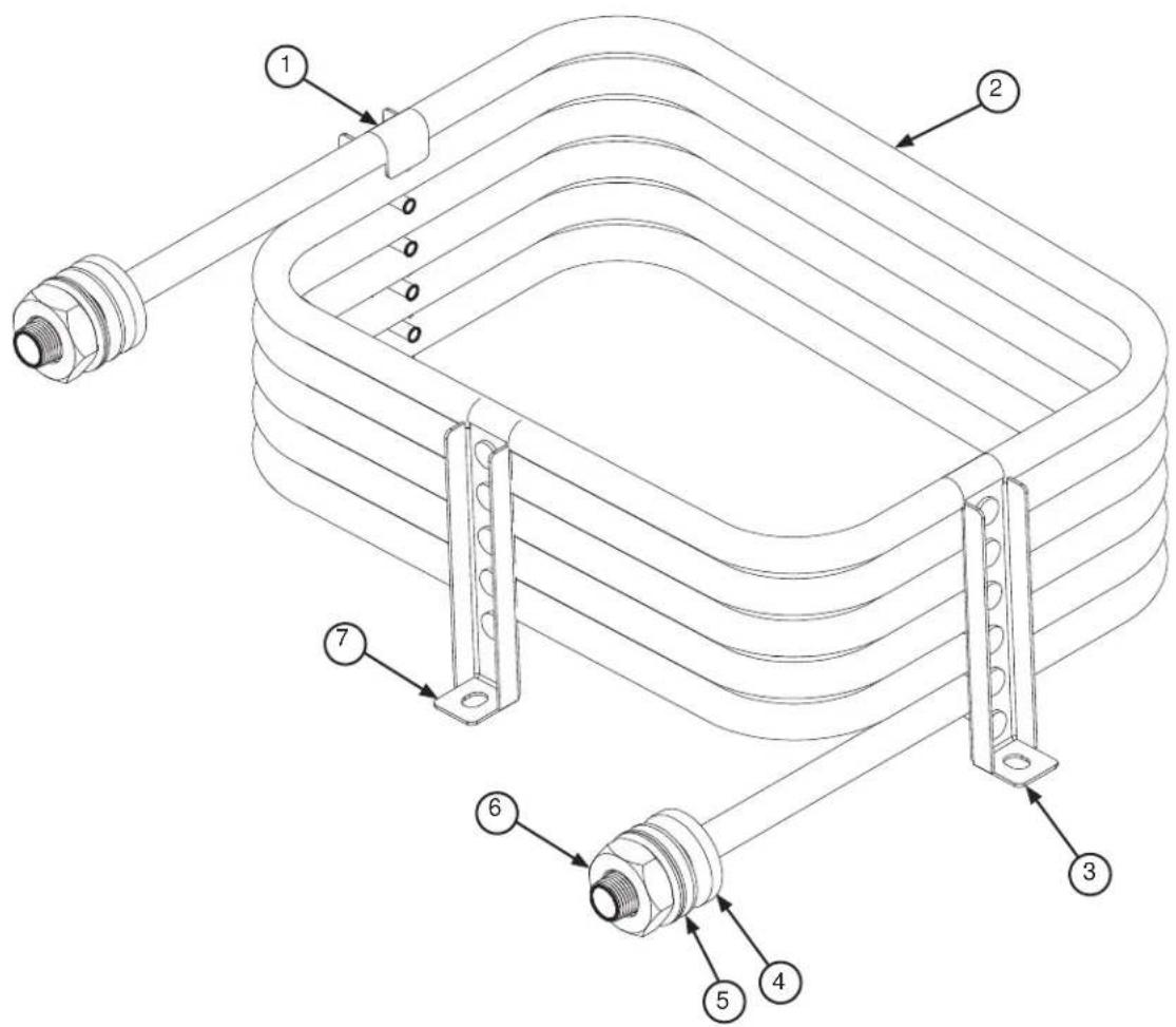
| ITEM QTY DESCRIPTION PART NUMBER | |
| 1 1 Stand "D" 05700-002-74-85 | |
| 2 1 Steam Coil 05700-002-84-03 | |
| 3 1 Stand "C" 05700-002-74-84 | |
| 4 1 Coil Gasket 05700-001-17-86 | |
| 5 1 Flat Washer 05700-001-17-87 | |
| 6 1 Coil Nut 05310-011-17-85 | |
| 7 1 Stand "B" 05700-002-74-83 |
NOTICE The Coil Gasket should be replaced any time the Steam Coil is replaced or removed for an extended period of time.
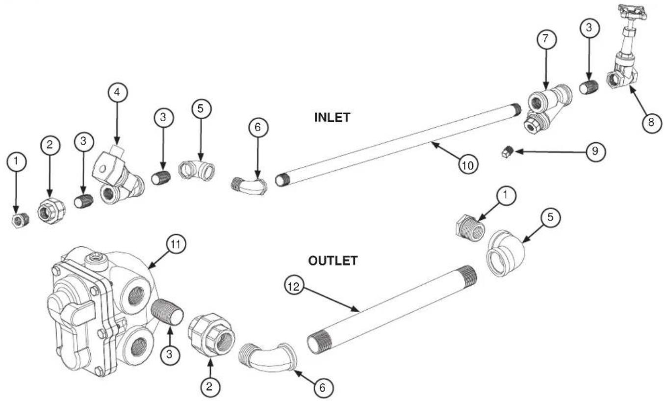
| ITEM QTY | DESCRIPTION | PART NUMBER | |
| 1 2 Reduce, 3/4" to 1/2", Black Iron 04730-911-02-34 | |||
| 2 2 Union, 3/4", Black Iron 04730-912-01-00 | |||
| 3 4 Nipple, Close, 3/4", Black Iron 04730-907-01-00 | |||
| 4 1 Valve, Steam Solenoid, 3/4", 120 V 04820-011-87-39 | |||
| 5 2 Elbow, 90-degree, 3/4", Black Iron 04730-906-10-34 | |||
| 6 2 Elbow, Street, 90-degree, 3/4", Black Iron 04730-011-87-37 | |||
| 7 1 Y-strainer, 3/4", Black Iron 04730-217-01-32 | |||
| 8 1 Valve, Gate, Steam, 3/4" 04820-100-19-00 | |||
| 9 1 Plug, 3/8", Black Iron 04730-909-02-34 | |||
| 10 | 1 Pipe, 3/4" x 32" Long, Black Iron 04730-002-21-27 | ||
| 11 | 1 | Steam Trap, 3/4" | 06680-500-02-77 |
| 12 | 1 Pipe, 3/4" x 10" Long, Black Iron 04730-907-06-34 | ||
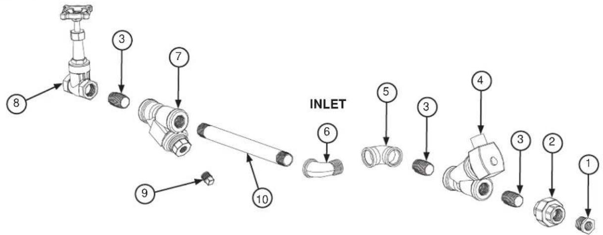
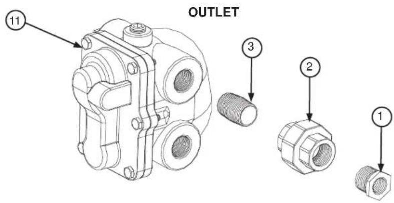
| ITEM QTY | DESCRIPTION | PART NUMBER | |
| 1 2 Reducer, 3/4" to 1/2" | Black Iron 04730-911-02-34 | ||
| 2 2 Union, 3/4", Black Iron | 04730-912-01-00 | ||
| 3 4 Nipple, Close, 3/4", Black Iron 04730-907-01-00 | |||
| 4 1 Valve, Steam Solenoid, 3/4", 120 V 04820-011-87-39 | |||
| 5 1 Elbow, 90-degree, 3/4", Black Iron 04730-906-10-34 | |||
| 6 1 Elbow, Street, 90-degree, 3/4", Black Iron 04730-011-87-37 | |||
| 7 1 Y-strainer, 3/4", Black Iron 04730-217-01-32 | |||
| 8 1 Valve, Gate, Steam, 3/4" 04820-100-19-00 | |||
| 9 1 Plug, 3/8", Black Iron | 04730-909-02-34 | ||
| 10 | 1 Pipe, 3/4" x 32" Long, Black Iron | 04730-002-21-27 | |
| 11 | 1 | Steam Trap, 3/4" | 06680-500-02-77 |
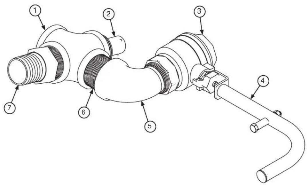
| ITEM QTY | DESCRIPTION | PART NUMBER | |
| 1 1 Cross | Connector, 1 1/2" | 04710-004-43-65 | |
| 2 1 Nipple, | Rinse 05700- | 021-84-61 | |
| 3 1 Ball Valve, | 1 1/2" 048 | 20-111-71-46 | |
| 4 1 C-44 Ball Valve Handle Assembly 05700-021-84-74 | |||
| 5 1 Elbow, | 1/2", 90-degree, Street Brass 04730-206-32-00 | ||
| 6 1 Nipple, | 1 1/2", Close | Brass 04730-207-40-00 | |
| 7 1 Fitting, | Barbed, 1 1/2' x 1 1/2" 04730-011-69-92 | ||
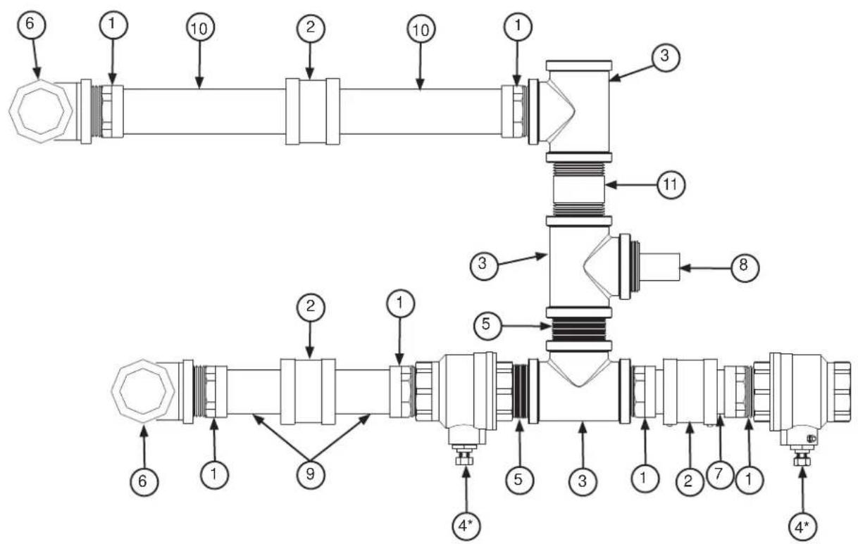
| ITEM QTY | DESCRIPTION | PART NUMBER | |
| 1 6 Adapter | Male to Female | 1 1/2" 04730-401-25-01 | |
| 2 3 No-hub | Connector 04 | 720-604-06-00 | |
| 3 3 Tee, Brass | 1 1/2" 04 | 730-011-69-93 | |
| 4 | 2 | Ball Valve, 1 1/2"Valve Handle Assembly (Not Shown) | 04820-011-71-4606401-021-84-74 |
| 2 | |||
| 5 2 Nipple, | Close Brass, | 1 1/2" 04730-207-40-00 | |
| 6 2 Elbow, | Brass, 90-degree, | 1 1/2" 04730-011-73-77 | |
| 7 2 Tube, | Copper, 1 1/2" | x 1 3/4" (All Models) See note below. | |
| 8 1 Nipple, | Rinse 05700- | 021-84-61 | |
| 9 | 2 | Tube, Copper, 1 1/2" x 3 1/2" (C-66), 1 1/2" x 6 1/2" (C-76)1 1/2" x 10 1/4" (C-80), 1 1/2" x 11 1/2" (C-90) | See note below. |
| 10 | 2 | Tube, Copper, 1 1/2" x 7 1/2" (C-66), 1 1/2" x 10 1/4" (C-76)1 1/2" x 14" (C-80), 1 1/2" x 15 1/4" (C-90) | See note below. |
| 11 | 1 | Nipple, Brass, 1 1/2" x 3" | 04730-011-87-04 |
NOTICE Copper tubing should be purchased locally and cut to the length shown in the part description.
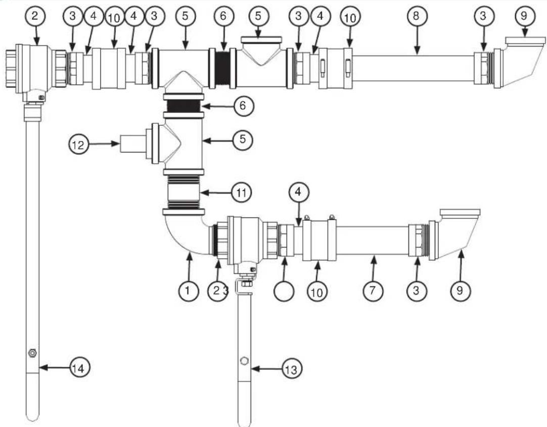
| ITEM QTY | DESCRIPTION | PART NUMBER | ||
| 1 1 Elbow, 1 | 1/2", Street | Brass 04730-206-32-00 | ||
| 2 2 Ball Valve, 1 | 1 1/2" 048 | 20-011-71-46 | ||
| 3 6 Adapter | Male to Female, 1 | 1 1/2" 04730-401-25-01 | ||
| 4 4 Tube, Copper, 1 | 1 1/2" x 1 | 7/8" (All Models) See note below. | ||
| 5 3 Tee, Brass, 1 | 1 1/2" 04 | 730-011-69-93 | ||
| 6 2 Nipple, Close Brass, | 1 1/2" 04730-207-40-00 | |||
| 7 | 2 | Tube, Copper, 1 1/2" x 5 | 3/16" (C-66), 1 1/2" x 10 | 3/16" (C-76) |
| 1 1/2" x 14 | 3/16" (C-80), 1 1/2" x 19 | 3/16" (C-90) | ||
| 8 | 2 | Tube, Copper, 1 1/2" x 8 | 1/8" (C-66), 1 1/2" x 13 | 1/8" (C-76) |
| 1 1/2" x 17 | 1/8" (C-80), 1 1/2" x 22 | 1/8" (C-90) | ||
| 9 2 Elbow, Brass, 90-degree, 1 1/2" 04730-011-73-77 | ||||
| 10 3 No-hub Connector | 04720-604-06-00 | |||
| 11 | 1 | Nipple, Brass, 1 1/2" x 3" | 04730-011-87-04 | |
| 12 1 Nipple | Rinse | 05700-021-84-61 | ||
| 13 1 Valve | Handle Assembly | 05700-021-84-74 | ||
| 14 1 Valve | Handle Assembly | 05700-002-57-82 | ||
NOTICE Copper tubing should be purchased locally and cut to the length shown in the part description.
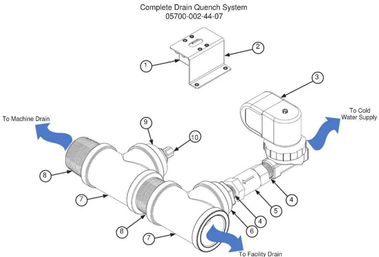
From the existing drain, attach the two additional Tees (Item 7) using the 1 1/2" Close Brass Nipples (Item 8). Tighten the Reducers (Items 6 and 9) into the Tees as shown above. Attach the Modified Compression Fitting (Item 10) into the 1 1/2" to 1/4" Reducer (Item 9). Position the bulb of the thermostat (Item 1) so that it rests approximately 1/4" from the bottom of the Tee (Item 7). Tighten the Modified Compression Fitting (Item 10) as required.
Mount the Thermostat (Item 1) to the tub using the Thermostat Bracket (Item 2) and set it for 120°F - 140°F. Install the Solenoid Valve (Item 3) to the second Tee (Item 7) and then attach to the incoming cold water line. Use thread tape as required to prevent any leaks.
| ITEM QTY DESCRIPTION PART NUMBER | |
| 1 1 Thermostat 05930-121-67-72 | |
| 2 1 Thermostat Bracket 05700-011-81-64 | |
| 3 1 Solenoid Valve 04810-100-12-18 | |
| 4 2 Nipple, Close Brass, 1/2" 04730-207-15-00 | |
| 5 1 Valve, Check, 1/2" 04820-002-55-77 | |
| 6 1 Reducer, 1 1/2" to 1/2" 04730-002-55-75 | |
| 7 2 Tee, 1 1/2" x 1 1/2" x 1 1/2" 04730-011-69-93 | |
| 8 2 Nipple, Close Brass, 1 1/2" 04730-207-40-00 | |
| 9 1 Reducer, 1 1/2" to 1/4" 04730-002-55-76 | |
| 10 1 Modified Compression Fitting 05700-001-16-52 |
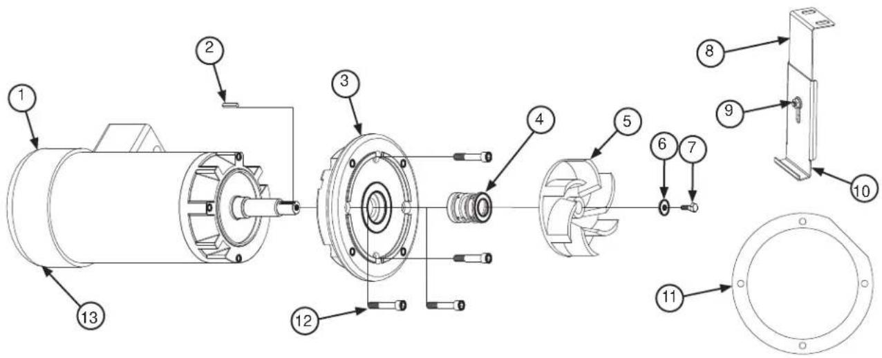
| ITEM QTY | DESCRIPTION | PART NUMBER | |
| 1 1 Motor S | See table on the next page. | ||
| 2 1 Key, 3/1 | 6" x 1" 05700-011-89-17 | ||
| 3 1 Pump P | late 05700-021-71-83 | ||
| 4 1 Pump S | seal 05330-01 | 1-71-98 | |
| 5 | 1 | Impeller (C-44/54) | 05700-031-67-45 |
| 1 | Impeller (C-66/76/80/90) | 05700-031-71-78 | |
| 6 1 Impeller | Washer 057 | 00-011-71-95 | |
| 7 1 Bolt, Hex | Head 1/4-20 x 3/4" 05305-004-42-64 | ||
| 8 1 Upper S | Support Bracket | 05700-021-73-68 | |
| 9 1 Nut, 1/4 | -20 Serrated | 05310-011-66-49 | |
| 10 1 Lower | Support Bracket | 05700-021-73-71 | |
| 11 | 1 | Motor Mounting Gasket | 05330-011-71-62 |
| 12 1 Cap S | crew, 3/8-16 x 2" | 05305-011-74-98 | |
| 13 1 Motor | Mounting Clamp, 4 1/8" - 7" (Not Shown) | 04730-002-32-15 | |
Complete Motor Bracket Assembly
Items 8,9, and 10
05700-021-73-42
WASH MOTORS
| Volts Phase Hz Motor Part Number Complete Kit Part Number | |
| 200-440 3 50 06105-121-81-34 06401-003-09-96 | |
| 208-230 1 60 06105-021-70-57 06401-003-09-97 | |
| 200-230 3 60 06105-121-70-58 06401-003-09-98 | |
| 380 3 60 06105-121-81-34 06401-003-09-96 | |
| 460 3 60 06105-121-70-58 06401-003-09-97 | |
| 600 3 60 06105-002-48-31 06401-003-09-98 |
PRE-WASH MOTORS
C-66/76
| Volts Phase Hz Motor Part Number Complete Kit Part Number | |
| 208-230 3 50 06105-121-70-56 06401-003-10-38 | |
| 380 3 50 06105-121-81-34 06401-003-10-39 | |
| 415 3 50 06105-121-81-34 06401-003-10-39 | |
| 440 3 50 06105-121-70-56 06401-003-10-38 | |
| 208-230 1 60 06105-121-70-55 06401-003-10-40 | |
| 200-230 3 60 06105-121-70-56 06401-003-10-38 | |
| 380 3 60 06105-121-70-56 06401-003-10-38 | |
| 460 3 60 06105-121-70-56 06401-003-10-38 | |
| 600 3 60 06105-002-48-31 06401-003-10-41 |
C-80/90
| Volts Phase Hz Motor Part Number Complete Kit Part Number | |
| 208-230 3 50 06105-121-81-34 06401-003-10-39 | |
| 380 3 50 06105-121-81-34 06401-003-10-39 | |
| 415 3 50 06105-121-81-34 06401-003-10-39 | |
| 440 3 50 06105-121-81-34 06401-003-10-39 | |
| 208-230 1 60 06105-021-70-57 06401-003-10-42 | |
| 200-230 3 60 06105-121-70-58 06401-003-10-43 | |
| 380 3 60 06105-121-81-34 06401-003-10-39 | |
| 460 3 60 06105-121-70-58 06401-003-10-43 | |
| 600 3 60 06105-002-48-31 06401-003-10-41 |
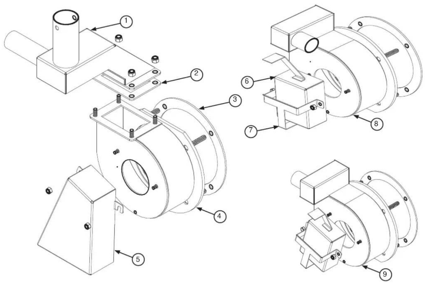
| ITEM QTY | DESCRIPTION | PART NUMBER | |
| 1 1 Pump | Discharge 057 | 00-002-50-90 | |
| 2 1 Gasket | 05330-002-54-55 | ||
| 3 1 Motor | Mounting Gasket | 05330-011-71-62 | |
| 4 1 Wash | Pump 05700-002-50-92 | ||
| 5 1 Intake | Suction Scoop | 05700-002-51-20 | |
| 6 1 Pre-wash | Intake Strainer | 05700-021-74-96 | |
| 7 1 Pre-wash | Strainer Bracket | 05700-021-74-94 | |
| 8 1 Pre-wash | Pump, C-66 | /76/80/90, L-R 05700-002-43-56 | |
| 9 1 Pre-wash | Pump, C-66 | /76/80/90, R-L 05700-002-42-69 |
Complete Lower Wash Arm Assembly, 50 Hz Machines 05700-002-24-86
Complete Lower Wash Arm Assembly, 60 Hz Machines 05700-031-74-66
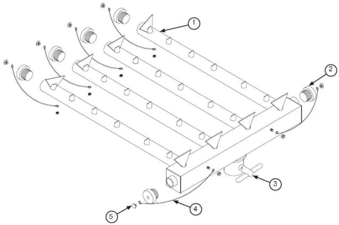
| ITEM QTY | DESCRIPTION | PART NUMBER | |
| 1 | 1 | Lower Wash Arm Manifold, 50 Hz Machines | 05700-002-24-87 |
| 1 | Lower Wash Arm Manifold, 60 Hz Machines | 05700-031-67-29 | |
| 2 | 6 | End-cap | 05700-011-67-11 |
| 6 | End-cap Replacement Kit* | 06401-003-10-19* | |
| 3 1 Manifold | Quick-Release | Key 05700-011-94-45 | |
| 4 6 Lanyard | 05340-011-72-46 | ||
| 5 6 Mounting | Screw, End-cap, 10-32 x 3/8" 05305-173-12-00 | ||
*The replacement kit for the end-cap includes the end-cap, lanyard, and mounting screw.
NOTICE When replacing the screws in the end-caps, use a thread-locking product to ensure the mounting screws do not come loose during operation.
Complete Pre-wash Arm Assembly 05700-021-74-65
Complete Upper Arm Assembly 05700-031-74-99
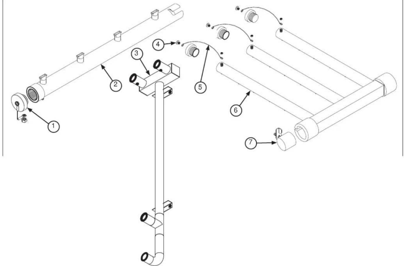
| ITEM QTY | DESCRIPTION | PART NUMBER | |
| 1 | 4 | End-cap | 05700-011-67-11 |
| 4 | End-cap Replacement Kit* | 06401-003-10-19* | |
| 2 1 Pre-wash Tube 05700-001-16-89 | |||
| 3 | 1 | Pre-wash Manifold, C-66/76/80/90 (High Hood) | 05700-002-59-51 |
| 1 | Pre-wash Manifold, C-66/76/80/90 (Low Hood) | 05700-002-42-76 | |
| 4 4 Mounting Screw, End-cap, 10-32 x 3/8" 05305-173-12-00 | |||
| 5 4 Lanyard 05340-011-72-46 | |||
| 6 1 Upper Wash Arm Manifold 05700-031-67-34 | |||
| 7 1 Cap, Wash Tube 05700-021-69-68 | |||
| 8 1 Upper Wash Manifold Support Bracket (Not Shown) 05700-021-73-97 | |||
*The replacement kit for the end-cap includes the end-cap, lanyard, and mounting screw.
NOTICE
When replacing the screws in the end-caps, use a thread-locking product to ensure the mounting screws do not come loose during operation.
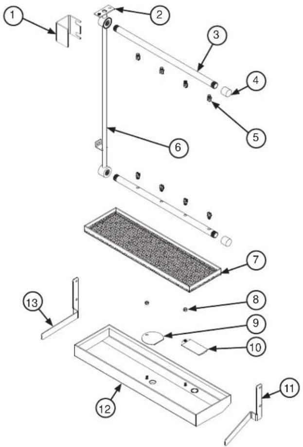
| ITEM QTY | DESCRIPTION | PART NUMBER | |
| 1 1 Rinse Arm Support Bracket 05700-002-06-24 | |||
| 2 1 Gasket, Final Rinse Manifold 05330-111-42-81 | |||
| 3 2 Rinse Arm 05700-002-02-18 | |||
| 4 2 End-cap 05700-002-02-19 | |||
| 5 8 Rinse Nozzle 04730-003-59-63 | |||
| 6 | 1 | Final Rinse Manifold (High Hood) | 05700-002-97-41 |
| 1 | Final Rinse Manifold (Low Hood) | 05700-002-03-08 | |
| 7 1 Rinse Pan Strainer 05700-041-85-09 | |||
| 8 2 Locknut 1/4-20 with Nylon Insert 05310-374-01-00 | |||
| 9 1 Rinse Drain Control Plate 05700-011-68-70 | |||
| 10 1 Rinse Drain Overflow Plate 05700-002-53-62 | |||
| 11 | 1 | Left Rinse Pan Locator Bracket | 05700-021-92-38 |
| 12 | 1 | Rinse Tray | 05700-002-51-18 |
| 13 1 Right Rinse Pan Locator Bracket 05700-021-92-37 | |||
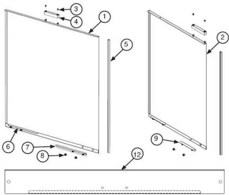
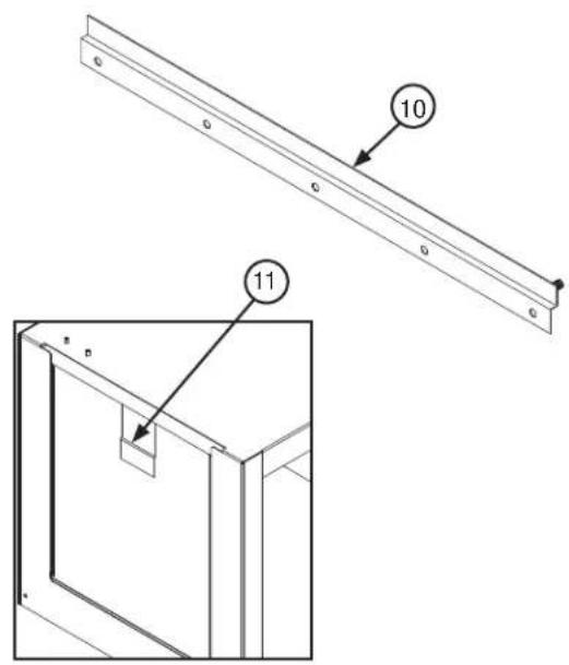
| ITEM QTY | DESCRIPTION | PART NUMBER | |
| 1 | 1 | Door (High Hood) | 05700-003-13-47 |
| 1 | Door (Low Hood) | 05700-002-94-04 | |
| 2 | 1 | Pre-wash Door, Left-to-Right (High Hood) | 05700-003-13-42 |
| 1 | Pre-wash Door, Left-to-Right (Low Hood) | 05700-002-43-65 | |
| 1 | Pre-wash Door, Right-to-Left (High Hood) | 05700-003-13-40 | |
| 1 | Pre-wash Door, Right-to-Left (Low Hood) | 05700-002-42-88 | |
| 3 1 Screw, 8-32 x 1/4" 05 | 305-172-09-00 | ||
| 4 1 Door Switch Magnet | 05700-111-51-68 | ||
| 5 | 2 | Door Guide (High Hood) | 05700-111-70-92 |
| 2 | Door Guide (Low Hood) | 05700-002-03-28 | |
| 6 1 Bracket. | Right Door Stop 05700-002-96-33 | ||
| 7 1 Bracket. | Left Door Stop 05700-002-96-32 | ||
| 8 4 Locknut. | 10-24 Hex with Nylon Insert 05310-373-01-00 | ||
| 9 2 Bracket. | Pre-wash Door Stop 05700-002-05-46 | ||
| 10 | 1 | Left Door Guide (High Hood) | 05700-002-32-51 |
| 1 | Right Door Guide (High Hood) | 05700-031-76-44 | |
| 11 1 Door Catch 05700-031-84-80 | |||
| 12 | 1 | Door Hood Support | 05700-031-84-13 |
| 1 | Pre-wash Door Hood Support | 05700-031-84-14 | |
| 13 1 Door Stiffener (Not Shown) 05700-031-83-43 | |||
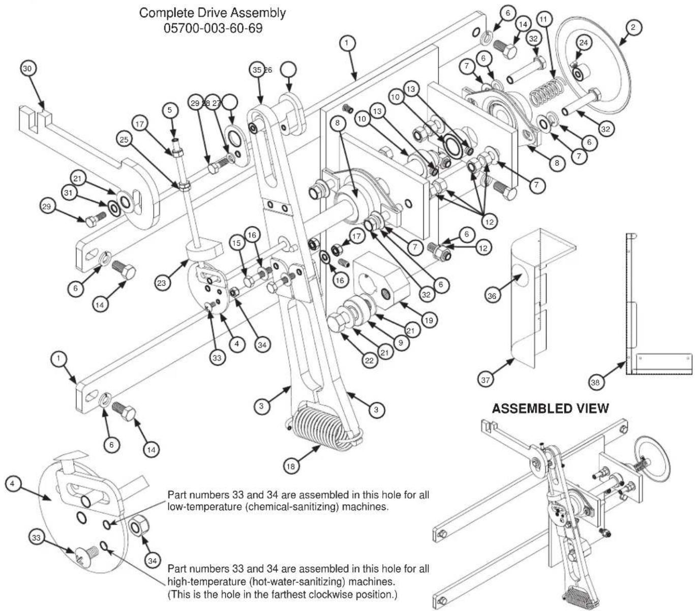
| ITEM QTY | DESCRIPTION | PART NUMBER | |
| 1 1 Mounting | Bracket Drive | Motor 05700-031-73-56 | |
| 2 1 Adjuster | Handle 05700 | 021-72-28 | |
| 3 2 Coupling & Expansion | Legs 05700 | 021-67-50 | |
| 4 1 Adjuster | Crank Assembly | 05700-021-69-95 | |
| 5 1 Adjuster | Scotch Yoke | 05700-021-69-76 | |
| 6 12 | Lockwasher, 3/8" | 05311-276-01-00 | |
| 7 8 Flat Washer, 3/8" | 05311-176-01-00 | ||
| 8 2 Block, Pillow | 03120-021-71-87 | ||
| 9 1 Bearing | Roller | 03120-011-71-81 | |
| 10 2 Collar, | Shaft Conve | or Drive 05700-011-89-18 | |
| 11 1 Spring, | Adjuster 053 | 15-011-71-90 | |
| 12 12 Nut, | Hex, 3/8-16 0 | 5310-276-01-00 | |
| 13 2 Set Screw, | 5/16-18 x 1/4" | 05305-002-98-39 | |
| 14 4 Bolt, 3 | 8-16 x 3/4" 0 | 5306-011-71-60 | |
| 15 2 Bolt, 1 | 4-20 x 1/4" 0 | 5305-274-22-00 | |
| 16 4 Washer, | 1/4-20 053 | 11-174-01-00 | |
| 17 3 Locknut, | 1/4-20 Hex | with Nylon Insert | 05310-374-01-00 |
| 18 1 Spring, | Drive | 05315-011-83-51 | |
| 19 1 Hub, | Drive | 05700-011-67-97 | |
| 20 1 Set Screw, | 1/4-20 x 1/2" | 05305-011-71-51 | |
| 21 3 Flat Washer, | 1/2" | 05311-011-71-93 | |
| 22 1 Bolt, 1 | 2-13 x 1 3/4" | 05305-011-71-94 | |
| 23 1 Plate, | Drive Rod 05 | 700-021-67-42 | |
| 24 1 Bolt, | 10-32 x 3/8" Hex Head | 05306-011-62-45 | |
| 25 2 Nut, | Hex, 1/4-20 05 | 310-274-01-00 | |
| 26 1 Socket, | Drive | 05700-021-67-39 | |
| 27 1 Plate, | Spacer | 05700-011-67-58 | |
| 28 1 Lockwasher, | Spring, 1/4" | 05311-274-01-00 | |
| 29 2 Bolt, | Hex Head 1/4-20 x 3/4" | 05305-004-42-64 | |
| 30 1 Casting, | Pawl Bar Drive Linkage | 09515-021-87-73 | |
| 31 1 Washer, | 5/16-18 05 | 311-175-01-00 | |
| 32 4 Bolt, 3 | 8-16 x 1 3/4" | 05306-011-36-94 | |
| 33 1 Screw, | 10-24 x 3/8" | 05305-173-03-00 | |
| 34 1 Locknut, | 10-24 Hex with Nylon Insert | 05310-373-01-00 | |
| 35 1 Drive Plate and Rod | 05700-021-67-44 | ||
| 36 | 1 | Decal, Drive Adjuster | |
| 37 1 Front Drive Motor Cover | 05700-031-69-39 | ||
| 38 1 Rear Drive Motor Cover | 05700-002-41-21 | ||
| 39 1 Gear Drive (Not Shown) | 06105-011-71-88 | ||
| Drive Motors | 1 Drive Motor (50 Hz Machines) | 06401-003-08-41 | |
| 1 Drive Motor (208-230 V, 60 Hz, Single-Phase Machines) | 06401-003-08-42 | ||
| 1 Drive Motor (208-230 V, 60 Hz, Three-Phase Machines) | 06401-003-08-40 | ||
| 1 Drive Motor (460 V, 60 Hz, Three-Phase Machines) | 06401-003-08-43 | ||
| 1 Drive Motor (600 V, 60 Hz, Three-Phase Machines) | 06401-002-48-32 | ||
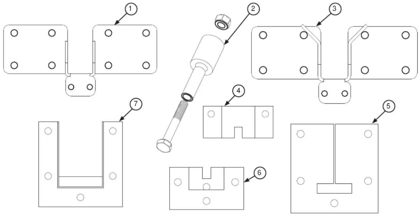
| ITEM QTY | DESCRIPTION | PART NUMBER | |
| 1 1 Pawl Bar | Bracket (No Tabs) | 05700-031-92-36 | |
| 2 1 Pawl Bar | Roller Replacement Kit | ^1 | 06401-003-11-80 |
| 3 1 Pawl Bar | Bracket (Tabs) | 05700-031-84-68 | |
| 4 | 1 | Top Guide Block | 05700-011-69-49 |
| 1 | Guide Block Replacement Kit^2 | 06401-003-10-15 | |
| 5 1 Pawl Bar | Gutter Gasket | 05330-011-68-55 | |
| 6 1 Bottom | Guide Block | 05700-011-69-50 | |
| 7 1 Pawl Bar | Gutter Replacement Kit | ^3 | 05700-021-74-94 |
^1 The Pawl Bar Replacement Kit contains the roller, roller shaft, and hardware.
^2 The Guide Block Replacement Kit contains the top guide block, bottom guide block, and gasket.
^3 The Pawl Bar Gutter Replacement Kit contains the weldment, gasket, and hardware.
NOTICE When replacing one guide block, the other guide block and the gasket should be replaced as well.
Complete C-44 Pawl Bar Assembly with Hardware 06401-131-81-00
Complete C-66 Pawl Bar Assembly with Hardware 06401-141-74-64
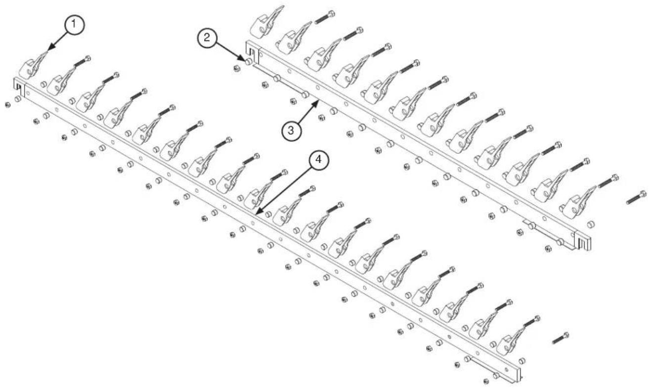
flowchart
graph TD
    A["1: Top Vehicle"] --> B["2: Mid-Section Vehicle"]
    B --> C["3: Left Side Vehicle"]
    C --> D["4: Right Side Vehicle"]
| ITEM QTY | DESCRIPTION | PART NUMBER | |
| 1 | 12 on C-4418 on C-66 | Pawl Bar Dog Casting 05700-021-69-00 | |
| 2 | 24 on C-4436 on C-66 | Pawl Bar Spacer 05700-011-71-45 | |
| 3 1 Pawl Bar (C-44) 05700-031-72-77 | |||
| 4 1 Pawl Bar (C-66) 05700-031-72-78 | |||
Complete C-80 Pawl Bar Assembly with Hardware, L-R 06401-131-81-06
Complete C-80 Pawl Bar Assembly with Hardware, R-L 06401-241-81-06
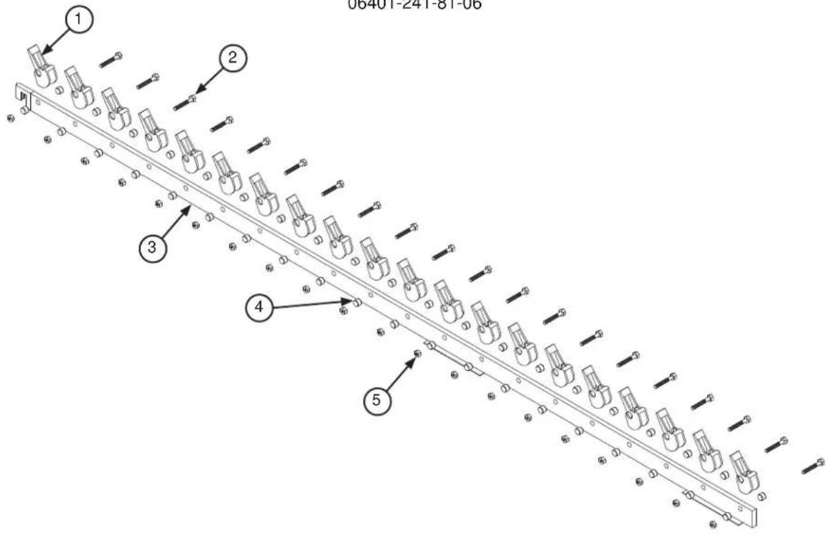
| ITEM QTY | DESCRIPTION | PART NUMBER | |
| 1 20 Pawl Bar Dog Casting | 1 | 05700-021-69-00 | |
| 2 20 Bolt, 3/8-16 x 1-3/4" Long 05700-011-71-45 | |||
| 3 | 1 | Pawl Bar (L-R) | 05700-031-74-19 |
| 1 | Pawl Bar (R-L) | 05700-041-82-01 | |
| 4 40 Pawl Bar Spacer 05700-011-71-45 | |||
| 5 20 Locknut, 3/8-16 with Nylon Insert 05700-011-72-55 | |||
When replacing pawl bar dog castings, ensure to re-install in the appropriate direction. If not, the rack will not be pulled through the machine during operation.
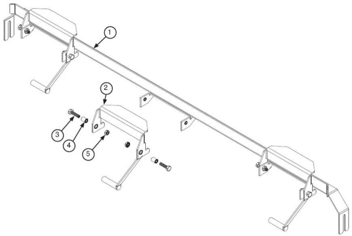
| ITEM QTY | DESCRIPTION | PART NUMBER | |
| 1 | 1 | Rack Rail | 05700-031-67-59 |
| 1 | Opposite Rack Rail | 05700-031-69-48 | |
| 2 | 3 | Actuator Switch | 05700-021-72-39 |
| Actuator Switch Replacement Kit^1 | 06401-003-10-14 | ||
| 3 6 Bolt, Hex Head 1/4-20 x | 3/4" 05305-004-42-64 | ||
| 4 6 Pawl Bar Spacer 05700- | 011-71-44 | ||
| 5 6 Locknut | 1/4-20 Hex with | Nylon Insert 05310-374-01-00 | |
^1 The Actuator Switch Replacement Kit contains the switch, two spacers, and hardware.
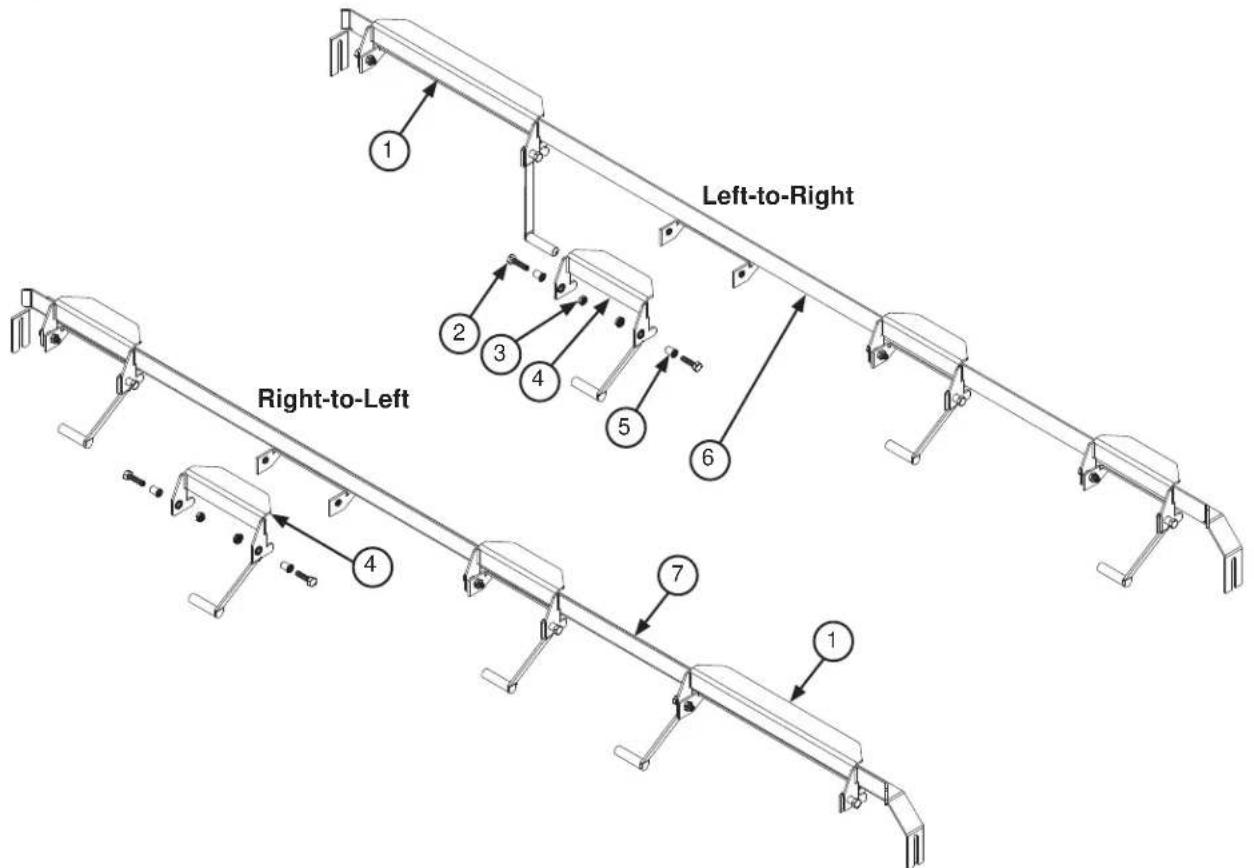
| ITEM QTY | DESCRIPTION | PART NUMBER | |
| 1 | 1 | Large Actuator Switch, L-RLarge Actuator Switch Replacement Kit, L-R ^1 | 05700-021-76-97 |
| 1 | Large Actuator Switch, R-LLarge Actuator Switch Replacement Kit, R-L ^1 | 06401-003-10-9905700-002-91-0906401-003-10-86 | |
| 2 8 per rail | Bolt, Hex Head | 1/4-20 x 3/4" 05305-004-42-64 | |
| 3 8 per rail | Locknut, 1/4-20 | Hex with Nylon Insert 05310-374-01-00 | |
| 4 3 per rail | Actuator SwitchActuator Switch Replacement Kit ^1 | 05700-021-72-3906401-003-10-14 | |
| 5 8 per rail | Pawl Bar Spacer | 05700-011-71-44 | |
| 6 | 1 | Rack Rail, L-ROpposite Rack Rail, L-R | 05700-031-76-2705700-041-71-37 |
| 7 | 1 | Rack Rail, R-LOpposite Rack Rail, R-L | 05700-031-76-2805700-041-69-54 |
^1 Actuator Switch Replacement Kits contain the switch, two spacers, and hardware.
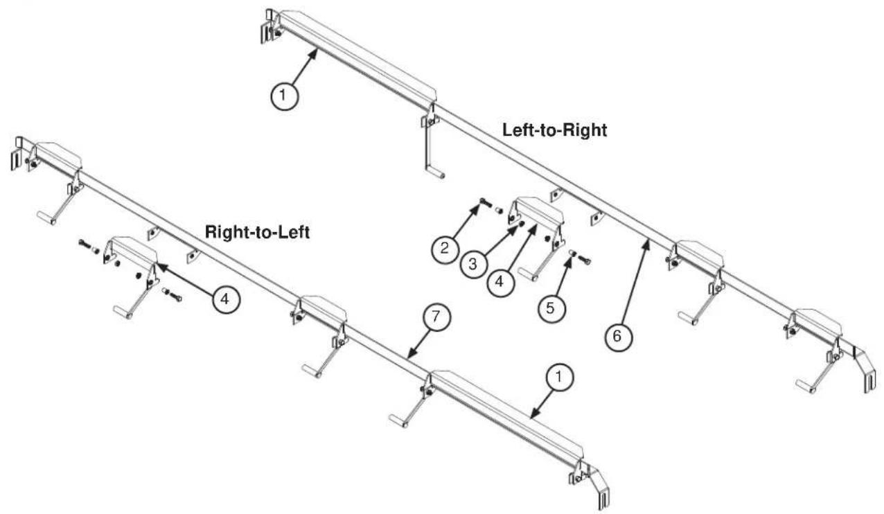
| ITEM QTY | DESCRIPTION | PART NUMBER | |
| 1 | 1 | Large Actuator Switch, L-R | 05700-021-77-01 |
| Large Actuator Switch Replacement Kit, L-R ^1 | 06401-003-10-83 | ||
| 1 | Large Actuator Switch, R-L | 05700-002-91-10 | |
| Large Actuator Switch Replacement Kit, R-L ^1 | 06401-003-10-85 | ||
| 2 8 per rail | Bolt, Hex Head | 1/4-20 x 3/4" 05305-004-42-64 | |
| 3 8 per rail | Locknut, 1/4-20 | Hex with Nylon Insert 05310-374-01-00 | |
| 4 3 per rail | Actuator Switch | 05700-021-72-39 | |
| Actuator Switch Replacement Kit ^1 | 06401-003-10-14 | ||
| 5 8 per rail | Pawl Bar Spacer | 05700-011-71-44 | |
| 6 | 1 | Rack Rail, L-R | 05700-031-81-53 |
| Opposite Rack Rail, L-R | 05700-041-74-13 | ||
| 7 | 1 | Rack Rail, R-L | 05700-031-81-54 |
| Opposite Rack Rail, R-L | 05700-041-74-14 |
Actuator Switch Replacement Kits contain the switch, two spacers, and hardware.
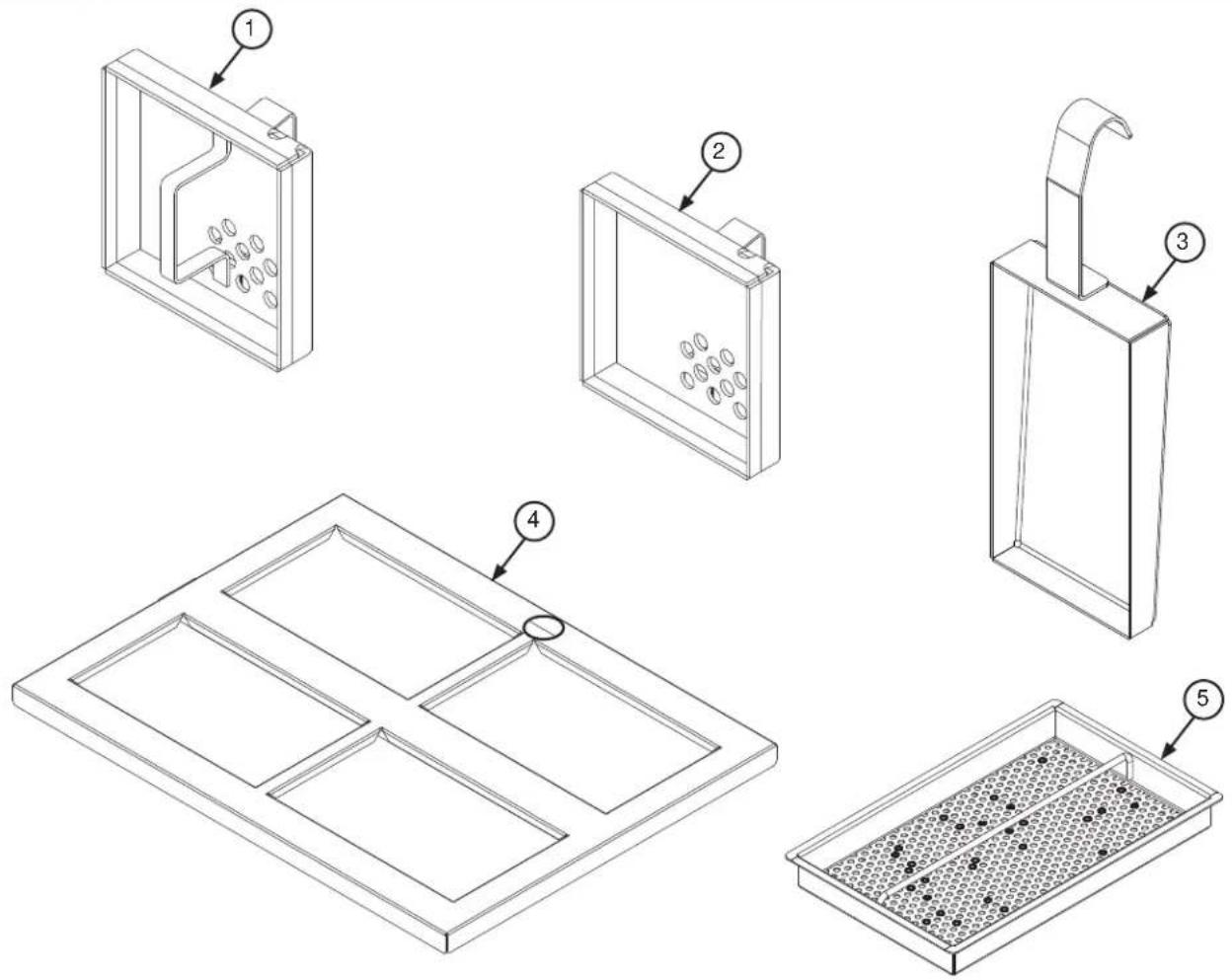
| ITEM QTY | DESCRIPTION | PART NUMBER | |
| 1 1 Drain G | Guard Strainer | 05700-002-09-15 | |
| 2 1 Screen | Strainer with | Handle 05700-002-09-04 | |
| 3 1 Wash Intake Strainer | 05700-001-22-23 | ||
| 4 1 Wash Strainer Separator | 05700-002-90-84 | ||
| 5 1 Tub Strainer | 05700-002-03-21 | ||
Complete Rinse Fill Motor Assembly 05700-002-40-25
Complete Rinse Fill Motor Assembly (C-66 L-R Only) 05700-002-48-22
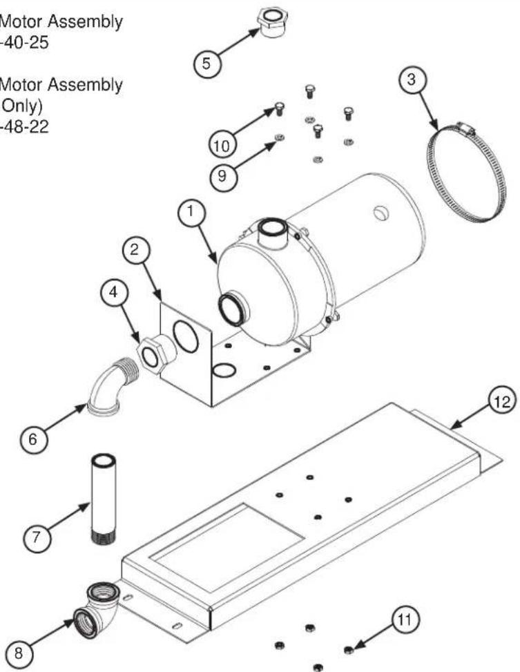
| ITEM QTY | DESCRIPTION | PART NUMBER | |
| 1 1 Motor 06 | 105-002-72 | 71 | |
| 2 1 Bracket | Pump Mounting | 05700-003-17-56 | |
| 3 1 Clamp | Hose 5 5/8" to 6" | 04730-011-34-90 | |
| 4 1 Reduce | Bushing, 1 1/4" to 1" | 04730-002-73-62 | |
| 5 1 Reduce | Bushing 1" to 3/4" | 04730-011-65-14 | |
| 6 1 Elbow, 90-Degree, 1' | Street Brass | 04730-002-11-99 | |
| 7 1 Nipple, 1" x 6" Brass | 04730-002-12-00 | ||
| 8 1 Elbow, 90-Degree, Brass Female | 04730-002-12-55 | ||
| 9 4 Lockwasher, 1/4" 05 | 311-274-01-00 | ||
| 10 | 4 Bolt, 1/4"-20 x 1/2" | 05305-274-02-00 | |
| 11 | 4 Nut, Hex 1/4-20 | 05310-274-01-00 | |
| 12 | 1 | Rinse Motor Mounting BracketRinse Motor Mounting Bracket (C-66 L-R Only) | 05700-002-38-9005700-002-39-33 |
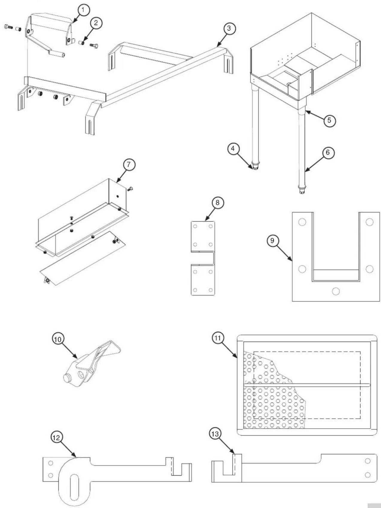
| ITEM QTY | DESCRIPTION | PART NUMBER | |
| 1 | 1 | Actuator Switch, Side-loaderActuator Switch Replacement Kit ^1 | 05700-002-91-1206401-003-10-64 |
| 2 1 Pawl Bar | Spacer 057 | 00-011-71-44 | |
| 3 | 1 | Track, Side-loader (L-R), 23"Track, Side-loader (R-L), 23"Track, Side-loader (L-R), 30"Track, Side-loader(R-L), 30" | 05700-031-78-9805700-031-95-2005700-003-04-5705700-003-04-58 |
| 4 1 Bullet Foot, Side-loader | 05340-108-01-03 | ||
| 5 1 Leg Socket Replacement Kit | 2 | 06401-003-09-79 | |
| 6 1 Leg Support Replacement Kit | 3 | 06401-003-09-80 | |
| 7 1 Vent Cowl Assembly for Hooded Side-loader 05700-003-15-66 | |||
| 8 1 Pawl Bar Roller Bracket 05700-031-77-94 | |||
| 9 1 Pawl Bar Gutter Replacement Kit | 4 | 06401-003-09-95 | |
| 10 1 Pawl Dog 05700-021-86-79 | |||
| 11 1 Front Strainer, Side-loader 05700-021-85-10 | |||
| 12 1 Drive Linkage Replacement Kit (L-R) | 5 | 06401-003-11-59 | |
| 13 1 Drive Linkage Replacement Kit (R-L) | 5 | 06401-003-11-60 | |
The Actuator Switch Replacement Kit contains the actuator, spacers, and hardware.
^2 The Leg Socket Replacement Kit contains the leg socket, set screw, and hardware.
^3 The Leg Support Replacement Kit contains the leg and bullet foot.
4The Pawl Bar Gutter Replacement Kit contains the pawl bar gutter, gasket, and hardware.
^5 The Drive Linkage Replacement Kits contain the drive linkages and hardware.
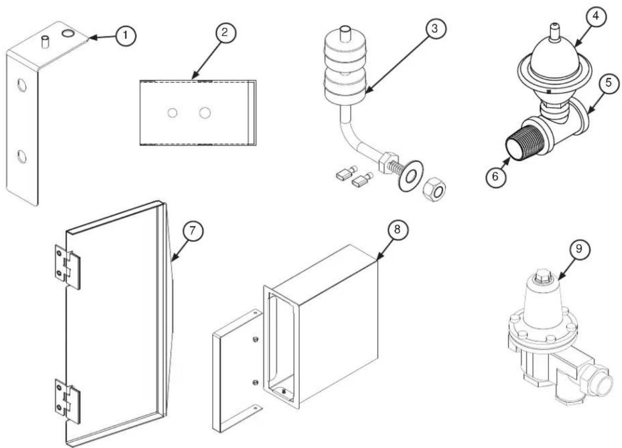
| ITEM QTY | DESCRIPTION | PART NUMBER | |
| 1 1 Float Switch Support | Bracket Replacement Kit1 | 06401-003-11-77 | |
| 2 1 Float Switch Cover 05700-021-75-71 | |||
| 3 | 1 | Wash Tank Float Switch | 06680-121-70-16 |
| 1 | Pre-wash Tank Float Switch | 06680-120-70-71 | |
| 4 | 1 | Water Arrestor, 1/2" | 06685-100-05-00 |
| Water Arrestor Repair Kit | 06401-003-06-23 | ||
| 5 1 Tee, 1/2" x 1/2" x 1/2", Water Arrestor 04730-211-27-00 | |||
| 6 1 Nipple, 1/2" Brass, Water Arrestor 04730-207-15-00 | |||
| 7 1 Scrap Basket Lid 05700-002-56-55 | |||
| 8 1 Scrap Basket Assembly 05700-002-11-21 | |||
| 9 1 Water Pressure Regulator, 1/2" 05700-100-04-07 | |||
^1 The Float Switch Support Bracket Replacement Kit contains the bracket and hardware.
NOTICE replacing a float switch, the flat washer goes inside against the tub while the nut goes on the outside of the tub.
07610-004-40-03-B
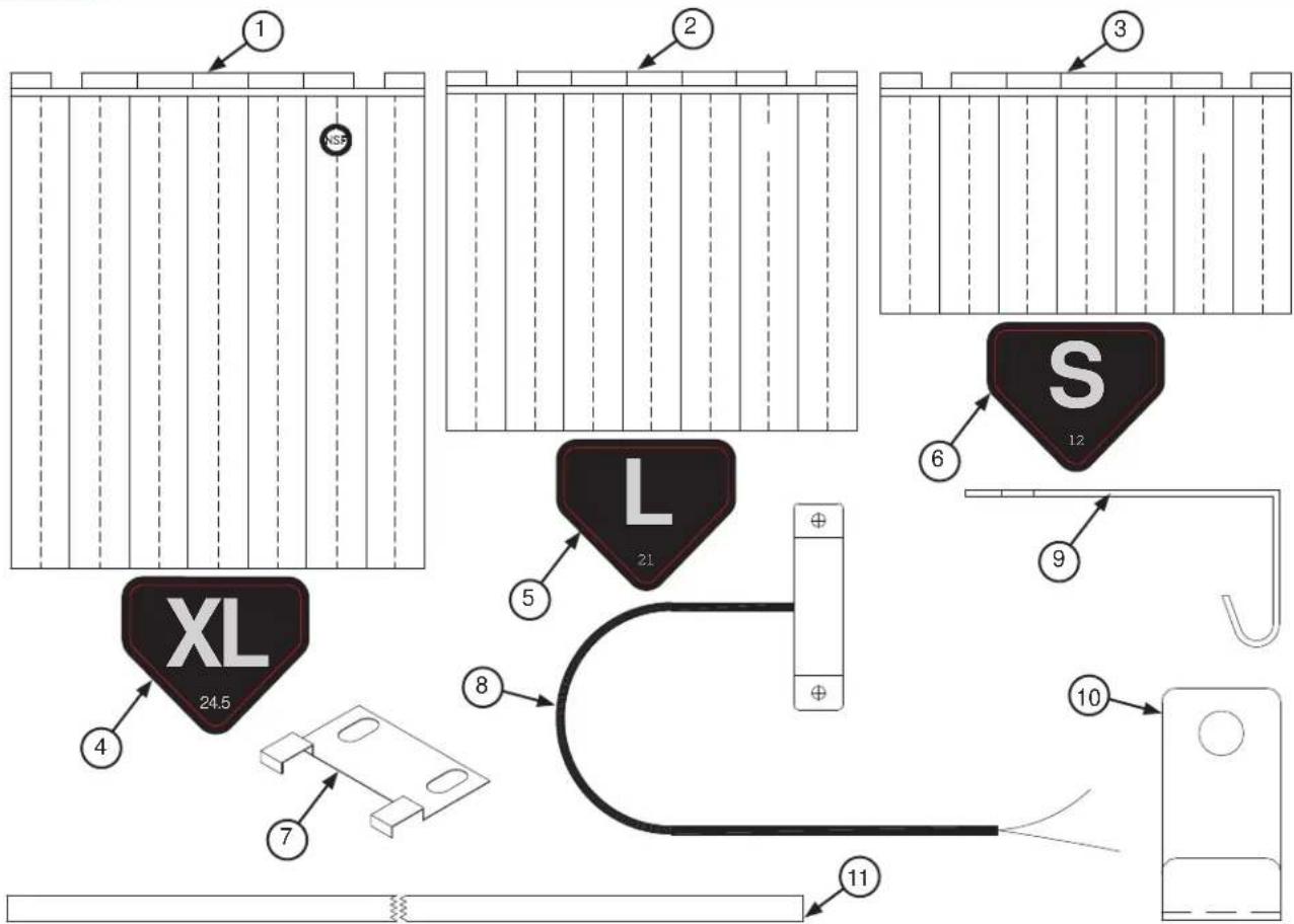
| ITEM QTY | DESCRIPTION | PART NUMBER | |
| 1 1 Curtain, | XL, 24 1/2" x | 20 1/2" 08415-002-47-37 | |
| 2 1 Curtain, | L, 21" x 20 1 | 1/2" 08415-131-73-45 | |
| 3 1 Curtain, | S, 12" x 20 1 | 1/2" 08415-131-73-44 | |
| 4 1 Decal, XL | Curtain 09 | 905-004-38-49 | |
| 5 1 Decal, L | Curtain 099 | 05-004-38-48 | |
| 6 1 Decal, S | Curtain 099 | 05-004-38-46 | |
| 7 1 Limit Switch Bracket | 05700-021-71-18 | ||
| 8 1 Conveyor Switch Replacement Kit | 06401-003-11-79 | ||
| 9 1 Middle Curtain Hook | 05700-011-72-65 | ||
| 10 | 1 Curtain Hook | 05700-011-83-54 | |
| 11 | 1 Curtain Rod | 05700-021-73-43 | |
| 12 | 1 Curtain, XL, Side-loader (Not Shown) | 08415-008-84-88 | |
| 13 | 1 Curtain Rod, Side-loader (Not Shown) | 05700-008-84-57 | |
^1 The Conveyor Switch Replacement Kit contains the switch, a terminal, and a wire nut. Cut the cord on the Conveyor Switch to length in the field and install the terminal there.
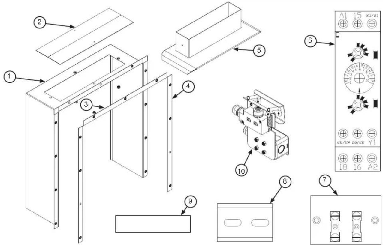
| ITEM QTY | DESCRIPTION | PART NUMBER | |
| 1 | 1 | Vent Cowl (High Hood)Vent Cowl (Low Hood) | 05700-041-86-9405700-002-13-12 |
| 2 | 1 | Vent Cowl CoverVent Cowl Cover Replacement Kit ^1 | 05700-011-74-6706401-003-10-16 |
| 3 1 Gasket, | Top Vent Cowl | 05330-031-83-47 | |
| 4 1 Gasket, | Side Vent Cowl | 05330-031-83-48 | |
| 5 1 Vent Scoop Option | Option | 05700-002-04-08 | |
| 6 1 Delay Timer, | Exhaust | Fan 05945-011-65-44 | |
| 7 1 Terminal Board, | Exhaust | Fan 05940-011-84-41 | |
| 8 1 Din Rail | Exhaust Fan | 05700-002-36-09 | |
| 9 1 Decal, | Exhaust Fan | Load 09905-003-32-20 | |
| 10 | 1 | Striker Plate Limit SwitchStriker Plate Limit Switch Complete Assembly | 05930-002-62-8105700-002-62-94 |
^1 The Vent Cowl Cover Replacement Kit contains the vent cowl cover and hardware.
Exhaust Fan Kit, Electric and Steam Machines
05700-031-90-53
Exhaust Fan Kit, Gas Machines
05700-003-14-59
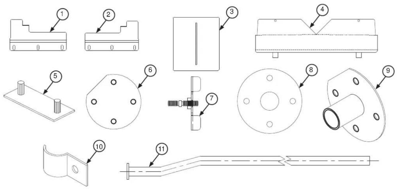
| ITEM QTY | DESCRIPTION | PART NUMBER | |
| 1 1 Plate, Left Water Directional 05700-021-79-27 | |||
| 2 1 Plate, Right Water Directional 05700-021-79-23 | |||
| 3 1 Run-off Sheet 05700-021-71-39 | |||
| 4 1 Splash Shield 05700-031-85-16 | |||
| 5 1 Hole Direction Plate 05700-002-32-50 | |||
| 6 1 Rinse Drain Plate Replacement Kit ^1 | 06401-003-10-07 | ||
| 7 1 Shoulder Bolt Wingnut 05700-002-46-02 | |||
| 8 1 Rinse Drain Plate Gasket 05330-011-72-27 | |||
| 9 1 Rinse Drain Replacement Kit ^2 06401-003-10-05 | |||
| 10 | 1 Pipe Clamp | 05700-000-35-05 | |
| 11 | 1 | Pre-wash Fill Tube (C-66/76/80/90) | 05700-021-74-76 |
| 12 | 1 Vellumoid | Gasket (Not Shown) 05330-111 | 1-42-81 |
Drain Kits contain the parts, gaskets, and hardware.
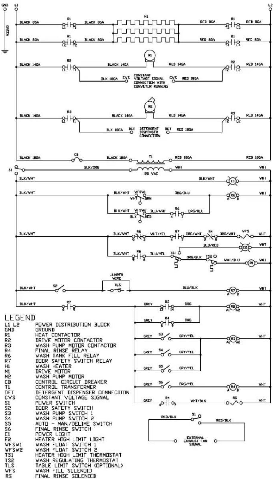
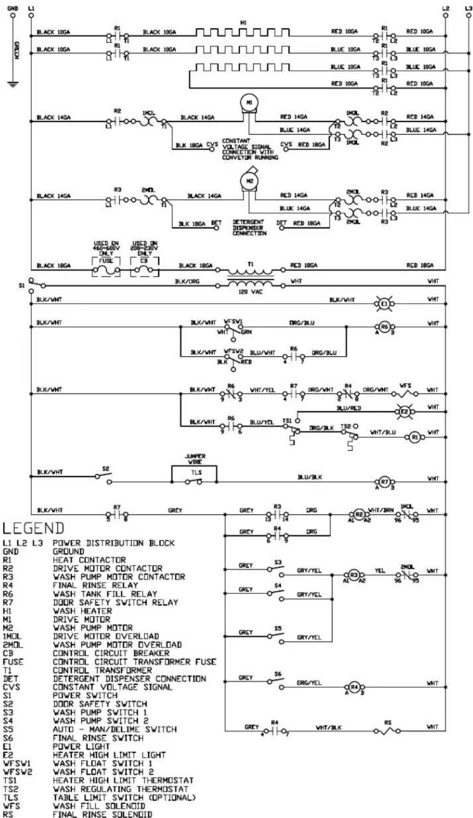
09905-003-60-99 C
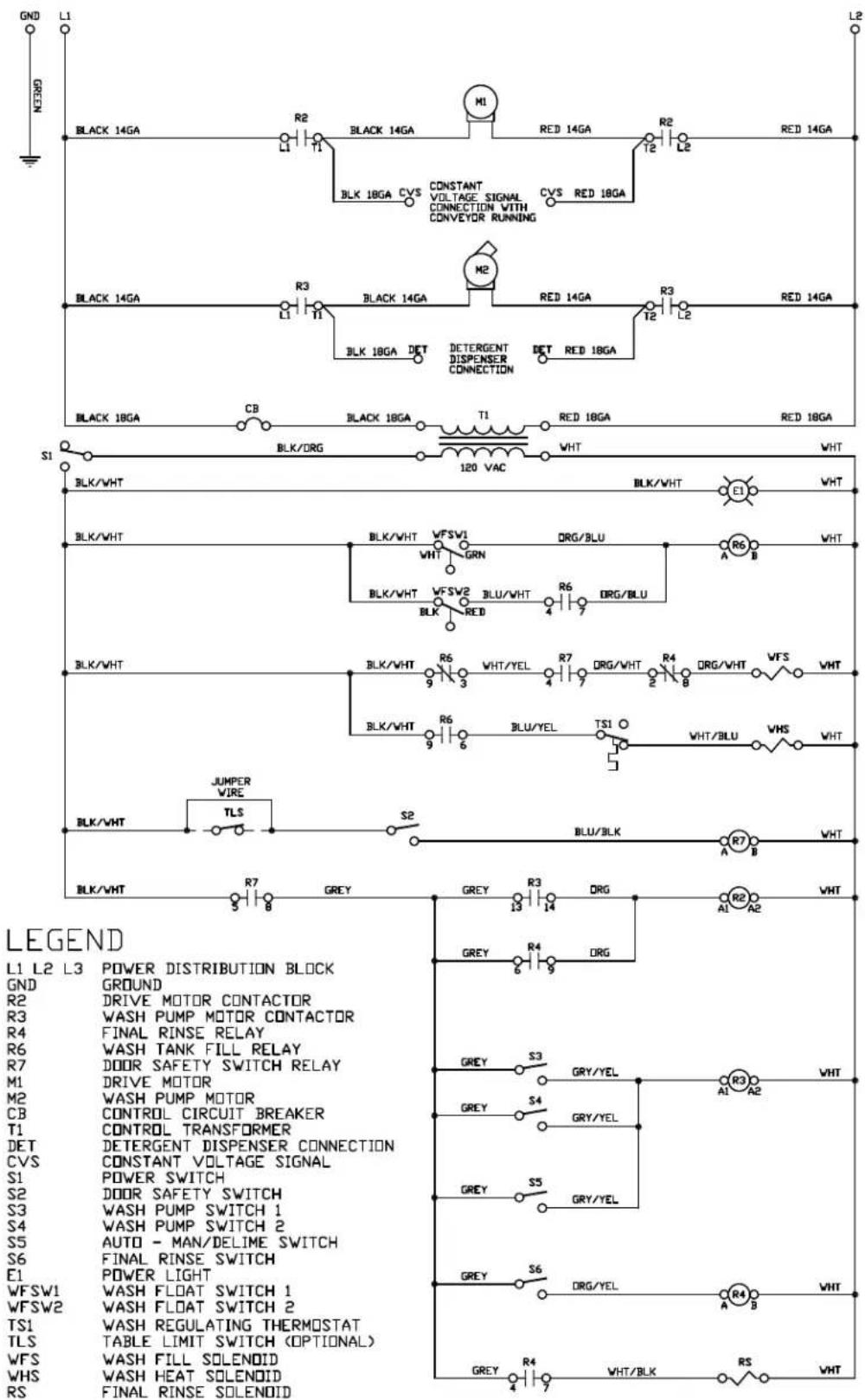
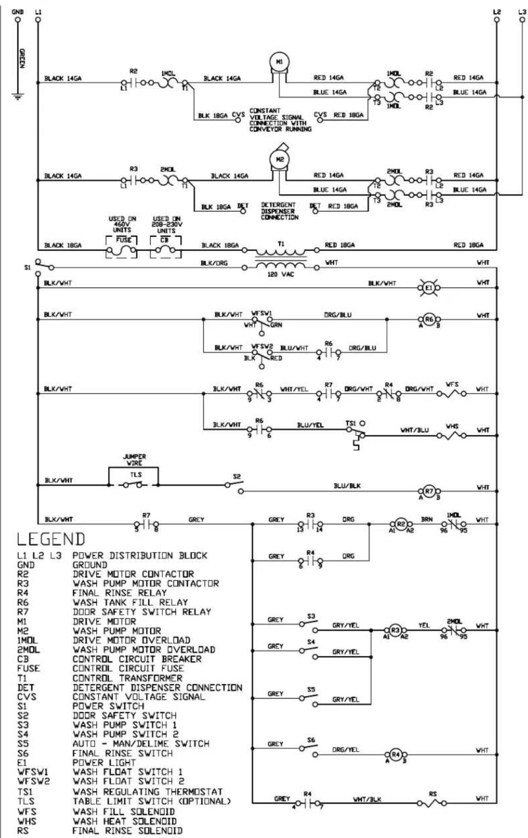
09905-003-61-78
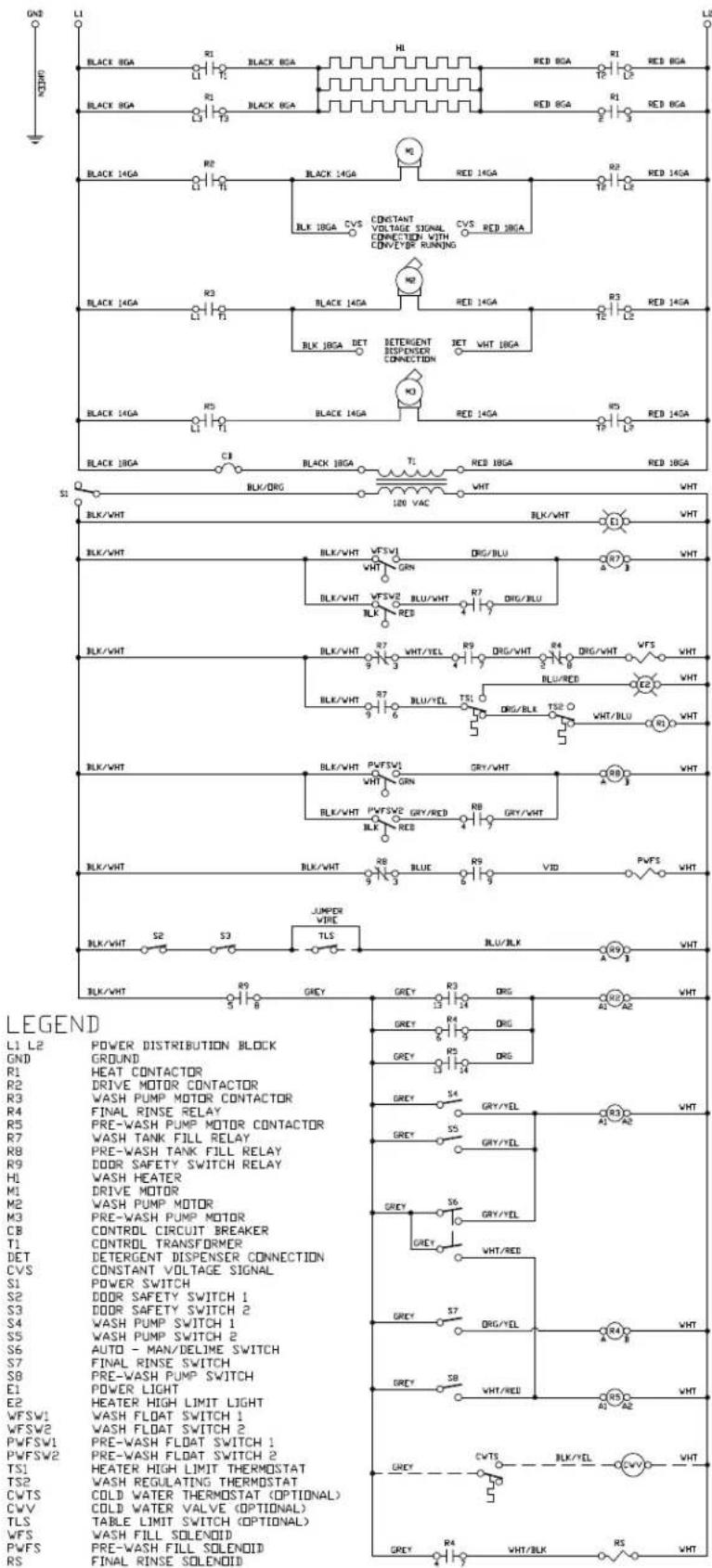
09905-003-65-06
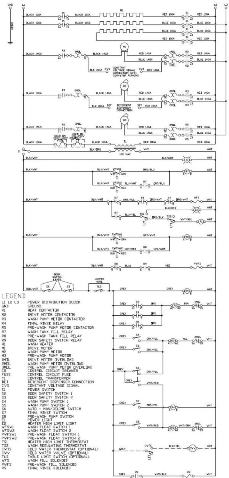
09905-003-65-07
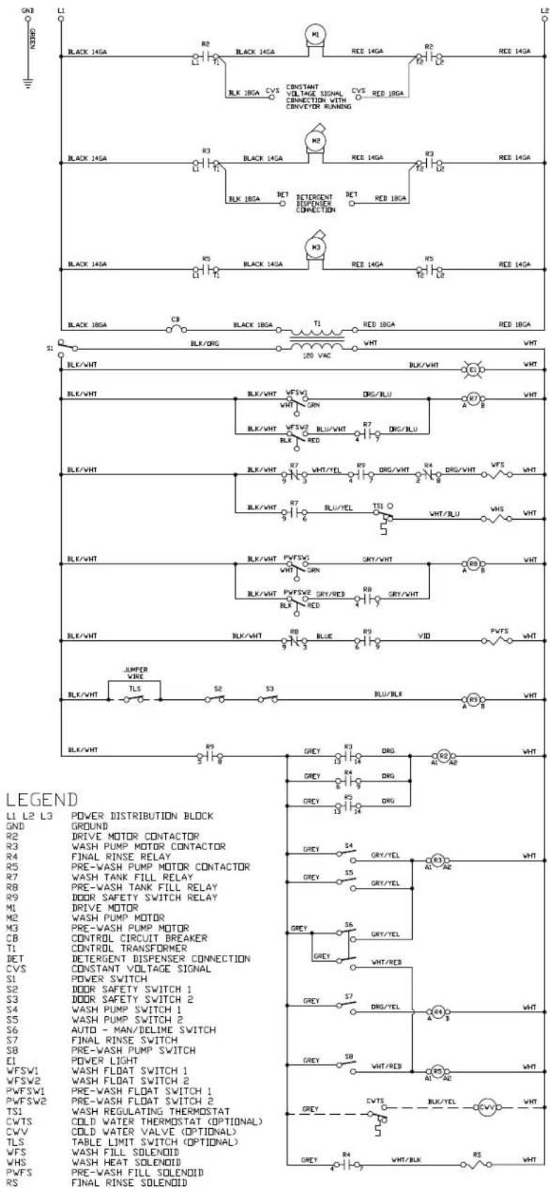
CONVEYOR SIDE LOADER
44, 54, 64 INCH CONVEYORS

ALL CONVEYORS WITH PRE-WASH

DRAIN QUENCH SCHEMATIC
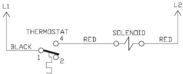
CONNECT BLACK WIRE TO MOTOR CONTACTOR - L1 WITH PIGGYBACK TERMINAL PROVIDED
CONNECT WHITE WIRE TO MOTOR CONTACTOR - L2 WITH PIGGYBACK TERMINAL PROVIDED
CONVEYOR EXHAUST FAN HOOKUP
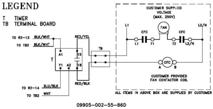
GAS CONVEYOR EXHAUST FAN HOOKUP
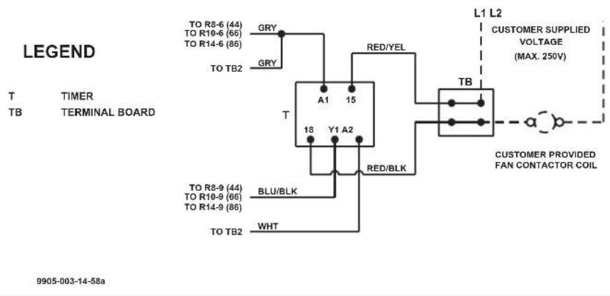
NOBLE RACK CONVEYOR DISHMACHINES

Noble Warewashing • Lancaster, Pennsylvania
www.nobleproducts.biz
For Service Call 1-888-800-5672

- INSTALLATION, OPERATION, AND SERVICE MANUAL
- REVISION HISTORY
- SIDE-LOADER OPTION
- TABLE OF CONTENTS
- GUIDES
- SPECIFICATIONS
- INSTALLATION
- OPERATION
- MAINTENANCE
- TROUBLESHOOTING
- PARTS
- SCHEMATICS
- SYMBOLS
- ABBREVIATIONS & ACRONYMS
- C-44CE LEFT-TO-RIGHT
- MACHINE DIMENSIONS
- C-44CE RIGHT-TO-LEFT
- C-66CE LEFT-TO-RIGHT
- SIDE-LOADER & TABLE INSTALL
- SIDE-LOADER
- Wash
- Ventilation Requirements (CFM)
- Steam Requirements
- Conveyor Speed (FPM)
- Gallons per Rack
- Motor Characteristics
- WATER REQUIREMENTS
- High-temp
- Low-temp
- Available Electrical Characteristics:
- Available Wash Tank Heaters:
- Available Booster Tank Heaters:
- INSTRUCTIONS
- DRAIN LINE
- STEAM LINE CONNECTIONS
- PLUMBING CHECK
- ELECTRICAL POWER CONNECTIONS
- NOTICE
- VENTILATION
- THERMOSTATS
- CHEMICAL FEEDER EQUIPMENT
- CURTAINS
- PREPARATION
- POWER UP
- OPERATING INSTRUCTIONS
- FIRST RACK
- WARE PREPARATION
- WASHING A RACK OF WARE
- OPERATIONAL INSPECTION
- SHUTDOWN
- CLEANING
- DELIMING
- PREVENTATIVE MAINTENANCE
- TORQUE SETTINGS
- DRIVE GEAR REDUCER LUBRICATION
- HEATER SYSTEM TROUBLESHOOTING
- Heater System Check
- Relay Closes
- Relay Does Not Close
- HEATER PROTECTION AND AUTOMATIC FILL (FOR UNITS EQUIPPED WITH AUTOMATIC FILL)
- CONVEYOR SIDE LOADER
- NOBLE RACK CONVEYOR DISHMACHINES
Brand : Noble
Model : Ω
Category : Dishwasher