
NetBackup Flex 5150 - NAS VERITAS - Free user manual and instructions
Find the device manual for free NetBackup Flex 5150 VERITAS in PDF.


| Product Type | Network Attached Storage (NAS) |
| Brand | Veritas |
| Model | NetBackup Flex 5150 |
| Form Factor | 2U Rackmount |
| Drive Bays | 12 x 3.5-inch or 2.5-inch SAS/SATA |
| Max Storage Capacity | Up to 120 TB (with 10 TB drives) |
| Processor | Intel Xeon D-1500 series |
| Memory | 32 GB DDR4 ECC (expandable) |
| Network Interfaces | 4 x 10GbE SFP+ |
| RAID Support | RAID 0, 1, 5, 6, 10, 50, 60 |
| Operating System | Veritas NetBackup Appliance OS |
| Power Supply | Dual redundant 800W |
| Dimensions (W x D x H) | 482 x 650 x 88 mm (19 x 25.6 x 3.5 in) |
| Weight | approx. 25 kg (55 lbs) |
| Power Consumption | 200 W typical, 400 W max |
| Cooling | 3 x hot-swappable fans |
| LED Indicators | Power, status, network, disk activity |
| Management | Web-based GUI, CLI, SNMP |
| Maintenance | Hot-swappable drives, fans, and power supplies |
| Safety | UL, CE, FCC compliant; ESD protection |
| Spare Parts | Contact Veritas support for replacement units |
| General Information | Designed for enterprise backup and disaster recovery |
Frequently Asked Questions - NetBackup Flex 5150 VERITAS
User questions about NetBackup Flex 5150 VERITAS
0 question about this device. Answer the ones you know or ask your own.
Ask a new question about this device
Download the instructions for your NAS in PDF format for free! Find your manual NetBackup Flex 5150 - VERITAS and take your electronic device back in hand. On this page are published all the documents necessary for the use of your device. NetBackup Flex 5150 by VERITAS.
USER MANUAL NetBackup Flex 5150 VERITAS
Veritas 5150 Appliance Hardware Installation Guide
Veritas 5150 Appliance Hardware Installation Guide
Last updated: 2020-04-06
Legal Notice
Copyright © 2020 Veritas Technologies LLC. All rights reserved.
Veritas, the Veritas Logo, and NetBackup are trademarks or registered trademarks of Technologies LLC or its affiliates in the U.S. and other countries. Other names may trademarks of their respective owners.
This product may contain third-party software for which Veritas is required to provide to the third party ("Third-party Programs"). Some of the Third-party Programs are available under open source or free software licenses. The License Agreement accompanying Software does not alter any rights or obligations you may have under those open free software licenses. Refer to the Third-party Legal Notices document accompanying Veritas product or available at:
https://www.veritas.com/about/legal/license-agreements
The product described in this document is distributed under licenses restricting its use, distribution, and decompilation/reverse engineering. No part of this document may be reproduced in any form by any means without prior written authorization of Veritas Te LLC and its licensors, if any.
THE DOCUMENTATION IS PROVIDED "AS IS" AND ALL EXPRESS OR IMPLIED CONDITIONS, REPRESENTATIONS AND WARRANTIES, INCLUDING ANY IMPLIED WARRANTY OF MERCHANTABILITY, FITNESS FOR A PARTICULAR PURPOSE OR NON-INFRINGEMENT, ARE DISCLAIMED, EXCEPT TO THE EXTENT THAT SUCH DISCLAIMERS ARE HELD TO BE LEGALLY INVALID. VERITAS TECHNOLOGIES LLC SHALL NOT BE LIABLE FOR INCIDENTAL OR CONSEQUENTIAL DAMAGES IN CONNECTION WITH THE FURNISHING, PERFORMANCE, OR USE OF THIS DOCUMENTATION. THE INFORMATION CONTAINED IN THIS DOCUMENTATION IS SUBJECT TO CHANGE WITHOUT NOTICE.
The Licensed Software and Documentation are deemed to be commercial computer so as defined in FAR 12.212 and subject to restricted rights as defined in FAR Section "Commercial Computer Software - Restricted Rights" and DFARS 227.7202, et seq. "Commercial Computer Software and Commercial Computer Software Documentation," as applicable, and any successor regulations, whether delivered by Veritas as on premise hosted services. Any use, modification, reproduction release, performance, display or disclose of the Licensed Software and Documentation by the U.S. Government shall be solely accordance with the terms of this Agreement.
Veritas Technologies LLC
2625 Augustine Drive
Santa Clara, CA 95054
http://www.veritas.com
Technical Support
Technical Support maintains support centers globally. All support services will be delivered in accordance with your support agreement and the then-current enterprise technical policies. For information about our support offerings and how to contact Technical Service visit our website:
https://www.veritas.com/support
You can manage your Veritas account information at the following URL:
https://my.veritas.com
If you have questions regarding an existing support agreement, please email the sup agreement administration team for your region as follows:
CustomerCare@veritas.comWorldwide (except Japan)
CustomerCare_Japan@veritas.comJapan
Documentation
Make sure that you have the current version of the documentation. Each document the date of the last update on page 2. The latest documentation is available on t website:
https://www.veritas.com/content/support/en_US/dpp.Appliances.html
Documentation feedback
Your feedback is important to us. Suggest improvements or report errors or omission documentation. Include the document title, document version, chapter title, and section of the text on which you are reporting. Send feedback to:
APPL.docs@veritas.com
You can also see documentation information or ask a question on the Veritas comm http://www.veritas.com/community/
Veritas Services and Operations Readiness Tools (SORT)
Veritas Services and Operations Readiness Tools (SORT) is a website that provides int and tools to automate and simplify certain time-consuming administrative tasks. Depend on the product, SORT helps you prepare for installations and upgrades, identify risks datacenters, and improve operational efficiency. To see what services and tools SORT for your product, see the data sheet:
https://sort.veritas.com/data/support/SORT_Data_Sheet.pdf
Contents
Chapter 1 Hardware overview 5
About the appliance 5
Appliance disk drives 6
Appliance control panel 6
About the Power button LED states 8
About the System Status LED states 9
About the Drive Carrier LED states 12
About the Power Supply LED states 13
Appliance rear panel 14
About IPMI configuration 15
Product documentation 16
Chapter 2 Preinstallation requirements 17
Customer-provided environment and supplies 17
Appliance shipping container contents 18
Electrical and environmental requirements 18
Heat dissipation 18
Prerequisites for the Veritas Remote Management Interface configuration 19
Chapter 3 Installation procedures 21
Installing the appliance into a rack 21
Connecting the network cables 26
Connecting the power cords 26
Turning on the hardware and verifying operation 27
Configuring the Veritas Remote Management Interface 28
Accessing and using the Veritas Remote Management interface 32
Index 36
Hardware overview
This chapter includes the following topics:
■ About the appliance
■ Appliance disk drives
■ Appliance control panel
■ Appliance rear panel
■ About IPMI configuration
■ Product documentation
About the appliance
The Veritas 5150 Appliance is a hardware and software storage system that scale to 14 TB of usable capacity.
Figure 1-1 Veritas 5150 Appliance

The Veritas 5150 Appliance supports the following software: Flex version 1.3 later.
Refer to the Veritas 5150 documentation at the following site for details about storage options.
Appliance Documentation
Appliance disk drives
The front panel of the appliance contains two SSDs and four disk drives.
Figure 1-2 Disk drives

Slot designations are as follows. Do not rearrange the disk drives from the configuration.
Table 1-1 Veritas 5150 Appliance storage devices
| Disk drive roleDeviceRAID cl | |||
| RAID 10,1 | SSD 480GB | Boot/OSIntel 2280 M.2 SATA | |
| RAID 104, 5, 6, 7 | 12G, 7.2K RPM, 3.5" | Internal storageSEAGATE 8TB SA: | |
| N/AN/A | SATA SSD 32GB | CertificateSMART 2280 M.2 |
Appliance control panel
The front panel of the Veritas 5150 Appliance includes a small panel that to the right side of the device. The panel provides basic control of the well as LED status indicators such as the power button, ID button/LED, and status.
Figure 1-3 Control panel system
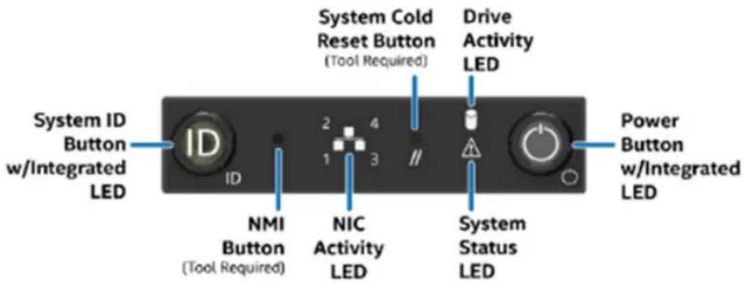
Table 1-2 Control panel system LED descriptions
| System informationLED | |
| Power button with integrated LED | The Power button toggles the system on and off.See “About the Power button LED states” on page 8. |
| Hard drive Activity LED | The drive activity LED on the front panel indicates drive activity from the on-board hard disk controllers. |
| System ID button with integrated LED | Integrated System ID button toggles the integrated ID LED an the blue server board LED on and off.The system ID LED identifies the system for maintenance when it is racked with similar server systems. |
| Network activity LEDs | The front control panel includes one LED for each of t 1 GB RJ45 port on the Quad Gigabit Ethernet OCP module.When network links are detected on the controllers, the LEDs are activated and remain solid green. The LEDs blink when network activity occurs, and the amount of network activity that occurs determines the rate at which they blink. |
| NMI button (recessed, tool required for use) | When it is depressed, the NMI button puts the appliance in a halt state, issues a non-maskable interrupt (NMI), a then triggers the non-maskable interrupt. All server data can be lost.It can only be accessed with a small sharp object such a pin or paperclip.Veritas recommends that you do not enable NMI by pressing the NMI button. |
| System Cold Reset button (recessed, tool required for on non-storage models) | When depressed, the System Cold Reset button restarts and re-initializes the appliance without shutting down gracefully.It can only be accessed with a small sharp object such a pin or paperclip. |
| System Status LED | The System Status LED is bi-color indicator that uses the colors green and amber to display the current health of the appliance.Two locations are provided for you to monitor the health of the system. You can find the first location on the f control panel, while the second location is located on th back edge of the server board. It is viewable from the of the appliance. Both LEDs show the same state of he See “About the System Status LED states” on page 9. |
| Drive Carrier LED | The appliance has 4 internal 3.5" SAS HDD. Each drive carrier has 2 LEDs, a drive activity LED (green) and d status LED (amber).See “About the Drive Carrier LED states” on page 12. |
| Power Supply LED | Each power supply has a bi-color indicator that uses the colors green and amber to represent its current status:See “About the Power Supply LED states” on page 13. |
About the Power button LED states
The Power button is located on the Veritas 5150 Appliance control panel. to turn the appliance on and off.
The following table provides a description of each power state.
Table 1-3 Power button LED states
| DescriptionLEDPower ModeState | |||
| OffNon-ACPIPower | The system power is off, and the BIOS has not initialized the chipset. | ||
| OnNon-ACPIPower | The system power is on and the green Power button LED is active. |
About the System Status LED states
The System Status LED is a bi-color (Green/Amber) indicator that shows the health of the system. The appliance provides two locations for this feature. location is on the Front Control Panel, while the second location is on the of the server board.
Table 1-4 System Status LED states
| DescriptionCriticalityStateColor | |||
| No color | system is not operating. | Not readyOff - | ■The system power is off (AC and/or DC)■ System is in EuP Lot6 Off Mode■ System is in S5 Soft-Off State |
| HealthySolid on | Indicates that the system is running (in S0 State and its status is “Healthy”. The system does not exhibit any errors. AC power is present and BMC has started and manageability functionality is up and running. | ||
| ~1-Hz blinking | DegradedThe system is operating in a degraded state although still functional.orThe system is operating in a redundant state but with an impending failure warning. | System degraded:Redundant loss, such as power supply or fan. Applies only if the associated platform sub-system has redundancy capabilities.Fan warning or failure when the number of fully operational fans is more than minimum number needed to cool the system.Non-critical threshold crossed: Temperature (including HSBP temp), voltage, input power to power supply, output current for main power rail from power supply and Processor Thermal Control (Therm Ctrl) sensors.Power supply predictive failure occurred while redundant power supply configuration was present.Unable to use all of the installed memory (more than one DIMM is installed).Correctable errors over a threshold and migrating to a spare DIMM (memory sparing). This indicates that the system has no spared DIMMs (a redundancy lost condition). The corresponding DIMM LED also lights up. | |
| ~1-Hz blinking | DegradedThe system is operating in a degraded state although still functional.orThe system is operating in a redundant state but with an impending failure warning. | System degraded: (continued)In mirrored configuration, when memory mirroring takes place and system loses memory redundancy.Battery failureBMC executing in uBoot. (Indicated by Chassis ID blinking at 3Hz). System in degraded state (no manageability). BMC uBoot is running but has not transferred control to the BMC Linux. Server will be in this state 6-8 seconds after BMC reset while it pulls the Linux image into flash.BMC booting Linux. (Indicated by Chassis ID solid ON). System in degraded state (no manageability). Control has been passed from BMC uBoot to BMC Linux itself. It will be in this state for 10-20 seconds.BMC Watchdog has reset the BMC.Power unit sensor offset for configuration error is asserted.Hard disk drive HSC is offline or degraded. | |
| ~1-Hz blinking | Non-criticalThe system is operating in a degraded state with an impending failure warning.However, the system is still functioning. | Non-fatal, although the system is likely to fail due to the following issues:Critical threshold crossed - Voltage, temperature (including HSBP temp), input power to power supply, output current for main power rail from power supply and PROCHOT (Therm Ctrl) sensors.VRD Hot assertedMinimum number of fans to cool the system not present or failedHard drive faultPower Unit Redundancy sensor - Insufficient resources offset (indicates not enough power supplies present)Correctable memory error threshold has been reached when the system is operating in a non-sparing and non-mirroring mode. | |
| Solid onAmbe | Critical, non-recoverable - System is halted | Fatal alarm - system has failed or shutdown:CPU CATERR signal assertedMSID mismatch detected (CATERR also asserts for this case)CPU1 is missingCPU Thermal TripNo power - power faultDIMM failure when there is only one DIMM present; no other good DIMM memory presentRun time memory uncorrectable error in non-redundant mode.DIMM Thermal Trip or equivalentSBB Thermal Trip or equivalentCPU ERR2 signal is assertedBMC/Video memory test failed (Chassis ID shows blue/solid-on for this condition)Both uBoot BMC FW images are bad (Chassis ID shows blue/solid-on for this condition)240 VA faultFatal error in processor initialization:Processor family not identicalProcessor model not identicalProcessor core/thread counts not identicalProcessor cache size not identicalUnable to synchronize processor frequencyUnable to synchronize QPI link frequencyUncorrectable memory error in non-redundant mode |
About the Drive Carrier LED states
Each drive carrier has 2 LEDs, a drive activity LED which is green in c drive status LED which is amber in color.
The following tables provide a description of the drive carrier LEDs.
Table 1-5 Amber LED status
| Drive statusLED state | |
| Hard drive faultSolid On (SO) | |
| No access and no faultOff | |
| RAID rebuild in progress1-Hz blinking | |
| Locate (identify)2-Hz blinking |
Table 1-6 Green LED status
| LED stateCondition | |
| Solid On (SO)Power on with no drive ac | |
| Power on with drive activity | Blinks off when processing a command |
| OffPower on and drive spun down | |
| BlinksPower on with drive spinning up |
About the Power Supply LED states
The power supply module has a bi-color LED to represent the current sta power supply.
The following table provides a description of each power supply state.
Table 1-7 Power supply LED states
| Power supply conditionLED | |
| Output on and okSolid green | |
| No AC power to all power suppliesOff | |
| 1-Hz blinking (green) | AC is present but only 12 VSB or is in redundant state |
| Solid amber | ■ AC cord is unplugged or AC power is lost but a second power supply with AC input power is present■ Power supply critical event is causing a shutdown such as a failure, OCP, OVP or fan fail |
| 1-Hz blinking (amber) | Power supply warning events (such as, high temperature, high power, high current or slow fan) but the power supply continues to operate |
| Power supply FW updating2-Hz blinking (gree |
Both the SSDs also have a bi-color LED to represent the current status (supply.
The following table provides a description of the SSD LED states.
Table 1-8 SSD LED states
| Power supply conditionLED | |
| SSD is receiving powerSolid green | |
| No power to the SSDOff | |
| Drive activities to the SSD are on-goingBlink |
Appliance rear panel
The rear panel of the appliance contains several default ports that are em
Figure 1-4 Rear panel

The following list describes the numbered ports.
- VGA port
- 3 USB ports
-
Veritas Remote Management Interface (remote management (IPMI) port)
-
Four copper, RJ45, 1Gb Ethernet* ports, host0, NIC0, NIC1, and NIC2, right
-
The middle slot is used for the external SAS tape-out functionality. This will be implemented in a future release.
-
The right PCIe is used for the add-on ethernet cards
Note: * The embedded Ethernet ports are copper. PCIe Ethernet ports can fibre or copper. You cannot bond the copper ports and the fibre ports to
About IPMI configuration
The Intelligent Platform Management Interface (or IPMI) provides management monitoring capabilities independently of the host system's CPU, firmware, and operating system. You can configure the IPMI sub-system for your appliance can use the remote management port, located on the rear panel of the a to connect to the IPMI sub-system.
The following figure shows the remote management port (or the IPMI port) rear panel of the appliance:

natural_image
Back view of a server rack with ports, connectors, and ventilation fans (no readable text or symbols)The IPMI is beneficial after an unexpected power outage shuts down the system. In case the appliance is not accessible after the power is restored use a laptop or desktop computer to access the appliance remotely by us network connection to the hardware rather than to an operating system or shell. This enables you to control and monitor the appliance even if it is down, unresponsive, or without any operating system.
The following diagram illustrates how IPMI works:

flowchart
graph TD
    A["Remote Management Port"] --> B{When an appliance is powered off or cannot be accessed using the network interface}
    B --> C["Network Interface"]
    C --> D["Remote Management Console"]
    style A fill:#f9f,stroke:#333
    style B fill:#ccf,stroke:#333
    style C fill:#cfc,stroke:#333
    style D fill:#fcc,stroke:#333
The following are some of the main uses of IPMI:
■ Manage an appliance that is powered off or unresponsive. Using the IPM can power on, power off, or restart the appliance from a remote location
■ Provide out-of-band management and help manage situations where local physical access to the appliance is not possible or preferred like branch and remote data centers.
■ Access the appliance shell remotely using IPMI if regular network interface not possible.
Note: Only the appliance menu can be accessed by using the IPMI in The web console cannot be accessed by using the IPMI interface.
■ Reimage the appliance from the IPMI interface by using ISO redirection.
■ Monitor hardware health of the appliance from a remote location.
- Avoid messy cabling and hardware like keyboard, monitor, and mouse (K' solutions to access the appliance.
See "Configuring the Veritas Remote Management Interface" on page 28.
Product documentation
Additional documentation is available at the following site:
Appliance Documentation
Preinstallation requirements
This chapter includes the following topics:
■ Customer-provided environment and supplies
■ Appliance shipping container contents
■ Electrical and environmental requirements
■ Heat dissipation
■ Prerequisites for the Veritas Remote Management Interface configuration
Customer-provided environment and supplies
For best ventilation, the rack cabinet:
■ Should be at least 100 cm (4 feet) from walls.
- Should have at least 100 cm (4 feet) from other cabinets on the front of the appliance.
Data centers with two-foot spaces in the front and in the back of the a, acceptable with proper cooling and ventilation.
Refer to the following section for more details.
See “Heat dissipation” on page 18.
The following describes the necessary personnel and equipment that are needed at the installation site:
■ At least one person or a mechanical lift to move the appliance.
- Optional: For SAS tape-out capability only. A SAS cable with at least o connector. The second connector can be SAS-2 or SAS-3 depending on type of tape-out device the customer uses.
■ A USB-keyboard and a monitor to connect to the appliance.
■ A 19-inch rack with dual Power Distribution Units (PDUs) with 120VAC of 220VAC power supplies.
Appliance shipping container contents
The following items ship within the appliance box.
■ Open Me First container, containing:
■ Cabling and remote management configuration card
■ Warranty and license information
■ Safety/Compliance flyer
■ Rail installation card
■ Two power cables
- Bezel
Electrical and environmental requirements
This section lists the electrical and environmental specifications for the Verita Appliance.
Electrical requirements:
■ 100 - 127 V, 10A (2 power cords) at 50/60 Hz
■ 200 - 240 V, 5A (2 power cords) at 50/60 Hz
Environmental requirements:
■ 10°C to 35°C (50°F to 95°F)
Heat dissipation
Air flows from the front of each unit and exits from the rear of each u install the optional bezel without disruption to the airflow.
For best ventilation, the rack cabinet (if installed) should:
■ Be at least 100 cm (4 feet) from walls.
- Be at least 100 cm (4 feet) from other cabinets on the front and back appliance.
Note: Data centers with two-foot spaces in the front and in the back of t are acceptable with proper cooling and ventilation.
Veritas provides the following requirements to ensure sufficient cooling.
■ Veritas requires that you install the system in a National Engineering Manufacturer's Association (NEMA)-certified or equivalent rack.
- A minimum of 3 inches (7.6 cm) of space must be between the front appliance and the cabinet door or other air block.
- A minimum of 6 inches (15.2 cm) of space must be between the rear appliance and the cabinet rear or other air block.
Refer to the Veritas 5150 Appliance Product Description Guide for specifications about temperature and cooling.
Appliance documentation
Prerequisites for the Veritas Remote Managem Interface configuration
Verify the following configuration prerequisites:
■ The remote management (IPMI) port auto-negotiates its link speed to 1
Note: If the Veritas Remote Management Interface port is connected to managed switch port, it is recommended that you configure the switch p auto-negotiation
If a firewall exists between the appliance and the remote devices that are an appliance (like a laptop computer), open the following ports:
SOL SSH66
HTTP80
SNMP162
HTTPS443
Floppy/USB media623
Secured Floppy/USB media627
CD5120
Secured CD5124
KVM5900
Secured KVM5902
Note: If you have a private internal network, remember to configure the accordingly in your network address translation (NAT).
- The remote management (IPMI) port must be configured as a DHCP or address.
Installation procedures
This chapter includes the following topics:
■ Installing the appliance into a rack
■ Connecting the network cables
■ Connecting the power cords
■ Turning on the hardware and verifying operation
■ Configuring the Veritas Remote Management Interface
■ Accessing and using the Veritas Remote Management interface
Installing the appliance into a rack
Veritas recommends the following:
■ Two people should install the rails; one person at the back of the rack at the front.
■ Two people should lift and place the appliance into the mounted rails.
To install the appliance into the rack
1 Extend both of the rails until they lock in place.

natural_image
Person installing or adjusting a metal shelf panel in a storage room (no visible text or symbols)2 While standing in front of the chassis, position the appliance within the rails with the back of the chassis towards the rack. Raise the front of and align the rear mounting posts of the chassis with the rear rail c) both rails.

natural_image
Person assembling a metal-framed rack system, no visible text or symbols3 Lower the rear chassis mounting posts into the rear rail cut-outs.

natural_image
Close-up of a metallic metal bracket with grid pattern and mounting holes, no visible text or symbols4 When the rear chassis mounting posts are secured in the rail cut-outs, the front of the chassis down until the front chassis mounting posts o side of the chassis fit securely into the front rail cut-outs on each ra

natural_image
Person handling a server rack with a label, no visible text or symbols on the rack or background5 Check the front rail locks on each of the rails and confirm that they
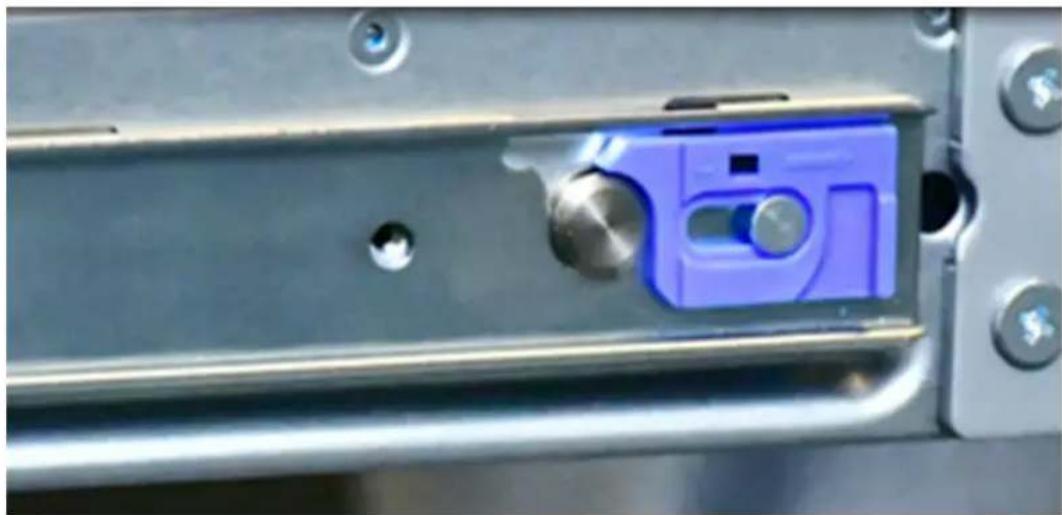
natural_image
Close-up of a blue plastic mechanical component mounted on a metal frame, with no visible text or symbols.6 Lift the release tabs located at the sides of the rails and push the into the rack as far as possible.

7 Fasten the front of the appliance to the rack with the two captive fas are attached to the front of the chassis.

natural_image
Close-up of a computer tower with a hand inserting a screwdriver into the rack (no visible text or symbols)Connecting the network cables
The networking ports are accessed on the rear panel of the device. The management (IPMI) port is for use by Veritas Technical Support staff or by field service technicians. The following picture shows the layout of the networks. It includes the four 1 Gb Ethernet ports. The Veritas Remote Manager Interface port is located to the left of the 1 Gb Ethernet ports.
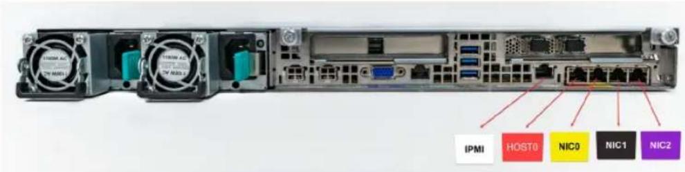
Before configuration, host0 needs to be connected to an administrative network that does not provide any backup data transfer.
For configuration, host0 is required for the platform setup and at least one should be configured for the application instance.
Note: You cannot bond the copper 1 GbE port that are installed in the chassis with fibre ports on PCIe 10-GbE cards.
See "Connecting the power cords" on page 26.
Connecting the power cords
Each appliance contains two AC power supplies. To ensure power redundant connect the power supplies on each component to separate AC power sou
Caution: Do not turn on the power to any components while connecting t cords. The components must be turned on in a specific sequence to ensu communication.
To connect the power cables
1 Verify that the AC power supply input for the appliance is within one ranges.
■ 100 - 127 VAC at 50/60 Hz
■ 200 - 240 VAC at 50/60 Hz
2 For each device, obtain two power cords that are appropriate for your and equipment.
3 Connect one cable to one PDU strip.
4 Connect the other cable to the other PDU strip.
See "Turning on the hardware and verifying operation" on page 27.
Turning on the hardware and verifying opera
To turn on the appliance
1 On the front, right, side of the appliance press the Power button.

natural_image
Close-up of a black electronic device rear panel showing ports, connectors, and a red circular button labeled 'ID' (no readable text or symbols beyond basic labels)2 Verify that the bottom LED in all the four disk drive slots are green.

natural_image
Front view of a server rack with four green indicator lights and red circular annotations (no readable text or symbols)The following table provides details of the disk drive LEDs.
DescriptionStatesLED
1-Status LED, Off
No fault
Top
Solid amber
Disk fault
Blinking amber
A RAID rebuild is in progress
2-Activity LED, Off
Power is on and the disk has spun down
Bottom
Solid green
Power is on but there is no disk activity
Blinking green
Power is on and the disk is spinning up
Blinks green occasionally
Commands are being processed
3 On the bottom, left, rear of the appliance verify that the LED on each supply is green.
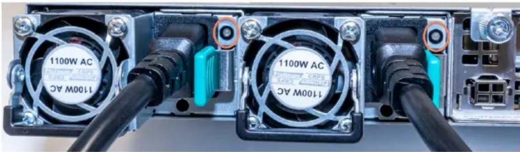
natural_image
Close-up of a computer power supply unit rear panel with two 1100W AC fans and connected cables (no visible text or symbols beyond labels)4 Proceed to the next section to configure remote management.
Configuring the Veritas Remote Management Interface
Veritas Flex Appliance release 1.x does not support configuring the IPMI port the Flex Appliance Shell.
To configure the dedicated Veritas Remote Management Interface (IPMI) settings in the BIOS
1 Connect a standard video cable between the VGA (Video Graphics Arra and the computer monitor
2 Connect a keyboard to a USB port at the rear of the Flex 5150 ap
3 Ensure that the power cords are connected to a power supply and pr power switch on the front panel.
4 The prompt about accessing the BIOS at the beginning of the startup appears. Wait until the Veritas logo shows up and press F2 to enter BIOS setup screen. The initial setup dialog box appears and prompts

Warning: When you are in the BIOS, do not perform any other steps than the ones mentioned in this section.
Note: If you miss the initial setup dialog box prompt in step 4, the appliance shell appears. Shut down and restart the appliance and try accessing 1 menu again.
The Setup Menu page appears and the Main menu option should be highlighted.

5 Use the down key on the keyboard and navigate to the Server Mana menu option. Press Enter.
6 Press the up or down key on the keyboard to navigate to BMC LAN Configuration. Press Enter.
7 The BMC LAN Configuration options screen appears.

8 Navigate to the Dedicated Management LAN Configuration option. Use information supplied by the customer to fill in the following fields: IP & IP address, Subnet mask, Gateway IP.

9 To save your BIOS changes, press F10.

10 Press Y to save and exit. The appliance restarts itself.
Accessing and using the Veritas Remote Management interface
The IPMI web interface is known as Veritas Remote Management interface. can use Veritas Remote Management interface to log on to the appliance
Before you use the remote management interface, the following prerequisites be met:
■ The Remote Management interface (IPMI port) must first be configured.
■ At least one power cable must be connected to a functioning power so
■ At least one user must be enabled to use the LAN channel(s).
Note: A default user is configured in the system. The default user name sysadmin. The default password is P@ssw0rd, where 0 is the number zero.
To access and use the Veritas Remote Management web interface from remote computer
1 Log on to a remote computer in the network and open a supported browser.
2 Enter the remote management (IPMI) port IP address (https://) that is a to the remote management port. The following page appears:

3 Enter your login credentials. The default user name is sysadmin. The password is P@ssw0rd, where 0 is the number zero.
Click Login.
4 Click the Remote Control section located at the top of the page. The Remote Control section lets you remotely monitor and control the server.
Do one of the following to launch the Flex Appliance Shell:
■ If available, navigate to Remote Control> iKVM over HTML5.
Click Launch iKVM over HTML5 to launch the Appliance shell. A window opens that enables you to remotely monitor and control the appliance.

Note: Availability of the HTML5 option depends on the appliance firm version. You can check the version from the System> System Information page. The BIOS must show version 00.01.0016 or later.
- Click Remote Control > KVM/Console Redirection . Click Launch Console to launch the appliance shell menu.

Remote Control
This section allows you to remotely monitor and control the server.
Console Redirection
Console Redirection
Server Power Control
Virtual Front Panel
Console redirection creates a virtual display and redirects your keyboard and mouse to the virtual display. Additional local resources can also be redirected for use on the remote system. The virtual display allows remote administration of your server. Press the Launch Console button to start the virtual console and administer your server remotely.
A Remote Management Module (RMM) must be installed in the remote system's motherboard to enable Console Redirection
Launch Console
A JViewer application opens that enables you to remotely monitor and control the appliance. This application requires Java Runtime Environment (JRE) version 6.0 or later. Install Java. You can login to the JView application using the same user name and password from step 3
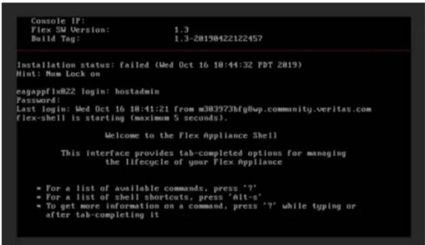
5 You can now access and log on to the appliance shell. Enter the us and password for the appliance.
By default, the user name hostadmin has the password, P@ssw0rd where 0 is the number zero.
Type "?" and then enter the "system" command to actually see the list available commands.
A
airflow 18
appliance
about 5
cabling
network ports 26
power cords 26
disk drive slots 6
eth0/NIC1 IP address 26
ethernet ports, bonding 26
installing into rack 21
LEDs
control panel 6
disk drives 27
drive carrier 12
power button 8
power supplies 28
power supply 13
system status 9
rear panel 14
shipping contents 18
turning on hardware 27
B
best practices
heat dissipation 18
D
documentation 16
H
heat dissipation 18
|
IP address
eth0/NIC1 port 26
IPMI configuration
about 15
0
Open Me First container
appliance 18
P
prerequisites
Veritas Remote Management Interface configuration 19
R
rack cabinet requirements 17
V
Veritas Remote Management Interface configuration 28
Veritas Remote Management interface accessing 32


- Veritas 5150 Appliance Hardware Installation Guide
- Legal Notice
- Technical Support
- Documentation
- Documentation feedback
- Veritas Services and Operations Readiness Tools (SORT)
- Contents
- Chapter 1 Hardware overview 5
- Chapter 2 Preinstallation requirements 17
- Chapter 3 Installation procedures 21
- Index 36
- Hardware overview
- About the appliance
- Appliance disk drives
- Appliance control panel
- About the Power button LED states
- About the System Status LED states
- About the Drive Carrier LED states
- About the Power Supply LED states
- Appliance rear panel
- About IPMI configuration
- Product documentation
- Preinstallation requirements
- Customer-provided environment and supplies
- Appliance shipping container contents
- Electrical and environmental requirements
- Heat dissipation
- Prerequisites for the Veritas Remote Managem Interface configuration
- Installation procedures
- Installing the appliance into a rack
- To install the appliance into the rack
- Connecting the network cables
- Connecting the power cords
- To connect the power cables
- Turning on the hardware and verifying opera
- To turn on the appliance
- DescriptionStatesLED
- Configuring the Veritas Remote Management Interface
- Accessing and using the Veritas Remote Management interface
- To access and use the Veritas Remote Management web interface from remote computer
- Console Redirection
- A
- B
- D
- H
- |
- 0
- P
- R
- V
Brand : VERITAS
Model : NetBackup Flex 5150
Category : NAS