
MultiDO 5500D - Measuring instrument YSI - Free user manual and instructions
Find the device manual for free MultiDO 5500D YSI in PDF.


| Product Type | Aquatic monitor, control, and alarm instrument |
| Model | MultiDO 5500D (5500D-01, 5500D-02, 5500D-04) |
| Power Supply (AC Version) | 100-240 VAC, 50-60 Hz, 300 mA |
| Power Supply (DC Version) | 9-16.5 VDC, 800 mA |
| Backup Power | 12 VDC battery (user supplied) |
| Display | Backlit graphic LCD (320x240), continuously displays system conditions |
| DO Inputs | Up to 4 independent dissolved oxygen sensors (optical for 5500D, galvanic for 5400) |
| Aux Inputs | 6 independent: digital (dry contact) or analog (0-1 VDC, 0-5 VDC, 4-20 mA); 4 can be temperature (10K thermistor) |
| E-Aux Inputs | 8 inputs via optional IOEM module |
| Relay Outputs | 8 onboard relays, SPDT, 240 VAC @ 5 A, 110 VAC @ 10 A |
| Communication | RS232 (local up to 100 ft), RS485 network (up to 32 instruments, 4000 ft), optional Ethernet (TCP/IP) for email alarming and remote access |
| Data Logging | Non-volatile: 2000 sensor records, 1250 event records, 500 calibration records, 1000 configuration records |
| Timers | 4 daily timers (10 events each), 4 Feed Smart timers with sensor control |
| Environmental Rating | NEMA 4X, IP65 (enclosure); IP68/NEMA 6 (compression fittings) |
| Operating Temperature | -15 to 70 °C (5 to 158 °F) |
| Enclosure Material | NEMA 4X rated, suitable for outdoor exposure |
| Mounting Options | Surface, rail (1-1.5 in pipe), panel (cutout 9.5" x 7.5"), weather shield available |
| Calibration | DO % saturation and mg/L via front panel; temperature periodic check |
| Maintenance | Regular probe cleaning, membrane/sensor cap replacement, desiccant replacement, calibration verification |
| Safety | Warnings: disconnect power before wiring; qualified electrician for mains; observe ESD precautions |
| Warranty | Instrument: 2 years; cables, probes, sensors: 1 year |
| Accessories | Weather shield, panel mount kit, rail mount kit, serial-to-Ethernet device, AquaManager PC software, spare desiccant packs |
Frequently Asked Questions - MultiDO 5500D YSI
User questions about MultiDO 5500D YSI
0 question about this device. Answer the ones you know or ask your own.
Ask a new question about this device
Download the instructions for your Measuring instrument in PDF format for free! Find your manual MultiDO 5500D - YSI and take your electronic device back in hand. On this page are published all the documents necessary for the use of your device. MultiDO 5500D by YSI.
USER MANUAL MultiDO 5500D YSI
Monitor, Control, & Alarm Instruments
User Manual
Table of Contents
1 Introduction....9
Introduction....10
Product Description 11
Preview of User Manual....12
Product Specifications 13
Environmental Specifications....14
Input System Specifications....14
Component and System (non input) Specifications....16
2 Safety....19
THIS IS IMPORTANT ....20
Warnings and Cautions....20
Warnings 21
Cautions 23
3 Installation & Wiring 25
Hardware Installation....26
Step 1 Install 5X00....27
Location Considerations....27
Mount the 5X00....28
Surface Mount 28
Rail Mount 29
Panel Mount 29
Install the Weather Shield....33
Step 2 Locate and Install Sensor(s)....34
Location Considerations....35
YSI 5420 and YSI 5421 (Galvanic) probe assemblies ....37
YSI 626250 ODO (Optical Dissolved Oxygen) sensor....37
Install Temperature Sensors....38
Wiring Information....39
PCBs 39
5X00 Bulkhead Fittings 40
Accessing the I/O Board 40
Open Front Panel to Access I/O Board 41
Close Front Panel....41
Control Board 42
Step 3 Ground 5X00 43
Directions to Ground 5X00....44
Step 4 Wire Power....45
Wire AC Power 45
Item # 605877
Rev F
Drawing # A605877
May 2015
Copyright
©2015 YSI Incorporated.
Manufacturer:
YSI, Incorporated
A Xylem Brand
1700/1725 Brannum Lane
Yellow Springs, OH 45387 USA
937-767-7241 www.ysi.com
All trademarks herein are
registered to YSI Incorporated
unless otherwise noted.
Teflon is a trademark of DuPont.
Microsoft and Windows are registered trademarks of the Microsoft
Corporation in the United States and other countries.
Pentium is a registered trademark of Intel Corporation.
Table of Contents
Directions to Wire AC Power 45
Wire DC Power and Backup Power 46
Directions to Wire DC Power/DC Backup Power ....47
Step 5 Wire Sensor(s)....49
Wire DO Sensors 49
Directions to Wire DO Sensor(s)....49
Wire Temperature Sensor(s) 52
Directions to Wire Temperature Sensor(s) 53
Step 6 Wire Relay outputs ....54
Directions to Wire Relay Outputs ....54
Wiring a Contactor 55
Step 7 Wire Aux Inputs (Non Temperature) 56
Directions to Wire Aux Inputs (Non Temperature Inputs)......57
Step 8 Wire Network....60
Directions to Wire Network....61
Step 9 Wire and Install Communication Equipment....66
Email Alarming 66
RS232 Communication 66
Ethernet (TCP/IP) Module Communication....68
Step 10 Install and Wire IOEM/REM instruments....68
Lightning and Surge Protection....68
Sealants, Desiccants, and Securing 5X00....69
4 Configuring 5X00 Systems 71
5X00 Configuration and Monitoring 72
Front Panel Keys 73
Softkeys 73
Run Screen 75
Run Screen Icons....76
Menus 78
Submenu Screen Types....80
Main Menu 81
Calibration Menu....81
Getting Ready to Calibrate....82
Calibration Log 83
DO....83
Directions to Calibrate DO Sensor %Sat....83
Directions to Calibrate DO Sensor mg/L 84
Local vs Remote Instruments 86
System Menu 86
Adjust Contrast....87
Buzzer 88
BackLighting Timer....89
Table of Contents
Communication 89
Email Alarming....90
Ethernet....92
Node Network....97
Send Test Email Msg....99
Email Retry Delay....100
Force Serial Port....101
Non-Networked (Stand Alone) 5X00s ....101
Configure AUX 102
Probe Name 102
Input Type 103
Configure E-AUX....108
Probe Name 109
Instrument....110
Channel 111
Input Type....111
Data Logging....117
Data Logging 118
Event Logging 120
Date/Time 122
Display Settings 123
ODO Cal K (5500D-01, 5500D-02 and 5500D-04)....124
Downloader/Updating 5X00 Firmware 126
Firmware Updater Directions....127
Force Downloader 130
General Alarm 131
Alarm Hold Off 132
Relay 132
Name Devices/Sensors....134
Password 137
Power Fail Menu 138
Serial Number 139
Service 140
Reset Clean Probes 140
Reset To Factory 141
Output Test 144
Service Hold 147
Version 148
AquaManager and the System Menu 149
Sensor Setup 150
Control Mode....152
Set Point Control 153
Timed versus Normal (non timed) Control....157
Table of Contents
Validation Error and Autofix - Set Point Control Only .....157
PID/PWM and PID 4/20mA Control mode....159
Aux and E-Aux Relay Digital 164
Aux and E-Aux Analog (0-1VDC, 0-5VDC and 4/20mA).....166
Temperature 168
DO 1-4....173
Salinity & Temp Compensation for DO Measurements .....173
Two Range Controls for DO 173
Configure DO Systems....174
E-Aux system Offline 177
Configure sensor system as a 4/20mA output....178
AquaManager and the Sensor Setup Menu....179
Timers 180
Timers 1-4 180
Directions to Configure Timers 1 - 4....180
Feed Smart ^™ Timers 1-4....182
Feed Mode 184
Daily Weight 185
Daily Feedings 185
FCR 186
Sensors 187
Calibrate 189
AquaManager and the Timer Menu....190
Control Menu 192
Msg's Menu....193
Calibration Logs 194
Event Logs 194
Sensor Logs 195
Svr Hold softkey Button 196
5 AquaManager....197
Installing AquaManager 198
PC requirements and features....198
Software Installation....199
AquaManager Windows....200
Explorer Window 200
Node (Graph) Window 202
Systems Management....203
Database Management....204
Autopoller....204
Mapping 205
AquaManager Alarm Emails....206
Table of Contents
6 Maintenance....207
Maintenance 208
Probe Maintenance at the Deployment Site 208
Algae and Debris....208
Calibration Checks....209
Recommended Quality Assurance Protocol 209
Alternative Quality Assurance Protocol (quick check and adjustment) 210
Sensor Care and Maintenance 211
DO Sensor 211
YSI 626250 sensor maintenance ....211
YSI 5422 Electrode Maintenance....212
YSI 5420 and 5421 Sensor Maintenance....213
Recommended Cleaning of the 5X00 and Accessories......215
Storage 215
Short Term Storage 215
Long Term Storage 5420, 5421 and 5422....215
Long Term Storage 626250....216
Sensor Replacement 216
Charging DC batteries 216
AquaManager Database Maintenance 216
Replacement Parts & Accessories....216
Appendices....217
Appendix 1 - Unpacking and Inspection 218
Appendix 2 - Troubleshooting....219
Sensor Troubleshooting 219
Relay (Outputs) Troubleshooting 220
Email Alarm Troubleshooting 221
Network Troubleshooting 222
5X00 Systems Troubleshooting 223
Firmware Updater Troubleshooting....223
Feed Timer Troubleshooting 224
AquaManager Troubleshooting....224
Appendix 3 - Menu Maps....225
Menu Map Key 226
Appendix 4 - Declaration of Conformity ....248
FCC Required Notice....251
Appendix 5 Parts and Accessories 252
Appendix 6 - SMS messaging ....255
Appendix 7 - Alpha "A" curve....256
Appendix 8 - Warranty 257
Table of Contents
Appendix 9 - Contact Us....258
Ordering and Technical Support 258
Service Information 258
Appendix 10 - Recycling....259
Recycling 259
Battery Disposal....259
Index 260
1 Introduction
-5400/5500 Product Description
-User Manual Guide
-Specifications
Introduction
Thank you for purchasing a YSI 5X00 instrument. Throughout this manual YSI "5X00" is used globally to refer to YSI 5400, 5500D-01, 5500D-02 and 5500D-04 instruments. YSI 5X00s are fully programmable aquatic control and alarm instruments. A key feature of all 5X00 instruments is the ability to independently operate four dissolved oxygen (DO) inputs, six auxiliary (Aux) inputs and 8 E-Aux systems. (E-Aux systems require using an optional IOEM.). This allows control of multiple water systems from one instrument. Peripheral devices wired to the instrument respond to user-defined configurations to ensure that stable water conditions are maintained. The instruments' on-site and remote access capability are suitable for a variety of applications.
5X00 features:
- four (4) independent DO systems;
- six (6) independent Aux I/O systems - [digital, analog (0-1VDC, 0-5VDC, 4-20mA). In addition four (4) of the six Aux I/O systems can be used as temperature systems.];
- eight (8) E-Aux input systems. E-Aux systems are used to monitor, control and alarm inputs wired to an optional IOEM
- eight (8) onboard relays - 240VAC@5AMPs; 110VAC@10AMPs;
- universal AC power with power fail alarm (only available on AC instruments);
- optional DC power with low battery alarm;
- four (4) ten event daily timers;
- four (4) feed timers;
- two (2) 32-bit processors;
- non-volatile memory of sensor, event, calibration, and configuration* data logs;
- 2000 data set memory for sensor data;
- field upgradable software and firmware;
- backlit LCD with timer function - input and output data displayed continuously;
- menu-driven programming with four (4) softkeys;
- networking capability - ability to connect a total of 32.5X00s, 5200As, IOEMs and REMs on one network via RS485 protocol;
- networked instruments can utilize another instruments output for a local system control or alarm;
- IOEM inputs and outputs can be used for a variety of uses - see IOEM/REM Installation and Safety Guide;
-
optional AquaManager ^4 PC software ^** serves as monitor management tool via direct (RS232) or TCP/IP connection. (AquaManager is required to configure IOEM instruments on a network.);
-
email alarming via TCP/IP from instrument and/or AquaManager (local or TCP/IP) connection;
- NEMA 4X, IP65 enclosure;
See Product Specifications - page 13 for complete details on all 5X00 features.
^* A configuration log records any changes made to the 5X00 setup. For example, changing a set point for an alarm would be recorded in the configuration log.
**AquaManager displays near real time data from 5X00 instruments and provides data logging, graphing, autopolling, mapping, and system configuration control from a PC. AquaManager is a valuable tool for remote and local access applications.
Product Description
The 5X00 system manages aquatic environments by automating control and alarm devices to maintain stable water conditions.
A 5X00 system is configured by the user. Therefore, each system setup is unique to the application. An example of a 5X00 system could include*:
- 5X00 instrument(s);
- 5X00 components such as power, communication, and network devices;
- *input peripheral devices (i.e. float switch, probe assembly);
- *output peripheral devices (i.e. aerator);
- 5X00 user-defined configuration;
- AquaManager PC interface (optional);
*Not all of the above items are included with the purchase of a 5X00 instrument.
Input devices send data to the 5X00. This data is processed based on instrument configuration. For example, a DO sensor (input) reports a 5.4 mg/L value and relay #3 (output) is configured to activate an aerator when value is ≤ 5.5 mg/L. The aerator wired to relay #3 will energize until the 5X00 receives a DO sensor reading ≥ set point value.
Figure 1.1 shows the 5X00 front panel and enclosure. The front panel includes an LCD which continuously displays enabled current system conditions. Front Panel Keys are used to navigate screens and program configurations. Compression fittings located at the bottom of the enclosure provide liquid-tight connections for wiring peripheral devices and instrument components.
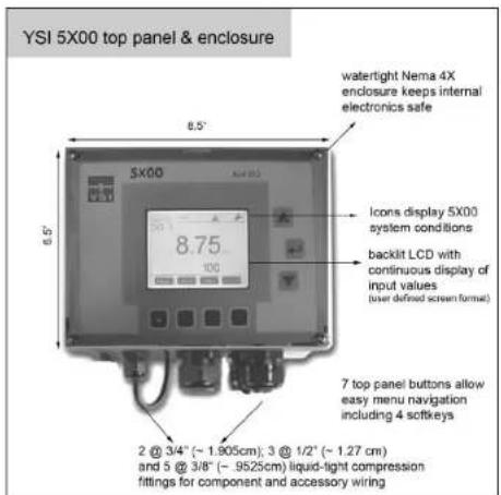
Figure 1.1
Preview of User Manual
This manual includes information on installing, configuring, operating, and maintaining a 5X00 system. YSI 5400, 5500D-01, 5500D-02 and 5500D-04 instruments have many similarities. Therefore "5X00" is used throughout this manual to refer to YSI 5400, 5500D-01, 5500D-02 and 5500D-04 instruments. 3500D-01, 3500D-02 and 5500D-04 at times are referred to collectively as 5500D instruments. Instructions, information and features specific to either YSI 5400 or YSI 5500D instruments will be referenced by using 5400 or 5500 in the left margin next to specific information.
Read Chapter 2 "Safety Information" starting on page 20 before installing or configuring a 5X00 system.
Chapter 3 "Installation" starting on page 26 provides information on how to install the 5X00, 5X00 components, and peripheral devices. Only qualified people should install a 5X00 system. Do not attempt to install or configure this device if you are not qualified to do so. If information is not clear, DO NOT PROCEED until clarification can be obtained. All wiring involving connections to main power must be performed by a qualified licensed electrician and must conform to all locally applicable electrical codes.
Chapter 4 "Configuring 5X00 Systems" starting on page 72 provides information on configuring 5X00 instruments.
Chapter 5 "AquaManager" starting on page 197 provides general information regarding the PC software program. The AquaManager program includes an extensive on-line help system which contains detailed information that is not provided in this manual.

This icon is used throughout the manual to indicate helpful information for Aqua-Manager users.

Is used to bring attention to new 5X00 instrument and AquaManager features and functionality.
Chapter 6 "Maintenance" starting on page 208 provides information on maintaining the 5X00 system including monitor and sensor service.
"Notes" at the end of each manual section provide additional information to help clarify certain 5X00 operations and features.
Appendices include information on Unpacking & Inspection, Troubleshooting, Menu Maps, Declaration of Conformity, Parts and Accessories, SMS Messaging, Warranty, Contact Us, Alpha "A" Curve and Recycling information.
An index is provided starting on page 260.
This is an interactive pdf file. Page numbers provided throughout the manual are linkable. Hover mouse over page number and click mouse to go to link.
Product Specifications
To ensure accurate and reliable performance, operate the 5X00 system according to the specifications provided in the following tables. Damage and/or incorrect operation could result if these specifications are not followed.
Product specifications are subject to change without notice. Visit www.ysi.com to view the most recent product specifications.
Environmental Specifications
| Environmental Category Operating Range | |
| Temperature -15 to 70°C (5 to 158°F) | |
| Enclosure Rating NEMA 4X (direct exposure to outside conditions) IP65 | |
| Compression Fitting Rating IP 68/NEMA 6 (liquid tight) | |
| Electrical Safety IEC compliant.* | |
| Other RoHS compliant | |
See Appendix 4 Declaration of Conformity - 248.
Input System Specifications
| Aux Systems | There are 6 Aux input systems that allow digital or analog (0-1.0VDC, 0-5.0VDC, or 4-20mA) configuration. In addition, four of the Aux systems can be configured as temperature systems see Temperature Systems Specs - 15. | |
| Aux System Type Digital Analog | ||
| Range dry contact | open/close 0 -1.0 VDC, 0-5.0 VDC, or 4-20mA | |
| Accuracy n/a 0-1.0 | VDC: ±3% ±10 mV | 0-5.0VDC: ±3% ±15 mV4-20 mA: ±3% ±100μA |
| Resolution n/a user | selectable (0), (0.0), or (0.00) | |
| DO Systems | There are up to 4 independent DO systems. Each DO system has 2 control ↑ranges, 2 control ↓ ranges, and high and low alarming. |
| Sensor Type5400 | Galvanic (mV) |
| Membrane Type | Teflon (TE), 2 mil (gray) |
| Range | 0 to 500% air saturation0 to 60 mg/L |
| Accuracy | ±2% or ± 0.2 mg/L, whichever is greater for 0-200%±6% of reading for 200-500% |
| Resolution | 0.1% (0.0-99.9%); 1% (>99.9)0.01 mg/L (0-10 mg/L); 0.1 mg/L (10-60 mg/L) |
| Response Time | 95% of reading in 36 seconds for 2.0 mil Teflon membrane. |
| Cable lengths | 4, 10, 20 m (special order up to 100m) |
| Flow requirements | 6 inches per second or 15.24 cm/second for 2.0 mil Teflon membrane |
| Other | manual salinity compensation for DO mg/L readings |
| Sensor Type5500D-01, 5500D-02,5500D-04 | Optical Dissolved Oxygen (dynamic luminescence quenching lifetime detection) |
| Dimensions | 19 cm length (7.5 in); 2.4 cm diameter (0.95 in) |
| Membrane Type | Sensor Cap includes calibration coefficients |
| Range 0-500% air saturation | 0 to 50 mg/l. |
| Accuracy | ± 0.2^ C |
| Salinity Input Range | 0-50 ppt |
| Storage Temperature | -20 to 70°C |
| Operating Temperature | -5 to 70°C |
| Response Time | 90% in 25 seconds; 95% in 45 seconds |
| Cable lengths | 1-4-10-20-30-40-50-60- and 100-m;(3.3, 13.1, 32.8, 65.6, 98, 131, 164, 197 and 328 ft) |
| Flow requirements | None |
| Temperature Systems | There are 4 independent temperature systems. Auxiliary inputs 3, 4, 5, & 6 can be configured as temperature systems. Each tem-perature system has 1 control ↑range, 1 control ↓ range, and high and low alarming. Temperature systems can be configured as the temperature source for DO measurements on a 5400 or as stand alone systems on either 5400 or 5500 instruments.. |
| Sensor type | 10,000 ohm @ 25°C thermistor |
| Range | 0-45°C; 32-113°F |
| Accuracy | ±0.2°C |
| Resolution | 0.1°C |
Component and System (non input) Specifications
| Hardware System | System Feature Specification | |
| Display/LEDs back | dit graphic LCD (320X240) with timer | readings updated 2 times a second |
| diagnostic troubleshooting LEDs | ||
| Outputs 8 on-board | relays 240VAC@ 5AMPs switching capacity; 110VAC@10AMPS; type: SPDT | |
| Electronics ARM7 | embedded microprocessor | |
| DSP (digital signal processing) Digital processing of 5X00 information ensures accurate and repeatable readings | ||
| Power: There are two 5X00 versions available. The DC version can only be powered by DC power. The AC version can be powered by AC or DC power. | ||
| Power for DC Version: | external 12VDC power source 9 | 16.5VDC; 800 mA |
| Power for AC Version: | internal AC switching power supply | 100-240VAC; 50-60Hz; 300 mA |
| Both AC and DC versions: | lithium battery (for real time clock) | 2032 lithium ion |
| Firmware System | Firmware Feature Specification | |
| Timer Systems 4 | timers 10 daily events per timer system | |
| 4 feed timers includes sensor & PCR control | ||
| Flash Memory | Firmware field upgradable with local PC connection | |
| Data Logging | non-volatile data log memory | |
| storage of 4750 records | ||
| sensor log (2000 records) | ||
| event log (1250 records) | ||
| calibration log (500 records) | ||
| Configuration log (1000 records) | ||
| Security password protection | ||
| Data filtering | reads 2-3 times per second; readings are averaged | |
| Communication | Feature | Specification |
| RS232 | up to 100 ft (30m) | |
| OR | Optional serial to ethernet device | remote TCP/IP PC access and/or email alarming |
| Instrument to Instrument Networking | Feature | Specification |
| Network 2 to 32 isolated 5X00 and/or 5200A instruments | RS485 up to 4000 ft (1220m)entire network distance | |
| AquaManager | Feature | Other PC Requirements |
| Runs on Windows 2000/XP/Vista/Windows 7 operating systems 32-bit and 64-bit | PC capable of running Windows 2000VGA display cardCD-ROM DriveTotal RAM Installed 16Mega or greater100 MB free hard-disk space |
This page left intentionally blank.
2 Safety
IMPORTANT safety information. Read this chapter before installing 5X00 components and peripheral devices.
THIS IS IMPORTANT
Take time to be safe when working on electrical circuits and equipment. It could save your life. Avoid unsafe acts and conditions. Do not operate or install the 5X00 before reading this chapter. Installing the 5X00 involves wiring high voltage equipment. Follow all provided safety information. Installation must be performed by someone who understand the dangers of, and is qualified to, wire electrical devices. If information or instructions are not clear, DO NOT PROCEED until clarification can be obtained.
ALWAYS:
Follow basic safety rules when working with or near high voltage circuits. The 5X00 is a high voltage instrument using 110v. Peripheral devices may also be high voltage devices.
Consider the result of each act. Keep away from live circuits. Do not change parts or make adjustments inside the equipment with high voltages on.
Do not service alone.
Do not tamper with interlocks. Safety devices such as interlocks, overload relays, and fuses should never be altered or disconnected except for replacement. Safety protection devices should never be changed or modified without a clear understanding of what effect the modification will have on the system.
Do not ground yourself.
Do not energize equipment if there is any evidence of water leakage.
Warnings and Cautions
Safety information is presented in this manual in one of two ways:

- WARNING - RISK OF ELECTRIC SHOCK This symbol identifies installation and operation procedures that can result in personal injury or death if safety information is not followed.

- CAUTION - RISK OF DANGER This symbol identifies installation and operation procedures that can result in personal injury or damage to equipment if safety information is not followed.
These symbols (△) (△) appear in the left margin of the page to highlight safety information as it applies to a particular installation or operation step.
A complete list of all safety cautions is provided below. Warnings are provided in both English and French.
Install and use the 5X00 only in accordance with information documented in this manual.
Warnings
WARNINGS are used when personal injury or death can result when safety information is not followed.

WARNING: All wiring involving connections to mains power must be performed by a qualified licensed electrician, and must conform to all locally applicable electrical codes.

WARNING: Do not make connections while power is applied. Turn off power and assure power "Lockout" before installing or servicing to avoid contact with electrically powered circuits. This includes working on devices connected to the relay outputs and auxiliary input systems. Disconnect external power to the 5X00 before connecting or disconnecting components and/or peripheral devices.

This page left intentionally blank.
3 Installation & Wiring
-Installing & wiring 5X00 components and peripheral devices
Hardware Installation
Correctly install 5X00 system components to ensure accurate data collection and reliable operation. First, determine what monitor, control, and alarm functions the 5X00 system will perform. Because system components are wired to the 5X00 instrument, it is important to determine where and how components will be installed and configured. Preparing a system schematic (figure 3.1) is helpful.

flowchart
graph TD
    A["AquaManager\nRemote TC/IP access"] --> B["5X00"]
    B --> C["Email server"]
    C --> D["Tank 1 location"]
    D --> E["Output control devices\nfeeder - Feed timer #1, relay 5"]
    D --> F["Input devices"]
    E --> G["feeder"]
    F --> H["aoerator"]
    G --> I["DO probe"]
    H --> J["Flow switch"]
    I --> K["DO - probe channel 1"]
    J --> L["flow - switch Aux #1, digital"]
    K --> M["260v"]
    L --> N["Email alarms"]
    M --> O["Aquay Manager\nRemote TC/IP access"]
    N --> P["Aquay Manager\nRemote TC/IP access"]
Figure 3.1
Hardware installation steps (not all steps required for all applications):
Step 1 - install 5X00 instrument
Step 2 - locate and install sensor(s)
Step 3 - ground 5X00
Step 4 - wire power
Step 5 - wire sensors(s)
Step 6 - wire relays (output devices)
Step 7 - wire aux input devices (excluding temperature probes)
Step 8 - wire a network of 2 - 32 instruments
Step 9 - install and wire communication equipment
Step 10 - install and wire IOEM and REM instruments (optional). IOEM/REM Installation information is included in a separate manual. See IOEM/REM Installation and Safety Guide.
See Chapter 4 Configuring 5X00 Systems - starting on 72 for directions on programming 5X00 systems.
Tools and supplies needed for hardware installation:
- Phillips-head screwdriver to remove 5X00 front panel to access I/O board and lower board assembly
- necessary tools for cutting mounting holes in mounting brackets (rail mount) and/or control panel (panel mount)
• 5/32" Allen wrench (panel mount only) - electric drill and bits for mounting 5X00 (panel or rail) and for drilling rubber grommets in bulkhead fittings
- small flat-head screwdriver to terminate wires on I/O board pluggable terminal strips
- wrench to tighten bulkhead fittings following system component wiring
- tweezers to replace the membrane gasket on the YSI 5422 sensor
- wire strippers
• distilled water for DO membrane installation - contactors may be required for relay wiring; see contactor wiring - page 55.
Optional accessories for hardware installation:
• surface mount hardware (included)
- rail mount hardware
• panel mount hardware
• weather shield hardware
• serial to ethernet device
• wiring for network wiring
• wiring not supplied with components and/or peripheral devices
Step 1 Install 5X00
Select a mounting location and method to mount the 5X00.
Location Considerations
The 5X00 must be located:
• above any level where water damage can occur
• away from extremely high or low temperature sources
• away from vibrating surfaces
• at least two 2 feet ( .7 m) from any high voltage conduit
• away from electromagnetic, radio, AC motor, transformer, or antennas
• so the front panel can be fully opened and serviced
- so system component wires are run as specified in this manual and according to local applicable electrical code
Mount the 5X00
Select surface, rail, or panel mount option. Install the weather shield for outdoor installations.
Surface Mount
Mount 5X00 to any flat surface using mounting brackets. Mounting brackets and screws are included with the 5X00.
- Fasten the mounting brackets to the back of the 5X00 with the mounting screws - figure 3.2.
- Tighten the screws, securing the brackets to the back of the 5X00 enclosure.
- Fasten the 5X00 mounting brackets to the mounting surface with the mounting screws provided - figure 3.2. Make sure screws adequately secure 5X00 to surface.
- Tighten the screws, securing the 5X00 to the surface.

Figure 3.2
Rail Mount
Mount 5X00 to handrail or pipe 1 to 1.5" (2.5 to 3.8cm) in diameter. The rail mount kit (YSI model number 6509) includes u-bolts, a pre-drilled metal plate, washers, and nuts.
- Drill holes in the mounting brackets to fit the u-bolts. Use the pre-drilled metal plate as a template.
- Fasten the mounting brackets to the back of the 5X00 with the mounting screws as shown in figure 3.2.
- Tighten the screws, securing the brackets to the 5X00.
- Place the u-bolts around the rail securing the 5X00 to the pipe or rail by feeding through the pre-drilled holes on the mounting brackets as shown in figure 3.3.
- Secure the metal plate over the u-bolts and around the rail or pipe using washers and nuts provided.
- Tighten the screws, securing the 5X00 to the rail.

Figure 3.3
Panel Mount
Panel mount the 5X00 if the 5X00's front panel is to be mounted on a control panel or any vertical surface where only the front panel will be accessible from the mounting surface. The panel mount kit (YSI model number 6510) includes the standoffs and frame necessary to mount the 5X00 to any panel 9.5" l x 7.5" w (\~24x19cm). The space behind the panel must be at least 5.5" (14cm) deep.

WARNING: Disconnect external power to the unit before opening the front panel.

- See Open Front Panel to Access I/O Board - page 41 to remove front panel from enclosure.

Figure 3.4
- Disconnect front panel ribbon cable by pressing the two IDC header connectors located on the front panel out (away from the IDC header) - figure 3.5.

Figure 3.5
- Remove and retain four screws that secure display board into top panel enclosure - figure 3.6. (Display board is mounted on panel attached to 5X00 top panel. I/O Board wiring diagram is located on the display board panel.)

Figure 3.6
- Carefully lift out the display board and remove the lanyard from the display board panel - figure 3.7. Set display board panel and top panel aside.
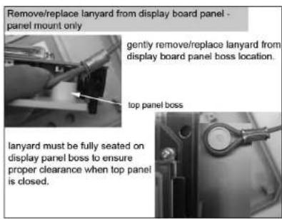
Figure 3.7
- Fasten the mounting brackets to the back of the 5X00 enclosure with the mounting screws - figure 3.2 - page 28.
- Tighten the screws, securing the brackets to the 5X00.
- Drill hole in panel for 5X00 enclosure (dimensions provided with kit).
- Place standoffs between 5X00 mounting brackets and panel surface - figure 3.8 - page 32.
- Secure 5X00 to panel with frame using washers and bolts provided.

Figure 3.8
- Reattach lanyard by placing lanyard at proper location of display board panel. Make sure lanyard is fully seated on display panel boss to ensure proper clearance when front panel is closed- figure 3.7.
- Replace four screws to reattach display board panel to front panel enclosure - figure 3.6.
- Connect 5X00 display board to ribbon cable - figure 3.5.
- Secure the 5X00 front panel to the frame using mounting screws. Follow procedures provided at Close Front Panel - page 41 to secure 5X00 and protect internal electronics.
- Tighten the screws, securing the 5X00 to the panel.
Install the Weather Shield
Install the weather shield for outdoor installations. The weather shield can be used with either a surface or rail mount. The weather shield kit (model number 6505) includes a weather shield, u-bolts, pre-drilled metal plate, washers, and nuts.
- First complete steps 1-2 under Surface Mount or steps 1-3 under Rail Mount depending on the type of installation. Note: You may need to modify the pre-drilled holes in the weather shield depending on the mounting location.
- At step 3 (surface mount) or step 4 (rail mount), attach the weather shield with the metal plate installed securely to the surface or rail. Figure 3.9 shows the weather shield installed for a rail mounted 5X00.
- Tighten the screws, securing the weather shield.

Figure 3.9
Step 2 Locate and Install Sensor(s)
Throughout the manual, the term "probe" refers to the end of the cable where the sensor is located and the term "sensor" refers to the sensing portion of the cable/probe assembly.
DO Sensors
5X00 instruments can be configured with 1, 2, 3, or 4 dissolved oxygen (DO) sensors depending on the model. (models 5400 and 5500D-04 can be configured with up to 4 DO probes; model 5500D-02 can be configured with up to 2 DO probes; model 5500D-01 can be configured with 1 DO probe.) Auxiliary (aux) inputs 3, 4, 5 and/or 6 can be configured as temperature inputs. YSI 5400 instruments use a YSI 5421-X DO (galvanic)/temperature, and/or a YSI 5420-X DO (galvanic) sensor assembly. YSI 5500 instruments use YSI 626250 ODO (Optical Dissolved Oxygen) sensors.
DO sensors for 5400 instruments require a properly installed membrane. The 5420 and 5421 galvanic sensors use a 2 mil Teflon membrane. ODO sensors for 5500 instruments require a sensing cap. 5500 instrument sensor caps are factory calibrated with sensor cap coefficients. It is important to retain sensor cap coefficients (provided by YSI) for the life of the sensor.
Temperature Sensors
Temperature sensor(s) must use a 10K thermistor (at 25°C). See Appendix 6 Alpha A Curve - page 256.
5400
Aux temperature sensors can be configured as the temperature source for DO systems on YSI 5400 instruments. Aux temperature sensor(s) cannot be configured as DO temperature sources on YSI 5500 instruments. YSI 5500 DO systems always use the temperature from the YSI ODO probe. For accurate DO measurements, ensure that the temperature reading for each DO channel is representative of the temperature at that DO sensor's location. This is important when using the same temperature input source for multiple DO sensors. Example - if the temperature source for DO1 and DO2 is the temperature sensor connected to Aux 3 at the DO1 sensor location, it is important that the temperature at the DO2 sensor location is the same as at DO1 sensor location.
See Chapter 4 Sensor Setup - page 150, for information on configuring 5X00 sensor systems. User defined DO system configuration items include:
- Display format (i.e. units of measure. For example, mg/L or % saturation, °C or °F);
-
Temperature source (5400 only);
-
Salinity input value (user entered salinity value of the water being monitored);
- Elevation;
- Setpoint, control, and alarm values and ranges;
- Control and alarm relay assignments;
Location Considerations
Readings gathered at the sensor location(s) are data logged and processed by the 5X00 instrument. Output control and alarm devices are configured to respond to sensor values. Therefore, it is essential to have accurate readings at the sensor location. Locate sensors according to the below specifications.
5400
Locate sensor end of probe assembly:
• in a location that represents the entire system
- where the water flow is at least 6 inches per second (15.24 cm/sec) for 2.0 mil Teflon membrane
- in a location that is free from debris (e.g. algae); ideally at a 45° angle from vertical position and directed with the flow - figure 3.10
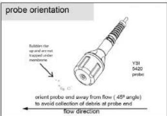
Figure 3.10
- in a well mixed, free-flowing area; midstream and mid-depth typically gives representative readings; the probe assembly and cable are fully submersible up to the cable connector
- submersed at all times so liquid level fluctuations do not expose the sensors to the atmosphere
- so the sensor/probe cabling is not routed near rotating machinery and/or equipment involving electrical switching or regulation
- so that the sensor assembly and cabling are located away from sources of electrical interference such as UV sterilizers, fluorescent lighting, ballasts, pumps, any high voltage peripheral devices, etc.

CAUTION: run high and low voltage cabling through separate bulkhead and conduit
- where regular maintenance, including calibration can easily be done. Calibrations are performed using the 5X00 front panel.
Note:
If a 5420 or 5421 sensor requires replacement, the entire probe/cable assembly must be replaced.

Locate sensor end of probe assembly:
• in a location that represents the entire system
- Insert the probe into sample. Move the probe in the sample to release any air bubbles and to provide a fresh sample to the sensor cap. This movement is only necessary when first inserting the probe into the sample.
- Since the ProODO utilizes optical luminescent technology, continuous sample movement or stirring is not required. (Please note however that flow does increase response time of sensor.) The probe will fit into a 300 mL BOD bottle for taking initial and final BOD readings. For best results in a BOD bottle, a stirring device should be used to properly mix the sample and to keep solids from settling at the bottom.
- Allow the temperature readings to stabilize and wait approximately 25-35 seconds for the DO readings to stabilize.
- in a location that is free from debris (e.g. algae); ideally at a 45° angle from vertical position and directed with the flow.
- in a well mixed, free-flowing area; midstream and mid-depth typically gives representative readings; the probe assembly and cable are fully submersible up to the cable connector.
- submersed at all times so liquid level fluctuations do not expose the sensors to the atmosphere.
- so the sensor/probe cabling is not routed near rotating machinery and/or equipment involving electrical switching or regulation
- so that the sensor assembly and cabling are located away from sources of electrical interference such as UV sterilizers, fluorescent lighting, ballasts, pumps, any high voltage peripheral devices, etc.

CAUTION: run high and low voltage cabling through separate bulkhead and conduit

YSI 5420 and YSI 5421 (Galvanic) probe assemblies
The YSI 5420 probe/cable assembly includes a galvanic DO sensor. The YSI 5421 includes a galvanic DO and temperature sensor. The DO sensor on both of these cables is shipped with a dry membrane. A new membrane with fresh electrolyte must be installed on the DO sensor prior to use. Complete instructions are provided with the sensor and membrane kit.
Figure 3.12 shows the external parts of the YSI 5420 probe/cable assembly.
After installing the probe in its monitoring location, see Wire Sensors - page 49 for wiring directions.
Probes should be serviced on a regular basis. See DO Probe Maintenance - page 211.
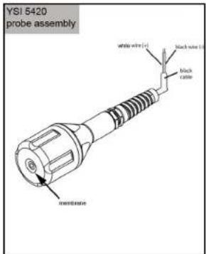
Figure 3.12

YSI 626250 ODO (Optical Dissolved Oxygen) sensor
The YSI 626250 probe assembly includes an ODO sensor and sensor cap. Sensor cap refers to the removable sensing cap that is replaced about once per year (Figure 3.12a) YSI 626250 probe assembly includes a temperature sensor. An instruction sheet is included with replacement sensor caps. This instruction sheet is important because it includes the calibration coefficients for your sensor cap. After using this sheet for general probe setup, be sure to store it in a safe place in case you need to reload these calibration coefficients in the unlikely event that they are ever deleted from the probe.

Figure 3.12a
Directions to prepare the ODO probe for the first time:
- Remove the metal probe guard from the probe by turning it counterclockwise.
- Remove the red storage cap which contains a moist sponge from the end of the probe by pulling it straight off the sensor. Save this to use later for long term storage.
- Reinstall the probe guard by sliding it carefully over the sensor and then threading it onto the cable/probe assembly with a clock.
- Calibrate probe - page 83.
Notes:
- A new cable/probe assembly already has a sensor cap installed and the sensor cap coefficients are preloaded into the probe at the factory.
- Perform ODO calibration whenever ODO caps are replaced see Calibration page 83.
Install Temperature Sensors
The 5X00 system will support 4 Temperature/Aux Analog inputs. Temperature sensors are included on YSI 5421 (galvanic) and 626250 sensor and/or sensor assemblies. Alternate temperature sensors can be used but must be thermistors with 10K at 25°C. See Appendix 6 Alpha Curve - page 256.
After installing the temperature sensor in its monitoring location, see Wire Temperature Sensors - page 52.
Probes should be serviced on a regular basis. See Probe Maintenance - page 211.
Wiring Information
System components must be wired correctly to ensure reliable performance and accurate data collection. Directions are provided on the following pages for wiring all components and peripheral devices.
PCBs
There are four printed circuit boards (PCBs) inside the 5X00 enclosure. They are:
- Display board (mounted in the front panel)
- 1/O board is attached to a metal plate inside the enclosure and is visible when front panel is removed
- DO daughter board mounted to the I/O Board
- Control board (connected to the under side of the I/O Board)
Notes:
- I/O board and control board (including DO daughter board) are attached to a metal plate and are referred to as the "lower board assembly". See Control Board - page 42.
- No 5X00 components or peripheral devices are wired to the display or DO daughter board.
Most components including: power, Aux input, network, relay output, and RS232 communication components are terminated on the I/O board. 5X00 ground wire and sensor ground wires (also called drain wires) are terminated to the metal plate that is attached to the lower board assembly. The optional serial to ethernet device is installed on the control board. The front panel must be removed when wiring 5X00 components and peripheral devices. See Accessing the I/O Board - page 40. It is recommended that some system configuration and testing be done in conjunction with hardware installation. This will ensure that the 5X00 system is wired correctly. Necessary configuration information (from Chapter 4 - "Configuration") is referenced in the applicable test system procedure.

WARNING: Follow all safety information and local electrical codes when wiring 5X00 system components and peripheral devices. Proper wire gauge should be determined based on voltages and wire/cable length. Incorrect wiring can result in damage to you or equipment. Ground loops can also result due to improper wiring.

5X00 Bulkhead Fittings
Five bulkhead fittings [5@ 3/8"(.9525cm), 2 @ 3/4" (1.905cm) and 3@ 1/2" (1.27cm)] located at the bottom of the 5X00 enclosure provide watertight connections for 5X00 system component wiring. Rubber grommets must be "pushed out" of the compression fitting housing and drilled for wiring installation. The drill bit diameter should be slightly smaller than the wire diameter so that a watertight seal can be made. Rubber grommets can be frozen (put in a freezer for 1 hour) and then easily drilled to the required diameter. Some pre-drilled rubber grommets are supplied with the 5X00.
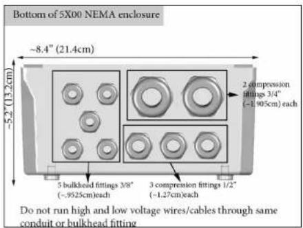
Figure 3.13
Accessing the I/O Board
The I/O board is accessible when the 5X00 front panel is removed. The letters on the metal plate, which is attached to the lower board assembly, identify ground wire termination locations and pluggable terminal strip locations on the I/O board. Letters on the metal plate correspond to the wiring diagram located on the inside of the top panel - figure 3.14. A ribbon cable connects the display board (mounted in the top panel) to the I/O board. When the 5X00 top panel is removed, a lanyard protects
against stress on the ribbon cable. See Open Top Panel to Access I/O Board - page 41.
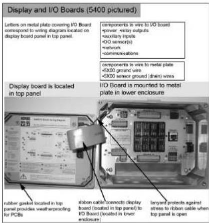
Figure 3.14
Open Front Panel to Access I/O Board

WARNING: Disconnect external power to the unit before doing any wiring.

- Loosen the 4 mounting screws connecting the front panel to back enclosure. Captive screws remain in front panel after loosening.
- Carefully lift the 5X00 front panel from the back enclosure. The front panel should be placed to the left of enclosure. Allow the lanyard to hold the weight of the front panel. The rubber gasket seated in the front panel should remain in the front panel lid.
Close Front Panel
-
Verify all installed components and peripheral equipment have secure connections and that there are no bare wires that could cause a short inside the enclosure.
-
Tighten bulkhead fittings after connecting all 5X00 wiring. (Hand tighten fittings around rubber grommet. Tighten bulkhead fittings into 5X00 enclosure with wrench being careful to not overtighten.)
- Follow information in Sealants, Desiccants and Securing the Monitor Section - page 69 to safeguard against damage to internal electronic components.
- Make certain the gasket in front panel lid is in place and not twisted or damaged.
- Replace front panel making sure that ribbon cable is not trapped in the gasket channel before inserting mounting screws.
- Tighten mounting screws, making sure not to cross thread. The screws are stainless steel, and the receiving threads are brass. Do not over-tighten!

WARNING: The 5X00 utilizes sensitive solid-state devices that can be damaged by static shock. Installers must observe accepted ESD (Electro-Static Discharge) procedures while connecting cabling to the 5X00 1/O plate or to any other internal component or damage may result.

The control board is mounted underneath the I/O Board. The serial to ethernet device and lithium battery are installed on the control board. Complete installation instructions, including accessing control board, are provided with the optional serial to ethernet device. Figure 3.15 shows the control board and I/O Board removed from the 5X00 enclosure.

Figure 3.15
Step 3 Ground 5X00

WARNING: Ground the 5X00 to avoid possible electrical shock or damage to the equipment.

Ground the 5X00 at location G on the metal plate. The metal plate is attached to the lower board assembly. Use locations F and F to ground the DO sensor ground/drain wires - figure 3.16. (Common lettering references are used for both 5400 and 5500 models). Titanium ground rods can also be used to ground peripheral equipment.
In addition to grounding the 5X00, all tanks should be electrically grounded via a ground probe.
Directions to Ground 5X00

WARNING: Disconnect external power to the unit before wiring.

- Perform steps 1 - 2 of 5X00 installation.
- Open front panel - page 41.
- Remove screw from location F or G.
- Feed ground wire through drilled hole in rubber grommet and to location F or G on metal plate covering I/O Board. Ground wire gauge must conform to all locally applicable electrical codes.

CAUTION: Run high and low voltage cables through separate bulkhead and conduit.
- Install a ring (eyelet) or spade (fork) terminal onto the ground bare wire before terminating ground wire to F or G.
- Return screw at F or G over terminal connection of ground wire.
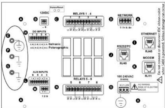
Figure 3.16
- Terminate other end of the earth ground wire to a cold water pipe, steel rod, copper pipe, or earth ground.
- Complete other wiring to configure 5X00 system.
- Close front panel - page 41.
Step 4 Wire Power
5X00 instruments are available with either AC or DC power. The DC version can only be powered by DC power. The AC version can be powered by either AC or DC. If an AC version is properly wired and configured for AC and DC backup, and AC power fails, the instrument will be powered by the DC backup which supplies backup power. If DC voltage drops below a user defined safe operating range, an alarm occurs.

CAUTION: At 120VAC, the 5X00 draws 25 watts (\~0.2 amps). Use wiring suitable for that load following all safety information and local electrical codes.
Back up power is recommended when operating with AC power. Backup power can be supplied by 12VDC or UPS battery source.
Wire AC Power
The AC power option includes an integrated universal (worldwide) AC switching power supply allowing AC power from any AC receptacle 100-240VAC. AC power wires are terminated at location ① on I/O Board - Figure 3.17. (Common lettering references are used for both 5400 and 5500 models).
Directions to Wire AC Power

WARNING: Disconnect external power to the unit before wiring.

- Perform steps 1-3 of 5X00 installation.
- Open front panel - page 41.
- Feed AC power cable through drilled hole in rubber grommet to location ①. The terminal strip is removable.

CAUTION: Run high and low voltage cables through separate bulkhead and conduit.
- Terminate AC power wires to pins "G" (ground), "L1", and/or "L2/N" according to applicable local electrical codes. Use minimum 18 gauge 3 wire power cord.

CAUTION: It is recommended to power only the 5X00 instrument with the power cord to prevent exceeding the current draw of the AC power supply.

Figure 3.17
- Complete other wiring to 5X00.
- Close front panel - page 41.
- Test AC power.
Test AC Power
Turn on main power. The enabled system values display on the Run Screen after initial YSI splash screen. If applicable, install and configure DC power backup 46. Verify AC power at the Menus → System → Version menu - page 148.
See power fail menu - page 138 for AC power event log information.
Wire DC Power and Backup Power
The 5X00 may be powered by most regulated 9.0-16.5 VDC sources that provide 800mA of current and are isolated from mains supply by double or reinforced insulation. The DC backup power source is user supplied and could be lead acid, gel cell, or UPS (with 12VDC transformer) external batteries. DC power wires are terminated at location ⑤ on the I/O Board - Figure 3.18 (Common lettering references are used for both 5400 and 5500 models).
Notes:
- The 5X00 does not charge batteries. Quality assurance maintenance procedures should be established if batteries are to be fully powered when used as back-up power source.
- Power supply voltage above 16.5 VDC may permanently damage the 5X00.
- When back up voltage falls below 9.0 volts, the 5X00 ceases to operate properly.
- Some switching DC power supplies not supplied by YSI may result in noisy readings.
Directions to Wire DC Power/DC Backup Power

WARNING: Disconnect external power to the unit before wiring. Follow all manufacturer's safety and installation instructions when providing power to the 5X00 via a DC power supply.

- Perform steps 1-3 of 5X00 installation.
- Open front panel - page 41.
- Feed DC power cable through drilled hole in rubber grommet to location B. Terminal strip is removable.

CAUTION: Run high and low voltage cables through separate bulkhead and conduit.
- Terminate DC power wires to pins (-) and (+) according to manufacturer instructions and any applicable local electrical codes.

Figure 3.18
- Complete other wiring to 5X00.
- Close front panel - 41.
- Test DC power.
Test DC Power
Connect DC power cable to power source. The enabled system values will display on Run Screen after initial YSI splash screen. Verify DC power at the Menus → System → Version menu - page 148.
See Power Fail Menu - page 138 for DC low battery trigger monitor and alarm information.
Note:
The 5X00 will not power up if DC power supply wires are terminated incorrectly.
Step 5 Wire Sensor(s)
Depending on the 5X00 model, up to four DO sensors and four temperature sensors can be wired to the 5X00. All sensors are wired to the I/O Board - figure 3.19 and 3.19a. Use location E or F on metal plate to ground the DO sensor ground/drain wires. (Common lettering references are used for both 5400 and 5500 models). Follow the wiring instructions below to ensure proper sensor operation.
5400 YSI probe assembly 5421 has one galvanic DO sensor and one temperature sensor. YSI probe assembly 5420 has one galvanic DO sensor. The probe assemblies are shipped bare wire. YSI 5421 and has five wires. Two wires are for the DO sensor and are terminated at location H on the I/O board. Two wires are for the temperature sensor (YSI 5421) and are terminated at location L on the I/O board. Terminate the fifth wire (ground/drain wire) to location E or F of metal plate. The YSI 5420 probe assembly has three wires for the DO sensor and does not include any temperature sensor wires.
5500 ODO probe assemblies have five wires. Four ODO sensor wires are terminated at location H. Terminate the fifth (ground/drain wire) to location E or F of metal plate. Complete directions and wiring diagram are provided at step 4 (5500) - page 50. The ODO probe is a digital device and includes a temperature sensor.
Wire DO Sensors
Directions to Wire DO Sensor(s)

WARNING: Disconnect external power to the unit before wiring.
- Perform steps 1 - 4 of 5X00 installation.
- Open front panel - page 41.
- Feed DO cable through drilled hole in rubber grommet to location H. The terminal strip is removable.

CAUTION: Run high and low voltage cables through separate bulkhead and conduit.

- Terminate the DO sensor wires for the DO1, DO2, DO3, and/or DO4 system(s). Wire the DO sensor cathode wire to (+) terminals and the DO sensor anode wire to (-) terminals. Follow the coloring scheme described below when wiring the DO sensor.
• YSI 5420 & 5421 galvanic DO sensor wires are white and black.
-Terminate white wire to "C Galvanic".
-Terminate black wire to "A Galvanic".
-Terminate bare ground/drain wire to E or F on metal plate.
Installation and Wiring
- Install a ring (eyelet) or spade (fork) terminal onto the ground bare wire before terminating ground wire to E or F.
- Multiple ODO ground/drain wires can be terminated to the same ground location on the metal plate.
- Return screw at E or F over terminal connection of ground wire.
| YSI 5420 galvanic DO & 5421 galvanic DO/temperature analog sensor cable YSI | |
| Wire Function Wire label/color | |
| Cathode (C) (+) WHITE | |
| Anode (A) (-) | |
| YSI 5421 Temperature (There is no polarity for temperature sensor wire) | RED |
| YSI 5421 Temperature (there is no polarity for temperature sensor wire) | GREEN |
| Ground/drain wire BARE | |

Figure 3.19
Proceed to Step 5 following 5500 DO sensor wiring directions - page 52 to complete sensor wiring.

- On 5500D instruments there are two terminal strips at location H. Wire system DO-1 and system DO-2 sensors to the upper terminal strip. Wire system DO-3 and system DO-4 sensors to the lower terminal strip - see
Installation and Wiring
figures 3.19a and 3.19b. The upper and lower DO sensor terminal strips are inverted. Be sure ODO sensor wires follow the wire coding below.
| YSI 6060250 ODO/temperature digital sensor cable YSI | |
| Wire Function Color Coding | |
| power/6.3 volts DC for ODO Probe RED | |
| GND/Sensor GREEN | |
| RS485 B/bidirectional data WHITE | |
| RS485 A/bidirectional data | BLACK |
| Ground/drain wire BARE | |
- YSI 6060250 ODO DO sensor wires are red, green, white and black.
-Terminate red wire to 1R ("1" = DOI "R" = red) and/or 2R, 3R, 4R.
-Terminate green wire to 1G ("1" = DO1 "G" = green) and/or 2G, 3G, 4G.
-Terminate white wire to 1W ("1"=DO1 "W"=white) and/or 2W, 3W, 4W.
-Terminate black wire to 1B ("1"=DO1 "B"=black) and/or 2B, 3B, 4B.
-Terminate bare ground/drain wire to E or F on metal plate. pound/drain wire termination: - Install a ring (eyelet) or spade (fork) terminal onto the ground bare wire before terminating ground wire to E or F.
- Multiple ODO ground/drain wires can be terminated to the same ground location on the metal plate.
- Return screw at E or F over terminal connection of ground wire.

Figure 3.19a

Figure 3.19b
- Wire temperature sensors. Temperature sensors are wired as auxiliary inputs. See Temperature Sensor(s) - page 52.
- Complete other wiring to configure 5X00 system.
- Close Front panel -page 41.
- Calibrate DO sensor - see Calibration "DO" on page 83.

CAUTION: Do not ground the probe body.
Test DO/Temperature Sensors
Apply power to 5X00. See DO Sensor Setup - page 173 to configure DO sensor inputs. See Temperature Setup - page 168. Calibrate the DO sensor, see DO calibration - page 81. Verify changes in sensor values occur when the sensor is placed in environments of different oxygen concentration and temperature. For example, the DO reading in saturated air for calibration versus the DO reading when the sensor is placed in a zero oxygen environment (mix I gram sodium sulfite in 0.5 liter of water).
Wire Temperature Sensor(s)
The 5X00 system will support four 'Temperature/Aux Analog inputs. Temperature sensors have 2 wires and are terminated at location (K5500) L (5400) on I/O Board - figure 3.20. Temperature sensor(s) must be thermistors with 10K at 25°C, see Appendix 6 Alpha A Curve - page 256.
Installation and Wiring Installation
Directions to Wire Temperature Sensor(s)

WARNING: Disconnect external power to the unit before wiring.

- Mount and install 5X00 and probes - pages 27 and 34.
- Open front panel - page 41.
- Feed temperature probe cable through drilled hole in rubber grommet to location K (5500) L (5400). The terminal strip is removable.

CAUTION: Run high and low voltage cables through separate bulkhead and conduit.
4. Terminate temperature sensor wires to Aux 3, Aux 4, Aux 5, and/or Aux 6 system. There is no polarity for temperature sensor wires; therefore, (+) and (-) terminals are interchangeable. Make sure the temperature sensor wires are terminated to the (+) and (-) terminals for the Aux system (3, 4, 5, 6) you are configuring.

Figure 3.20
- Complete other wiring to configure 5X00 system.
- Close front panel - page 41
- Test temperature sensor.
Note:
- Temperature sensors wired to Aux 3, Aux 4, Aux 5, and Aux 6 are displayed on the 5X00 by default as Temp 1, Temp 2, Temp 3, and Temp 4 respectively. For instructions on changing the default display settings, see section Name Devices/Sensors in Chapter 4 Configuring the 5X00.
Test Temperature Sensor
Apply power to 5X00. See Temperature Set up - page 168 to configure temperature system. Place the temperature sensor in solutions of varying temperature and verify the sensor readings with another temperature sensor.
Step 6 Wire Relay outputs
The 5X00 has eight (8) on board non-fused relays rated at 240VAC@5AMPs (110VAC@10AMPs) of switching capacity. Relays energize and dc-energize peripheral control, alarm and/or timer devices. Terminate relay device wires to Normally Open (NO), Normally Closed (NC), and Common (C) sockets as required for the application. (See 5X00 I/O Board wiring diagram on inside of front panel for identification of relay number and pin position.) Relays 1-4 are terminated at location C on I/O Board. Relays 5-8 are terminated at location N on I/O Board - 3.21. (Common lettering references are used for both 5400 and 5500 models).

CAUTION: Do not overload relay(s). Check manufacturer specifications for inductive current/amp at power up. Use a contactor if necessary - figure 3.22. (Common lettering references are used for both 5400 and 5500 models).
Directions to Wire Relay Outputs

WARNING: Disconnect external power to the unit before wiring. If any of the relay contacts are connected to a "hazardous-live" circuit, ALL contacts on ALL relays must be considered "hazardous live" and appropriately protected from user contact outside the 5X00 enclosure.

-
Perform steps 1-4 of 5X00 installation and step 5 as required for application.
-
Open front panel - page 41.
- Feed relay device wires through drilled hole in rubber grommet and to locations C and/or N. The terminal strip is removable.

CAUTION: Run high and low voltage cables through separate bulkhead and conduit.
- Terminate relay device wires to the relay number (1-8) that will be configured for device. Wire devices to NC or NO and C pins depending on device configuration.

Figure 3.21
- Complete other wiring to 5X00.
- Close front panel -41.
- Test relays.
Wiring a Contactor
The eight onboard relays are rated at 240VAC@5AMPs (110VAC@10AMPs) switching capacity. Contactors should be used for devices drawing current loads higher than relay specification. See figure 3.22 for contactor wiring.
Note:
- Contactor must meet the electrical requirements of the load.

Figure 3.22
Test Relay Outputs:
Apply power to 5X00. Verify device activates at relay test. See Relay Test - page 144.
Note:
Entering the relay test menu turns off any active relays and disables any sensor, aux, and timer system relays from energizing regardless of value or condition. Systems are not reset when the Relay Test menu is exited. To reset systems after exiting the Relay Test menu, power cycle the 5X00.
Step 7 Wire Aux Inputs (Non Temperature)
The 5X00 has six (6) auxiliary inputs. All 6 auxiliary inputs can be used for digital (open/closed dry contacts) or analog (0-1VDC; 0-5VDC, or 4-20ma) inputs. Auxiliary inputs 3, 4, 5, and 6 can be configured for a temperature sensor. See Temperature Probes - page 52 for wiring directions. Aux inputs can be used for a variety of applications including: level switch, pressure switch, and/or an external instrument with an analog recorder output. Aux input wires are terminated at location L and/or M on I/O Board - figure 3.23. (See 5X00 I/O Board wiring diagram on inside of front panel for identification of aux system number and pin position.) See Digital Input example - figure 3.24, and Analog Input example - figure 3.25. (Common lettering references are used for both 5400 and 5500 models).
Notes:
- All aux inputs have input protection, the maximum input voltage should not exceed 6 VDC.
- Analog systems will not monitor and/or alarm properly if the device that is installed and configured operates outside the configured analog range.
- For proper digital input operation, use low impedance switches and wiring. The total resistance should not exceed 200 Ω (ohms).
Directions to Wire Aux Inputs (Non Temperature Inputs)

WARNING: Disconnect external power to the unit before wiring.

- Perform steps 1-4 of 5X00 installation and steps 5-6 as required for the application.
- Open front panel - page 41.
- Feed auxiliary device cable(s) through drilled hole in rubber grommet to locations L and/or M. The terminal strip is removable.

CAUTION: Run high and low voltage cables through separate bulkhead and conduit.
- For Aux 3, 4, 5, & 6 use the terminal strip located at L, using (+) terminal strip port for non ground wire and (-) for ground wire. For Aux 1 and 2, use terminal strip located at M. "G" pin is the common ground for Aux 1 and 2.
See Digital Input example - figure 3.24 and Analog Input example - figure 3.25.
CAUTION: The auxiliary inputs are not isolated. Devices connected must be electrically isolated from ground and the water.
Installation and Wiring
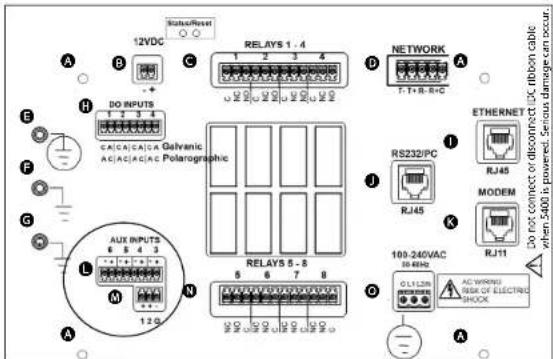
Figure 3.23
- Complete other wiring to 5X00.
- Close front panel - page 41.
- Test aux systems.
Test Auxiliary Input Devices
Apply power to 5X00. See Aux Setup - digital page 165 and analog (non temperature) page 166 for configuration information. Verify display, control, and/or alarm functionality based on user defined configuration.
Installation and Wiring
Wire Aux Digital Input
- Install aux digital device according to manufacturer's instructions.
- Connect switch wires to Aux Input 1 - 6. Connect ground wire to (G) at location M for aux 1 and 2 or to (-) at L for aux 3, 4, 5, or 6. Connect the other wire to (+) L and to 1 or 2 at M.

CAUTION: Do not input external voltage.
Figure 3.24
Wire Aux Analog Input
- Install analog instrument according to manufacturer's instructions.
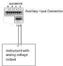
- Connect analog instrument wires to Aux Input 1 - 6. Connect ground wire to the (G) at M for aux 1 and 2 or to (-) at L for aux 3, 4, 5, or 6. Connect the other wire to 1 or 2 at M for aux 1 and 2 or to (+) at L for aux 3, 4, 5, or 6.


CAUTION: Observe correct polarity on analog input.
Figure 3.25
Step 8 Wire Network
Multiple 5X00 and 5200A instruments can be networked using the RS485 network ports. A node network consists of one master and up to 31 slaves. On a network, the master is the point of access for the AquaManager PC software program. In addition, the master sends all serial to ethernet device emails. Communication hardware (RS232 or serial to ethernet device) is installed on the master instrument (node) only.
RS485 network wiring can span distances up to 4000 feet (1220m). This maximum distance (4000 ft) is for the total network distance, not the distance between networked units (*see Notes below). RS485 ports are optically isolated for safety, to reduce noise, and to help eliminate ground loops. No further isolation is required.
Network traffic refers to the constant communication between the master and all slaves on the network. Example - slave node 3 is configured to generate an alarm if the temperature drops below 70^ . The master node is configured to send email alarms via TCP/IP using the serial to ethernet device. The master node sends an email alarm when slave node 3 reports a temperature value below 70^ to the master.

AquaManager is a valuable tool for monitoring and controlling node networks.
Notes:
- *Use an RS485 Line Extender/Booster for distances over 4000' (1220m). Communication failures may occur without it. Mount the booster in an area where it is protected from moisture.
- Multiple networks connected to a PC via RS232 require separate PC COM ports for simultaneous AquaManager mapping and autopolling.
- Legacy 5200s can not be on the same network as 5200As and/or 5X00s. However, Legacy 5200s can communicate with AquaManager and Legacy 5200 data will be stored in the same database as 5200A and 5X00 data.
- Network traffic speed operates at 230 KB and is not user selectable.
- Remove network terminal strip from any networked slave that is not powered. Network rewiring is required if a stub (*see note below) is created when a slave is taken off the network. See valid network configuration - see figure 3.30.

Note:
- * A stub is created when the last wired network terminal strip is not connected to a network slave - figure 3.26. (Common lettering references are used for both 5400 and 5500 models).
Network wire stub

flowchart
graph TD
    A["A stub created when the last wired network terminal strip is not connected to a network slave"] --> B["this is a stub"]
    B --> C["master"]
    B --> D["slave"]
    B --> E["slave"]
    B --> F["slave slave"]
    B --> G["the last wired terminal strip is physically connected to last physical slave on network"]
    H["this is not a stub"] --> I["master"]
    H --> J["slave"]
    H --> K["slave"]
    H --> L["slave"]
    H --> M["slave slave"]
    H --> N["the last wired terminal strip is physically connected to last physical slave on network"]

-represents wired network termination strip
-terminal strips located within master/slave image represent terminal strips that are physically
connected to device
-terminal strips that appear outside slave image represent terminal strips not connected to device
Figure 3.26
Directions to Wire Network
Network wiring consists of two pair of twisted pair cable plus a communications com wire. Category 5 ethernet cable is recommended. Network wires are terminated at location D on I/O Board - figure 3.27. (Common lettering references are used for both 5400 and 5500 models)

WARNING: Disconnect external power to the unit before wiring.

- Perform steps 1-4 of 5X00 installation and steps 5-7 as required for the application.
- Open front panel - page 41.
- Strip five wires to terminate at network termination strip. Use appropriate wire stripper to avoid wire nicks.
- Feed networking cable through drilled hole in rubber grommet and to location D. The terminal strip is removable.
Installation and Wiring
Note:
- It is essential that wires be terminated cleanly. Nicks (stray wires, not cleanly terminated) can result in unreliable network communication.

CAUTION: Run high and low voltage wires/cables through separate bulkhead and conduit.

Figure 3.27
-
Terminate wires as described using category 5 cable: (color scheme may be different than described below.)
-
Pair #1 wires: solid blue and white with blue stripe
- Pair #2 wires: solid orange and white with orange stripe
- 1 wire green
- Secure unused wires to avoid potential for shorting
Wire the master as follows:
| Wire Color | Terminal | ||
| solid | orange | T(-) | |
| white with orange stripe | T (+) | ||
| solid blue | R (-) | ||
| white with blue stripe | R (+) | ||
| green | Communications | Common (C) | |
Installation and Wiring
Wire all slaves as follows:
Wire Color
Terminal
T(-)
white with blue stripe T (+)
solid orange R(-)
white with orange stripe R (+)
green
Communications
Common
(1)
Figure 3.28 is a wiring diagram for the most common 5X00 network configuration where a master 5X00 is the first physical device in the network.

flowchart
graph TD
    A["Master"] --> B["T(-)"]
    A --> C["T(+)"]
    A --> D["R(-)"]
    A --> E["R(+)"]_Conn
    F["All other slaves"] --> G["T(-)"]
    F --> H["T(+)"]
    F --> I["R(-)"]
    F --> J["R(+)"]_Conn
    K["All other slaves"] --> L["T(+)"]
    K --> M["T(+)"]
    K --> N["R(+)"]
    K --> O["R(+)"]_Conn
    B --> P["RS485 Wiring Diagram for 3 Networked 5400s"]
    C --> P
    D --> P
    E --> P
    F --> P
    G --> P
    H --> P
    I --> P
    J --> P
    L --> P
Figure 3.28
- Wire all network terminal strips prior to network testing but only connect a network terminal strip to the first and last devices on the network (*see note below). Configure network menu and follow testing procedure as described starting on 97. Slave devices are tested one by one as they are added to the network. Network testing cannot be done if stubs exist (**) see note below).
Notes:
- *For testing - If the master is not the first physical device on the network, place network terminal strip on the master and on the first and last physical devices on the network. (In this case two slaves will need to be tested at the same time.) - figure 3.29.
**A stub is created when the last wired network terminal strip is not connected to a network slave - figure 3.26.
Testing network configurations
Follow wiring instructions below to avoid testing network wiring with stubs.

-represents wired network termination strip
-terminal strips that appear within master/slave box represent terminal strips that are physically connected to device
-lerminal strips that appear outside slave box represent terminal strips not connected to device

When master is first physical device on network, as shown above, connect terminal strip to master and last slave (slave 4) to begin network testing. Terminal strips for slaves located between the master and the last slave are then connected, one, by one beginning with slave device furthest from master and continuing to slave devices closest to master. Testing in the above graphic would occur first with slave 4, then slave 3, then slave 2, ending with slave 1.
use above network wiring testing method when master is first physical device on network

-represents wired network termination strip
-terminal strips that appear within master/slave box represent terminal strips that are physically connected to device

flowchart
graph LR
    A["1"] --> B["2"]
    B --> C["3"]
    C --> D["4"]
    E["slave"] --> F["slave"]
    G["shelter"] --> H["shelter"]
    I["terminal strips that appear outside slave box represent terminal strips not connected to device"]
When master is not the first physical device on network, as shown above, connect terminal strip to master and outer most slaves (slaves 1 and 4) to begin network testing. Testing in above graphic would occur first with slaves 1 and 4, and then continuing by testing slave device 2, or slave device 3 until all network wiring is tested.
use above network wiring testing method when master is not first physical device on network
Figure 3.29
- Close front panel - page 41.
5X00 networks must be configured point to point (instrument to instrument). Network wiring cannot contain loops, stars, or stubs - figure 3.30.
Network configurations

flowchart
graph LR
    A["good"] --> B["Master slave"]
    B --> C[" "]
    C --> D["slave"]
    D --> E["slave slave"]
    E --> F[" "]
    G["good"] --> H[" "]
    H --> I["slaveslave slave"]
    I --> J["slave"]
    J --> K[" "]
    K --> L[" "]
follow master/slave wiring directions figure 3.28

flowchart
graph TD
    A["Welter"] --> B["slave"]
    A --> C["slave"]
    A --> D["slave"]
    A --> E["slave"]
    style A fill:#f9f,stroke:#333
    style B fill:#ccf,stroke:#333
    style C fill:#ccf,stroke:#333
    style D fill:#ccf,stroke:#333
    style E fill:#ccf,stroke:#333
    subgraph 'bad bad'
        direction TB
        A -->|black X| B --> C --> D --> E
    end
do not wire "star" network

flowchart
graph TD
    A["slave"] --> B["master"]
    B --> C["slave"]
    D["slave"] --> E["master"]
    E --> F["slave"]
    G["slave"] --> H["master"]
    H --> I["slave"]
    J["slave"] --> K["master"]
    K --> L["slave"]
    M["slave"] --> N["master"]
    N --> O["slave"]
do not wire "loop" network
Figure 3.30
Test Network Wiring and Configuration
Apply power to only the master and last slave device on the network. If the master is not the first physical device on the network, apply power to the master and the first and last physical slave devices on the network. See Network beginning on page 96.
Step 9 Wire and Install Communication Equipment
Communication equipment must be installed in order to communicate, either locally or remotely, with the 5X00. The communication connection can be made locally (RS232) or remotely with a serial to ethernet device. Only 1 connection method can be used at a time. AquaManager supports both connection methods.
Notes:
- Firmware can only be uploaded to an instrument using a local RS232 connection. See Downloader - page 126.
- On a network, install and configure RS232 or the serial to ethernet device hardware on the master node only.
Email Alarming
Email alarming can be configured in 1 of 2 ways:

- from PC running AutoPoll Program that is included with AquaManager software (PC must have internet connection). This is referred to as AquaManager email.
- via a serial to ethernet* device with TCP/IP connection at the master 5X00. This is referred to as 5X00 email.
*Serial to ethernet connection requires access to an SMTP server accessible by the local network.
RS232 Communication
Use Category 5e patch cable from RS232 port at location Ⓞ - figure 3.31 of I/O Board to PC using RJ45 to DB9 adapter. (Common lettering references are used for both 5400 and 5500 models).
Directions to Wire Direct RS232 PC Connection

WARNING: Disconnect external power to the unit before wiring.

- Perform steps 1-4 of 5X00 installation and steps 5 - 8 as required for the application.
-
Open front panel - page 41.
-
Feed direct connect cable through drilled hole of rubber grommet and to location ①.

CAUTION: Run high and low voltage cables through separate bulkhead and conduit.
- Connect one end of communication cable to RJ45 at location ①. Connect other end to RS232 PC com port using RJ45 to DB9 adapter figure 3.31.

figure 3.31
- Complete other wiring to configure 5X00 system.
- Close front panel - page 41.
- Test RS232 communication.
Notes:

- When using a USB-Serial Adapter, verify that the port number assigned during driver installation is the same port configured when using AquaManager and/or the Firmware Updater
- Use only a Tripp-Lite Keyspan USB-Serial Adapter, model USA-19HS YSI p/n 773 (64-bit).
- When making RS232 cable runs greater than 100 feet (30.5 m), use an RS232 Line Extender/Booster. Mount the booster in an area where it is protected from moisture.
Test RS232 Communications
Apply power to 5X00. Insert node into AquaManager program. See AquaManager Help to insert node and configure communication in PC application. Poll node. If wired and configured properly, AquaManager will obtain 5X00 configuration and 5X00 logs.
Ethernet (TCP/IP) Module Communication
The optional serial to ethernet device must be installed on the 5X00 control board when using TCP/IP for communication. Installation instructions are provided with the optional serial to ethernet device.
Notes:
- See Menus → System → Communications → Ethernet - page 92 for configuration information.
- An SMTP server accessible by the local network must be provided for ethernet connection.
Consult the network administrator to verify compatibility for ethernet configuration.
Step 10 Install and Wire IOEM/REM instruments
- Perform steps 1-4 of 5X00 installation and steps 5 - 8 as required for the application.
Note:
- At step 8, Wire Network - page 60, IOEM and REM instruments are always slave devices on a network.
- Follow all installation and wiring steps as required for application as provided at Chapter 3 of separate manual "IOEM and REM Safety and Installation Guide."
Lightning and Surge Protection
AC line voltage surge suppressors protect field equipment on any AC line to ground from damage due to electrical transients induced in the interconnecting power lines from lightning discharges and other high voltage surges. Surge protection devices are strongly recommended to protect your equipment from secondary surges and lightning on outdoor installations. Follow the recommendations provided when choosing and incorporating surge protection devices into your operation:
Recommendations:
- Surge suppression devices should be located on the AC line supplying power to the 5X00 and any signal lines connecting the 5X00.
- The unit should include noise filtering, common mode, and normal mode suppression and nanosecond reaction time.
- Surge suppressors should be internally fused to remove the load if the unit is overloaded or the internal protection fails.
- Signal line suppressors protect low voltage signals and relay outputs from damage due to electrical transients induced in the signal lines from lightning discharges or nearby electrical devices.
• Signal line suppressors should be installed at each end of an analog loop.
• Relay outputs should be protected at the receiver end. - Signal line suppressors should consist of a three-element gas tube followed by metal oxide varistors and suppressor diodes.
- The protective elements should be matched such that high-energy surge voltages trigger the gas surge arrester, while low energy or surge voltages affect the MOV's and suppressor diodes.
- Lightning protection devices should be located as close to the 5X00 as possible and wired in accordance with the National Electric Code in approved watertight enclosures.

CAUTION: This or any other installation procedure cannot protect against a direct lightning strike. YSI Incorporated cannot accept liability for damage due to lightning or secondary surges.
Sealants, Desiccants, and Securing 5X00
Environmental conditions can promote the formation of condensation in and around the 5X00. It is very important to follow the steps below to prevent damage to the electronic components and extend the life of the 5X00 system.
- Place solid rubber grommets in bulkhead fittings that have no electrical connections.
- If using optional conduit fittings (YSI p/n 065926UL) in place of bulkhead fittings, industrial encapsulant (YSI p/n 065921 conduit sealer) must be used to prevent moisture from entering the 5X00 enclosure. Apply the sealant after all wiring and connections are complete. Failure to use industrial encapsulant may result in damage to the 5X00.
- Desiccant pack must be replaced whenever the 5X00 enclosure is opened (Desiccant pack, YSI p/n 006506). Desiccant absorbs moisture captured within the enclosure.
Installation and Wiring
- Ensure that the rubber gasket is seated between front panel and enclosure whenever enclosure is closed.
- Replace front panel making sure that ribbon cable is not trapped in the gasket channel before inserting mounting screws.
- Tighten mounting screws, making sure not to cross thread. The screws are stainless steel and the receiving threads are brass. Do not over-tighten!

WARNING: The 5X00 utilizes sensitive solid-state devices that can be damaged by static shock. Installers must observe accepted ESD (Electro-Static Discharge) procedures while connecting cabling to the 5X00 I/O plate or any other internal component or damage may result.

-Configuring 5X00 systems
5X00 Configuration and Monitoring
This chapter provides information on the 5X00's front panel, navigating menus, and menu functionality.
The front panel - figure 4.1, is the front component of the 5X00 enclosure. The front panel contains the 5X00 display and seven keys. Use the keys to navigate menus and instrument system information.
5X00 Front Panel Keys
Use the 7 front panel keys to navigate menus, scroll Run Screens, and reset system alarms

Figure 4.1
This icon indicates helpful information for AquaManager users and is used throughout this chapter. AquaManager provides access to 5X00 system information from a PC. Most 5X00 configuration and monitoring can be done using AquaManager. See Chapter 5 AquaManager -page 197.
NEW With new features in this release of AquaManager, it is strongly recommended that AquaManager be used to configure all 5X00, IOEM, REM systems and sensor setup menus. AquaManager is required to upload IOEM mode configuration to the instrument. In addition, AquaManager must be used to upload all sensor setup>sensor system>output 4/20mA menus which menus include configuration of IOEM slave and channel to be used for a sensor system output. AquaManager includes software checks that help to validate IOEM 4/20mA output assignment configuration.
Front Panel Keys
There are seven (7) 5X00 front panel keys - figure 4.1. Use ▲ and ▼ keys to scroll and highlight menu lists and to scroll through multiple Run Screens. Use ▼ key to select and enter highlighted submenu item and to hold one of multiple run screens from scrolling. Hold is not an option when there is only one run screen. Run screens can be scrolled when held by pressing ▲ and ▼ keys.
Notes:
- Press and hold ▲ and ▼ longer than one second for continuous scrolling.
- Use ▲ and ▼ to scroll and view additional menu items when a scroll bar appears to right of screen.
- Pressing any of the four bottom keys resets any active alarm system. See General Alarm - page 131.
Softkeys
Softkey labels appear on the bottom of the display and identify the function of the buttons below them. Softkey labels change in different menus. Softkey labels and corresponding softkey functions are listed in table 4.1.
Note:
- Not all menus and screens display four softkey labels. If there is no softkey label, that softkey has no functionality.
Softkey label Function
| Merus | Access to Main Menu including: calibration submenu system submenu sensor setup submenu timers submenus |
| Control | Display active non timer control & alarm system(s) |
| Msg's | Access to Msg's (Messages) Menu including: sensor logs event logs calibration logs |
| SvcHold | Activate Service Hold |
| Exit Menu | Exit menu return to Run Screen saving menu configuration changes. |
| Cancel | Exit menu (to previous menu) without saving configuration changes. |
| Back | Back to previous menu. Changes to configurations are saved at return to Run Screen. |
| Next | Prompt to take next action. i.e. enter user value at calibration menus. |
| Save | Save alpha and numeric configurations and calibrations. |
| Disabled Enabled | Disable/Enable menu option. i.e. buzzer. |
| < > | Scroll left and right in alpha and numeric keypad screens. |
| OK | To acknowledge and save sensor calibration. |
| Yes No | Prompt to confirm "Are you sure?" message when performing certain functions. i.e. reset to factory and clear data log menus. |
| Open Closed | Digital input control configuration from Sensor Setup Menu. |
table 4.1
Run Screen
The Run Screen displays measurements and inputs from enabled sensors and conditions - figure 4.2. At power up, the Run Screen is displayed immediately after the YSI splash screen (the YSI splash screen appears for approximately 2 seconds). Icons displayed at the Run Screen represent individual and systemwide conditions. See Run Screen Icons - page 76.
Run Screen and sensor display formats are user selectable. See Display Settings - 123 and Sensor Setup Menus - page 150.
Notes:
- The Run Screen must be displayed during normal operation.
- All alarm functions (5X00 email alarms, energizing of enabled alarm relays, alarm icons, and buzzer) are suspended when in 5X00 instrument menus. Alarm systems are reset when menus are exited to Run Screen.

- Always manually poll the 5X00 after uploading configuration changes and verify the uploaded information is retained. When configuration changes are uploaded using AquaManager at the same time configuration changes are being made at the instrument, the AquaManager uploads may not be saved depending on the timing of keystrokes at the 5X00.

- The Run Screen must be displayed during normal operation. If the 5X00 is not at the run screen during AquaManager uploading, pressing Exit Menu at the 5X00 will only save certain configuration changes.
- At power up, 5X00 systems have a 30 second hold off allowing sensor values to stabilize before enabling any control and/or alarm devices.
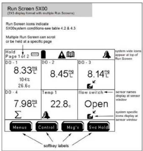
Figure 4.2
Run Screen Icons
Icons identify control, alarm, timer, power, service, and communication information. Icons along the top of the Run Screen indicate 5X00 systemwide conditions - table 4.2. Icons displayed within a sensor window indicate condition(s) specific to that system - table 4.3.
Notes:
- Control icons display when the control relay(s) is active.
- General alarm icon, buzzer, 5X00 emails, and enabled alarm relay(s) [sensor and general alarm] remain active until one of the bottom four 5X00 front panel keys is pressed, regardless if the alarm condition no longer exists.
- Relays, and corresponding icons, that de-energize for Svr Hold, calibration, and/or factory resets are restored after 30 seconds of completing Svr hold, calibration, and/or factory resets. For exceptions, see menu specific information in this chapter.
- With alarms enabled, alarm icons appear at the systemwide location and individual system location regardless if a relay is assigned to the sensor alarm or general alarm system.
| ICONS (systemwide) | Meaning Notes |
 | RS232 communication blinking icon indicates "force serial port" is enabled |
 | TCP/IP communication ethernet module is installed and being used for TCP/IP communication |
| [GS87] | operating in acceptable DC power range |
| [KXAT] | DC power is ≤ low battery trigger |
| [2530] | 5X00 is password protected |
 | sensor (data) logs have information to view logs |
 | one or more control systems is active to view active systems |
| [7BKK] | feed timer is active |
| [CX30] | one or more 10 event timer is active |
| [00D2] | probe timer needs to be reset |
 | General Alarm is active |
table 4.2
Configuring the 5X00
| ICONS (Sensor & Aux) Meaning | Notes |
| sensor system is in alarm | |
| set point control mode low range control relay is energized (to raise sensor value) | |
| set point control mode high range control relay is energized (to lower sensor value) | |
| set point control mode DO low range 2 control relay is energized (to raise sensor value) | |
| set point control mode DO high range 2 control relay is energized (to lower sensor value) | |
| PID/PWM or PID 4/20mA control mode is configured for system |
table 4.3
Menus
5X00 firmware is structured using menus that enable you to easily configure and view system status, messages, and logs. The menu structure and screen formats are very intuitive. Menus are structured in hierarchical fashion. See Appendix 3 "Menu Maps" - beginning on page 225. Example - figure 4.3 illustrates the menu path to configure data logging interval.
Configuring the 5X00
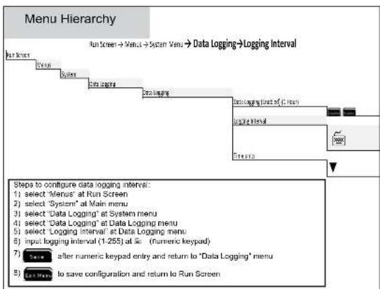
flowchart
graph TD
    A["Start Menu"] --> B["Group"]
    B --> C["Sales"]
    C --> D["Data Logging"]
    D --> E["Data Logging"]
    E --> F["Data Logging List of 1.255 at Main Menu"]
    F --> G["Logging Interval"]
    G --> H["Next Step"]
    H --> I["Next Step"]
    I --> J["Next Step"]
    J --> K["Next Step"]
    K --> L["Next Step"]
    L --> M["Next Step"]
    M --> N["Next Step"]
    N --> O["Next Step"]
    O --> P["Next Step"]
    P --> Q["Next Step"]
    Q --> R["Next Step"]
    R --> S["Next Step"]
    S --> T["Next Step"]
    T --> U["Next Step"]
    U --> V["Next Step"]
    V --> W["Next Step"]
    W --> X["Next Step"]
    X --> Y["Next Step"]
    Y --> Z["Next Step"]
    Z --> AA["Next Step"]
    AA --> AB["Next Step"]
    AB --> AC["Next Step"]
    AC --> AD["Next Step"]
    AD --> AE["Next Step"]
    AE --> AF["Next Step"]
    AF --> AG["Next Step"]
    AG --> AH["Next Step"]
    AH --> AI["Next Step"]
    AI --> AJ["Next Step"]
    AJ --> AK["Next Step"]
    AK --> AL["Next Step"]
    AL --> AM["Next Step"]
    AM --> AN["Next Step"]
    AN --> AO["Next Step"]
    AO --> AP["Next Step"]
    AP --> AQ["Next Step"]
    AQ --> AR["Next Step"]
    AR --> AS["Next Step"]
    AS --> AT["Next Step"]
    AT --> AU["Next Step"]
    AU --> AV["Next Step"]
    AV --> AW["Next Step"]
    AW --> AX["Next Step"]
    AX --> AY["Next Step"]
    AY --> AZ["Next Step"]
    AZ --> BA["Next Step"]
    BA --> BB["Next Step"]
    BB --> BC["Next Step"]
    BC --> BD["Next Step"]
    BD --> BE["Next Step"]
    BE --> BF["Next Step"]
    BF --> BG["Next Step"]
    BG --> BH["Next Step"]
    BH --> BI["Next Step"]
    BI --> BJ["Next Step"]
    BJ --> BK["Next Step"]
    BK --> BL["Next Step"]
    BL --> BM["Next Step"]
    BM --> BN["Next Step"]
    BN --> BO["Next Step"]
    BO --> BP["Next Step"]
    BP --> BQ["Next Step"]
    BQ --> BR["Next Step"]
    BR --> BS["Next Step"]
    BS --> BT["Next Step"]
    BT --> BU["Next Step"]
    BU --> BV["Next Step"]
    BV --> BW["Next Step"]
    BW --> BX["Next Step"]
    BX --> BY["Next Step"]
    BY --> BZ["Next Step"]
Figure 4.3
Configuring the 5X00
Configuring the 5X00
Submenu Screen Types
The 5X00 includes numeric, alpha/numeric, and pull-down submenus - Figure 4.4. See Front panel keys - page 73, to navigate, enter, configure, and view submenus.
5X00 submenu types
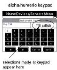


Use 5X00 front panel buttons to navigate, enter, configure, and view submenus

after keypad entry to return to previous menu to save configuration and return to Run Scree
To clear previously entered configuration, scroll and select "clear" and "save" at keypad submenu
Figure 4.4

This symbol indicates that alpha/numeric or numeric keypad entry is required. This symbol is used in the menu map appendix starting on 225 and in directions for menu configuration (this chapter). Use ▲ ▼ front panel keys to scroll and □ to select entries.
The remainder of this chapter provides information on 5X00 menus and submenus and their function. Menu structure and information is provided in hierarchical order starting with the Menus menu. Information on Control and M2G's Svc Hold menus is provided after the Menus menu sections.
Main Menu
Press Men 18 Run Screen to enter the Main Menu.
All system configuration is done through this menu. The four Main Menu submenus are Calibration, System, Sensor Setup, and Timers.
![Main Menu Calibration System Sensor Setup Timers [Call Menu] [ ] [ Back ]](/content/2026/05/935752/images/adcf6426ffc1ee3f2e1e4e9e5a6bc5811f472d43db0a75f4138a8a116ba3c180.jpg)
Calibration Menu
DO sensors(s) must be user calibrated to ensure accurate measurements. Calibrate DO sensors at the Calibration Menu. Entering the Calibration Menu de-energizes control and alarm relays for the DO system being calibrated. Energized DO control relays for systems not being calibrated remain energized including any/all temperature systems regardless if they are the configured temperature (temp) source for the DO sensor being calibrated (5400 only). If necessary, disable any temperature relays for the associated DO sensor in the Sensor Setup menu. There is a 30 second hold off period for control and alarm relays after pressing Cancel or Exit Menu the calibration menu. The hold off period allows sensors time to stabilize before processing readings for controlling and alarming purposes.
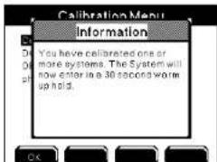
Notes:
- Active Aux and Timer relays do not de-energize at calibration menu.
Configuring the 5X00
- A "Check probe" error message during calibration means that the sensor is unable to calibrate within the 5X00's specifications. This may indicate improper sensor wiring (page 49), 5X00 location (page 27), sensor location or (page 34), the need to service the sensor, or a failed sensor.
- Calibration of temperature sensors is not required and is not available.
- Energized alarm relays for all systems de-energize when a front panel key is pressed to enter the calibration menu. Alarm systems are not reset until Exit Menu is pressed to return the instrument to the run screen.
Getting Ready to Calibrate
Calibrate DO sensor(s) by performing a one point calibration. Calibration can be done to 100% Saturation (Sat) or mg/L. Calibrating to %Sat automatically calibrates to mg/L and vice versa so it is only necessary to calibrate one or the other, not both. For both ease and accuracy, YSI recommends calibrating in %Sat. Salinity compensation for the mg/L readings is obtained from the user entered ppt value. This value can be entered and modified in the DO sensor setup menu.

Figure 4.6 Figure 4.7
Configuring the 5X00
Notes:
- A sensor must be enabled in order to calibrate.
- For YSI 626250 cable/probe assemblies, keep the sensor guard installed during the calibration to protect the membrane from possible physical damage - figure 4.7.
- When calibrating to mg/L, use a ring stand and clamp to secure the sensor in the calibration water sample.
- Older sensors may take longer to calibrate than new ones because the sensor readings may take longer to stabilize.
Calibration Log
Calibration data is stored in the 5X00 calibration log. A calibration data record includes sensor information, the time and date of the calibration, and the calibration method. Press MeG's at the Run Screen to view the calibration log.
Notes:

- Use AquaManager to view and save calibration data on a PC. In addition to the calibration log information listed above, AquaManager calibration logs also include user inputs 1 and 2.
- Information from cancelled calibrations is not stored.
DO
Menus → Calibration → DO
Directions to Calibrate DO Sensor %Sat
- If you have not already done so, locate and install the sensor if using a YSI 5422, see probe installation instructions included with the sensor.
- Next, install a new membrane, or sensor cap, if necessary. See instructions included with membrane kit.

-
Verify that the sensor type and membrane type are configured correctly in the DO Sensor Setup menu at the 5X00.
-
Read Getting Ready to Calibrate - page 82.
-
Verify that the configured salinity (ppt) value in the DO Sensor Setup menu is correct. The entered salinity value should equal the salinity of the water being monitored (not the calibration solution). If necessary, enter the correct the salinity value (ppt).
Menus → Sensor Setup → DO → ppt
- Verify that the local elevation in the DO Sensor Setup menu is correct. If necessary, enter the correct elevation.
Menus → Sensor Setup → DO → Elevation
- Create a 100% water-saturated air environment for the DO sensor:
For a YSI 5520 and 5521 galvanic sensor, there are two options for the %Sat calibration environment:
5400
- Calibrate the galvanic sensor in air by exposing it to air and removing any water droplets from the membrane with a lint free cloth - figure 4.6, 82.
5400
-
If the temperature source for the DO sensor being calibrated is not coming from a temperature sensor located on the DO sensor's probe assembly, make sure that the temperature value being reported by the source is equivalent to the temperature at the DO sensor's calibration location. Menus → Sensor Setup → DO→Temp Source (User Defined)
-
Enter DO calibration menu
Menus → Calibration → DO → Sat
- Allow approximately 10 minutes for the sensor to settle in the calibration environment and for the temperature to equilibrate.
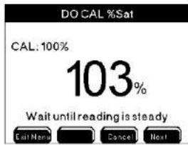
-
After 10 minutes, verify that the DO reading shows no significant change for approximately 30 seconds. Then press Next to complete calibration OR press Cancel to abort the calibration without saving.
-
Press OK to save calibration and return to Run Screen.
- Remove the probe from its calibration chamber.
- Rinse sensor in tap or purified water and place the probe assembly back in its monitoring location.
Directions to Calibrate DO Sensor mg/L
A large bucket can be used when calibrating the DO mg/L reading. Be sure to provide sample flow across the membrane or sensor cap by physically stirring the probe or using a stirrer such as a stir bar.
5400 The DO sensor requires a sample flow rate of at least 3 inches ( 7.62 cm) per second if using the 2.0 mil PE membrane (blue) and at least 6 inches ( 15.24 cm) per second if using the 2.0 mil Teflon membrane (gray).
- If you have not already done so, locate and install the sensor if using a YSI 5422, see probe installation instructions included with the sensor.
- Next, install a new membrane, or sensor cap, if necessary. See instructions included with membrane kit.
5400 3. Verify that the sensor type and membrane type are configured correctly in the DO Sensor Setup menu at the 5X00.
- Read Getting Ready to Calibrate - page 82.
- Verify that the configured salinity (ppt) value in the DO Sensor Setup menu is correct. The entered salinity value should equal the salinity of the water being monitored (not the calibration solution). If necessary, enter the correct the salinity value (ppt).
Menus → Sensor Setup → DO → ppt
- Place the DO probe in a water sample with a known DO concentration (the DO mg/L value can be determined from another recently calibrated DO instrument or from a Winkler titration).
-
If the temperature source for the DO sensor being calibrated is not coming from a temperature sensor located on the DO sensor's probe assembly, make sure that the temperature value being reported by the source is equivalent to the temperature at the DO sensor's calibration location. Menus → Sensor Setup → DO→Temp Source (User Defined)
-
Enter DO calibration menu
Menus → Calibration→ DO→mg/l
9. Allow the probe to stabilize for approximately one minute.
DO CAL mg/L
10.29mg
Wait until reading is steady


- After one minute, verify that the DO value shows no significant change for approximately 30 seconds. Then, press Next to complete the calibration OR press Cancel to escape calibration and return to calibration menu without saving.
Configuring the 5X00

- Using the arrow keys to select numbers on the numeric keypad, enter the known DO value in mg/L. Press ☐ to confirm each number selection.
- Press Save to confirm the entered value OR press Cancel for the calibration without saving any changes.
- Press OK to save the calibration and return to the Run Screen.
- Rinse sensor in tap or purified water and place the probe assembly back in its monitoring location.
- Rinse sensor in tap or purified water and place probe assembly in system stream.
Note:
- Elevation is not required for mg/L Calibration.
Local vs Remote Instruments
NEW A local instrument on a 5X00 network is defined as a 5X00 instrument that is using it's own relay output as a sensor system control or alarm. So, for example if a 5X00 (s/n 55-1111111) General Alarm system is configured to use it's own (5X00 s/n 53-1111111) relay 1 to energize when a general alarm is detected, the relay assignment is considered a local relay configuration. If this same 5X00's (s/n 55-1111111) General Alarm system is configured to use a networked 5500 (s/n 55-2222222) relay 1, the relay configuration is considered a remote relay configuration. IOEM input and IOEM and REM output channels are always considered to be remote configurations because IOEM and REM instruments input and output devices are always configured to a networked 5X00 instrument system. Knowing the difference between local and remote instruments is important since certain menus like 5X00 system and sensor setup menus display local versus remote instrument names differently.
System Menu
Menus → System
The 5400 System Menu contains 18 submenus. The 5500D-01, 5500D-02 and 5500D-04 System Menu contains 19 submenus. Use System submenus to configure non-sensor and non-timer systems. System submenus are shown below. Press
Menus at the Run Screen to enter the Main Menu. Use ▲ ▼ to scroll and highlight a System submenu. Press ← to select and enter a highlighted menu. Configuration changes are saved when Exit Menu is pressed.
5500 "ODO Cal K" submenu appears in 5500D instruments only.
Configuring the 5X00

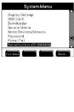
Notes:
See Appendix 3 "Menu Maps" for system defaults and ranges (where applicable) - starting on page 225.
- Menu configurations are saved to the instrument only after Exit Menu is pressed and not when the change is made in the menu. If Exit Menu is not pressed, the changes made to the configuration will not be saved. Exception - Date and time and clear data logs are updated immediately to the system; however, YSI recommends pressing Exit Menu in this instance in order to save any other changes that may have been made to the configuration.
Adjust Contrast
Menus → System → Adjust Contrast
Use the Adjust Contrast menu to lighten or darken the display contrast.

Configuring the 5X00
- Enter Adjust Contrast Menu:
Menus → System → Adjust Contrast
- Use ▲ or ▼ to darken/lighten display.
- Press ← to confirm new display contrast.
- Press Exit Menu to save configuration and return to Run Screen.
Notes:
- The display contrast will adjust automatically based on the 5X00's internal temperature.
- Contrast adjustment cannot be performed using AquaManager.
Buzzer
Menus → System → Buzzer
The 5X00 has an audible buzzer that sounds when a general alarm condition occurs. The buzzer sounds after the alarm hold off period. The General Alarm must be enabled for the buzzer to sound. Use the Buzzer Menu to enable or disable the audible alarm.
When enabled, the buzzer will sound until one of the four bottom softkeys on the 5X00 front panel is pressed. From the Run Screen, press one of the following softkeys
Menus Control Msg's Sve Hold to reset the General Alarm. Resetting the General Alarm silences the buzzer, de-energizes any alarm relay(s), and stops any pending 5X00 email alarm messages. See General Alarm - page 131 and Sensor Setup - page 150 for additional information.

- Enter Buzzer Menu
Menus → System → Buzzer
- Press Disabled or Enabled the buzzer either off or on.
- Press Exit Menu to save configuration and return to Run Screen.
Configuring the 5X00
BackLighting Timer
Menus → System → BackLight Timer
When the backlight timer is enabled, the backlight will turn on when any front panel key is pressed and then turn off after the user configured backlighting timer expires. If the backlight timer is disabled, the display backlight will not turn off.

- Enter BackLight Timer menu Menus -> System ->BackLight Timer
- Use ▲ and ▼ to scroll and highlight submenus.
- Press to select the submenu you wish to change.
- Enable and configure submenus.
- After making desired changes, press Exit Menu to save configuration and return to Run Screen.
Communication
Menus → System → Communications
Select the communication method for AquaManager and/or 5X00 email alarming. Only 1 communication method can be used at a time. Hardware changes are required when the communication method is changed. See Wire Communication Equipment - page 66. Configure remote ethernet communication, network settings, and RS232 settings in the Communications menu.

Configuring the 5X00
Configuring the 5X00
Note:

- AquaManager supports both communication methods.
Email Alarming
Email alarming can be configured 1 of 2 ways.
- A 5X00 email is sent from the 5X00 serial to ethernet device - See Ethernet starting on page 92 for additional information.

- An AquaManager email is sent from the PC running the AquaManager application. AquaManager Autopoller must be running. See Chapter 5 AquaManager - page 197 and AquaManager online help for additional AquaManager email alarming information.
*Ethernet connection requires access to an SMTP server accessible by the local network.
EMAIL ALARMING DISCLAIMER - 'There are many factors that can affect delivery of an email in a timely fashion. Certain SM1P email servers are more reliable than others. No email alarm message has guaranteed delivery. Use multiple email addresses and email forwarding as safe guards. Mechanisms, such as spam filters used by service providers, evolve constantly and can result in non-delivery of email messages. Verify with the service provider and/or network administrator to confirm that the 5X00 communication configuration ensures the most reliable delivery of alarm emails.
Below is a 5X00 DO Alarm Low email sent from a serial to ethernet device. As shown in the example, all of the alarm information is listed in the subject line. The user-configured device name is 'YSI Environmental'. The DO system does not have a user-configured name; therefore, the default system name, 'DO - 3', is included in the subject line.
From: myname@xxx-xxxx.com
Sent: Mon, May 11, 2010 10:24 am
To: myname@xxx-xxxx.com
CC: hot49@xxxx.com
Subject: 05/11/2010 10:23:29 AM YSI Environmental DO - 3 Alarm Low 77%Sat
Notes 5X00 alarm emails:
- 5X00 emails contain date, time, device name, system name, alarm condition, and the sensor reading in the Subject line of the email. When instrument and sensor names are not user configured, the email includes the serial number and default system name, i.e. "DO - 3".
- On a network, user configured instrument and sensor system names appear in the alarm emails for the master only. Slave alarm emails will report the 5X00 slave serial number and the default system names regardless if the names are user configured.
- Aux digital closed alarm is reported as 0.00; aux digital open alarm is reported as 1.00.
- Aux analog alarm emails are reported in 0.00 resolution regardless of the display format resolution.
- See General Alarm- page "General Alarm" on page 131 and Set Points - page 153 for important alarm configuration information.
- Emails are retransmitted based on the Email Retry Delay configuration - 100.
- Separate emails are sent for each alarm condition.
- 5X00 DO email alarms provide the %Sat value and do not provide mg/L value.
- 5X00 emails that say "Alarm Both" mean that both a high and low alarm condition have existed and the alarm has not been cleared by pressing a front panel key.
- 5X00 alarm emails are not transmitted during a service hold.
- 5X00 slave emails are sent to the configured email addresses in the master.
- At power up, the serial to ethernet device may take up to 2 minutes to initialize before sending alarm emails (if alarm condition exists).
- On a network, multiple alarm conditions may exist but only one alarm email is sent. Master alarm emails have priority over slave alarms. When multiple slave alarm conditions exist, it's possible that only one of many 5X00 slave alarms will be sent. Therefore, it is critical that all alarm emails are addressed locally by the user.

Below is an example of a 5X00 DO Alarm Low email sent from AquaManager. All of the information is in the body of the email and not the subject line.
YS15X00 Alarm
ysi environmental (node name in tree)
54-2345567
DO2 Low Alarm: 77
Notes AquaManager alarm emails:
- AquaManager emails are retransmitted based on the Email Retry Delay configuration - page 100.
- Multiple system alarms are included in one AquaManager email.
- AquaManager DO email alarms provide the %Sat value and not the mg/L value.
- For the AquaManager alarm email to function properly, it may be necessary to send a test email to each email address configured in the Email Alarm List in the Node Properties window. Test emails can be sent in the AquaManager Properties window under the Autopoller tab.
Ethernet
Menus → System → Communications → Ethernet
The serial to ethernet device speed and format are self configured at power up (TCP/IP connections). If the serial to ethernet device is not installed or is not installed properly, the ethernet menu will display (Not Available).
Notes:
- 5X00 email alarming from ethernet module requires access to an SMTP server accessible by the local network.
- Do not reconfigure internal serial to ethernet device settings.


- Install serial to ethernet device - page 68.
- The Ethernet icon 📄 displays at the Run Screen when the serial to ethernet device is properly installed.
- Enter Ethernet menu
Menus > System > Communications > Ethernet
- Use ▲ and ▼ to scroll and highlight submenus.
- Press ← to select submenu.
- Configure submenus as needed.
- Press Exit Menu to save configuration and return to Run Screen.
Notes:
The CC/Email address must be configured when using 5X00 email alarming. Specific alarm system information will not be sent if the CC/Email address menu is not configured with a valid email address.

If Autopoller is being used for AquaManager email alarming on a TCP/IP connection, it is strongly recommended that the 5X00 email alarming using the serial to ethernet device be disabled. When the ethernet device sends email alarms, all Autopoller SMS communication is suspended. This could potentially delay any AquaManager alarm emails from being sent.

- To disable the serial to ethernet device from sending alarms, clear all four
email addresses from the Communication → Ethernet menus. Clear the email addresses by using the "Spc" (space) key on the numeric keypad. Save changes at numeric keypad and press Email Menu to save configuration and return to Run Screen.
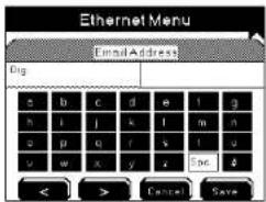
DHCP
Menus → System → Communications → Ethernet → DHCP
Enable DHCP if you are using the serial to ethernet device only for 5X00 email alarming and not for AquaManager remote TCP/IP access.
Notes:
- When DHCP is enabled, the 5X00 IP address is not updated at the IP address menu.
- With DHCP enabled, the serial to ethernet device acquires SMTP and DNS addresses during initialization.

- AquaManager requires a static IP address; therefore, DHCP must be disabled when using AquaManager. Consult the network administrator to obtain a static IP address.
- Power cycle the 5X00 if DHCP configuration changes from disabled to enabled.
IP Address
Menus → System → Communications → Ethernet → IP Address
The IP address can only be configured when DHCP is disabled.
Notes:

- AquaManager users should program the IP Address either by force serial port using AquaManager or locally at the 5X00. Poll node using RS232 communication. Next upload configuration information including: static IP, port, subnet, and gateway addresses.
- When DHCP is enabled, the IP address is not updated at the IP address menu.
- Power cycle the 5X00 whenever a new IP address is configured.
- Numbers between 0-255 are valid for each of the four (4) IP Address fields.
Subnet Mask
Menus → System → Communications → Ethernet → Subnet Mask
A Subnet mask address can only be configured when DHCP is disabled. The subnet mask number helps to define the relationship between the host (computers, routers, switches, etc.) and the rest of the network. Consult the network administrator when configuring this menu.
Notes:
When DHCP is enabled, the Subnet Mask address is not updated at the Subnet Mask menu.

AquaManager users should program the Subnet mask either by force serial port using AquaManager or locally at the 5X00. Poll node using RS232 communication. Next upload configuration information including: static IP, port, subnet, and gateway addresses.
- Numbers between 0-255 are valid for each of the four (4) Subnet Mask IP Address fields.
Gateway
Menus → System → Communications → Ethernet → Gateway
The Gateway address can only be configured when DHCP is disabled. A gateway IP refers to a device on a network which sends local network traffic to other networks. Consult the network administrator when configuring this menu.
Notes:
When DHCP is enabled, the Gateway address is not updated at the Gateway menu.

- AquaManager users should program the Gateway address either by force serial port using AquaManager or locally at the 5X00. Poll node using RS232 communication. Next upload configuration information including: static IP, port, subnet, and gateway addresses.
Numbers between 0-255 are valid for each of the four (4) Gateway IP Address fields.
Port
Menus → System → Communications → Ethernet → Port
The default port number for the ethernet module is 10001. Consult the network administrator when configuring this menu.
Note:

AquaManager users should program the port number either by force serial port using AquaManager or locally at the 5X00. Poll node using RS232 communication. Next upload configuration information including: static IP, port, subnet, and gateway addresses.
DNS Address
Menus → System → Communications → Ethernet → DNS
Domain Name Service (DNS) refers to the server, or workstation, used to convert domain names into IP addresses.
Notes:
- With DHCP enabled, the serial to ethernet device will acquire SMTP and DNS addresses during initialization.
- When DHCP is enabled, the DNS address is not updated at the IP address menu.
- Numbers between 0-255 are valid for each of the four (4) DNS IP Address fields.
Email Addresses
Menus → System → Communications → Ethernet → Email Address
| → | |
| → | |
| → | CC/Email |
Addres Addres
Ad
Up to four email addresses can be configured for 5X00 emails. At a minimum, the first email address and the CC/email address must be configured. If the CC/email address is not configured, 5X00 email alarms will contain no alarm information. The email 'from' address will be the email address entered in the first Email Address menu.
Notes:
See Send Test Email Msg - 99 to verify proper configuration of ethernet menus.
- On a network, both master and slave alarm emails are sent to the configured email addresses in the master.
- Test the alarm email delivery by creating an alarm condition at the 5X00 and verify the email(s) is received.


- The CC/Email address must be configured when using 5X00 email alarming. Specific alarm system information will not be sent if the CC/Email address menu is not configured with a valid email address.
- Use AquaManager to easily configure email addresses using the PC keyboard. See AquaManager on line help for additional information.
- If Autopoller is being used for AquaManager email alarming on a TCP/IP connection, it is strongly recommended that the 5X00 email alarming using the serial to ethernet device be disabled. When the ethernet device sends email alarms, all Autopoller SMS communication is suspended. This could potentially delay any AquaManager alarm emails from being sent.
- To disable the serial to ethernet device from sending alarms, clear all four email addresses from the Communication → Ethernet menus. Clear the email addresses by using the "Spc" (space) key on the numeric keypad. Save change
at numeric keypad and press Escal Menu to save configuration and return to Run Screen.
Ethernet Module Error Message
At power up, the serial to ethernet device will generate an error message if it cannot properly handshake with the 5X00 hardware. If this error occurs, communication (AquaManager and 5X00 alarm emails) will not work via TCP/IP. The error could be a result of incorrect serial to ethernet device installation or a faulty ethernet device. The error message will appear in the event log.

SMS Messaging with Ethernet Module
SMS (Short Message Service) or text messaging is a service for sending messages to your cell phone or mobile device. To use SMS messaging, enter the email address in the Menus → System → Communications → Ethernet → Email address. See Appendix 6 SMS - page 255 for a list of cellular and mobile companies that support sending text messages.
Node Network
Menus → System → Communications → Network
A node network refers to either one stand alone master node and/or one master node and up to 31 configured and wired slave nodes. Node networks with at least one slave are physically connected using RS485 protocol see 60 for additional information. Only the master node is configured for serial or ethernet module communication.
On a network with at least one slave the master continuously queries enabled slaves on the network. The master is the access point for the entire network. This includes AquaManager communication and sending of 5200A/5X00 alarm emails. Slave nodes must be configured with a slave address.
Note:

- Multiple node networks communicating via direct connect (RS232) require separate PC COM ports for simultaneous AquaManager mapping and autopolling.
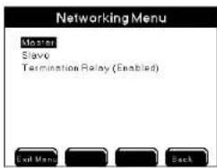
-
Wire 5X00 network - page 60.
-
Enter Network menu
Menus → System → Communications → Network
-
Press ▲ and ▼ to scroll and highlight submenus.
-
For master node: Press ← at master submenu.
-
For all slave nodes: Press at slave submenu. Configure a slave address.

Note: - The slave address appears as the slave subnode at node properties. - Configure slave addresses with numbers of 1 through 31.
- Disable the Termination Relay on all devices except the first and last device on the network. Menus → System → Communications → Network → Termination Relay.
Configuring the 5X00
-
Verify that the Termination Relay is enabled on the first and last device on the network.
-
For master node: Press at master submenu. At assign slaves menu, select the slave address configured in step 5 above. Press enter. Enable one slave at a time using Disabled Enabled softkeys.

-
Press to Enter Menu configuration and return to Run Screen.
-
Each slave should be tested one by one. Insert network termination strip and apply power to the master and the last physical device on the network. If the master is not the first or last physical device on the network, apply power and insert network terminal strip on the master and on the first and last physical devices on the network. Refer to network wiring instructions for additional information - page 60. Testing for proper wiring and configuration can be done one of two ways:
A. After performing step 9, wait at least 30 seconds and then reenter the Communication Master submenu. If serial number of the slave is displayed next to the slave address number, the communication network is wired and configured correctly.

Configuring the 5X00

B. After performing step 9, wait at least 30 seconds and then poll the slave node using Aqua Manager. Follow AquaManager online Help to Insert node into AquaManager network. AquaManager will obtain node configuration, current data and any logs if the node network is wired and configured correctly.
Notes:
- An Event and General Alarm (if enabled) will occur if, after ten queries, an enabled slave does not respond to the Master.

- Configuring a 5X00 as a Master overrides any slave configuration that had been previously saved.
- Slave alarms (slave alarm at master and 5X00 email alarms) will not occur if slave node serial number is not recognized at master node at steps 10. A or 10. B above.
Termination Relay
Menus → System → Communications → Network → Termination Relay
The termination relay must be enabled on the first and last 5X00 on a network. All other devices should have the termination relay disabled.
Send Test Email Msg
Menus → System → Communications → Send Test Email Msg
Send a test email to verify proper configuration of ethernet menus. If necessary confirm all ethernet menus configuration starting on page 92. Test emails are only transmitted from configured master 5X00s.
Notes:
- Test emails are sent to all configured email address.
- Exit to Run Screen is required before the test email is sent.
Example of a 5X00 test email sent from ethernet device:
From: myname@xxx-xxxx.com
Sent: Wed, Feb 04, 2010 3:49 pm
To: myname@xxx-xxxx.com
CC: sweet49@xxxx.com
Subject: 02/04/10 03:50:05 PM YSI5X00 Email Alarm Test Message
Email Retry Delay
Menus → System → Communications → Email Retry Delay
Configure the Email Retry Delay for the time interval that emails should be retransmitted after the initial alarm email is sent. The initial alarm email is sent immediately after the general alarm hold off time or after the aux hold off time. Emails will be retransmitted until one of the front panel softkeys is pressed, regardless if the alarm condition still exists.
Notes:
- On a network, emails are retransmitted according to the slave retry delay configuration of the slave in alarm and not the master's email retry delay configuration. Please note, a slave Email Retry Delay menu will display (Not available) because of its slave configuration; however, this feature is available and has a default value of 15 minutes that can be configured by the user.
- The Retry Delay should be configured at intervals ≥ 15 minutes.
- AquaManager alarm emails are retransmitted based on 5X00 slave(s) and master email retry delay configuration.

Baud Rate RS232
Menus → System → Communications → Baud Rate
Configure the Baud rate (for RS232 connections only) in the 5X00 to match the baud rate configured in AquaManager. Use the default rate of 115200 for fastest communication speed.
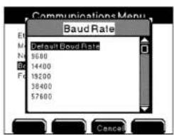
- Enter Network menu
Menus → System → Communications → Network → Baud Rate
- Press ▲ or ▼ to scroll and highlight a selection.
- Press ← to confirm selection.
- Press Exit Menu to save configuration and return to Run Screen.
Force Serial Port
Menus → System → Communications → Force Serial Port
Enable the Force Serial Port when the 5X00 is communicating via RS232 (direct) to a PC and when the 5X00 has a serial to ethernet device.
Communications Menu
Ethernet (Not Available)
Network (Master)
Send Text Email Mag (Not Available)
Email Retry Delay (Not Available)
Time Units (Not Available)
Boud Rate (115200)
Force Serial Port (Disabled)


- Wire RS232 connection - page 66.
- Enter Communications menu
Menus → System → Communications → Force Serial Port
- Use the Disabled Enabled softkeys to configure off or on.
- Press Exit Menu to save configuration and return to Run Screen.
Notes:
- RS232 connection is required to upload firmware using the Firmware Up-dater.
- The RS232 icon 📄 blinks at the Run Screen when in Force Serial Port mode.
Non-Networked (Stand Alone) 5X00s
Non-networked (stand alone) 5X00s must have the termination relay enabled. In addition, non-networked (stand alone) 5X00s must be configured as a master in the System Communication menu with no slave nodes enabled.
Configure AUX
Menus → System → Configure Aux 1-6
The 5X00 has six auxiliary (Aux) inputs. Aux inputs 1, 2, 3, 4, 5, and 6 can be configured for digital or analog (0-1V, DC 0-5VDC, or 4-20 mA) inputs. In addition, Aux 3, 4, 5, and 6 can be configured with a temperature sensor. Configure suffix, minimum (Min), maximum (Max), Input Scale Min, Input Scale Max and display format menus for non temperature analog inputs. To configure set points, control, alarms and relays see specific sensor set up menus. See Aux digital sensor set up - page 165. See Aux analog (non temperature) sensor set up - page 166. See Aux and ODO temperature sensor set up - page 168. Configure Aux menus vary based on the configured Input Type.
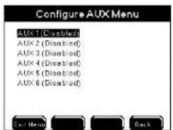

5400 Configure Aux 5 menu (no Temp Source menu)

5500 Configure Aux 5 menu
(Temp Source menu will be available when Temperature Input Type
Probe Name
Menus → System → Configure Aux →Aux 1-6→Probe Name
Use the alpha/numeric keypad to name aux inputs. Configured name(s) appear throughout menus and at Run Screen - figure 4.7- page 106.
Note:
Aux names can also be configured at Menus → System → Name Devices/Sensors.
Input Type
Menus → System → Configure Aux →Aux 1-6→Input Type →Digital
→0-1v
→0-5v
→4/20ma
→Aux 3-6→Input Type →Temperature
Select the input type for the device(s) wired to aux system(s). Aux Sensor Setup menu selections are based on the aux input type configured at system>Configure Aux menu. All input types are discussed in the following sections.

Digital
Menus → System → Configure Aux → Aux 1-6→Input Type→Digital
Use digital input when wiring an external device to control or alarm when the contacts of an external switch open or close. A common application would be to detect high or low water levels using a float switch.
Notes:
- Suffix, Min, Max, and Display Format are not available for digital inputs. - In the 5X00 sensor log, aux digital "closed" is logged as Aux 0.00. Aux digital "open" is logged as Aux 1.00.
Directions to configure Digital device at Configure Aux menu:
- Wire aux digital devices - page 57.
- Enter Aux menu
Menus → System → Configure Aux →Aux 1-6
- Use ▲ and ▼ to scroll and highlight submenus.
- Press to select.
- Configure digital input type and name.
- Press Exit Menu to save configuration and return to Run Screen.
Configuring the 5X00
- Go to Sensor Setup Menus → Sensor Setup Aux 1-6 - page 165 to enable and configure control/alarm on condition, control/alarm relay, and hold off time.
- Press Exit Menu to save configuration.
0-1VDC and 0-5VDC and 4/20mA
Menus → System → Configure Aux →Aux 1-6→Input Type →0-1V
$$ \rightarrow 0 - 5 \mathrm{V} $$
$$ \rightarrow 4 / 2 0 \mathrm{ma} $$
Select the analog input type based on the signal being sent from the device. Notes:
- It is normal to hear an on-board relay "click" when switching to or from the 4/20ma aux input type.
- Analog systems will not monitor, control, or alarm properly if a device that operates outside the configured analog range is installed and configured.
Suffix
Menus → System → Configure Aux →Aux 1-6→Suffix
Enter the Suffix (up to 4 characters) to describe the input type or units. The suffix is displayed at the Run Screen. The suffix is typically used to describe the input signal type.
Example - when using a total dissolved gas pressure sensor "mmHg" could be used as a suffix for measuring TGP (total dissolved gas pressure) - figure 4.7 - page 106.
Min and Max values
Menus → System → Configure Aux → Aux 1-6 → Min → Max
Min and Max values are user defined. The range is -10000 to 10000. Min and Max values scale the display output value. The min and max values may be configured to correspond to the minimum input level (i.e. 0VDC or 4mA) and maximum input level (i.e. 1VDC, 5VDC, or 20mA). The Min value must be less than Max value.
Example - when using a total dissolved gas pressure sensor (0-5VDC input type) enter -400 for min value. The 5X00 will display “-400” when the input value is 0VDC. Configure the max value to correspond to the maximum input value as +400. The 5X00 will display “400” when input value is 5VDC.
Configuring the 5X00
Notes:
- The 5X00 will monitor and data log based on the "min" and "max" voltage or current signal.
- To enter negative values, type the whole number then select “-” on the numeric keypad.
- Whenever min and/or max values are changed, go to Menus → System → Sensor Setup → Aux 1-6 → Control Low and Control High menu to verify control/alarm values are correct for the application.
Input Scale Min and Max values
Menus → System → Configure Aux →Aux 1-6 →Input Scale Min →Input Scale Max
Input scaling allows a way to view data within a specific input range of the input type (0-1v, 0-5v, 420/ma) in greater resolution. In the below example 0-1v is the input type and display format = 0. The configured Min value is 0, and the configured Max value is 1000. The input scale Min is .25 and the input scale Max is .75. (The user wants to only view data within this specific range). In the below example an input value of .25v = a display and datalog value of 0. An input value of .50v = a display value and datalog value of 1000.

Display Format
Menus → System → Configure Aux →Aux 1-6→Display Format
Configure the Display format (0, 0.0, or 0.00) based on the resolution to be displayed at the Run Screen.
Example - when using a total dissolved gas pressure sensor, configure the display format as 0.0 - figure 4.7 below.
In the below screen shot, the Run Screen is displaying aux name "TGP," suffix "mmHg," with display format "0.0". The display value represents an input of 1.875 volts with 0-5VDC analog aux configuration. The min value = "-400". The max value = "+400." The control/alarm low is "-50." Alarms are enabled for this aux input.

figure 4.7
Notes:
- Values displayed at the run screen are based on display format resolution configuration. Example - if the display format is 0.0 and the min value input is 1.88, then 1.9 will be displayed at the run screen.
- 5X00 aux analog (non temp) sensor log records 0.00 resolution regardless of the selected resolution in the aux analog display format configuration.
Directions to configure Aux analog (non temp) Configure Aux menu:
- Wire aux analog devices - page 57.
- Enter Aux menu
Menus → System → Configure Aux → Aux 1-6
- Use ▲ and ▼ to scroll and highlight submenus.
- Press ← to select.
- Press Exit Menu to save configuration.
- Go to Sensor Setup Menus → Sensor Setup Aux 1-6 - page 166. to en-
able and configure set points, control, alarm, relays, and hold off time.
- Press Exit Menu to save configuration.
Note:
The alarm low value must be ≥ the min value. The alarm high value must be ≤ the max value.
Analog Temperature (Aux 3, 4, 5 and 6)
Menus → System → Configure Aux →Aux 3-6→Input Type→Temperature
Aux 3, 4, 5 and 6 can be wired and configured for a temperature sensor. Temperature systems are configured differently for 5400 and 5500D instruments. The differences are explained below.
5400 5400 \~ Aux configured temperature systems can be configured as stand alone independent temperature systems. In addition, Aux temperature systems can be configured as the temperature source for any of the four DO systems. Configure the DO temperature source in the DO sensor set up menu - page 173.
5500550000D-01, 5500D-02 and 5500D-04 \~ Aux configured temperature systems can only be configured as stand alone independent temperature systems and cannot be assigned as a temperature compensation source for any DO system. The DO system temperature compensation value is always taken from the temperature sensor in the ODO probe. Temperature systems can be configured using the ODO temperature value or the Aux 3, 4, 5 and/or 6 temperature value. Configure the temperature system source at the Menus > System > Configure Aux >Temp Source menu. Configure "Aux Port" if the temperature system is to be driven by the input value of a temperature sensor wired to aux 3, 4, 5 or 6. Configure "ODO Probe" if the temperature system is to be driven by the ODO probe temperature sensor value.

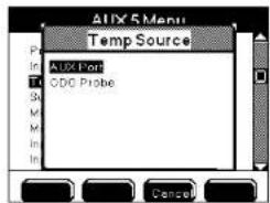
Directions to configure Aux temperature Configure Aux menu:
- Wire temperature sensors - page 52.
Configuring the 5X00
- Enter Aux menu
Menus → System → Configure Aux → Aux 3-6
-
Configure temperature input type and name.
-
Use ▲ ▼ to scroll and highlight submenus.
-
Press ← to select.
-
Press Exit Menu to save settings and return to Run Screen.
-
Go to Sensor Setup Menus → Sensor Setup Temperature for Aux 3-6 and ODO - 168 to configure temperature system.
-
Press Exit Menu to save settings and return to Run Screen.
Note:
- The Sensor Setup menu - page 150 is automatically enabled when an aux channel is configured for temperature.
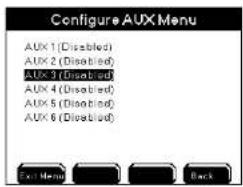

Configure E-AUX
NEW Menus → System → Configure E-Aux 1-8
All 5X00 instruments have eight E-Aux systems. E-Aux systems are sometimes referred to as virtual system because unlike Aux systems which use six onboard (Aux) inputs for wiring input devices, E-Aux systems use inputs that are wired to a networked IOEM. 5X00 E-Aux systems mimic aux systems but use a remote IOEM wiring location for the actual input. E-Aux inputs 1-8 can be configured for digital, analog (0-1V, DC 0-5VDC, or 4-20 mA) or temperature inputs. System → Configure E-Aux 1-8 menu selections change based on input type selection. Configure suffix, minimum (Min), maximum (Max), Input Scale Min, Input Scale Max and display format menus for non temperature analog inputs. To configure setpoints, control, alarms and relays see specific sensor setup menus for configured input type For E-Aux Analog Sensor Setup - page 166. For E-Aux Temperature Sensor Setup - page 168. For E-Aux Digital Sensor Setup - page 165.
Configuring the 5X00
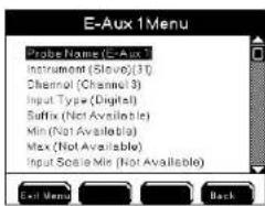

Notes:
- Configure E-Aux systems to monitor, control and/or alarm IOEM inputs the same way 5X00 aux sensor systems function.
- E-Aux systems have data and event logging functionality.
- E-Aux system datalogs are not visible at the instrument.
At the Run Screen "Offline" display at an E-Aux system means the configured IOEM input value that the associated 5X00 instrument E-Aux system is configured for is not recognized. An example - if an IOEM channel mode is configured to digital and the input signal is a 0-1V signal, the reading at the run screen will be "Offline";

Probe Name
Menus → System → Configure E-Aux → E-Aux 1-8 → Probe Name
Use the alpha/numeric keypad to name E-Aux inputs. Configured name(s) appear throughout menus and at Run Screen - figure 4.7- page 106.
Note:
- E-Aux names can also be configured at Menus → System → Name Devices/Sensors>Name E-Aux>E-Aux 1-8.
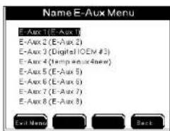
Instrument
Menus → System → Configure E-Aux →E-Aux 1-8→Instrument>Device Address menu opens
Select the IOEM slave device address whose input will be used as an input signal for this E-Aux system.
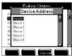
- Use ▲ ▼ to scroll and highlight IOEM Slave device address.
- Press ← to select.
- Press Exit Menu to save settings and return to Run Screen.
Notes:
The Device Address menu displays a generic list of instruments being Master and Slaves 1-31.
- The Local Machine user configured name is displayed if the local machine is configured.
- See page 86 for local versus remote instrument description.
- The Device Address menu will always display a Master and slaves 1-31 regardless of the actual number of slaves wired to the node network.
Channel
Menus → System → Configure E-Aux → E-Aux 1-8 → Channel > Channel menu opens
Select the IOEM channel whose wired input location will be used as an input signal for this E-Aux system.

- Use ▲ ▼ to scroll and highlight IOEM channels.
- Press to select.
- Press Exit Menu to save settings and return to Run Screen.
Notes:
- The Channel menu displays a generic list of instruments being Channel 1-8.
- The Channel menu will always display Channels 1-8 regardless if the IOEM device selected is an IOEM-4 which has only 4 channels and not 8.
- IOEM channel modes can only be configured using AquaManager. See AquaManager online help for directions to configure IOEM channel input mode (digital, 0-1V, 0-5V, 4mA-20mA, temperature);
Input Type
Menus → System → Configure E-Aux → E-Aux 1-8 → Input Type → Digital
Select the input type for the device(s) wired to IOEM channel(s). E-Aux Sensor Setup menu selections are based on the E-Aux input type configured at system>E-Aux menu. Input types are discussed in the following sections.
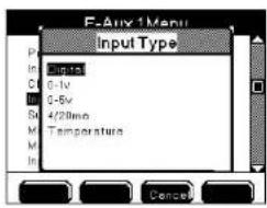
Digital

Use digital input when wiring an external device to an IOEM channel that will control or alarm when the contacts of an external switch open or close. A common application would be to detect high or low water levels using a float switch.
Notes:
- Suffix, Min, Max, and Display Format are not available for digital inputs.
- In the 5X00 sensor log, aux digital "closed" is logged as Aux 0.00. Aux digital "open" is logged as Aux 1.00.

- IOEM input channel modes can only be configured using AquaManager. See AquaManager online help for directions to configure IOEM channel input mode (digital, 0-1V, 0-5V, 4mA-20mA, temperature);
Configure E-Aux Digital - Configure E-Aux system menu:
- Wire E-aux digital devices - see IOEM Safety and Installation Guide>Chapter 3 Installation and Wiring>IOEM input configuration>Wire digital input.
- Refer to and follow directions at IOEM Safety and Installation Guide>Chapter 4>Quick Start - IOEM Configuration to confirm correct network connectivity;
- Follow directions in the Quick Start section to configure IOEM channel mode to digital.
-
Enter E-Aux menu Menus → System → Configure E-Aux → E-Aux 1-8
-
Use ▲ and ▼ to scroll and select submenus.
- Press ← to select.
- Configure input type to digital - page 111, name - page 109, instrument - page 110 and channel - page 111.
- Press Exit Menu to save configuration and return to Run Screen.
- Go to Sensor Setup Menus → Sensor Setup E-Aux 1-8 - page 165 to enable and configure control/alarm on condition, control/alarm relay, and hold off time.
- Press Exit Menu to save configuration.
Analog
0-1VDC and 0-5VDC and 4/20mA
Menus → System → Configure E-Aux → E-Aux 1-9 → Input Type → 0-1V → 0-5V → 4/20ma
Select the analog input type based on the signal being sent from the device wired at the IOEM channel.
![E-Aux 1Menu Probe Name (C-Aux) Instrument (Motor) Channel (Channel1) Input Type (4/20ms) Suffix Min (0.00) Max (1.00) Input Scale Mix [4.00] Exit Menu Back](/content/2026/05/935752/images/a4ba54fb92ee458153d0598856cad7c6274481ac6509f08eb3ffe31863d03ed4.jpg)
![E-Aux 1 Menu Channel [Channel1] Input Type (4/20 mo) Suffix Min (0.00) Max (1.00) Input Scale Min (4.00) Input Scale Max (20.00) Display Format (0.00) Exit Menu Back](/content/2026/05/935752/images/2322afa54fd37c64b123c65c76b7fe8def41c217f93a9b4f2b84ed2cde03a2d4.jpg)
Notes:
- It is normal to hear an on-board relay "click" when switching to or from the 4/20ma E-aux input type.
- Analog systems will not monitor, control, or alarm properly if a device that operates outside the configured analog range is installed and configured.
Suffix
Menus → System → Configure E-Aux → E-Aux 1-8→Suffix
Enter the Suffix (up to 4 characters) to describe the input type or units. The suffix is displayed at the Run Screen. The suffix is typically used to describe the input signal type.
Example - when using a total dissolved gas pressure sensor "mmHg" could be used as a suffix for measuring TGP (total dissolved gas pressure) - figure 4.7 - page 115.
Min and Max values
Menus → System → Configure E-Aux → E-Aux 1-8 → Min → Max
Min and Max values are user defined. The range is -10000 to 10000. Min and Max values scale the display output value. The min and max values may be configured to correspond to the minimum input level (i.e. 0VDC or 4mA) and maximum input level (i.e. 1VDC, 5VDC, or 20mA). The Min value must be less than Max value.
Example - when using a total dissolved gas pressure sensor (0-5VDC input type) enter -400 for min value. The 5X00 will display “-400” when the input value is 0VDC. Configure the max value to correspond to the maximum input value as +400. The 5X00 will display “400” when input value is 5VDC.
Notes:
- The 5X00 will monitor and data log based on the "min" and "max" voltage or current signal.
- To enter negative values, type the whole number then select "-" on the numeric keypad.
- Whenever min and/or max values are changed, go to Menus → System → Sensor Setup → E-Aux 1-6 → Control Low and Control High menus to verify control/alarm values are correct for the application.
Input Scale Min and Max values
Menus → System → Configure E-Aux → E-Aux 1-8 → Input Scale Min → Input Scale Max
Input scaling allows a way to view data within a specific input range of the input type (0-1v, 0-5v, 420/ma) in greater resolution. In the below example 0-1v is the input type and display format = 0. The configured Min value is 0, and the configured Max value is 1000. The input scale Min is .25 and the input scale Max is .75. (The user wants to only view data within this specific range). In the below example an input value of .25v = a display and datalog value of 0. An input value of .50v = a display value and datalog value of 1000.

Display Format
Menus → System → Configure E-Aux → E-Aux 1-8 → Display Format
Configure the Display format (0, 0.0, or 0.00) based on the resolution to be displayed at the Run Screen.
Example - when using a total dissolved gas pressure sensor, configure the display format as 0.0 - figure 4.7 below.
In the below screen shot, the Run Screen is displaying aux name "TGP," suffix "mmHg," with display format "0.0". The display value represents an input of 1.875 volts with 0-5VDC analog aux configuration. The min value = "-400". The max value = "+400." The control/alarm low is "-50." Alarms are enabled for this aux input.

figure 4.7
Notes:
- Values displayed at the run screen are based on display format resolution configuration. Example - if the display format is 0.0 and the min value input is 1.88, then 1.9 will be displayed at the run screen.
- 5X00 aux analog (non temp) sensor log records 0.00 resolution regardless of the selected resolution in the aux analog display format configuration.
Configure E-Aux analog - Configure E-Aux system menu:
- Wire E-Aux analog device - see IOEM Safety and Installation Guide>Chapter 3 Installation and Wiring>IOEM input configuration>Wire analog input.
- Refer to and follow directions at IOEM Safety and Installation Guide>Chapter 4>Quick Start - IOEM Configuration to confirm correct network connectivity;
- Follow directions in the Quick Start section to configure IOEM channel mode to 0-1v, 0-5v or 4/20mA.
- Enter E-Aux menu
Menus → System → Configure E-Aux → E-Aux 1-8
- Use ▲ and ▼ to scroll and highlight submenus to configure.
- Press to select.
-
Configure Analog system name - page 109, instrument - page 110, channel - page 111, input type - page 111, suffix - page 113, min/max - page 114, scale min/scale max -page 114 and display format -page 115 menus. E-Aux submenus configuration is described in the above sections.
-
Press Exit Menu to save configuration.
-
Go to Sensor Setup Menus → Sensor Setup E-Aux 1-8 - page 166 to enable and configure set points, control, alarm, relays, and hold off time.
- Press Exit Menu to save configuration.
Note:
The alarm low value must be ≥ the min value. The alarm high value must be ≤ the max value.
Temperature
Menus → System → Configure E-Aux → E-Aux 3-6 → Input Type → Temperature

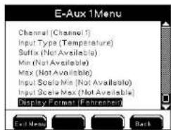
Configure E-Aux temperature Configure E-Aux system menu:
- Wire temperature device - see IOEM Safety and Installation Guide>Chapter 3 Installation and Wiring>IOEM input configuration>Wire temperature input.
- Refer to and follow directions at IOEM Safety and Installation Guide>Chapter 4>Quick Start - IOEM Configuration to confirm correct network connectivity;
- Follow directions in the Quick Start section to configure IOEM channel mode to temperature.
- Enter E-Aux menu
Menus → System → Configure E-Aux → E-Aux 1-8
- Use ▲ and ▼ to scroll and highlight submenus to configure.
- Press to select.
- Configure name- see page 109 instrument - page 110, channel - page 111, input type - page 111 and display format ( F^o or C^o ).
- Press Exit Menu to save configuration.
- Go to Sensor Setup Menus → Sensor Setup E-Aux 1-8 - page 168 to enable and configure set points, control, alarm, relays, and hold off time.
- Press Exit Menu to save configuration.
Data Logging
Menus → System → Data Logging
Msg's
The 5X00 saves information in calibration, sensor, and event logs. Press at the Run Screen to view the 25 most recent records for each log. The 5X00 sensor log stores 2000 records. The calibration log can store 500 records. And the event log stores 1250 records. Once a 5X00 log is full, it will begin overwriting the oldest records with new records (data wrapping).
![Data Logging Menu Data Logging (Enabled) [Hours] Event Logging (Enabled) Clear Logs Exit Menu Back](/content/2026/05/935752/images/9ef8f65b465119ade974c21f3994c45fc13314c36250175d8676dd85ed80d53f.jpg)
Notes:
- Use AquaManager to store and analyze 5X00 logs. To avoid gaps in data, use polling intervals based on the user defined data logging configuration. Set the data log interval so that analyzing the data is meaningful.
- AquaManager users can view Configuration events in the Configuration log. Configuration events are created when certain 5X00 configuration changes are made. The configuration log is not accessible at the 5X00. See AquaManager Online Help for additional information.
Data Logging
Menus → System → Data Logging → Data Logging
The 5X00 sensor log stores records for sensors and aux systems. Sensor logs are time and date stamped based on the user configured logging interval (10-255 seconds or 1-255 minutes or hours).
- Enter Data Logging menu
Menus → System → Data Logging → Data Logging
- Use ▲ ▼ to scroll and highlight submenus.
- Press ← to select.
- Enable and configure submenus.
- Press End Menu to save setting and return to Run Screen.
Press Msg's to view the 25 most recent sensor logs
Notes:
- Aux digital "closed" is logged as Aux 0.00. Aux digital "open" is logged as Aux 1.00.
- The 5X00 sensor log records 0.00 resolution for aux analog inputs regardless of the selected display format.
- DO values are stored in mg/l & %Sat regardless of selected display format.


- Sensor logs record the default system name and not the user configured system name.
- Aux temperature values are not accessible at the 5X00. Temperature values can only be obtained using AquaManager. Values will be shown in the AquaManager data log in °C regardless of the selected display format.
- E-Aux system datalogs are not visible at the instrument. E-Aux system datalogs are only viewable using AquaManager.
- Aux Temperature values are only available and stored for temperature systems assigned to a DO system. These values are not available at the 5400. The values can only be viewed with AquaManager.
- Temperature values are available for either a ODO temperature sensor or a stand alone aux temperature systems. These values are not available at the 5500. The values can only be viewed with AquaManager.
- Changes to the data logging interval take effect after the expiration of the interval being changed. Example - if the interval is changed from one hour to one minute, one minute logging will begin after the expiration of the current one hour interval. Power cycle the 5X00 to make a change to the data logging interval occur immediately.
- Menu configurations are saved to the system by pressing Exit Menu to return to the Run Screen and not when the change is made in the menu. Exception - Date and time and clear data logs are updated immediately to the system, not when Exit Menu is pressed.
- The sensor log contains values for all sensor and aux systems regardless if the system is disabled.
- 5X00 sensor log values for disabled systems and systems without sensors are not valid.
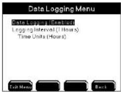
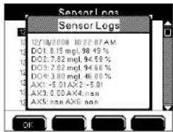
In the above sensor log screen shot Aux 3 is assigned as temperature for DO 1. DO 4 and Aux 1, 2, 4, 5, & 6 are disabled.
Event Logging
Menus → System → Data Logging → Event Logging
Control, Alarm, and Timer relays assigned to 5X00 systems create events when they turn on and off. In addition, AC power failures, ethernet device error messages, and slave network failures create events. These events are stored in the Event Log. Event logs identify the 5X00 system, are time and date stamped, and record relay action ("on" or "off").
- Enter Event Logging menu
Menus → System → Data Logging → Event Logging
-
Use ▲ ▼ to scroll and highlight submenus.
-
Press ← to select.
-
Press Disabled Enabled to turn off or on.
-
Press Exit Menu to save setting and return to Run Screen.
Press Mac's to view 25 most recent event logs.
Press Control to view active ("on") non timer events. See Control Menu - 192 for additional information.
Notes:
- The General Alarm does not create an event whether a general alarm relay is enabled or not.
- Events are not recorded when relays de-energize due to system-wide events. System-wide events include calibration, Svr Hold, factory resets, power cycle, 30 second sensor system reset, relay test, and disabling systems.
- Event logs record the default system name not user configured system name.
- Event logs do not record relay number or user configured relay name.
- Aux digital events will never display "alarm" regardless if alarms are enabled, see below screen shot on right.
- E-Aux system event logs are stored at the local instrument whose E-Aux system is being used and not at the device whose output is creating the event. For example - if an OEM channel 2, whose slave address is 4, is configured as an E-Aux temperature input for a 5200A (slave 14), and a low temperature control relay output for this slave 14 is configured to a 5500 (master), the 5200A (slave 14) and not the master 5500 records the low temperature control events.
Clear Logs
Menus → System → Data Logging → Clear Logs
Use the Clear Log option to permanently delete all event and/or sensor log records from the 5X00.
Before permanently deleting sensor and event logs, poll all data using AquaManager. AquaManager will store all logs in PC database.

- Enter Clear Log menu
Menus → System → Data Logging → Clear Logs
-
Use ▲ and ▼ to scroll submenu.
-
Press to select.
-
The instrument will prompt, "Are You Sure?" Press one of the following softkeys to confirm: Yes No Cancel.
-
Selecting "Yes" deletes logs after approximately three seconds.
-
Selecting "No" or "Cancel" does not delete logs and returns to the Data Logging menu.
-
Press Exit Menu to save setting and return to Run Screen.
Notes:
- Logs cannot be deleted from the 5X00 instrument using AquaManager. - Calibration and Configuration logs cannot be cleared from 5X00.
- Clear data logs are updated immediately to the system and not when Exit Menu
is pressed. YSI recommends pressing Exit Menu in this instance in order to save any other changes that may have been made to the configuration. Exception -
Date/Time
Menus → System → Date/Time
It is important to configure the correct date and time in the 5X00. Four 10-event daily timers and four feed timer run based on the 5X00 date and time. Logs record events based on the 5X00 clock. Date and time display formats are user defined.
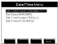
- Enter Date/Time menu
Menus > System > Date/Time
-
Verify 5X00 current date and time.
-
If necessary, use ▲ and ▼ to scroll and highlight submenus.
-
Press to select.
-
Configure submenus.
-
Press Exit Menu to save setting and return to Run Screen or press Back to System menu.
Notes:
- Changes to Date and Time menus take place immediately and are saved prior to Exit Menu.
- Configured date and time formats are carried throughout menus and logs.
- Any active (with energized relay) timer system, including 10-event daily timers, feed timers, and/or dosing timers, are NOT recalculated when the 5X00 time and/or date is changed. Once a timer relay has been energized, it runs for the duration and does not reset based on changes to the 5X00 date and time. Example - timer 1, event 1 is configured to come on at 9:00am for 10 minutes. Timer relay energizes at 9:00am. At 9:05am the 5X00 time is changed to 10:05am (for daylight savings adjustment). The timer relay will de-energize after five additional minutes. The 5X00 time will be 10:10am. The event log will reflect the configured 5X00 time when the event occurred. In this example, 9:00am for the start and 10:10am for the end.
- The time must be manually changed for daylight savings time adjustments. Daylight savings note: Sensor data log records are not overwritten when the
clock is changed unless the instrument is power cycled after changing the data and time. Example - the data log interval is set to 15 minutes. Current instrument time is 6:00 am. The clock is adjusted to 5:00 am for daylight savings time. The 5X00 sensor log contains four 15 minute interval records from 5:00 am to 6:00 am from prior to time change. Sensor data logs are not overwritten with new values for the repeat of 5:00 am to 6:00 am 15 minute intervals unless the instrument is power cycled.
- Menu configurations are saved to the system by pressing Exit Men to return to the Run Screen and not when the change is made in the menu. Exception - Date and time and clear data logs are updated immediately to the system, not when Exit Men is pressed.
Display Settings
Menus → System → Display Settings
Sensor and Aux conditions are displayed at the Run Screen. Use the Display Settings menu to configure how many systems display on one page at the Run Screen. Up to six systems can be displayed on one Run Screen page. Multiple Run Screen pages scroll at user configured speed (1-65535 seconds).

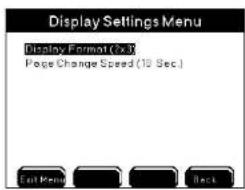
- Enter Display Settings menu
Menus → System → Display Settings → Display Format


- Use ▲ and ▼ to scroll and hig


- Press to select


- to save configuration an


Notes:
- At 1x2 & 2x2 display settings, analog aux values over 7 digits will overlap on to the adjoining sensor window. Adjust aux display format to lower resolution. - Because of font limitations, 1X2 and 2X3 display formats do not show all 20 characters of a 20 character name. Typically only 13 characters are displayed.
ODO Cal K (5500D-01, 5500D-02 and 5500D-04)
Menus → System → ODO Cal K → DO1-DO4
5500 The ODO Cal K system menu appears only in 5500D-01, 5500D-02 and 5500D-04 instruments. This menu is for viewing and uploading DO sensor cap calibration codes. Uploading ODO sensor cap calibration codes is required whenever a sensor cap is replaced.
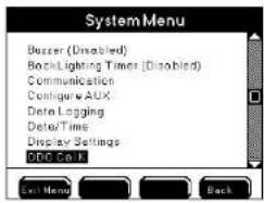
Cap calibration codes are not stored in the 5500D instrument but rather are stored in the ODO sensor. Upon selecting DO-1, DO-2, DO3 or DO-4 at the ODO Cal K menu, communication initiates between the instrument and the sensor. An ODO sensor has six cap calibration codes. They are known as K1, K2, K3, K4, K5 and KC.


Direction to view or upload ODO sensor cap calibration codes:
- Enter ODO Cal K menu
Menus → System → ODO Cal K → DO-1, DO-2, DO-3, DO-4
- Select DO-1, DO-2, DO-3 or DO-4
ODO sensor cap calibration codes are displayed
If the 5500D is unable to obtain the cap calibration codes from the ODO sensor the below error message is displayed. Typically a retry after several seconds will display the ODO sensor cap calibration codes. If the calibration codes cannot be displayed confirm that the ODO sensor is displaying a value at the run screen.

- To upload sensor cap calibration codes select K1, K2, K3, K4, K5 or KC.
- Use alpha/numeric keyboard to enter the values exactly as provided on the sensor cap instruction sheet sent from YSI.

- After entering all K values press

of the entered values. (Do NOT press Exit Menu) softkey. Pressing the

Cal K values will not be changed.)
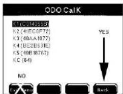
When invalid calibration code data is entered, the below message appears.
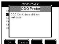
- If no validation error message is displayed, the ODO calibration codes
were entered correctly. Exit Menu to save and return to run screen.
Notes:
- It is not necessary to load sensor cap coefficients when a new ODO probe is installed. A new cable/probe assembly has a sensor cap installed and the sensor cap coefficients are preloaded into the probe at the factory.
- If ODO calibration codes are not uploaded when the sensor cap is replaced the ODO may not operate accurately.
Downloader/Updating 5X00 Firmware
Like all microprocessor based instruments, it may be necessary to upload revisions to 5X00 firmware. Download new firmware using the Flash Programmer utility in AquaManager. A serial RS232 connection is necessary to run the Flash Programmer utility.
The instrument firmware may get corrupted if any of the following occurs during a 5X00 firmware update:
- Firmware Updater window utility is closed;
- AquaManager is closed;
- RS232 cable is removed from 5X00 or PC com port;
- power is disconnected from 5X00.
If the 5X00 firmware becomes corrupt and is not updated properly, it may be necessary to return the instrument to YSI.
Firmware Updater Directions
- Wire RS232 connection. See RS232 Communication - page 66. (Disregard if already using RS232 connection.) Note:
Connect RS232 directly into slaves in order to upload firmware to slaves. Disable slaves at the master to avoid slave failure alarms when uploading - Menus → System → Communications → Network → Master.
- Enable the Force Serial Port on 5X00s wired and configured with an ethernet device - page 101.
- Verify that the baud rate in 5X00 Communications menu is configured to 115200.
- From the AquaManager Explorer window, access the Flash Programmer utility from the pull down menu: Tools→Instrument tools→Update Firmware.

- Configure PC com port number (1-8) in Flash Programmer.
Notes:
- Use only a Tripp-Lite Keyspan USB-Serial Adapter, model USA-19HS YSI p/n 773.
Configuring the 5X00
- When using USB-Serial Adapter, verify that the port number assigned during driver installation is the same port configured when using AquaManager Flash Programmer.

- AquaManager Program Folder includes the latest version of instrument firmware. The latest firmware is stored as an .mdb file in the PC Program Files>AquaManager>Firmware. At AquaManager, Firmware Updater>File>Load Firmware Database. Locate and load this file into the Firmware Updater.

- Select "Yes" and the following screens will appear.
On
instrument

On
PC
YSI 5200A/5400/5500 Bootstrap Loader screen Flash Programmer uploading firmware into 5X00
Configuring the 5X00
Note:
- If the YSI 5200A/5400 Bootstrap Loader screen does not appear at the instrument after above steps manually place 5X00 in downloader at Menus → System → Downloader. Close and reopen AquaManager. Reopen Flash Programmer and repeat steps starting at 6.
- Power cycle to exit downloader and return to run screen. Do not power cycle during an active upload.

- If after manually placing the 5X00 into downloader and the Flash Programmer utility still does not upload firmware see Force Downloader - page 130.
- The 5X00 will reboot (power cycle) when firmware upload is complete.

-
Select "ok" when this window appears
-
Close Flash Programmer.
- Verify version information to confirm downloaded code:
Menus → System → Version
- If applicable, disable Force Serial Port configuration.
Notes:
- During upload, 5X00 systems are placed into Service Hold which de-energizes any active systems including energized relays. See SVR Hold Menu - page147 for additional information. No "off" event is created for system relays that de-energize when 5X00 is placed in downloader. Systems are reset when power is cycled after downloader.
- All logs and unit configuration are retained when 5X00 firmware is updated.
- Display board code loads first, followed by control board code. The display board screen flickers when display board code is loading. The display stops flickering when the control board code is loading. The Firmware Updater progress bar will complete two full scrolls during firmware updating.
- Total download time is approximately nine minutes; eight minutes to upload display board firmware and about one minute to upload control board firmware.
- Autopoll must be shut down when firmware is uploaded to 5X00.
Flash Programmer Updater Messages
The Firmware Updater program may respond with one of the following messages to indicate that the upload did not occur.
"Timed out" or "Could not find Unit" messages indicate a communication problem between PC and 5X00. Reconfirm Communication menu configuration, com port settings, and RS232 connections. (A power cycle may be required to access the Communications menu.)


"Unit is Up-To-Date" indicates that the 5X00 has most recent firmware and upload is not necessary.
Force Downloader
If above steps result in errors and if the upload is still unsuccessful, it is possible that the 5X00 is not in downloader mode. Force the 5X00 into downloader following the steps below.
A status LED on the I/O Board must be visible to determine if the 5X00 is in downloader mode. The status LED flashes about 10 times in 5 seconds when in downloader mode. When not in downloader mode, the status LED flashes more quickly about 15 flashes in 5 seconds. The led at the "status/reset" location of the I/O Board indicates the current status of 5X00 boards.
Directions to Force 5X00 into Downloader
- WARNING: Disconnect external power to 5X00. (AVERTISSEMENT : déconnectez l'alimentation externe de l'unité.)
-
Open front panel - page 41.
-
Depress reset button on I/O board (see figure below) and hold down the enter key on the front panel. Use a paper clip or other sturdy piece of wire to access the reset button through the I/O metal plate. Ensure that you are only touching the reset button on the I/O board and the enter key, then turn power on. The Downloader (bootstrap loader) screen should appear on the instrument.

- Proceed with uploading firmware with Flash Programmer Updater utility. Repeat steps starting at 8 of Firmware Updater directions.
General Alarm
Menus → System → General Alarm
The General Alarm triggers the buzzer, general alarm relay, general alarm icon, and 5X00 emails. Sensor and aux system alarms, slave failure (networks), low battery alarms and ODO probe failure (ODO probe failure alarms apply to only 5500D-01, 5500D-02 and 5500D-04 instruments) alarms trigger the General Alarm when enabled. If individual system alarms are not enabled, the General Alarm will not trigger.
The General Alarm (buzzer, relay, emails, icon) remains active until one of the four softkeys Menuz Control Mag's Sive Hold on the front panel is pressed. Pressing one of the four softkeys while in the Run Screen stops the buzzer, de-energizes the General Alarm relay, stops 5X00 emails, and removes the General Alarm icon. Pressing one of these keys also resets the sensor and aux alarm systems. If the alarm condition still exists after Alarm Hold period(s), the General Alarm triggers again. Low battery and slave failure alarms are not reset when softkeys are pressed.
Sensor alarm values set the acceptable control range. When a sensor reports a value ≤ low alarm value or ≥ high alarm value, the alarm system becomes active after the alarm hold off period. See Sensor Setup section, Controls and Alarms - 152 for additional information. If an alarm system is active and alarm relay is enabled, the alarm relay energizes.
Notes:
- The Run Screen must be displayed during normal operation. All alarm functions (5X00 email alarms, energizing of enabled alarm relays, alarm icons, and buzzer) are suspended in 5X00 menus. Alarm systems are reset when menus are exited to Run Screen.
- The General Alarm system is disabled during system-wide events such as service hold and downloader.
- Sensor and Aux alarms must be enabled to trigger the General Alarm.
Alarm Hold Off
Menus → System → General Alarm → Alarm Hold Off → Time Units
General Alarm Hold Off is the length of time the alarm condition must exist before the General Alarm system becomes active.
Notes:
- To avoid alarms for spurious events set the Alarm Hold Off > than 0.
- Aux system alarms are triggered after the Aux hold off time, and not after the General Alarm hold off time.
- Low battery alarm has a five (5) second hold off that is not user selectable.
Relay
Menus → System → General Alarm → Relay
NEW The General Alarm relay can be wired and configured to any networked output relay. The configured relay energizes when the General Alarm system is active. See page 86 for explanation of local versus remote instruments.
Configure General Alarm relay
Use AquaManager to configure system inputs and outputs - page "Use AquaManager to configure Sensor Setup menus" on page 150.
- Wire relay output device to local instrument, or any networked 5X00 instrument - page 54.
OR
- Wire relay output device to REM - see IOEM/REM Safety and Installation guide>Chapter 3>Step 4>Wire REM Relay Outputs.
2. Enter General Alarm Menu
Menus → System → General Alarm > General Alarm Menu opens

3. Use

to scroll and highlight submenus.
-
Press to select.
-
Enable and configure Alarm Hold Off and Alarm Hold Off time and time units. Use AquaManager to configure system inputs and outputs - page 148. OR
-
Enter General Alarm Relay Menu>General Alarm Relay menu opens A. Select Instrument to enter device address menu and configure instrument whose relay will be used for this instrument's general alarm output.
Notes:
- Device Address menu displays a generic list of instruments being Local Machine, Master and Slaves 1-31.
- Device Address menu always display slaves 1-31 regardless of the actual number of slaves wired to the node network
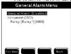
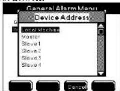
B. Select Relay to enter Relay menu and configure instrument relay channel that will be used for this instrument's general alarm output.
Note:
When Device Address is anything other than Local Machine all relay assignment menus remain generic. This means that regardless of the type of remote instrument being configured Relays 1-8 are displayed. This is true for slave 5200A and REM remote devices which only have 4 relays.

-
Press to Eup Menu configuration and return to Run Screen.
-
Test General Alarm Relay output at >System>Service>Output Test - page 144 or create a general alarm event to verify configured general alarm relay energizes.
Note:
The General Alarm does not create an event log or control message regardless if a General Alarm relay is enabled.
Name Devices/Sensors
Menus → System → Name Devices/Sensors
Names can be user configured for 5X00 instrument, sensor aux and E-Aux systems, and relays. Default names are displayed at the local instrument when names are not user configured. 5X00 default system names are: DO1-4 (depending on 5X00 model number), Aux 1-6, E-Aux 1-8 and Relay 1-8. Default names for Aux 3-6 configured as temperature systems are Temp 1-4. Instrument and Relay names are displayed at many local instrument's menus. System names are displayed at Run Screen, sensor setup configuration, and control messages menus and screens. Because networked instruments can use relays from remote networked instruments, it is important to know that configured instrument and relay names are displayed differently at local versus remote instruments' relay menus. See additional information starting on page 136.
Configure device and sensor names
- Enter Name Devices/Sensors menu
Menus → System → Name Devices/Sensors>Name Devices/Sensors Menu opens
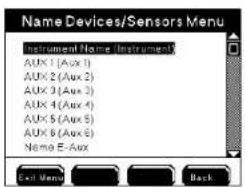

-
Use ▲ ▼ to scroll and highlight submenus.
-
Press to select.
-
Use keypad to configure name.
-
Press Exit Menu to save configuration and return to Run Screen.
Notes:
See information regarding instrument and relay name conventions across a node network - page 136.
- Names can contain up to 20 characters.

- Use AquaManager to easily configure names using the PC keyboard. See AquaManager help.

- Names uploaded in the temperature system name field within the temperature system tab are displayed at the run screen, configuration menus, and control messages menus.
- Instrument, Aux & Sensor Names are not cleared at Reset to factory menus.
- Relays names are cleared at "reset relays", "reset all systems" and "reset to factory/reset all" service menus.
- 5X00 default system name is displayed at event, sensor, and calibration logs, regardless if system name is user configured.
- At alpha/numeric keypad enter character then press "Clear" at keypad and then press 📄 to clear user configured names.
- Aux and E-Aux system names can also be configured at: Menus → System → Configure Aux /Configure E-Aux→Aux 1-6/Eaux 1-8→Name
- Because of font limitations, 1X2 and 2X3 display formats do not show all 20 characters of a 20 character name. Typically only 13 characters are displayed.
- The instrument name is not shown at Run Screen. The instrument name is shown at relay enable menus for a local instrument only.
- Certain menus (i.e. configure aux) display up to 18 characters of the device name. “...” is shown at the menu if the name exceeds 18 characters.
Below are screen shots of Run Screen and system low alarm menu displaying user configured system name CATFISH NE.


Instrument and relay name conventions across a network.
See page "Local vs Remote Instruments" on page 86 for definition of local versus remote instruments. Configured instrument and relay names are displayed differently when local versus remote instruments are selected at relay menus. An instrument is selected at the sensor>control/alarm system>Instrument window. The instrument window displays a generic list of instruments being Local Machine, Master, Slaves 1-31. Only the Local Machine user configured name is displayed. A relay is selected at the sensor or system>relay menu. The relay window displays a generic list of relays 1-8 regardless if a remote 5200A or REM instrument is selected which instruments have only 4 relays.
Generic Instrument window Generic Relay window
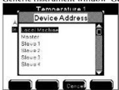

Notes:

- User configured instrument, system and relay names are displayed throughout AquaManager systems management tab. User configured names are also displayed at mapping.
- Local instrument and relay names - Sensor instrument menu displays configured (or default) local instrument name at instrument field when a prior relay assignment has not been made.

- Sensor relay menu displays configured local relay name at relay field once a local relay has been configured at the menu being viewed.
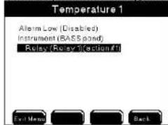
- Remote instrument and relay names - When Device Address is anything other than Local Machine all relay assignment menus remain generic. This means, Master and Slave instruments do not display their configured names, but rather the generic names of "Master" and "Slave 1-31."
Password
Menus → System → Password
Enable and set the password in the password menu. Once the password is enabled and saved, 5X00 system menus are not accessible without first entering the correct password at the Run Screen. The password can contain up to 12 characters.

request for password to enter menus password menu
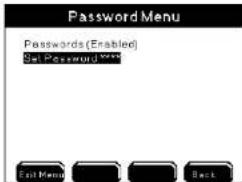
Configuring the 5X00
- Enter Password menu
Menus → System → Password
-
Use ▲ and ▼ to scroll and highlight submenus.
-
Press to select.
-
Enable and configure submenus.
-
Press Exit Menu to save configuration and return to Run Screen.
Notes:

is not password protected.

displays at Run Screen when password is enabled.
Power Fail Menu
Menus → System → Power Fail
In the event of AC power failure, an AC version instrument's power switches to DC if properly wired. The switch from AC to DC power is automatic and does not require 5X00 configuration. Enable Power Fail AC Monitor to generate an event when AC power fails and is restored. Because AC powered 5X00s may not reboot properly after an AC power failure or AC power surge, it is highly recommended to use a battery back system when 5X00 is powered primarily by AC power. See page 216 for DC battery maintenance information.

Disabling the Power Fail System will disable AC power events and disable the General Alarm in the event of low battery for DC power. Disable Power Fail AC Monitor when powering 5X00 by a DC power source.
Enable Low Battery Monitor to trigger General Alarm in the event DC voltage is ≤ to low battery trigger. The Low Battery Alarm Hold Off time is five (5) seconds and cannot be user configured. Once the low battery general alarm has been acknowledged by pressing one of the 4 softkeys, it is not reset. See General Alarm - page 131.
Configuring the 5X00
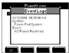
-
Verify AC and DC power supplies are properly wired and powered. See wire power - page 45.
-
Enter Power Fail Alarm menu and submenus Menus → System → Power Fail
-
Use ▲ ▼ to scroll and highlight submenus.
-
Press to select.
-
Enable and configure submenus
-
Press Exit Menu to save configuration and return to Run Screen.
Notes:
- Press Mag's to view AC power fail events.
- icon at Run Screen indicates that the 5X00 DC power is ≥ Low Battery Trigger value with Low Battery Monitor enabled.
- icon at Run Screen indicates DC voltage ≤ the Low Battery Trigger when Low Battery Monitor is enabled.
- Low battery alarm is not reset when front panel softkey is pressed.
- AC power fail does not generate a general alarm.
Serial Number
Menus → System → Serial Number
The serial number is displayed at the serial number menu. The serial number is required when contacting YSI customer service. The serial number is also necessary to configure AquaManager. 5400 instruments' serial numbers begin with "54-" followed by seven digits. 5500D-01, 5500D-02 and 5500D-04 instruments' serial numbers begin with "55-" followed by seven digits. Serial numbers are generated at the factory and cannot be changed by the user.

Service
Menus → System → Service
The Service menu includes submenus to configure and Reset Clean Probe timer, Reset Systems to factory defaults, and test outputs including relays and IOEM 4/20mA outputs.

Reset Clean Probes
Menus → System → Service → Reset Clean Probes
Enable clean probe timer, configure the duration, and reset clean probe days remaining from Reset Clean Probe menu. Selecting reset at this menu resets clean probe
timer to the user configured value. clean probe timer expires.

icon displays at Run Screen when the

Reset Clean Probe timer at the Mac's or at the Reset Clean Probes menu.
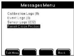
When prompted "Are you sure?", select "Yes" to reset the clean probe timer to the user configured number of days.
Reset To Factory
Menus → System → Service → Reset To Factory
The Reset to Factory menu allows resetting of some or all of 5X00 systems to factory defaults. Example - if Clean Probe Timer is user configured to 60 days, performing a factory reset will reset the Clean Probe Timer to 90 days which is the factory default setting and not the user configured value. See Appendix B Menu Maps starting on page 225 for factory default settings for all systems.
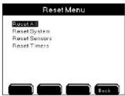
Notes:
- "Reset All" and "Reset All Systems" resets time format to 12 hour and date format to MMDDYYYY.
- It is strongly recommended that user configuration be maintained in a log by the user.
- Instrument, aux, sensor, and suffix names are not reset at any reset to factory menus. Relay names are reset at "reset relays" and "reset all" menus.
- Control icons and control menu messages are displayed for 30 seconds after pressing Full Menu from reset to factory menus for any system that was active (energized relay) prior to factory reset.
Reset All
Menus → System → Service → Reset To Factory → Reset All
Resets all systems, sensors, and timers to factory defaults.
- Use ▲ and ▼ to scroll and highlight submenus.
- Press ← to select.
- When prompted, "Are you sure?", select one of the following to confirm,

- Press to Exit Maru configuration and return to Run Screen.
Notes:
- Display contrast, backlight timer, and buzzer can only be reset to factory defaults through this menu.
- Sensors must be recalibrated after performing a factory Reset All and/or Reset Sensor.
Reset System
Menus → System → Service → Reset To Factory → Reset System
Specific systems or all systems in the Reset System menu can be reset to factory defaults.

- Use ▲ and ▼ to scroll and highlight submenus.
- Press to select.
- When prompted, "Are you sure?", select one of the following to confirm,

- Press to Exit Menu configuration and return to Run Screen.
Reset Sensors
Menus → System → Service → Reset To Factory → Reset Sensors
Specific sensors, aux system, or all sensor and aux systems listed in the Reset Sensors menu can be reset to factory default.
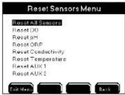
- Use ▲ and ▼ to scroll and highlight submenus.
- Press to select.
- When prompted, "Are you sure?", select one of the following to confirm,

- Press to configuration and return to Run Screen.
Note:
- Perform a sensor calibration after resetting a sensor to factory default.
Reset Timers
Menus → System → Service → Reset To Factory → Reset Timers
A specific timer, feed timer, or all timers listed in the Reset Timers menu can be reset to factory defaults.

-
Use ▲ and ▼ to scroll and highlight submenus.
-
Press to select.
-
When prompted, "Are you sure?", select one of the following to confirm,

- Press to configuration and return to Run Screen.
Output Test
Menus → System → Service→Output Test
Use the Output Test menu to verify that local relays and remote device relays and IOEM 4/20mA output channels, are wired and communicating correctly over the network. Entering this menu turns off any active relays and disables any sensor, aux, and timer system relays from energizing regardless of value or condition. Systems are not reset when the Output Test menu is exited. To reset systems after exiting the Relay Test menu power cycle the 5X00 whose output channel was tested. See note below.
Note:
- Timer and control icon(s) remain at the Run Screen until the system is reset. Example - the timer icon remains at systemwide location until the end of the timer cycle that was stopped when the output test menu was entered even though the relay is not energized. To reset systems after exiting the Relay Test menu, power cycle the 5X00.
Directions to test outputs
- Enter Output Test menu
Menus → System → Service → Output Test > Output Test information warning window is displayed
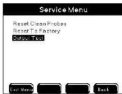

- a Screen to proceed with Output Test. Output Test Menu opens:
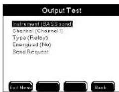
3
at Instrument menu. Device Address menu opens. Scroll and select networked instrument whose relay or channel is to be tested.
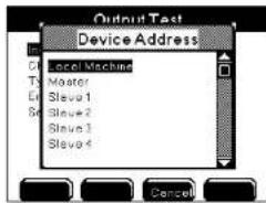
Note:
- If local machine is selected, configured instrument name, if configured, is displayed after selection. See notes regarding local versus remote instrument and relay names in 5X00 menus - page 136.
4
at Channel. Channel menu opens. Scroll and select channel/relay to be tested.
Notes:
- Channel names are always listed as generic channels 1-8 regardless if local machine is selected and the selected relay name has been user configured. Channel 1-8 are always listed regardless if instrument selected is a 5200A or an REM which instruments have 4 relay channels, and not 8 relay channels
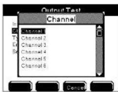
- Scroll and select Relay or 4/20mA output type.

- 4/20mA outputs test an IOEM 4/20mA output channel. For 4/20mA output test, configure a Milliamp value. The Milliamp range is 0.00 to 21.00.

- Select Yes at Energized menu to toggle state of output.

- Scroll and select Send Request. at 5X00 Run Screen to send a command to the local, or networked, instrument to trigger configured output test condition.
- Verify locally, at the instrument whose output is being tested, that output is at correct state or value.
- Exit Menu after completing instrument channel output testing.
Service Hold
Menus → System → Service Hold
Pressing Sync Hold at the Run Screen puts the 5X00 into Service Hold. The Service Hold time is user selectable (1-255 sec, min, or hours). Service Hold turns off any active relays and disables any sensor, aux, and timer system relays from energizing regardless of value or condition. 5X00 alarm emails are not sent during service hold. After the service hold time expires, or is cancelled, the sensor systems are reset after 30 seconds. Timer systems are not reset.

- Use ▲ and ▼ to scroll and highlight submenus.
- Press to select.
- Enable and configure submenus.
- Press Exit Menu to save configuration and return to Run Screen.
- Press Svc Hold at Run Screen to enter Service Hold. See Svr Hold - page 196 for additional information.
Note:
- Place the 5X00 in service hold as instructed in step 3 of calibration checks in Maintenance - page 209.
Configuring the 5X00
Configuring the 5X00
Version
Menus → System → Version
The Version menu contains information about the 5X00 including: display and control board firmware code version, firmware compile date and time, control board temperature, AC and DC voltage and model number.
Notes:
- Firmware version information is required when contacting YSI support.
- The clock chip temperature range starts at 0°C. Values < 0°C are not valid numbers.
- The normal operating range temperature will be a few degrees above ambient.
- AC powered units will run at a higher temperature than DC powered units.
- To view current AC and DC power values to return to run screen and then return to menu. Power information does not refresh when version menu is open.
AquaManager and the System Menu
AquaManager users can configure most 5X00 system menus from a PC. After polling the 5X00, use "Systems Management" from the node window to view and upload 5X00 configuration. System menus are configured at the Setup tab selections.
Notes:
- Always manually poll the 5X00 after uploading configuration changes and verify uploaded information is retained. When configuration changes are uploaded using AquaManager at the same time configuration changes are being made by a user in the menus on a 5X00 instrument, the AquaManager uploads may not be saved depending on the timing of keystrokes at the 5X00. The Run Screen must be displayed during normal operation. If the 5X00
is not at the run screen during AquaManager uploading, pressing at the 5X00 will only save certain configuration changes.
See Chapter 5 AquaManager - page 197 and AquaManager online help for additional information.
Configuring the 5X00
Configuring the 5X00
Sensor Setup
Menus → Sensor Setup → Aux 1-6
→ E-Aux 1-8
→DO1-4
Use AquaManager to configure System inputs and outputs
NEW Any networked 5X00 and REM instrument relay can be configured to any networked 5X00 sensor control or alarm system. In addition, any E-Aux system (see page 108) can be configured to use any networked IOEM input channel as its input source. See local versus remote instruments on a network - page 86. Because of differences in how system relay outputs and E-Aux system inputs are configured locally at a 5X00 instrument versus using AquaManager, it is strongly recommended that AquaManager be used to configure all 5X00 sensor setup menus. AquaManager contains a number of software checks that help to validate E-Aux input and 5X00 system output relay assignment configuration. These same checks do not exist when configuring systems directly at a 5X00 instrument. AquaManager maintains an up to date table of all node network instruments. This table gives AquaManager the ability to display only networked instruments at E-Aux source input and system relay output pulldown menus. (This AquaManager table is not visible to the user.)
An Example of configuring a 5X00 system control relay at an instrument versus using AquaManager is provided below. The node network used in the example includes a master (being a 5500D-04) and 4 slaves (slave 2 being a 5500D-02; slave 4 being a 5400; slave 11 being a 5200A; slave 16 being an REM).
Instrument configuration - the control relay instrument menus displays a generic list of instruments. See instrument and relay name conventions - page 136. Any instrument from the generic list can be selected/configured. This generic list in no way accurately depicts the instruments on the actual node network. In this example, the node network consists of a master and slave 2, slave 4 and slave 11 and slave 16, yet at the system control instrument menu a generic list of instruments is displayed. Which generic list includes Local Machine, Master and Slaves 1-31 and not just the 4 instruments on the node network. The relay list also displays a generic list which displays relays 1-8 for all instruments. This generic list does not take into account that 5200As and REMs have 4 relays and not 8 relays. Instruments. See screen shots below of instrument and relay menus at instrument.
Control system instrument menu

Control system relay menu

AquaManager configuration - in the alternative, AquaManager knows what instruments are actually on the node network and consequently knows actual relays available on each instrument. In this example, only the Master 5500D-04 and slaves on the network are available at the instrument menu pull down. Each instrument also will display only available relays based on the instrument type. In the relay menu screen shot below 4 relays are displayed because Slave 16, an REM, was selected. See screen shots below for AquaManager pull downs.
Control system instrument menu

Control system relay menu
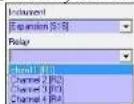
Sensor Setup
Aux, E-Aux and DO set points (setpoint, control and alarm), control mode (set point, PID/PWM, or PID 4/20mA) and sensor system relays are configured in Sensor Setup menus. All networked instrument relays can be configured for control and alarm output devices - see Use AquaManager to configure System inputs and outputs - page 150. Properly wired and configured relays energize when a control or alarm system is active. Alarm notifications can be sent via email or cell phone (SMS messaging) - page 90.
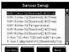
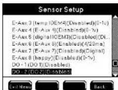
Notes:
- For normal operation, the 5X00 must be at the Run Screen. Alarm functionality (email alarms, activation of assigned alarm relays, alarm icons, and buzzer) is suspended when 5X00 is not at Run Screen.
- Sensor system must be enabled in order to display values at Run Screen. Control and/or alarm relays will not energize regardless of value if the sensor system is disabled.
- There is a 30 second delay at power up before control, timer, and alarm systems become active.
- There is a 30 second sensor system hold off when sensor configuration is changed. See 30 Second Sensor System Hold Off - page 163.
- Calibrate sensor prior to use. See Calibration - page 82.
- "Over" and "Under" readings are displayed when DO sensor is measuring outside it's operating range - see DO range specification - page 14 DO control and alarm functions including relays are suspended when a sensor is reading "Over" or "Under."
- "Over" and "Under" are not displayed for aux temperature systems when temperature values are outside the temperature operating range - see Temperature Range Specification - page 15. Temperature system controls and alarms will not operate correctly when values are outside the temperature operating range.
- DO "Over" and "Under" readings most likely indicate that the sensor needs to be serviced or replaced, or a bad probe or cable connection exists.
- One relay can be assigned to multiple systems. It is essential that the relay configuration be verified in order to avoid conflict of operation of wired relay devices. Assigning one relay to multiple systems can result in invalid operation.
Control Mode
Menus → Sensor Setup → Aux 1-6 → Control Mode
→ E-Aux 1-8→Control Mode
→DO 1-4 →Control Mode
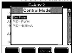
Configure DO, Aux and E-Aux non digital systems to control and alarm at user configured values to best manage your aquatic system. Sensors and aux and E-Aux analog devices report values to the 5X00. Wire and configure peripheral devices
(outputs) to turn on and off in order to maintain certain water conditions as close to the setpoint as possible. 5X00 instruments have three control modes. They are Set Point control which is described starting on this page, PID/PWM and PID 4/20mA control which are described starting on page 159. Control mode configuration determines how a 5X00 instrument maintains a water parameter as close to setpoint as possible. System menu options change based on the control mode.
Follow page links below to see examples of instrument menus displayed for different control mode:
- E-Aux 4/20mA system Set point control example - page 167;
-Aux and E-Aux digital - page 164. (Digital inputs do not have a control mode selection).;
-Temperature Set point control mode example - page 168;
-DO Set point control mode example - page 173;
-PID/PWM and PID 4/20mA control mode example - page 176;
Notes:
- Aux and E-Aux digital systems do not use control modes. See page 165 for complete aux and E-Aux digital configuration information.
- Sensor Setup menu selections change based on the configured control mode.
- Changing control modes may result in invalid set point, control and alarm value configurations. Always reconfirm control and alarm menu configuration when control mode is changed.
Set Point Control
When a system is operating in Set point control mode control and alarm relays energize when user configured values are reported to the 5X00 from the input sensor or device. A control relay remains energized until the system set point value is processed by the 5X00.* Configure sensor control relays using AquaManager - see page "Use AquaManager to configure system inputs and outputs" on page 150. See Set Point Alarm Values - page 156 for alarm relay functionality.
*exception - high temperature, and high and low analog aux and E-Aux systems may also be configured for a timed set point mode - see page 157.
Follow page links below to see examples of instrument menus displayed for set point control mode:
- E-Aux 4/20mA system Set point control example - page 167;
-Temperature Set point control mode example - page 168;
-DO Set point control mode example - page 173;
Below are screen shots of an E-Aux temperature system menu configured in Set Point control mode.

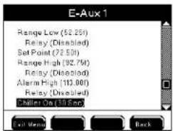
Control relays configured in the Set Point control mode energize when a user configured control value is received from the input device and is processed by the 5X00. Control relays can be configured to raise and/or lower DO and non digital aux and F-Aux systems. Configure high and/or low alarm systems to activate peripheral devices and/or to provide alarm notification messages when alarm condition(s) exist. Configure values outside of acceptable operating control range as high and low alarm values.
Set Point Control Values
Range low and Range high values set the acceptable operating range for the water system. Control system(s) do not become active when value(s) are within acceptable control range. See figure 4.8 - page 155. Enabled control relays energize when the sensor reports a value ≤ the range low control value or ≥ range high control value. Control relays are typically wired to devices used to raise or lower certain water parameters in order to maintain the system as close to set point as possible. Control relays remain energized until the sensor reports a value ≤ set point (when dosing down to lower specific water parameter) and/or ≥ set point (when dosing up to raise specific water parameter). Exception - timed control is available for high temperature and high and low analog aux and E-Aux systems - see page 157. In timed set point control mode control relays are controlled by timers as opposed to water system value. Sensor low control range starts at -1 significant digit below set point value. High control range starts at +1 significant digit above set point value.
Figure 4.8 shows how the 5X00 operates based on a set point control sensor setup configuration. In the example provided DO range low and range low 2 devices will energize at ≤ 5.0 and ≤ 4.0 respectively. The alarm low system becomes active at ≤ 3.5.
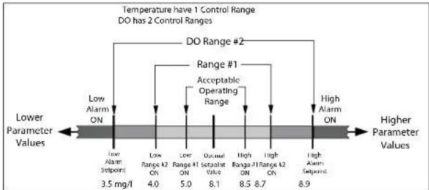
flowchart
graph TD
    A["Lower Parameter Values"] --> B["Low Alarm ON"]
    B --> C["DO Range #2"]
    C --> D["Range #1 Acceptable Operating Range"]
    D --> E["High Alarm ON"]
    E --> F["Higher Parameter Values"]
    G["Lower Parameter Values"] --> H["Low Alarm Setpoint 3.5 mg/l"]
    H --> I["Low Range k2 On 4.0"]
    I --> J["Low Range k1 ON 5.0"]
    J --> K["Occunal Setpoint Value 8.1"]
    K --> L["High Range k1 On 8.5"]
    L --> M["High Range k2 On 8.7"]
    M --> N["High Alarm Setpoint 8.9"]
    style A fill:#f9f,stroke:#333
    style E fill:#f9f,stroke:#333
    style F fill:#f9f,stroke:#333
Figure 4.8
Notes:
- Configure sensor control relays using AquaManager - see page 150.
- Changing control mode may result in invalid set point, control and alarm value configurations. Always reconfirm sensor setup system menu configuration when control mode is changed.
- DO systems have two control ranges. They are referred to as Range Low & Range Low 2 and Range High & Range High 2.
- Control systems remain active when the user is in 5X00 menus.
- Control icons display at the Run Screen when relays are energized - see Icons - page 76.
- Press Control at Run Screen to display active sensor and aux system relays.
- Press Mag's at Run Screen to display events created by control and alarm relays - see Event Log - page 120.
- Control relays are not energized if the 5X00 DO sensor value reads "Over" or "Under."
"Over" and "Under" are not displayed for aux temperature systems when temperature values are outside the temperature operating range - see temperature range specification - page 15. Temperature system controls will not operate correctly when values are outside the temperature operating range. - See Wire Relays - page 54 for information on wiring control output devices on a 5X00 instrument. See IOEM/REM Safety and Installation guide>Chapter 3>Step 4>Wire REM Relay Outputs.
Set Point Alarm Values
Alarm values set the acceptable control range. Alarm system(s) do not become active when values are within acceptable control range. See figure 4.8 - page 155. Enable and configure system alarm(s) to activate alarm output devices(s), view alarm icons, hear audible alarm and/or receive alarm notifications sent via email or cell phone (SMS) - page 90. Configure high and low alarm values to set alarm thresholds. Alarm system(s) becomes active when value is ≤ low alarm value or ≥ high alarm value. Enabled alarm relays energize if alarm condition exists for the general alarm hold off time. Alarm relays are energized until one of the four soft-
keys Nenus Control Msg's Sve Hold is pressed regardless of sensor value. Pressing one of four softkeys resets the alarm system. Alarm systems become active again if, after the alarm hold off period, the alarm condition still exists. Alarm hold off is configured in the General Alarm menu.
When the General Alarm is enabled, (with or without enabled relay), the general alarm system becomes active when any system alarm is active. See General Alarm - page 131.
System low alarm range starts at -1 significant digit below low control value. High alarm range starts at +1 significant digit above high control value.
Notes:
- Configure sensor alarm relays using AquaManager - see page 150.
- It is important to keep the 5X00 at the Run Screen during normal operation. Alarm functionality (email alarms, activation of enabled alarm relays, alarm icons, and buzzer) is suspended when 5X00 is not at Run Screen.
- Alarm icon(s) display at the Run Screen when alarm condition(s) exists for longer than the general alarm hold off time. See Icons - page 76.
- Press Control at Run Screen to display active sensor and aux system relays.
- Msg's to display events created by control and alarm relays - see Event Log - page 120.
- Alarm relays are not energized if the 5X00 DO sensor value reads "Over" or "Under."
- "Over" and "Under" are not displayed for aux temperature systems when temperature values are outside the temperature range specification - see temperature range specification - page 15. Temperature system alarms will not operate correctly when values are outside the temperature range specification.
- See Wire Relays - page 54 for information on wiring control output devices on a 5X00 instrument. See IOEM/REM Safety and Installation guide>Chapter 3>Step 4>Wire REM Relay Outputs.
Timed versus Normal (non timed) Control
Timed control is available for high temperature and high and low analog aux and E-Aux systems. In timed set point control mode control relays are controlled by timers as opposed to water system value. All systems can be controlled in a non timed (normal) control mode by configuring dose on/chiller on time to 0. This will cause the system's control relays to remain energized until the set point value is reached.
In a set point timed mode, a control relay energizes for the dose on time regardless if the sensor reports that a value has returned to the set point value. The control relay deenergizes at the end of the dose time and then waits a user configured "wait", "dwell", or "hold off" time before resampling. If, after the wait time, the system is still in control range the control relay will energize again for the dose on time.
In the case of a temperature high set point time control mode it is recommended to configure the chiller hold off time to a value of eight (8) minutes, or more. This amount of time will help to avoid chiller compressor damage due to many on/offs.
Notes:
- A chiller off time must be configured in the timed mode or the control relay will never de-energize.
- Since most heaters and chillers have their own thermostats, their thermostats can be used as a backup temperature control system. Set the heater thermostat control several degrees above the desired temperature and the chiller thermostat control several degrees below the desired temperature.
- Active sensor control timers are reset after systemwide events. Systemwide events de-energize relays. Example - chiller on time is configured for an eight (8) minute on time. Energized chiller (control down) relay de-energizes when 5X00 goes into Svr Hold. The chiller on relay had been energized for three (3) minutes before the Svr Hold occurred. The Svr Hold time is one (1) minute. If the sensor is reporting control low condition after the service hold time period, the chiller on time will be for eight (8) minutes and not the remaining five (5) minutes of the chiller on time prior to entering Svr Hold.
- Control down relay (chiller) energizes for original "on time" if chiller "on time" is reconfigured when relay is energized.
Validation Error and Autofix - Set Point Control Only
When an invalid value is entered at the numeric keypad a Validation Error window displays. An invalid value is either a value outside the range of the sensor system or a value that breaches other settings within the sensor system. Autofix occurs when a high or low control value is entered that breaches the set point value. Examples are provided below:
Low range control value must be < set point value. High range control value must be > set point value. Low alarm value must be < low control value. High alarm value must be > high control value.
Example - entering "63" for DO set point results in validation error because the valid range for the DO sensor system is 0.00 to 60.0mg / l . User must configure value within valid range. In addition, the value cannot breach respective control and alarm system values.
Example - configuring set point value of 8.00 mg/L with range low value of 8.00 mg/l results in validation error. Valid set point range is displayed at validation error display. Press ☐ to return to numeric keypad to enter valid value.

Autofix occurs when a high or low control value is entered that breaches the set point value. Autofix changes the high or low control value by one least significant digit away from the set point value. The set point value is never adjusted.
Example - Entering 8.00 mg/L as the range low value when the set point value is 8.00 mg/L results in an auto fix of the control value. The invalid control value is displayed at the sensor setup menu. Pressing Evil Menu is not an option after saving a value at numeric keypad. Press Back from the sensor setup menu to continue with the autofix. A validation error window is displayed to show that the autofix has occurred. Press OK to return to sensor setup menu. Verify that the autofixed values are configured for user's specific application and reconfigure as needed. Press Evil Menu to save configuration and return to Run Screen.

PID/PWM and PID 4/20mA Control mode
Configure PID/PDW and PID 4/20mA control mode at Sensor Setup menus. (PID/PWM and PID 4/20mA control modes are also referred to as PID control modes). PID stands for Proportional, Integral and Derivative. PWM stands for pulse-width modulation. PID/PWM and PID 4/20mA control modes operate similarly but use different output to control the control outcome. The difference is that a system configured in PID/PWM control mode uses a relay as the output control device and a PID 4/20mA control mode system, instead, drives a 4/20mA output device, such a valve, to control the system. Both control modes use a complex algothrium in determining the best way to sustain water system value(s) around a set point using a relay PID/PWM (on/off) or a value PID 4/20mA. Both control modes can be used to control an output device to maintain a certain water parameter at its set point. Both PID 4/20mA and PID/PWM control modes are feed back control systems. Three factors determine how these control modes seek to maintain water system value(s) around a set point. The three factors are:
-the error (distance) from present measurement of input to set point (present time); -the duration of the error (accumulation of past errors);
-the speed at which the value is approaching the set point (predicts future errors);
PID/PWM and PID 4/20mA control systems are considered active whenever error exists away from the configured set point. PID/PWM and PI 4/20mA control systems are flexible and can be tuned to keep water systems around their set points even though the environment is exposed to disturbances that drive the input value away from set point. An example of a PID control system that most readers will be familiar with is a cruise control system in a car. Acceleration and deacceleration adjustments are continually being made to maintain the car at a constant speed or set point.
PID/PWM and PID 4/20mA control mode allows configuration of high and low alarm systems which alarm systems activate peripheral devices and/or provide alarm notification messages when alarm condition(s) exist.
Follow page link below to see example to configure PID control mode:
-PID/PWM and PID 4/20mA control mode example - page 176;
Notes:
- Changing control method between PID and Set Point may result in invalid setp point, control and alarm value configurations. Always reconfirm sensor setup system menu configuration when control mode is changed.
- PID control is not available for aux digital systems.
- DO system(s) PID set point can be configured using either mg/L or %Sat.
In contrast to the Set Point Control mode - page 153, when a system is operating in PID/PWM or PID 4/20 mA control mode there are no user configured control values. Instead control relays energize anytime a value is reported that is away from the set point and the output on time is proportional to certain conditions and values being reported to the 5X00.
PID/PDW and PID 4/20mA menu configurations are described in following sections.
-Interval - see page 162
-Gain - see page 162
-Reset Interval - see page 162
-Up or down control - see page 161
An example of a PID control mode system configuration is provided at page 176.
NEW .PID 4/20mA Control Mode
A PID (Propotional, Integral and Derivative) 4/20mA control mode system uses an IOEM 4/20mA output device to control the system. The 4/20mA output control device is wired (at an IOEM instrument) - see IOEM/REM Safety and Installation Guide>chapter 3>directions to wire 4/20mA outs for wiring directions and configured (using AquaManager) - see IOEM/REM Safety and Installation Guide>chapter 4>configure IOEM 4/20mA output for configuration directions.
PID Tuning
Each and every water system responds very differently to peripheral control devices due to many factors. Factors that can influence the ability of a control device to maintain a certain set point include size of system, peripheral equipment such as pumps, lighting, system location and the like. While PID tuning is an important and necessary requirement to properly configure the control system it is outside the scope of this document to describe the tuning process. There is a wealth of information available on the www as well as in print. Please familiarize yourself with additional information in order to further your understanding of the PID/PWM control method.
AquaManager includes a PID Tuning tool which allows simulation of various control action values and functions. The PID tuning tool should be helpful in mimicking your system through simulation. The AquaManager PID Tuning tool is explained in detail in the AquaManager Help System. At AquaManager Help Contents>Working with Nodes>PID Tuner.
Set Point
Configure the set point to be the value at which you'd like the system to ideally operate at. Configure the set point at PID mode menu. DO set point can be configured in either mg/L or %Sat at the. Configure at PID mode menu.
Control Up/Down
Configure the PID control system to either control up (Falling, to create a control action to reduce down the system water parameter value) or control down (Rising, to create a control action to increase up the system water parameter value). A PID control can be used only to control the system by either driving the system value up or down. A PID control cannot be used to drive the system value both up and down.
PID Control Actions
Interval, Gain, Reset Interval
Configuration of three control actions allows for greater control and stability of a particular environment. The control actions are Gain (page - 162), Reset/Inteval (page - 162) and Interval (page -162). These three control actions are closely interrelated in terms of how the PID/PWM algorithm works. The objective is to tune and configure these control actions in order that the corrective action (output control on time) performed by the 5X00 results in system stability. That is, the system will hold the set point without oscillating wildly (overshooting or undershooting by significant amounts) over and under the set point. A large amount of oscillation could cause irreparable damage to the system by dosing too large an amount, or too small an amount, of a control dosing additive to the system stream.
AquaManager includes a PID Tuning tool which allows simulation of various control action values and functions. The PID tuning tool should be helpful in mimicking your system through simulation. The AquaManager PID Tuning tool is explained in detail in the AquaManager Help System.
PID Interval control action
Range 1.00 to 999 (seconds)
Configure the interval control action to be the length of time a complete PID/PDW control cycle takes. The control cycle includes both the control relay output on time and the control relay output off time. Example: A 10 second control relay on time and a 10 second control relay off time would represent a 20 second interval time. The 10 second control relay on time would be expected to decrease as the value reaches set point. Interval, Reset interval and Gain control configurations are all interrelated in the calculation of the control relay on time as the algorithm calculates the proper corrective action.
PID Reset Interval control action
Range 0.00 to 100 (seconds)
Configure the Reset control action to be the rate at which the PID/PWM cycle resets. In other words at what interval the past errors are erased and the PID/PWM process begins a new cycle using new errors, and not past errors, in the PID/PWM formula in calculating corrective action. Interval, Reset interval and Gain control configurations are all interrelated in the calculation of the control relay on time as the algothrium calculates the proper corrective action.
PID Gain control action
Range 0.01 to 10 %.
Gain is used to control the percentage of change in the output. Output increases with greater gain. A high gain results in a large change in the output for a given change in the error. A gain of "5" results in an additional 5% output relay on time for each 1% increase/decrease of the measurement. Tuning theory and industrial practice indicate that gain should contribute the bulk of the output change. Interval, Reset interval and Gain control configurations are all interrelated in the calculation of the control relay on time as the algorithm calculates the proper corrective action.
Note:
Once a PID/PDW control relay energizes the relay completes the interval cycle based on the latest ratio error and does not automatically decenergize when the set point is reached. The PID/PWM formula resets all values to 0 once set point value is achieved and the formula is discontinued. This only occurs after the interval time expires.
PID Alarm System
Alarm values set the acceptable control range. Enable and configure system(s) alarm to activate alarm output devices(s), view alarm icons, hear audible alarm and/or receive alarm notifications sent via email or cell phone (SMS) - page 90. Configure high and low alarm values to set alarm thresholds. Alarm system(s) becomes active when value is ≤ low alarm value or ≥ high alarm value. Enabled alarm relays energize if alarm condition exists for the general alarm hold off time. Alarm relays are energized until one of the four softkeys Menus Control Msg's Svc Hold is pressed regardless of sensor value. Pressing one of four softkeys resets the alarm system. Alarm systems become active again if, after the alarm hold off period, the alarm condition still exists. Alarm hold off is configured in the General Alarm menu.
When the General Alarm is enabled, (with or without enabled relay), the general alarm system becomes active when any system alarm is active. See General Alarm - page 131.
Notes:
- It is important to keep the 5X00 at the Run Screen during normal operation. Alarm functionality (email alarms, activation of enabled alarm relays, alarm icons, and buzzer) is suspended when 5X00 is not at Run Screen.
- Alarm icon(s) display at the Run Screen when alarm condition(s) exists for longer than the general alarm hold off time. See Icons - page 76.
- Press Control at Run Screen to display active sensor and aux system relays.
Mag's to display events created by control and alarm relays - see Event Log - page120. - Alarm relays are not energized if the 5X00 DO sensor value reads "Over" or "Under."
- "Over" and "Under" are not displayed for aux temperature systems when temperature values are outside the temperature range specification - see temperature range specification - page 15. Temperature system alarms will not operate correctly when values are outside the temperature range specification.
- See Wire Relays - page 54 for information on wiring alarm output devices.
30 Second Aux, E-Aux and Sensor System Hold Off
Exiting aux, E-Aux and sensor menus after making certain configuration changes places the system in a 30 second hold. During the 30 second sensor hold, control and alarm systems are not active. System(s) becomes active, if, after 30 seconds, the values are reported in control or alarm range. This 30 second hold off allows sensors and aux devices time to stabilize before control and/or alarm systems become active.
Example - DO sensor menu is entered and the control high set point value is changed while a control relay is energized. When Exit Menu is pressed to return to the Run Screen, the DO control relay de-energizes regardless of sensor value. The control relay re-energizes if, after the 30 second hold, the value is still in control range.
Reconfiguration of the following does not place the system in 30 second hold off:
- DO systems - display format, probe type, membrane type, ppt, elevation, temp source, and temp display format;
- Temperature system - display format, chiller on time, chiller on time units, chiller hold off time, chiller hold off time units, set points, enable/disable control relays.
Notes:
- Configuration changes place only the system that has been reconfigured on 30 second hold.
- No "off" event log is created when energized system relays de-energize due to 30 second sensor hold off.
- Control icons and control messages continue to display during the 30 second sensor system hold at the Run Screen regardless if relays are energized.
Aux and E-Aux Hold Off (non temperature aux systems)
Aux and E-Aux Hold Off (user configured) is the length of time the control or alarm condition must exist before the Aux relay energizes. Aux temperature, E-Aux temperature and DO sensor systems do not have control hold off. These systems controls operate as described at set point normal control values - page 154. Aux temperature, E-Aux temperature and DO sensor alarm relays operate as described at set point normal alarm values - page 156.
Note:
- To avoid control or alarm for spurious events, configure the Alarm Hold Off > than 0.
Aux and E-Aux Relay Digital
Menus → Sensor Setup → Aux 1-6
→E-Aux 1-8
Configure digital control/alarm (open/closed), relay, alarms, and hold off in the Aux 1 - Aux 6 and E-Aux 1 - E-Aux 8 Sensor Setup Menu. E-Aux digital systems use an IOEM digital input as the system input. Use digital input type for control, or alarm, based on either a switch open or switch closed condition. Only one relay can be configured in a digital system. Enabled relay will energize based on the condition configured in the control/alarm on menu.
When enabled, Aux digital relay energizes when configured control/alarm on condition occurs. Aux relay energizes after configured aux hold off time. When alarms are disabled and as long as control/alarm on condition exists, the relay remains energized including when menus are entered. Relay de-energizes when the non control/alarm condition is processed by the 5X00 so long as alarms are disabled. If alarms are enabled, the relay de-energizes when one of the four front panel softkeys
Menus Control Msg's Svc Hold is pressed. Pressing one of four softkeys resets the alarm system. The Alarm system becomes active again if, after the aux hold off period, the alarm condition still exists.
Digital events (event log) are identified by aux/E-Aux number, input type (digital), relay condition (on/off), and do not identify digital condition (open, or closed). Aux digital events are not identified as control or alarm events regardless if alarms are enabled.

E-Aux systems use an IOEM channel as the digital input source. See IOEM/REM Safety and Installation guide for wiring and input channel configuration.

Configure Aux and E-Aux digital systems
Before configuring Aux and E-Aux analog systems 1) See - "Use AquaManager to configure system inputs and outputs" - page "Use AquaManager to configure System inputs and outputs" on page 150. AND 2) See Control modes [Set point Control Mode and Alarms - page 153 and PID control mode - page 175.]
Please review - Use AquaManager to configure sensor systems - page 150.

- Wire digital input at IOEM for E-Aux system - see IOEM/REM Safety and Installation guide>Chapter 3>Step 5>Wire non temperature IOEM inputs;
AND/OR
-
Wire Aux digital devices - page 56.
-
Wire relay output device to local instrument, or any networked 5X00 instrument - page 54 for local instrument.
AND/OR
-
Wire relay output device to REM - see IOEM/REM Safety and Installation guide>Chapter 3>Step 4>Wire REM Relay Outputs. Wire any output devices to be used for system.
-
Configure system menu. For Aux - page 102. For E-Aux - page 108.
-
Enter Aux 1-6/E-Aux 1-8 in Sensor Setup menu
Menus → System → Sensor Setup → Aux 1-6
→ E-Aux 1-8
-
Use ▲ ▼ to scroll and highlight submenus.
-
Press to select.
-
Enable and configure submenus. See Aux/E-Aux Digital relay for digital relay functionality - page 164. Use AquaManager to configure sensor setup menus - page 150.
-
Optional - Configure digital 4/20mA output - page 178.
-
Press Exit Menu to save configuration and return to Run Screen.
-
Test system output device(s) at→System→Service→Output Test - page 144 or create an event to verify configured relay(s) energize.
Notes:
- It is important to keep the 5X00 at the Run Screen during normal operation. Alarm functionality (email alarms, activation of enabled alarm relays, alarm icons, and buzzer) is suspended when 5X00 is not at Run Screen.
- At sensor log Aux (1:1.00) is reporting open condition. Aux (1: 0.00) is reporting closed condition.
- Do not enable aux digital alarms when the sensor is in the control/alarm condition. Enabling aux digital alarms when sensor is in control/alarm condition can result in aux system not properly processing existing alarm condition.
- One relay can be assigned to multiple 5X00 systems. It is essential that the relay configuration be verified in order to avoid conflict of operation of wired relay devices. If not configured properly, assigning one relay to multiple systems can result in invalid operation of 5X00.
- Event logs are created when an aux relay energizes and de-energizes regardless if alarms are enabled.
- Aux alarms must be enabled to trigger General Alarm.
- General Alarm may still be active even though aux system is no longer in alarm. See aux relay information below and General Alarm - page 131.
- E-Aux system datalogs are not accessible at the 5X00. They must be viewed using AquaManager.
Aux and E-Aux Analog (0-1VDC, 0-5VDC and 4/20mA)
Menus → Sensor Setup→Aux 1-6
E-Aux 1-8
Configure analog control and alarm low and high values, control and alarm relays and hold off time in the Sensor Setup Menu.
E-AUX E-Aux systems use an IOEM channel as the analog input source. See IOEM/REM Safety and Installation guide for wiring and input channel configuration.


Configure analog Aux and E-Aux systems
Before configuring Aux and E-Aux analog systems 1) See - "Use AquaManager to configure system inputs and outputs" - page "Use AquaManager to configure System inputs and outputs" on page 150. AND 2) See Control modes [Set point Control Mode and Alarms - page 153 (Aux and E-Aux Analog set point control mode can operate in normal or timed mode - page 157) and PID control mode - page 159.]

- Wire digital input at IOEM for E-Aux system - see IOEM/REM Safety and Installation guide>Chapter 3>Step 5>Wire non temperature IOEM inputs;
AND/OR
- Wire Aux analog (non temperature) device - page 56.
- Wire relay output device(s) to local instrument, or any networked 5X00 instrument - page 54 for local instrument.
AND/OR
- Wire relay output device(s) to REM - see IOEM/REM Safety and Installation guide>Chapter 3>Step 4>Wire REM Relay Outputs. Wire any output devices to be used for system.
- Configure system menu. For Aux - page 102. For E-Aux - page 108.
- Enter Aux 1-6/E-Aux 1-8 in Sensor Setup menu
Menus → System → Sensor Setup → Aux 1-6
→ E-Aux 1-8
Configuring the 5X00
- Use ▲ ▼ to scroll and highlight submenus.
- Press to select.
- Enable and configure submenus. Configure control and alarm relay(s) using AquaManager - see page 150.
- Press Exit Menu to save configuration and return to Run Screen.
- Test system output devices at→System→Service→Output Test - page 144 or create an event to verify configured relay(s) energize.
Note:
- It is important to keep the 5X00 at the Run Screen during normal operation. Alarm functionality (email alarms, activation of enabled alarm relays, alarm icons, and buzzer) is suspended when 5X00 is not at Run Screen.
- One relay can be assigned to multiple 5X00 systems. It is essential that the relay configuration be verified in order to avoid conflict of operation of wired relay devices. If not configured properly, assigning one relay to multiple systems can result in invalid operation of 5X00.
- E-Aux system datalogs are not accessible at the 5X00. They must be viewed using AquaManager.
Temperature
Menus → Sensor Setup → Aux 3-6
→E-Aux 1-8
Configure temperature system control and alarm low and high values, control and alarm relays and hold off time in the Sensor Setup Menu.
Aux 3, 4, 5 and 6 can be wired and configured for a temperature sensor. Temperature systems are configured differently for 5400 and 5500D instruments. The differences are explained below.
E-AUX E-Aux systems can be configured to use an IOEM channel as a temperature input. See IOEM/REM Safety and Installation guide for wiring and input channel configuration. E-Aux temperature sources cannot be associated with DO systems for temperature compensation.
Configuring the 5X00

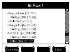
5400 5400 only - Aux configured temperature systems can be configured as the temperature compensation source for any of the four DO channels. Aux configured temperature systems can also be configured as independent temperature systems at any location in the system stream.
5400 Configuration of the DO temperature source is done in the DO Sensor Setup menu - page 173.
5500 The 5500D-01, 5500D-02 and 5500D-04 temperature systems can be configured based on either the aux temperature sensor or the ODO temperature sensor. Aux configured temperature systems can only be configured as independent temperature systems. The DO system temperature compensation value is always taken from the temperature sensor in the ODO probe.
5500 Configuration of the DO temperature source is done in the System → Configure Aux → Temp SourceAux 3-6.
Configure Temperature System Aux 3-6
Before configuring E-Aux temperature systems 1) See - "Use AquaManager to configure system inputs and outputs" - page 150 AND 2) See Control modes [Set point Control Mode and Alarms - page 153 (E-Aux temperature set point control mode can operate in normal or timed mode - page 157) and PID control mode - page 159.]
-
Wire temperature sensor to 5X00 I/O Board (for non ODO sensor temperature system) - page 52.
-
Wire relay output device(s) to local instrument, or any networked 5X00 instrument - page 54.
OR
-
Wire relay output device to REM - see IOEM/REM Safety and Installation guide>Chapter 3>Step 4>Wire REM Relay Outputs.
-
Configure "temperature" input type (for non ODO sensor temperature system) at
Menus > System > Configure Aux > Input Type
- Configure temperature source :
5400
Menus → Sensor Setup → DO 1-4 → Temp Source → User Defined
→Aux
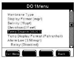

OR
5500
Menus → System → Configure (Aux 3-6 only) → Temp Source → Aux Input → ODO Probe


-
Enter Aux 3-6 in Sensor Setup menu to configure temperature system: Menus → System → Sensor Setup → Aux 3-6 (Temperature 1-6)
-
Configure Control Mode see 152. Menus → System → Sensor Setup → Set Point Control
→PID/PWM Control
- Use

to scroll and highlight submenus.

-
Press to select.
-
Enable and configure submenus. See Control Modes and Alarms for menu functionality - page 152. Use AquaManager to configure sensor setup menus - page 150.
-
Optional - Configure digital 4/20mA output - page 178.
-
Press Exit Menu to save settings and return to Run Screen.
-
Test system output devices at→System→Service→Output Test - page 144 or create an event to verify configured relay(s) energize.
3-6
Configure Temperature System E-Aux 1-8
Before configuring E-Aux temperature systems 1) See - "Use AquaManager to configure system inputs and outputs" - page 150 AND 2) See Control modes [Set point Control Mode and Alarms - page 153 (E-Aux temperature set point control mode can operate in normal or timed mode - page 157) and PID control mode - page 159.]
E-AUX
-
Wire temperature input at IOEM for E-Aux system - see IOEM/REM Safety and Installation guide>Chapter 3>Step 5>Wire IOEM inputs;
-
Wire relay output device to local instrument, or any networked 5X00 instrument - page 54 for local instrument.
OR
-
Wire relay output device to REM - see IOEM/REM Safety and Installation guide>Chapter 3>Step 4>Wire REM Relay Outputs. Wire any output devices to be used for system.
-
Configure Input Type at Menus → System → Configure E-Aux→Input Type and other fields - page 108.
-
Enter E-Aux 1-8 in Sensor Setup menu Menus → System → Sensor Setup → E-Aux 1-8
5.11

to scroll and highlight submenus.
6
- 10am to street.
E-AUX
-
Enable and configure submenus. Configure IOEM Source and Channel. Also see Control Modes and Alarms for menu functionality - page 152. Use AquaManager to configure sensor setup menus - page 150.
-
Optional - Configure digital 4/20mA output - page 178.
-
Press Exit Menu to save configuration and return to Run Screen.
-
Test system output devices at→System→Service→Output Test - page 144 or create an event to verify configured relay(s) energize.
Notes:
- It is important to keep the 5X00 at the Run Screen during normal operation. Alarm functionality (email alarms, activation of enabled alarm relays, alarm icons, and buzzer) is suspended when 5X00 is not at Run Screen.
- The Configure Aux menu will display temperature configured channels as "disabled". This is because aux systems configured as temperature channels no longer function as analog aux channels, but rather function as a temperature sensor system.

- The Sensor Setup menu - page 138 is automatically enabled when an aux 3-6 channel is configured for temperature.


- Aux temperature, E-Aux and ODO temperature values are not accessible at the 5X00. Temperature readings can only be obtained using AquaManager. Readings will be shown in the AquaManager datalog in either °C or °F based on the user configured temperature display format.
- Celsius temperature set point, control, and alarm values are configured to the 10ths place. Fahrenheit values are configured to the 100ths place; however, fahrenheit display values and temperature system operation are based on values truncated to the 10ths digit.
- See 30 Second Sensor Hold Off - page 163.
- Temperature display format (°C or °F) is user selectable. Changing the temperature units automatically adjusts set points to new temperature units.
- Temperature readings are stored in the sensor data log in °C regardless of display format.
- Temperature values affect DO readings. It is important that the temperature sensor is reporting accurately.

- When disabling an aux temperature system that has been assigned to a DO channel, be sure to reconfigure the user defined temp source or enable another aux temperature source for that DO system.
DO 1-4
Menus → Sensor Setup→DO 1-4
Salinity & Temp Compensation for DO Measurements
In order to report accurate DO values, the salinity and temperature of the water around the sensor must be known and compensated for. For accurate DO mg/L readings, the salinity value of the water being monitored should be entered as a ppt (parts per thousand) value in the DO salinity menu.

Each DO system uses the temperature value from the configured temperature sensor or user defined value entered in the DO sensor set up temperature source menu. Aux temperature systems can be assigned to any of the four DO systems.

5the DO system temperature compensation value is always taken from the temperature sensor in the ODO probe.
Notes:
- Changes to salinity affect DO mg/L value.
- Changes to salinity do not affect DO % sat values.

- Configure a temperature source or enter a user defined value for each enabled DO system. Verify that the configured temperature value or assigned temperature sensor is accurate for the water system being monitored around the DO sensor.
Two Range Controls for DO
Each 5X00 DO sensor input has two low and two high control ranges when in Set Point Control mode. This dual range allows for more control over oxygen levels in the water system. Example - DO Set Point Control range low control becomes active causing the air injection system wired/configured to relay #1 to energize. DO levels continue to fall, activating range low control two a pure oxygen injection system wired and configured to relay #2.


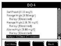
Configure DO Systems
Before configuring E-Aux temperature systems 1) See - "Use AquaManager to configure system inputs and outputs" - page 150 AND 2) See Control modes [Set point Control Mode and Alarms - page 153 (E-Aux temperature set point control mode can operate in normal or timed mode - page 157) and PID control mode - page 159.]
- Install and wire DO probe(s) and membrane and/or sensor cap - 49.
- Wire relay output device to local instrument, or any networked 5X00 instrument - page 54.
OR
-
Wire relay output device(s) to REM - see IOEM/REM Safety and Installation guide>Chapter 3>Step 4>Wire REM Relay Outputs.
-
Configure DO system temperature source: Menus → Sensor Setup → DO 1-4 → Temp Source → User Defined
→Aux 1-6
5400


YSI 5X00 174
OR
5500
Menus → System → Configure (Aux 3-6 only) → Temp Source → Aux Input → ODO Probe
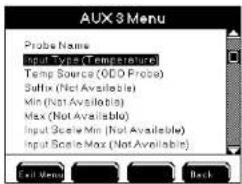

- Configure Control Mode - 152.
Menus → System → Sensor Setup → Set Point Control → PID/PWM Control
- Use

to scroll and highlight submenus.
-
Press to select.
-
Enable and configure submenus. See Control Modes and Alarms for menu functionality - page 152. Use AquaManager to configure sensor setup menus - page 150.
- Optional - Configure digital 4/20mA output - page 178.
- Press Exit Menu to save settings and return to Run Screen.
- Test system output device(s) at→System→Service→Output Test - page 144 or create an event to verify configured relay(s) energize.
Note:
5500
Elevation data can only be viewed and configured locally at the 5500D instrument and cannot be viewed or configured using AquaManager.
PID 4/20mA and PID/PWM control mode menus at instrument
All non digital sensor systems can be configured for PID/PWM or PID 4/20mA control mode.
See PID/PWM and PID 4/20mA Control Mode - page 175 before configuring sensor systems.
YSI 5X00 175
PID 4/20mA menus


PID/PWM menus


Configure PID/PWM or PID 4/20mA control mode
Please review - Use AquaManager to configure sensor systems - page 150 and PID control mode - page 159.]
PID
4/20
-
Wire and configure 4/20mA output channel at IOEM. See IOEM/REM Safety and Installation guide;
-
Enter Sensor Setup menu Menus → System → Sensor Setup → Aux 1-6 → E-Aux 1-8 → DO1-4
-
Use ▲ ▼ to scroll and highlight submenus.
-
Press to select.
- Enable and configure submenus. See PID/PDW control mode for menu field configuration information - page 175;
- Test output at Output Test - page 144;
- Tune output as required;
- Optional - Configure digital 4/20mA output - page 178.
- Press Evil Menu to save configuration and return to Run Screen.
Notes:
- When configuring DO and Temperature systems with PID/PDW or PID control be sure and configure additional menus specific to these systems.
For Do systems additional menus are membrane, display format (mg/l v % sat), salinity and elevation. For temperation systems the additional menu is display format (F/C). Screen shots below display the additional menus for DO and temperature.


- It is important to keep the 5X00 at the Run Screen during normal operation. Alarm functionality (email alarms, activation of enabled alarm relays, alarm icons, and buzzer) is suspended when 5X00 is not at Run Screen.
- At sensor log Aux (1:1.00) is reporting open condition. Aux (1: 0.00) is reporting closed condition.
- Do not enable aux digital alarms when the sensor is in the control/alarm condition. Enabling aux digital alarms when sensor is in control/alarm condition can result in aux system not properly processing existing alarm condition.
- One relay can be assigned to multiple 5X00 systems. It is essential that the relay configuration be verified in order to avoid conflict of operation of wired relay devices. If not configured properly, assigning one relay to multiple systems can result in invalid operation of 5X00.
- Event logs are created when an aux relay energizes and de-energizes regardless if alarms are enabled.
- Aux alarms must be enabled to trigger General Alarm.
- General Alarm may still be active even though aux system is no longer in alarm. See aux relay information below and General Alarm - page 131.
- E-Aux system datalogs are not accessible at the 5X00. They must be viewed using AquaManager.
E-Aux system Offline
At the Run Screen "Offline" at an E-Aux system means the configured IOEM I/O input is a value that the associated 5X00 instrument E-Aux system does not recognize. An example - if an IOEM channel mode is configured to digital and the input signal is a 0-1V signal, the reading at the run screen will be "Offline."
Configuring the 5X00
Configuring the 5X00
5X00 instrument run screen when IOEM input value is invalid

Configure sensor system as a 4/20mA output
5X00 sensor systems input values (DO %sat, DO mg/l, aux and E-aux) can be converted to a 4/20mA output signal that can be sent to an external device, such as a PLC. This is done by wiring and configuring an IOEM channel as a 4/20mA output. Please see IOEM/REM Safety and Installation Guide for wiring and hardware configuration information. AquaManager must be used to configure a sensor system as a 4/20mA output. While the 4/20mA output menus can be viewed at the instrument, entering a specific menu results with an information window stating "4-20mA out can only be changed in AquaManager".

4/20mA menu configuration information is provided at AquaManager Help. See AquaManager Help contents>working with nodes>expansion modules>ioem expansion module>configure ioem 4mA-20mA output to a 5X00 system bookmark. Configure 4/20mA outputs at sensor system tabs in AquaManager. 4/20mA configuration fields are located at the bottom of all sensor system tabs.

AquaManager and the Sensor Setup Menu
All Sensor Setup menus can be configured using AquaManager. After polling the 5X00 node, use "Systems Management" to view and upload 5X00 configuration.
AquaManager E-Aux system tab

AquaManager ODO system tab
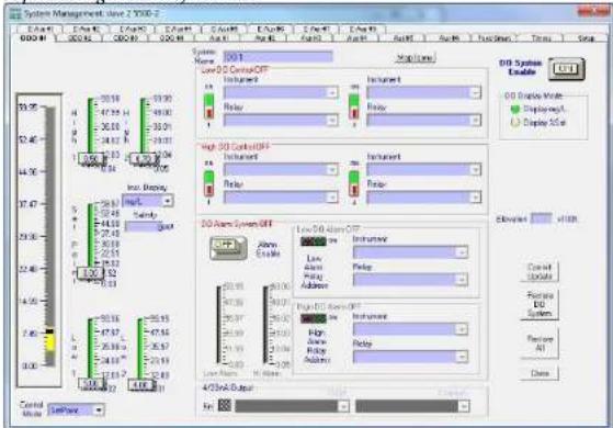
Notes:

- Always manually poll the 5X00 after uploading configuration changes and verify that the uploaded information is retained at the 5X00. When configuration changes are uploaded using AquaManager at the same time configuration changes are being made by a user in the menus on the 5X00, AquaManager uploads may not be saved depending on the timing of keystrokes at the 5X00.
The Run Screen must be displayed during normal operation. If the 5X00 is not at the run screen during AquaManager uploading, pressing Exit Menu at the 5X00 may \only save certain configuration changes.

See Chapter 5 AquaManager - page 197 and AquaManager online help for additional information.
Timers
The 5X00 has four daily ten event timers. Timers can be configured to control various hardware devices. In addition, there are four Feed Smart ^™ feed timers.
Timers 1-4
Menus → Timers→Timer 1-4
Configure up to 40 daily timer events using the 10 events of DailyTimer systems 1-4. Timer events occur on a daily basis until either the start time is cleared, the timer
system is disabled, or the relay is disabled. Timer icon 📊 displays at systemwide icon location at the Run Screen when timer relay is active.
Directions to Configure Timers 1 - 4

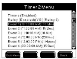
Please review - Use AquaManager to configure sensor systems - page 150.
- Install and wire timer device(s) or any networked 5X00 instrument - page 54.
OR
-
Wire relay output device(s) to REM - see IOEM/REM Safety and Installation guide>Chapter 3>Step 4>Wire REM Relay Outputs.
-
Enter Timer 1-4 menu
Menus → Timers
-
Use ▲ and ▼ to scroll and highlight submenus.
-
Press to select.
-
Enable and configure submenus.
-
Press Exit Menu to save configuration and return to Run Screen.
Notes:
Timer system must be enabled in order to energize the configured timer relay.
- Press Mag's to display timer events.
- Timer events with overlapping times occur as follows. Example - event 1 starts at 10:15 for 25 minutes, event 2 starts at 10:25 for 25 minutes; relay turns on at 10:15, relay turns off at 10:25, relay turns on at 10:25, relay turns off at 10:50.
- Configure "0" duration time to disable any of the 10 timer events.
- Timers configured over 86399 seconds (seconds in a day) are not valid.
- If a timer is active (relay energized), the timer is NOT recalculated when the 5X00 time and/or date is changed. Once a timer has been turned on, it runs for it's configured duration and does not reset it's run time based on changes made to 5X00 time. Example - Timer 1, event 1 is configured to come on at 9:00am for 10 minutes. Timer relay energizes at 9:00am. At 9:05am, the 5X00 unit time is changed to 10:05am (for daylight savings adjustment). The timer relay will de-energize after five additional minutes. Unit time will be 10:10am. The event log will reflect the unit time when the event occurred. In this example, 9:00am for the start time and 10:10am for the end time.
- If a timer is active (relay energized) and 5X00 is put on service hold, the relay will not reenergize after service hold expires regardless if timer time has not expired. There is only one "on" time for all timers. Turn the 5X00 off, then on, to reset the timer system. A timer relay will energize for the configured time duration and not for the remainder of time prior to service hold. Example - timer relay 1 is configured to start at 11:00 am for one hour. Service hold is enabled and configured for 5 minutes. The timer relay energizes at 11:00 am. At 11:15 am, the 5X00 is put into service hold. Timer relay 1 dc-energizes. At 11:20 am, the service hold time expires. The 5X00 is power cycled and the timer relay energizes after 30 seconds. The timer relay de-energizes at 12:20 pm and not at 12:00 pm which would have been the original off time if the unit had not been placed in service hold.
- Energized timer relays de-energize at downloader. The relay will reenergize after a power cycle following the downloader if the timer system is still active.
Timer relay will energize for entire configured duration time and not for the remainder of time prior to being placed in downloader. There is only one "on" time for all timers. Example - timer relay 1 is configured to start at 11:00 am for one hour. The timer relay energizes at 11:00 am. At 11:15 am the 5X00 is put into downloader. Timer 1 relay de-energizes. Timer 1 relay re-energizes 30 seconds after a power cycle following the downloader (at approximately 11:24 am). The timer relay de-energizes at 12:24 pm and not at 12:00 pm which would have been the original off time if the unit had not been placed in downloader.
- If power fails when a timer is energized and the power is restored when the timer system is still active, the timer relay will energize for the timer duration and not for the remaining original timer cycle. Example - timer one is configured to start at 10:40 for one hour. The power fails at 11:30. Power is restored at 11:35. The timer will energize for one hour, not the remaining 5 minutes of the original timer cycle.
- When the timer relay is energized after the timer duration is changed, the timer relay de-energizes and reenergizes for the newly configured duration and not for the remaining original timer duration. Example - timer one is configured to turn on at 8:30 am for 10 minute duration. Timer one relay energizes at 8:30 am. At 8:35 am, timer one duration is changed to 20 minute. Timer one relay de-energizes at 8:35 am and re-energizes for the newly configured 20 minute duration.
- When the timer start time and duration are reconfigured and fall within the current 5X00 unit time, the relay energizes for the entire duration. Example - The 5X00 unit time is 8:30 am. Timer one is configured to turn on at 8:00 am for one hour. The timer relay will energize at exit to run screen and will remain energized for one hour. The 5X00 does not use the system clock to calculate duration in this case. The following day, the relay will energize at 8:00 am, and de-energize at 9:00 am.
- There is a 30 second delay at power up before timers become active.
- Timer relay off times drift by < .2% . when duration is longer than 5 minutes. The drift increases the relay 'on' time.
Feed Smart ^tm Timers 1-4
Menus → Timers→Feed Smart™ Timer 1-4
The 5X00 has four feed timers. In order to configure feed timer(s) correctly, it is important to understand how the 5X00 functions based on the feed timer configuration. The Feed Smart™ Timer system must be calibrated prior to use. For proper operation, the Feed Timer System requires the user to enter the total amount of food to be dispensed, number of feedings to dispense the food, and a defined time period within which the feedings will occur. The Feed Timer can be configured to operate for any or all days of the week and includes continuous or timed feeding

icon is displayed
modes, FCR (feed conversion ratio), and sensor options. 📄 icon is displayed when any Feed Smart™ timer relay is energized.
The following definitions are used in regard to the Feed Smart™ Timer system:
- feed cycle - amount of time that all feeds occur in:
- continuous - feedings occur over 24 hour per day period;
- timed - feedings occur only between configured start and end times;
- feed duration - length of time feeder relay is energized;
- feed interval - length of time between feedings.
Optional Sensor control reduces the amount of food dispensed if DO or temperature measurements are "out of range" per user defined configuration. The FCR (feed conversion ratio) feature automatically computes and increases the daily amount of food dispensed per FCR configuration.
Notes:
- It is important that the 5X00 be configured with valid data. The feeder system will not operate properly if, for example, the daily weight of food is greater than can be dispensed in the defined feed cycle.
- Disable the feed timer system when changing configuration and/or when performing a calibration. Enable the feed timer system after configuration changes and/or calibration has been done. The feed timer system recalculates
duration and interval times based on the new configuration. Press Exit Merit after disabling the feed timer system and before making configuration/calibration changes.
Feed Mode
Continuous
Menus → Timers → Feed Smart Timer → Feeder → Feed Mode → Continuous
When the feed timer is configured for continuous feed mode, feedings occur throughout the day. Feed duration and interval are determined by the daily total weight of food, number of feedings, and test calibration data. Optional Sensor control and FCR configuration can also effect feed duration.
| Example of Feed Timer Configuration and Test Calibration Data: | |||
| Feed ModeContinuous (86500 seconds in 24 hours),feed timer sensor control is disabled | daily weight500 units | daily feedings100 | test calibration data10 units per 30 seconds |
| The 5 X00 determines feed duration and feed interval for the above feed cycle as follows: | |||
| units fed per feeding: | 500 ÷ 100 = 5 units per feed | ||
| feed time duration for each feeding: | if 10 units feed in 30 seconds, then 5 units will feed in 15 seconds 30 × 5 ÷ 10 = 15 | ||
| determine total time feed relay will be energized over 24 hour period: | 15 units X 100 feeds = 1500 seconds | ||
| determine feed interval: | 86500 - 1500 = 84900 ÷ = 100 (number of feeds) = 849 seconds, 60 = 14.15 minutes, or 14 minutes and 9 | ||
Notes:
Once Continuous feed has been configured, the 5X00 determines any remaining feeds for the 24 hour period ending at 23:59. In continuous feed mode, the feed cycle always begins at 00:00 (midnight). Start and End time fields are not available for Continuous feed mode.
- In continuous feed mode, feeding(s) will end after the last completed feeding that ends prior to 11:59 pm (23:59) of an enabled day when crossing midnight to a disabled day. Feeding(s) will resume at 12:00 am (00:00) for the next enabled day.
Timed
Menus → Timers → Feed Smart Timer → Feeder → Feed Mode → Timed
Feedings occur only during the start and end times on "enabled" days of the week. In timed mode, the 1st feeding occurs at the start time of the feed cycle. The last feeding completes by the end time. Feed duration and interval are determined by the daily total weight of food, number of feedings, and test calibration data. Optional Sensor control and FCR configuration also effect feed duration.
| Example of Feed Timer Configuration and Test Calibration Data: | |||
| Feed ModeTimed, Start Time: 8 am, End Time: 10Afeed timer sensor control is disabled | daily weight500 units | daily feedings5 | test calibration data10 units per 30 seconds |
| The 5X00 determines feed duration and feed interval for the above feed cycle as follows: | |||
| units fed per feeding: | 500 ÷ 5 = 100 units per feed | ||
| feed time duration for each feeding: | if 10 units feed in 30 seconds, then 100 units will feed in 300 seconds 30 × 10 = 300 | ||
| Total feed duration over 2 hour period | 300 seconds X 5 feeds = 1500 seconds | ||
| determine feed interval: | 7200 seconds (seconds in 2 hours) - 1500 (feed duration seconds for 2 hour) = 1140 seconds ÷ 60 = 19 minute intervals | ||
Notes:
- If a timed feed cycle includes feed times that cross midnight, the feed cycle ends prior to 11:59 pm (23:59) of the enabled day when crossing midnight to a disabled day. Feeding(s) will resume on next enabled day. Example - if Tues through Sat are enabled days and the start time is configured for 10:00 pm (23:00) and the end time is configured for 01:00. On a Saturday, the feed cycle would start at 10:00 pm (23:00). The last feed occurs by 11:59 pm (23:59) on Saturday since Sunday is a disabled day. The next feed occurs at 12:00 am (0:00) on Tuesday. This feed cycle would end at 01:00 on Tuesday. No feeding occurs Monday, because Monday is a disabled day.
- The Feed timer will not operate properly if the start date is set prior to January 1, 2007.
Daily Weight
Menus→Timers→Feed Smart™ Timer→Feeder→Daily Weight
The daily feed amount is the total weight of food that will be dispensed over the feeding cycle. The value is user selectable from 1 to 100000. The Feed Timer system divides the total daily feed amount by the number of daily feedings and uses the calibration/test data to determine feed duration and interval times.
Daily Feedings
Menus → Timers → Feed Smart™ Timer → Feeder → Daily Feedings
Configure the number of feedings to occur in feed cycle. The value is user selectable 1–255.
FCR
Menus → Timers → Feed Smart™ Timer → Feeder → FCR
The optional FCR (feed conversion ratio) feature automatically increases the amount of food dispensed over a feed cycle. The increase in the amount of food is based on the user configured increase in biomass over a 24 hour period. Biomass and daily (feed) weight amounts are adjusted by the 5X00 prior to the 1st feed "on" time of a scheduled feed cycle occurring after midnight.
Notes:
With FCR enabled and properly configured an event occurs when the 5X00 time crosses midnight. See below.
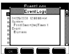

Biomass
Menus → Timers → Feed Smart™ Timer → Feeder → FCR → Biomass
Enter the total weight of livestock being fed at the time FCR is enabled. The value is user selectable 1 to 100000.
Feed % (of) Biomass
Menus → Timers → Feed Smart Timer → Feeder → FCR → Feed % Biomass
Enter the percentage of the total livestock weight (biomass) that will be used to determine the daily feed weight. The value is user selectable 0.0–99.9%.
Daily (Feed) Weight
Menus → Timers → Feed Smart Timer → Feeder → FCR → Daily Weight
Configure the initial daily feed weight by multiplying the biomass amount by the Feed % Biomass percentage (the 5X00 will not calculate the initial amount). Example—if the biomass is 1000 and the feed % biomass is 3%, the initial daily feed weight amount is 30. On each following day, the 5X00 will use the biomass value along with the feed % biomass to calculate the new daily feed weight amount.
Note:
- The initial daily weight value must be calculated as described above. Configuring an invalid initial daily weight will result in incorrect biomass and daily weight calculations when the 5X00 crosses midnight.
FCR Factor
Menus → Timers → Feed Smart Timer → Feeder → FCR → FCR Factor
Enter the ratio of the amount of food required versus the corresponding increase in fish weight (biomass). This value is used to automatically increase the biomass amount—as shown in the example below.
| FCR example | |||||||
| Day 1 | Day2 | Day 3 | Day 4 | Day 5 | Day 6 | Day 7 | |
| Biomass | 1000 | 1020 | 1040 | 1061 | 1082 | 1104 | 1126 |
| Feed % Biomass | 3% | 3% | 3% | 3% | 3% | 3% | 3% |
| Daily Feed Amount | 30 | 30.6 | 31.2 | 31.8 | 32.5 | 33.1 | 33.8 |
| FCR Factor | 1.5 | 1.5 | 1.5 | 1.5 | 1.5 | 1.5 | 1.5 |
| 1/FCRX Feed Amount | 20 | 20.4 | 20.8 | 21.2 | 21.6 | 22.1 | 22.5 |
| New Biomass | 1020 | 1040 | 1061 | 1082 | 1104 | 1126 | 1149 |
Sensors
Menus → Timers → Feed Smart Timer → Feeder → Sensors → Disabled/Enabled
→DO Low/High/DO % Change
→Temp Low/High/Temp % Change
Changes in water conditions affect the amount of food fish eat which in turn affects fish growth. With the sensor feature enabled, the feed timer system will verify that DO and temperature values are within user configured ranges. This verification is done immediately prior to starting each feed duration in a feed cycle. If values are reported that fall outside acceptable configured ranges, the feed timer relay energizes for a shorter period (user configured percentage) thereby reducing the amount of food that is dispensed. Feed timer sensor ranges are independent of sensor setup configuration ranges. For timed feed cycles, feed interval for the entire feed cycle is determined by the duration of the first feed.
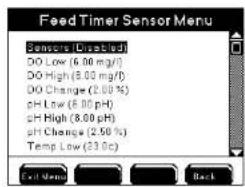
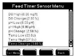
Example - The feed timer is configured as follows: sensor temperature low value is 25.1°C, feed timer temperature change is 9%, timed feed mode, six feeds, daily weight 2 units start time 8A, end time 9A, six 9.999 second feeds of .3333 units each to occur at 9 minute 50 second intervals without sensor reduction. Prior to 8A feed cycle, the start temperature value is reading 24.9°C. Feed duration of 9.999 seconds will be reduced by approximately 1 second (9%) because of the "out of range" temperature value.
Notes:
5400 - 5400 - Feed Timer temperature sensor value is always taken from the DO system configured temperature source.
5500 - Feed Timer temperature source is always taken from the ODO temperature sensor regardless if temperature system is configured for an aux temperature sensor.
DO Low/Temp Low
Enter the lower limit of the sensor range where no feed reduction will take place.
DO High/Temp High
Enter the high limit of the sensor range where no feed reduction will take place.
DO Change/Temp Change
Enter the percent reduction in feed weight that will occur for "out of range" enabled feed timer sensors. Results from all out of range sensors are added. To disable a sensor value from affecting feed duration configure 0.0% as the % change for that sensor.
Calibrate
Menus → Timers → Feed Smart™ Timer → Feeder → Calibrate
Calibrating the feeder is essential for proper operation of the feed timer system. Feed timer calibration is required to establish the amount of food dispensed over a certain period of time. The 5X00 will base feed cycle duration times on the last saved calibration value.

Calibrate Feed Smart™ Timer
- Install and wire feed timer device. See wire relays - 54.
- Enable Feed Timer.
Menus → Timers → Feed Smart TM Timer → Feed Timer → Enabled - Assign feed timer relay.
Menus → Timers → Feed Smart ^tm Timer → Relay -
Calibrate feeder
Menus → Timers → Feed Smart ^tm Timer → Calibrate -
At numeric keypad, enter test run time the feeder relay will energize.

-
Press for OK timer relay to energize for configured run test time. Countdown of relay "on" time is displayed.
-
When run time expires, the relay de-energizes. Enter the amount of food dispensed at the Measured Weight screen.
-
Press Exit Menu to save settings and return to Run Screen.
Notes:
- Since feeders and food size vary, run several calibrations and enter the average weight at the last calibration. If feeder or feed type is changed, recalibrate the feeder.
- If no test/calibration has been performed or if the results have not been saved, the 5X00 will be unable to perform any feeding(s) because there will be no reference to determine the rate at which feeding(s) will occur.
- Stored calibration data is available from the AquaManager program.
- If feed timer units change, the feeder must be recalibrated.
- If an incorrect value is entered and saved, another calibration must be performed.
- Disable feed timer system when performing feed timer calibration, de-energizing any active feed timer relay.
- After calibration is complete, press Exit Menu to Run Screen. The Feed timer system resets based on new calibration configuration.
- Feed Timer calibration cannot be done using AquaManager.


AquaManager and the Timer Menu
Most Timer menus can be configured using AquaManager. After polling the 5X00 node, use "Systems Management" to view and upload 5X00 configurations. Select the Feed Smart ^™ and Timers tabs to view and change configuration.

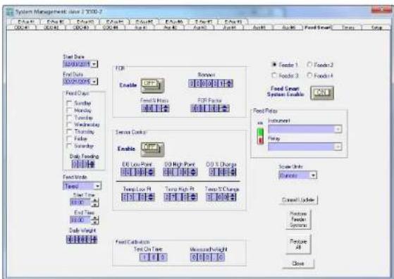
Notes
- Always manually poll the 5X00 after uploading configuration changes and verify that the uploaded information is retained. When configuration changes are uploaded using AquaManager at the same time configuration changes are being made by a user in the menus at the 5X00, AquaManager uploads may not be saved depending on the timing of keystrokes at the 5X00.
- The Run Screen must be displayed during normal operation. If the 5X00 is not at the run screen during AquaManager uploading, pressing out here at the 5X00 may only save certain configuration changes.
See Chapter 5 AquaManager - page 197 and AquaManager Online Help for additional information.
Control Menu
Press Control Run Screen to display a list of energized sensor and aux 5X00 system relays. The Control menu identifies the active sensor or aux system and control and/or alarm condition. See Control mode and alarms - page 152 for additional information.

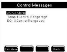
Notes:
- Press Meg's to display time stamped detail of control and alarm relay(s).
- Alarm message appears at the Control menu for aux and sensor systems when alarms are enabled regardless if an alarm relay is assigned.
- Active timer (10 event timer and feed timer) systems are not displayed at control menu.
- General alarm systems are not displayed at the Control menu regardless if general alarm relay is enabled.
- Use ▲ ▼ to scroll list when scroll bar appears at window.
When no 5X00 control or alarm system(s) are active, the below screen is displayed.
Msg's Menu
Calibration, Sensor, and Event logs contain 5X00 system information. The 5X00 Sensor log stores 2000 records. The Calibration log stores 500 records. The Event log stores 1250 records. Once the log memory is full, the oldest records are overwritten with more recent records. The number shown in ( ) at the Msg's menu reflects the total number of records in the log. The 25 most recent records for each log are
displayed at the Msg's menu. Use ▲ ▼ to scroll and press ← to view time stamped detail record.

Use AquaManager to capture all records from 5X00 logs and store them to a PC database. Polling times should be determined by logging intervals. Example - if the sensor log is recording values every minute and the sensor log holds 2000 records, polling should occur at least every 33.3 hours. This allows for all records to be saved to the PC before being overwritten on the 5X00. Set the data log interval so that analyzing data based on the configured interval will be helpful. Poll at intervals that don't result in gaps in data.

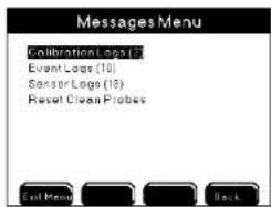
A Reset Clean Probe message will appear at the Msg's Menu if the clean probe timer expires. Selecting "Yes" at "Are you sure?" resets the clean probe timer to the user configured number of days.

Note:
- User configured sensor and relay names do not appear in log menus.
Calibration Logs
Calibration logs store sensor calibration data. Calibration logs are date and time stamped and contain sensor and calibration information for completed calibrations.
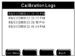


Certain calibration data is not available at the 5X00. Use AquaManager to view and save calibration data to a PC. In addition to sensor system, time, date, and calibration method, AquaManager calibration logs include user input 1, user input 2, and the original and new slope/offset information when applicable.
Event Logs
Control, Alarm, and Timer relays assigned to 5X00 systems create events when they energize and de-energize. In addition, AC power fail, ethernet failure to initialize errors and mode network failures create events. These events are recorded in the Event log. Events identify the 5X00 system, arc time stamped, and record relay on and off times (if applicable). The General Alarm does not create an event or control message unless a General Alarm relay is enabled.


Note:
Enable event logging in the System menu. See Event Logging - page 120 for additional information.
- E-Aux system event logs are stored at the local instrument whose E-Aux
system is being used and not at the device whose output is creating the event. For example - if an IOEM channel 2, whose slave address is 4, is configured as an E-Aux temperature input for a 5200A (slave 14), and a low temperature control relay output for this slave 14 is configured to a 5500 (master), the 5200A (slave 14) and not the master 5500 records the low temperature control events.
Sensor Logs
Enabled systems record sensor data based on data logging menu configuration. Sensor logs identify sensor system, are date and time stamped, and record sensor value at user configured intervals.
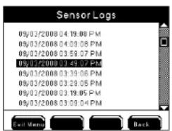

Notes:
- Data logging must be enabled in the System Menu. See Data Logging menupage 118 for additional information.
- 5X00 E-Aux system datalogs are not visible at the instrument.
- AquaManager datalogs must be used to view E-Aux system datalogs;
Svr Hold softkey Button
When servicing sensors or doing tank maintenance, it may be necessary to shut off all systems (including relays) because sensor values will not be accurate. Press
Svc Hold at Run Screen to enter Service Hold menu. When in Service hold, all relays are de-energized until the Service Hold time expires. The Service Hold time is user selectable. Enable and configure service hold time at Menus → System→Service Hold - 147.. After service hold time expires or is cancelled, sensor and aux systems are reset causing relays to energize/de-energize based on the system value/condition. Timer systems are not reset. To reset timer systems, turn power off and then on to the 5X00. Press Exit Menu to exit Service Hold.
The Run Screen displays a clock count down of the Service Hold remaining time.
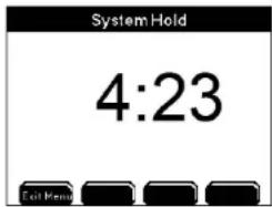
Notes:
- If a timer is active (relay energized) at service hold, the relay will not reenergize after service hold expires regardless if timer time has not expired. There is only one "on" time for all timer systems.
- Entering Downloader mode places 5X00 into Service Hold.
- "Inst. Service Hold" is displayed on any AquaManager map icon associated with an instrument in Service Hold. AquaManager alarm emails are not sent for any alarm condition for a 5X00 that is in Service Hold.
- 5X00 alarm emails are not sent during service hold.
5 AquaManager
-Installing -Registration
Installing AquaManager
AquaManager provides data logging, graphing, autopolling, mapping, system configuration control, and displays near real-time sensor and aux input values and conditions* at the desktop PC. AquaManager is a valuable tool for remote and local access applications. An extensive online Help system is provided with AquaManager.
*Near real-time - The AquaManager map is updated several times a minute as AquaManager constantly communicates with the nodes during Autopolling using SMS commands. This results in displaying near real-time sensor and aux input values on the map.
One copy of AquaManager per machine is required.
PC requirements and features
AquaManager is a 32-bit Windows application and will run on Windows 2000/XP/Vista/Windows 7 operating systems 32-bit and 64-bit. AquaManager has the following system requirements on your PC:
PC capable of running Windows 2000
Microsoft Windows 2000 (workstation or server) OR XP (home or professional SP3) OR Vista (SP1) OR 7
- VGA display card
- CD-ROM Drive
- Total RAM installed 16 Megs or greater
- 100 MB of free hard-disk space
- Internet Explorer 7.0, or higher
- Adobe Flash 10b, or higher
- Administrator privileges on PC where application is being installed

Recommendations:
- Total RAM installed 64 Megs or greater
- 300 MB of free hard-disk space
- latest versions of Microsoft including O/S
- latest version Internet Explorer for AquaManager HTML Help
Software Installation
- Run AquaManager.exe on the CDROM and follow the instructions in the installation setup.
- Refer to the README.txt file on the CDROM for additional information on installation and use of AquaManager application.
- Open application and register. The registration number code is located on the back of CD case.

YSI 5X00
199
AquaManager
See AquaManager Online Help for detailed application configuration information. Before the node can be accessed using AquaManager, perform the following:
- Create, or Open network;
- Insert group;
- Insert node(s);
A. Determine communication method;
B. Obtain 5X00 serial number(s); - Poll node to obtain current node configuration;
- Complete configuration of node and Aquamanager features for your application.
AquaManager Windows
Use the Explorer and Node Screens to access configuration forms. Certain configuration forms can be assessed in multiple ways. Access to configuration forms is provided below.
Explorer Window
The Explorer Screen is displayed when AquaManager is launched. At the Explorer Screen, the network tree is displayed. The tree includes network, group, and node folder(s), along with node systems that are used for mapping. The tree is represented in hierarchical format.
AquaManager
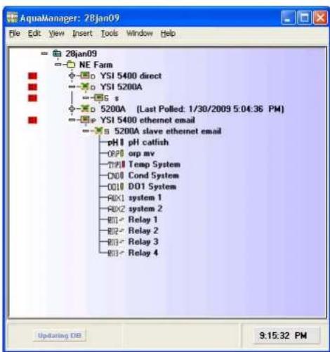
The following configuration and tasks are performed from the Explorer Screen:
- create, open, and export networks
- insert and configure nodes and groups
- edit and view map
- configure system wide properties
- print tree and printer setup
- exit program
-cut, copy, and find node(s) - delete node or group
- sort nodes in group
- expand and collapse tree view
- access network log files
- insert manual event and manual data into node
- password administration
- launch autopoller
- generate reports
- manual database maintenance
- launch update firmware utility
- configure window display format
AquaManager
- access AquaManager Help
- check for AquaManager software updates
- AquaManager about information
Node (Graph) Window
Double click on a node in tree at the Explorer Screen to open a Node window. A graph is displayed based on the sensor log data received from the last poll. Use graph management and Node Window options to configure the graph display.

The following configuration and tasks are performed from the Node Window: - view and configure node properties
- print graph and printer setup
- close node window
- copy graph to clipboard
- insert manual event
- graph management
- customize graph settings
- clear graph overlays
- view data, calibration, event, & configuration event logs
- restore Node Window size to include access to systems management and poll node buttons
- Systems Management access - viewing and uploading configuration to 5X00
AquaManager
- Graph Display options
- Manually poll node button
- Current data is displayed at the top of the graph during a manual poll
Systems Management
To open Systems Management, click on the Systems Management button located to the right of the graph in the Node Window. Use the tabs to view and upload configuration to node. The node configuration displayed is based on last poll.

The following configuration and tasks are performed from Systems Management forms:
- view and configure node sensor and aux systems
- view and configure node timer and feed timer systems
- view and configure most node systems (5X00 system menu)
- configure node mapping icons
Notes:
- Always manually poll the 5X00 after uploading configuration changes and verify that the uploaded information is retained. When configuration changes are uploaded using AquaManager at the same time configuration changes are being made by a user in the menus at the 5X00, AquaManager uploads may not be saved depending on the timing of keystrokes at the 5X00.
- The Run Screen must be displayed during normal operation. If the 5X00 is not at the run screen during AquaManager uploading, pressing out here at the 5X00 may only save certain configuration changes.
Database Management
For optimal operation and safeguarding, compact and back up the AquaManager database. Uncompacted Access database(s) may become >1GB when polling large networks and when polling nodes with large data logs. Compact the database from the Explorer Window Tools>Database Maintenance>Compact Database or from the System Wide Properties>Gen. Settings tab.
Configure an automatic weekly backup from the System Wide Properties>Database Backup tab.

Note:
Database Auto-Compaction must be enabled in order to access the Backup enable box.
Autopoller
Autopoller is designed to poll node(s) at an interval specified by the user. When the node(s) is polled, new log records and the node configuration are saved to the AquaManager database. Autopoll must be running for the AquaManager email and mapping to operate.
Launch Autopoll at the Explorer Window>Tools>Launch Autopoller.
![AcquiseManager: new 3dec.06 File Edit View Insert Cost Window Help Password Administration Mapping AutoPolar Launch AutoPolar Clear AutoPolar Tags Set AutoPolar Tags Instruments Tools [0:43:47 AM] Operating DO 11:57:02 AM](/content/2026/05/935752/images/870fd159eb5edd953201db9eae88da7daf4db35f0a27f2854b5c081b633be164.jpg)
The Autopoller Window opens when Autopoller is launched.
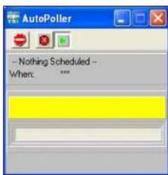
Mapping
Create a network map to display current conditions* for 5X00 nodes at PC running AquaManager. Map icons are configured to represent nodes, node systems, and relays. Map icon images change based on system condition(s). For example, a green icon is displayed when DO-1 is in acceptable operating range, a yellow icon is displayed when DO-1 system is in control range (when enabled), and a red icon is displayed when DO-1 system is in alarm range. This provides a quick visual of system conditions at the PC.
AquaManager
*Near real-time - Map is updated several times a minute as AquaManager constantly communicates with nodes during Autopolling.
Node mapping is available for direct and TCP/IP node communication types.
The following figure is an example of an AquaManager map.

AquaManager Alarm Emails
The PC running AquaManager can be configured to send an alarm email when data received from the node is in alarm range. The alarm range or condition is based on the node configuration. The node configuration is stored in the network database and is verified and updated at each Autopoll SMS communication interval. Autopoller must be running for AquaManager to generate alarm emails. Run Autopoller 24/7 to ensure that alarm emails are sent.
For the AquaManager alarm email to function properly, it may be necessary to send a test email to each email address configured in the Email Alarm List in the Node Properties window. Test emails can be sent in the AquaManager Properties window under the Autopoller tab.
6 Maintenance
-Sensor Calibration Checks
-Sensor Maintenance
-Sensor Storage
-Charging DC batteries
-AquaManager database
Maintenance
It is important to remember that the quality of data is dependent on three factors directly related to the probe:
- General maintenance at the physical deployment site of the probe.
- A well-defined quality assurance program that is carried out on a regular basis to ensure that the sensors are performing properly.
- Proper periodic calibration and maintenance of the specific sensors.
This chapter is designed to provide help in these important areas by providing maintenance tips, help in implementing a quality assurance protocol, and suggested service methods and intervals for the sensors.
Probe Maintenance at the Deployment Site Algae and Debris
A common problem most likely to be encountered with regard to the overall probe deployment is fouling from algae (and other debris). Algae will inevitably collect on any object immersed in water and, unless periodically removed, it can inhibit the sensor's measurement. Once algae build-up occurs on the sensors and/or probe guard, it isolates the sensor's environment from the sample stream. To avoid or minimize this problem, it is necessary to periodically remove the algae from the probe guard and sensors.
Minimizing the Effect of Algae and Debris
The collection of algae on the probe and the frequency of cleaning can be minimized by deploying the probe so that it is angled with (rather than against) the current of the stream. This deployment method will maximize the chances of the algae being swept free of the probe rather than collecting on it.
Remember that no matter what precautions are taken, debris will still collect on the probe and the fouling will have to be removed by periodic cleaning. Cleaning will be easier if the probe mounting method allows for easy removal and replacement of the probe. A little extra time spent on implementing a good mounting arrangement using the optional probe mounting kits will save a lot of time in subsequent cleaning operations.
The frequency with which you will have to remove fouling from the probe varies with the type of water being monitored and the physical deployment of the probe. The need for cleaning can usually be ascertained by visual inspection. You can do no harm by excess cleaning so it is best to remove and clean the probe if any significant fouling is suspected.
Calibration Checks
The sensors are of high quality and should exhibit excellent performance in excess of the warranty period warranty, see 257. However, the dissolved oxygen sensors will inevitably show some drift during deployment due to physical changes of the electrodes, minor fouling of the sensor surfaces, or both of these factors. Inconsistent (fluctuating or noisy) DO sensor readings signal the need for maintenance procedures specific to those sensors. With these factors in mind, it is imperative that you establish and carry out regular quality checks of the sensor readings to ensure that sensor values are being reported accurately and within specifications. The quality checks can help determine when sensor maintenance or calibration is required.
Recommended Quality Assurance Protocol
This product has been designed and tested to provide trouble free service. However, as with all microprocessor based products, there is potential for failure which could cause loss of control functions. Proper QC (Quality Control) procedures can reduce the potential for failure.
It is recommended that you carry out the following quality assurance program weekly during the initial use of the 5X00 system. After several weeks of this program, you should be able to ascertain if this frequency is appropriate for your application. If only minimal drift is observed, then the frequency of quality checks can be decreased. The procedure is relatively simple and should take only about 20 minutes to complete.
- Take the following items to the deployment site:
- bucket for clean water to rinse sensors
- small brush supplied with the conductivity sensor
- calibration/storage cup supplied with the probe/cable assembly
- solution and/or secondary instrument to verify values displayed by sensor. See Calibration starting on 81.
- latex gloves
- Disable any system control and/or alarm relays that may become active as a result of value(s) generated during the validation process. For example if a DO system is configured to energize a control low relay at ≤ 5.5 mg/L and sensor validation is being made by placing the sensor in mg/L solution ≤ 5.5 mg/L, the control low relay will energize and may adversely affect the DO water system based on the mg/L solution value and not the system stream.
- Place the 5X00 in Service Hold mode. See 147 and 196 for Service Hold information.
Maintenance
- Remove the probe from the sample stream.
- Remove the probe guard from the 5422 and 626250 probes.
- Manually remove any debris from the sensors and then rinse the sensor carefully in a bucket of clean water, being very careful not to damage the sensor and membrane or cap.
- Inspect the dissolved oxygen membrane for obvious holes or tears. Do not remove the membrane at this time.
- Replace the probe guard on the 5422 and 626250 probes.
- Exit Service Hold if Service Hold timer has not expired. See pages 147 and 196 for Service Hold information.
- Place the sensor in its calibration environment, i.e. 100% water-saturated air. This can be accomplished by placing the 5422 and 626250 sensor in the calibration/storage sleeve containing a moist sponge. For the 5420 or 5421 sensor, place the sensor in air removing any water droplets on the membrane.
- Wait about 5 minutes for temperature equilibration and then record the dissolved oxygen reading in percent air saturation as shown on the 5X00 display.
- If the dissolved oxygen readings show minimal calibration drift (i.e., within about 5% of the correct value) and the readings are stable, proceed to Step #14. If excessive drift is noted or the readings are jumpy, replace the membrane cap as described in the instruction sheet included in the Membrane Kit.
- After replacing the membrane, calibrate the DO sensor. See calibrate DO sensor starting on page 83.
- Place the probe back in the sample stream and continue monitoring.
- Test all control and alarm relays for proper operation.
NOTE: This procedure does not include quantitative data taken with regard to the temperature sensors. The temperature sensor only fails in very rare circumstances and, if it does fail, the temperature readings will seem unreasonable for the current conditions. In the unlikely event that the temperature sensor shows unusual and/or jumpy readings, it will need to be checked by a YSI authorized service center. No user service is possible.
Alternative Quality Assurance Protocol (quick check and adjustment)
An alternative protocol, complementary to the quality assurance program described above, can be carried out by comparing the current dissolved oxygen reading shown on the 5X00 with those taken by a recently calibrated hand held instrument. For dissolved oxygen, the probe of a handheld DO instrument can be placed in the
Maintenance
stream near the 5X00 probe. If a comparison of the readings from the recently calibrated DO instrument and the 5X00 indicates calibration drift, the 5X00 can be recalibrated. Note - this comparison should only be used to determine if a calibration is necessary once the 5X00 probe has been cleaned of all algae and other debris. If a gross variation is observed between the two instruments (>1 mg/L), it is likely that maintenance is required on the 5200 DO sensor.
Sensor Care and Maintenance
Periodic DO sensor electrode cleaning and membrane changes are required.
DO Sensor
The DO sensor requires periodic membrane changes and electrode cleaning. For best results, YSI recommends that the electrolyte solution and the membrane cap be changed at least once every 30–90 days (YSI 5420, 5421 and 5422). Refer to the instruction sheet included with the membrane kit for specific instructions on changing a membrane. YSI recommends replacing the sensor cap (ODO 626250) about once per year. The sensor cap should also be replaced if it is cracked or damaged. The instruction sheet shipped with the replacement ODO sensor cap includes the calibration coefficients specific to your sensor cap.
Notes
- Membrane life depends on usage. Membranes will last a long time if installed properly and treated with care. Erratic readings are a result of loose, wrinkled, damaged, or fouled membranes, or from large (more than 1/8" diameter) air bubbles in the electrolyte solution. If erratic readings or evidence of membrane damage occurs, replace the membrane and the electrolyte solution.
- If the membrane is coated with oxygen consuming (e.g. bacteria) or oxygen producing organisms (e.g. algae), erroneous readings may occur.
- Chlorine, sulfur dioxide, nitric oxide, and nitrous oxide can affect readings by behaving like oxygen at the sensor. If you suspect erroneous readings, it may be necessary to determine if these gases are the cause.
YSI 626250 sensor maintenance
The Sensor Cap should be kept clean since some types of fouling may consume oxygen which could affect the dissolved oxygen measurements. To clean the Sensor Cap, gently wipe away any fouling with a lens cleaning tissue that has been moistened with water. Do not use organic solvents to clean the Sensor Cap. Using an organic solvent to clean the Sensor Cap may cause permanent damage to the cap. For example, alcohol will dissolve the outer paint layer and other organic solvents will likely dissolve the dye in the cap.
Before reinstalling the sensor cap, make sure that the cavity is completely dry before proceeding with the installation. If water is found, dry the cavity with lens cleaning tissue. Finally, clean the clear window on the end of the probe with lens cleaning tissue.
YSI 5422 Electrode Maintenance
The gold cathode and silver anode require cleaning about once or twice per year. Perform the following cleaning procedures if, after a DO membrane change, the DO readings are erratic and/or a good calibration can not be performed.
Silver Anode Cleaning
After extended use, a thick layer of AgCl builds up on the silver anode reducing the sensitivity of the sensor. The anode must be cleaned about once or twice per year (depending on use) to remove this layer and restore proper performance.
The cleaning can be chemical and/or mechanical:
Chemical Cleaning: Remove the membrane cap and soak the electrodes in a 14% ammonium hydroxide solution for 2 to 3 minutes, followed by a thorough rinsing with clean water. The anode should then be thoroughly wiped with a wet, lint free cloth to remove the residual layer from the anode.
Mechanical Cleaning: Sand off the dark layer from the silver anode with 400 grit wet/dry sandpaper. Wrap the sandpaper around the anode and twist the sensor. Rinse the anode with clean water after sanding, followed by wiping thoroughly with a wet lint free cloth.
Note - After cleaning, install a new membrane cap with fresh electrolyte and then perform a calibration. Refer to the instruction sheet included with the Membrane kit for instruction on how to replace a membrane.
Turn the instrument on and allow the system to stabilize for at least 30 minutes. If, after several hours, you are still unable to calibrate, contact YSI Customer Service.
Gold Cathode Cleaning
For correct sensor operation, the gold cathode must be textured properly. It can become tarnished or plated with silver after extended use. The gold cathode can be cleaned by using 400 grit wet/dry sand paper. This should be done about once or twice per year.
Using the sand paper provided in the YSI 5238 Probe Reconditioning Kit, wet sand the gold with a twisting motion about 3 times or until all silver deposits are removed and the gold appears to have a matte finish. Rinse the cathode with clean water after sanding, followed by wiping thoroughly with a wet, lint free cloth. If the cathode remains tarnished, contact YSI Customer Service.
Note - After cleaning, install a new membrane cap with fresh electrolyte and then perform a calibration. Refer to the instruction sheet included with the Membrane kit for instruction on how to replace a membrane.
YSI 5420 and 5421 Sensor Maintenance
Perform the following to periodically clean the 5420 and 5421 electrodes.
- Unscrew the lower body from the upper body.

natural_image
Two technical diagrams showing a mechanical component with internal springs and a green component inserted into a housing (no text or symbols present)Figure 6.1
- Safely dispose of the electrolyte that is a special molarity, reagent grade Sodium Chloride solution (salt water).
- Using the Membrane Tool, unscrew the Membrane Lock in the lower body.

Figure 6.2
-
Remove and dispose of the membrane and its O-Ring as shown above.
-
Using a toothbrush, dish washing powder, and clean water, clean the cathode, anode, and plastic between them. Rinse all components thoroughly.
-
In order, install a new O-Ring into the lower body, then a new membrane, and then the spacer. Using the Membrane Tool, screw the Membrane Lock on top of the spacer as shown in the figure on previous page.
-
Inspect the membrane for wrinkles. Replace if it is wrinkled.
-
Pour some water into the lower body and look for leakage around the membrane. Replace the membrane if there is leakage. If no leakage, dispose of the water.
-
Fill the lower body to its rim with fresh electrolyte as shown.
-
Screw the lower body onto the upper body. Excess electrolyte will leak out at the joint between the sensor's lower and upper body.
Note - Perform a calibration after cleaning and installing a new membrane with fresh electrolyte.
Recommended Cleaning of the 5X00 and Accessories
Clean the 5X00 monitor and accessories as needed. Dampen a cloth with warm water and wipe the outside of the unit. You may use mild detergent with water if necessary. Do not use acid-based, alkali-based, or other organic solvent-based solvents (e.g., acetone, alcohol, etc.).
Storage
Proper storage between periods of usage will not only extend the life of the sensors, but will also ensure that the unit will be ready to use as quickly as possible for your next application.
Short Term Storage
Short term storage is defined as a period of time < 30 days. For short term storage, it is important to keep the sensor in a moist environment without actually immersing it in liquid.
For short term storage, place the 5422 and 626250 probes in the calibration/storage sleeve containing a moist sponge. For the 5420 or 5421 sensor, place the sensor in a cup containing a small amount ( 1/8 inch (3 mm)) of water.
Long Term Storage 5420, 5421 and 5422
Long term storage is defined as a period of time > 30 days.
The DO sensor should be stored dry with a dry membrane installed to protect it dust, dirt, and grit.
- Remove the used membrane.
- Rinse the DO sensor with distilled or deionized water.
- Dry the DO sensor and install a new, dry membrane cap.
Maintenance
Long Term Storage 626250
Long term storage is defined as a period of time > 30 days.
The 626250 sensor MUST BE STORED IN A MOIST ENVIRONMENT, i.e., either in water or in water-saturated air. If the sensor cap is allowed to dry out by exposure to ambient air, it is likely to drift slightly when next used.
- Moisten the sponge in the red protective plastic cap that was provided with the probe and place it over the sensor with the sensor cap installed.
- Inspect the sponge every 30 days to make sure it is still moist. If you no longer have the red protective cap, then moisten the sponge in the calibration/transport sleeve and place this over the probe.
- Alternatively, you can place the probe with sensor cap directly in a beaker or other container of water, making sure that the water does not evaporate over time.
Sensor Replacement
The 5422 DO sensor is user replaceable. Refer to the instruction sheet provided with the replacement sensor for detailed instructions.
Charging DC batteries
The 5X00 does not charge batteries. Quality assurance maintenance procedures should be established if batteries are to be fully powered when used as back-up power source
AquaManager Database Maintenance
See AquaManager Database Maintenance - 204 and AquaManager online Help for additional information.
Replacement Parts & Accessories
See www.YSI.com for replacement part and accessory information and Appendix 5 of this manual - 252.
Appendices
-Appendix 1 - Unpacking and Inspection
-Appendix 2 - Troubleshooting
-Appendix 3 - Menu Maps
-Appendix 4 - Declaration of Conformity-
Appendix 5 - Parts and Accessories
-Appendix 6 - SMS Messaging
-Appendix 7 - Alpha "A" Curve
-Appendix 8 - Warranty
Appendix 9 - Contact Us
-Appendix 10 - Recycling
Appendix 1 - Unpacking and Inspection
Inspect the outside of the shipping carton for damage. If damage is detected, contact the carrier immediately. Remove the 5X00 from the shipping container. Be careful not to discard any parts or supplies. Confirm that all items on the packing list are present. Inspect all assemblies and components for damage. Save the original packing carton. Carriers typically require proof of damage due to mishandling.
The following components are included with the purchase of the 5X00 instrument:
5X00 instrument
006515 Flange Mounting Kit
006506 Desiccant Kit
605877 Instruction Manual
605230 Compression Plugs, 2 each
605229 Compression Plugs, 2 each
605804 Compression Plugs, 4 each
605898 Compression Plugs, 3 each
655384 Dual Male RJ-45 Cable Assembly
655383 Adapter, DB-9 to RJ-45
605880 AC Power Cord, 155 VAC U.S. Plug (AC version only)
605944UL Pluggable Socket Connector for AC Power, 3 pole (AC version only)
506939UL Pluggable Socket Connector for 12 VDC Power, 2 pole
605941UL Pluggable Socket Connector for RS-485, 5 pole
605943UL Pluggable Socket Connector for relays, 12 pole, 2 each
605940UL Pluggable Socket Connector for Auxiliary Inputs, 3 Pole
605942UL Pluggable Socket Connector for DO and AUX inputs, 8 Pole, 2 each
If any parts are damaged or missing, contact YSI or your YSI representative immediately.
Appendix 2 - Troubleshooting
Sensor Troubleshooting
- When troubleshooting sensors, disable the control/alarm relays.
- Verify 5X00 wiring and configuration.
| Issue possible cause possible solution | ||
| inaccurate or fluctuating sensor values | improper placement of probe assembly | See Location Considerations- Step 2 Locate and Install Probe Assembly - 34.. |
| fouled membrane or sensor cap; damaged membrane or sensor cap | visual inspection of the probe assembly required. Clean membrane or sensor cap. | |
| improper placement of 5X00 See Location considerations- Step 1 Install 5X00 - 27. | ||
| bad sensor bad DO membrane | recalibrate, change membrane, clean sensor, test sensor outside system stream in solution of known value, replace sensor | |
| sensor out of calibration See Calibration - 81.. | ||
| DO elevation configuration incorrect | Correct DO elevation at Menus → System → Sensor Setup →DO →Elevation menu | |
| DO values are affected by temperature. If DO values are incorrect, verify that the temperature source is accurate and reporting correct values or that the user defined temperature value is correct for the DO sensor location. If the temperature sensor is reporting incorrect values, the DO mg/l. values are not reliable. | See DO and temperature - 174. | |
| DO-galvanic or polarographic inaccurate values | DO sensor wires are terminated incorrectlyprobe assembly ground wire or temp sensor wires (if not in use) are causing interference) | see Wire DO sensors -49..cut back unused wires to cable sheathing to avoid shorting. |
| “over/under” sensor readings | bad sensor bad membrane | clean sensor, replace membrane, calibrate sensor, test sensor outside system stream in solution of known value, replace sensor |
| no sensor value on screen | sensor not enabled See Sensor Setup - 150.. | |
| display setting configuration set for multiple Run Screens | See Display Setting - 123. | |
| “check probe” message at sensor calibration | improper placement of probe assembly, incorrect sensor wire connection(s), improper placement of 5X00, bad sensor, and/or bad membrane | See Location Considerations Probe Assembly - 34 See Wire sensors - 49. See Location Considerations 5X00 - 27. clean sensor, calibrate, test sensor outside system stream in solution of known value, replace membrane and/or replace sensor if necessary |
| Analog aux value is overlapping to adjoining sensor window | 1X1 & 2X2 display format setting cannot display values over 7 digits in aux sensor window | Adjust aux display format to lower resolution i.e. from 0.00 format to 0 format. See also Notes: Display Screen Limitations - 124.. |
Relay (Outputs) Troubleshooting
- Disable control, alarm, and timer relays when troubleshooting relay outputs.
- Verify 5X00 wiring and configuration.
| Issue possible cause possible solution | ||
| relay does not energize in correct sensor configura- tion | See Sensor Set up - 150. relay not enabled | |
| incorrect timer configuration See Timers - 180.. | ||
| 30 second delay at power up and/or sensor configuration change | 30 seconds delay - see 248.. | |
| peripheral device is wired incorrectly | See Wire Relays - 54. The device is incorrectly wired to NO or NC terminal strip ports.. | |
| relays are not enabled for control/alarm/timer system | Verify menu configuration (relay enable) for control/ alarm/timer system. See sensor system set up - 150. See timer system enable -180. | |
| temp (high) does not de- energize when set point value is read | sensor is configured for timed control | Verify setpoint and control configuration values - 157. |
Email Alarm Troubleshooting
| Issue possible cause possible solution | ||
| no 5X00 email alarm message received | 5X00 display is not at Run Screen - all alarming is suspended when in menus | exit to run screen to reset alarm email alarm system |
| Serial to ethernet device did not initialize properly. Check the event log for “unable to initialize error”. | disconnect power to 5X00, verify installation of serial to ethernet device on lower board and repower | |
| faulty ethernet serial to ethernet device | replace serial to ethernet device | |
| Are the alarms enabled in sensor menu? Is the general alarm enabled? | see Sensor Setup Alarms Values - Set point control mode - 156 and PID/PDW control mode - 163. see General Alarm - 131.. | |
| no email alarm received for slave alarm condition | Are slaves enabled on network? | enable slaves at Menus → System → Communications → Network → Master |
| no test email alarm message received | exit to run screen from communication menu not done | exit to run screen to process test email request |
Network Troubleshooting
| Issue possible cause possible solution | ||
| no communication to networked unit(s) | Are master/slave menus properly configured? | See Networking - 97.. |
| Is termination relay enabled in 1st & last 5X00 on network? | See Termination Relay - 99.. | |
| Is proper communication method configured and wired properly? | See Networking - 97. See Wire Communication Equipment - 66.. | |
| Are slaves enabled and recognized at master? | enable slaves at Menus → System → Communications → Network →Master | |
| more than one device is configured as a master | verify configuration at Menus → System → Communications → Network →Master/Slave menus on all nodes. | |
| slow network performance | nicked wires; improper wiring | Verify network wiring - See Wire Network - 60. |
Network Troubleshooting continued
5X00 Systems Troubleshooting
| Issue possible cause possible solution | ||
| time and date lost at power up | bad lithium battery replace lithium battery | |
| no events in event log | event logging not enabled | See Event Logging - 120.. |
| no data in data log data log | interval time has not passed | See Data Logging - 118. |
| cannot view specific data log records at 5X00 | Data log record has older date and time-stamp than the 25 most current data log records available at 5X00 sensor log. | See Data Logging - 118. |
Firmware Updater Troubleshooting
| Issue possible cause possible solution | ||
| Device “timed out” error | incorrect configuration in 5X00 communication menu | See Device Timed Out error - 130. |
| incorrect wiring of RS232 connection | See Device Timed Out error - 130. | |
| 5X00 does not go into downloader mode when “program device” is selected at Firmware Updater | Manually put 5X00 in downloader and retry firmware updater upload.Menus → System → Downloader | |
| See Force downloader - 130.. | ||
| unit does not upload new code at downloader | unit is not in downloader mode | See Downloader - 126.. |
| RS232 connection is incorrect | See Wire Communications - RS232 - 66.. | |
Feed Timer Troubleshooting
| Issue Understanding how | the 5X00 calculates sensor reduction time |
| Sensor reduction % is not accurate based on display sensor value(s). | The 5X00 displays temperature sensor values to the 10ths and DO values to 100ths. In reality the 5X00 temperature and DO sensor system values are stored at a much greater resolution (out to 64 bits). It is the stored values, not the displayed values, that are used to calculate the feed timer sensor reduction. |
AquaManager Troubleshooting
| Refer to AquaManager online Help for all AquaManager operation and troubleshooting information. |
Appendix 3 - Menu Maps
This Appendix contains the menu structure for 5X00 firmware. The menu maps contain all menus, submenus, factory defaults, and user selectable ranges of the 5X00 firmware. Menu maps are presented in hierarchical format. All menus are accessed by pressing Menus at the Run Screen. Menu maps are provided in the following order:
- Calibration menu
- System menu
- Sensor Setup menu
- Timers menu
The example below shows how to navigate the menu maps in the 5X00. First find the menu you want to configure. For example, IP address for the serial to ethernet device. Then follow the path highlighted at the top of menu. Continue to follow the menu path under and to the right of the menu heading to access submenu;

flowchart
graph TD
    A["Communication"] --> B["Ethernet"]
    B --> C["DHCP(Disabled)"]
    C --> D["IP Address (192.168.1.100)"]
    D --> E["0.0.0.0 to 255.255.255.255"]
Key strokes to enter IP address as depicted above.
- From the Run Screen, press the softkey below
- to enter System menu.;
- Scroll down (if necessary) to highlight communication menu;
- to enter communication menu;
- Scroll (if necessary) to highlight ethernet menu;
- to enter ethernet menu;
- Scroll down (if necessary) to highlight IP address menu;
- to enter IP address menu; - numeric keypad is displayed;
- Configure the IP address using numeric keypad;
- Save after entering IP address;
- Exit Menu to save configuration and return to run screen.

Menu Map Key
The following conventions are used in menu maps:
- Factory defaults are contained in (). If blank, no default value is loaded for this menu. In certain menus, the user configuration will appear in () once the menu is configured.
- System range (if applicable) is in italics. “*” displayed after the range indicates that the range is based on other system configuration i.e. set point submenus.
- (Not Available) indicates hardware is not installed or menu is not applicable to system configuration.
The following graphics are used in menu maps:
- Input is required at numeric or alpha/numeric keypad.
- Disabled Enabled - display of softkey indicates selection of softkey is required.
- ▼ - Make a selection from a pull down menu.
- Use three front panel key to proceed; (only used at adjust contrast menu).
The menu map on the following page depicts how the menu map conventions and graphics are used for configuring the DO alarm low value and enabling the DO system alarms. (complete DO menu is not shown in example)
MENU MAP EXAMPLE

flowchart
graph TD
    A["Sensor Setup"] --> B["*DO-1"]
    B --> C["DO (Enabled)"]
    C --> D["Control Mode (Set Point)"]
    D --> E["Alarms (Disabled)"]
    E --> F["Probe Type"]
    F --> G["Membrane Type (Teflon 2.0ml)"]
    G --> H["Display Format (mg/l)"]
    H --> I["Selocity (0 ppt)"]
    I --> J["0.80 ppt"]
    J --> K["Elevation (0 Feet)"]
    K --> L["0.200X100N"]
    L --> M["Temp Source (User Defined) 25.0c"]
    M --> N["Temp Display Format (Celsius)"]
    N --> O["Alarm Low (3.50 mg/l)* 0.0 to 60.0 mg/l"]
    O --> P["Relay (Disabled)"]
    P --> Q["Instrument (Local Machine)"]
    Q --> R["Relay (Relay 1)"]
    R --> S["select relay from pull down menu"]
    S --> T["Relay 1"]
    S --> U["Relay 2"]
    S --> V["Relay 3"]
    S --> W["Relay 4"]
    S --> X["Relay 5"]
    S --> Y["Relay 6"]
    S --> Z["Relay 7"]
    S --> AA["Relay 8"]
    style A fill:#f9f,stroke:#333
    style T fill:#ccf,stroke:#333
Menu Maps
Menu Maps

flowchart
graph TD
    A["Run Screen → Menus → Calibration Menu"] --> B["Calibration"]
    B --> C["*DO 1 (Enabled)"]
    C --> D["DO-2 (Enabled)"]
    D --> E["DO-3 (Enabled)"]
    E --> F["DO-4 (Enabled)"]
    F --> G["SAT mg/L"]
    G --> H["User Cal Value 0.1 to 60"]
    H --> I["*mg/L only"]
    style G fill:#f9f,stroke:#333
    note right of G
        *number of DO systems displayed is based on model number and enabled DO systems
    end
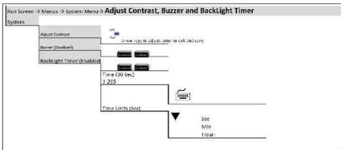
![Run Screen → Menu → System Menu → Communication System Communication Channel (Not Available) DecP (Used) Address (282 168 135.200) Subset Mask (251 215 255.0) Subway (232 168 165.4) Port (1000) 2-8899 DNS Address (192 168.3.1) Email Address [ ] Email Address [ ] Email Address [ ] CC/Email Address CC Network (Master) Server Size 7:31 Termination Relay (Enabled) Send Text: Email Msg (Not Available) Email Retry Delay (Not Available) [15] L-200 Time Units (Not Available) Set Min Hours Send Line Default Bound Rate 5600 14400 19200 38400 57500 115200 Force Serial Port (Disabled)](/content/2026/05/935752/images/c2448a83a5e57cc5c107e095ad2dd6e944168ee77217bdb07a4ec0c101081290.jpg)
Menu Maps

flowchart
graph TD
    A["Run Screen → Menu → System Menu → Configure Aux"] --> B["Probe Name ( )"]
    B --> C["Input Type (4/20ms)"]
    C --> D["**Temp Source"]
    D --> E["**Suffix ( )"]
    E --> F["*Min (2) -10000 to 10000"]
    F --> G["*Max (1000) -10000 to 10000"]
    G --> H["*Input Scaling Min (4) -10000 to 10000"]
    H --> I["*Input Scaling Max (20) -10000 to 10000"]
    I --> J["*Display Format (0)"]
    J --> K["*Aux anling only (not available for aux temperature or aux digital)"]
    K --> L["**Temperature availability on axs 3-6 only"]
Menu Maps

flowchart
graph TD
    A["Run Screen → Menus → System Menu → E-Aux System"] --> B["Configure E-Aux"]
    B --> C["E-Aux 1 - 8 (Disabled) (Name)"]
    C --> D["Probe Name ( )"]
    D --> E["Instrument (Slave) (31)"]
    E --> F["Device Address"]
    F --> G["Master Slave 1-31"]
    C --> H["Channel (Channel 1)"]
    H --> I["Channel"]
    I --> J["Channel 1-8"]
    C --> K["Input Type (4/20ma)"]
    K --> L["Digital 0-1v 0-5v 4/20ma Temperature"]
    C --> M["*Suffix ( )"]
    M --> N["*Min (0) -10000 to 10000"]
    N --> O["*Max (20) -10000 to 10000"]
    O --> P["*Input Scale Min (4.00) (suffix) -10000 to 10000"]
    P --> Q["*Input Scale Max (20) (suffix0 -10000 to 10000"]
    C --> R["Display Format (0)"]
    R --> S["0 0.0"]
    C --> T["*Aux analog only (not available for aux temperature or digital)"]
Menu Maps
Menu Maps

flowchart
graph TD
    A["System"] --> B["Data Logging"]
    B --> C["Data Logging (Enabled) (1 hour)"]
    C --> D["Logging Interval"]
    D --> E["Time units"]
    E --> F["3cc Min Hour"]
    F --> G["Event Logging (Enabled)"]
    G --> H["Clear Logs"]
    H --> I["Date Events Data and Events"]
    I --> J["Are You Sure ?"]
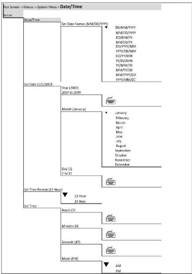
flowchart
graph TD
    A["Run Screen → Menus → System Menu → Date/Time"] --> B["System"]
    B --> C["Date/Time"]
    C --> D["Set Date Format (MM/DD/YYYY)"]
    D --> E["DD/MM/YYYY"]
    D --> F["MM/DD/YYYY"]
    D --> G["DD/MM/YY"]
    D --> H["MM/DD/YY"]
    D --> I["DD/YYYY/MM"]
    D --> J["YYYY/DD/MM"]
    D --> K["DD/YY/MM"]
    D --> L["YY/DD/MM"]
    D --> M["YY/MM/DD"]
    D --> N["MM/YY/DD"]
    D --> O["MM/YYYY/DD"]
    D --> P["YYYY/MM/DC"]
    C --> Q["Set Date (1/3/2002)"]
    Q --> R["Year (2007)"]
    R --> S["2007 to 2099"]
    S --> T["Month (January)"]
    T --> U["Day (1)"]
    U --> V["2 to 31"]
    V --> W["Set Time Format (12 Hour)"]
    W --> X["12 Hour"]
    W --> Y["24 Hour"]
    X --> Z["Set Time"]
    Y --> AA["Hours (7)"]
    AA --> AB["Minutes (0)"]
    AB --> AC["Seconds (47)"]
    AC --> AD["Mode (PM)"]
    AD --> AE["AM PM"]
Menu Maps
Menu Maps


flowchart
graph TD
    A["Run Screen → Menu → System Menu → ODO Cal K"] --> B["System"]
    B --> C["ODO Cal K"]
    C --> D["*DO-1"]
    D --> E["DO-2"]
    E --> F["DO-3"]
    F --> G["DO-4"]
    G --> H["DO-1"]
    H --> I["K1 (C0140559)"]
    H --> J["K2 (F1ECOF72)"]
    H --> K["K3 (40AA1077)"]
    H --> L["K4 (BF)8631F)"]
    H --> M["K5 (40B18767)"]
    H --> N["KC (6x4)"]
    C --> O["*5500D-1; 5500D 2; 5500D-4 only"]
    C --> P["*number of DO systems displayed is based on model number and enabled DO systems"]


flowchart
graph TD
    A["Run Screen → Menus → System Menu → General Alarm"] --> B["System"]
    B --> C["General Alarm"]
    C --> D["General Alarm (Enabled)"]
    D --> E["Alarm Hold Off (1.5 Sec) J-255"]
    E --> F["Time Units"]
    F --> G["Relay (Disabled)"]
    G --> H["General Alarm (Disabled)"]
    H --> I["Instrument (Instrument)"]
    I --> J["Relay (Relay 1) (Relay 1)"]
    J --> K["Relay 1-8"]
    K --> L["Device Address"]
    L --> M["Local Machine Master Slave 1-31"]
    M --> N["Sec Min Hours"]

flowchart
graph TD
    A["Run Screen → Menus → System Menu → Name Devices/Sensors"] --> B["System"]
    B --> C["Name Devices/Sensors"]
    C --> D["Instrument Name ( )"]
    D --> E["Aux 1-6 ( )"]
    E --> F["Name E-Aux"]
    F --> G["*DO 1-4 ( )"]
    G --> H["E-Aux 1-8"]
    H --> I["Relay 1-8"]
    I --> J["*Number of DO systems displayed is based on model number"]

flowchart
graph TD
    A["Run Screen"] --> B["Menu"]
    B --> C["System Menu"]
    C --> D["Password"]
    D --> E["Password (Disabled)"]
    E --> F["Set Password"]
Menu Maps
Menu Maps


flowchart
graph TD
    A["Run Screen → Menu → System Menu → Service"] --> B["Service"]
    B --> C["Reset Clean Probes"]
    C --> D{Clean Probes (Rashed)}
    D --> E["(0 Days Left)"]
    D --> F["Duration (0 Days) 2.365"]
    D --> G["Reset Are You Sure?"]
    B --> H["Reset To Factory"]
    H --> I["Reset All Are You Sure?"]
    I --> J["Reset Scales"]
    J --> K["Reset All Systems Are You Sure?"]
    J --> L["Reset Clean Probes Are You Sure?"]
    J --> M["Reset Data Logger Are You Sure?"]
    J --> N["Reset General Alarms Are You Sure?"]
    J --> O["Reset Password Are You Sure?"]
    J --> P["Reset Relay Names Are You Sure?"]
    J --> Q["Reset Service Are You Sure?"]
    H --> R["Reset Servers"]
    R --> S["Reset All Servers Are You Sure?"]
    R --> T["Reset Aux 1-6 Are You Sure?"]
    R --> U["Reset C-Max 1-8 Are You Sure?"]
    R --> V["Reset D0 1-9 Are You Sure?"]
    H --> W["Reset Timers"]
    W --> X["Reset All Timers Are You Sure?"]
    W --> Y["Reset Temp 1 -4 Are You Sure?"]
    W --> Z["Reset Feed Timer 1 Are You Sure?"]
    H --> AA["Output Test"]
    AA --> AB["Instrument (Instrument)"]
    AB --> AC["Device Address ▼ Local Machine Master Slave 1-31"]
    AA --> AD["Channel ▼ Channel 1-8"]
    AA --> AE["Type ▼ Relay OutPut 4/20mA ▼ Relay Energized Yes/No ▼ Output 4/20ms Millamps (0.0mA)"]
    AB --> AF["Send Request"]
Menu Maps

flowchart
graph TD
    A["Run Screen → Menu → Sensor Setup/Aux 1-8 & L-Aux 1-9 Digital Sensor Setup"] --> B["Aux ≤ 6 [Name/Disabled"] (Digital & Aux 1-8 /Name] (Disabled) (Digits)]
    B --> C["Prime (Disabled)"]
    C --> D["Control/Alarm On (Closed)"]
    D --> E["ABMn (Disabled)"]
    E --> F["Input: TIF [15% Sqrt"] L-PSS]
    F --> G["Sensor"]
    G --> H["Time Units (Sec)"]
    H --> I["Set Min Hours"]
    I --> J["Control/Alarm/Remote/Remote/Remote"]
    J --> K["Digital (Disabled)"]
    K --> L["Instrument (Instrument)"]
    L --> M["Device Address"]
    M --> N["Local Machine Member Since 1-11"]
    N --> O["Output 4/200mA (Disabled)"]
    O --> P["Temperture (Disabled) Instrument Channel Min [0.0"] Max["100.0"] Output Scale (4.0 um) Output_Scale_Max["20.00 um"]]
    P --> Q["Reay 1-8"]
    Q --> R["all menu must be configured using ActualManager"]
Menu Maps

flowchart
graph TD
    A["Run Screen → Menus → Sensor Setup"] --> B["Aux and E-Aux Analog"]
    B --> C["Sensor Setup"]
    C --> D["Probe (Standard)"]
    D --> E["Control Mode"]
    E --> F["Alarm (Standard)"]
    F --> G["Read On ILS Sec. 1-255"]
    G --> H["Time Units [Sec."]]
    H --> I["Alarm Low (90 dBm)"]
    I --> J["Relay (Standard)"]
    J --> K["Alarm Low (Disabilities)"]
    K --> L["Instrument (Instrument)"]
    L --> M["Device Address"]
    M --> N["Local Machine Master Since 1-31"]
    N --> O["Delay Unchanged"]
    O --> P["Delay 1-3"]
    P --> Q["Range Low (250) Alarm (Standard)"]
    Q --> R["Range Low (Standard)"]
    R --> S["Instrument (Instrument)"]
    S --> T["External Audio"]
    T --> U["Local Machine Master Since 1-31"]
    U --> V["Delay Unchanged"]
    V --> W["Delay 1-3"]
    W --> X["Dose Up (30 Seconds)"]
    X --> Y["Load"]
    Y --> Z["Set Min Hours"]
    Z --> AA["Delay"]
    AA --> AB["Set Point (50)"]
    AB --> AC["Control Up/Down (Rising)"]
    AC --> AD["Stop"]
    AD --> AE["Tailing"]
    AE --> AF["continued next page"]
Menu Maps

flowchart
graph TD
    A["Input to Aux/Extronicity"] --> B["PID Input (100.50)"]
    B --> C["PID Desert Interval [20.00"]]
    C --> D["PID Gain [2.00"]]
    D --> E["PID Value (Extract)"]
    E --> F["Max: 1 (Max) / Max (Max)"]
    F --> G["Output Speed (4.0ms)"]
    G --> H["Max: 1 (Max) / Max (Max)"]
    H --> I["Output Scale (3.0ms)"]
    I --> J["Max: 1 (Max) / Max (Max)"]
    J --> K["Output Scale (2.0ms)"]
    K --> L["Max: 1 (Max) / Max (Max)"]
    L --> M["Output Scale (1.0ms)"]
    M --> N["Max: 1 (Max) / Max (Max)"]
    N --> O["Output Scale (0.5ms)"]
    O --> P["Max: 1 (Max) / Max (Max)"]
    P --> Q["Output Scale (0.2ms)"]
    Q --> R["Max: 1 (Max) / Max (Max)"]
    R --> S["Output Scale (0.1ms)"]
    S --> T["Max: 1 (Max) / Max (Max)"]
    T --> U["Output Scale (0.05ms)"]
    U --> V["Max: 1 (Max) / Max (Max)"]
    V --> W["Output Scale (0.02ms)"]
    W --> X["Max: 1 (Max) / Max (Max)"]
    X --> Y["Output Scale (0.01ms)"]
    Y --> Z["Max: 1 (Max) / Max (Max)"]
    Z --> AA["Output Scale (0.005ms)"]
    AA --> AB["Max: 1 (Max) / Max (Max)"]
    AB --> AC["Output Scale (0.002ms)"]
YSI 5X00 240
Menu Maps

flowchart
graph TD
    A["Run Screen → Menu → Sensor Setup=Max[3.6"]and E.Aux["1.8"]] --> B["Temperature (all control modes unless indicated at column 2)"]
    B --> C["Sensor Setup"]
    C --> D["Temperature (hours)"]
    D --> E["Control State"]
    E --> F["Set Point: RD_PWM, RD_470mA"]
    F --> G["Display current status"]
    G --> H["Chiller On (10 MHz) 2.25"]
    H --> I["Local Control Status"]
    I --> J["Time Units"]
    J --> K["Set Min Hours"]
    K --> L["Chiller On/Off/Max 2.25"]
    L --> M["Time Units"]
    M --> N["Set Min Hours"]
    N --> O["Alarm box (23.5c) 1.1 to 44.0c*"]
    O --> P["Delay (3 seconds)"]
    P --> Q["Alarm box (3 seconds)"]
    Q --> R["Instrument (Instrument) Device 44.0c"]
    R --> S["Delay (1000 gm)"]
    S --> T["Delay 2.8"]
    T --> U["Local Machine Master Since 2.81"]
    U --> V["Delay (1000 gm)"]
    V --> W["Delay 2.8"]
    W --> X["Delay (1000 gm)"]
    X --> Y["Delay 2.8"]
    Y --> Z["Delay (1000 gm)"]
    Z --> AA["Delay 2.8"]
    AA --> AB["Delay (1000 gm)"]
    AB --> AC["Delay 2.8"]
    AC --> AD["Delay (1000 gm)"]
    AD --> AE["Delay 2.8"]
    AE --> AF["Delay (1000 gm)"]
    AF --> AG["Delay 2.8"]
    AG --> AH["Delay (1000 gm)"]
    AH --> AI["Delay 2.8"]
    AI --> AJ["Delay (1000 gm)"]
    AJ --> AK["Delay 2.8"]
    AK --> AL["Delay (1000 gm)"]
    AL --> AM["Delay 2.8"]
    AM --> AN["Delay (1000 gm)"]
    AN --> AO["Delay 2.8"]
    AO --> AP["Delay (1000 gm)"]
    AP --> AQ["Delay 2.8"]
    AQ --> AR["Delay (1000 gm)"]
    AR --> AS["Delay 2.8"]
    AS --> AT["Delay (1000 gm)"]
    AT --> AU["Delay 2.8"]
    AU --> AV["Delay (1000 gm)"]
    AV --> AW["Delay 2.8"]
    AW --> AX["Delay (1000 gm)"]
    AX --> AY["Delay 2.8"]
    AY --> AZ["Delay (1000 gm)"]
    AZ --> BA["Delay 2.8"]
    BA --> BB["Delay (1000 gm)"]
    BB --> BC["Delay 2.8"]
    BC --> BD["Delay (1000 gm)"]
    BD --> BE["Delay 2.8"]
    BE --> BF["Delay (1000 gm)"]
    BF --> BG["Delay 2.8"]
    BG --> BH["Delay (1000 gm)"]
    BH --> BI["Delay 2.8"]
    BI --> BJ["Delay (1000 gm)"]
    BJ --> BK["Delay 2.8"]
    BK --> BL["Delay (1000 gm)"]
    BL --> BM["Delay 2.8"]
    BM --> BN["Delay (1000 gm)"]
    BN --> BO["Delay 2.8"]
    BO --> BP["Delay (1000 gm)"]
    BP --> BQ["Delay 2.8"]
    BQ --> BR["Delay (1000 gm)"]
    BR --> BS["Delay 2.8"]
    BS --> BT["Delay (1000 gm)"]
    BT --> BU["Delay 2.8"]
    BU --> BV["Delay (1000 gm)"]
    BV --> BW["Delay 2.8"]
YSI 5X00 241
Menu Maps
Menu Maps

flowchart
graph TD
    A["420Hz / 420Hz drive"] --> B["P10 Gain (2.0)"]
    C["Pressure"] --> D["P10 Delay (3.6x10^6 m/s)"]
    D --> E["Temperature Standard"]
    E --> F["Instrument (instrument)"]
    F --> G["Bacha-Azzrava"]
    G --> H["Local Machine Mouse Max 1.51"]
    H --> I["Output Scale Max (20.00 m/s)"]
    J["420Hz/3Hz drive"] --> K["P10 Output 420Hz (3 scaled)"]
    K --> L["Temperature (packets), Instrument, Outlet Max 2.51"]
    L --> M["Local Machine Mouse Max 1.51"]
    M --> N["Output Scale Max (20.00 m/s)"]
    O["Range High (25 Hz) 2.8 x 440 Hz"] --> P["Beta (packets)"]
    P --> Q["Barge High (packets), Instrument (instrument)"]
    Q --> R["Bacha-Azzrava"]
    R --> S["Local Machine Mouse Max 1.51"]
    S --> T["Output Scale Max (20.00 m/s)"]
    U["Input High (25 Hz) 2.8 x 440 Hz"] --> V["Beta (packets)"]
    V --> W["Barge High (packets), Instrument (instrument)"]
    W --> X["Bacha-Azzrava"]
    X --> Y["Local Machine Mouse Max 1.51"]
    Y --> Z["Output Scale Max (20.00 m/s)"]
    AA["Output 420Hz (packets)"] --> AB["Beta (packets)"]
    AB --> AC["Barge High (packets), Instrument (instrument)"]
    AC --> AD["Bacha-Azzrava"]
    AD --> AE["Local Machine Mouse Max 1.51"]
    AE --> AF["Output Scale Max (20.00 m/s)"]
    AG["Output Scale Max (20.00 m/s)"] --> AH["Beta (packets)"]
    AH --> AI["Barge High (packets), Instrument (instrument)"]
    AI --> AJ["Bacha-Azzrava"]
    AJ --> AK["Local Machine Mouse Max 1.51"]
    AK --> AL["Output Scale Max (20.00 m/s)"]
    AM["Temperature (packets), Instrument, Outlet Max 2.51"] --> AN["Local Machine Mouse Max 1.51"]
    AN --> AO["Output Scale Max (20.00 m/s)"]
    AP["Current speed: 0.8Vrms"] --> AQ["Bottle Speed Max (AC/DC/2.5kA)"]
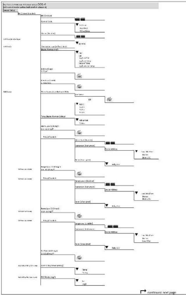
flowchart
graph TD
    A["Initial Review"] --> B{Control Study}
    B -->|Yes| C["Patient Management"]
    B -->|No| D["Patient Management"]
    C --> E{Decision?}
    E -->|Yes| F["Patient Management"]
    E -->|No| G["Patient Management"]
    F --> H{Decision?}
    H -->|Yes| I["Patient Management"]
    H -->|No| J["Patient Management"]
    I --> K{Decision?}
    K -->|Yes| L["Patient Management"]
    K -->|No| M["Patient Management"]
    L --> N{Decision?}
    N -->|Yes| O["Patient Management"]
    N -->|No| P["Patient Management"]
    O --> Q{Decision?}
    Q -->|Yes| R["Patient Management"]
    Q -->|No| S["Patient Management"]
    R --> T{Decision?}
    T -->|Yes| U["Patient Management"]
    T -->|No| V["Patient Management"]
    U --> W{Decision?}
    W -->|Yes| X["Patient Management"]
    W -->|No| Y["Patient Management"]
    X --> Z{Decision?}
    Z -->|Yes| AA["Patient Management"]
    Z -->|No| AB["Patient Management"]
    AA --> AC{Decision?}
    AC -->|Yes| AD["Patient Management"]
    AC -->|No| AE["Patient Management"]
    AD --> AF{Decision?}
    AF -->|Yes| AG["Patient Management"]
    AF -->|No| AH["Patient Management"]
    AG --> AI{Decision?}
    AI -->|Yes| AJ["Patient Management"]
    AI -->|No| AK["Patient Management"]
    AJ --> AL{Decision?}
    AL -->|Yes| AM["Patient Management"]
    AL -->|No| AN["Patient Management"]
    AM --> AO{Decision?}
    AO -->|Yes| AP["Patient Management"]
    AO -->|No| AQ["Patient Management"]
    AP --> AR{Decision?}
    AR -->|Yes| AS["Patient Management"]
    AR -->|No| AT["Patient Management"]
    AS --> AU{Decision?}
    AU -->|Yes| AV["Patient Management"]
    AU -->|No| AW["Patient Management"]
    AV --> AX{Decision?}
    AX -->|Yes| AY["Patient Management"]
    AX -->|No| AZ["Patient Management"]
    AY --> BA{Decision?}
    BA -->|Yes| BB["Patient Management"]
    BA -->|No| BC["Patient Management"]
    BB --> BD{Decision?}
    BD -->|Yes| BE["Patient Management"]
    BD -->|No| BF["Patient Management"]
    BE --> BG{Decision?}
    BG -->|Yes| BH["Patient Management"]
    BG -->|No| BI["Patient Management"]
Menu Maps
Menu Maps
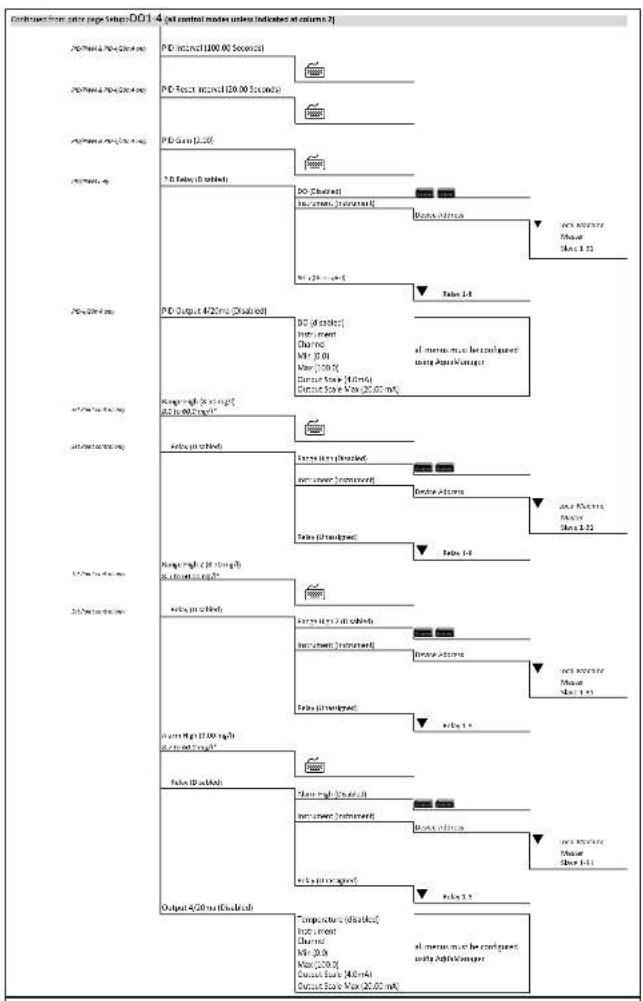
flowchart
graph TD
    A["PC-Input & PC-Output (20.00 sec)"] --> B["PD-Input (100.00 seconds)"]
    B --> C["PC-Input (20.00 seconds)"]
    C --> D["PC-Input (2.00 sec)"]
    D --> E["PC-Output (4/25 sec) (Disabled)"]
    E --> F["PC-Output (4/25 sec) (Disabled)"]
    F --> G["PC-Output (4/25 sec) (Disabled)"]
    G --> H["PC-Output (4/25 sec) (Disabled)"]
    H --> I["PC-Output (4/25 sec) (Disabled)"]
    I --> J["PC-Output (4/25 sec) (Disabled)"]
    J --> K["PC-Output (4/25 sec) (Disabled)"]
    K --> L["PC-Output (4/25 sec) (Disabled)"]
    L --> M["PC-Output (4/25 sec) (Disabled)"]
    M --> N["PC-Output (4/25 sec) (Disabled)"]
    N --> O["PC-Output (4/25 sec) (Disabled)"]
    O --> P["PC-Output (4/25 sec) (Disabled)"]
    P --> Q["PC-Output (4/25 sec) (Disabled)"]
    Q --> R["PC-Output (4/25 sec) (Disabled)"]
    R --> S["PC-Output (4/25 sec) (Disabled)"]
    S --> T["PC-Output (4/25 sec) (Disabled)"]
    T --> U["PC-Output (4/25 sec) (Disabled)"]
    U --> V["PC-Output (4/25 sec) (Disabled)"]
    V --> W["PC-Output (4/25 sec) (Disabled)"]
    W --> X["PC-Output (4/25 sec) (Disabled)"]
    X --> Y["PC-Output (4/25 sec) (Disabled)"]
    Y --> Z["PC-Output (4/25 sec) (Disabled)"]
    Z --> AA["PC-Output (4/25 sec) (Disabled)"]
    AA --> AB["PC-Output (4/25 sec) (Disabled)"]
    AB --> AC["PC-Output (4/25 sec) (Disabled)"]
    AC --> AD["PC-Output (4/25 sec) (Disabled)"]
    AD --> AE["PC-Output (4/25 sec) (Disabled)"]
    AE --> AF["PC-Output (4/25 sec) (Disabled)"]
    AF --> AG["PC-Output (4/25 sec) (Disabled)"]
    AG --> AH["PC-Output (4/25 sec) (Disabled)"]
    AH --> AI["PC-Output (4/25 sec) (Disabled)"]
    AI --> AJ["PC-Output (4/25 sec) (Disabled)"]
    AJ --> AK["PC-Output (4/25 sec) (Disabled)"]
    AK --> AL["PC-Output (4/25 sec) (Disabled)"]
    AL --> AM["PC-Output (4/25 sec) (Disabled)"]
    AM --> AN["PC-Output (4/25 sec) (Disabled)"]
    AN --> AO["PC-Output (4/25 sec) (Disabled)"]
    AO --> AP["PC-Output (4/25 sec) (Disabled)"]
    AP --> AQ["PC-Output (4/25 sec) (Disabled)"]
    AQ --> AR["PC-Output (4/25 sec) (Disabled)"]
    AR --> AS["PC-Output (4/25 sec) (Disabled)"]
    AS --> AT["PC-Output (4/25 sec) (Disabled)"]
    AT --> AU["PC-Output (4/25 sec) (Disabled)"]
    AU --> AV["PC-Output (4/25 sec) (Disabled)"]
    AV --> AW["PC-Output (4/25 sec) (Disabled)"]
    AW --> AX["PC-Output (4/25 sec) (Disabled)"]
    AX --> AY["PC-Output (4/25 sec) (Disabled)"]
    AY --> AZ["PC-Output (4/25 sec) (Disabled)"]
    AZ --> BA["PC-Output (4/25 sec) (Disabled)"]
    BA --> BB["PC-Output (4/25 sec) (Disabled)"]
    BB --> BC["PC-Output (4/25 sec) (Disabled)"]
    BC --> BD["PC-Output (4/25 sec) (Disabled)"]
    BD --> BE["PC-Output (4/25 sec) (Disabled)"]
    BE --> BF["PC-Output (4/25 sec) (Disabled)"]
    BF --> BG["PC-Output (4/25 sec) (Disabled)"]
    BG --> BH["PC-Output (4/25 sec) (Disabled)"]
    BH --> BI["PC-Output (4/25 sec) (Disabled)"]
    BI --> BJ["PC-Output (4/25 sec) (Disabled)"]
    BJ --> BK["PC-Output (4/25 sec) (Disabled)"]
    BK --> BL["PC-Output (4/25 sec) (Disabled)"]
    BL --> BM["PC-Output (4/25 sec) (Disabled)"]
    BM --> BN["PC-Output (4/25 sec) (Disabled)"]
    BN --> BO["PC-Output (4/25 sec) (Disabled)"]
    BO --> BP["PC-Output (4/25 sec) (Disabled)"]
    BP --> BQ["PC-Output (4/25 sec) (Disabled)"]
    BQ --> BR["PC-Output (4/25 sec) (Disabled)"]
    BR --> BS["PC-Output (4/25 sec) (Disabled)"]
    BS --> BT["PC-Output (4/25 sec) (Disabled)"]
    BT --> BU["PC-Output (4/25 sec) (Disabled)"]
    BU --> BV["PC-Output (4/25 sec) (Disabled)"]
    BV --> BW["PC-Output (4/25 sec) (Disabled)"]
    BW --> BX["PC-Output (4/25 sec) (Disabled)"]
    BX --> BY["PC-Output (4/25 sec) (Disabled)"]
    BY --> BZ["PC-Output (4/25 sec) (Disabled)"]
    BZ --> CA["PC-Output (4/25 sec) (Disabled)"]
    CA --> CB["PC-Output (4/25 sec) (Disabled)"]
    CB --> CC["PC-Output (4/25 sec) (Disabled)"]
    CC --> CD["PC-Output (4/25 sec) (Disabled)"]
    CD --> CE["PC-Output (4/25 sec) (Disabled)"]
    BE --> CF["PC-Output (4/25 sec) - DisTable"]
    CF --> CG["PC-Output (4/25 sec) - DisTable"]
YSI 5X00
244

flowchart
graph TD
    A["Run Screen → Manus → Timers → Timers 1-4"] --> B["Timer 1-4 Disabled"]
    B --> C["Relay (Dis Jordan)"]
    C --> D["Instrument (instrument)"]
    D --> E["Device Address"]
    E --> F["Local Machine Master Slave 1-31"]
    D --> G["Relay (Unassigned)"]
    G --> H["Relay 1-8"]
    H --> I["Start Time (12:00:00 AM)"]
    I --> J["Hours (12)<br>1-12<br>Minutes (0)<br>0-59<br>Seconds (0)<br>0-59"]
    J --> K["Mode"]
    K --> L["AM<br>PM"]
    I --> M["Duration (6 Sec)<br>1-2ET"]
    M --> N["Time Units"]
    N --> O["Sec<br>Min<br>Hours"]
YSI 5X00
245
Menu Maps
Menu Maps

flowchart
graph TD
    A["Feed Time (Disked)"] --> B["FCR (Disked)"]
    B --> C{Feed Mode}
    C -->|Yes| D["Feed Size (KΩ)"]
    C -->|No| E["Load Loading (J) - 1.75"]
    D --> F["Start Date (30/01/2007)"]
    F --> G{Start Time (12:00:00 AM)}
    G -->|Yes| H["End Date (30/01/2007)"]
    G -->|No| I["End Date (30/01/2007)"]
    I --> J["End Time (12:00:00 AM)"]
    J --> K["End Time (12:00:00 AM)"]
    K --> L["End Time (12:00:00 AM)"]
    L --> M["End Time (12:00:00 AM)"]
    M --> N["End Time (12:00:00 AM)"]
    N --> O["End Time (12:00:00 AM)"]
    O --> P["End Time (12:00:00 AM)"]
    P --> Q["End Time (12:00:00 AM)"]
    Q --> R["End Time (12:00:00 AM)"]
    R --> S["End Time (12:00:00 AM)"]
    S --> T["End Time (12:00:00 AM)"]
    T --> U["End Time (12:00:00 AM)"]
    U --> V["End Time (12:00:00 AM)"]
    V --> W["End Time (12:00:00 AM)"]
    W --> X["End Time (12:00:00 AM)"]
    X --> Y["End Time (12:00:00 AM)"]
    Y --> Z["End Time (12:00:00 AM)"]
    Z --> AA["End Time (12:00:00 AM)"]
    AA --> AB["End Time (12:00:00 AM)"]
    AB --> AC["End Time (12:00:00 AM)"]
    AC --> AD["End Time (12:00:00 AM)"]
    AD --> AE["End Time (12:00:00 AM)"]
    AE --> AF["End Time (12:00:00 AM)"]
    AF --> AG["End Time (12:00:00 AM)"]
    AG --> AH["End Time (12:00:00 AM)"]
    AH --> AI["End Time (12:00:00 AM)"]
    AI --> AJ["End Time (12:00:00 AM)"]
    AJ --> AK["End Time (12:00:00 AM)"]
    AK --> AL["End Time (12:00:00 AM)"]
    AL --> AM["End Time (12:00:00 AM)"]
    AM --> AN["End Time (12:00:00 AM)"]
    AN --> AO["End Time (12:00:00 AM)"]
    AO --> AP["End Time (12:00:00 AM)"]
    AP --> AQ["End Time (12:00:00 AM)"]
    AQ --> AR["End Time (12:00:00 AM)"]
    AR --> AS["End Time (12:00:00 AM)"]
    AS --> AT["End Time (12:00:00 AM)"]
    AT --> AU["End Time (12:00:00 AM)"]
    AU --> AV["End Time (12:00:00 AM)"]
    AV --> AW["End Time (12:00:00 AM)"]
    AW --> AX["End Time (12:00:00 AM)"]
    AX --> AY["End Time (12:00:00 AM)"]
    AY --> AZ["End Time (12:00:00 AM)"]
    AZ --> BA["End Time (12:00:00 AM)"]
    BA --> BB[End Time (12: 31)
End Time (12:31)
End Time (12:31)
End Time (12:31)
End Time (12:31)
End Time (12:31)
End Time (12:31)
End Time (12:31)
End Time (12:31)
End Time (12:31)
End Time (12:31)
End Time (12:31)
End Time (12:46)
End Time (12:46)
End Time (12:46)
End Time (12:46)
End Time (12:46)
End Time (12:46)
End Time (12:46)
End Time (12:46)
End Time (12:46)
End Time (12:46)
End Time (12:46)
End Time (12:46
End Time (12:46)
End Time (12:46)
End Time (12:46)
End Time (12:46)
End Time (12:46)
End Time (12:46)
End Time (12:46)
End Time (12:46)
End Time (12:46)
End Time (12:46)
End Time (12:46)
end

flowchart
graph TD
    A["ReadSmart Timer 1-4"] --> B["Last Time (12:00): 64 AM"]
    B --> C["Hours (127)<br>L-12"]
    C --> D["Minutes (0)<br>L-59"]
    D --> E["Seconds (5)<br>L-19"]
    E --> F["State (4V)"]
    F --> G["AM<br>PM"]
    G --> H["Sum Sat (Cloudtch)"]
    H --> I["Sensor(Download)"]
    I --> J["Scan time (0.00 mph)<br>Stop 60.50"]
    J --> K["30/140 (1.00 mg,ft)<br>Stop 60.50"]
    K --> L["DO Change (0.0%,5)<br>0-20 to 8.5%<br>Timing Time (8.5c)<br>2 to 64.0c"]
    L --> M["Temp Rate (0.0%,5)<br>12p to 84.0c"]
    M --> N["Long Change (0.0%,5)<br>USD to 6.5m"]
    N --> O["Delay (Download)"]
    O --> P["End Smart Timer (Download)"]
    P --> Qinstrument(Instrument)
    Q --> R["Device Audio"]
    R --> S["Local Machine<br>Marker<br>Starts 5-31"]
    S --> T["Index (Unread prompt)<br>Reay 1-8"]
    T --> U["Units [wt"]]
    U --> V["us<br>us<br>us"]
    V --> W["Cable site (1882) (6 wt)"]
    W --> X["End Timer Test Run Time<br>end Timer Test Weight"]

Appendix 4 - Declaration of Conformity
The undersigned hereby declares on behalf of the named manufacturer under our sole responsibility that the listed product conforms to the requirements for the listed European Council Directive(s) and carries the CE mark accordingly.
| Manufacturer: YSI Incorporated | |
| 1725 Brannum LaneYellow Springs, OH 45387USA | |
| Product Name: 5400, 5500D | -01, 5500D-02, 5500D-04 |
| Model Numbers | |
| Instrument/Accessory: 5400 | 5500D-01, 5500D-02, 5500D-04 |
| Conforms to the following: | |
| Directives: EMC 2004/108/ | ECRoHS 2011/65/EUWEEE 2002/96/ECLVD 2006/95/EC |
| Harmonized Standards: • EN | EN61326-1:2006, Electrical equipment for measurement, control, and laboratory use - EMC requirements - Part 1: General Requirements• EN61326-2-3:2006, Electrical equipment for measurement, control and laboratory use - EMC requirements - Part 2-3: Particular Requirements - Test configuration, operational conditions, and performance criteria for transducers with integrated or remote signal conditioning.• EN61000-3-2:2006+A1:2009+A2:2009, Electromagnetic compatibility (EMC) - Part 3-2: Limits - Limits for harmonic current emissions (equipment input current < 16A per phase).• EN61000-3-3:2008, Electromagnetic compatibility (EMC) - Part 3-3: Limits - Limitation of voltage changes, voltage fluctuations and flicker in public low-voltage supply systems, for equipment with rated current < 16A per phase and not subject to conditional connection..• IEC61010-1:2010 |
| Supplementary Information: | All performance met the continuous unmonitored operation criteria as follows:• ESD, EN61000-4-2:2008 2nd edition• Radiated Immunity, EN61000-4-3:2006+A1:2007 3rd edition.•EFT, EN61000-4-4:2004 2nd edition, (EFT).• Surge, EN61000-4-5:2005 2nd edition• Conducted Immunity, EN61000-4-6:2008 3rd edition• Voltage Interrupts, EN61000-4-11:2004 2nd edition• EN61000-4-8:2001 1st edition Power frequency magnetic field immunity |
| Authorized EU Representative | YSI Hydrodata LtdUnit 8, Business Centre West, Avenue 1 Letchworth, Hertfordshire, SG6 2HB UK |
Tusc Mail
Signed: Lisa M. Abel
Date: 24 July 2011
Title: Director of Quality
The undersigned hereby declares on behalf of the named manufacturer under our sole responsibility that the listed product conforms to the requirements for electrical equipment under US FCC Part 15 and ICES-003 for unintentional radiators.
| Manufacturer: YSI Incorporated | |
| 1725 Brannum LaneYellow Springs, OH 45387USA | |
| Product Name: 5400, 5500D-01, 5500D-02, 5500D-04 | |
| Model Numbers | |
| Instrument/Accessory: 5400, 5500D-01, 5500D-02, 5500D-04 | |
| Conforms to the following: | |
| Standards: | FCC 47 CFR Part 15-2008, Radio Frequency DevicesICES-003:2004, Digital Apparatus |
| Supplementary Information: | Tested using ANSI C63.4-2003 and CAN/CSA-CEI/IEC CISPR 22:02 |
Tuo Mail
Signed: Lisa M. Abel
Date: 24 July 2011
Title: Director of Quality
The undersigned hereby declares on behalf of the named manufacturer under our sole responsibility that the listed product conforms with the Australian and New Zealand Electromagnetic Compatibility (EMC) requirements for generic products to be used in residential, commercial, and light industrial environments.
| Manufacturer: YSI Incorporated | 1725 Brannum LaneYellow Springs, OH 45387USA |
| Product Name: 5400, 5500D-0 | , 5500D-02, 5500D-04 |
| Model Numbers | |
| Instrument/Accessory: 5400, 5500D-01, 5500D-02, 5500D-04 | |
| Conforms to the following: | |
| Standards: • AS/NZS 61000.6. | :2007+A1:2009 Electromagnetic compatibility (EMC), Part 6-3-Emission• AS/NZC 61000.3.2:2007+A1:2009 EMC, Limits for harmonic current emissions• AS/NZS 61000.3.3:2006, Limitation of voltage changes, voltage fluctuations and flicker in public low-voltage supply systems• AS/NZC 61000.6.1:2006 EMC Part 6-1. Immunity. |
Tino Mail
Signed: Lisa M. Abel
Date: 24 July 2011
Title: Director of Quality
FCC Required Notice
The Federal Communications Commission defines this product as a computing device and requires the following notice.
This equipment generates and uses radio frequency energy and if not installed and used properly, may cause interference to radio and television reception. It has been type tested and found to comply with the limits for a Class A or Class B computing device in accordance with the specification in Subpart J of Part 15 of FCC Rules, which are designed to provide reasonable protection against such interference in a residential installation. However, there is no guarantee that interference will not occur in a particular installation. If this equipment does cause interference to radio or television reception, which can be determined by turning the equipment off and on, the user is encouraged to try to correct the interference by one or more of the following measures:
- Reorient the receiving antenna
- Relocate the computer with respect to the receiver
- Move the computer away from the receiver
- Plug the computer into a different outlet so that the computer and receiver are on different branch circuits.
If necessary, the user should consult the dealer or an experienced radio/television technician for additional suggestions. The user may find the following booklet, prepared by the Federal Communications Commission, helpful: "How to Identify and Resolve Radio-TV Interference Problems". This booklet is available from the U.S. Government Printing Office, Washington, D.C. 20402, Stock No.0004-000-00345-4.
Appendix 5 Parts and Accessories
| Replacement Part Part Number and D | Description |
| Galvanic probe/cable assembliescable lengths available: 4m, 10m, 20m, 30m, and custom to 100 m | |
| p/n 5420-X (X=cable length; galvanic DO probe cable assembly)p/n 5421-X (X=cable length; galvanic and temperature probe cable assembly) | |
| DO Membranes for Galvanic DO Sensor | |
| 2 mil Teflon 5405-5 membrane kit contains: | -5 membrane-electrolyte solution |
| 2 mil Teflon 5405-25 membrane kit contains: | -25 membranes-electrolyte solution |
| Electrolyte solution 5406, 1 pint | |
| DO Membranes and electrolyte solution for Polarographic sensor | |
| 2 mil PE (blue) 605307 membrane kit contains: | -6 cap membranes-electrolyte solution-sanding disk-3 gaskets |
| 2 mil Teflon (gray) 605204 membrane kit contains: | -6 cap membranes-Probe electrolyte-sanding disk-3 gaskets |
| ODO probe/cable assemblies and replacement sensor capcable lengths available: 1m, 4m, 10m, 20m, 30m, and custom to 100 m | |
| 626250-X (X=cable length; ODO probe cable assembly) | |
| 626320 Replacement Sensor Cap | |
| Installation Mounting kits | |
| Panel mount kit 006510 - for mounting | 5200A instrument to a panel. |
| Rail mount kit 006509 - for mounting a | 5200A instrument to a rail. |
| Weather shield kit 006505 | |
| Replacement Part Part Number and Description | |
| Other | |
| AC Power cord, 115 VAC, USA plug 60 | 5880, for AC version only, included with AC version |
| Adapter, DB-9 to RJ-45 655383, included with instrument | |
| AquaManager Software, single and network use | 655363 |
| Compression Plugs, Large 605230, 2 each included with instrument | |
| Compression Plugs, Large 605229, 2 each included with instrument | |
| Compression Plugs, Medium 605898, 3 each included with instrument | |
| Compression Plugs, Small 605804, 4 each included with instrument | |
| Conduit fittings | 065926UL. - For optional conduit mount, industrial encapsulant required |
| Conduit Sealer | 065921, industrial encapsulant require for above item |
| Desiccant pack replacement | 006506, included with instrument |
| DO (Galvanic) sensor reconditioning kit | 5407 |
| Dual Male, RJ-45 Cable Assembly | 655384, included with instrument |
| Flange Mounting Kit | 006515, included with instrument |
| Grounding Screws | 605889, included with instrument |
| Pluggable Socket Connector for AC power, 3 pole | 605944UL, for AC version only, included with AC version |
| Pluggable Socket Connector for Auxiliary Inputs, 3 pole | 605940UL, included with instrument |
| Pluggable Socket Connector for Aux and DO inputs, 8 pole | 605942UL, included with instrument |
| Pluggable Socket Connector for relays, 12 pole | 605943UL, 2 each included with instrument |
| Pluggable Socket Connector for RS-485, 5 pole | 605941UL, included with instrument |
| Pluggable Socket Connector for 12 VDC power, 2 pole | 506939UL, included with instrument |
| RS-232 Opto Isolator, DB-9 to RJ-45 | 605285 |
| Serial to Ethernet device kit | 5402 |
| User Manual | 605878, included with instrument |
| 12-volt power supply, 115 VAC input 6 | 05227UL |
| 12-volt power supply, 230 VAC input 6 | 55478UL |
| 230 VAC power cord, European (AC version only) | 606100 |
| 230 VAC power cord, UK (AC version only) | 606101 |
| 230 VAC power cord, Australia (AC version only) | 606102 |
| USB to Serial PC adapter YSI part number #773 | |
Appendix 6 - SMS messaging
SMS (Short Message Service) or text messaging is a service for sending messages to your Cell phone or Pager (mobile device). Using the optional xPort Ethernet solution, you can redirect your alarm messages to your mobile device.
Under the Service->Communications->Ethernet menu you will find a menu item called Email Address. Using the format from your carrier, see list below, replace your email address with this information. Example: Your Cell phone number is 858-555-1212 and your carrier is Sprint PCS, your email address would be 8585551212@messaging.sprintpcs.com. Note the maximum size of your email address or cell phone information is 49 characters. This should be large enough to cover most email addresses.
Below is a list of major USA Cellular and Pager companies that support sending Text messages to a Cell Phone or pager device via email (xPort Ethernet solution). If your carrier is international or is not listed here, please visit http://www.notepage.net/smtp.htm for a more comprehensive list or contact your service provider for information on how to send a SMS or Email message to your mobile device.
Company Name SMTP Format
Alltel [10-digit phone number]@message.alltel.com
AT&T [10-digit phone number]@txt.att.net
Boost [10-digit
Nextel [10-digit telephone number]@messaging.nextel.
com
Sprint PCS [10-digit phone number]@messaging.sprintpcs.
com
T-Mobile [10-digit phone number]@tmomail.net
US Cellular [10-digit phone number]@email.uscc.net (SMS)
Verizon [10-digit phone number]@vtext.com
Virgin Mobile USA [10-digit phone number]@vmobl.com
data current as of April 2, 2012 @http://www.notepage.net/smtp.htm
Appendix 7 - Alpha "A" curve
ALPHA "A" CURVE
Resistance-Temperature Conversion Table
| Temp°C | Resistance | Temp°C | Resistance | Temp°C | Resistance | Temp°C | Resistance |
| -40 | 336600.0000 | 8 | 21920.0000 | 56 | 2878.00000 | 104 | 605.000000 |
| -39 | 315000.0000 | 9 | 20880.0000 | 57 | 2774.00000 | 105 | 588.000000 |
| -38 | 295000.0000 | 10 | 19900.0000 | 58 | 2674.00000 | 106 | 571.400000 |
| -37 | 276400.0000 | 11 | 18970.0000 | 59 | 2580.00000 | 107 | 555.600000 |
| -36 | 259000.0000 | 12 | 18090.0000 | 60 | 2488.00000 | 108 | 540.200000 |
| -35 | 242800.0000 | 13 | 17260.0000 | 61 | 2400.00000 | 109 | 525.200000 |
| -34 | 227800.0000 | 14 | 16460.0000 | 62 | 2316.00000 | 110 | 510.800000 |
| -33 | 213800.0000 | 15 | 15710.0000 | 63 | 2234.00000 | 111 | 496.800000 |
| -32 | 200600.0000 | 16 | 15000.0000 | 64 | 2158.00000 | 112 | 483.200000 |
| -31 | 188400.0000 | 17 | 14320.0000 | 65 | 2082.00000 | 113 | 470.200000 |
| -30 | 177000.0000 | 18 | 13680.0000 | 66 | 2012.00000 | 114 | 457.400000 |
| -29 | 166400.0000 | 19 | 13070.0000 | 67 | 1942.00000 | 115 | 443.200000 |
| -28 | 156500.0000 | 20 | 12490.0000 | 68 | 1876.00000 | 116 | 433.400000 |
| -27 | 147200.0000 | 21 | 11940.0000 | 69 | 1813.00000 | 117 | 421.800000 |
| -26 | 138500.0000 | 22 | 11420.0000 | 70 | 1751.00000 | 118 | 410.600000 |
| -25 | 130400.0000 | 23 | 10920.0000 | 71 | 1693.00000 | 119 | 399.800000 |
| -24 | 122900.0000 | 24 | 10450.0000 | 72 | 1637.00000 | 120 | 389.400000 |
| -23 | 115800.0000 | 25 | 10080.0000 | 73 | 1582.00000 | 121 | 379.200000 |
| -22 | 109100.0000 | 26 | 9574.0000 | 74 | 1530.00000 | 122 | 369.400000 |
| -21 | 102900.0000 | 27 | 9166.0000 | 75 | 1480.00000 | 123 | 359.800000 |
| -20 | 97120.0000 | 28 | 8778.0000 | 76 | 1432.00000 | 124 | 350.600000 |
| -19 | 91660.0000 | 29 | 8408.0000 | 77 | 1385.00000 | 125 | 341.600000 |
| -18 | 86540.0000 | 30 | 8058.0000 | 78 | 1341.00000 | 126 | 332.800000 |
| -17 | 81720.0000 | 31 | 7722.0000 | 79 | 1298.00000 | 127 | 324.400000 |
| -16 | 77220.0000 | 32 | 7404.0000 | 80 | 1256.00000 | 128 | 316.200000 |
| -15 | 72980.0000 | 33 | 7098.0000 | 81 | 1216.00000 | 129 | 308.200000 |
| -14 | 69000.0000 | 34 | 6808.0000 | 82 | 1178.00000 | 130 | 300.600000 |
| -13 | 65260.0000 | 35 | 6532.0000 | 83 | 1141.00000 | 131 | 293.000000 |
| -12 | 61760.0000 | 36 | 6268.0000 | 84 | 1105.00000 | 132 | 285.800000 |
| -11 | 58460.0000 | 37 | 6016.0000 | 85 | 1071.00000 | 133 | 278.800000 |
| -10 | 55340.0000 | 38 | 5776.0000 | 86 | 1038.00000 | 134 | 272.000000 |
| -9 | 52420.0000 | 39 | 5546.0000 | 87 | 1006.00000 | 135 | 265.200000 |
| -8 | 49660.0000 | 40 | 5326.0000 | 88 | 975.00000 | 136 | 258.800000 |
| -7 | 47080.0000 | 41 | 5118.0000 | 89 | 945.20000 | 137 | 252.600000 |
| -6 | 44640.0000 | 42 | 4918.0000 | 90 | 916.40000 | 138 | 246.400000 |
| -5 | 42340.0000 | 43 | 4726.0000 | 91 | 888.80000 | 139 | 240.600000 |
| -4 | 40160.0000 | 44 | 4544.0000 | 92 | 862.00000 | 140 | 234.800000 |
| -3 | 38120.0000 | 45 | 4368.0000 | 93 | 836.40000 | 141 | 229.200000 |
| -2 | 36200.0000 | 46 | 4202.0000 | 94 | 811.40000 | 142 | 223.800000 |
| -1 | 34380.0000 | 47 | 4042.0000 | 95 | 787.40000 | 143 | 218.400000 |
| 0 | 32660.0000 | 48 | 3888.0000 | 96 | 764.20000 | 144 | 213.400000 |
| 1 | 31040.0000 | 49 | 3742.0000 | 97 | 741.80000 | 145 | 208.400000 |
| 2 | 29500.0000 | 50 | 3602.0000 | 98 | 720.20000 | 146 | 203.600000 |
| 3 | 28060.0000 | 51 | 3468.0000 | 99 | 699.40000 | 147 | 198.800000 |
| 4 | 26680.0000 | 52 | 3340.0000 | 100 | 679.20000 | 148 | 194.200000 |
| 5 | 25400.0000 | 53 | 3216.0000 | 101 | 659.60000 | 149 | 189.700000 |
| 6 | 24180.0000 | 54 | 3098.0000 | 102 | 640.80000 | 150 | 185.400000 |
| 7 | 23020.0000 | 55 | 2986.0000 | 103 | 622.60000 |
Appendix 8 - Warranty
The YSI 5X00 instrument is warranted by YSI for two years from date of purchase by the end user against defects in materials and workmanship (excluding components and materials for the YSI 5X00 which are separately warranted below). All YSI cables, probe modules, and sensors for the YSI 5X00 are warranted by YSI for one year from date of purchase by the end user against defects in material and workmanship. Within the applicable warranty period, YSI will repair or replace, at its sole discretion, free of charge, any product that YSI determines to be covered by this warranty.
To exercise this warranty, call your local YSI representative, or contact YSI customer service in Yellow Springs, Ohio at +1 937 767-7241. Send the product and proof of purchase, transportation prepaid, to the Authorized Service Center selected by YSI. Repair or replacement will be made and the product returned, transportation prepaid. Repaired or replaced products are warranted for the balance of the original warranty period, or at least 90 days from date of repair or replacement. The end user making a claim under any of these warranties is responsible for all product removal and reinstallation costs related to any product repair or replacement under any such warranty.
Limitation of Warranty
This warranty does not apply to any YSI product damage or failure caused by:
- failure to install, operate or use the product in accordance with YSI's written instructions;
- abuse or misuse of the product;
- failure to maintain the product in accordance with YSI's written instructions or standard industry procedure;
- any improper, incorrect or substandard repairs to the product not performed by YSI;
- use by anyone (other than YSI) of any defective or improper component or part in servicing or repairing the product;
- modification of the product in any way not expressly authorized by YSI.
THIS WARRANTY IS IN LIEU OF ALL OTHER WARRANTIES, EXPRESSED OR IMPLIED, INCLUDING ANY WARRANTY OF MERCHANTABILITY OR FITNESS FOR A PARTICULAR PURPOSE. YSI'S LIABILITY UNDER THIS WARRANTY IS LIMITED TO REPAIR OR REPLACEMENT OF THE PRODUCT, AND THIS SHALL BE THE SOLE AND EXCLUSIVE REMEDY FOR ANY DEFECTIVE PRODUCT COVERED BY THIS WARRANTY. IN NO EVENT SHALL YSI BE LIABLE FOR ANY SPECIAL, INDIRECT, INCIDENTAL OR CONSEQUENTIAL DAMAGES RESULTING FROM OR CAUSED BY ANY DEFECTIVE PRODUCT COVERED BY THIS WARRANTY.
Appendix 9 - Contact Us
Ordering and Technical Support
Please visit www.ysi.com for a list of YSI's locations worldwide along with additional contact information.
YSI, Inc. Corporate Headquarters:
Telephone: 800 897 4151 (US)
+1 937 767 7241 (Globally)
Monday through Friday, 8:00 AM to 5:00 ET
Fax: +1 937 767 9353 (orders)
+1 937 767 1058 (technical support)
Email: environmental@ysi.com
Mail: YSI Incorporated
1725 Brannum Lane
Yellow Springs, OH 45387 USA
Web Site: www.ysi.com
When placing an order please have the following available:
1.) YSI account number (if available)
2.) Name and phone number
3.) Purchase Order or Credit Card
4.) Model Number or brief description
5.) Billing and shipping addresses
6.) Quantity
Service Information
YSI has authorized service centers throughout the United States and Internationally. For the nearest service center information, please visit www.ysi.com and click 'Support' or contact YSI Technical Support directly at +1 937-767-7241.
When returning a product for service, include the Product Return form with cleaning certification. The form must be completely filled out for a YSI Service Center to accept the instrument for service. The form may be downloaded from www.ysi.com by clicking on the 'Support' tab, then the Product Return Form button..
Appendix 10 - Recycling
Recycling
YSI is committed to reducing the environmental footprint in the course of doing business. Even though materials reduction is the ultimate goal, we know there must be a concerted effort to responsibly deal with materials after they've served a long, productive life-cycle. YSI's recycling program ensures that old equipment is processed in an environmentally friendly way, reducing the amount of material going to landfills.
- Printed Circuit Boards are sent to facilities that process and reclaim as much material for recycling as possible.
- Plastics enter a material recycling process and are not incinerated or sent to landfills.
- Batteries are removed and sent to battery recyclers for dedicated metals.
When the time comes for you to recycle, follow the easy steps outlined at www.ysi.com.
Battery Disposal
The circuit board in this instrument contains a manganese dioxide lithium "coin cell" battery that must be in place for continuity of power to memory devices on the board. This battery is not user serviceable or replaceable. When appropriate, an authorized YSI service center will remove this battery and properly dispose of it, per service and repair policies
Index
Index
Symbols
5X00
meaning & usage 10, 12
30 second power up delay 75, 152
30 second sensor system hold off 159, 160
A
Adjust contrast menu 87
Alarms
alarm hold off 132
alarm value 156
general alarm 131
AquaManager 197
and data logging 118, 121, 204
and sensor setup menu 179
and system menu 149
and timer menu 190
autopoller 204
alarm emails 206
mapping 205
database management 204
installation 198
PC requirements 198
Windows 200
explorer window 200
node (graph) window 202
systems management 203
Autofix 157
Auxiliary (Aux) systems
configure 101
display format 105, 114
input type 103, 110, 111
analog (non temperature) 104
analog (temperature) 107
digital 103
min/max values 104, 114
Index
probe name 102
suffix 104, 113
control/alarm low and high. See sensor setup analog (aux non temperature)
control/alarm on open or closed. See sensor setup (aux) digital
input scaling 105, 114
sensor setup (non temperature)
analog (non temperature) 166
hold off 164
relay 166, 177
sensor setup (temperature) 168
wiring
analog (non temperature) 59
digital 59
temperature sensor 52
B
Backlight timer menu 89
Baud rate (RS232) 100
Biomass (feed timer) 186
Bulkhead fittings 40
rubber grommets 40
Buzzer menu 89
C
Calibration
calibration menu 81
DO mg/l 84
DO % sat 83
feed timer 189
getting ready to calibrate DO sensor 82
log 83
sensors
"check probe" 82
Chiller hold off time (temperature control high) 157
Circuit Boards. See PCBs
Clean probe timer 140
Clear Logs 121
Communication hardware wiring 66
Index
Index
Communication menu 89
email alarming 90
email retry delay 100
ethernet 92
SMS messaging 96
force serial port 101
Network 96
RS232 baud rate 100
send test email 99
Configuration log 118
configure E-Aux system menu 108
contactor. See Wiring contactor
Contact Us 258
Control board 42
Control menu 192
control modes 152, 153
Control modes
PID/PWM control mode 159, 160
PID/PWM Tuning 163
set point control mode 153
D
Daily feedings (Feed Smart timer) 185
Daily weight (Feed Smart timer fcr) 186
Daily weight (Feed Smart timer-non fcr) 185
Data Logging menu
clear logs 121
event log 120
sensor log (data log) 118
Date and Time menu 122
Declaration of conformity 248
Defaults. See Factory defaults
device time out error. See Firmware Updater
DHCP (ethernet menu) 93
Display format (analog aux non temperature) 105, 114
Display Settings menu 123
DNS address (ethernet menu) 95
DO sensor calibration mg/l 84
DO sensor calibration % sat 83
DO sensor setup 173
E
E-Aux
Offline 173
Email addresses (ethernet menu) 95
Email alarming 90
5400 email 90
AquaManager email 90
email retry delay 100
send test email 99
Ethernet menu 92
DHCP 93
DNS address 95
email addresses 95
gateway 94
IP address 93
port 95
subnet mask 94
Ethernet module
configure communications ethernet menu 92
installation 68
SMS messaging 96
Event logging 120
Event log view 194
Explorer window - AquaManager 200
F
Factory defaults 225
fcr (feed timer) 186
Feed Smart Timer
biomass 186
calibrate 189
daily feedings 185
daily weight 186
fcr
biomass 186
daily weight 186
fcr factor 187
feed % biomass 186
Index
Index
feed mode
continuous 184
timed 184
sensors 187
DO and temperature low/high % change 188
Firmware Updater
could not find unit error 130
device timed out error 130
forcedownloader 130
Unit is Up-To-Date message 130
Force serial port (communications menu) 101
Front panel
keys 73
open 41
run screen 75
softkeys 73
G
Gateway (ethernet menu) 94
General Alarm menu 131
hold off 132
relay 132
Grounding
5400 43
tanks 43
H
Hardware
bulkhead fittings 40
ethernet module 68
installation and wiring chapter 25
lower board assembly 42
PCBs 39
I
Icons 76
input scaling (aux systems) 105, 114
Input type (aux) 103, 110, 111
Installation 26–35. See also Wiring
5400 location considerations 27
Installation and wiring chapter 25
mounting 5400
panel 29
rail 29
surface 28
weather shield 33
qualified installer 12, 21
sensors
DO 5420 & 5421 galvanic 37
DO 5422 polarographic 37
location considerations 35
temperature 38
system schematic (sample) 26
instrument and relay name conventions 136
I/O Board 39
accessing 40
IOEM/REM. See IOEM/REM-see IOEM/REM safety and installation guide for wiring and configuration info
IOEM/REM installation 68
1P address (ethernet menu) 93
K
keys. See Front panel
L
Lanyard 31,40
Lightning and Surge Protection 68
local versus remote machine 86
Logs
calibration 83
clear logs 121
configuration log 118
event log 120
sensor log (data log) 118
M
Maintenance
AquaManager database maintenance 216
DC batteries 216
Index
Index
Menus
Calibration 81
DO
mg/l 84
%sat 83
Control 192
Hierarchy 78
Menu maps 225
menu map key 226
Msg's menu 193
Sensor setup 150
Aux
analog 0-1V, 0-5V, 4/20ma 166
temperature 168
DO 173
Service hold menu 196
Submenu screen types
alpha/numeric 80
numeric 80
pull-down 80
Systems menu 86–125
adjust contrast 87
backlight timer 89
buzzer 89
communication 89
email alarming 90
ethernet 92
network 96
configure aux 101
input type 103, 110, 111
name 102
data logging
clear logs 121
data log (sensor log) 118
event logging 120
date/time 122
display settings 123
general alarm 131
name devices/sensors 134
password 137
serial number 139
service 140
service hold (enable and hold off) 147
version 148
Timers menu
Feed Smart timer 182
Timers 1-4 (10 daily event) 180
Min/max values (analog aux non temperature) 104, 114
mounting 5400. See Installation
N
Name devices/sensors menu 134
Network
node network (master/slave) 96
non-networked 5400s 101
termination relay 99
wiring
loops 64
stars 64
stub 60, 63
0
"over". See sensors "over" and "under" values
P
Panel mount 5400 29
Password menu 137
PCBs (printed circuit boards) 39
view current power 148
Probes
calibration 81
DO 5420 and 5421 galvanic 37
DO 5422 polarographic DO/temperature 37
locate and install 34
Index
name probe (sensor) system 134
probe (sensor) setup. See Sensor setup menu
R
Rail mount 5400 29
Recycling 259
Relays
wiring 54
wiring a contactor 55
Remote versus local machine 86
REM see IOEM/REM. See IOEM/REM
Reset to factory
reset all 142
reset clean probe timer 140
reset sensors 143
reset system(s) 142
reset timers 143
RS232
PC connection 66
rubber grommets. See Bulkhead fittings
Run Screen 75
run screen icons 76
s
Safety
cautions 23
warnings 21
Sensor (data) log
view 195
Sensor log setup. See Data Logging menu
Sensors
and Feed Smart timer 187
"check probe" 82
name 134
"over" and "under" values 152
wire 49
DO sensors 49
temperature sensors 52
Sensor setup menu 150
30 second sensor system hold off 159, 160
aux (non temperature)
Index
analog 166
digital
relay 164
relay 166, 177
aux (temperature) 168
control mode 152
DO 173
set points, controls, alarms 152
Serial number 139
Service hold 196
configure service hold 147
Service menu 140. See also Reset to factory
Set point value 153
SMS messaging 96
SMS messaging formats 255
Softkeys 74
Specifications
environmental 14
inputs
aux (non temperature) 14
DO 14
temperature 15
systems (non input)
AquaManager 17
communication 17
ethernet module 17
RS232 17
firmware 16
hardware 16
power 16
Stub (network wiring) 60, 63
Submenu screen types 80
Subnet mask (ethernet menu) 94
Suffix (analog non temperature) 104, 113
Surface mount 5400 28
Surge and lightning protection 68
Systemwide event 120
T
Technical Support 258
Temperature 168
Index
Index
aux input (configure input type) 107
temperature conversion table Alpha "A" curve 256
Termination relay
and networks 99
and non-networked 5400s 101
test outputs 144
Timers 180
clean probe timer 140
daily 10 event timers (4) 180
Feed Smart timer 182
calibrate feeder 189
daily feedings 185
daily weight 186
fcr 186
biomass 186
daily weight 186
feed % biomass 186
feed mode
continuous 184
timed 184
sensors 187
Troubleshooting 219–225
AquaManager 224
email alarming 221
Feed Smart timer 224
firmware updater 223
network 222
other 5400 systems 222
relays 220
sensors 219
U
"under". See Sensors "over" and "under" values
Unpacking and inspection 218
use AquaManager to configure inputs and outputs 150
V
Validation error 157
Version (firmware) 148
w
Warranty 257
Weather shield 33
Wiring 39–59
accessing I/O board 40
aux (non temperature) 56
analog instrument 59
digital instrument 59
bulkhead fittings 40
communication equipment 66
ethernet module 68
rs232 66
contactor 55
control board 42
grounding 5400 43
PCBs 39
power 45
AC 45
DC and backup power 46
relay outputs 54
sensor 49
DO 49
temperature 52
Item # 605877
Rev F
Drawing # A605877
May 2015
Copyright
©2015 YSI Incorporated.
- Table of Contents
- Introduction....9
- Safety....19
- Installation & Wiring 25
- Configuring 5X00 Systems 71
- AquaManager....197
- Maintenance....207
- Appendices....217
- Introduction
- Introduction
- 5X00 features:
- Product Description
- Preview of User Manual
- Product Specifications
- Safety
- THIS IS IMPORTANT
- ALWAYS:
- Warnings and Cautions
- Warnings
- Installation & Wiring
- Hardware Installation
- Step 1 Install 5X00
- Location Considerations
- Mount the 5X00
- Surface Mount
- Rail Mount
- Panel Mount
- Install the Weather Shield
- Step 2 Locate and Install Sensor(s)
- DO Sensors
- Temperature Sensors
- Locate sensor end of probe assembly:
- YSI 5420 and YSI 5421 (Galvanic) probe assemblies
- YSI 626250 ODO (Optical Dissolved Oxygen) sensor
- Directions to prepare the ODO probe for the first time:
- Notes:
- Install Temperature Sensors
- Wiring Information
- PCBs
- 5X00 Bulkhead Fittings
- Accessing the I/O Board
- Open Front Panel to Access I/O Board
- Close Front Panel
- Step 3 Ground 5X00
- Directions to Ground 5X00
- Step 4 Wire Power
- Wire AC Power
- Directions to Wire AC Power
- Test AC Power
- Wire DC Power and Backup Power
- Directions to Wire DC Power/DC Backup Power
- Test DC Power
- Step 5 Wire Sensor(s)
- Wire DO Sensors
- Directions to Wire DO Sensor(s)
- Installation and Wiring
- Test DO/Temperature Sensors
- Wire Temperature Sensor(s)
- Directions to Wire Temperature Sensor(s)
- Step 6 Wire Relay outputs
- Directions to Wire Relay Outputs
- Wiring a Contactor
- Test Relay Outputs:
- Note:
- Step 7 Wire Aux Inputs (Non Temperature)
- Directions to Wire Aux Inputs (Non Temperature Inputs)
- Test Auxiliary Input Devices
- Wire Aux Digital Input
- Wire Aux Analog Input
- Step 8 Wire Network
- Directions to Wire Network
- Wire all slaves as follows:
- Testing network configurations
- Step 9 Wire and Install Communication Equipment
- Email Alarming
- RS232 Communication
- Directions to Wire Direct RS232 PC Connection
- Test RS232 Communications
- Ethernet (TCP/IP) Module Communication
- Step 10 Install and Wire IOEM/REM instruments
- Lightning and Surge Protection
- Recommendations:
- Sealants, Desiccants, and Securing 5X00
- 5X00 Configuration and Monitoring
- 5X00 Front Panel Keys
- Front Panel Keys
- Softkeys
- Run Screen
- Run Screen Icons
- Configuring the 5X00
- Menus
- Submenu Screen Types
- Main Menu
- Calibration Menu
- Getting Ready to Calibrate
- Calibration Log
- DO
- Directions to Calibrate DO Sensor %Sat
- For a YSI 5520 and 5521 galvanic sensor, there are two options for the %Sat calibration environment:
- Directions to Calibrate DO Sensor mg/L
- Local vs Remote Instruments
- System Menu
- Adjust Contrast
- Buzzer
- BackLighting Timer
- Communication
- Ethernet
- DHCP
- IP Address
- Subnet Mask
- Gateway
- Port
- DNS Address
- Email Addresses
- Ethernet Module Error Message
- SMS Messaging with Ethernet Module
- Node Network
- Termination Relay
- Send Test Email Msg
- Email Retry Delay
- Baud Rate RS232
- Force Serial Port
- Communications Menu
- Non-Networked (Stand Alone) 5X00s
- Configure AUX
- Probe Name
- Input Type
- Digital
- Directions to configure Digital device at Configure Aux menu:
- Suffix
- Min and Max values
- Input Scale Min and Max values
- Display Format
- Directions to configure Aux analog (non temp) Configure Aux menu:
- Analog Temperature (Aux 3, 4, 5 and 6)
- Directions to configure Aux temperature Configure Aux menu:
- Configure E-AUX
- Instrument
- Channel
- Configure E-Aux Digital - Configure E-Aux system menu:
- Analog
- Configure E-Aux analog - Configure E-Aux system menu:
- Temperature
- Configure E-Aux temperature Configure E-Aux system menu:
- Data Logging
- Event Logging
- Clear Logs
- Date/Time
- Display Settings
- ODO Cal K (5500D-01, 5500D-02 and 5500D-04)
- Downloader/Updating 5X00 Firmware
- Firmware Updater Directions
- Programming Form (Display)
- Flash Programmer Updater Messages
- Force Downloader
- Directions to Force 5X00 into Downloader
- General Alarm
- Alarm Hold Off
- Relay
- Configure General Alarm relay
- OR
- Enter General Alarm Menu
- Use
- Name Devices/Sensors
- Configure device and sensor names
- Instrument and relay name conventions across a network.
- Password
- Power Fail Menu
- Serial Number
- Service
- Reset Clean Probes
- Reset To Factory
- Reset All
- Reset System
- Reset Sensors
- Reset Timers
- Output Test
- Directions to test outputs
- 3
- 4
- Service Hold
- Version
- AquaManager and the System Menu
- Sensor Setup
- Use AquaManager to configure System inputs and outputs
- Control Mode
- Set Point Control
- Set Point Control Values
- Set Point Alarm Values
- Timed versus Normal (non timed) Control
- Validation Error and Autofix - Set Point Control Only
- PID/PWM and PID 4/20mA Control mode
- NEW .PID 4/20mA Control Mode
- PID Tuning
- Set Point
- Control Up/Down
- PID Control Actions
- Interval, Gain, Reset Interval
- PID Interval control action
- PID Reset Interval control action
- PID Gain control action
- PID Alarm System
- Second Aux, E-Aux and Sensor System Hold Off
- Aux and E-Aux Hold Off (non temperature aux systems)
- Aux and E-Aux Relay Digital
- Configure Aux and E-Aux digital systems
- Aux and E-Aux Analog (0-1VDC, 0-5VDC and 4/20mA)
- Configure analog Aux and E-Aux systems
- Configure Temperature System Aux 3-6
- Configure Temperature System E-Aux 1-8
- DO 1-4
- Salinity & Temp Compensation for DO Measurements
- Two Range Controls for DO
- Configure DO Systems
- PID 4/20mA and PID/PWM control mode menus at instrument
- Configure PID/PWM or PID 4/20mA control mode
- E-Aux system Offline
- Configure sensor system as a 4/20mA output
- AquaManager and the Sensor Setup Menu
- Timers
- Timers 1-4
- Directions to Configure Timers 1 - 4
- Feed Smart tm Timers 1-4
- Feed Mode
- Continuous
- Timed
- Daily Weight
- Daily Feedings
- FCR
- Biomass
- Feed % (of) Biomass
- Daily (Feed) Weight
- FCR Factor
- Sensors
- DO Low/Temp Low
- DO High/Temp High
- DO Change/Temp Change
- Calibrate
- Calibrate Feed Smart™ Timer
- AquaManager and the Timer Menu
- Notes
- Control Menu
- Msg's Menu
- Calibration Logs
- Event Logs
- Sensor Logs
- Svr Hold softkey Button
- AquaManager
- Installing AquaManager
- PC requirements and features
- Software Installation
- AquaManager
- AquaManager Windows
- Explorer Window
- Node (Graph) Window
- Systems Management
- Database Management
- Autopoller
- Mapping
- AquaManager Alarm Emails
- Maintenance
- Maintenance
- Probe Maintenance at the Deployment Site Algae and Debris
- Minimizing the Effect of Algae and Debris
- Calibration Checks
- Recommended Quality Assurance Protocol
- Alternative Quality Assurance Protocol (quick check and adjustment)
- Sensor Care and Maintenance
- DO Sensor
- YSI 626250 sensor maintenance
- YSI 5422 Electrode Maintenance
- Silver Anode Cleaning
- Gold Cathode Cleaning
- YSI 5420 and 5421 Sensor Maintenance
- Recommended Cleaning of the 5X00 and Accessories
- Storage
- Short Term Storage
- Long Term Storage 5420, 5421 and 5422
- Long Term Storage 626250
- Sensor Replacement
- Charging DC batteries
- AquaManager Database Maintenance
- Replacement Parts & Accessories
- Appendices
- Appendix 1 - Unpacking and Inspection
- Appendix 2 - Troubleshooting
- Sensor Troubleshooting
- Relay (Outputs) Troubleshooting
- Network Troubleshooting continued
- Appendix 3 - Menu Maps
- Menu Map Key
- Menu Maps
- Appendix 4 - Declaration of Conformity
- Tusc Mail
- Tuo Mail
- Tino Mail
- FCC Required Notice
- Appendix 6 - SMS messaging
- Company Name SMTP Format
- Appendix 7 - Alpha "A" curve
- ALPHA "A" CURVE
- Appendix 8 - Warranty
- Limitation of Warranty
- Appendix 9 - Contact Us
- Ordering and Technical Support
- Service Information
- Appendix 10 - Recycling
- Recycling
- Battery Disposal
- Index
- Symbols
- A
- B
- C
- D
- E
- F
- G
- H
- I
- K
- L
- M
- N
- 0
- P
- R
- s
- T
Brand : YSI
Model : MultiDO 5500D
Category : Measuring instrument