
Versarray 112 MKIII - Loudspeaker CREST AUDIO - Free user manual and instructions
Find the device manual for free Versarray 112 MKIII CREST AUDIO in PDF.


| Type de produit | Professional passive loudspeaker, 2-way |
| Dimensions (H x W x D) | 610 x 356 x 330 mm (24 x 14 x 13 in) |
| Poids | 20.4 kg (45 lb) |
| Alimentation | Passive, requires external amplifier |
| Impédance nominale | 8 ohms |
| Puissance admissible (program) | 500 W |
| Puissance admissible (peak) | 2000 W |
| Réponse en fréquence | 55 Hz - 20 kHz (-10 dB) |
| Sensibilité (1W/1m) | 98 dB SPL |
| Haut-parleurs | 1x 12" woofer, 1x 1.75" compression driver |
| Angle de dispersion | 90° x 60° (H x V) |
| Connecteurs | 2x Neutrik Speakon NL4 |
| Matériau du boîtier | Contreplaqué de bouleau, revêtement en polyuréthane noir |
| Grille | Acier perforé avec mousse acoustique |
| Options de montage | Embases pour poteau (35 mm), points d'ancrage M10 |
| Entretien et nettoyage | Essuyer avec un chiffon sec et doux. Ne pas utiliser de produits abrasifs. |
| Sécurité | Ne pas exposer à la pluie ou à l'humidité. Utiliser des supports stables. |
| Pièces détachées et réparabilité | Contacter un centre de service agréé Crest Audio. |
| Informations générales | Conçue pour sonorisation professionnelle en tournée et installation fixe. |
Frequently Asked Questions - Versarray 112 MKIII CREST AUDIO
User questions about Versarray 112 MKIII CREST AUDIO
0 question about this device. Answer the ones you know or ask your own.
Ask a new question about this device
Download the instructions for your Loudspeaker in PDF format for free! Find your manual Versarray 112 MKIII - CREST AUDIO and take your electronic device back in hand. On this page are published all the documents necessary for the use of your device. Versarray 112 MKIII by CREST AUDIO.
USER MANUAL Versarray 112 MKIII CREST AUDIO
Versarray™ 112 Mk III
Passive Enclosure
Product Specifications
CREST AUDIO
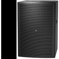
The Versarray™ 112 Mk III Passive Ribbon Tweeter Line Source Array speaker system consists of a 12" Neo Black Widow® woofer combined with a Neodymium based Peavey RD™ 2.6 Mk III ribbon tweeter in a cabinet with a simple, quick, yet flexible rigging system. Designed to provide modular coverage of small to medium venues, and intended for use with the companion Versarray™ Mk III Sub models, the Versarray™ 112 Mk III offers excellent versatility with a very high performance capability. The two-way system consists of the following driver components: a 12" Black Widow® Neo series woofer with Neodymium magnet structure. Capable of over 500W of continuous power handling (AES Std 2-1984), the woofer can handle a lot of sheer power. The high frequencies are handled by two Peavey® RD™ 2.6 Mk3 ribbon tweeters utilizing a composite sandwich ribbon, a Neodymium magnet system, and a low distortion CLEAR FORM™ waveguide.
Designed to be used in conjunction with a compatible DSP based loudspeaker signal processor, such as a Peavey Digitool ™ , Nion ® or MediaMatrix ® system, with the Peavey factory settings in use, the Versarray ™ 112 Mk III can perform to modern standards of excellence, and handily exceed the competitions audible performance.
The FlyQWIK™ fully articulated hardware rigging system provides for a classic straight line-array configuration, or a number of different angling options, providing easy aiming of the system. Angles between the array modules is adjustable from 0 degrees (straight), to 15 degrees in 2.5 degree increments. Total angle possible between two cabinets is 15 degrees.
Quick-lock pins are supplied with the rigging hardware to couple the Versarray™ 112 Mk III modules together and lock the angles between them into place, as well as for the rigging halo and fly bar configurations of a line array. The flexibility of the Versarray™ system allows the use of anywhere from 1 to 10 Versarray™ 112 Mk III modules in conjunction with Versarray™ 218 Mk III Subs. An optional special groundstack bracket set mounts to the Versarray 218 Mk III Sub, and allows up to three of the Versarray™ 112 Mk III 's to be mounted on top of the Versarray 218 Mk III Sub, and angled upward, for use on stage in a stadium seating situation.
Features
• 2-way Bi-Amp Ribbon Line Source Array SR System
- 12" Neo Black Widow® 4" VC Woofer
• 1000 watt program, 2000 watt peak power handling
- Ribbon Tweeters with Neo magnet and composite material sandwich ribbon
- Ribbon Tweeters mounted to our proprietary CLEAR FORM™ Waveguide
- 90 H by 15 V degree coverage pattern (per one cabinet)
- Easy aiming FlyQWIK™ hardware rigging system
- Angle adjustable in 2 1/2 degree increments, from 0 to 15 degrees total angle between adjacent cabinets
- Sound Guard™ tweeter protection, series capacitor for reliability
- Inputs are two Neutrik® Speakon® 4 pin jacks in parallel
- 18 mm 13 ply Baltic Birch enclosure with steel inner brackets
- Injection molded cabinet end caps, made from high impact material.
- Hammerhead™ polyurea black finish and black powder-coated cloth lined grilles
SPECIFICATIONS
Versarray™ 112 Mk III
Frequency Response, 1 meter on-axis, swept-sine in anechoic environment: 100 Hz to 20 kHz ( ± 3 dB, with processing)
Usable Low Frequency limit, -10 dB point: 85 Hz (with processing)
Power Handling:
Low Frequency Section: 500 W continuous 1,000 W program 2,000 W peak
High Frequency Section: 120 W continuous 240 W program 480 W peak
Sound Pressure Level, 1 Watt, 1 meter in anechoic environment:
Low Frequency Section: 97 dB SPL, (2.83 V input)
High Frequency Section: 101 dB SPL, (4.0 V input for 16 ohm wiring)
Maximum Sound Pressure Level (1 meter) * :
Low Frequency Section: 124 dB SPL continuous 130 dB SPL peak
High Frequency Section: 122 dB SPL continuous 128 dB SPL peak *Note: This spec is for one module at 1 meter, a line array of 6 units has much higher output at distance due to line source effect where SPL falls off at 3 dB per distance doubling rather than 6 dB
Nominal Radiation Angle measured at -6 dB point of polar response: 90 degrees Horizontal by 15 degrees Vertical (One module only, straight line array of more than 1 module narrows vertical dispersion accordingly)
Transducer Complement:
Low Frequency Section: 1x 12 in. Woofer, 1244 Neo Black Widow 4 VC Woofer, in a sealed box
High Frequency Section: 2x 4.75 in. Ribbon Tweeters Two RD™ 2.6 Mk III Peavey Ribbon Tweeters, on a waveguide
Box Tuning Frequency (Sealed): Low Frequency Section: 88 Hz
Electroacoustic Crossover Point, Peavey Active Digital Crossover: (Applies to VSX™, Digitool® and Nion®/MediaMatrix® settings provided by Peavey)
Sub - Low Frequency: 125 Hz at 24dB/octave
Low Frequency - High Frequency: 1950 Hz at 24dB/octave
Recommended Active Crossover Frequency Region and Slope: Sub -Low Frequency: 125 Hz at 24dB/octave LR Low Frequency -High Frequency: 2000 Hz at 24dB/octave LR
Impedance (Z):
Low Frequency: Nominal: 8.0 Ohms, Minimum: 6.5 Ohms
High Frequency: Nominal: 16 Ohms, Minimum: 13.6 Ohms
(Special Note: Ribbon tweeters are capacitor coupled so use with switching amps is allowed.)
Input Connections: 2x Neutrik ® 4-pin Speakon * jack
Enclosure Materials & Finish: 18 mm 13 ply Baltic Birch plywood finished in a tough Hammerhead™ polyurea black finish, with injection molded end caps and horn, with a perforated steel grille finished in black powder coat paint and a cloth liner inside. Inner steel frame and backing plates for rigging hardware.
Mounting provisions: Custom array brackets and hardware, and a custom array angle adjustment system are included with each module. Quick release pins are included with each cabinet.
Dimensions (H x W x D):
Front: 15.13 in. x 25.06 in. x 15.19 in.
384 mm x 637 mm x 386 mm
With Rigging hardware and Pins:
15.13 in. x 27.13 in. x 16.75 in.
321 mm x 689 mm x 426 mm
Net Weight: 66 Lbs. (30.0 kg) {includes all cabinet associated rigging hardware for each cabinet, including quick-lock pins, etc.}
Companion Subwoofers (sold separately): Versarray™ 218 Mk III Sub double 18" Lo Max® woofer subwoofer
Optional Accessories:
3 foot speaker cable, with 16 gauge 4 conductor wires with 4-pin to 4-pin Neutrik plugs (Peavey part number 00585240); and 10mm Quick Release Positive Lock Pins for array rigging.
Flying/Rigging Options:
Versarray ™ Mk III HALO
Versarray ™ Mk III FLY BAR, 6FT LENGTH
Versarray™ Mk III SUB SUPPORT FRAME
Versarray ™ Mk III FLY BAR, 2FT LENGTH
![| Frequency [Hz] | dB SPL | | -------------- | ------ | | 12 | 70 | | 15 | 85 | | 20 | 95 | | 30 | 100 | | 40 | 102 | | 50 | 103 | | 60 | 104 | | 70 | 105 | | 80 | 106 | | 90 | 107 | | 100 | 108 | | 110 | 109 | | 120 | 110 | | 130 | 111 | | 140 | 112 | | 150 | 113 | | 160 | 114 | | 170 | 115 | | 180…](/content/2026/05/935357/images/9ca8e2468b64555ae035dfc417d43a9def1d80932f09a5365a09977138d63cd5.jpg)
![| Frequency [Hz] | Level [dB] | | -------------- | ---------- | | 250 | 3.5 | | 500 | 4.0 | | 1k | 8.5 | | 2k | 12.0 | | 4k | 14.5 | | 8k | 13.0 | | 16k | 17.0 | | 18k | 16.5 |](/content/2026/05/935357/images/ec224bb9d07bb0fc8d40ebbe26ea8f7d64461062ffb8d6d3dbbeaa43e667a069.jpg)
![| Frequency [Hz] | Angle Degree | | -------------- | ------------ | | 250 | 250 | | 500 | 180 | | 1K | 120 | | 2K | 90 | | 4K | 100 | | 10K | 95 |](/content/2026/05/935357/images/500c6ac55515de544c1ae9209f5ef0f32a4fa1e7715038d710c75185d469fdb0.jpg)
![| Frequency [Hz] | Angle Degree | | -------------- | ------------ | | 250 | 220 | | 500 | 100 | | 750 | 120 | | 1000 | 110 | | 1250 | 80 | | 1500 | 40 | | 1750 | 20 | | 2000 | 15 | | 2250 | 10 | | 2500 | 5 | | 2750 | 3 | | 3000 | 2 | | 3250 | 1 | | 3500 | 1 | | 3750 | 1 | | 4000 | 1 | | 4250 | 1 | |…](/content/2026/05/935357/images/f66b04a2a22b0af95aa61c2769b87a109fe438452e92460513dd86238b620066.jpg)
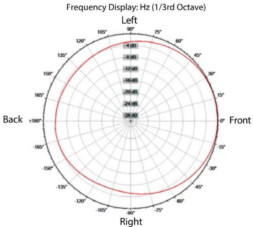
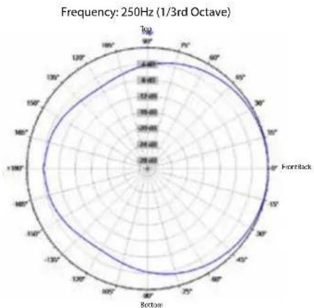
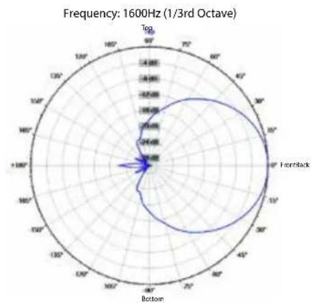
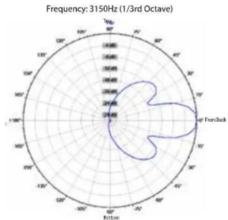
Horizontal Polar Patterns
Frequency: 200Hz (1/3rd Octave)

Frequency: 400Hz (1/3rd Octave)
Frequency: 250Hz (1/3rd Octave) Frequency: 315Hz (1/3rd Octave)

Frequency: 500Hz (1/3rd Octave)

Frequency: 630Hz (1/3rd Octave)

Frequency: 800Hz (1/3rd Octave)

Frequency: 1000Hz (1/3rd Octave)
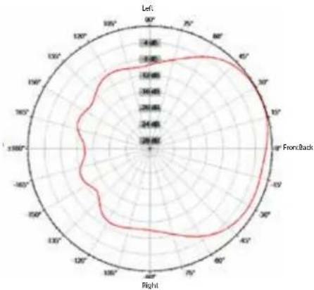
Frequency: 1250Hz (1/3rd Octave)

Frequency: 1600Hz (1/3rd Octave)

Frequency: 2000Hz (1/3rd Octave)

Frequency: 2500Hz (1/3rd Octave)


Frequency: 3150Hz (1/3rd Octave)
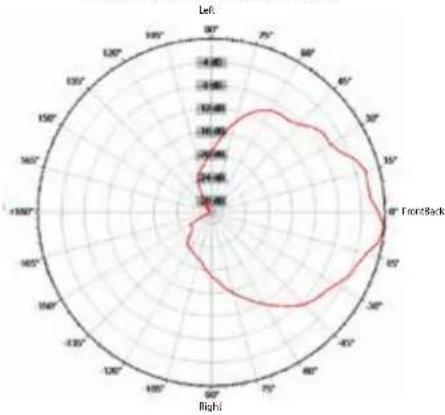
Frequency: 4000Hz (1/3rd Octave)

Frequency: 5000Hz (1/3rd Octave)

Frequency: 6300Hz (1/3rd Octave)

Frequency: 8000Hz (1/3rd Octave)

Frequency: 10000Hz (1/3rd Octave)
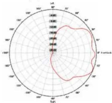
Frequency: 12500Hz (1/3rd Octave)

Frequency: 16000Hz (1/3rd Octave)

Frequency Display: Hz (1/3rd Octave)
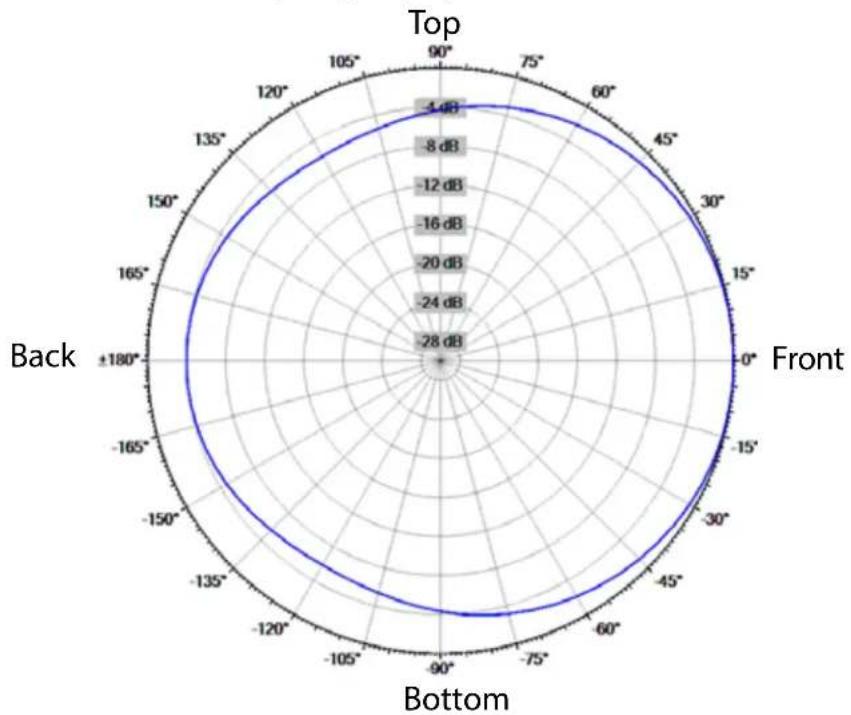
Vertical Polar Patterns







Frequency: 12500Hz (1/3rd Octave)

Frequency: 16000Hz (1/3rd Octave)

Warning! Do not feed a full-range signal to the tweeters in the Versarray™ 112 Mk III ! This could damage the tweeters!
It is recommended that for set-up or testing purposes, a high frequency sweep starting or ending no lower than 300 Hz be used to verify that the tweeters are connected to the high frequency output of the crossover/processor. If the wiring has been swapped, and the signal is mistakenly fed to the woofers, output will fall off significantly above 5 kHz. Always double-check and test your wiring before applying any music signals to the system! The ribbon tweeters are connected to the Neutrik® Speakon® pins 2+ and 2-, as per industry standards.
CAUTION! Ribbon Tweeters do not exhibit audible signs of distress when overloaded! It is possible to exceed the physical and/or thermal limits by overloading the unit suddenly with excess power, even though there are no obvious sounds of distress.
CAUTION! In order to prevent damage to the ribbon tweeters, keep the Versarray™ 112 Mk III system away from metal filings at all times. Do not expose ribbons to blasts of air, and do not use canned air to spray the ribbons, as this can result in damage. Do not expose ribbons to liquids or caustic fumes, and keep away from salt spray.
Frequency Response
This measurement is useful in determining how accurately a given unit reproduces an input signal. The frequency response of the Versarray ™ 112 Mk III is measured at a distance of 1 meter using a swept-sine input signal. As shown in Figure A, the selected drivers in the Versarray ™ 112 Mk III combine to give a smooth frequency response with the recommended signal processing.
Directivity
Beamwidth is derived from the -6 dB points from the polar plots which are measured in a whole space anechoic environment. Q and Directivity Index are plotted for the on-axis measurement position. These are specifications that provide a reference to the coverage characteristics of the unit. These parameters provide insight for proper placement and installation in the chosen environment. The blending of the components of the Versarray™ 112 Mk III and the settings on the Peavey® Digitool™ Live speaker processor (or other suitable speaker processor) and crossed over with the Versarray™ 112 Mk III pre-sets, exhibit a desirable beamwidth and directivity (as shown in Figures B, C and D) suitable for sound reinforcement applications.
Power Handling
There are many different approaches to power handling ratings. Peavey rates this loudspeaker system's components power handling using the AES Standard 2-1984. Using audio band pink noise of the proper range for each driver, with peaks of four times the RMS level, and then running the signal through the Peavey® Digitool™ Live speaker processor and crossover (or other suitable speaker processor) with the Versarray™ 112 Mk III pre-sets, this strenuous test signal assures the user that every portion of this system can withstand today's high technology music.
NOTE: Before you fly the array, be sure to inspect the rigging and flying hardware to insure that it is mechanically sound and has not been damaged, there should be no significant distortion of the shape of the coupling brackets, cabinet brackets, Halo or fly bar, and the hardware should be checked for tightness.
This Crest loudspeaker should be suspended overhead only in accordance with the procedures and limitations specified in the User's Manual and possible manual update notices. This system should be suspended with certified rigging hardware by an authorized rigging professional and in compliance with local, provincial or national suspension ordinances. ALWAYS USE PROPER GRADE HARDWARE.
CAUTION: Before attempting to suspend this speaker, consult with a certified structural engineer. Speaker can fall from improper suspension, resulting in serious injury and property damage. Use only the correct mating hardware. All associated rigging is the responsibility of others. Maximum enclosure angle 30 degrees. Failure to follow proper rigging specifications listed in the manual may result in injury or death.
Whenever possible, in addition to the nominal primary mounting method, use a suitable safety chain or wire rope attached to one of the other groups of fly points, and firmly attached to a suitable structural member as indicated by a certified structural engineer. CAUTION: ALWAYS USE SAFETY CHAIN OR WIRE ROPE.
IF ANY OF THE RIGGING, OR THE HALO OR FLY BAR HAS BEEN DAMAGED OR DISTORTED, DO NOT USE, AND DO NOT FLY THE ARRAY UNTIL
THEY CAN BE REPLACED OR REPAIRED!
DO NOT USE THE PIVOT BAR OR ANGLE SLIDER BRACKET AS HANDLES TO TRANSPORT THE CABINETS!
DO NOT TRANSPORT THE CABINETS IN ARRAY CONFIGURATION COUPLED TOGETHER, EXCEPT WITH THE RECOMMENDED TRANSPORT CART AND IN THE STIPULATED MANNER FOR THAT CART. TRANSPORT IN SUCH AN UNAPPROVED MANNER VOIDS THE WARRANTY, AND THE SYSTEM WOULD BE CONSIDERED UNSAFE TO BE FLOWN AFTER SUCH AN UNAPPROVED TRANSPORT EVENT.
Use only the correct mating hardware. All associated rigging is the responsibility of others.
Correct use and seating of the Quick Release Push Lock Pins Used with all Versarray™ rigging hardware
When using the Quick Release Positive Lock Pins, when the Quick Release Push Lock Pins are inserted, they should be fully seated, so that the black shoulder near the end of the pin has been placed flush with the side of the bracket, or as far in as the pin hole cavity will allow it to be inserted.
You will have to fully depress the center push-button to do this.
You should not be able to pull these pins out unless the center push-button is fully depressed.
Versarray™ Mk3 Halo Use
Specific Instructions for flying and hanging the Versarray™ Mk III Halo will not be supplied. It provides and follows industry standards for attaching rigging and fly hardware, as well as providing for the currently popular practice of hanging the array via a single hang point that can be a suitably rated chain hoist motor system. Seek the recommendations of a certified structural engineer or an experienced rigging professional for any questions about this type of use of the Versarray™ Mk III Halo.
Instructions for maximizing the single point hang balance point options are provided in the Versarray™ Mk3 Halo Owner's Manual, due to the unique flexibility the Versarray™ system provides.
Hanging Versarray™112 Mk III Cabinets from a Versarray™ Mk III Halo
Assuming the Halo is in position just above the cabinet/s, on a motorized hoist or manually cranked hoist, proceed as follows.
- Remove the top front quick release lock pins, slide the front hang straps up and pin them in place using those pins, with the front hang straps extending upward. The strap should be sticking up approximately 2.13". Do this for both sides. See Fig.1 and 1a.

Figure 1

Figure 1a
Cabinet Hang
Strap
- Either lower the Versarray™ Mk III Halo to meet the cabinet, or raise the cabinet up to meet the Halo, with the cabinet straps guided into mating with the Halo ears on both sides at the same time. Pin the front straps in place using the pins from the Halo. See Fig. 2

Figure 2
- Remove the Pivot Bar hole pin, swing pivot bar up to mate with the center rear bottom Halo ear hole. The bottom hole on the Halo ear provides a zero angle between the Halo and the first cabinet, the upper hole an angle of 5 degrees between the Halo and the first cabinet. Pin the Pivot Bar to the desired hole using the pin from the Halo. See Fig. 3

Figure 3
- Adding the second Cabinet.
Remove the top front quick release lock pins, slide the front hang straps up and pin them in place extending upward. The strap should be sticking up approximately 2.13". Do this for both sides. See Fig.1 and 1a.
- Either lower the Halo and first cabinet to meet the second cabinet, or raise the second cabinet up to meet the first cabinet, with the second cabinet straps guided into mating with the first cabinet bottom strap slots. Pin the front straps in place using the pins from the first cabinet. See Fig. 4 and 4a.

Figure 4 Figure 4a
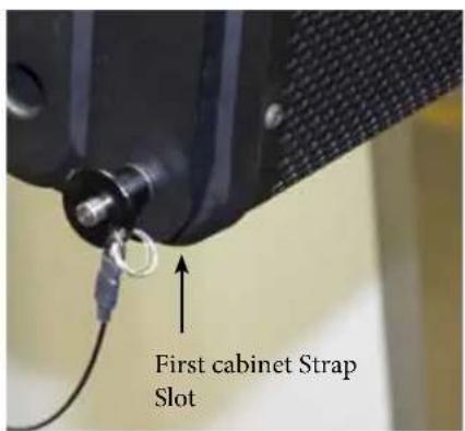
- Remove the Pivot Bar hole pin on the second cabinet, swing pivot bar up to mate with the Pivot Bar hole of the first cabinet. Pin the Pivot Bar into place using the bottom rear pin on the first cabinet. See Fig. 5 and 5a.

Figure 5

Figure 5a Alternate View

NOTE: Once the Pivot Bar hole pin is removed, the cabinet is free to swing through all possible angles, be sure to keep fingers, hands and your body out of the possible path of the cabinet hardware or the cabinet itself, to avoid injury.
With the first cabinet rigging in the default factory Lock position, that is, with the Angle Slider bracket lined up with it's arrow at LOCK, lined up with the LOCK arrow on the Angle Slider Rail, the angle between the first and second cabinets is not at a nominal set angle, it is an intermediate setting.
The angle the cabinets are set to can be read at the Angle arrow.
- The angle of the second cabinet can now be adjusted. To set the angle between the first cabinet and the second cabinet to a nominal amount, remove the Lock pin from the hole it is in, and slide the Angle Slider bracket. Angle Arrow to the desired angle as shown by the arrow labeled Angle on the Angle Slider Rail, and put a pin from the first cabinet (the one you removed from the Lock hole) into the Angle Pin hole on the Angle Slider bracket.
You can set the angle between the first cabinet and the second cabinet to be any of the following angles: 0 degrees, 2.5 degrees, 5 degrees, 7.5 degrees, 10 degrees, 12.5 degrees, and 15 degrees
As an example, see See Fig. 6, showing a set angle of 2.5 degrees.

Figure 6
The angle for 7.5 degrees uses a different set of arrows, due to the hardware bolt being in the way of a correctly located screened angle on the Angle Slider Rail using the Angle arrow on the Angle Slider bracket.
This is why there is an arrow that is an offshoot of the Primary Angle arrow on the Angle Slider bracket, just below it, labeled 7.5 degrees. This is lined up with the arrow marked 7.5 degrees on the Angle Slider rail. See Fig. 7.
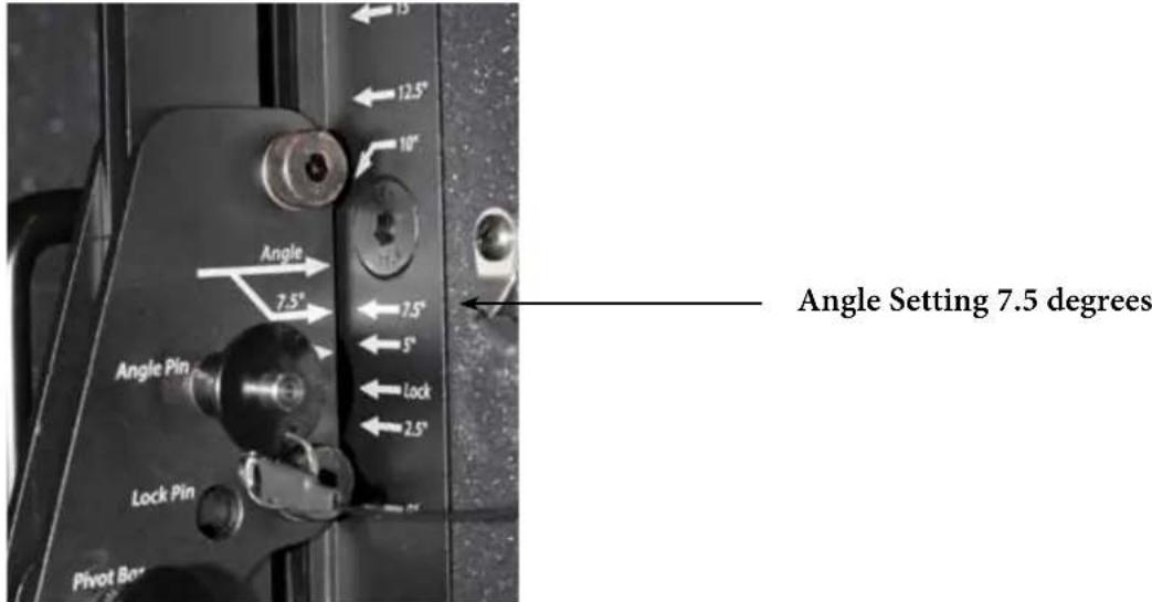
Figure 7
Adding additional cabinets follows this same basic hook-up progression, with the Angle Slider on the top cabinet of a given pair setting the angle between those two cabinets.
NOTE: Any Versarray™ Sub cabinets that might be flown in the same array off of the same Halo should be located at the top of the array, as they have no angle adjustment capability, and can only be hung at a 0 degree angle.
Alternate Method of Setting Angles Between Cabinets
Instead of following Step 6 (Hook-up Pivot Bar) and then Step 7 (Set Angle Between Cabinets), set the angle on the Angle Slider bracket and rail before un-pinning the Pivot Bar, and connecting it to the previous cabinet. Each method will work, but one will be more easily implemented with one person setting up the rig, versus having two or more people available.
Dismantling an Array
To take the line array down, you simply reverse the process, and remove one cabinet at a time, placing the rigging hardware into the nominal storage and transport positions.
Retract all the hang straps, and pin into place, place the Pivot Bar into the proper position to pin it into the Pivot Bar Hole, remove the pin from the Angle Pin hole, and slide the Angle Slide bracket into the LOCK position (LOCK arrow lined up with the other LOCK arrow), and pin into place. See Fig. 8.

Figure 8
Make sure that all the quick release lock pins are re-inserted into their default positions.
Cabinet hardware and rigging must be placed into the storage and transport positions, to move or transport the cabinets individually, or the product Warranty is voided.
The only exception is use of the Crest Audio® designed transport Carts, capable of transporting 4 Versarray™ 112 Mk III while in a straight line array configuration, with all cabinets set to 0 degrees. Instructions for the proper use of the Cart will be in the Cart Owner's manual.
Processor Settings
Versarray™ 112 Mk 3 Processor Settings and MLAS™ EQ packages.
Specific Settings for a Digitool® Live or Digitool MX16/MX32 ONLY
Single VR112 Mk 3 Cabinet w/VR 218 Sub (Starting point)
Front End EQ (before the crossover section)
The input channel of the Digitool is used to aid in the overall EQ of the VR112 Mk 3. One band is used for one of the infra-sonic filter sections, see below.
Two bands are used for static EQ of the VR 112 Mk 3 system, and three bands of EQ are then available for adjusting the EQ to match the varying number of cabinets, using the MLAS ™ technique as explained below.
Static EQ
PEQ -1.5 dB @ 298 Hz, BW = 0.60
PEQ -3.0 dB @ 9428 Hz, BW = 0.36
Variable EQ (depends on number of cabinets, see cabinet number chart below)
PEQ -X.X dB @ 180 Hz, BW = X.X
Infrasonic Filtering: Output Channel = VR 218 Mk 3 High Pass crossover = Linkwitz-Riley 24 dB/oct. @ 23 Hz;
High Pass12 dB/oct, 20 Hz, BW=1.9
Crossover settings:
VR218 Mk3 Subwoofer to VR112 Mk3 Crossover:
Sub= 24 dB/oct. Low Pass Linkwitz-Riley 24 dB/oct. @ 120 Hz, Sub Polarity Normal
Sub EQ (in output channel):
PEQ +4.5 dB @ 38 Hz, BW = 0.7;
PEQ -3.0 dB @ 55 Hz, BW= 0.50;
PEQ -2.5 dB @ 66 Hz, BW=0.5;
PEQ -8.5 dB @ 260 Hz, BW= 0.7
Woofer Output Channel Filters:
High Pass filter = 24 dB/oct. Bessel @ 186 Hz,
Low Pass filter = 24 dB/oct. Bessel @ 1280 Hz,
Tweeter Output Channel Filters: High Pass filter = 24 dB/oct. Bessel @ 3300 Hz
Woofer Polarity Normal, Tweeter Polarity Reversed
(Bessel Set Frequency NOT Normalized to the -3 dB point)
Special Note: These settings have been carefully selected to provide the best performance the Versarray™ 112 Mk 3 system is capable of, and provide maximum sound quality with good reliability.
Bessel filters have a non-intuitive frequency setting compared to Linkwitz-Riley or Butterworth filters, and may give the impression that there is a servere under-lap at the crossover frequency. This is not the case, and all factors have been taken into account, including the acoustic behavior of the drivers into the waveguide load. If you have any concerns or questions about crossover and EQ settings, please contact Peavey Transducer Engineering.
EQ after crossover (output channel):
Woofer EQ:
PEQ +4.0 dB @ 115 Hz, BW = 0.6
PEQ -6.0 dB @ 469 Hz, BW = 0.60
PEQ +1.0 dB @ 620 Hz, BW = 0.40
PEQ -2.0 dB @ 786 Hz, BW = 0.50
PEQ -2.0 dB @ 1000 Hz, BW = 0.60
PEQ -3.0 dB @ 1160 Hz, BW = 2.00
PEQ -1.5 dB @ 1400 Hz, BW = 0.30
Woofer Delay = 0.103 ms
Other Output Chanel
Tweeter EQ:
PEQ -2.5 dB @ 2.26 kHz, BW = 1.12
PEQ +2.0 dB @ 2.80 kHz, BW = 0.46
PEQ -2.0 dB @ 3.45 kHz, BW = 0.30
PEQ -3.0 dB @ 4.21 kHz, BW = 0.85
PEQ -1.5 dB @ 6.00 kHz, BW = 0.30
PEQ +2.5 dB @ 7.16 kHz, BW = 0.30
PEQ +5.0 dB @ 13.90 kHz, BW = 0.80
Tweeter Delay = 0.0 ms (none)
VR112 Mk3 Multi-Cabinet MLAS™ Settings For Peavey Digitool™ Live or MX16/MX32 ONLY
These settings provide for the EQ packages mentioned in the MLAS ™ section preceding this.
There is no need to change the level of the tweeters or the Subs relative to the 12" woofers with these settings used.
These settings are specific to the Peavey Digitool TM models, more general settings are shown after this section.
Special Note: These settings use varying degrees of Hi-shelf EQ instead of an overall level change for the whole tweeter band, in order to optimize the response even further than previous versions of the Versarray system.
Mild_Angle (2.5 to 5 deg angle between cabs)
PEQ Hi-Shelf Hi-Shelf Hi-Shelf Hi-Shelf
180Hz 3850Hz 4660Hz 5500Hz 6125Hz
One Cabinet -2 dB, BW=1.4 0 0 0 0
2 Cabinets -2 dB, BW=1.4 +2 dB, BW=1.4 0 0 0
3 Cabinets -2.5dB, BW=1.4 0 +3.5dB, BW=1.4 0 0
4 Cabinets -3 dB, BW=1.47 0 +5 dB, BW=1.4 0 0
6 Cabinets -3.5dB, BW=1.6 0 0 +6 dB, BW=1.4 0
8 Cabinets -4 dB, BW=1.6 0 +6dB, BW=1.4 0 +1 dB, BW=1.4 (190 Hz)
More_Angled (7.5 to 10 deg angle between cabs)
| PEQ | Hi-Shelf | Hi-Shelf | Hi-Shelf | Hi-Shelf | Hi-Shelf |
| 180Hz | 2700Hz | 3850Hz | 5500Hz | 6125Hz | |
| 2 Cabinets | -2 dB, BW=1.4 | +2.5dB, BW=1.4 | 0 | 0 | 0 |
| 3 Cabinets | -2.5dB, BW=1.4 | 0 | +4 dB, BW=1.4 | 0 | 0 |
| 4 Cabinets | -3 dB, BW=1.47 | 0 | +5.5dB, BW=1.4 | 0 | 0 |
| 6 Cabinets | -3.5dB, BW=1.6 | 0 | +6 dB, BW=1.4 | +1 dB, BW=1.4 |
J-Line_Section (12.5 to 15 deg angle between cabs)
| PEQ | Hi-Shelf | Hi-Shelf |
| 180Hz | 2515Hz | 2220Hz |
| 2 Cabinets | -2 dB,BW=1.4 | +2.5dB,BW=1.4 0 |
| 3 Cabinets | -2.5dB,BW=1.4 | +4.5dB,BW=1.4 0 |
| 4 Cabinets | -3 dB,BW=1.47 0 | +6 dB,BW=1.4 |
Straight-Line Section
| PEQ | Hi-Shelf | Hi-Shelf | Hi-Shelf | Hi-Shelf | Hi-Shelf |
| 180Hz | 3850Hz | 4660Hz | 5500Hz | 6000Hz | |
| 2 Cabinets | -2 dB, BW=1.4 | +1.5dB, BW=1.4 | 0 | 0 | +2 dB, BW=1.4 |
| 3 Cabinets | -2.5dB, BW=1.4 | +2.5dB, BW=1.4 | 0 | 0 | +2 dB, BW=1.4 |
| 4 Cabinets | -3 dB, BW=1.47 | 0 | +3.5dB, BW=1.4 | 0 | +2 dB, BW=1.4 |
| 6 Cabinets | -3.5dB, BW=1.6 | 0 | 0 | +4 dB, BW=1.4 | +2 dB, BW=1.4 |
| 8 Cabinets | -4 dB, BW=1.6 | 0 | 0 | +5.5dB, BW=1.4 | +2 dB, BW=1.4 |
| (190 Hz) | |||||
Bass-Boost – General EQ on top of MLAS sections and cabinet numbers
For Versarray 112 Mk3, Bass Boost Mode
| EQ bands listed below are PEQ's |
| +4 dB @ 125 Hz, BW=1.6 |
| +2 dB @ 162 Hz, BW=0.30 |
| -2.5 dB @ 183 Hz, BW=0.90 |
These are on top of (or in addition to) the regular VR 112 Mk3 crossover and EQ settings, as shown above.
These settings should only be used in conjunction with the complimentary Bass-Boost EQ on the VR215 Pro or VR218 Mk3/Pro, never just on the VR112's alone.
Shown below are the Bass-Boost settings for the VR-218 Mk3, which should only be used in conjunction with the complimentary settings on the VR112's.
For Versarray VR218 Mk 3, Bass Boost Mode
EQ bands listed below are PEQ's
-3.5 dB @ 24 Hz, BW=2.0
+4 dB @ 40 Hz, BW=1.6
+4 dB @ 63 Hz, BW=1.6
+4.5 dB @ 125 Hz, BW=1.6
-2 dB @183 Hz, BW=0.70
These are on top of (or in addition to) the regular VR218 Mk3 Subwoofer crossover and EQ settings, as detailed below:
Infrasonic Filtering:
Input Channel = HP12, 29 Hz, BW = 1.9
Output Channel = VR 218 Mk 3 High Pass crossover, Linkwitz-Riley 24 dB/oct. @ 23 Hz OR
a single LR 36 dB/oct. high pass set to 33 Hz
Crossover settings:
VR218 Mk3 Subwoofer Crossover (to VR112 Mk3):
Sub= 24 dB/oct. Low Pass Linkwitz-Riley 24 dB/oct. @ 120 Hz,
Sub Polarity: Normal
Sub EQ (in output channel):
PEQ +4.5 dB @ 38 Hz, BW= 0.70 (Q=2.39)
PEQ -3.0 dB @ 55 Hz, BW= 0.50 (Q=2.04)
PEQ -2.5 dB @ 66 Hz, BW= 0.50 (Q=2.04)
PEQ -8.5 dB @ 260 Hz, BW= 0.70 (Q=2.39)
SPECIAL NOTE: These settings have been carefully selected to provide the best performance the Versarray™ 112 Mk 3 system is capable of, and provide maximum sound quality with good reliability.
Bessel filters have a non-intuitive frequency setting compared to Linkwitz-Riley or Butterworth filters, and may give the impression that there is a severe under-lap at the crossover frequency. This is not the case, and all factors have been taken into account, including the acoustic behavior of the drivers into the waveguide load. If you have ANY concerns or questions about crossover and EQ settings, please contact Peavey Transducer Engineering.
Limiters
(DO NOT DEPEND ON THE LIMITER ALONE to prevent damage!)
Sensible output levels and amounts of boost should be kept in mind.
DIGITOOL® Live Limiter Settings
Input Gain Block= 18 dBu
Output Gain Block= 24 dBu
Power Amp Gain set to 40X (32 dB)
Versarray™ 218: Threshold: - 17.0 dB
Ratio: 20:1
Attack: 100 mS
Release: 500 mS
Versarray ™ 112:
Woofer: Threshold: - 20.0 dB
| Ratio: | 20:1 | |
| Attack: | 60 | mS |
| Release: | 600 | mS |
Ribbon: Threshold: - 25.0 dB
| Ratio: | 20:1 | |
| Attack: | 10 | mS |
| Release: | 100 | mS |
Input Limiter: Threshold: - 2 dB
| Ratio: | 20:1 | |
| Attack: | 50 | mS |
| Release: | 500 | mS |
Note: The Digitool® Live references the limiter settings to 0 dBFS, or the maximum digital output levels of the system.
The settings above provided for the Digitool ® Live will also work for the Digitool ® MX16 and MX32. Settings for the NION ® series can be found at the Peavey web site.
Use of Speaker Processors Other than the Digitool ® , NION ® , or MediaMatrix ®
If using other brands of speaker processors, it is up to the user to verify that the settings used match the settings of the provided parameters as manifest in the recommended models of Processors.
Bessel filters were used for the crossover on the Versarray ™ 112 Mk 3, and these do not have a standardized -3 dB or -6dB roll-off point, like Linkwitz-Riley or Butterworth filters do. The exact settings for use with the Digitool ® Live, MX16 and MX32 are provided, and settings for the NION ® are provided at the Crest website.
General Processor Settings
Versarray™ 112 Mk 3 Processor Settings - General Settings for a Processor that uses Q Instead of BW
Single VR112 Mk 3 Cabinet w/VR 218 Sub (Starting point)
Front End EQ (before the crossover section)
Infrasonic Filtering: Input Channel = HP12, 20 Hz, Q=0.71; Output Channel = VR 218 Mk 3 High
Pass cross over = Linkwitz-Riley 24 dB/oct. @ 23 Hz
Crossover settings:
VR218 Mk3 Subwoofer to VR112 Mk3 Crossover:
Sub= 24 dB/oct. Low Pass Linkwitz-Riley 24 dB/oct. @ 120 Hz, Sub Polarity Normal
Sub EQ (in output channel):
PEQ +4.5 dB @ 38 Hz, Q = 2.0
PEQ -3.0 dB @ 55 Hz, Q = 2.8
PEQ -2.5 dB @ 66 Hz, Q = 2.0
PEQ -8.5 dB @ 260 Hz, Q = 2.8
Woofer Output Channel Filters:
High Pass filter = 24 dB/oct. Bessel @ 173 Hz - 3 dB, - 6 dB at 131 Hz,
Low Pass filter = 24 dB/oct. Bessel @ 1340 Hz - 3 dB, - 6 dB at 1710 Hz
Tweeter Output Channel Filters: High Pass filter = 24 dB/oct. Bessel @ 2700 Hz - 3 dB, - 6 dB at 2100 Hz
Woofer Polarity - Normal, Tweeter Polarity - Reversed
(Bessel set frequency not always normalized to the -3 dB point, check your processors method of the Bessel filter set point. See Bessel filter substitution guide at the end of this section.)
EQ after crossover (output channel):
Woofer EQ:
PEQ +4.0 dB @ 115 Hz, Q = 2.4
PEQ -6.0 dB @ 469 Hz, Q = 2.4
PEQ +1.0 dB @ 620 Hz, Q = 3.6
PEQ -2.5 dB @ 786 Hz, Q = 2.8
PEQ -2.0 dB @ 1000 Hz, Q = 2.4
PEQ -3.5 dB @ 1160 Hz, Q = 0.67
PEQ -1.5 dB @ 1400 Hz, Q = 4.2
PEQ -1.5 dB @ 298 Hz, Q = 2.4
Woofer Delay = 0.103 ms
Tweeter Output Chanel
Tweeter EQ:
PEQ -2.5 dB @ 2.26 kHz, Q = 1.26
PEQ +2.0 dB @ 2.80 kHz, Q = 3.2
PEQ -2.0 dB @ 3.45 kHz, Q = 4.2
PEQ -3.0 dB @ 4.21 kHz, Q = 1.7
PEQ -1.5 dB @ 6.00 kHz, Q = 4.2
PEQ +3.5 dB @ 7.16 kHz, Q = 4.2
PEQ +5.0 dB @ 13.90 kHz, Q = 1.3
PEQ -3.0 dB @ 9428 Hz, Q = 4.2
Tweeter Delay = 0.0 ms (none)
MLAS TM Multi-cabinet EQ Package Settings, Q parameters
Mild_Angle (2.5 to 5 deg angle between cabs)
PEQ Hi-Shelf Hi-Shelf Hi-Shelf Hi-Shelf 180Hz 3850Hz 4660Hz 5500Hz 6125Hz
| One Cabinet -2 dB,Q=1 | 0 | 0 | 0 | 0 | |
| 2 Cabinets -2 dB,Q=1 | +2 dB,Q=1 | 0 | 0 | 0 | |
| 3 Cabinets -2.5dB,Q=1 | 0 | +3.5dB,Q=1 | 0 | 0 | |
| 4 Cabinets -3 dB,Q=.94 | 0 | +5 dB,Q=1 | 0 | 0 | |
| 6 Cabinets -3.5dB,Q=.89 | 0 | 0 | +6 dB,Q=1 | 0 | |
| 8 Cabinets -4 dB,Q=.89 | 0 | +6dB,Q=1 | 0 | +1 dB,Q=1(190 Hz) |
More_Angled (7.5 to 10 deg angle between cabs)
| PEQ | Hi-Shelf | Hi-Shelf | Hi-Shelf | Hi-Shelf | Hi-Shelf |
| 180Hz | 2700Hz | 3850Hz | 5500Hz | 6125Hz | |
| 2 Cabinets | -2 dB,Q=1 | +2.5dB,Q=1 | 0 | 0 | 0 |
| 3 Cabinets | -2.5dB,Q=1 | 0 | +4 dB,Q=1 | 0 | 0 |
| 4 Cabinets | -3 dB,Q=.94 | 0 | +5.5dB,Q=1 | 0 | 0 |
| 6 Cabinets | -3.5dB,Q=.89 | 0 | 0 | +6 dB,Q=1 | +1 dB,Q=1 |
J-Line_Section (12.5 to 15 deg angle between cabs)
PEQ Hi-Shelf Hi-Shelf 180Hz 2515Hz 2220Hz
| 2 Cabinets | -2 dB,Q=1 | +2.5dB,Q=1 | 0 |
| 3 Cabinets | -2.5dB,Q=1 | +4.5dB,Q=1 | 0 |
| 4 Cabinets | -3 dB,Q=.94 | 0 | +6 dB,Q=1 |
Straight-Line Section
PEQ Hi-Shelf Hi-Shelf Hi-Shelf Hi-Shelf 180Hz 3850Hz 4660Hz 5500Hz 6000Hz
| 2 Cabinets | -2 dB,Q=1 | +1.5dB,Q=1 | 0 | 0 | +2 dB,Q=1 |
| 3 Cabinets | -2.5dB,Q=1 | +2.5dB,Q=1 | 0 | 0 | +2 dB,Q=1 |
| 4 Cabinets | -3 dB,Q=.94 | 0 | +3.5dB,Q=1 | 0 | +2 dB,Q=1 |
| 6 Cabinets | -3.5dB,Q=.89 | 0 | 0 | +4 dB,Q=1 | +2 dB,Q=1 |
| 8 Cabinets | -4 dB,Q=.89 | 0 | 0 | +5.5dB,Q=1 | +2 dB,Q=1 |
| (190 Hz) | |||||
Bass-Boost – General EQ on top of MLAS sections and cabinet numbers For Versarray 112 Mk3
EQ bands listed below are PEQ's +4 dB @ 125 Hz, Q=0.89 +2 dB @ 162 Hz, Q=4.2 -2.5 dB @ 18325 Hz, Q=1.5
These are on top of (or in addition to) the regular VR 112 Mk3 crossover and EQ settings, as shown above.
These settings should only be used in conjunction with the complimentary Bass-Boost EQ on the VR215 Pro or VR218 Mk3/Pro, never just on the VR112's alone.
Shown below are the Bass-Boost settings for the VR 218 Mk3, which should only be used in conjunction with the complimentary settings on the VR 112's.
For Versarray VR218 Mk 3
EQ bands listed below are PEQ's
-3.5 dB @ 24 Hz, Q=0.67
+4 dB @ 40 Hz, Q=0.89
+4 dB @ 63 Hz, Q=0.89
+4.5 dB @ 125 Hz, Q=0.89
-2 dB @183 Hz, Q=2
These are on top of (or in addition to) the regular VR218 Mk3 Subwoofer crossover and EQ settings, as detailed below:
Infrasonic Filtering:
Input Channel = HP12, 29 Hz, BW = 1.9
Output Channel = VR 218 Mk 3 High Pass crossover, Linkwitz-Riley 24 dB/oct. @ 23 Hz OR
a single LR 36 dB/oct. high pass set to 33 Hz
Crossover settings:
VR218 Mk3 Subwoofer Crossover (to VR112 Mk3):
Sub= 24 dB/oct. Low Pass Linkwitz-Riley 24 dB/oct. @ 120 Hz,
Sub Polarity: Normal
Sub EQ (in output channel):
PEQ +4.5 dB @ 38 Hz, BW= 0.70 (Q=2.39)
PEQ -3.0 dB @ 55 Hz, BW= 0.50 (Q=2.04)
PEQ -2.5 dB @ 66 Hz, BW= 0.50 (Q=2.04)
PEQ -8.5 dB @ 260 Hz, BW= 0.70 (Q=2.39)
Approximate a Bessel Using a Linkwitz-Riley and a PEQ
If you have filter sections to burn, then a Bessel filter can be approximated using a LR filter cascaded with a PEQ.
Using the -3 dB set point frequency of the Bessel high pass filter, multiply that times 0.667, and use that number to set a Linkwitz-Riley filter at its -6 dB set point.
Then, add a PEQ with the following parameters:
-1.5 dB, at 0.81 times the -3 dB set point of the Bessel filter, with a BW of 2.0 (or a Q of 0.667)
Example:
To approximate a 24 dB/oct. Bessel high pass filter set to a -3 dB point at 2700 kHz, set a LR24 to 1.80 kHz, and a PEQ to -1.5 dB at 2187 Hz, BW=2.0 (Q=0.667)
This makes the amplitude and phase come out very close to the Bessel responses.
More examples:
For a 24 dB/oct. Bessel high pass at 173 Hz, set a LR24 to 115 Hz, with a PEQ set to: -1.5 dB at 140 Hz, bw=2.0 (Q=0.667)
For a 24 dB/oct. Bessel low pass at 173 Hz, set a LR24 to 346 Hz, with a PEQ set to: -1.5 dB at 213 Hz, bw=2.0 ( Q= 0.667 )
Note: Bessel set point frequency is -3 dB down point using this formula, LR set point frequency is defined as -6 dB down point.
Limiter Settings for Processors Other Than Digitool
The drivers in the Versarray™ 112 Mk3 are professional grade and can take a lot of music power, as well as long term thermal exposure. In setting the limiting thresholds for systems other than the called out Digitool combined with the Crest power amps, the VR 112 Mk3 components can be protected by observing the following limits to the drive voltages applied.
12" Neo Black Widow® woofer can handle 500W continuous per the AES Std. 2-1984, which is conducted in free air for 2 hours. Within the cabinet and when combined with the heat from the ribbon tweeters, this is reduced to 400W very long term (8 hours or more).
At the nominal effective impedance of the woofer over it's operating band, this equates to a long term drive voltage of 51.0 VAC, and a peak signal capability of 114 VAC peak when the signal has a crest factor of 12 dB or more.
The RD ™ 2.6 Mk3 ribbon tweeters can handle 60W each continuous per the AES Std. 2-1984. Within the cabinet, and when combined with the heat from the woofer, this is reduced to 40W very long term (8 hours or more). At the nominal effective impedance of the ribbons over their operating band, this equates to a long term drive voltage of 33.4 VAC, and a peak signal capability of 80.8 VAC peak when the signal has a crest factor of 12 dB or more. Note that the tweeters are wired in series for a 16 ohm load.
It is recommended that the compressor/limiter settings be adjusted so that the long term power to the drivers does not exceed the maximum specified voltages, when those amplifier channels are loaded with the appropriate driver, and that the peak voltages are not allowed to exceed the recommended levels while the system is at the long term operating temperature.
We strongly recommend that a power amp be used with a peak voltage rating that is not substantially higher than the peak voltage rating of the driver it is connected to. There will be no further significant increase in SPL, and a much higher chance that an accident or mistake will damage the speaker system.
Paralleling Versarray™ 112 Mk3 drivers on one amp channel
The ribbon tweeters impedance is set permanently to 16 ohms. In 16 ohm impedance configuration, we do not recommend paralleling 8 cabinet's high frequency sections together off of one amplifier channel, even if the amp is rated for 2 ohm operation. This also applies to the 12" woofers, we do not recommend paralleling 4 cabinet's low frequency sections together.
In general, avoid loading a 2 ohm rated amp all the way down to 2 ohms, the Versarray™ 112 Mk 3 system is revealing enough to highlight any roughness or harshness when the amp is on the edge of it's capabilities. We recommend keeping the amp load above 2.6 ohms when the amp is rated for 2 ohm operation.
Versarray™ Driver Components Maximum Input Voltages
Versarray™ 218 Mk3 Subwoofer: 89 VRMS continuous, 178 VRMS peak or momentary (with proper infrasonic and low pass filters engaged)
Versarray™ 112 Mk3 Woofer: 57 VRMS continuous, 114 VRMS peak or momentary (with proper band pass crossover filters used)
Versarray™ 112 Mk3 Tweeters:
16 ohm impedance configuration: 40.4 VRMS continuous, 80.8 VRMS peak or momentary (with proper high pass crossover filter used)
We strongly recommend that a power amp be used with a peak voltage rating that is not substantially higher than the peak voltage rating of the driver it is connected to. There will be no further significant increase in SPL, and a much higher chance that an accident or mistake will damage the speaker system.
CREST Power Amp Peak Output Voltages
Pro-LITE® 7.5 Maximum RMS Voltage Output - 124 volts
Pro-LITE® 5.0 Maximum RMS Voltage Output - 105 volts
Pro-LITE® 3.0 Maximum RMS Voltage Output - 71 volts
Pro-LITE® 2.0 Maximum RMS Voltage Output - 56 volts
older models
CREST Power Amp Peak Output Voltages
Pro 9200 Maximum RMS Voltage Output - 113 volts
Pro 8200 Maximum RMS Voltage Output - 90 volts
Pro 7200 Maximum RMS Voltage Output - 75 volts
Pro 5200 Maximum RMS Voltage Output - 52 volts
Recommended Crest Audio ® Power Amps for Use with the Versarray ™ system.
Versarray™ 218 Mk3 Subwoofer: Pro-LITE® 7.5 (One channel driving each woofer in the enclosure separately.)
Versarray™ 112 Mk3 Woofer: Pro-LITE® 5.0 (No more than 3 woofers per channel)
Versarray™ 112 Mk3 Tweeters: Pro-LITE® 3.0 (No more than 6 tweeters per channel)
Processor Setting Parameters
For processor's that use the parameter “Q” in octaves instead of bandwidth, here is a chart to convert from BW to Q. NOTE: Q is not as well defined as bandwidth, so some processors may have Q settings that do not exactly correspond to the chart conversions, they may need to be set to one click higher or
lower on the device provided Q range than the chart indicates.
Bandwidth (BW) to Q Chart
BW Q.
| 0.30 | 4.8 |
| 0.34 | 4.2 |
| 0.36 | 4.0 |
| 0.40 | 3.6 |
| 0.45 | 3.2 |
| 0.50 | 2.8 |
| 0.60 | 2.4 |
| 0.71 | 2.0 |
| 0.85 | 1.67 |
| 0.89 | 1.60 |
| 0.90 | 1.5 |
| 0.94 | 1.47 |
| 1.10 | 1.28 |
| 1.12 | 1.26 |
| 1.4 | 1.0 |
| 2.0 | 0.67 |
Check with Crest Audio ® , or visit the Crest Audio ® web site at:
https://peaveycommercialaudio.com/versarray
for the latest crossover and EQ setting information
INFORMATION ON THE FLYING HARDWARE FOR THE
Versarray™ 112 Mk3 (Available Separately)
CAUTION! Before attempting to suspend any Versarray™ Rigging Hardware with or without speakers hung from it, consult a certified structural engineer. The Halo/Fly Bar and/or speaker array can fall from improper suspension, resulting in serious injury and property damage. Use only the correct mating hardware. All associated rigging is the responsibility of others.
This Crest loudspeaker should be suspended overhead only in accordance with the procedures and limitations specified in the User's Manual and possible manual update notices. This system should be suspended with certified rigging hardware by an authorized rigging professional and in compliance with local, provincial or national suspension ordinances.
Whenever possible, in addition to the nominal primary mounting method, use a suitable safety chain or wire rope attached to one of the other groups of fly points, and firmly attached to a suitable structural member as indicated by a certified structural engineer. CAUTION: ALWAYS USE SAFETY CHAIN OR WIRE ROPE.
Crest Audio® Versarray™ Mk III Halo Crest FG# 03617370
Connects Versarray™ 112 and Versarray™ Pro 215 Sub speakers to overhead rigging.
Provides four M20 X 2.5mm thread forged steel eyebolts for traditional rigging on the top of the Halo; Halo center bar has 7 single-point hang locations to balance the Halo, and an optional 2 foot fly bar increases the number of separate and distinct balance points to 29. Includes quick-lock pins to mate to the first VR112 cabinet in a line.
Includes the bolts for the optional 2 foot or 6 foot Fly Bar.
Specifications:
Overall Dimensions, Including Pins and Eyebolts, etc. H x W x D:
11.63" X 27.44" X 20.63" (29.5 cm X 69.7 cm X 52.4 cm)
Halo Only Dimensions H x W x D: 11.63" X 25.50" X 20.63" (29.5 cm X 64.8 cm X 52.4 cm)
Weight: 64 lbs.
Material: All steel construction, 2" by 3" welded steel frame tubing with 3/16" wall thickness, center bar 1 / 2 " thick by 3" solid steel with seven 23mm rigging holes along the center of it's length, Halo coupling mounts for the cabinet front hang straps are dual 1/8" thick steel plates, one pair on each side.
Finish: Entire Halo is flat black powder coated paint finish.
Working Load Limit: 400 kg / 881 lbs. for Ultimate Strength Design Factor of 10:1 (This meets PLASA North America criteria and typically exceeds local USA safety requirements.)
Working Load Limit: 334 kg / 734 lbs. for Ultimate Strength Design Factor of 12:1 (This is in compliance with the European Union mandated Safety Factor)
Maximum Number of Versarray™ 112 Mk3 passive cabinets: 10 Maximum Number of Versarray™ 112 Pro Powered cabinets: 10
Maximum Number of Versarray ™ Pro 215 Sub cabinets: 5 (Note: VRPro 215 Sub cabinets do NOT articulate or angle, they must be hung at a zero degree angle. Therefore, we recommend that they be hung at the top of a line.)
Can fly up to 5 Versarray™ Pro 215 Subs, or 10 Versarray™ 112 Mk3 or Pro 2-Ways
Maximum Combined Number of Versarray™ 112 Mk3 or Pro 2-Ways and Versarray™ Pro 215 Sub cabinets:
MIX OF SUBS VERSUS 2-Ways
| Subs | Two-Ways |
| 0 | 10 |
| 1 | 8 |
| 2 | 6 |
| 3 | 4 |
| 4 | 2 |
| 5 | 0 |
Maximum Combined Pull-Back Angle, Two or less Subs in the hang: 30 degrees Maximum Pull-Back Angle, more than 2 Subs in the hang: 15 degrees
NOTES:
The ultimate strength for the Versarray™ Mk3 loudspeaker system rigging hardware was determined utilizing calibrated and certified pull tests.
More complete information on the Crest Audio® Versarray™ FlyQWIK™ Rigging System and the Mk III Halo can be found in the unit's Owner's manual, or by contacting Crest Audio®.
Design and specifications subject to change without notice.

CAUTIONS
WARNING!
IMPORTANT INFORMATION FOR STRUCTURAL ENGINEER AND RIGGING PERSONNEL.
Before you fly the array, be sure to inspect the rigging and flying hardware to insure that it is mechanically sound and has not been damaged. There should be no significant distortion of the shape of the Halo coupling ears, cabinet straps, Angle Slider bracket or Rail, Pivot Bar or a fly bar, and the hardware should be checked for tightness.

CAUTIONS:
IF ANY OF THE BRACKETS, RAILS, CABINET STRAPS, PIVOT BAR OR THE FLY BAR HAS BEEN DAMAGED OR DISTORTED, DO NOT USE, AND DO NOT FLY THE ARRAY UNTIL THEY CAN BE REPLACED OR REPAIRED!

DO NOT USE THE PIVOT BARS AS HANDLES TO TRANSPORT THE CABINETS!


www.peaveycommercialaudio.com
Warranty registration and information for U.S. customers available online at
www.peaveycommercialaudio.com/warranty
or use the QR tag below

Features and specifications subject to change without notice
Crest Audio 5022 HWY 493 N. Meridian, MS 39305 (601) 483-5365 FAX (601) 486-1278

Logo referenced in Directive 2032/98/EC Ansec 10
The bar is the essential for opening of new panels and
is applied only to equipment manufactured after

- VERSARRAY™ 112 MK III
- PASSIVE ENCLOSURE
- PRODUCT SPECIFICATIONS
- CREST AUDIO
- FEATURES
- SPECIFICATIONS
- HORIZONTAL POLAR PATTERNS
- FREQUENCY RESPONSE
- DIRECTIVITY
- POWER HANDLING
- CORRECT USE AND SEATING OF THE QUICK RELEASE PUSH LOCK PINS USED WITH ALL VERSARRAY™ RIGGING HARDWARE
- VERSARRAY™ MK3 HALO USE
- HANGING VERSARRAY™112 MK III CABINETS FROM A VERSARRAY™ MK III HALO
- ALTERNATE METHOD OF SETTING ANGLES BETWEEN CABINETS
- DISMANTLING AN ARRAY
- PROCESSOR SETTINGS
- VR112 MK3 MULTI-CABINET MLAS™ SETTINGS FOR PEAVEY DIGITOOL™ LIVE OR MX16/MX32 ONLY
- BASS-BOOST – GENERAL EQ ON TOP OF MLAS SECTIONS AND CABINET NUMBERS
- THESE ARE ON TOP OF (OR IN ADDITION TO) THE REGULAR VR 112 MK3 CROSSOVER AND EQ SETTINGS, AS SHOWN ABOVE
- THESE ARE ON TOP OF (OR IN ADDITION TO) THE REGULAR VR218 MK3 SUBWOOFER CROSSOVER AND EQ SETTINGS, AS DETAILED BELOW
- LIMITERS
- DIGITOOL® LIVE LIMITER SETTINGS
- USE OF SPEAKER PROCESSORS OTHER THAN THE DIGITOOL ® , NION ® , OR MEDIAMATRIX ®
- GENERAL PROCESSOR SETTINGS
- MLAS TM MULTI-CABINET EQ PACKAGE SETTINGS, Q PARAMETERS
- APPROXIMATE A BESSEL USING A LINKWITZ-RILEY AND A PEQ
- EXAMPLE
- MORE EXAMPLES
- LIMITER SETTINGS FOR PROCESSORS OTHER THAN DIGITOOL
- PARALLELING VERSARRAY™ 112 MK3 DRIVERS ON ONE AMP CHANNEL
- VERSARRAY™ DRIVER COMPONENTS MAXIMUM INPUT VOLTAGES
- INFORMATION ON THE FLYING HARDWARE FOR THE
- VERSARRAY™ 112 MK3 (AVAILABLE SEPARATELY)
- NOTES
- CAUTIONS
- WARNING
Brand : CREST AUDIO
Model : Versarray 112 MKIII
Category : Loudspeaker