
CPO-SAPP - Coffee maker Cecilware - Free user manual and instructions
Find the device manual for free CPO-SAPP Cecilware in PDF.


| Product Type | Commercial Coffee Maker |
| Brand | Cecilware |
| Model | CPO-SAPP |
| Category | Coffee Maker |
| Dimensions (W x D x H) | 17.5 x 14.5 x 20.5 inches |
| Weight | 45 lbs |
| Power Supply | 120V / 60Hz / 1500W |
| Brew Capacity | Up to 60 cups per hour |
| Water Reservoir | 3.5 gallons |
| Heating Element | Stainless steel |
| Brewing Method | Automatic drip |
| Features | Adjustable brew temperature, programmable timer, auto shut-off |
| Construction | Stainless steel body |
| Filter Type | Paper basket filter (12-16 cup) |
| Warranty | 1 year limited |
| Certifications | UL, NSF |
| Cleaning | Daily rinse, weekly descaling recommended |
| Safety Features | Automatic shut-off, thermal fuse |
| Spare Parts | Available from authorized dealers |
| Repairability | Modular design; replaceable heating element, switches |
Frequently Asked Questions - CPO-SAPP Cecilware
User questions about CPO-SAPP Cecilware
0 question about this device. Answer the ones you know or ask your own.
Ask a new question about this device
Download the instructions for your Coffee maker in PDF format for free! Find your manual CPO-SAPP - Cecilware and take your electronic device back in hand. On this page are published all the documents necessary for the use of your device. CPO-SAPP by Cecilware.
USER MANUAL CPO-SAPP Cecilware
Portable Pourover Coffee Brewers
CPO-1P
CPO-1P-E
CPO-2P
CPO-2P-E
CPO-2CP
CPO-3P
CPO-3P-E
CPO-3CP
CPO-3RP
CPO-3RP-E
CPO-3RCP
CPO-4RP
CPO-4RP-E
CPO-5RP
CPO-5RP-E
CPO-SAPP
CPO-SAPP-E

Table of Contents
Specifications......2
Safety Information......3
General Information......4
Installation......4
Operation 4
Cleaning & Maintenance.....5
Troubleshooting Guide......7
Parts Diagram and List .....8
Wiring Diagram......17
Thank you for purchasing this quality coffee brewer. For your safety and the safety of others, read all warnings and the operator's manual before installing or using the product. Properly instruct all operators.
Keep training records. For future reference, record serial number here:
GMCW
4003 Collins Lane, Louisville, KY 40245 USA
Phone: 502.425.4776 Toll Free: 800.695.4500
Fax: 502.425.4664
Web: gmcw.com Email: info@gmcw.com
GMCW provides the industry's BEST warranty. Visit gmcw.com for warranty terms and conditions.

GMCW™
Specifications
| Model Part No. Certifications No. of Warmers Electrical | Product Dimensions (H x W x D) | |||
| CPO-1P-15A (0002-10001) NSF Sanitation; NSFus Electrical | 1 bottom 120V / 15A / 1500W / 1 Ph 17.5" x 8.12" x 18.35" | |||
| CPO-2P-15A (0002-20001) NSF Sanitation; NSFus Electrical | 2 total: 1 top, 1 bottom | 120V / 15A / 1600W / 1 Ph 18 | 5" x 8.12" x 18.35" | |
| CPO-2CP-20A (0002-20003) NSF Sanitation; NSFus Electrical | 2 total: 1 top, 1 bottom | 120V / 20A / 1600W / 1 Ph 18 | 5" x 8.12" x 18.35" | |
| CPO-3P-15A (0002-30001) NSF Sanitation; NSFus Electrical | 3 total: 2 top, 1 bottom | 120V / 15A / 1700W / 1 Ph 18 | 5" x 8.12" x 18.35" | |
| CPO-3CP-20A (0002-30003) NSF Sanitation; NSFus Electrical | 3 total: 2 top, 1 bottom | 120V / 20A / 1700W / 1 Ph 18 | 5" x 8.12" x 18.35" | |
| CPO-3RP-15A (0002-30005) NSF Sanitation; NSFus Electrical | 3 total: 1 right top, 1 bottom, 1 right bottom | 120V / 15A / 1700W / 1 Ph 17 | 5" x 16.2" x 18.35" | |
| CPO-3RCP-20A (0002-30007) NSF Sanitation; NSFus Electrical | 3 total: 1 right top, 1 bottom, 1 right bottom | 120V / 20A / 1700W / 1 Ph 17 | 5" x 16.2" x 18.35" | |
| CPO-4RP-20A (0002-40001) NSF Sanitation; NSFus Electrical | 4 total: 1 top, 1 right top, 1 bottom, 1 right bottom | 120V / 20A / 1900W / 1 Ph 18 | 5" x 16.2" x 18.35" | |
| CPO-5RP-20A (0002-50001) NSF Sanitation; NSFus Electrical | 5 total: 2 top, 1 right top 1 bottom, 1 right bottom | 120V / 20A / 1900W / 1 Ph 18 | 5" x 16.2" x 18.35" | |
| CPO-SAPP (0002-00003) NSF Sanitation; NSFus Electrical | No warmers - brews into airpot | 120V / 15A / 1400W / 1 Ph 25 | x 8.12" x 18.35" | |
| CPO-1P-E (0002-10004) 1 bottom 240V / 16A / 2600W / | Ph 17.5" x 8.12" x 18.35" | |||
| CPO-2P-E (0002-20004) 2 total: | 240V / 16A / 2700W / 1 Ph 18 | 5" x 8.12" x 18.35" | ||
| CPO-3P-E (0002-30008) 3 total: | 240V / 16A / 2800W / 1 Ph 18 | 5" x 8.12" x 18.35" | ||
| CPO-3RP-E (0002-30009) 3 total: 1 right top, | 240V / 16A / 2800W / 1 Ph 17 | 5" x 16.2" x 18.35" | ||
| CPO-4RP-E (0002-40002) 4 total: 1 top, 1 right top, | 240V / 16A / 2900W / 1 Ph 18 | 5" x 16.2" x 18.35" | ||
| CPO-5RP-E (0002-50002) 5 total: 2 top, 1 right top | 240V / 16A / 3000W / 1 Ph 18 | 5" x 16.2" x 18.35" | ||
| CPO-SAPP-E (0002-00006) No warmers - | 240V / 16A / 2500W / 1 Ph 25 | x 8.12" x 18.35" | ||

natural_image
Line drawing of a laboratory filtration machine with two circular chambers and a base, labeled 'Mod' (no text or symbols on the device itself)Safety Information
Important Safety Information

This is the safety alert symbol. It is used to alert you to potential personal injury hazards. Obey all safety messages that follow this symbol to avoid possible injury or death.
For your safety and the safety of others, read all warnings and the operator's manual before installing or using the product.
DANGER: This term warns the user of imminent hazard that will result in serious injury or death.
WARNING: This term refers to a potential hazard or unsafe practice, which could result in serious injury or death.
CAUTION: This term refers to a potential hazard or unsafe practice, which could result in minor or moderate injury.
NOTICE: This term refers to information that needs special attention or must be fully understood.
WARNING
- The brewer must only be connected to a dedicated, grounded electrical circuit (refer to serial tag on machine for voltage and amperage requirements).
- To prevent the possibility of electrocution, burns, or other injuries and to prevent damage to your brewer, do not immerse in water or any cleaning liquids.
- Do not operate a damaged brewer. Inspect the power supply cord and water supply often. If cord or plug is damaged or worn, do not use your brewer. Disconnect the electrical power.
- Turn off and unplug the brewer before cleaning or maintenance. Allow brewer to cool before cleaning or maintaining.
Disconnect power if the machine functions abnormally and notify qualified service personnel for repairs. - Do not permit non-qualified service personnel to attempt repairs. No user serviceable components inside the brewer. Do not disassemble the brewer.
FAILURE TO COMPLY RISKS PERSONAL INJURY, SHOCK HAZARD, FIRE, OR DAMAGE TO EQUIPMENT.
CAUTION
- Risk of burns. The brewer uses 185°F - 200°F water that, if not properly handled, could cause burns. Do not permit children to use this appliance unless there is direct adult supervision. Keep away from pets and other animals.
For indoor use only. Do not install or use outdoors, in moving equipment, or watercraft. - Use the product for its intended purpose only. Any other usage is inappropriate and may be dangerous. The manufacturer assumes no responsibility for injury, loss, or damage resulting from improper machine use.
Hot surfaces may cause burns. Do not touch the brewer while in operation.
To prevent scalding by hot water, do not remove the brew basket while in operation. - To prevent scalding by hot water, do not move or tilt the brewer. Moving or tilting the brewer could result in water spilling from the reservoir.
NOTICE
A qualified professional should perform maintenance and repairs.
Installation, maintenance, or repairs by unqualified personnel may damage the brewer and void the manufacturer's warranty.
This equipment must be installed in accordance with the appropriate national and local codes of the country and/or region in which the appliance is installed.
Contact the manufacturer to report any malfunction of or damage to the brewer.
When turning the machine off for an extended period, be sure to evacuate the water inside the piping completely, otherwise the water inside the machine could freeze and lead to damage or cause mold to appear.
Portable Pourover Coffee Brewers Grindmaster

3
General Information
This operating manual includes instructions for using and maintaining your coffee brewer; keep this manual readily available.
After unpacking your brewer, check to ensure that your machine has not been damaged during shipping and includes all components. Notify your service representative regarding any questions or concerns before installing.
Please note that packaging material can be dangerous. Keep away from children. Discard promptly.
To ensure food safety and proper operation, clean machine regularly following the daily and weekly cleaning instructions. Cleaning and water evacuation instructions are found in the Cleaning and Maintenance Section of this manual.
When turning off the machine for an extended period, be sure to evacuate the water inside the piping completely. Otherwise, the water inside the machine could freeze and lead to damage or cause mold to appear.
Installation
⚠ WARNING Read and follow installation instructions before plugging machine into an electrical circuit. Warranty will be void if unit is connected to any voltage other than that listed on the name plate.
NOTICE: Fill brewer tank with water before connecting to power supply.
Please read this manual before operating the brewer.
- Carefully remove brewer from carton.
- Place brewer in position on shelf, counter or other flat surface.
- FILL BREWER TANK WITH WATER BEFORE CONNECTING TO POWER SUPPLY
- Place the decanter under brew basket, raise pour-in opening cover and pour three decanters of water through the top pour-in opening. Water should come through the brew basket as the third decanter of water drains out of the pour-in basin.
- Brewer is shipped with thermostat turned on (full clockwise position). Plug brewer into a dedicated, grounded 120V/15A or 120V/20A (240V for export models) circuit depending on model (refer to serial tag on machine).
- Turn power switch on.
- Allow 10-15 minutes for water in tank to
heat to brewing temperature. (Hot water may drip from brew basket on initial thermal expansion of water in the tank). This will not occur thereafter.
- After water has reached brewing temperature (thermostat will click off, heating noise will stop), pour 1 decanter (60 oz.) of water through pour-in opening. More than 1 decanter of water will flow into decanter below brew basket due to water expansion in tank. Machine is now ready to use.
- Pour 1 decanter of water through pour-in opening to check for proper temperature setting with an accurate thermometer. Take the temperature of this water at a point below the brew basket opening at the start of the brew cycle and when the decanter is half full. Recommended temperature of the water is approximately 195^ F.
- In higher altitude locations (5,000 feet above sea level) the thermostat may have to be adjusted lower to prevent boiling.
Operation
Your new coffee brewer is easy to operate and maintain. Before you place it in service, please have all personnel familiarize themselves with these instructions. Keep this manual in a convenient place for ready reference.
Coffee Preparation Procedures
- Place filter into brew basket.
- Put the proper amount of coffee into the filter.
- Slide the brew basket into holder.
- Place empty decanter on warmer located directly under the brew basket and turn corresponding warmer switch ON.
NOTE: For airpots, open airport lid, remove pump stem from airport and place airport opening directly under center hole in brew basket.
- Pour decanter of fresh water through pour-in opening at top of brewer. (Make sure ready light is on before brewing).
- Hot water will be delivered through the sprayhead. This distributes the hot water evenly over the coffee bed within the brew basket. The coffee will drain from brew basket into the container below.
- TURN OFF WARMER WHEN NOT IN USE. (Red light indicates warmer is ON). Not for airport brewers.
Operation (continued)
- Before brewing next pot, remove brew basket from brew rails and dump filter into waste basket.
If you need help, call GMCW Technical Service Department for help, (502) 425-4776 or (800) 695-4500 (USA & Canada only) 8 AM - 6 PM EST.
Prior authorization must be obtained from GMCW for all warranty claims.
Cleaning & Maintenance
⚠ WARNING Burn Hazard. Hot liquids and surfaces are present in this equipment. To avoid burns, use caution when cleaning. Rinse hot parts with cold water before cleaning. Use gloves or a heavy cloth when removing hot parts from brewer.
Cleaning Instructions
After Each Brew:
- Dispose of grounds and rinse brew basket.
- Rinse decanter or airport containers before reuse.
Every Day:
- Wash brew basket with warm soapy water, thoroughly rinse and dry using a clean absorbent towel.
- Remove spray head, located above brew basket, using gloves or a heavy towel. Wash off coffee oils and clean any plugged holes.
- Wash Brew Funnel and Decanters or Airpot by hand as needed with warm soapy water, thoroughly rinse, and dry using a clean absorbent towel. Do not use dishwasher, which may cause airport breakage.
- To avoid scratches, use a soft cloth and warm soapy water or stainless steel polish on the outside.
- Wipe exterior of brewer with a damp cloth. Do not use abrasives which will scratch surface.
- If decanters are to be left on warmer all night, fill with water to avoid coffee oil burn-in.
Sanitizing:
- All food dispensing units should be sanitized periodically.
- All parts to be sanitized must be washed and rinsed before.
To prepare a sanitizing solution:
-
ADD 2 TSP. of LIQUID BLEACH (5.25% CONCENTRATION) TO 1 GALLON OF WATER AT ROOM TEMPERATURE (70°F - 90°F).
-
Soak all parts for a minimum of 3 minutes in the sanitizing solution.
NOTE: Always start with an unopened bottle of bleach since the solution from an opened bottle has a short life span.
-
Let all sanitized parts drain and dry naturally. DO NOT WIPE THEM DRY.
-
Before using the sanitized unit (or parts) with food stuffs, rinse all parts thoroughly with water.
Maintenance
Draining Water Tank
Always empty the tank before shipping or storage.
⚠ WARNING Draining of tank should be performed by a qualified service technician. The tank contains very hot water. May cause severe burns.
- Prepare a heat resistant container to drain tank water into.
- Unplug the unit's electrical plug and allow the tank water to cool.
- Remove the top lid and disconnect the top warmers if applicable.
- Tip over unit allowing the water to flow out of the inlet pan into a heat resistant container.
- Allow the tank to drain completely.
- Reinstall top lid.
Cleaning & Maintenance (continued)
Descaling the coffee brewer
⚠ WARNING Disconnect power before servicing.
Risk of electric shock.
- Unplug the brewer and remove the deflector from the outlet nozzle.
- Slide the descaling tool into the nozzle outlet. Continue to put it into the unit about 12 inches and remove it. Clean off the tool between each time. Repeat until the tool comes out clean.
- Run water through coffee brewer to remove any loose scaling.
- Reinstall deflector.


Component Replacement Instructions
⚠ WARNING Disconnect power before servicing. Risk of electric shock.
These steps apply to replacement of TANK, TANK HEATER, and HI-LIMIT or MAIN THERMOSTAT
- Remove brewer lid. Disconnect electrical connectors from upper warmer plate if applicable.
- Remove pour in basin assembly (receiving pan).
-
Disconnect electrical terminals and hoses as needed.
-
Remove four nuts mounting the tank.
- Lift tank and lid completely out of unit.
- Remove eight nuts that mount the tank to tank lid.
- Reverse steps 1-6 to reassemble new tank assembly.
THERMOSTAT, HI-LIMIT
- Disconnect wires to hi-limit thermostat.
- Remove hi-limit thermostat from containment clip.
- Check continuity of the new hi-limit thermostat before installing.
- Install thermostat in containment clip and reconnect wires.
- Make sure the hi-limit thermostat is securely mounted and that all electrical connections are tight and isolated.
MAIN THERMOSTAT
- Disconnect wires and remove tank and tank lid assembly.
- Remove eight nuts that mount the tank to tank lid.
- Remove screws which secure thermostat to tank lid.
- Loosen thumb nut securing capillary bulb.
- Remove capillary bulb from the grommet in top of tank lid by pressing up with thumb from under side and pulling capillary bulb out through hole.
- Reverse steps 1-5 to reassemble new tank assembly.
TANK HEATING ELEMENT
- Disconnect wires and remove tank and tank lid assembly.
- Remove eight nuts that mount the tank to tank lid.
- Loosen thumb nut securing capillary bulb and remove bracket.
- Remove two nuts and remove element.
- Install new element and washers with nuts secured tightly.
- Inspect tank lid gasket and replace if necessary.
- Reverse steps 1-3 to reassemble.
WARMER ELEMENT
- Remove retaining nut from warmer plate.
- Lift plate and disconnect leads.
- Remove warmer element from plate.
- Reverse steps 1-3 to reassemble.
- Plug the brewer back in.
Troubleshooting Guide
Before you call for help, please read the following:
⚠ WARNING Unplug power cord from outlet before cleaning or servicing your brewer.
Problem Possible Source Check Solution
| 2. Hi-limit thermostat or main thermostat | 2. Check the voltage between the white wire on the tank heater terminal and the incoming terminal (black wire) on the hi-limit thermostat, then the outgoing (black wire) terminal on the hi-limit thermostat. | (B) If voltage is not present at tank heater terminals, refer to step 2.(C) If incorrect voltage is present at tank heater terminals, check voltage at outlet.(A) If voltage is present on incoming terminal on the hi-limit thermostat but not on the outgoing terminal, replace hi-limit thermostat.(B) Check voltage between black and white wire on receptacle. If voltage is not present check outlet or circuit breaker.(C) If voltage is not present on incoming terminal of hi-limit thermostat, replace main thermostat. | |
| Steaming or Spitting Around Funnel | 1. Main thermostat | 1. Thermostat contact stuck or out of calibration. | 1. (A) Adjust thermostat to lower temperature setting.(B) Thermostat should be calibrated or replaced. |
| 2. High altitude | 2. For altitude above 5,000 feet. | 2. (A) Adjust thermostat to lower temperature setting. | |
| Dripping | 1. Not siphoning properly | 1. Water should flow from sprayhead freely. | 1. (A) Clean sprayhead holes(B) Check tightness of sprayhead tube.(C) Check water outlet pipe for debris |
| Dry Coffee Remaining on Brew | 1. Filters | 1. Are correct filters being used? | 1. Use correct filter |
| 2. Not siphoning properly | 2. Refer to "dripping" step 1 | 2. Refer to "dripping" step 1 | |
| 3. Improper loading of brew basket | 3. Filter and coffee in brew basket | 3. Filter should be centred in brew basket and coffee bed should be level. | |
| Warmer Station Cold | 1. Warmer - defective | 1. Voltage at warmer terminals should be 120VAC or 240VAC. | 1. If voltage is present on terminals, but warmer is not heating, replace warmer. |
| 2. Warmer On/Off switch | 2. If voltage is not present on warmer terminals, check continuity of switch. | 2. If switch does not make and break continuity when turned on and off, replace switch. | |
| 3. Bad harness | 3. Check connections between harness and switch, and between switch and warmer. | 3. All connections should be tight. | |
| Overflowing | 1. Receiving container not completely empty at start of brew cycle. | 1. Operating instructions | 1. Always start brew cycle with empty container. |
| 2. Not siphoning properly | 2. Refer to "dripping" step 1. | 2. Refer to "dripping" step 1. |
If you still need help, call GMCW Technical Service Department, (502) 425-4776 or (800) 695-4500 (USA & Canada only) (Monday through Friday 8 AM - 6 PM EST). Please have the model and serial number ready so that accurate information can be given.
Prior authorization must be obtained from GMCW for all warranty claims.
GMCW provides the industry's BEST warranty. Visit our website at GMCW.com for warranty terms and conditions.
Parts Diagram and List
Water Tank Assembly - all models
Refer to Parts List on page 16

Parts Diagram and List (continued)
CPO-1P and CPO-1P-E
Refer to Parts List on page 16

Parts Diagrams and List (continued)
CPO-2P, CPO-2P-E, and CPO-2CP
Refer to Parts List on page 16
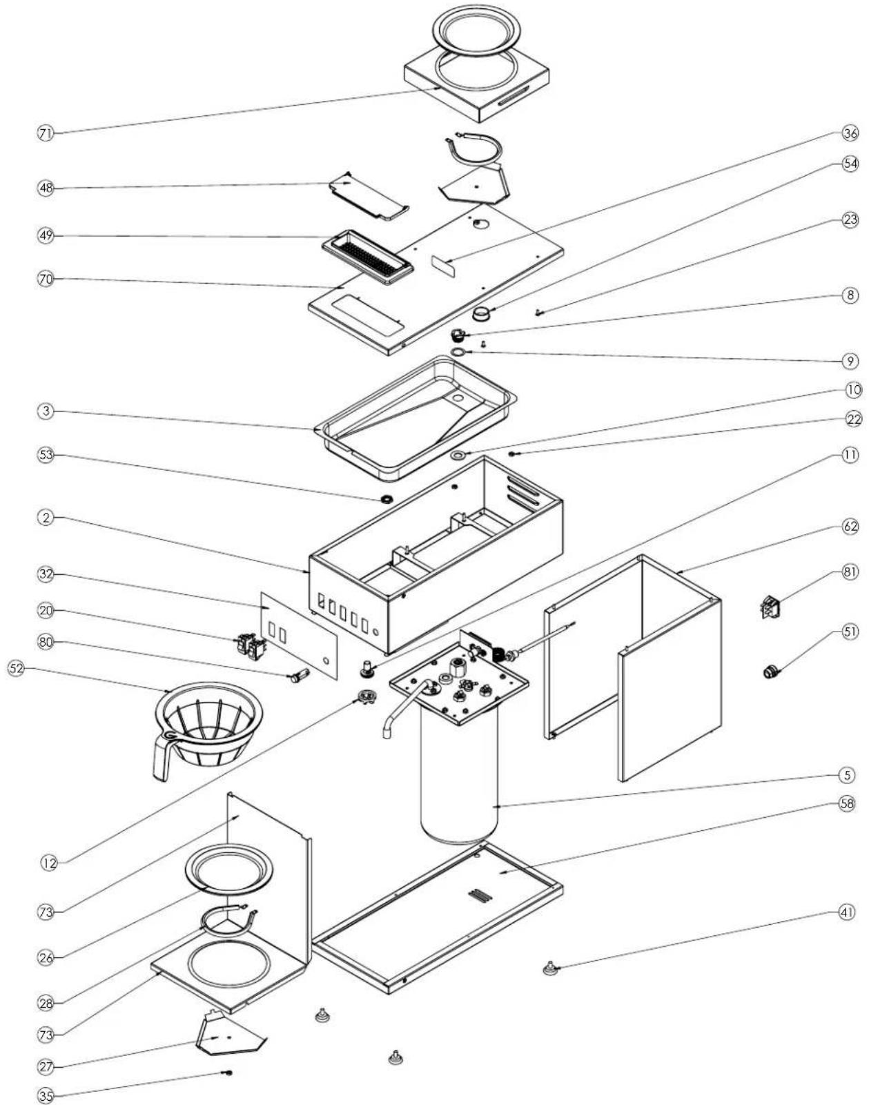
Parts Diagrams and List (continued)
CPO-3P, CPO-3P-E and CPO-3CP,
Refer to Parts List on page 16

Parts Diagrams and List (continued)
CPO-3RP, CPO-3RP-E, and CPO-3RCP
Refer to Parts List on page 16
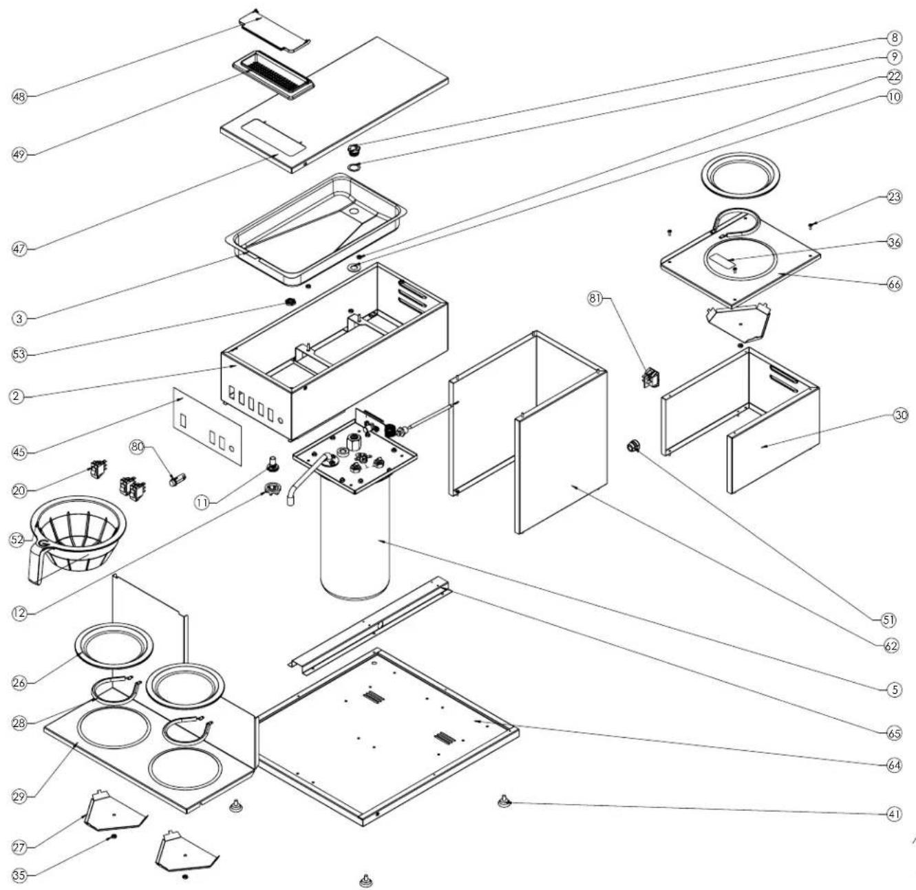
Parts Diagrams and List (continued)
CPO-4RP and CPO-4RP-E
Refer to Parts List on page 16

Parts Diagrams and List (continued)
CPO-5P and CPO-5P-E
Refer to Parts List on page 16
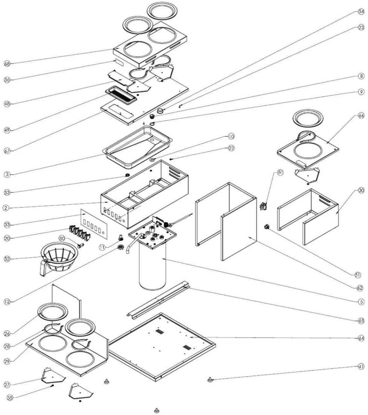
Parts Diagrams and List (continued)
CPO-SAPP and CPO-SAPP-E
Refer to Parts List on page 16

Parts Diagrams and List (continued)
Parts List
| ITEM NO. PART NO. DESCRIPTION ITEM NO. PART NO. DESCRIPTION | ||||
| 2 | 200-00171 | POUROVER TOP WELDMENT | 38 | A320-143 AIR POT STOPPER |
| 3 | 200-00281 | POUROVER PAN CPO | 40 | A71907 PANEL, BASE B-SGP |
| 4 | 200-00150 | BREWER WATER OUTLET PIPE | 41 | 80415 LEG, ADJ NONSKID LEVELER |
| 5 | 200-00157 | POUROVER TANK WELDED | 43 | 380-00225 FRONT LABEL CPO-SAP |
| 6 | 200-00154 | TANK COVER POUROVER ONLY WELD | 44 | 380-00223 FRONT LABEL CPO-4R |
| 7* | 70821 GASKET, WATER TANK | 45 | 380-00222 FRONT LABEL CPO-3R | |
| 8* | 73008 NUT | SLOTTED HEX | 46 | 380-00219 FRONT LABEL CPO-1 |
| 9* | 73009 WASHER 1"OD 3/4"ID SS | 47 | 200-00298 LID CPO-1, CPO-3R Weld | |
| 10* | 73007 GASKET 1.062OD 0.578ID | 48 | 210-00294 LID PLASTIC POUR-OVER | |
| 11* | 06490 NOZZLE, SPRAY HEAD | 49 | 210-00295 MOUNT LID PLASTIC POUR-OVER | |
| 12* | 06491 DEFLECTOR, SPRAY | 50 | 73256 SCR M4-0.7X8 PH TH SS | |
| 13* | 290-00028 | BREW WATER OUTLET GASKET | 51 | 61479 STRAIN RELIEF HEYCO |
| 14* | 321-00020 | THERMOSTAT, 98C-CPO | 52* | 71952 BASKET, BREW, MOLDED |
| 15* (120V) | 70818 ELEMENT, HEATING 1400W | 53* | 07220 NUT, 1/2-20 HX PL | |
| 15* (240V) | 70820 ELEMENT, HEATING 2500W | 54 | 71620 BUSHING, HOLE 1-3/32DIA A511008 | |
| 16* | M461A SEAL SILICONE 12MM - GB/QB | 58 | 71593 PANEL, BASE B-3,B-SAP | |
| 17* | M197A WASHER RED SILICONE (D042A) | 59 | 200-00599 PANEL, CENTER, CPO-SAP | |
| 18 | M245AL KNOB BLACK (L681A) | 60 | A71946 PANEL FRONT WRAP B-SAP | |
| 19 | P033AL NUT, #10-32 X .375 X .130 HX SS | 61 | 07026-07 SCREW, 8-32x3/8 PH PN HD 18-8 S/S | |
| 20* | 73059 SWITCH, WARMER, LIGHTED | 62 | 200-00598 PANEL, CENTER CPO | |
| 21* (120V) | L573AL | HI LIMIT SWITCH | 64 | A71599 PANEL, BASE B-3W |
| 21* (240V) | A536-023 HI LIMIT SWITCH | 65 | A71600 BRACKET, STIFFENER B-3W | |
| 22 | 73261 NUT #8-32 HX SS | 66 | A71609 PANEL, SIDE WARMER TOP B-3W | |
| 23 | P184AL SCREW,6-32X3/8,SS PH TR HD | 67 | 200-00297 LID CPO-3, CPO-5R weld | |
| 24 | 07206-05 NUT 1/2"-20 HX JAM | 68 | 71608 PANEL, 2-WARMER B-3 | |
| 25* | 71155 TUBING, 5/16IDX3/32WL SILICONE | 70 | 200-00296 LID CPO-2, CPO-4 weld | |
| 26* | 71577 PLATE, WARMER, 1-STUD | 71 | 200-00173 PANEL, 1 WARMER | |
| 27* | 71592 BRACKET, WARMER B-3 | 73 | 71602 PANEL, FRONT WRAPPER B-3 | |
| 28* (120V) | 13029 HEATER, WARMER 120V | 74 | 380-00173 DECAL, CAUTION HOT LIQUID | |
| 28* (240V) | A535-028 HEATER, WARMER 100W 240V | 75 | 343-00103 HARNESS, CPO-SERIES | |
| 29 | 71603 PANEL, FRONT WRAPPER,B-3WR | 76* | 343-00104 POWER CORD 15A (120V) | |
| 30 | 71601 PANEL, COLLAR,B-SAP,B-3W | 77* | 343-00105 POWER CORD 14/3 W/NEMA 20A (120V) | |
| 31 | 380-00221 | FRONT LABEL CPO-3 | 76*/77* | 61453 POWER CORD (240V) |
| 32 | 380-00220 | FRONT LABEL CPO-2 | 78 | 354-00006 HEYCO BUSHING, 0.562 HOLE |
| 33 | 380-00224 | FRONT LABEL CPO-5R | 79 | 73096 PROBE CLIP ASSEMBLY |
| 35 | 70322 NUT, 10-32 KEPS SS | 80* | 345-00024 GREEN READY LIGHT | |
| 36 | 380-00171 | DECAL, CAUTION WARMER | 81* | 70449 SWITCH, MAIN POWER |
| 37 | 380-00172 | DECAL, WARNING DISCONNECT POWER | ||
| * available for order as replacement part | ||||
Wiring Diagram
Wiring Diagram
![NOTES: 1) ALL WIRE TO BE 2) TYPE WITH DR. TELK OF ARM COVER 3) 100-DCORDED C RATED 4) 300-VOLT RATED ALL WIRE MUST BE 18 AND UNLESS OTHERWISE SPECIFIED 5) UL & CSA USED & LABELED 2) ALL CONNECTORS TO BL UL & CSA LISTED, C RAP ON, FULLY INSOLATED CONDUCTORS APPLIED TO WIRE WITH MAJENDRUTS DESIGNATED CRAP TOOL, UNLESS SPECIFIED AS SWE. 3) ALL BURGALD OF MIRCS TO FORAN A HARNESS TO BE ACCOMPLESH BY USE OF HYLOW TELS. 4) SUPPLIER TO FURNISH PRODUCTION SAMPLE TO GRIEMSTER ON MANAGER, FOR ANGENTURAL BEFORE APPROVAL TO SHIP PRODUCTION DURATION TO GRIELED. 5) ALL SHIPPING CARTIONS TO BE Labeled PER UL STANDARD #754 6) ALTERNATE: SPACE MAY BE FULLY APPLICATED IN-LINE STYLE OF UL & CSA LISTED COMPONENTS 7) ALL DIMENSIONS ARE IN RIOES AND [TAC] IN BRANCHIT. LOWER LOWER PLATE LT BLUE WHITE 27" [360.6] 14" [360.6] YELLOW TE (779.2) 13" [360.2] FAMTS NO. 243-40193 FAMROSS 12.14C FAM SWITCH ETH BAND MD SWITCH ETH BAND MD SWITCH ETH PURPLE MD SWITCH ETH WHITE MD SWITCH ETH YELLOW MD SWITCH ETH RED MD SWITCH ETH BLACK MD SWITCH ETH WHITE MD SWITCH ETH RED MD SWITCH ETH BLACK MD SWITCH ETH YELLOW MD SWITCH ETH RED MD SWITCH ETH BLACK MD SWITCH ETH YELLOW TO BUDY LIGHT WHITE TOP SWITCH/STRAWTHI TOP SWITCH/STRAWTHI TOP SWITCH/STRAWTHI TOP SWITCH/STRAWTHI TOP SWITCH/STRAWTHI TOP SWITCH/STRAWTHI TOP SWITCH/STRAWTHI TOP SWITCH/STRAWTHI TOP SWITCH/STRAWTHI TOP SWITCH/STRAWTHI TOP SWITCH/STRAWTHI TOP SWITCH/STRAWTHI TOP SWITCH/STRAWTHI TOP SWITCH/TAB BLUE TE PN0-100143-5 TOP SWITCH/TAB BLUE TE PN0-100143-5 TOP SWITCH/TAB BLUE TE PN0-100143-5 TOP SWITCH/TAB BLUE TE PN0-100143-5 TOP SWITCH/TAB BLUE TE PN0-100143-5 TOP SWITCH/TAB BLUE TE PN0-100143-5 TOP SWITCH/TAB BLUE TE PN0- TOP SWITCH/TAB RED TE PN 160824-3 TOP SWITCH/TAB RED TE PN 160824-3 TOP SWITCH/TAB RED TE PN 160824-3 TOP SWITCH/TAB RED TE PN 160824-3 TOP SWITCH/TAB RED TE PN 160824-3 TO BUDY LIGHT WHITE TO BUDY LIGHT RED TO BUDY LIGHT GREEN TAKE HEATER TANK HEATER TANK HEATER TANK HEATER TANK HEATER TANK HEATER TANK HEATER TANK HEATER TANK HEATER TANK HEATER TANK HEATER TANK HEATER TANK HEATER TANK HEATER TANK HEATER TANK HEATER TANK HEATER TANK HEATER TANK HEATER TANK HEATER TANK HEATER TANKE HENDER TANK HENDER TANK HENDER TANK HENDER TANK HENDER TANK HENDER TANK HENDER TANK HENDER TANK HENDER TANK HENDER TANK HENDER TANK HENDER TANK HENDER TANK HENDER TANK HENDER TANK HENDER TANK HENDER TANK HENDER TANK HENDER TANK HENDER TANK HENDER TANKE HENDER TANKE HENDER TANKE HENDER TANKE HENDER TANKE HENDER TANKE HENDER TANKE HENDER TANKE HENDER TANKE HENDER TANKE HENDER TANKE HENDER TANKE HENDER TANKE HENDER TANKE HENDER TANKE HENDER TANKE HENDER TANKE HENDER THERMOSTAT IN WIRE LEGEND: NUMBER AND COUP VOLTAGE QTY LENGTH: 1 2 3 4 5 6 7 8 9 10 11 12 13 14 15 16 17 18 19 20 21 22 23 24 25 26 27 28 29 30 31 32 33 34 35 36 37 38 39 40 41 42 43 44 45 46 47 48 49 50 51 52 53 54 55 56 57 58 59 60 61 62 63 64 65 66 67 68 69 70 71 72 73 74 75 76 77 TERMINAL LEGEND: A = WIRE TERMINAL 14-18-AWS BLUE TE PN0-058819 B = PDC/SHACK RDT/TAB BLUE TE PN0-100143-5 C = FLNG TERM ZND BLUE TE PN 3-830133-2 D = FASTON ZND BLUE TE PN 3-830146-3 E = FASTON ZND RED TE PN 3-830147-3 F = WIRE SPACE BLUE TE PN 14-18 MW TE PN 3-830148-3 G = PDC/SHACK RDT/TAB RED TE PN 160824-3 H = FASTON ZND YELLOW TE PN-5-MAG TE PN 4-830147-3 I = PLUG HOSEAWA, P POSITION MOLDY DZ-06-2052 J = CONV TERMINAL P/V, 18-24 MW HOLDX DZ-06-5103 K = RECEPTACLE HOSEAWA, P POSITION VOLZEN DZ-06-1052 L = CONV TERMINAL RECEPT LEANS MOLDY DZ-06-5103](/content/2026/05/935334/images/35ce88a713dec11f98f95d8d0253330e0624ebfcd652be4e41d793a218512a46.jpg)
GMCW
4003 Collins Lane, Louisville, KY 40245 USA
Phone: 502.425.4776 Toll Free: 800.695.4500
Fax: 502.425.4664
Web: gmcw.com Email: info@gmcw.com
©2015 GMCW
Printed in USA

GMCW™
0715 Form # BW-328-01
Part # 390-00038


- Portable Pourover Coffee Brewers
- Table of Contents
- GMCW
- Safety Information
- Important Safety Information
- WARNING
- CAUTION
- NOTICE
- General Information
- Installation
- Operation
- Coffee Preparation Procedures
- Operation (continued)
- Cleaning & Maintenance
- Cleaning Instructions
- After Each Brew:
- Every Day:
- Sanitizing:
- Maintenance
- Draining Water Tank
- Cleaning & Maintenance (continued)
- Descaling the coffee brewer
- ⚠ WARNING Disconnect power before servicing.
- Component Replacement Instructions
- These steps apply to replacement of TANK, TANK HEATER, and HI-LIMIT or MAIN THERMOSTAT
- THERMOSTAT, HI-LIMIT
- MAIN THERMOSTAT
- TANK HEATING ELEMENT
- WARMER ELEMENT
- Troubleshooting Guide
- Parts Diagram and List
- Water Tank Assembly - all models
- Parts Diagram and List (continued)
- Parts Diagrams and List (continued)
- CPO-5P and CPO-5P-E
- Wiring Diagram
Brand : Cecilware
Model : CPO-SAPP
Category : Coffee maker