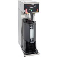
PrecisionBrew Digital B-SGP - Coffee maker Cecilware - Free user manual and instructions
Find the device manual for free PrecisionBrew Digital B-SGP Cecilware in PDF.


| Product Type | Commercial Coffee Brewer |
| Brand | Cecilware |
| Model | PrecisionBrew Digital B-SGP |
| Dimensions (W x D x H) | 17.5 x 20.0 x 28.0 inches |
| Weight | 52 lbs |
| Power Supply | 230V / 60Hz, 3000W |
| Brewing Capacity | Dual 1.5-gallon insulated servers |
| Control Type | Digital programmable timer and brew selector |
| Brewing Modes | Single or dual batch, manual or timed |
| Water Supply | Direct plumbed with optional water filter |
| Material | Stainless steel body and warming plates |
| Safety Features | Automatic shut-off, overheat protection, brew basket interlock |
| Cleaning | Removable brew basket and spray head; daily rinse and periodic descaling |
| Spare Parts Availability | Brew baskets, decanters, heating elements, control boards |
| Repairability | Modular design with accessible components; service manual available |
| Certifications | UL, NSF, ETL |
Frequently Asked Questions - PrecisionBrew Digital B-SGP Cecilware
User questions about PrecisionBrew Digital B-SGP Cecilware
0 question about this device. Answer the ones you know or ask your own.
Ask a new question about this device
Download the instructions for your Coffee maker in PDF format for free! Find your manual PrecisionBrew Digital B-SGP - Cecilware and take your electronic device back in hand. On this page are published all the documents necessary for the use of your device. PrecisionBrew Digital B-SGP by Cecilware.
USER MANUAL PrecisionBrew Digital B-SGP Cecilware
The National Sanitation Foundation requires the following for an NSF approved water hook-up:
- A quick disconnect water connection or enough coiled tubing so that the machine can be moved for cleaning underneath.
- An approved backflow prevention device, such as a double check valve to be installed between the machine and water supply.
A 1/4" male flare adapter is provided. Installation to a water filter system is recommended to prevent lime and scale build-up in the machine.
• Water pipe connections and fixtures directly connected to portable water supply shall be sized, installed and maintained in accordance with
federal, state and local codes.
- Flush the water line to purge any debris from the supply line.
Connect a 1/4" pressurized water line to the 1/4" male connection (on rear of brewer) and turn the water supply on.
a) Minimum water pressure to the machine: 30 psi
b) Maximum water pressure to the machine: 80 psi
NOTE: Single head machines may be used without a pressurized water supply. (See Pour-Over Mode section)
ELECTRICAL CONNECTION
NOTE: Wiring connections should be performed by a qualified technician. (Refer to serial tag to verify model number of your machine)
- Remove front panel.
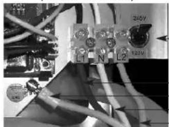
- Connect electrical service through rear of machine to terminal block (inside front panel) marked L1, N, and L2. (See Figures A and B)
- On dual volt units, flip voltage switch (inside front panel next to terminal block) to 120V for 120 Volt service or 240V for 120/208, or 120/240 Volt service. (See Figures A, B and table below)
- Re-install front panel.
- Turn on (plug-in) electrical service to brewer.
• Water tank will fill after a 7-second delay. The machine will make a hissing sound when this occurs. On single head models, allow
approximately 1.5 minutes for the brewer to fill. On two head models, allow approximately five minutes for the brewer to fill.
For 120V, 15A or 20A Service (2 Wire + Ground)

natural_image
Close-up of electrical wiring and components with no visible text or symbolsON DUAL VOLT UNITS, FLIP SWITCH TO "120V"
CONNECT NEUTRAL (N) TO MIDDLE
CONNECT HOT (L1) TO LEFT SIDE
CONNECT GROUND TO SCREW
For 120/208-240V, 20A Service (3 Wire + Ground)
natural_image
Close-up of an electrical circuit board with wires and components (no readable text or symbols)ON DUAL VOLT UNITS,
FLIP SWITCH TO "240V"
CONNECT HOT (L1) TO LEFT SIDE
CONNECT GROUND TO SCREW
CONNECT NEUTRAL (N) TO MIDDLE
CONNECT HOT (L2) TO RIGHT SIDE
Figure B
NOTE: If water supply is inadequate or not connected, display will read "P-O" after 4 minutes of fill time (Refer to Pour-Over Mode section). If Fill Cycle times out and display reads "P-O" before tank is full, turn unit OFF then ON again to reset and continue filling.
• The tank will begin heating slightly before machine fills.
- Turn brewer on by pressing ON/OFF switch in front of machine. (Light will illuminate)
- The brewer settings can be adjusted through the front touch pad. (Refer to Adjustments section)
- The water will be hot and the brewer will be ready to brew when "READY" light illuminates.
- Set Brew volume. (Refer to Setting Brew Volume section)
POWER REQUIREMENTS: (Refer to serial tag for voltage to be supplied.)
| Applied Volts | Models | Watts | Amps | NEMA Plug | Cord AWG | Connections |
| 120 | B-3, B-3WL, B-3WR 1800 15 | 5-15P, 5-20P for CUL | 3X14 | Hot to L1Neutral to NGround to ground screw | ||
| B-SAP, B-ID | 1780 | 14.9 | ||||
| 120/208 | B-3, B-3WL, B-3WR 2920 | 14.1 | L14-20P | 4X12 | Hot to L1Neutral to NHot to L2Ground to ground screw | |
| B-SAP, B-ID, B-DAP, B-DGP | 2620 | 12.6 | ||||
| B-6 | 5110 | 24.6 | L14-30P | 4X10 | ||
| B-DAP, B-DGP (30A) | 4510 | 21.7 | ||||
| 120/240 | B-3, B-3WL, B-3WR | 3800 | 15.9 | L14-20P | 4X12 | Hot to L1Neutral to NHot to L2Ground to ground screw |
| B-SAP, B-ID, B-DAP, B-DGP | 3500 | 14.6 | ||||
| B-6 | 6600 | 27.5 | L14-30P | 4X10 | ||
| B-DAP, B-DGP (30A) | 6000 25 |
Page 2 B-SERIES
FACTORY SETTINGS (for each dispense head)
- Tank temperature is set at 200 degrees F.
- Brew time is pre-set at 2:20. (Volume/time to be set on-site)
- Pulse Brew is set for 1 pulse, 20 sec on, 20 sec off.
- Warmer Energy Savings mode is set for 60-minutes. ("OFF" for models without warmers)
- Low Temp / No Brew option is set to "OFF" or disabled.
- Pour over setting override is set to "no" or plumb in.
- Settings lock-out jumper on controller is set in "unlock" position.
ADJUSTMENTS:
Refer to B-Series Programming Chart on page 5.
NOTE: Set each dispense head individually on two head models with two controllers and serial numbers A166225 and lower (without a -P suffix). Tank temperature must be set to the same setting on both heads in order for the unit to operate properly.
Tank Temperature:
Left display controls this.
- Press-and-hold both "up" and "down" arrows for 5 seconds.
- The display will indicate either "d F" or "d C". (Fahrenheit or Celsius)
- Press up or down arrow to change from one scale to the other.
- Press "BREW" button to accept and proceed to the next setting.
- The display will read temperature value in the scale previously selected.
- Press up or down arrow to change temperature value.
- Press "BREW" button to accept and proceed to the next setting.
Brew Time:
- The display will read "br". (brew time)
- Press "BREW" button to proceed to the next setting.
- The display will read the set brew time in minutes and seconds. (ex: 2.20)
- Press up or down arrow to change time value.
- Press "BREW" button to accept and proceed to the next setting.
Pulse Brewing Mode:
- The display will read "P-b". (pulse brew)
- Press "BREW" button to proceed to the next setting.
- The display will read "OFF" - "1"- "6".
- Press up or down arrow to change number of pulses.
- Press "BREW" button to proceed to the next setting.
• The display will read "0.05" - "0.30". - Press up or down arrow to change pulse-on time for each pulse in seconds.
- Press "BREW" button to proceed to next setting.
- The display will read "0.05" - "0.30".
- Press up or down arrow to change pulse-off time for each pulse.
- Press "BREW" button to accept and proceed to the next setting.
Energy Savings Mode (Warmer shut-off):
- The display will read "E-S". (energy savings)
- Press "BREW" button to proceed to the next setting.
- The display will read "Off" - "10" - "240" in multiples of 10.
- Press up or down arrow to change time value in minutes. Must be "OFF" for models without warmers.
- Press "BREW" button to accept and proceed to the next setting.
Low Temp/No Brew Mode:
- The display will read "Ltn" (Low Temp/No Brew).
- Press "BREW" button to proceed to the next setting.
- Press up or down arrow to change to "ON" or "OFF".
- Press "BREW" to accept and proceed to the next setting.
B-SERIES Page 3
ADJUSTMENTS (cont.):
Refer to B-Series Programming Chart on page 5.
Pour-Over Mode
Left display controls this.
- The display will read "P-O" (pour-over).
- Press "BREW" button to proceed to the next setting.
- Press up or down arrow to change to "YES" or "NO". Plumbed-in units must be set to "NO".
- Press "BREW" button to accept and exit menu.
SETTING BREW VOLUME:
- Remove brew basket & spray head.
- Make sure "READY" light is on.
- Place empty server under exit nozzle to capture water.
- Press "BREW" button to fill water lines.
- Press "BREW" button again after approximately 10 seconds to stop water flow.
- Empty server then place under exit nozzle.
- Press-and-hold "BREW" button for 5 seconds until display reads "Pro", then release.
- Press-and-release "BREW" button to initiate brew.
- The brew valve opens and the time begins to count up on display.
• Water will flow into decanter. - When water level reaches desired amount, press-and-release "BREW" button again.
• Time value will flash in the display. - Press-and-release "BREW" button within 10 seconds to set time.
- Reinstall spray head and brew basket.
- Repeat process for each brew head.
BREWING PROCEDURE:
- Place a new paper filter in the brew basket.
- Put desired amount of ground coffee in brew basket. (3.5 oz (100 grams) maximum)
- Place decanter or airport under brew basket.
- Be sure lower warmer is on. (if available)
- Press "BREW" button to start brewing.
The "READY" light will flash for the entire brew cycle.
Water will dispense for the set time of brew, and light will flash after water is dispensed to denote "drip time".
(ex.. Time set for 2:30, water is dispensed for 2:30, and light continues to flash for another 1:15 for total brew cycle of 3:45.)
Do not remove the brew basket while the "READY" light is blinking.
A stop function is added to the "BREW" switch. Pressing the "BREW" switch during a brew cycle will stop the brew. Coffee will need to be emptied from brew basket and brew procedure will need to be started again.
After a brew cycle, the tank must reheat and the "READY" light must be lit before starting the next cycle. Reheat (recovery) time is dependent on voltage applied and inlet water temperature.
Approximate reheat times for a 64 oz decanter are as follows:
120 Volt supply: 3-4 minutes; 120/208 Volt supply: 30-90 seconds; 120/240 Volt supply: 0 - 30 seconds
PULSE BREWING MODE:
- When mode is “ON” (number of pulses, pulse on, and pulse off time), and a brew cycle is initiated, water is dispensed for the ON time then stops for the OFF time to define one pulse. This repeats for number of pulses programmed. After pulsing is finished, the water continues to dispense for the remaining set time. During the pulse-off time, the water infuses the coffee and the bed rises to allow for better extraction.
- When mode is "OFF" and a brew cycle is initiated, water is dispensed continually for the entire set time without any delay.
ENERGY SAVINGS MODE (WARMER SHUT-OFF):
(ONLY FOR MODELS WITH WARMERS)
When set time has elapsed after a brew cycle, the lights above the warmer switches will flash and the warmers will automatically turn off. To stop lights from flashing, press one of the warmer switches. To turn warmers back on, press corresponding warmer switch. The timer will reset when a new brew cycle is initiated.
Refer to Adjustments section to adjust time values or simply disable mode. Time values may be adjusted from OFF to 10 minutes to 240 minutes in increments of 10 minutes.
Page 4 B-SERIES
LOW TEMP/NO BREW MODE:
When set to "ON", a brew cycle cannot be initiated until tank is hot and "READY" light is ON. When set to "OFF", a brew cycle may be initiated at any time.
POUR-OVER MODE:
Note: Not available on B-6, B-DAP, and B-DGP (twin) models.
Brewers are capable of operating without a pressurized water source.
If there is no pressurized water source, brewer can be set-up as a pour-over.
- If no water is in the tank to begin with, pour about three decanters of fresh water into the basin (Fig. D). A small amount of water should remain in the basin.
- If tank already has water, pour fresh water into basin (Fig D) until a small amount is in the basin and no longer drains into the tank.
- Place server under the EMPTY brew basket.
- Turn power on to machine
- Go into Settings Mode and change "P-O" to "YES".
- Display will read "P-O". (Fig C)
- Wait until Ready light illuminates.
- Press-and-release Brew button to initiate a brew cycle.
- Water should stop flowing before READY light stops flashing to create a "short pot".
- After tank water recovers and READY light illuminates, brewer is ready to brew coffee. See Brew Procedure.

Figure C
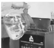
Figure D
If brewer is in operation (connected to a pressurized water source) and water is shut off for four minutes, display will read "P-O" (Fig C) and brewer can be used as a pour-over;
- Place server under the EMPTY brew basket.
- Wait until Ready light illuminates.
- Press-and-release Brew button to initiate a brew cycle.
- Water should stop flowing before READY light stops flashing to create a "short pot".
- After tank water recovers and READY light illuminates, brewer is ready to brew coffee. See Brew Procedure.
If water pressure problem is resolved, simply press Off then On.
Brew Procedure while brewer is in pour over "P-O" mode:
- Wait until tank water heats up and READY light is on.
- Place brew basket in place with ground coffee inside filter.
- Pour a full (64oz) maximum container of fresh water into basin at top/front of brewer. (Fig D)
- Place container under brew basket.
- Press-and-release "BREW" button to initiate brew cycle.
COUNTER:
The brewer is equipped with a counter that displays the total number of brew cycles for each dispense head. After turning the brewer on, the number will scroll across the display two times and then clears.
CLEANING CABINET
- The outside of the brewer can be cleaned with a damp cloth, a household dusting spray or a stainless steel cleaner. Do not use an abrasive such as Scotchbrite or Brillo pads. These may mar the finish.
- Wipe the underside of the cabinet hood with a clean cloth. Be especially careful when using soap or detergent around the sprayhead. Any soap left on the deflector may impart an unpleasant taste to the first brews.
CLEANING WARMERS
The warmer plates are easy to clean and will maintain its appearance longer if cleaned regularly. Coffee stains can be wiped off with a damp cloth. Use detergent or sanitizer for heavy deposits, but refrain from using abrasives.
CLEANING BREW BASKET, AIRPOTS AND DECANTERS
Use commercial grade urn cleaner (as directed by manufacturer) and rinse thoroughly.
B-SERIES Page 5
User Lockout
User Lockout is achieved via the position of the LOCK jumper on the board header. Locate the header on the board (shown below) and place the jumper in the desired position. In the Locked position all menus in this document are locked out, and the unit will only allow brewing or grinding functions. There are two versions of the header, 10 pin and 2 pin. Both configurations are shown below.

User Lockout Jumper
Controller Fuse Sizes
Fuses
Controller (pn A530-059) uses (2) 5mm x 20mm 5 Ampere fuses.
Controller (pn A530-056) uses (2) fuses - 1.25" x 0.25" 3AG series 312.
- (1) is a 1 Ampere 3AG-1
- (1) is a 5 Ampere 3AG-5
Programming for B-Series
| DISPLAY READING | ADJUST | ADVANCE | |||
| TEMP SCALE |  | OR |  | △▽ |  |
| TANK TEMP (170-202F) | 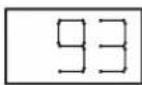 | OR |  | △▽ |  |
| BI |  |  | |||
| BREW TIME |  | △▽ |  | ||
| PUI |  |  | |||
| # OF PULSES (OFF, 1 - 6) | 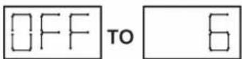 | △▽ |  | ||
| PULSE ON TIM |  | △▽ |  | ||
| PULSE OFF TII |  | △▽ |  | ||
| ENER (WARME) | 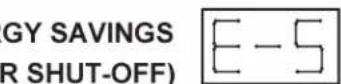 |  | |||
| SHUT-OFF TIME (OFF, 10-240 MINUTES) | 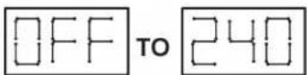 | △▽ |  | ||
| LOW-TEM |  |  | |||
| LOW-TEMP/ NO-BREW |  | △▽ |  | ||
| POUR- |  |  | |||
| POUR-OVER MODE |  | △▽ |  | ||
Models B-3, B-3WR, B-3WL, B-SAP & B-ID Parts List
serial numbers without a -P suffix only
Model B-3 Dual Voltage Unit Shown

* Each kit includes: (1) A530-056 controller and (1) A71933 touchpad
A71577
Warmer Plate
(not shown)
Models B-3, B-3WR, B-3WL, B-SAP & B-ID Parts List
serial numbers with a -P suffix only
Model B-3 Dual Voltage Unit Shown

Models B-3, B-3WR, B-3WL, B-SAP & B-ID Parts List
Dual Voltage Unit Shown
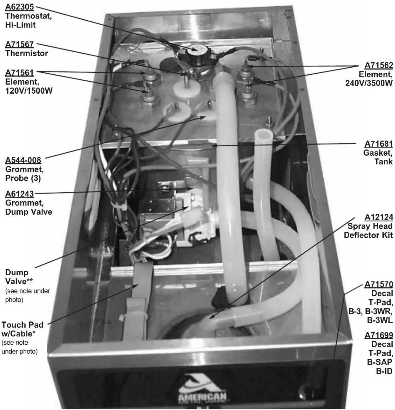
Touch Pad w/ Cable:
* A71933: used on serial numbers without a -P suffix and with controller # A530-056
A530-061: used on serial numbers with a -P suffix and with controller # A530-059
Dump Valve:
** A71684 (24VAC): used on serial numbers without a -P suffix and with controller # A530-056
A64062 (24VDC): used on serial numbers with a -P suffix and with controller # A530-059
Models B-6, B-DGP & B-DAP Parts List
serial numbers without a -P suffix only
Model B-6 Shown
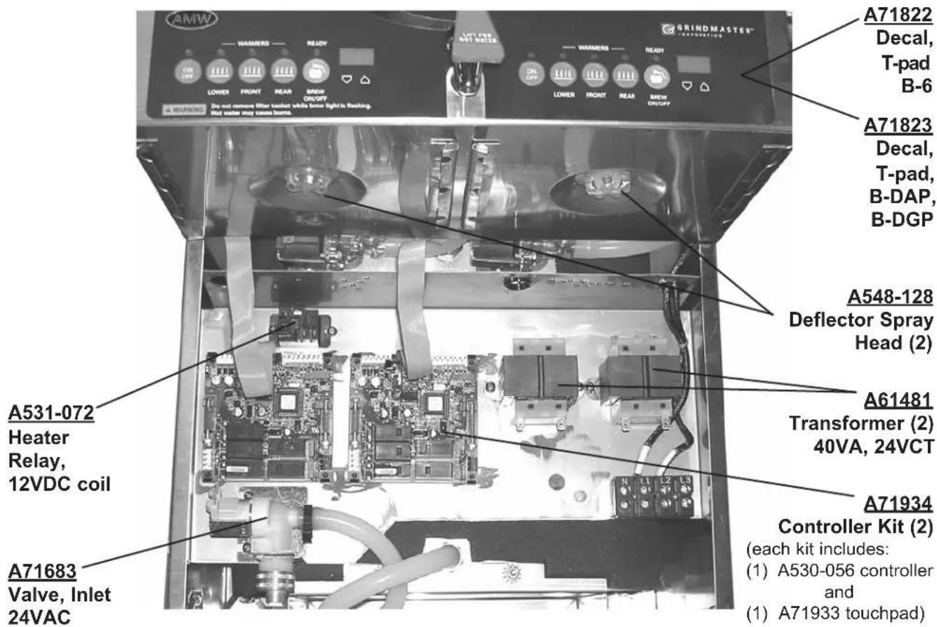
A71619
Brew Basket Assy. (not shown) (2)
A13029
Warmer Heater (not shown)
A71577
Warmer Plate (not shown)
A71431
Gourmet Brew Basket Assy (optional for B-DAP, B-DGP) (not shown)
Models B-6, B-DGP & B-DAP Parts List
with a -P suffix only
Model B-6 Shown

A71619
Brew Basket Assy. (not shown) (2)
A13029
Warmer Heater (not shown)
A71577
Warmer Plate (not shown)
A71431
Gourmet Brew Basket Assy (optional for B-DAP, B-DGP) (not shown)
Models B-6, B-DGP & B-DAP Parts List

Thermistor:
NOTE 1: (2) Thermistors (pn A71567) used on serial numbers without a -P suffix only and with controller # A530-056.
(1) Thermistor (pn A71567) used on serial numbers with a -P suffix only with controller # A530-059.
Dump Valve:
NOTE 2: A71684 (24VAC): used on serial numbers without a -P suffix and with controller # A530-056.
A64062 (24VDC): used on serial numbers with a -P suffix and with controller # A530-059.
Touch Pad w/ Cable:
NOTE 3: A71933: used on serial numbers without a -P suffix and with controller # A530-056.
A530-061: used on serial numbers with a -P suffix only and with controller # A530-059.
B-SERIES Page 13
| TROUBLESHOOTING GUIDE | ||
| Problem | Possible Cause | Solution |
| Weak coffee | Not enough coffee usedGrind is too coarseWater not hot enoughCoffee bed has dry areas | Set to portion more coffeeReadjust to finer grindCheck spray temp; should be greater than 185°F/85°C Spray deflector broken or missing. Replace |
| Strong coffee | Too much coffee used | Use less coffee |
| Bitter coffee | Grind is too fine | Use a coarser grind |
| Grounds in coffee | Paper filter collapsed during brewing | Use proper filterPosition filter carefully |
| Brew basket overflowed | Too much coffeeGrind is too fineDouble batching | Use no more than 3 1/2 oz. (100 grams) of coffeeUse a coarser grindYou must dump old coffee and use fresh new filter for each brew |
| Unpleasant taste | Water tank or brew basket needs cleaning | Clean, sanitize (delime) |
| Quantity of coffee dispensed each throw is not the same | Lime scale build-upHose kinkedDump Valve not adjusted properlyDefective timer | Delime machineCheck hosesTurn screw on Dump Valve to open fullyCheck the length of time brewer runs with watch |
| Circuit breaker trips continuously | Insufficient current due to use of extension cordInsufficient current due to overloaded line | Plug unit directly into outlet. Do not use extension cordDesignate single line for unit. Do not use multi-outlet box |
| Control board displays “P-O” | Water supply turned offWater fill valve on too long | Turn water supply on, then reset powerClean or replace water fill valve |
| Control board displays “ER2” | Problem with thermistor | Replace if defective |
| Water boiling (or steaming) | Temperature set too highDefective thermistor | Check settings with actual temperature |
| No lights are on (including warmer lights) | No power to brewerPower switch turned offTouch pad disconnected | Check power at sourceTurn switch onReconnect touchpad |
| Too much or not enough water in server | Water volume adjustment | Readjust |
| Spray head dripping | Lime build up in dump valve | Delime unit |
| Hot water spigot dripping | Faulty seal | Replace seal |
| Hot water spigot not dispensing | Tube limed upDefective valve seat | Delime tankReplace seat |
| Warmer failure | Loss of powerBus fuse (5 Amp) on controller board is blownDefective warmer heater | Check power sourceReplace fuseReplace defective heater |
| Water solenoids not working | Bus fuse (1 Amp) on controller board is blown | Replace fuse |
| One indicator light will not illuminate | LED burned out | Replace touchpad |
| Error MessagesProblem Possible Causes Service Check Remedy | |||
| ER1 | Fill valve on for over 6 min. (This occurs during initial fill on some units – see Initial Start-up.) | Check system for water leaks. | Correct any leaks and reset controller. |
| ER2 | Thermistor failure or loose connections in thermistor circuit. | Ensure that connector is securely attached to controller and that thermistor is securely connected. | Secure connections and reset controller. If error reoccurs, replace thermistor. |
| ER3 | Thermistor is reading out of range. | Check tank temperature. | Replace thermistor. |
| ER4 | No heating is detectedVerify power to heating element and high limit operation | Repair as needed. | |
If you still need help, call an authorized dealer in your area or our Technical Service Department. You can reach Grindmaster Corporation's Technical Service Department at 800-695-4500 (USA & Canada only) or 502-425-4776 Monday-Friday, 8:00 AM - 6:00 PM EST. Please have the model and serial number ready so that accurate information can be given.
Prior authorization must be obtained from Grindmaster Corporation's Technical Services Department for all warranty claims.
Wiring Diagram
Models B-3, B-3WR, B-3WL, B-SAP & B-ID
without a -P suffix
DUAL VOLTAGE
| MODELS: | B-3, B-3WR, B-3WL | B-SAP, B-ID, B-SGP | ||
| WIRES: | 2 + GND | 3 + GND | 2 + GND | 3 + GND |
| VOLTAGE: | 120 | 120/208 -240 | 120 | 120/208 -240 |
| AMPERAGE: | 15 | 14.1/15.9 | 12.5 | 12.6/14.6 |
| WATTAGE: | 1800 | 2928/3800 | 1500 | 2620/3500 |
| TANK HEATER: | 120V/1500W | 240V/3500W | 120V/1780W | 240V/3500W |
| HOOK-UP: | L1, N, GND | L1, N, L2, GND | L1, N, GND | L1, N, L2, GND |
| NEMA PLUG: | 5-15P UL5-20P CUL | L4-12P | 5-15P | L4-12P |
| AWG CORD: | 3 x 14 | 4 x 12 | 3 x 14 | 4 x 12 |
Wiring Diagram
Models B-3, B-3WR, B-3WL, B-SAP & B-ID
without a -P suffix


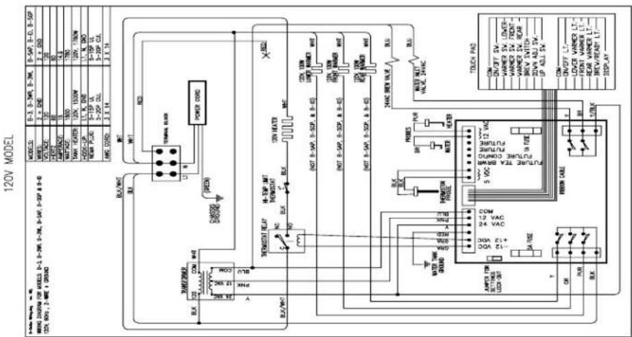
Wiring Diagram Models B-6, B-DAP, B-DGP without a -P suffix
TWIN HEAD B-SERIES BREWER 120/240V, 30A

Wiring Diagram - E Models
Models B-6, B-DAP, B-DGP
without a -P suffix
DOUBLE WIDE BREWER E

Wiring Diagram
Models B-3, B-3WR, B-3WL, B-SAP & B-ID
with a -P suffix only
DUAL VOLTAGE
| MODELS: | B-3, B-3WR, B-3WL | B-SAP, B-ID, B-SGP | ||
| WIRES: | 2 + GND | 3 + GND | 2 + GND | 3 + GND |
| VOLTAGE: | 120 | 120/208 -240 | 120 | 120/208 -240 |
| AMPERAGE: | 15 | 14.1/15.9 | 12.5 | 12.6/14.6 |
| WATTAGE: | 1800 | 2928/3800 | 1500 | 2620/3500 |
| TANK HEATER: | 120V/1500W | 240V/3500W | 120V/1780W | 240V/3500W |
| HOOK-UP: | L1, N, GND | L1, N, L2, GND | L1, N, GND | L1, N, L2, GND |
| NEMA PLUG: | 5-15P UL5-20P CUL | L4-12P | 5-15P | L4-12P |
| AWG CORD: | 3 X 14 | 4 X 12 | 3 X 14 | 4 X 12 |
Wiring Diagram
Models B-3, B-3WR, B-3WL, B-SAP & B-ID
with a -P suffix only


Wiring Diagram Models B-6, B-DAP, & B-DGP with a -P suffix only
TWIN HEAD B-SERIES BREWER 120/240V, 30A

Wiring Diagram - E Models
Models B-6, B-DAP, & B-DGP
with a -P suffix only
DOUBLE WIDE BREWER E


GRINDMASTER™
CORPORATION
Grindmaster® Coffee Grinders and Brewers • PrecisionBrew™ Brewing Systems • Espressimo® Espresso Machines Crathco® Hot Beverage Dispensers • Crathco® Cold and Frozen Beverage Dispensers • AMW Coffee and Tea Systems Tel (502) 425-4776 • Fax (502) 425-4664 • 1-800-695-4500 (USA & Canada only)
P.O. Box 35020 • Louisville, KY 40232 • USA


- ELECTRICAL CONNECTION
- Page 2 B-SERIES
- FACTORY SETTINGS (for each dispense head)
- ADJUSTMENTS:
- Tank Temperature:
- Brew Time:
- Pulse Brewing Mode:
- Energy Savings Mode (Warmer shut-off):
- Low Temp/No Brew Mode:
- B-SERIES Page 3
- ADJUSTMENTS (cont.):
- Pour-Over Mode
- SETTING BREW VOLUME:
- BREWING PROCEDURE:
- Page 4 B-SERIES
- POUR-OVER MODE:
- COUNTER:
- CLEANING CABINET
- CLEANING WARMERS
- CLEANING BREW BASKET, AIRPOTS AND DECANTERS
- B-SERIES Page 5
- User Lockout
- Controller Fuse Sizes
- Fuses
- Models B-3, B-3WR, B-3WL, B-SAP & B-ID Parts List
- serial numbers without a -P suffix only
- Models B-6, B-DGP & B-DAP Parts List
- A71619
- A13029
- A71577
- A71431
- Thermistor:
- Dump Valve:
- Touch Pad w/ Cable:
- Wiring Diagram
- Models B-3, B-3WR, B-3WL, B-SAP & B-ID
- Wiring Diagram Models B-6, B-DAP, B-DGP without a -P suffix
- Wiring Diagram - E Models
- Models B-6, B-DAP, B-DGP
- with a -P suffix only
- Wiring Diagram Models B-6, B-DAP, & B-DGP with a -P suffix only
- Models B-6, B-DAP, & B-DGP
- GRINDMASTER™
Brand : Cecilware
Model : PrecisionBrew Digital B-SGP
Category : Coffee maker