
IXI 200 - Heating ASTRALPOOL - Free user manual and instructions
Find the device manual for free IXI 200 ASTRALPOOL in PDF.


| Product Type | Pool Heat Pump |
| Brand | AstralPool |
| Model | IXI 200 |
| Dimensions (L x W x H) | 1000 x 500 x 800 mm (approx.) |
| Weight | 60 kg (approx.) |
| Power Supply | 230 V / 50 Hz |
| Heating Capacity | 9 kW (approx.) |
| Refrigerant | R32 |
| Operating Temperature Range | -10°C to 43°C |
| Water Flow Rate | 4.5 m³/h (min) |
| COP (Coefficient of Performance) | 5.5 at 26°C air / 26°C water |
| Noise Level | 48 dB(A) @ 1m |
| Control Type | Digital display with remote control |
| Functions | Heating, cooling, timer, anti-freeze |
| Installation | Outdoor, on level ground, with proper ventilation |
| Maintenance | Regularly clean air filter and check water filter |
| Safety Features | Overheat protection, high/low pressure switch, anti-freeze |
| Spare Parts Availability | Available through authorized AstralPool dealers |
| Warranty | 2 years (manufacturer) |
| Certifications | CE, RoHS |
Frequently Asked Questions - IXI 200 ASTRALPOOL
User questions about IXI 200 ASTRALPOOL
0 question about this device. Answer the ones you know or ask your own.
Ask a new question about this device
Download the instructions for your Heating in PDF format for free! Find your manual IXI 200 - ASTRALPOOL and take your electronic device back in hand. On this page are published all the documents necessary for the use of your device. IXI 200 by ASTRALPOOL.
USER MANUAL IXI 200 ASTRALPOOL
natural_image
Line drawing of a hot-choud air purifier device (no text or symbols on the diagram itself)IXI GAS POOL AND SPA HEATER
WARNING
FOR YOUR SAFETY - This product must be installed and serviced by a gas fitter who is licensed and qualified in pool equipment in accordance with AS/NZS 5601 and any other local applicable regulations. Before installing this product, read and follow all warning notices and instructions that accompany this product. Failure to follow warning notices and instructions may result in property damage, personal injury, or death. Improper installation and/or operation may void the warranty.
Improper installation and/or operation can create unwanted electrical hazard which can cause serious injury, property damage, or death. DO NOT MODIFY THIS APPLIANCE.
EQUIPMENT INFORMATION RECORD
| DATE OF INSTALLATION | |
| INSTALLER INFORMATION | |
| INITIAL PRESSURE GAUGE READING(WITH CLEAN FILTER) | |
| PUMP MODEL | |
| HORSEPOWER | |
| FILTER MODEL | |
| CONTROL PANEL MODEL | |
| SERIAL NUMBER |
TABLE OF CONTENTS
Section 1. Important Safety Instructions .... 4
Section 2. General Information......6
2.1 Technical Assistance....6
2.2 Warranty....6
2.3 Consumer Information and Safety......6
2.4 General Operation Description....6
2.5 Specifications....7
2.6 Dimensions....7
2.7 Certification Codes and Standards 8
2.8 Heater Components....8
Section 3. Getting Started....9
3.1 Contents....9
3.2 Required Equipment....9
Section 4. Location Requirements......10
4.1 Clearances....10
4.2 Outdoor Installation....11
4.3 Indoor and Outdoor Shelter Installation 12
Section 5. Gas Connections ....16
5.1 Supply Gas Requirements....16
5.2 Inlet Gas Pressure Test 17
5.3 Special Precautions for ULPG Gas 18
Section 6. Water Connections....19
6.1 Pump Sizing 19
6.2 Plumbing Connections 20
6.3 Water Pressure Switch Adjustment.... 22
6.4 Check Valve Installation 23
6.5 Pressure Relief Valve (PRV) Installation 23
6.6 Auxiliary Components, Chlorinators, Ozone Generators and Sanitizing Chemicals 24
Section 7. Electrical Connections....25
7.1 Service Access 26
7.2 Bonding 26
Section 8. Optional Remote Controls......27
8.1 Connecting to a Remote Pool-Off-Spa Selector (3-Wire Connection) 27
8.2 Connecting to a Remote TSTAT (2-Wire Connection) 27
8.3 Connect To A Viron Connect or "Smart" Communication Via RS-485 28
Section 9. Final Installation Check....31
9.1 Operating Instructions....31
9.2 Important Safety Information....31
9.3 First Time Start-up Procedure 31
9.4 Lighting Instructions....31
9.5 To Turn Off Gas To The Heater 33
9.6 Normal Operation....33
9.7 Operating The Controller.... 33
9.8 Shutting Down The Heater 35
Section 10. Maintenance....35
10.1 Water Chemistry 35
10.2 Saturation Index 36
10.3 Swimming Pool Energy Saving Tips 36
10.4 Winterizing 37
10.5 Spring Start-up....37
10.6 Inspection and Service....37
Section 11. Troubleshooting....39
11.1 Common Problems....39
11.2 Service Diagnostic Messages....40
11.3 Ignition Control Service LED Codes....40
Section 12. Professional Service and Maintenance....41
12.1 Header Bypass Reassembly Recommendations ..... 41
Section 13. Spare Parts....42
13.1 Major Components....42
13.2 Cabinet Assembly Spare Parts List and Exploded Parts Diagram 43
13.3 Heat System Spare Parts List and Exploded Parts Diagram 44
13.4 Water System Spare Parts List and Exploded Parts Diagram 46
13.5 Electrical System Spare Parts List and Exploded Parts Diagram....47
Section 1. Important Safety Instructions
READ AND FOLLOW ALL INSTRUCTIONS
All electrical work must be performed by a licensed electrician and conform to all national, state, and local codes. When installing and using this electrical equipment, basic safety precautions should always be followed, including the following:
DANGER
To reduce the risk of severe injury or death, do not remove the suction fittings of your spa or hot tub. Never operate a spa or hot tub if the suction fittings are broken or missing. Never replace a suction fitting with one rated less than the flow rate marked on the equipment assembly.
WARNING
Prolonged immersion in hot water may induce hyperthermia. Hyperthermia occurs when the internal temperature of the body reaches a level several degrees above the normal body temperature of 37^ C. The symptoms of hyperthermia include dizziness, fainting, drowsiness, lethargy, and an increase in the internal temperature of the body. The effects of hyperthermia include: 1) unawareness of impending danger; 2) failure to perceive heat; 3) failure to recognize the need to exit spa; 4) physical inability to exit spa; 5) fetal damage in pregnant women; 6) unconsciousness resulting in a danger of drowning.
WARNING
To Reduce the Risk of Injury -
a) The water in a spa should never exceed 40^ C. Water temperatures should remain between 38^ C and 40^ C. The water in a spa should never exceed 40^ C. Water temperatures between 38^ C and 40^ C are considered safe for a healthy adult. Lower water temperatures are recommended for young children and when spa use exceeds 10 minutes.
b) Since excessive water temperatures have a high potential for causing fetal damage during the early months of pregnancy, pregnant or possibly pregnant women should limit spa water temperatures to 38^ C. Before entering a spa or hot tub, the user should measure the water temperature with an accurate thermometer since the tolerance of water temperature-regulating devices varies.
d) The use of alcohol, drugs, or medication before or during spa or hot tub use may lead to unconsciousness with the possibility of drowning.
e) Obese persons and persons with a history of heart disease, low or high blood pressure, circulatory system problems, or diabetes should consult a physician before using a spa.
f) Persons using medication should consult a physician before using a spa or hot tub since some medication may induce drowsiness while other medication may affect heart rate, blood pressure, and circulation.
WARNING
Risk of electric shock - Install the controller at least 3.5 metres from the inside wall of the pool and/or hot tub using non-metallic plumbing.
Children should not use spas or hot tubs without adult supervision.
Do not use spas or hot tubs unless all suction guards are installed to prevent body and hair entrapment.
People using medications and/or having an adverse medical history should consult a physician before using a spa or hot tub.
WARNING
To avoid injury ensure that you use this control system to control only packaged pool/spa heaters which have built-in operating and high limit controls to limit water temperature for pool/spa applications. This device should not be relied upon as a safety limit control.
WARNING
DO NOT SPRAY AEROSOLS IN THE VICINITY OF THIS APPLIANCE WHILE IT IS IN OPERATION.
DO NOT USE OR STORE FLAMMABLE MATERIALS IN OR NEAR THIS APPLIANCE.
DO NOT PLACE ARTICLES ON OR AGAINST THIS APPLIANCE.
DO NOT MODIFY THIS APPLIANCE.
DO NOT USE AN UNLINED MASONRY CHIMNEY AS THE FLUE FOR THIS APPLIANCE.
WARNING
People with infectious diseases should not use a spa or hot tub.
To avoid injury, exercise care when entering or exiting the spa or hot tub.
Do not use drugs or alcohol before or during the use of a spa or hot tub to avoid unconsciousness and possible drowning.
Before entering a spa or hot tub, measure the water temperature with an accurate thermometer.
Do not use a spa or hot tub immediately following strenuous exercise.
Prolonged immersion in a spa or hot tub may be injurious to your health.
Do not permit any electric appliance (such as a light, telephone, radio, or television) within 3.5 metres of a spa or hot tub.
The use of alcohol, drugs or medication can greatly increase the risk of fatal hyperthermia in hot tubs and spas.
Water temperature in excess of 38^ C may be hazardous to your health.
WARNING
A terminal bar marked "GROUND" is provided within the controller. To reduce the risk of electrical shock which can cause serious injury or death, connect this terminal bar to the grounding terminal of your electric service or supply panel with a continuous copper conductor having green insulation and one that is equivalent in size to the circuit conductors supplying this equipment in accordance with AS/NZ 3000. In addition, where required, bonding should be extended in accordance with AS/NZ 3000 to any metal ladders, water pipes, or other metal within 3.5 m of the pool/spa.
WARNING
To minimize possibility of fire or electric shock, which could result in property damage, and/or serious injury, including loss of life, power to the Viron Connect should be supplied by an isolating switch or through a residual current device (RCD) with a rated residual operating current not exceeding 30mA.

Attention Installer: Install to provide drainage of compartment for electrical components.
SAVE THESE INSTRUCTIONS
Section 2. General Information
This manual provides installation and operation instructions for the AstralPool IXI pool and spa gas heater.
Read the installation and operation instructions completely before proceeding with the installation.
2.1 Technical Assistance
Web: www.astralpool.com.au
Phone:
1300 186 875
2.2 Warranty
This heater is sold with a limited factory warranty. Details are included with this heater. For warranty terms and conditions, please visit: www.astralpool.com.au.
All warranty issues should be resolved with your AstralPool dealer or place of purchase. Claims must include the heater serial number and model (this information can be found on the rating plate), installation date, and name of the installer. Shipping costs are not included in the warranty coverage.
The warranty does NOT cover damage caused by improper assembly, installation, operation or field modification. Also, any damage to the heat exchanger caused by improper water chemistry will NOT be covered by the warranty.
NOTE: Keep this manual in a safe place for future reference when inspecting or servicing the heater.
2.3 Consumer Information and Safety
The heater is designed and manufactured to provide many years of safe and reliable service when installed, operated, and maintained according to the information in this manual and the installation codes referred to throughout. Be sure to read and comply with all warnings and cautions.
WARNING
Improper installation or maintenance can cause nausea or asphyxiation from carbon monoxide in flue gases which could result in severe injury, or death. For indoor installations, as an additional measure of safety, AstralPool strongly recommends the installation of suitable Carbon Monoxide detectors in the vicinity of this appliance and in any adjacent occupied spaces. DO NOT MODIFY THIS APPLIANCE.
WARNING
Consult heater operation and installation instructions for water temperature guidelines before setting temperature.
- Spa or hot tub water temperature should never exceed 40^ (104°F). 38°C (100°F) is considered safe for a healthy adult. Special caution is recommended for young children.
• The drinking of alcoholic beverages before or during spa or hot tub use can cause drowsiness which could lead to unconsciousness, and subsequently result in drowning.
- Pregnant women take note! Soaking in water above 38.5^ (102°F) can cause fetal damage during the first three (3) months of pregnancy (which could result in the birth of a brain-damaged or deformed child). If pregnant women are going to use a spa or hot tub, they should make sure the water temperature is below 38^ (100°F) maximum.
- The water temperature should always be checked with an accurate thermometer before entering a spa or hot tub. Temperature controls may vary by as much as 1C^ / 1F^ .
- Persons with a medical history of heart disease, diabetes, circulatory or blood pressure problems should consult their physician before using a hot tub or spa.
- Persons taking any medication which induces drowsiness (e.g., tranquilizers, antihistamines, or anti-coagulants) should not use spas or hot tubs.
- Prolonged immersion in hot water can induce hyperthermia.
- Hyperthermia occurs when the internal body temperature reaches a level several degrees above the normal body temperature of 37^ (98.6°F). Symptoms include dizziness, fainting, drowsiness, lethargy, and an increase in the internal body temperature. The effects of hyperthermia include:
- Lack of awareness of impending hazard
- Failure to perceive heat
- Failure to recognize need to leave spa
• Physical inability to leave spa
• Fetal damage in pregnant women
• Unconsciousness resulting in a danger of drowning
2.4 General Operation Description
The blower draws air and fuel through specially designed orifices, delivering a precise mixture to the burner, located inside the sealed combustion chamber. Water flows through the heat exchanger, which surrounds the burner transferring the heat to the water. Exhaust gases are then directed through a duct where it is vented to the atmosphere.
2.5 Specifications
| Model Supply Gas | APPLIANCE RATINGSPlease also refer to the appliance data plate | ||
| Installation Location | Natural Gas (NG) Certified Indoor/Outdoor | ||
| ULPG Certified Indoor / Outdoor / Covered Shelter | |||
| Gas Pipe HeaterGas Valve Connection† | Natural Gas (NG) 20 mm (3/4") NPT | ||
| ULPG 20 mm (3/4") NPT | |||
| Inlet Gas Supply Pressure | Min Max | ||
| Natural Gas (NG) | 1.13 kPa (4.5" WC) 2.6 kPa (10.5" WC) | ||
| ULPG 1.0 kPa (4.0" WC) 3.5 kPa (14.0" WC) | |||
| Gas Valve Offset Pressure‡ | Natural Gas (NG) | -.05 kPa (-.2" WC) -.05 kPa (-.2" WC) | |
| ULPG | |||
| Water Pipe/Heater Connection | Natural Gas (NG) | • PVC/CPVC 50mm (2") unthreaded• AstralPool threaded union | |
| ULPG | |||
| Water Flow Rate | Min Max | ||
| Natural Gas (NG) | 113 lpm(30 gpm) | 378 lpm(100 gpm) | |
| ULPG | |||
| Working Water Pressure | Min Max | ||
| Natural Gas (NG) | 13.8 kPa(2 psi) | 344.7 kPa(50 psi) | |
| ULPG | |||
| Exhaust Vent Connection Size§ | Natural Gas (NG) | • Model 200: 150 mm (6")• Model 370: 200 mm (8") | |
| ULPG | |||
| Electric Supply | Natural Gas (NG) | • 230 VAC, 50Hz | |
| ULPG | |||
| High Altitude | Natural Gas (NG) | • The IXI heater has a special venturi-type combustion system which selfcompensates for changes in barometric pressure up to 1372 m (4500') abovesea level. At elevations above 1372 m (4500'), the heater MJ output can beexpected to be reduced by 4% for every 305 m (1000') over 1372 m (4500')above sea level. | |
| ULPG | |||
| Ingress Protection | Natural Gas (NG) | IPX4 | |
| ULPG | |||
* Indoor installation is not recommended for liquid propane heaters. Review Special Precautions for liquid propane heaters (Section 4.3).
†For gas pipe size requirements see Section 4
‡ All readings must be taken while the heater is operating
§ Use type B double-wall gas vent.
Any changes to the heater, gas controls, air orifice, gas orifices, wiring, or improper installation may void the warranty. If change is required to any of the above; contact your local AstralPool distributor visit www.astralpool.com.au or call technical support at 1300 186 875.
2.6 Dimensions

Figure 1. Front Dimensions
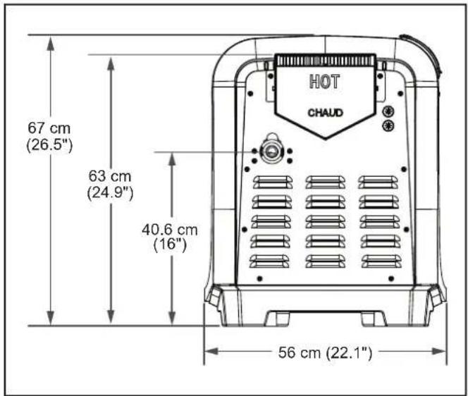
Figure 2. Side Dimensions
2.7 Certification Codes and Standards
| Certifi ed IAPMO | R&T Oceana |
| COMPLIANT Standard for 'Gas Pool Heaters', AS/NZS 5263 | |
| Applicable National Installation and Commissioning code(s) | Standard for Gas Installations, AS/NZS 5601Pay particular attention to the chapter addressing Venting of Equipment |
| All AstralPool Gas heaters must be installed in accordance with the local building and installation codes as per the utility or Authority Having Jurisdiction (AHJ). In the absence of local codes, please refer to the latest edition of the national codes for installation:The IXI pool and spa heaters meet or exceed the requirements of energy conservation regulations such as those in regions that have disallowed the use of continuously lit pilot type ignition sources. | |
2.8 HeaterComponents

Indicates a safety control equipped to protect internal components and extend the life of the heater.
a Flue Temperature Sensor Monitors temperature at the exhaust flue. If excessive temperatures are detected, combustion will stop and a fault will be displayed.
b Hot Surface Igniter When current is passed through the ceramic material of the igniter it will achieve temperatures great enough to initiate combustion of the air/fuel mixture.
C Ignition Control Provides energy for ignition, monitors flame quality and controls the gas valve. Upon call for heat, the blower is activated to purge the combustion chamber. Electrical power is then applied to the hot surface igniter. When ignition temperature is attained, the gas valve opens and ignition occurs. If stable flame is detected the igniter will power down. If stable flame is not detected the control system will close the valve to prevent further gas release. If a total of 3 ignition attempts fail an ignition fault is displayed.
d High Limit Switches Rated at 43°C (109°F), 52°C (126°F) and 66°C (151°F) will prevent water of excessive temperatures from being discharged from the heater. If the switch at the header inlet, or if either switch at the heat exchanger outlet senses excessive temperature, the gas valve will close and combustion will stop.
Pool/Spa Water Temperature Control Senses water temperature by means of a thermistor. Heater will operate to attain and maintain the water temperature according to the heater settings. Two separate thermostat settings are supported, typically used to set pool and spa temperatures.
f Water Pressure Switch Senses whether or not water is available to the heater by measuring back pressure at the header inlet. If insufficient pressure is detected, the display will indicate a "Check Flow" fault and combustion will stop.
⑨ Gas Valve Controls gas flow into the burner. Enables flow when the temperature control calls for heat and all safety controls enable operation. It also regulates gas pressure to -.05 kPa (-2" Water Column) below the air pressure at the blower inlet. Necessary pressure regulation cannot be accomplished with common (positive pressure) gas valves.
Combustion Blower and Air Orifice Draws in air and fuel gas creating an air/fuel mixture that is passed through the burner for combustion. The fan will operate for several seconds before flame initiation and after the flame is extinguished to purge the combustion chamber for a clean burn and to expel any residual exhaust gas.
Air Pressure Switch Monitors the vacuum (negative pressure) within the blower housing. This switch verifies that air is flowing through the combustion system by sensing pressure. If air flow is inadequate, combustion will stop and a fault will be displayed.
Section 3. Getting Started
Install the IXI in accordance with the procedures in this manual, local codes and ordinances, and in accordance with the latest edition of the appropriate national code. See Section 2.7.
If the heater is to be operated in below freezing conditions it should be installed in a protected outdoor shelter. See Section 4.2
All gas-fired products require correct installation to ensure safe operation. The requirements for pool heaters include the following:
• Field assembly (if required)
- Appropriate site location, clearances and flooring see Section 3
- Sufficient combustion and ventilation air
• Properly sized gas meter and piping
• Proper electrical wiring
- Sufficient water flow
This manual provides the information needed to meet these requirements. Review all applications and installation procedures before continuing the installation.
3.1 Contents
Before starting, check that you have the correct parts as indicated in Table 1. If any parts are missing or incorrect, please call your local distributor or technical support at 1300 186 875 for assistance.
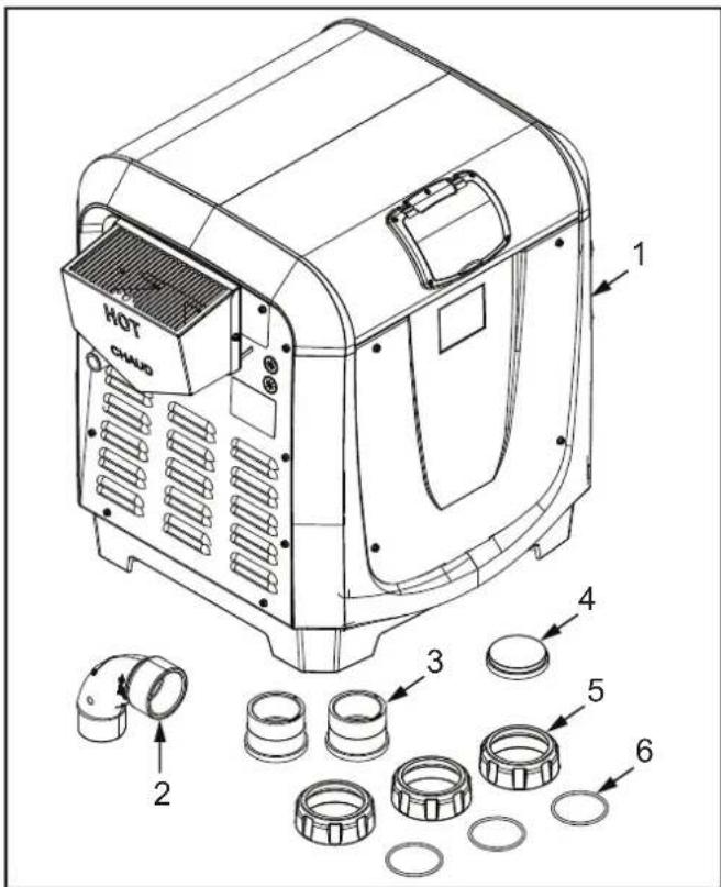
Figure 3. IXI Gas Heater Contents
| Item Description Quantity | ||
| 1 IXI Gas Heater 1 | ||
| 2 | Sweep Elbow | 1 |
| 3 | 50mm Universal Union Tail | 2 |
| 4 | 50mm Union Cap | 1 |
| 5 | 50mm Universal Union Nut | 3 |
| 6 | 50mm Universal Union O-ring | 3 |
Table 1. IXI Gas Heater Parts
3.2 Required Equipment
Please ensure that the following equipment is available to the installer at the time of installation.
3.2.1 Required Tools

Safety Eye Wear

Gloves

Philips Screwdriver

Flathead Screwdriver

Pipe Wrench

Adjustable Wrench

5mm (3/16") Hex Key

Multi Grips

Digital Differential Manometer

Voltage Meter

PVC Pipe Cutter
Power Drill

Tape Measure
Figure 4. Required Tools
3.2.2 Materials Supplied by Installer
Please ensure that all materials used during the installation are in accordance with local codes or the authority having jurisdiction (AHJ) requirements. If you have any questions regarding the materials that need to be used during this installation please call the AstralPool customer service center at 1300 186 875.
Indoor installations will require additional venting and exhaust conversion materials which are outlined in detail in Section 4.
NOTE: Required materials may differ from the materials listed. Be sure to confirm with all local and national codes before beginning the installation.
| Gas Supplies Electrical Supplies | Plumbing Supplies | |
| Appropriately sized Gas Piping | 230-240 VAC, 50 Hz PVC Piping | |
| Manual Gas Shut Off Valve | PVC Cement | |
| Gas Union Teflon Tape | ||
| Cap Red RTV | 300°C (600°F) | rated silicone adhesive |
| Leak Solution | ||
| 1.6 mm (1/16") Hose "T" | ||
| 3.18 mm (1/8") - 1.6 mm (1/16") Barbed Adapter | ||
| 1.6 mm (1/16") Flexible Hose | ||
Section 4. Location Requirements
WARNING
Improper installation or maintenance can cause nausea or asphyxiation from carbon monoxide in flue gases which could result in severe injury or death. For indoor installations, as an added measure of safety, AstralPool strongly recommends installation of suitable carbon monoxide detectors in the vicinity of this appliance and in any adjacent occupied spaces.
Incorrect design and installation of heater vents and ducts can result in personal injury, damage to property, or death. To avoid such hazards, the heater must be installed only by a qualified professional service technician.
The IXI heater is shipped from the factory with an exhaust vent configured for outdoor installation. The heater is designed and certified, per AS/NZS 5263 for both outdoor and indoor installation in Australia and for indoor and outdoor installation of natural gas only heaters in New Zealand. It is shipped from the factory configured for outdoor use only, and is intended for use with permanently installed, swimming pools only. It should be installed on a level, stationary, non-mobile location and should not be subjected to intentional movement, vibration, etc. which could negatively affect the plumbing, wiring, and venting of the heater. For installation indoors, be sure to follow all the instructions provided in this instruction manual. See Section 4.3 for details.
Location of the heater below or above the pool water level affects operation of its water pressure switch. See Section 6.3 for more information.
NOTE: If the heater is to be operated in below freezing conditions it should be installed in a protected outdoor shelter.
CAUTION
When pool equipment is located below the pool surface, a leak from any component can cause large scale water loss or flooding. AstralPool cannot be responsible for such water loss or flooding or resulting damage.
4.1 Clearances
The heater must be installed in a location that allows clearances for maintenance and inspection. Minimum distances from combustible surfaces must also be maintained. All criteria given in the following sections reflect minimum clearances as stated in the national standards. However, each installation must also be evaluated, taking into account prevailing local conditions such as wind speed and direction, proximity and height of obstructions that may block ventilation, and proximity to public access areas.
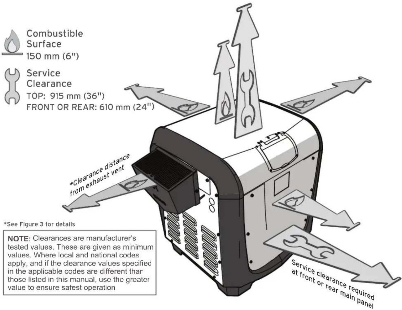
Figure 5. Clearances
Service Clearance: 91.5 cm (36") from top of heater for removal of top panel.
61 cm (24") from one of either the front or rear panels.
Combustible Surfaces: Each heater face requires a 15 cm (6") clearance from combustible surfaces. Although not preferred, the heater is design certified for installation on combustible surfaces for operation. However, do not install the heater on carpet.
4.2 OutdoorInstallation
Locate the heater:
- On a level solid surface.
- 3.5 m (12') from inner pool edge unless separated by a permanent solid barrier, i.e. a wall or fence.
• In an open area, not under a deck or other structure. - Away from doors, windows or louvres that connect in any way to occupied or inhabited areas of the building.
• Away from rainwater runoff. - Away from potential sprinkler water intrusion.
- So that the top of the heater is at least 1 m (3') below any overhang.
- So that the top surface of the heater is at least 1 m (3') above any forced air inlet within 3 m (10').
WARNING
Do not install the heater with the top of the vent assembly within 1.22 m (4') horizontally, 1.22 m (4') below or less than 300 mm (1') above any opening into a building. Local codes and installation requirements may vary.

Figure 6. Location Requirements
4.3 Indoor and Outdoor Shelter Installation
AstralPool does not encourage installation of ULPG (Universal LPG) gas heaters indoors. Always consult with the authority having jurisdiction (AHJ) along with all applicable national and local codes before installing a ULPG heater indoors. Please be sure to refer to Section 5.3.
The heater is Certified by IAPMO-R&T Oceana for indoor installations. Please keep in mind the clearances from Section 4.1 when selecting an installation location. You will also need to make considerations for intake combustion air see Section 4.3.1 and exhaust venting see Section 4.3.3. In addition, when pool equipment is installed indoors, appropriate containment measures and drains should be considered for the prevention of property damage in the event of an equipment leak.
NOTE: An outdoor shelter is an unoccupied enclosure which does not communicate directly with occupied areas.
If the outdoor shelter is a completely closed structure, air openings in accordance with the size recommendations described in Section 4.3.1 must be maintained. If the structure does not have outside air openings then air must be provided for combustion by using our fresh air vent kit.
4.3.1 Combustion Intake Air Supply
As outlined in the latest edition of ANSI standard Z223.1 (NFPA 54), the heater location must be properly vented to provide sufficient air supply for proper combustion. Please also consult Australian standards, AS/NZS 5263 and AS/NZS 5601.
When combustion air is supplied directly through an outside wall, each opening should have a minimum free area of 25.4 mm square (1 in ^2 ) per 1.2 kW input of the total input rating of all appliances in the enclosed area. If combustion air must pass through horizontal ducts, each opening should have a minimum free area of 25.4 mm square (1 in ^2 ) per 1.2 kW input of the total input rating of all appliances in the enclosed area. Details can be found in Figure 4.
The "Minimum Net Free Open Area" information from Figure 4 is not applicable in installations where exhaust fans or blowers of any type are used. Any equipment which exhausts air from the room where the heater is installed can deplete the combustion air supply or reverse the natural draft action of the venting system. This could cause flue products to accumulate in the room. Additional air must be supplied to compensate for such exhaust. Consult a professional engineer to ensure that installations where exhaust fans or blowers are used are designed and installed in accordance with all applicable local and national installation codes.
In addition, the heater must be completely isolated and protected from any source of corrosive chemical fumes or corrosive vapors (i.e chlorine or hydrochloric acid).
WARNING
Do not store any chemicals, cleaners, or other corrosive material near combustion air openings or in the room. Avoid locating appliance vents in the vicinity of combustion air openings. Failure to prevent corrosive materials from mixing with combustion air can result in reduced heater life and unsafe heater operation.

Figure 7. Indoor and Outdoor Shelter Installation
4.3.2 Direct Air Intake
In certain applications it may be necessary to supply intake air directly to the heater. You will need to order and install the direct air conversion R-Kit R0724600. A total equivalent length of 15 m (50') of 75 mm (3") PVC tubing can be used to bring the intake air directly to the blower input. Please be aware that each elbow used will account for 3.6 m (12') of length.

- For ease of access, remove the rear and top panels.
a Loosen the two screws securing the air orifice and screen in place. Remove the air pressure switch and gas valve hose from the air orifice.
b Remove the air orifice, separate and dispose of the orifice screen.
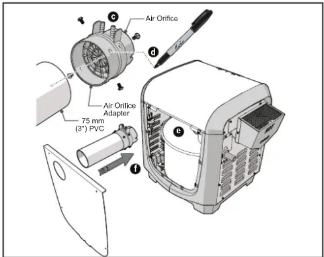
C Align the orifice adapter with the orifice tabs and secure with four screws.
d Dry fit the 75 mm (3') PVC tubing into the orifice adapter. Mark screw hole locations with a pen. Remove and drill pilot holes in the PVC. Fit the PVC into the orifice adapter, align the holes and secure with four screws
e Reinstall the air orifice and air hoses.
f Install the new rear panel over the PVC and secure with four screws.
4.3.3 ExhaustVenting
When the IXI heater is installed indoors or in an outdoor shelter the vent pipe sizing must be in accordance with the specifications listed in Table 2.
| CODES* | US | National Fuel Gas code ANSI Z223.1 (NFPA 54) | ||||
| AUS/NZ | IAPMO Oceana Standard for Gas Pool Heaters, AS/NZS 5263, AS5601 and/or Authority Having Jurisdiction (AHJ) | |||||
| STATIC PRESS. | STACK TEMP. | TERMINATION LOCATION | PIPE SIZING | MAX RUN LENGTH† | MATERIAL | |
| MODEL | PIPE SIZE | |||||
| Negative High | Roof (Vertical Termination) | 200 | 150 mm (6") | 11 m (35') | Aluminum inner pipe. Galvanized outer pipe. | |
| 370 | 200 mm (8") | |||||
*Ensure that you are referencing the latest edition and pay special attention to the chapter addressing "venting of equipment"
^ For each elbow installed, reduce the run length by 3.6 m (12'). If a vent run is required that will exceed a total equivalent length of 11 metres (35'), a draft inducer or external fan will need to be added to the system. If a vent run is required that will exceed a total equivalent length of 11 metres (35 ft), seek the assistance of a Registered Professional Engineer for proper design of indoor venting systems.
Table 2. Vent Pipe sizing Requirements
WARNING
Vent pipe materials, sizing, and installation must be as required by the National Fuel Gas Code NFPA 54/ANSI Z223.1 or Australia Standard for Gas Pool Heaters, AS/NZS 5263, AS/NZS 5601 Gas Installations as applicable by local code. Undersized pipe can result in inadequate venting and oversize pipe can result in vent condensation. Improper selection of vent pipe material, incorrect sizing of the pipe, and incorrect installation of vent piping can result in release of combustion products to the indoors. This can cause serious injury or death by Carbon Monoxide poisoning or asphyxiation.
WARNING
Improper installation or maintenance can cause nausea or asphyxiation from carbon monoxide in fl ue gases which could result in severe injury or death. For indoor installations, as an added measure of safety, AstralPool strongly recommends installation of suitable carbon monoxide detectors in the vicinity of this appliance and in any adjacent occupied spaces.
Incorrect design and installation of heater vents and ducts can result in personal injury, damage to property, or death. To avoid such hazards, the heater must be installed only by a qualified professional service technician.
- STATIC PRESSURE - NEGATIVE: Appliance operates with a negative vent static pressure, a vent gas temperature that avoids excessive condensate production and will vent vertically terminating at the roof. Termination must pass through a properly installed and approved roof jack, a properly sized storm collar and a listed vent cap. See Figure 4.
- Do not terminate heater vents near air conditioning or air supply fans which could pick up exhaust flue products, such as carbon monoxide and other hazardous effluent, and return them inside the building.
- Vent pipe type and material must be carefully selected and depends on the type of installation.
- Do not locate the vent terminal where exhaust flue products could strike against building materials and cause degradation.
- Vent opening should be well away from landscaping or other obstructions that would prevent free air flow to and from vent terminal.
- Do not terminate vent under decks, stairs, or car ports.
- Do not use the appliance to support the vent pipe.
- Vent piping must be supported with no low spots or sagging which could allow condensate to collect.
• Install the vent pipe so it can expand and contract freely with temperature changes. - Do not run the heater vent into a common vent with any other appliance.
-
It is recommended that vent runs over 5.5 m (18') be insulated to reduce condensation. Use a condensate trap in the vent run close to the heater, especially in cold climate installations.
-
Do Not install the heater in a sidewall terminated configuration or run exhaust venting in a primarily horizontal configuration. This heater is intended for vertical vented applications only.
- Horizontal runs of vent piping may be used but must not exceed 4.9 m (16 ft.) in length and must always maintain the minimum pitch/slope for any horizontal runs, as specified in Figure 4.
4.3.4 Indoor and Outdoor Shelter Exhaust Conversion
WARNING
Improper installation or maintenance can cause nausea or asphyxiation from carbon monoxide in flue gases which could result in severe injury or death. For indoor installations, as an added measure of safety, AstralPool strongly recommends installation of suitable carbon monoxide detectors in the vicinity of this appliance and in any adjacent occupied spaces.
Incorrect design and installation of heater vents and ducts can result in personal injury, damage to property, or death. To avoid such hazards, the heater must be installed only by a qualified professional service technician.
The heater can be fully converted to indoor exhaust type. In order to complete the conversion you will need to install the appropriate vent adapter.
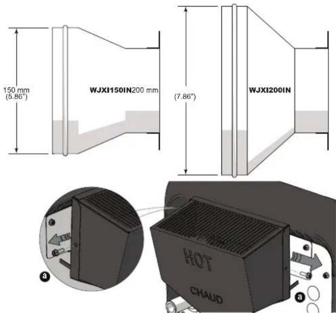
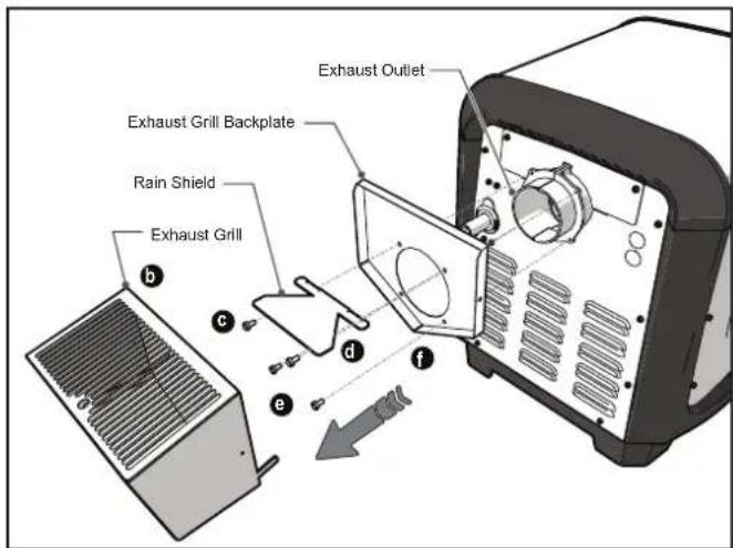
a Remove two screws securing the exhaust grill to the exhaust grill backplate.
b Remove exhaust grill.
Remove the two screws securing the rain shield to the exhaust backplate.
d Remove the rain shield.
e Remove the remaining two screws securing the exhaust backplate to the exhaust outlet.
natural_image
Illustration of a portable radio device with a speaker cone and labeled parts (no text or symbols)f Remove the exhaust backplate.
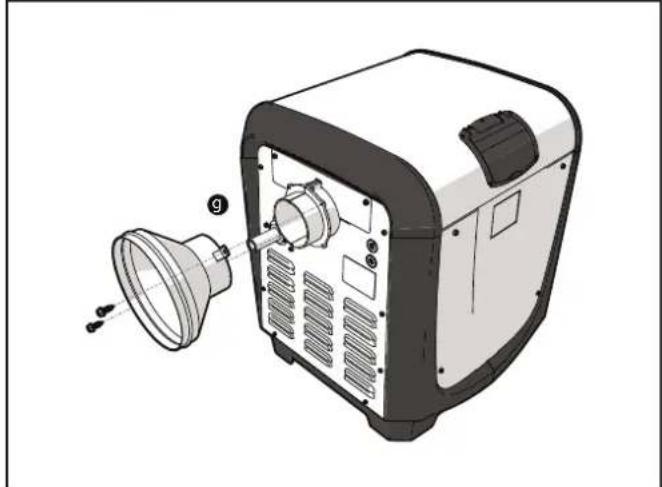
9 Using two #10 thread cutting screws secure the vent adapter to the exhaust outlet.
h Using red RTV 300°C (600°F) rated silicone adhesive run a bead of sealant around the interior joint of the adapter and the exhaust outlet.
When using parts or materials from other manufacturers please be sure to follow the manufacturers instructions completely to ensure harmonious function.

4.3.5 Precautions Against Common Venting
Seek the assistance of a Registered Professional Engineer for proper design of a common venting system.
AstralPool does not recommend using a common vent to vent multiple appliances through a common duct. However, if no other option is deemed available by the installer, each appliance must have its own vent temperature limit switch. All vent limit switches must be wired in series so as to prevent any appliance from firing in the event of a blocked vent. An outside draft inducer must be installed to pull and create negative pressure in the vent system. Refer to ANSI Z223.1 or Australian standards applicable to Gas Pool Heaters, AS/NZS 5263, AS/NZS 5601 for more information on common venting multiple appliances. Do not connect vent systems of different categories to the same venting system.
4.3.6 Inspection and Replacement of Existing Vent System With New Components
When replacing an existing pool heater with the IXI, it is recommended that a new appropriate venting system is installed with the new heater. However, if the existing venting system must be used, be sure to carefully inspect the existing system to ensure that it is in good condition and appropriate for the IXI heater. Replace any parts that are not in serviceable condition before completing the installation.
Section 5. Gas Connections
Gas piping installation must be in accordance with the latest edition of ANSI Z223.1 and the Australia standard installations, AS/NZS 5601.1 along with all local codes.
- Pressure Testing: The heater must be isolated from the gas supply piping system by closing the individual manual shut off valve during any pressure testing of the gas supply piping system at test pressure greater than or equal to 3.5 kPa (.5 psi).
CAUTION
Permanent damage to the gas valve will occur if the installation procedures are not followed correctly.
WARNING
CONVERTING THIS HEATER FOR USE WITH ANY OTHER FUEL TYPE IS NOT RECOMMENDED BUT, WHEN NECESSARY, SHOULD ONLY BE PERFORMED BY A LICENSED AND QUALIFIED PROFESSIONAL, AND ONLY AFTER CONTACTING ASTRALPOOL FOR THE PROPER INSTRUCTIONS AND CONVERSION KIT.
All questions should be directed to the AstralPool customer service center at 1300 186 875.
5.1 Supply Gas Requirements
- Refer to AS/NZS 5601.1 for correct gas inlet piping length from the gas meter to the heater.
- Confirm correct supply pipe size and supply pressure before proceeding with the installation.
- Check the gas meter to make sure it will supply enough gas to the heater and any other appliances using the same gas supply. If unsure, contact your local gas utility to confirm.
- It is critical that the incoming gas supply pressure at the heater is within the maximum and minimum pressure requirements as outlined in Table 2. If the range of acceptable supply pressure is not provided, the gas supply system to the heater must be modified to meet pressure requirements.
- Consider pipe fittings when determining gas pipe sizing. For every elbow used add 900 mm (3') to straight pipe length.
• Install a manual gas shutoff valve outside the heater body for service and safety. Never install the shutoff valve inside the body of the heater. - Where required by local code, install a sediment trap/condensate fall and gas union in accordance with Australia standard 5601. See Figure 5
- Do not use a restrictive gas cock.
ATTENTION
Do not use fl exible appliance connectors on any gas connections unless the connector is AGA approved for outdoor installation, and is marked with the BTUH capacity (which must be equal to or greater than the heater rated input) and the type of gas (Natural or ULPG). Also, any fl exible connectors, such as CSST buried underground must be certified for underground installation and meet all applicable codes. Please note, use of fl exible connector still requires the installation of a sediment trap. See Figure 5.
NOTE: The gas line from the meter is usually larger than the gas valve. Therefore, you will need to reduce connecting pipe as necessary. Make this reduction as close to the heater as possible.
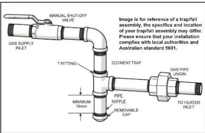
Figure 8. Manual Shutoff Valve and Sediment Trap
5.2 Inlet Gas Pressure Test
Before the heater can be put into service it is necessary to test the input gas pressure to ensure that it falls within the required range as outlined in Table 3.
| INLET GAS PRESSURE | NG(NATURAL GAS) | UNIVERSAL LPG | ||
| KPA | INCHES W.C. | KPA | INCHES W.C. | |
| MAX | 2.6 10.5 | 3.5 14 | ||
| MIN | 1.13 4.5 | 1.0 4.0 | ||
- All readings must be made while heater is operating.
- Relying on any reading taken while heater is off may result in poor performance and difficulty in operation.
Table 3. Supply Gas Input Pressure Requirements
- Verify the manual gas shutoff valve is open.
• Make sure the heater is off. - Remove the heater rear panel to expose the gas valve.
NOTE: The rear panel is the main body panel closest to the gas inlet. This may appear to be the front panel if the user interface was moved to accommodate a left side water connection. For instructions on moving the user interface see 6.2.1.

a Locate the inlet pressure tap on the gas valve.
b Using a small flathead screwdriver (ideally .100" width or smaller), turn the tap plug 2-3 turns counter clockwise.
CAUTION
Do not back the tap screw entirely out of the inlet pressure tap. The screw is small and easily lost. A lost screw needs to be replaced before the heater can operate.
C Connect positive manometer lead to the inlet pressure tap.
- Turn the heater on.
- Inlet gas pressure must be taken while the heater, and if possible, all other gas burning appliances supplied by the same gas delivery system, are operating.
- If the gas supply pressure is less than required. Check for an undersized pipe between the meter and the heater, a restrictive fitting, or an undersized gas meter. Make adjustments and perform the test again. If needed contact the local gas utility company for assistance.
- Once proper inlet pressure has been confirmed, turn off heater.
- Remove manometer.
- Tighten the tap plug securely. DO NOT OVERTIGHTEN.

WARNING
Failure to secure or replace the pressure tap plugs will allow gas to leak from the valve into the heater body which could result in property damage, severe injury, or death.
- Before operating the heater, test the gas supply system and all connections for leaks using a soap solution. Do not use an open flame to test for leaks.
5.3 Special Precautions for ULPG Gas
This appliance is approved for use with Universal LPG (ULPG) and Natural Gas in Australia and New Zealand. Under the same environmental conditions, ULPG is denser or heavier than air and will more readily collect or pool in enclosed areas if adequate ventilation is not provided. It is not recommended to install ULPG gas heaters in enclosed areas such as pits. Locate heaters a safe distance from ULPG gas cylinders and filling equipment. Consult the Australian / New Zealand Standard AS/NZS 1596 and gas installation standard AS/NZS 5601, and any other local codes and fire protection authorities about specific installation restrictions in your area.
For ALL installations the combustion air openings requirements and AS/NZS 5601 MUST be followed for safe and proper operation.
Section 6. WaterConnections
Install pool system components with connections as illustrated in Figure 6. Any configuration other than as illustrated in Figure 6 can affect the operation of the water pressure switch. Locating the heater above or below the pool water surface can also affect operation of the water pressure switch.
NOTE: When pool equipment is located below the pool surface, AstralPool is not responsible for any large scale water loss, flooding or damage caused by a leak.
CAUTION
The pool equipment must be protected from back-siphoning of water. If there is any chance of back-siphoning, provide a check valve between the pool and the filter pump inlet.
6.1 PumpSizing
The flow bypass within the heater manifold will accommodate flows rates delivered to the heater from a minimum of 114 Litres per minute (lpm) (30 gpm) to a maximum flow of 379 lpm (100 gpm.)
CAUTION
The system water pump must be capable of providing no less than 114 lpm (30 gpm) of flow through the heater. Flow rates at less than 114 lpm (30 gpm) may cause nuisance operation causing the heater to turn off or damage to the heater.
| MODEL MIN LPM (GPM) MAX LPM (GPM) | |
| IXI 200 | 114 (30) 379 (100) |
| IXI 370 | 114 (30) 379 (100) |
Table 4. Recommended Flow Rate Adjustment
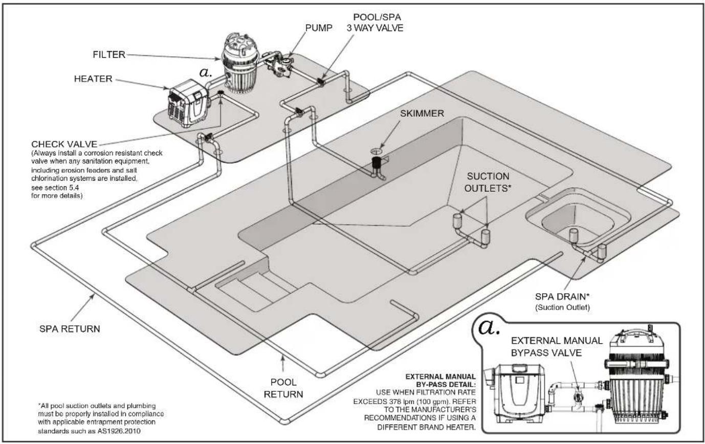
Figure 9. Typical Water Piping Configuration


line
| Flow Rate (lpm) | Design Head Loss (metres head) | Design Pressure Drop (kPa) | | --------------- | ------------------------------- | -------------------------- | | 120 | 0.2 | 6.9 | | 160 | 1.5 | 13.8 | | 200 | 2.6 | 27.6 | | 240 | 3.5 | 34.5 | | 290 | 4.5 | 41.4 | | 340 | 4.8 | 48.3 | | 380 | 5.0 | 55.2 |Figure 10. Head Loss Chart
6.1.1 Manual Bypass Valve
A manual bypass valve is to be installed in any system in which the pump flow exceeds 378 lpm (100 gpm). Connect ball valve between water inlet and outlet. See inset "a." in Figure 6.
- Adjust the valve to bring the flow rate within the acceptable range. See Table 3.
- Remove the valve handle to avoid tampering.
6.1.2 Pump Sizing for New Pool Construction
When sizing a pump for the system, the head loss for all system components must be added together when determining the design flow rate. Component "Head Loss at Flow" curves are available from equipment manufacturers.
NOTE: In order to properly establish head loss at flow for a filter, remember that a "dirty" filter can typically add 69 kPa (10 psi) of additional head loss, 7 extra metres (22') of head. This must be considered when sizing a pump for a new pool system.
6.1.3 Pump Sizing for Replacement in an Existing Pool
If the IXI heater replaces a different model of heater, determine if the existing pump is capable of providing the minimum flow of 114 lpm (30 gpm). IXI heaters are high efficiency heaters. Heaters typical of this construction may have higher head loss characteristics than the one being replaced.
CAUTION
Heater failure due to insufficient water flow is not covered under warranty. See measurements in the Head Loss Chart. See Figure 7.
6.2 Plumbing Connections
The heater has a standard 50 mm (2") water manifold and coupling design. With this feature, only nominal 50 mm (2") PVC or CPVC may be connected to the heater. AstralPool recommends the use of 50mm (2") pipe with a minimum of 40mm (1.5") to be fitted to the heater.
6.2.1 Reverse Plumbing Connection
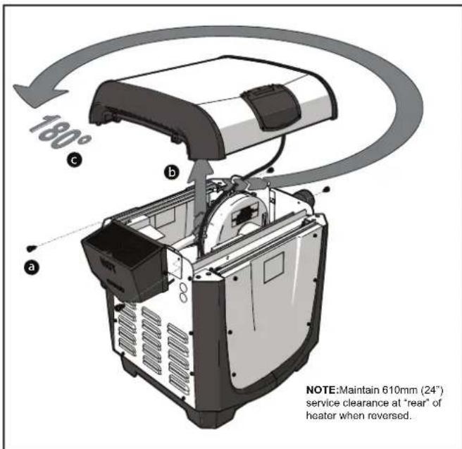
The IXI heater is shipped with the manifold on the right side by default. If necessary the water connections can be orientated to the left side by rotating the top panel of the appliance.
NOTE: The electrical raceway, transformer, PIB, Ignition control and voltage selector board are all accessed through the default front panel. Special considerations should be made for service clearance, see Figure 2, before a final location and orientation for the appliance is determined.
- Turn off all power to the heater at the breaker.
- Ensure that the pump is off and will remain off for the duration of the procedure.
a Remove the four black screws securing the heater top panel to the heater body.
b Lift heater top panel. Be careful not to damage or apply undue stress to the user interface wiring.
© Rotate the heater top panel 180°.
- Place heater top panel securely on heater body.
- Secure with the four screws removed in step "a".
- Restore power to the heater.
- Return heater to normal operation.
6.2.2 Water Inlet Piping
There are two options for water inlet connections on the IXI. Both configurations use the same water outlet to return heated water to the pool. Be sure to check flow rates as outlined in Section 6.1 and if necessary make provisions for and ensure sufficient space for the installation of a manual bypass valve as outlined in Section 6.1.1
The top inlet is intended for use with the Versa Plumb™ sweep elbow. Plumbing in this configuration can increase hydraulic efficiency particularly when used in a system with other Versa Plumb™ compatible Equipment. See Figure 12.
The side inlet is positioned at a 26 cm (10.13") center height providing an ideal height for replacement or new construction plumbing.
- Turn off all power to the heater at the breaker.
• Turn off main gas supply to heater.
- Ensure that the pump is off and will remain off for the duration of the procedure.
- Do a dry fit test of cut pipe lengths in order to ensure proper seating of the union tailpiece and o-ring. Make adjustments to pipe length or positioning as needed.
- Clean all adhesion surfaces with an appropriate NSF® approved all purpose cleaner/primer.
- Slide the union nut onto the cut pipe length or sweep elbow. Ensure proper nut orientation with threads directed towards the heater manifold. See Figure 12.
- Use approved NSF adhesive to glue the tailpiece onto the cut pipe, or sweep elbow.
NOTE: AstralPool recommends Weld-On® 724TM PVC to CPVC Cement to glue Schedule 40 PVC.

Figure 11. Versa Plumb Heater Inlet
- Align tailpiece and manifold orifice.
- Secure union nut over tailpiece hand tight only. Be sure that the o-ring is properly seated. Do not overtighten. Do not use pipe joint or tape.
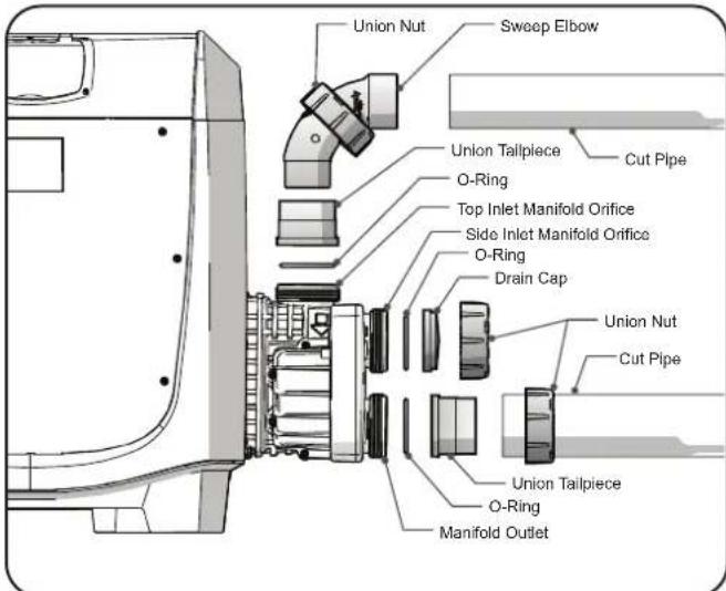
Figure 12. Inlet Piping
- If using the sweep elbow. Use approved NSF adhesive to glue the sweep elbow into the tailpiece and onto the cut pipe.
- Repeat the above steps for the manifold outlet. Again paying special care to ensure proper seating of the union tailpiece o-ring.
- Install the union nut and drain cap with o-ring at the unused inlet on the heater manifold. Be sure that the o-ring is properly seated. Secure hand tight only. Do not overtighten. Do not use pipe joint or tape.
- Return all valves to their operating positions.
- Restore power to the heater at the breaker.
- Turn on pump and inspect carefully for leaks.
- Restore main gas supply.
- Start the system and check for proper flow.
- Return heater to normal operation.
WARNING
To avoid an electrical shock hazard, which can result in serious injury or death, ensure that all electrical power to the system is turned off before approaching, inspecting or troubleshooting any leaking valves or plumbing that may have caused other electrical devices in the surrounding area to get wet.

Follow all fi lter manufacturer's instructions. Never attempt to assemble, dis as sem ble or adjust the fi lter when there is pressurized air in the system. Starting the pump while there is any pressurized air in the system can cause the fi lter lid to be blown off, which can serious personal injury or property dam age
6.3 Water Pressure Switch Adjustment
The water pressure switch is located inside the heater jacket on the water connection side See Section 2.8, item "f".
The switch is preset at the factory. The pressure switch setting must be adjusted if the heater is installed:
• Below the surface level of the pool
- More than 600 mm (2') above the pool level
- Where the pressure is measured at 6.9 kPa (1 psi) or greater with the filter pump off
If the heater is installed more than 1.2 metres (4') above or below the pool water level, a Pressure Switch is no longer sufficient. A Flow Switch must be installed as well.
CAUTION
The water pressure switch should be adjusted to turn the heater off when the pump is off. Setting the switch to close at too low flow can damage the appliance. Adjust the switch to turn the heater off, not on.
NOTE: It is recommended that a Pressure Release Valve (PRV) be installed prior to taking any of the steps below.
Location of the heater above or below the pool water surface can also affect the operation of the switch. If the heater is installed more than 1.2 metres (4') above or below the pool water level, a Pressure Switch may no longer be sufficient, and a Flow Switch may need to be installed as well. The factory installed switch can accommodate elevations of 1.8 m (6') above the pool water surface or 3.4 m (11') below pool water surface. If the heater water connections are outside this range, a Flow Switch must be installed. Please contact a pool professional or your local AstralPool representative for additional recommendations.
- Set the heater control to "OFF".
- Remove five screws securing the side panel to the heater body.
- Remove the side panel to gain access to the water pressure switch. See Figure 13.
- Turn the filter pump on.

Figure 13. Water Pressure Switch Adjustment
- Confirm that the pressure switch closes with a voltmeter.
- If the switch does not close, check that all valves are open to the heater and that there are no restrictions in the line. You may also need to confirm flow rate from your pump as outlined in Section 6.1.
- Once an operational and correctly sized pressure switch has been confirmed, set the heater control to either POOL or SPA.
- With your fingers, turn the adjustment sprocket very slowly clockwise until the heater shuts off.
- Slowly turn the pressure switch adjustment sprocket counterclockwise one-quarter turn. The heater should come back on. See Figure 13.
- Check the adjustment by turning the filter pump OFF. The burner should shut off immediately.
- If it does not, restart the filter pump and repeat the preceding step.
- Check the adjustment again. If you are still unable to successfully set your water pressure switch please contact your local AstralPool distributor or call technical support at 1300 186 875. Additional information can be found at www.AstralPool.com.au.
- Return the pool temperature control to the desired temperature.
- Return heater to normal operation.
6.4 Check Valve Installation
When any equipment is located below the surface of the pool or spa, back-siphoning can occur, which can draw water backwards through the circulation system. This can be particularly concerning if chemically treated water is allowed to flow back into equipment such as heaters, filters and pumps. Make sure any chemical feeder or chlorination system outlet lines are downstream of the heater. Install a positive seal noncorrosive check valve between the sanitation equipment and the heater. Always install a check valve if there is sanitation equipment installed in the system. Do not install any shutoff valve in the piping between the heater outlet and the pool.
WARNING
A check valve can interfere with the proper operation of certain Suction Vacuum Release System (SVRS) products. To avoid possible entrapment hazard, serious injury, or death, make sure to review the operation/owners manual of your particular SVRS product before installing the check valve.
6.5 Pressure Relief Valve (PRV) Installation
A pressure relief valve (PRV) is recommended in all installations, and is mandatory in any installation in which the water flow can be shut off between the heater outlet and the pool/spa.
A pressure relief valve is not supplied with the IXI heater. However, it is recommended that a pressure relief valve be installed and may be required by local or national codes. Be sure to check any applicable installation codes in your area to determine whether a pressure relief valve is required. If one is required, it must meet the requirements below and must be provided and installed by the installer
The maximum working pressure of this heater is 345 kPa (50 psi). Be sure to take into consideration the maximum allowable pressure of the other components in the system when installing a PRV. Any pressure relief valve installed must comply with provisions of the standard.
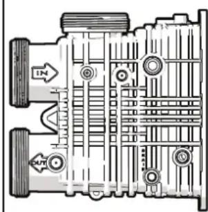
Installation procedure will differ depending on which header type is installed on your heater. See Figure 14.
- The PRV must be compliant to AS1357.1 or ASME certified.
- Relief pressure must be at 3.45 bars (50 PSI)
- Minimum rating of 7.77 Kilowatts or 125.8 kg/hr steam rating.
• Install the PRV so that it is vertical. See Figure 12.
• Install a drain pipe from the pressure relief valve outlet to a safe area. This is a precaution to prevent the possibility of personal injury or property damage in the event scalding water is discharged from the pressure relief valve.
- Install the discharge pipe so that there is no trapped or standing water in the piping. Discharge piping must be facing down, terminating with a threadless nipple, no more than 6" and no less than twice the diameter of the discharge pipe from the floor. Discharge piping must be open with no reducers or shut-off valves or other restrictions.
NOTE: To ensure the continued proper operation of the pressure relief valve, the valve should be tested once a year. To test, lift the lever with the circulation system running to ensure that water will pass through. When the lever is down, there should be no leaks from the outlet.
Header Type "A" Header Type "B"

natural_image
Technical diagram of a mechanical assembly with no visible text or symbolsFigure 14. HeaderType
6.5.1 Header Type "A" (PRV) Installation
- Locate the water outlet port on the inlet/outlet header side of the heater. This is the bottom port which returns water to the pool and/or spa. See Figure 16.
NOTE: PVC and or brass fittings must be installed immediately after the outlet with no valves or other components in between. The pressure relief valve must be installed at the outlet port. Do not install at the header inlet port.
CAUTION
In order to prevent damage, do not tighten with a wrench. Hand tighten only and use caution not to over-tighten. Overtightening may crack the header.
Use Teflon tape only on threads mating brass components to the plastic reducer fi tting. Do not use any pipe compound or pipe dope on the threads or any part(s) that come(s) into contact with plastic. These compounds can damage plastic components over time.
- Using PVC or CPVC plastic pipe and fittings, install a 50 mm (2") tee. See Figure 15.
• Install an elbow and a reducer fi tting. Make sure the internal pipe thread on the reducer fi tting matches the thread on the pressure relief valve.

Figure 15. Pressure Relief Valve install
6.5.2 Header Type "B" (PRV) Installation (not provided by AstralPool)
- Locate the threaded boss on the outlet port of the header, and find the dimple at the center. See Figure 16.
- Use the dimple to center the drill bit.
- Drill a 9.5 mm (3/8") diameter hole through the boss.
- Take care not to damage the surrounding plastic threads. Drilling a 3 mm (1/8") diameter hole first will help prevent thread damage.
- Install a 19 mm (3/4") threaded nipple, elbow and the pressure relief valve. Make sure to get a sung fi t. Do not overtighten.
CAUTION
In order to prevent damage, do not tighten with a wrench. Hand tighten only and use caution not to over-tighten. Overtightening may crack the header.
Use Tefl on tape only on threads mating brass components to the plastic reducer fi tting. Do not use any pipe compound or pipe dope on the threads or any part(s) that come(s) into contact with plastic. These compounds can damage plastic components over time.
Discharge piping must be open with no reducers, or shut-off valves, or other restrictions.

Figure 16. Pressure Relief Valve install
6.6 Auxiliary Components, Chlorinators, Ozone Generators and Sanitizing Chemicals
The IXI heater is manufactured with materials that are not compatible with high concentrations of ozone, chlorine, bromine, or other sanitizing chemicals. Heater damage caused by improper water chemistry or plumbing configurations are not covered by the AstralPool warranty. All questions should be directed to technical support at 1300 186 875. Additional information can be found at www.AstralPool.com.au. Be sure to adhere to the following:
- All sanitation equipment is to be installed as the last piece of equipment in the circulation system.
- When ozone is used, install a mixing degas chamber, to prevent ozone and air from entering the heater.
- When chemical feeders are used, install an in-line check valve between the heater and the feeder.
- Wire any electrical sanitation equipment so that it cannot operate unless the filter pump is running.
- Always follow pool chemical manufacturer's instructions when adding chemicals to pool.
Section 7. Electrical Connections
Wiring connections must be made exactly as shown in the wiring diagram found on the inside of the heater door. If local code also requires that the equipment and/or appliances associated with the pool water circulating system, including, but not limited to, pump motors and heaters, be bonded together as part of the equipotential bonding grid. AstralPool provides a special labeled bonding lug on the manifold side of the heater to accommodate this requirement.
All electrical connections and wiring must be done by a certified electrician only. Electrical wiring must also be in accordance with the latest edition of the AS/NZS 5601, AS/NZS 3000, along with all local codes.
The heater comes factory-wired for installation with 230 Volt, 50 Hz AC field electrical supply.
WARNING
ELECTRICAL SHOCK HAZARD. This heater contains wiring that carries high voltage. Contact with these wires may result in severe injury or death.
CAUTION
Label all wires prior to disconnection when servicing controls. Wiring errors can cause improper and dangerous operation.
Verify proper operation after servicing.

flowchart
graph TD
    A["240-230 VAC Heater Power Supply"] --> B["BL BR BL BR GY G"]
    B --> C["ACN1 F1 BL BR BL ACH1 BK"]
    C --> D["BLOWER MOTOR"]
    D --> E["FUSE"]
    E --> F["TRANSFORMER"]
    F --> G["R 24 VAC Y"]
    F --> H["W BL BL BL BL BL BL BL BL BL BL BL BL BL BL BL BL BL BL BL BL BL BL BL BL BL BL BL BL BL BL BL BL BL BL BL BL BL BL BL BL BL BL BL BL BL BL BL BL BL BL BL BL BL BL BL BL BL BL BL BL BL BL BL BL BL BL BL BL BL BL BL BL BL BL BL BL BL BL BL BL BL BL BL BL BL BL BL BL BL BL BL BL BL BL BL BL BL BL BL BL Bl Bl Bl Bl Bl Bl Bl Bl Bl Bl Bl Bl Bl Bl Bl Bl Bl Bl Bl Bl Bl Bl Bl Bl Bl Bl Bl Bl Bl Bl Bl Bl Bl Bl Bl Bl Bl Bl Bl Bl Bl Bl Bl Bl Bl Bl Bl Bl Bl Bl Bl Bl Bl Bl Bl Bl Bl Bl Bl Bl Bl Bl Bl Bl Bl Bl Bl Bl Bl Bl Bl Bl Bl Bl Bl Bl Bl Bl Bl Bl Bl Bl Bl Bl Bl Bl Bl Bl Bl Bl Bl Bl Bl Bl Bl Bl Bl Bl Bl Bl BIK NO NC AIR FLOW SWITCH BYBK C NO AC AIR FLOW SWITCH BYBK NO AC AIR FLOW SWITCH BYBK NO AC AIR FLOW SWITCH BYBK NO AC AIR FLOW SWITCH BYBK NO AC AIR FLOW SWITCH BYBK NO AC AIR FLOW SWITCH BYBK NO AC AIR FLOW SWITCH BYBK NO AC AIR FLOW SWITCH BYBK NO AC AIR FLOW SWITCH BYBK NO AC AIR FLOW SWITCH BYBK NO AC AIR FLOW SWITCH BYBK NO AC AIR FLOW SWITCH BYBK NO AC AIR FLOW SWITCH BYBK NO AC AIRF BAY Pass Accessory"]
    subgraph Factory Wired 24V
        direction TB
        B["WORK"] --> C
        C --> D
        D --> E
        E --> F
        F --> G
        G --> H
        H --> I["FOR AIR FLOWER STARTER (IF USED)"]
        I --> J["UNITED CONTROLLER USER INTERFACE POWER INTERFACE"]
        J --> K["FL TEMPT PERMATE LIMIT 240°C (464°F)"]
        K --> L["UNITED CONTROLLER USER INTERFACE POWER INTERFACE"]
        L --> M["UNITED CONTROLLER USER INTERFACE POWER INTERFACE"]
    end

    subgraph Factory Wired 120V/240V
        direction TB
        N["WORK"] --> O["FOR AIR FLOWER STARTER (IF USED)"]
        O --> P["UNITED CONTROLLER USER INTERFACE POWER INTERFACE"]
        P --> Q["UNITED CONTROLLER USER INTERFACE POWER INTERFACE"]
        Q --> R["UNITED CONTROLLER USER INTERFACE POWER INTERFACE"]
    end

    style Factory Wired 24V fill:#f9f,stroke:#333
    style Factory Wired 120V/240V fill:#bbf,stroke:#333
Figure 17. IXI Connections/ Schematic Wiring Diagram
7.1 ServiceAccess
- Remove the four screws holding the front heater panel in place to expose the raceway.
a Locate the raceway lock release on the interior of the heater raceway.
b Using a screwdriver or comparable tool; press into the raceway release orifice until the raceway latch releases, and the raceway swings free.
C Secure the raceway in place by lifting until the Locking latch engages.
d Push the tab on the locking latch to the left to release.
- Press raceway down and back until an audible click indicates that it is latched in position.
- Replace heater front panel.
NOTE: Before the raceway can be rotated for the first time a shipping zip tie must be cut. This zip tie is threaded at the raceway release point see item (a) below. While cutting this zip tie be sure not to damage or abrade any of the wires.

7.2 Bonding
AstralPool requires that the appliance be connected to a "bonding loop" that includes all electrical equipment in the system and on the equipment pad. Bonding lugs must be connected with a solid copper wire at least 10mm^2 . Failure to do so will void the warranty.
Additionally, the Australian Wiring Rules (AS/NZS 3000) require that all metallic components of a pool structure, including reinforcing steel, metal fittings and above ground components be bonded together (forming an "equipotential bonding grid") with a solid copper conductor not smaller than an 6mm^2 .
CAUTION
To prevent premature failure of the appliance resulting from stray voltages and voltage differentials, the heater must be bonded to other equipment which is part of the pool plumbing system with a solid copper wire not smaller in diameter than 8 AWG.
Section 8. Optional Remote Controls
The IXI heater controls can be wired for remote operation. Viron Connect Control Systems will permit the heater to be operated by remote control. Please note only suitable for Touchscreen firmware 3.6 or higher. This was introduced in July 2018. Connect 10 firmware needs to be version 2.2 or higher. This was introduced in November 2015. The instructions in the following sections should be used as a general guideline only. Please follow the instructions that accompany your selected control system thoroughly.
Electrical wiring must be in accordance with the latest edition of the Australian Wiring Rules (AS/NZS 3000) and all other applicable installation codes.
Refer to Figure 17 for a complete diagram of wiring connections and terminals.
8.1 Connecting to a Remote Pool-Off-Spa Selector (3-Wire Connection)
- Turn off the power to both the pool/spa control system and the heater unit.
- Remove the front panel.
- Run the wires from the pool/spa control system through the low voltage knockout on the right or left-hand side of the heater. See Figure 22.
- Connect the wiring from the pool/spa control system to the heater remote control terminal. See Figure 17 item "b".
- Connect the three wires to Spa, Pool & Common terminals of the J6 terminal bar.
- Reinstall front panel.
- Restore power to the heater and the pool/spa control system.
8.1.1 Configure the Control Panel
- Make sure the pool heater line voltage is ON.
- Pool and spa temperature control settings must be OFF.
- Press and hold MENU, then the POOL and SPA buttons for 5 seconds to access Service Setup mode.
- Press Up or Down to display REMOTE.
- Press MENU, REMOTE OFF (default remote) is displayed.
- Use Up or Down to scroll through the Remote options until HI-LO-COM is displayed, then press MENU to select.
- Press POOL or SPA to exit Service Setup mode.
NOTE: The display will revert back to OFF after 1 minute since the last key press.
8.2 Connecting to a Remote TSTAT (2-Wire Connection)/AstralPool Intelli-Heat Controller
An interrupt (on/off-type) remote can be connected as a Remote TSTAT to turn the heater on or off but not perform any other function. AstralPool Intelli-Heat controllers also use this function. When using this type of connection, remember to set the heater control to "SPA" and set the thermostat control to maximum.
8.2.1 Installing the Remote TSTAT/AstralPool Intelli-Heat Connection
- Turn off the power to both the pool/spa control system and the heater unit.
- Remove the front panel.
- Run the wires from the pool/spa control system through the low voltage knockout on the right or left hand side of the heater.
- Connect the wiring from the pool/spa control system to the heater remote control terminal.
- Connect the two wires to Pool and Common (not Spa) on the J6 terminal bar. See Figure 17 item "b".
- Reinstall panel.
- Restore power to the heater and the pool/spa control system.
NOTE: If you install a time clock to control the filter pump operation, it is recommended that the time clock have its own low voltage (Fireman's) switch to turn off the heater before turning off the pump. The switch should shut off the heater about 15 minutes before the filter pump shuts off. This will allow for a more efficient operation by removing any residual heat contained in the heat exchanger back to the pool.
CAUTION
To avoid damage to the heater, do not connect the power supply of the heater to the output side of the clock if your time clock simply interrupts the high voltage power supply or has a high voltage output. Doing so will prevent the blower from purging the residual heat from the heater when the heater turns off. The blower must be allowed to run for 45 seconds after the heater shuts off.
8.2.2 Configure the Control Panel
- Make sure the pool heater is OFF.
- Press and hold MENU, then the POOL and SPA buttons for 5 seconds to access Service Setup mode.
NOTE: The display will revert back to OFF after 1 minute since the last key press.
- Press MENU, REMOTE OFF (default remote) is displayed.
- Use Up or Down to scroll through the Remote options until REMOTETSTAT is displayed, then press MENU to select.
- Press POOL or SPA to exit Service Setup mode.
- Press SPA to adjust the set point to the maximum 40^ .
8.3 Connect To A Viron Connect or "Smart" Communication Via RS-485
When connecting an AstralPool IXI gas heater to the AstralPool VIRON Connect controller, an RJ12 cable needs to be plugged into the heater's thermostat via the RS485 connection. This is achieved through an IXI gas heater interface module (Sold Separately – Part Number: 14608) and installed inside the heaters electrical access panel via the power interface board.

natural_image
Coiled cable with connectors and a rectangular device attached (no text or symbols visible)Figure 18. IXI Gas Interface Module
- When connecting any appliance via a data cable to the VIRON Connect electrical box, it is important to only use straight-through 6-wire cable. Many off the shelf data/phone cables are cross-over configuration, or only have 4 wires, and cannot be used with the VIRON control system. The IXI Gas Heater Interface includes a 5m Grey RJ12 cable. Alternatively-sized RJ12 cables of varying lengths are also available from your local AstralPool Australia distributors.
- There are six (6) RJ12 sockets located inside the VIRON Controller. Any appliance can connect to any socket.

Figure 19. IXI to Viron ConnectPower Connection
Note: Power for the IXI heater should always be connected into the designated constant 240V power outlet on the Viron Connect to ensure continuous power. If power is connected elsewhere, you can sometimes get a "phantom" display on the heater due to power on the communications line. This will power up the screen on the thermostat, but the heater will not function.
Installing the IXI Interface Controller for use with AstralPool Connect 10 Systems
- Ensure the heater has been disconnected from power.
- Remove 4 screws on the front panel to remove the cabinet door and access the heater PCB.
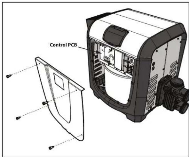
Figure 20. Remove IXI Cabinet Access Door
- Release the lift-up electrical raceway to easily access the control pcb. See Section 7.1 for further details.

Figure 21. IXI RS485 Connector Wiring
- The IXI interface controller comes prewired with an RS485 terminal connector allowing easy installation into the IXI gas heaters PCB. Remove the existing red terminal connector on the IXI pcb board and plug the controller interface connection in its place.
- Seat the IXI interface controller on the cable raceway safely as shown in Figure 21.
Note: that the |XI interface is not IP rated so must be installed in this location.
- Run the included RJ12 cable through the low voltage knockout a of the IXI heater and through the low voltage grommet on the flip-up cable raceway b then connect to the IXI Interface.

Figure 22. Low Voltage Knockout Location for Connection
- Connect the other side of the RJ12 cable to one of the six (6) RJ12 connectors located on the Viron Connect 10.
- Reassemble the IXI gas heater front heater panel and tighten the 4 screws back in place.
- Connect the IXI gas heater to one of the two constant 240V outlets on the Viron Connect 10. See Figure 19.
When the heater turns on, the screen will display "REMOTE ONLINE PUSH MENU TO DISABLE". The heater control panel is now disabled allowing the Connect 10 to control functionality.
a. To temporarily use the heater controls, press MENU and all functionality will return to the heater control panel.
b. To return functionality to the Viron Connect 10, press MENU for 5 seconds to enter the user set-up mode and then enable the remote connection again. Turning the heaters main power off and then back on again will also accomplish the same outcome.
Connect 10 Touchscreen Setup
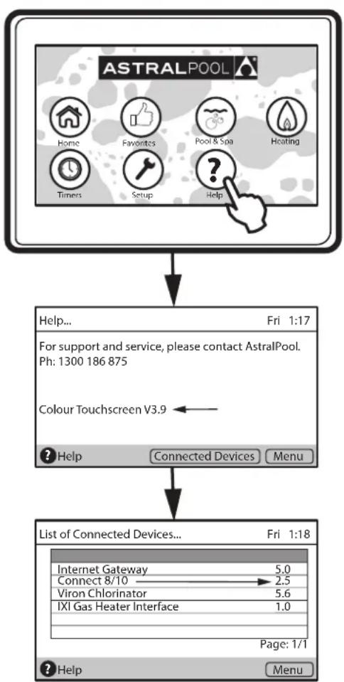
Note: The colour touchscreen must be revision 3.9 or greater.
The Connect10 button pcb must be revision be V2.2 or greater. This was introduced to production in November 2015.
flowchart
graph TD
    A["ASTRALPOOL"] --> B["Help... Fri 1:17"]
    B --> C["For support and service, please contact AstralPool. Ph: 1300 186 875"]
    C --> D["Colour Touchscreen V3.9 ←"]
    D --> E["? Help Connected Devices Menu"]
    E --> F["List of Connected Devices... Fri 1:18"]
    F --> G["Internet Gateway 5.0"]
    G --> H["Connect 8/10 → 2.5"]
    H --> I["Viron Chlorinator 5.6"]
    I --> J["IXI Gas Heater Interface 1.0"]
    J --> K["Page: 1/1"]
    K --> L["Help Menu"]
Figure 23. Viron Connect 10 Versions Check Process
To check system revision numbers on the touchscreen:
- Press Help to display the colour touch screen revision,
- Press the Connected Devices button to display the revisions of all connected devices. The Connect 10 button PCB revision number will appear as Connect 8/10 in the list.
Note: Connect 10 button PCBs that require updating must be completed by an authorized AstralPool representative. Only Colour touchscreens Revision 3 or above can be upgrade to revision 3.9. To download the firmware and view instructions, visit www.astralpool.com.au/connectmypool.
A Viron Connect 10 comes preconfigured to communicate with AstralPool-branded heaters in SYSTEM mode. If replacing a non-AstralPool branded
heater with an IXI gas heater for use with a Viron Connect 10, ensure the Connect 10 is in SYSTEM mode.
Note: The following steps are only required if replacing a non-AstralPool branded heater with an IXI gas heater for use with a Viron Connect 10.
This procedure is done by first turning power off to the unit, then take off the electrical cover panel to expose all wiring. Depending on the age of the Connect10, there may be two different ways to control system and local modes.
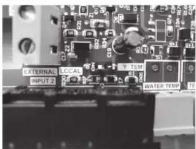
Dipswitch Version
If the Viron Connect10 uses a dipswitch to control, ensure the dipswitch is on Position 1.
SYSTEM
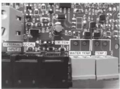
LOCAL
Bridging Pin Version
Locate the system/local pin configuration as shown below. Slide the plastic bridging pin to the middle/right position to enable SYSYEM MODE, if it not already set.
SYSTEM

LOCAL
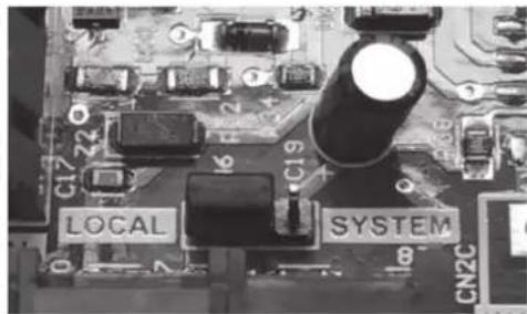
- Once an IXI Gas Heater interface has been connected to the Connect10, the heating icon will appear on the home screen. Press this to access heating controls.
- The current water temperature and the set temperature will be shown on the screen. If using pool and spa mode, different water temperature set points can be chosen for both.
- To adjust the set temperature, first select either pool or spa. Then using the up and down arrows to the right of the set temperature adjust to desired setting.
- Use the Heat ON/OFF button to operate your heater (water flow must be present before heater will function.
- For more information, refer to the Viron Connect10 user manual.
When the heater is connected to an external controller, all functionality of the heater control panel is disabled, therefore heater functions can be controlled only from the controller.
8.3.1 To Restore Heater Control Panel Functionality After Connecting To An External Controller
- Turn power to the heater ON. The heater display shows: ASTRALPOOL REMOTE ONLINE PUSH MENU TO DISABLE.
- Press MENU to remove message and restore functionality to the heater control panel.
8.3.2 To Return Control Back To A Connected External Controller
- Turn power to the heater OFF then back ON.
- Press and hold MENU for 5 seconds to access Setup Mode.
- Choose ASTRALPOOL REMOTE ONLINE.
Section 9. Final Installation Check
In order to ensure proper function and successful installation, it is required that the operation of the appliance be fully tested and confirmed. The following sections (9.1 - 9.7) address the initial start up and shut down of the heater. A successful initial startup test must be performed in order to complete the installation.
9.1 Operating Instructions
Follow the instructions outlined below to start the heater. Refer to the Lighting and Shutdown Instructions label on the inside lid panel of the heater. See Figure 24
All questions should be directed to technical support at 1300 186 875. Additional information can be found at www.AstralPool.com.au.

WARNING
If you do not follow the instructions below exactly, a fire or explosion may result, causing property damage, personal injury or loss of life.
9.2 Important Safety Information
1. Read Before You Start:
- This appliance does not have a pilot light. It is equipped with an ignition device, which automatically lights the heater. Do NOT try to light the burners by hand.
- BEFORE OPERATING, smell all around the appliance for gas. Be sure to smell next to the floor because some gas is heavier than air and will settle on the floor.
9.2.1 What To Do If You Smell Gas
- Do not try to light any appliance.
- Do not touch any electric switch; do not use any phone in your building.
- Immediately call your gas supplier from a neighbor's phone. Follow the gas supplier's instructions.
- If you cannot reach your gas supplier, call the Fire Department.
- Use only your hand to switch on or off the gas control switch. Never use tools. If the switch appears broken or will not move, don't try to repair it, call a qualified service technician. Force or attempted repair may result in fire or explosion.
- Do not use this appliance if any part has been under water. Immediately call a qualified service technician to inspect the appliance and to replace any part of the control system which has been under water.
9.3 First Time Start-up Procedure
WARNING
Vent pipes and heater tops get hot! These surfaces can cause serious burns. Do not touch these surfaces while the heater is in operation.
Do not use this heater if any part has been under water. Immediately call a qualified service technician to inspect the heater and replace any part of the control system and any gas control which has been under water.
Should overheating occur or the gas supply fail to shut off, turn off the manual gas control valve to the heater. Do not attempt repairs on the gas controls or appliance. Tampering is dangerous and voids all warranties
- Confirm that pool water is flowing normally through the pool system and equipment.
- If it is a new pool or spa installation, operate the filter pump with the heater off long enough to completely clean the water. This will remove any installation residue from the water.
- Clean the filter before starting the heater.
- Start the heater in either Pool or Spa mode. See Figure 24.
- Start the heater. See Figure 24.
- When the heater starts, confirm there is adequate water flow. See Section 5 for details.
9.4 Lighting Instructions
Refer to the Lighting and Shutdown Instructions. See Figure 24 located inside the top panel.
- STOP! Read IMPORTANT SAFETY INFORMATION in previous section.
- Set temperature thermostat controls to their lowest setting and turn off the controller. Make sure the display shows GAS HEATER IS OFF.
- Turn off all electrical power to the heater at the junction box.
- This appliance is equipped with an ignition device which automatically lights the heater. Do NOT try to light the burner by hand.
- Remove the heater rear or top panel.
- Unplug gas valve. See Figure 24.
- Wait five (5) minutes to clear out any gas, then smell for gas, including near the floor. IF YOU SMELL GAS, STOP! Follow instructions in Section 9.2.1.
- If no gas is detected, plug gas valve back in.
- Replace the rear panel and/or top.
- Turn on electrical power to the heater.
- Turn the controller ON by pressing POOL or SPA and set the temperatures as necessary.
NOTE: If the heater does not start, check that the filter pump is ON, the filter is clean and that water is flowing to the pool. If the heater still does not operate, follow the procedure in Section 8.4 to turn off gas supply to the heater.
If you do not follow these instructions exactly, a fire or explosion may result, causing property damage, personal injury, or death.
(A) This appliance does not have a pilot light. It is equipped with an ignition device which automatically lights the heater. Do NOT try to light the burners by hand.
(B) BEFORE OPERATING, smell all around the appliance for gas. Be sure to smell next to the floor because some gas is heavier than air and will settle on the floor.
WHAT TO DO IF YOU SMELL GAS
- Do not try to light any appliance.
- Do not touch any electric switch; do not use any phone in your building.
- Immediately call your gas supplier from a neighbor's phone. Follow the gas supplier's instructions.
- If you cannot reach your gas supplier, call the Fire Department.
(C) Use only your hand to activate the gas control switch. Never use tools. If the switch will not move by hand, do not try to repair it. Call a qualified service technician. Force or attempted repair may result in fire or explosion.
(D) Do not use this appliance if any part has been under water. Immediately call a qualified service technician to inspect the appliance and to replace any part of the control system which has been under water.
OPERATING INSTRUCTIONS
- STOP! Read the safety information above on this label.
2.* Set the thermostat to lowest setting and turn appliance switch to OFF. - Turn off all electric power to the appliance.
- This appliance is equipped with an ignition device which automatically lights the heater. Do not try to light the burners by hand.
- Remove the top panel.
- Tum gas control switch to OFF position
- Wait five (5) minutes to clear out any gas. Then smell for gas, including near the floor. If you smell gas, STOP! Follow "B" in the safety information above on this label. If you don't smell gas, go to next step.
-
Turn gas control switch to ON position.
-
Replace the top panel.
- Turn on all electric power to appliance.
11.* Set thermostat to desired setting and switch appliance from OFF to either POOL or SPA. - If the appliance will not operate, check that the filter pump is on, the filter is clean and water is flowing to the pool. Otherwise, follow the instructions "To Turn Gas Off" and call your service technician or gas supplier.

TO TURN GAS OFF
(1) Remove top panel.
(2) * Set the thermostat to lowest setting and switch appliance to OFF.
(3) Turn off all electrical power to the appliance if service is to be performed.
(4) Turn gas control switch to OFF position.
(5) Replace top panel.
* See manual for details of operation and thermostat control.
POUR VOTRE PROPRE SÉCURITÉ LISEZ CECI AVANT D'UTILISER LE CHAUFFE-EAU
AVERTISSEMENT
Figure 24. Lighting and Shutdown Instructions Label on Top Panel
WARNING
When the heater is fired for the first time, the combustion chamber refractory binder material is driven out by the heat of the flame. White smoke and/or sharp odors may be emitted from the vent during this period. Do not inhale combustion product fumes at any time, and especially when these fumes are being emitted. This "burn-in" period will last only a few minutes.
9.4.1 If Ignition Is Unsuccessful
If ignition is unsuccessful, or the flame fails during normal operation, the ignition control shuts off the gas valve. The heater will then go through a post purge process and attempt to establish stable combustion two additional times. If ignition is unsuccessful after three attempts, the system shuts down and will automatically attempt to restart after one hour.
- To reset the heater to provide three (3) attempts to start:
- Turn OFF the control then turn it back ON.
- Access either the Pool or Spa mode.
9.5 To Turn Off Gas To The Heater
- Set temperature thermostat controls to their lowest setting and turn off the controller. Make sure the display shows GAS HEATER IS OFF.
- Turn off all electrical power to the heater at the junction box.
- Remove the rear panel or top.
- Disconnect power connection to the gas valve by unplugging the power supply plug from the gas valve body.
- Shut off the external gas supply valve to the heater.
- Replace the rear panel or top.

9.6 Normal Operation
During normal operation, the control system measures the temperature of the water flowing through the heater and will begin the start-up process if the temperature is below the set point. If the blower pressure switch senses adequate airflow when the blower starts, the ignition sequence begins. Following a pre purge, the igniter is energized, then the gas valve opens. As long as a flame is sensed at the burner, operation continues until the temperature of the water entering the heater reaches the temperature control setting.
9.7 Operating The Controller
Unless the heater is connected to a remote controller, all operations are set up and programmed through the control panel on the top of the heater. See Figure 25.
NOTE: The display light reverts to OFF after two minutes of inactivity since the last key was pressed.
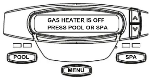
Figure 25. Main Control Panel
9.7.1 Setting Up Heater Options
The IXI gas heater's function are controlled via the user controls at the front of the unit. In addition to the buttons, the system menus are shown in the small screen with selections chosen by the Up and Down buttons.
9.7.2 Operating The Heater
Before using the heater for the first time, set up the following options:
• Languages: Set a display language
- Temperature Scale: Set temperatures to be displayed in either Celsius or Fahrenheit scale
- Display Light Timeout: Set the display light to turn off after a specific interval of inactivity
• To Program the Display Language

flowchart
graph TD
    A["MENU"] --> B["or"]
    B --> C["SELECT USER SETUP LANGUAGE"]
    D["MENU"] --> E["OR"]
    E --> F["SELECT LANGUAGE ENGLISH"]
    G["MENU"] --> H["To Save"]
    H --> I["POOL or SPA To Exit"]
• To Program the Temperature Scale (F or C)

flowchart
graph TD
    A["MENU"] --> B["Select USER SETUP TEMPERATURE SCALE"]
    C["or"] --> B
    D["MENU"] --> E["SELECT TEMP SCALE °C"]
    F["or to Toggle °F and °C"] --> E
    G["MENU"] --> H["To Save"]
    I["POOL"] --> H
    J["or To Beat"] --> H
    B --> K["Hold for 5 Seconds."]
    E --> L["Select TEMP SCALE °C"]
• To Program Display Light to Turn Off Automatically

flowchart
graph TD
    A["MENU"] --> B["or"]
    B --> C["SELECT USER SETUP DISPLAY LIGHT"]
    D["MENU"] --> E["or to Toggle"]
    E --> F["To Save"]
    G["POOL"] --> H["or To Exit"]
    I["Select DISPLAY LIGHT 2 MIN TIMEOUT"] --> J["Select User Setup Display Light"]
9.7.3 Operating The Heater
• To Turn on Pool or Spa Heat

flowchart
graph TD
    A["POOL or SPA"] --> B["SET: 27°C"]
    C["To Change Temperature Set Point"] --> D["Current temp displayed"]
    style A fill:#f9f,stroke:#333
    style B fill:#ccf,stroke:#333
    style C fill:#cfc,stroke:#333
    style D fill:#fcc,stroke:#333
- To Maintain Pool or Spa Heat (optional Relay and Wiring Required)

flowchart
graph TD
    A["POOL or SPA"] --> B["SET: 27°C"]
    C["MENU"] --> D["MAINTAIN POOL HEAT or MAINTAIN SPA HEAT"]
    E["MENU"] --> F["SET: 27°C"]
    G["To Change Temperature Set Point"] --> H["After 5 seconds of inactivity, new temp is stored as the set point."]
If connected, the Maintain Heat mode monitors the pool water temperature 24 hours a day by turning the pool pump on and sampling the water temperature. When the water temperature drops below the programmed temperature set point, the controller automatically starts heating the pool.
• To Turn the Heater Off
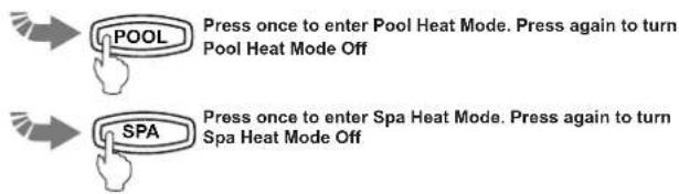
When the control panel is OFF, the screen displays: GAS HEATER IS OFF PRESS POOL OR SPA.
• Temperature Set Point Lock
Once you have programmed pool temperature and spa temperature set points, you can lock them so that they may not be changed inadvertently.

flowchart
graph TD
    A["POOL"] --> B["or SPA"]
    B --> C["SET: 27°C"]
    D["Press both Keys at same time.<br>Hold for 7 seconds"] --> E["SET POINT LOCKED<br>SET POINT UNLOCKED"]
    E --> F["Lock or unlock depending"]
9.8 Shutting Down The Heater
Complete shutdown instructions are as follows. Refer to Figure 18.
- Set temperature thermostat controls to their lowest setting and turn off the controller. Make sure the display shows OFF.
- Turn off all electrical power to the heater at the junction box.
- Remove the top panel of the heater.
- Unplug the gas valve.
- Shut off the external gas supply valve to the heater.
- Replace the top panel.
Section 10. Maintenance
If the heater is not going to be used for an extended period of time and in colder climates, shut it down completely. See Section 9.8 and Figure 24.
IMPORTANT MAINTENANCE NOTE
We recommend that before each pool season, the Thermal Regulator Valve (TRV) be inspected for proper operation and replaced if there are signs of scaling or corrosion.
Corrosion and scaling are the result of improperly balanced water please see Section 9.1.1 for complete details on managing your water chemistry.
The TRV ensures the heater operates at its optimal efficiency and if properly maintained will extend the life of the heater.
WARNING
Do not operate the heater if the water temperature is below 40^ F ( 4^ C)
- Short term operation of heater when temps are below 40F can continue but continuous flow must be maintained.
- Prolonged operation with water below 50F can seriously damage the heater and is not covered by warranty.
10.1 Water Chemistry
Proper Water Balance is the key to the enjoyment of your pool or spa experience and to the long life of your heater.
The pH of your pool or spa's water is one of the factors that has the most impact on indicating how properly balanced the water is. The other factors are: temperature, total alkalinity, calcium hardness and total dissolved solids. Cold water is typically more acidic (corrosive), while hot water tends to lead to a scale forming (basic) condition. While the heater is in operation, if the PH is allowed to rise above 7.8 and the calcium hardness and total alkalinity are not properly maintained; calcium in the water could lose solubility, coating the copper tubes inside the heat exchanger. This will restrict the flow of water resulting in reduced efficiency and possible damage to the heater.
If the pH is allowed to drop below 7.2, and the alkalinity is not properly maintained, the water will become more acidic. Acidic water has a tendency to dissolve metal components in the pool plumbing such as copper tubing in the heat exchanger.
| Recommended Levels | Fiberglass Pools | Fiberglass Spas | Other Pool and Spa Types |
| Water Temperature | 20-31 °C (66-88 °F) | 31-40 °C (89-104 °F) | 20-40 °C (68-104 °F) |
| pH | 7.3 - 7.4 | 7.3 - 7.4 | 7.6 - 7.8 |
| Total Alkalinity (ppm) | 120 - 150 | 120 - 150 | 80 - 120 |
| Calcium Hardness (ppm) | 200 - 300 | 150 - 200 | 200 - 400 |
| Salt (ppm) | 4500 Maximum | 4500 Maximum | 4500 Maximum |
| Free Chlorine (ppm)* | 2 - 3 | 2 - 3 | 2 - 3 |
| Total Dissolved Solids (ppm) | 3000 Maximum** | 3000 Maximum** | 3000 Maximum** |
| *Free Chlorine MUST NOT EXCEED 5 ppm!.**In saltwater chlorinated pools, the total TDS can be as high as 6000 ppm. | |||
Table 5. Pool Water Chemistry
10.2 Saturation Index
| Saturation Index = pH + AF + CF + TF -12.1*A-Factor=(AF), C-Factor=(CF), T-Factor=(TF) | |||||
| Total Alkalinity | Calcium Hardness Temperature | ||||
| A-Factor C-Factor T-Factor | |||||
| PPM | Factor Value | PPM | Factor Value | °C | Factor Value |
| 5 = 0.7 5 = 0.9 0 = 0.0 | 0.0 | ||||
| 25 = 1.4 25 = 1.0 3 = 0.1 | 0.1 | ||||
| 50 = 1.7 50 = 1.3 8 = 0.2 | 0.2 | ||||
| 75 = 1.9 75 = 1.5 | 12 = 0.3 | ||||
| 100 = 2.0 | 100 = 1.6 | 16 = 0.4 | |||
| 150 = 2.2 | 150 = 1.8 | 19 = 0.5 | |||
| 200 = 2.3 | 200 = 1.9 | 24 = 0.6 | |||
| 300 = 2.5 | 300 = 2.1 | 29 = 0.7 | |||
| 400 = 2.6 | 400 = 2.2 | 34 = 0.8 | |||
| 800 = 2.9 | 800 = 2.5 | 41 = 0.9 | |||
| A saturation index of 0 is perfectly balancedA negative saturation index has corrosive tendenciesA positive saturation index has scaling tendenciesA saturation index of +0.3 or -0.3 is ideal*-12.1 should be changed to -12.2 if Total Dissolved Solids (TDS)measure at 1,000 ppm or greater | |||||
Table 6. Water Saturation Index
PH, Total Alkalinity (TA), temperature, Calcium Hardness and Total Dissolved Solids (TDS) play a role in whether the water is either corrosive or scale forming. These factors are combined in the Langelier Saturation Index, which is a method for determining whether or not water is properly balanced. See Table 6.
The practice of putting tablet-based sanitizer in the skimmer basket can produce heavily chlorinated water with very low pH. If this comes in contact with metal parts of the heater it can cause serious damage. Practices like this should be discontinued.
If acidic conditions are present, there could be signs of metal in the pool water that could cause staining on the floor of your pool. This might manifest itself in the form of brown stains on the finish of your pool bottom
or pool water discoloration. Your local pool dealer can test for metals in your water or can provide you with a test kit.
Every effort should be made to maintain the water balance of your pool or spa in the proper range. Ignoring this very important component of your pool's water chemistry can make the water less enjoyable to bathe in and result in permanent damage to your heater and/or complete failure of individual components.
AstralPool does not warrant heat exchangers damaged by corrosive water issues or from the build-up of calcium in the heater's heat exchanger. Any questions regarding proper water balance can be directed to our product support line at AstralPool® or to your local pool dealer.
NOTE: The Thermal Regulator Valve (TRV) is an indicator of how well the water balance is being maintained. The TRV should be inspected before each pool season to ensure it is clean and operating properly. If you see signs of calcium buildup (scale-forming or base water) or corrosion (acidic water) the TRV should be replaced and your water balanced. See Section 13.4 for image.
10.3 Swimming Pool Energy Saving Tips
Please review the following recommendations to help conserve fuel and minimize the cost of operating your pool heater without sacrificing comfort.
- The recommended maximum water temperature is 26 °C (79 °F). Use an accurate pool thermometer. A difference of 2 °C (3 °F), between 26 °C (79 °F) and 28 °C (82 °F), will use as much as 40% more gas.
- Carefully monitor the water temperature of your pool in the summertime. You can reduce heater usage due to warmer air temperatures.
- Find the proper setting on the pool heater temperature control and use the Set Point Lockout feature to discourage further adjustments.
-
Set the pump time clock to start the pump no earlier than 6:00 AM. This is the time when nightly heat loss balances.
-
If the pool is only going to be used on weekends, reduce the heater temperature control setting by 4 or 6 degrees during the week. Reset it to the 26^ (79^) level a day or so before you plan to use the pool.
- During the winter or when on vacation for longer than a week, shut down the heater by following the shutdown instructions found in Section 9.8 and Figure 24. and on the inside of the heater.
- Where possible, shelter the pool from prevailing winds with well-trimmed hedges or other landscaping, cabanas, or fencing.
- The greatest source of heat loss in a swimming pool is through evaporation. It can accounts for 50% of pool systems total heat loss. The use of solar blankets, automatic covers or anything that limits the air's access to the surface of the water will help reduce this heat loss and minimize evaporation.
10.4 Winterizing
In areas where freezing temperatures occur in winter and the pool or spa will not be used, the pool should be winterized by a qualified pool service technician:
- Turn off the electrical supply and the main gas supply to the heater.
- Remove the heater access panel.
- Turn off gas supply to the heater following the shut-down instructions. See Section 9.8 and Figure 24.
- Remove the drain plug from the inlet/outlet header and completely drain the heater before the first frost.
- Inspect the gasket on the drain plug. Store the drain plug in a safe place for winter.
- Cover the exhaust vent grill with plastic so that snow will not accumulate and freeze on top of the combustion chamber.
- Remove and drain the copper tubing for the water pressure switch.

Figure 26. Water Pressure Switch Copper Tubing (Siphon Loop)
10.5 Spring Start-up
When winterized, the heater should be reassembled by a qualified professional technician in the Spring.
- Reinstall the drain plug.
• Uncover the vent grill. - Reattach copper tubing to water pressure switch.
- Make sure power is supplied to the pump.
- Turn on the filter pump and circulate water through the heater for 5 minutes. Check for leaks while circulating.
- Turn on the main gas supply to the heater at the gas cock outside the heater jacket.
- Turn on the heater according to Section 9.4 and Figure 24.
10.6 Inspection and Service
WARNING
Improper installation or maintenance can cause nausea or asphyxiation from carbon monoxide in flue gases which could result in severe injury, or death.
The heater is designed and constructed to provide long performance life when installed and operated properly under normal conditions. Periodic inspections, especially at spring start-up, are important to keep your heater running safely and efficiently through the years. AstralPool recommends that the homeowner inspect the heater on a regular basis (especially after abnormal weather conditions), and arrange to have a professional inspection at least once a year by a qualified service technician.
WARNING
For your safety, when starting the heater, keep your head and face away from the exhaust grill opening and blower inlet grill to prevent any risk of personal injury. Make sure all doors/panels are securely in place and stand back from the heater.
10.6.1 Guidelines For Homeowner Inspections
WARNING
Do not store or use gasoline or other flammable vapors, liquids or chemicals in the vicinity of this or any other appliance.
WARNING
Do not use this heater if any part has been under water. Immediately call a qualified service technician to inspect the heater and replace any part of the control system and any gas control which has been under water.
- Keep the top of the heater, under the heater, and surrounding area clear of all debris and combustible materials such as paper, leaves, etc.
-
If there is a pressure relief valve, check for corrosion in and around the valve. If there is corrosion, turn off the filter pump and replace the pressure relief valve.
-
Once a year check that water is running freely through the pressure relief valve. To check, turn on the filter pump and lift the release lever on the top of the valve.
- Be sure combustion air and ventilation openings are not blocked.
10.6.2 Guidelines For Professional Inspections
The following inspections should be made once a year or as needed. Routine inspections are a critical to the safety and long life of your AstralPool pool equipment.
- Check for loose or broken wires and terminal connections.
- Check the water pressure switch by turning the filter pump off and on several times. The burner should go off immediately after the pump stops. The fan run for 45 seconds after the burner shuts down.
CAUTION
If the heater is wired serially to or on the same relay as the fi Iter pump, there is a chance that power will be disconnected to the heater before the fan is able to fully purge the combustion chamber. It is inadvisable to install the heater in a manner which would prevent this combustion chamber purge from taking place.
- An ignition sequence should start shortly after the pump is turned back on.
• Inspection the thermal regulator valve (TRV). - Inspect the electrical controls, specifically:
a. High limit switches.
b. Water pressure switch.
c. Automatic gas valve.
d. Power interface/Temperature control.
e. Flue temperature sensor.
f. Control circuit fuse.
g. Ignition control.
h. Air pressure switch. - Inspect the inlet grill at the blower for blockage, leakage, and corrosion.
- Inspect the combustion blower for damage.
- Conduct a normal operating cycle and observe that the sequence proceeds as intended.
- If the heater is equipped with a pressure relief valve, clean any accumulated corrosion and make sure that water runs freely when lever is lifted.
- Inspect the outside of the combustion chamber and blower for corrosion and indication of improper operation.
- Inspect electrical controls for deterioration. Repair and replace as necessary.
- Visually check the main burner flame. Remove the top of the heater to inspect the sight glass. See
Figure 27

Figure 27. Remove Heater Top to View Sight Glass
Section 11. Troubleshooting
11.1 Common Problems
AstralPool strongly recommends that you call a qualified service technician to perform all service and repairs on the heater. To locate a licensed or qualified technician service company, call AstralPool, 1300 186 875, or visit www.AstralPool.com.au.
The following table lists some of the most common problems when running the heater. Most problems occur when the heater is started for the first time after installation or at spring start-up.
| Symptom Possible Cause Remedy | ||
| Pump not operating • No power. | • Check circuit breakers and power source.• Replace the pump.• Recheck wiring.• Check time clock setting. | |
| • Pump defective.• Incorrectly wired.• Time clock settings not synchronized with actual time. | ||
| Unstable combustion-(1) heater turns off and on(2) heater ignites slowly(3) flame lifts and goes out(4) short yellow streaked flame | • Wrong gas.• Lean fuel/air mixture— low supply pressure.• Lean fuel/air mixture— too much combustion air.• Rich fuel/air mixture— high manifold pressure.• Rich fuel/air mixture— too little combustion air. | • Make sure the gas supply matches the gas type indicated on the rating plate.• Correct gas supply inlet pressure to:- NATURAL GAS - 1.13 kPa (4.5" W.C.) min - 2.6 kPa (10.5" W.C.) max- ULPG - 1.13 kPa (4.5" W.C.) min - 3.5 kPa (14.0" W.C.) max• Offset pressure should be -.05 kPa (-0.2" W.C.) Use a digital differential manometer to verify correct offset pressure. Adjust offset pressure as needed.See Section 5.2• Connect a digital differential manometer to blower throat and gas valve port to obtain differential. Make sure the differential value falls within the specified range for the heater size. See Section 5.1• Gas meter too small.• Gas line from meter to heater too small.• Check blower inlet grill for obstruction. |
| Not enough heat(1) heater is slow to heat up(2) heater not maintaining set temperature(3) Low temperature rise | • Heater size inadequate.• Filter pump not running long enough.• Thermal regulator valve (TRV) is opening early or is permanently open.• Heater plumbed backwards. | • Replace with heater of higher output.• Replace TRV.• Heater is condensing. Flue product moisture will condense at the start-up until the heater water temperature reaches the normal operating conditions.• Correct the plumbing. |
| Heater pounding or knocking • | Water flow through heater too low.• Failed Thermal Regulating Valve (TRV). | • Look for obstruction or closed valve in system.• Check for damaged internal bypass.• Variable speed pump set too low.• Dirty filter or baskets. |
| Igniter lights but heater does not fire | • Gas valve is not ON.• Air in gas line.• No power to gas valve.• Low gas pressure/volume.• High burner throat pressure.• Gas valve failed. | • Cycle ignition sequence until air is out of the gas line.• Check controls for proper operation.• Check supply pressure/volume and verify proper gas supply pipe size.• Replace gas valve.NOTE: Gas valve failures are extremely rare. Please confirm this as the root problem before replacing. |
11.2 Service Diagnostic Messages
The controller monitors several functions of the heater. In the event of a malfunction, the controller will display a FAULT message. The following table lists the Heater Service Messages along with potential causes and remedies.
| Fault Message Possible Cause Remedy | ||
| CHECK FLOW | Pump is not running.Low pump pressure.Pressure switch fault.Variable speed pump set too low. | Check breakers and power source, recheck wiring, set time clock and current time.Clean filter or clear blockage, check position of valve in plumbing system.Make sure return eyeball fittings are installed on the wall of the poolAdjust or replace pressure switch.Adjust variable speed pump.Refer to qualified service personnel. |
| FAULT-HIGH LIMIT | Water temperature in heater exceeds the internal limit.Limit switch fault. | Inspect vent for obstructions or blockages.Indoor installations, check vent pipe for bird, insect or rodent activity that could cause a blockage.Replace switches.Refer to qualified service personnel. |
| FAULT - HIGH FLUE TEMPERATURE | Flue temp limit fault·Identify and correct loose connections. | Replace flue sensor.Refer to qualified service personnel. |
| FAULT-CHECK IGN CONTROL | Broken, split, pinched or disconnected air pressure switch tubing.Fan not operating.Fan running slow or premature fan failure.Air flow restricted at intake or discharge.Broken igniter.Low gas supply pressure/volume.No flame at burner. | Check tubing and replace if necessary.Correct fault or replace fan.Replace igniter.Verify proper wiring for 230 VAC.Check for proper clearances around heater and for adequate room ventilation if enclosed. Inspect for blockage or restriction at discharge of flue.Check ignition control LED codes (see Section 9.3, Ignition Control LED Service Codes).Verify that the size, length and number of elbows on the gas supply line meet national codes.Identify and correct loose wiring connections, or problems with igniter, gas valve, or ignition control.Refer to qualified service personnel. |
| FAULT-SHORTED H2O SENSOR or FAULT-OPEN WATER SENSOR | Faulty wiring or connection.Failured water temperature sensor. | Inspect water temperature sensor wiring.Ensure sensor is connected correctly into the power interface board (PIB).Replace water temperature sensor.Refer to qualified service personnel. |
| FAULT-PUMP | Status message indicating the filter pump is currently turned OFF when the heater system programmed in Maintain Temp mode. | No Service Required. This is normal when the control is in a Maintain Temp mode. |
11.3 Ignition Control Service LED Codes
In addition to service diagnostic messages, the ignition controller has an LED light that flashes to indicate various ignition control faults. The following table lists the LED codes and the corresponding fault description. To diagnose possible cause and remedy, refer to Section 11.2, Service Diagnostic Messages.
| LED Code Fault Description | |
| The LED light is on continuously. Ignition Control Fault. Refer to qualified service personnel. | |
| LED single flash. Air flow fault. | |
| LED double flash. Flame exists when there is NO call for heat. Refer to qualified service personnel. | |
| LED triple flash. | Ignition lockout (heater has made three (3) unsuccessful attempts to fire and is in a soft lockout condition). |
Section 12. Professional Service and Maintenance
AstralPool strongly recommends that you call a qualified service technician to perform all service and repairs on the heater. To locate a licensed or qualified technician or independent service company in your area, contact AstralPool Technical Support at:
1300 186 875
www.AstralPool.com.au
Before servicing the heater:
- Confirm that the heater control is set to either POOL or SPA
- Confirm the temperature set point for either Pool or Spa is set high enough to make the heater operate given the current water temperature.
WARNING
SERVICING SAFETY
Service procedures can be hazardous because they involve fuel gas, electricity, moving parts and procedures which require testing or temporary bypass of safety controls. For this reason, the heater must be serviced only by a qualified professional service technician.
IMPROPER SERVICE HAZARD
The heater incorporates unique design features. Incorrect service of this heater can result in personal injury or damage to property. To avoid such hazards, the heater must be serviced only by a qualified professional service technician.
12.1 Header Bypass Reassembly Recommendations
If you need to remove the access cover or the VersaFlo housing from the header, use the following torque process to re-install them to the header. Start each screw by hand and then follow the torque pattern detailed below.

Figure 28. Header Bypass Reassembly Torque Pattern
Section 13. Spare Parts
Using genuine AstralPool factory replacement parts helps to ensure the ongoing quality and reliability of our products.
Unauthentic parts might seem okay on the surface, but they often fall short of factory standards, and they typically lack the backing you get from an established, global manufacturer like AstralPool. Plus, the use of unauthentic parts voids all factory warranties.
AstralPool does not sell parts directly to pool owners, so when it's time for maintenance, please see your local AstralPool stockist for genuine parts. You can find a dealer here at www.AstralPool.com.au/find-a-dealer.
NOTE: To identify the correct part, you will need to know the model number, serial number and type of gas when applicable. This information can be found on the rating plate sticker, which is located inside the heater on the outside of the combustion chamber.
13.1 Major Components
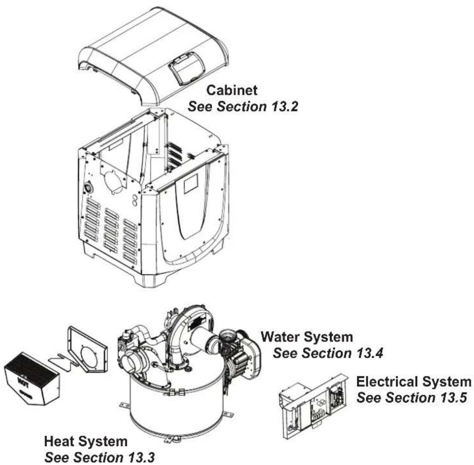
13.2 Cabinet Assembly Spare Parts List and Exploded Parts Diagram
| Key No Description model 200 model 370 | |||
| 1 Heater Jacket Top Kit (no User Interface) R0592400 R0592400 | |||
| 2 Corner Post Kit, Left/Right (set of 2) R0592500 R0592500 | |||
| 3 Heater Base Kit R0592600 R0592600 | |||
| 4 Front or Back Panel Kit R0592701 R0592701 | |||
| 5 Side Panel Kit R0592901 R0592901 | |||
| 6 Vent Terminal Housing Kit | R0593100 R0593100 | ||
| 7 Jacket Hardware Kit(speed nuts, screws, jacket clips) | R0593300 R0593300 | ||
| 8 Anchor Brackets Kit (set of 4) | R0593400 R0593400 | ||
| 9 Jacket Hole Plug Kit | R0591800 R0591800 | ||
| 10* | Complete Replacement Box Packaging Kit | R0593601 R0593601 | |
* Not Shown
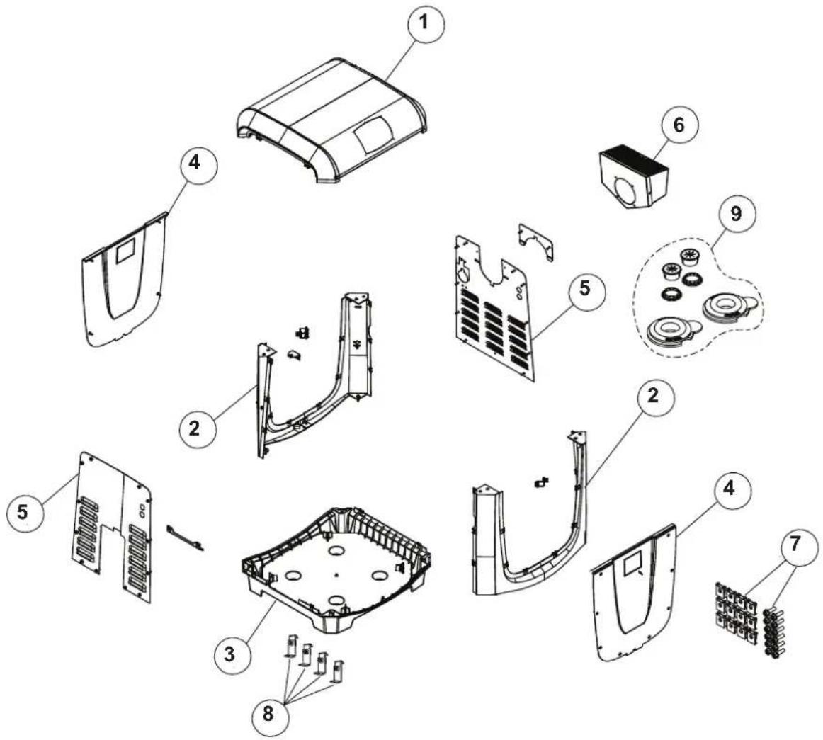
13.3 Heat System Spare Parts List and Exploded Parts Diagram
13.3.1 Combustion Chamber Assembly
| Key No* Description model 200 model 370 | |||
| 1 Exhaust Elbow Assembly Kit R0590200 R0590200 | |||
| 2 Band Clamp Kit R0590400 R0590400 | |||
| 3 Refractory Kit, Internal R0590500 R0590500 | |||
| 4 Combustion Chamber Shelf R0590701 N/A | |||
| 5 Combustion Chamber Lid Kit | R0590800 R0590800 | ||
| 6 Gasket Kit | R0590901 R0590901 | ||
| 7 Sight Glass Kit | R0305400 R0305400 | ||
| 8 Ignitor Kit | R0457502 R0457502 | ||
| 9 Insulation Kit, External R0591000 R0591000 | |||
| 10 | Isolator Kit (Thermal) | R0593200 R0593200 | |
| 11 | Heat Exchange Assembly | R0589402 R0589405 | |

13.3.2 Burner Assembly
| Key No | Description model 200 model 370 | ||||
| *N **ULPG N ULPG | |||||
| 1 Blower Assembly Kit | R0591100 R059 | 1100 R0591100 | R0591100 | ||
| 2 Air Intake Grate Kit | R0591200 R059 | 1200 R0591200 | R0591200 | ||
| 3 Blower Intake Orifice Kit | R0734101 R073 | 4101 R0734102 | R0734102 | ||
| 4 Gas Valve | R0739300 R073 | 9300 R0739300 | R0739300 | ||
| 5 Burner Kit | R0591702 R059 | 1702 R0591705 | R0591705 | ||
| 6 Direct Air Intake Kit | R0724600 R072 | 4600 R0724600 | R0724600 | ||
| 7 Capacitor Kit | R0614500 R061 | 4500 R0614500 | R0614500 | ||
* N - Natural Gas; **ULPG - Universal LPG

13.4 Water System Spare Parts List and Exploded Parts Diagram
| Key No Description model 200 model 370 | |||
| 1 Access | Door Kit R0589600 R0589600 | ||
| 2 Thermal | Regulator Valve Kit (TRV) R0589700 R0589700 | ||
| 3 Bypass | Kit R0589800 R0589800 | ||
| 4 Drain Plug | Kit R0446000 R0446000 | ||
| 5 Gasket and Seals Kit | R0589500 R0589500 | ||
| 6 Manifold | Backplate Kit R0590002 R0590005 | ||
| 7 Manifold, 3 Port (no backplate included; must order separately) | R0590101 R0590101 | ||
| 8 Water Pressure Switch Kit | R0457002 R0457002 | ||
| 9 Goody Bag Kit + | R0593500 R0593500 | ||
| 10 | Universal Half Union Kit (1 Ea, requires 2 kits for full unit replacement) | R0522900 | R0522900 |
| 11 | Sweep Elbow Aqualink* Temp Sensor | SEAQL1001 | SEAQL1001 |
| 12 | Drain Cap Assembly Kit | R0523000 R0523000 | |
| 13 | Flow Plate Assembly | R0725201 R0725203 | |
† Goody Bag Kit Also Includes the Installation and Operation Manual and the Universal Controller Quick Guide

13.5 Electrical System Spare Parts List and Exploded Parts Diagram
| Key No Description model 200 model 370 | |||
| 1 Ignit | on Control Kit R0456901 R0456901 | ||
| 2 Transformer Kit R0456301 R0456301 | |||
| 3 User | Interface Kit R0591901 R0591901 | ||
| 4 User | Interface Lid Kit R0592001 R0592001 | ||
| 5 Wiring Harness Kit R0592102 R0592102 | |||
| 6 Air Pressure Switch Kit | R0456400 R0456400 | ||
| 7 | Flue Temp Sensor | R0719401 | R0719401 |
| 8 7 PSI | Water Pressure Switch Kit | R0013204 R0013204 | |
| 9 Power Interface Board (PIB) | R0719503 R0719503 | ||
| 10 | Power Distribution Board (PDB) | R0458101 R0458101 | |
| 11 | Temperature Sensor Kit | R0456500 R0456500 | |
| 12a | High Limit Temperature Sensors Kit (For Header Type “A”) | R0592301 | R0592301 |
| 12b | High Limit Temperature Sensors Kit (For Header Type “B”) | R0592302 | R0592302 |
| 13 | Igniter Kit | R0457502 R0457502 | |
| 14 | Power Interface Harness | R0457702 R0457702 | |

* Items not shown in illustration:
• Power interface, controller harness w/bypass
• Universal controller main reset, rollout switch harness
- User interface, universal controller harness 4

For AU
For full warranty terms and conditions and to register your warranty, simply visit www.astralpool.com.au/warranty or www.astralpool.com.nz/warranty and complete your details. Or scan the QR code and be taken directly to the registration page.
Record your equipment details here for quick reference:
Model No.: ____

For NZ
Serial No.: ____

H0750200



- IXI GAS POOL AND SPA HEATER
- WARNING
- TABLE OF CONTENTS
- Section 1. Important Safety Instructions .... 4
- Section 2. General Information......6
- Section 3. Getting Started....9
- Section 4. Location Requirements......10
- Section 5. Gas Connections ....16
- Section 6. Water Connections....19
- Section 7. Electrical Connections....25
- Section 8. Optional Remote Controls......27
- Section 9. Final Installation Check....31
- Section 10. Maintenance....35
- Section 11. Troubleshooting....39
- Section 12. Professional Service and Maintenance....41
- Section 13. Spare Parts....42
- Section 1. Important Safety Instructions
- READ AND FOLLOW ALL INSTRUCTIONS
- DANGER
- To Reduce the Risk of Injury -
- Section 2. General Information
- Technical Assistance
- Warranty
- Consumer Information and Safety
- General Operation Description
- Specifications
- Dimensions
- Certification Codes and Standards
- HeaterComponents
- Section 3. Getting Started
- Contents
- Required Equipment
- Required Tools
- Materials Supplied by Installer
- Section 4. Location Requirements
- CAUTION
- Clearances
- OutdoorInstallation
- Locate the heater:
- Indoor and Outdoor Shelter Installation
- Combustion Intake Air Supply
- Direct Air Intake
- ExhaustVenting
- Indoor and Outdoor Shelter Exhaust Conversion
- Precautions Against Common Venting
- Inspection and Replacement of Existing Vent System With New Components
- Section 5. Gas Connections
- Supply Gas Requirements
- ATTENTION
- Inlet Gas Pressure Test
- Table 3. Supply Gas Input Pressure Requirements
- Special Precautions for ULPG Gas
- Section 6. WaterConnections
- PumpSizing
- Manual Bypass Valve
- Pump Sizing for New Pool Construction
- Pump Sizing for Replacement in an Existing Pool
- Plumbing Connections
- Reverse Plumbing Connection
- Water Inlet Piping
- Water Pressure Switch Adjustment
- Check Valve Installation
- Pressure Relief Valve (PRV) Installation
- Header Type "A" (PRV) Installation
- Header Type "B" (PRV) Installation (not provided by AstralPool)
- Auxiliary Components, Chlorinators, Ozone Generators and Sanitizing Chemicals
- Section 7. Electrical Connections
- ServiceAccess
- Bonding
- Section 8. Optional Remote Controls
- Connecting to a Remote Pool-Off-Spa Selector (3-Wire Connection)
- Configure the Control Panel
- Connecting to a Remote TSTAT (2-Wire Connection)/AstralPool Intelli-Heat Controller
- Installing the Remote TSTAT/AstralPool Intelli-Heat Connection
- Configure the Control Panel
- Connect To A Viron Connect or "Smart" Communication Via RS-485
- Installing the IXI Interface Controller for use with AstralPool Connect 10 Systems
- Connect 10 Touchscreen Setup
- Dipswitch Version
- Bridging Pin Version
- To Restore Heater Control Panel Functionality After Connecting To An External Controller
- To Return Control Back To A Connected External Controller
- Section 9. Final Installation Check
- Operating Instructions
- Important Safety Information
- Read Before You Start:
- What To Do If You Smell Gas
- First Time Start-up Procedure
- Lighting Instructions
- WHAT TO DO IF YOU SMELL GAS
- OPERATING INSTRUCTIONS
- TO TURN GAS OFF
- POUR VOTRE PROPRE SÉCURITÉ LISEZ CECI AVANT D'UTILISER LE CHAUFFE-EAU
- AVERTISSEMENT
- If Ignition Is Unsuccessful
- To Turn Off Gas To The Heater
- Normal Operation
- Operating The Controller
- Setting Up Heater Options
- Operating The Heater
- • To Program the Display Language
- • To Program the Temperature Scale (F or C)
- • To Program Display Light to Turn Off Automatically
- Operating The Heater
- • To Turn on Pool or Spa Heat
- - To Maintain Pool or Spa Heat (optional Relay and Wiring Required)
- • To Turn the Heater Off
- • Temperature Set Point Lock
- Shutting Down The Heater
- Section 10. Maintenance
- IMPORTANT MAINTENANCE NOTE
- Water Chemistry
- Saturation Index
- Swimming Pool Energy Saving Tips
- Winterizing
- Spring Start-up
- Inspection and Service
- Guidelines For Homeowner Inspections
- Guidelines For Professional Inspections
- Section 11. Troubleshooting
- Common Problems
- Service Diagnostic Messages
- Ignition Control Service LED Codes
- Section 12. Professional Service and Maintenance
- Before servicing the heater:
- SERVICING SAFETY
- IMPROPER SERVICE HAZARD
- Header Bypass Reassembly Recommendations
- Section 13. Spare Parts
- Cabinet Assembly Spare Parts List and Exploded Parts Diagram
- Heat System Spare Parts List and Exploded Parts Diagram
- Combustion Chamber Assembly
- Burner Assembly
- Water System Spare Parts List and Exploded Parts Diagram
- Electrical System Spare Parts List and Exploded Parts Diagram
Brand : ASTRALPOOL
Model : IXI 200
Category : Heating