
Viron Inverter iHP90 - Heating ASTRALPOOL - Free user manual and instructions
Find the device manual for free Viron Inverter iHP90 ASTRALPOOL in PDF.


| Product Type | Inverter Pool Heat Pump |
| Model | Viron Inverter iHP90 |
| Brand | AstralPool |
| Heating Capacity | 9.0 kW (approx. 30,700 BTU/h) |
| COP (Coefficient of Performance) | Up to 5.5 at ambient 26°C / water 26°C |
| Operating Air Temperature Range | -5°C to 43°C |
| Refrigerant | R32 |
| Power Supply | 230V / 50Hz / 1-Phase |
| Rated Power Input | 1.8 kW |
| Max Current | 8.5 A |
| Water Flow Rate (min/max) | 3.5 / 7.5 m³/h |
| Water Connection Diameter | 50 mm (2") |
| Dimensions (L x W x H) | 1010 x 420 x 650 mm |
| Weight (net) | 52 kg |
| Sound Level at 1m | ≤ 55 dB(A) |
| Display | Multilingual LED display with touch buttons |
| Control Features | Inverter compressor, timer, frost protection, anti-corrosion coating |
| Installation | Outdoor, on stable level surface, free from obstructions |
| Maintenance | Regular cleaning of air filter and evaporator, check water filter |
| Safety Protection | Overheating, overcurrent, refrigerant leak detection, high/low pressure |
| Spare Parts Availability | Through AstralPool authorized service centers |
Frequently Asked Questions - Viron Inverter iHP90 ASTRALPOOL
User questions about Viron Inverter iHP90 ASTRALPOOL
0 question about this device. Answer the ones you know or ask your own.
Ask a new question about this device
Download the instructions for your Heating in PDF format for free! Find your manual Viron Inverter iHP90 - ASTRALPOOL and take your electronic device back in hand. On this page are published all the documents necessary for the use of your device. Viron Inverter iHP90 by ASTRALPOOL.
USER MANUAL Viron Inverter iHP90 ASTRALPOOL
INSTALLATION AND OPERATING INSTRUCTIONS
INSTALLATION AND OPERATING INSTRUCTIONS
ASTRALPOOL

Viron Range Inverter Heat Pumps
natural_image
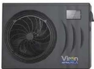
Exterior view of a black air conditioner unit with visible fan and ventilation grille (no text or symbols)
natural_image
Exterior view of a dual-panel air conditioner unit with fan blades and ventilation ducts (no text or symbols visible)VIRON RANGE INVERTER HEAT PUMPS
Installation & Instruction manual
FLUIDRA

For full warranty terms and conditions and to register your warranty, simply visit www.astralpool.com.au/warranty and complete your details. Or scan the QR code and be taken directly to the registration page.
Record your equipment details here for quick reference:
Model No.: ____
Serial No.:
CONTENTS
- Preface 1
- Specifications 4
2.1 Performance Data of Swimming Pool Heat Pump Unit 4
2.2 Dimensions for Swimming Pool Heat Pump Unit 7
- Installation and Connection 9
3.1 Installation illustration .....9
3.2 Swimming Pool Heat Pumps Location 10
3.3 How Close to Your Pool? 10
3.4 Swimming Pool Heat Pumps Plumbing 11
3.5 Swimming Pool Heat Pumps Electrical Wiring 12
3.6 Initial Start-up of the Unit 12
- Operation and Use 13
4.1 Color screen wire controller interface introduction 13
4.2 Color screen wire controller function introduction 14
4.3 Parameter list and breakdown table 21
4.4 Interface drawin 23
-
Maintenance and Inspection 28
-
Appendix 33
6.1 Cable specification 33
6.2 Comparison table of refrigerant saturation temperature 34
1. PREFACE
In order to provide our customers with quality, reliability and versatility, this product has been made to strict production standards. This manual includes all the necessary information about installation, debugging, discharging and maintenance. Please read this manual carefully before you open or maintain the unit. The manufacture of this product will not be held responsible if someone is injured or the unit is damaged, as a result of improper installation, debugging, or unnecessary maintenance. It is vital that the instructions within this manual are adhered to at all times. The unit must be installed by qualified personnel.
The unit can only be repaired by qualified installer centre, personnel or an authorised dealer.
Maintenance and operation must be carried out according to the recommended time and frequency, as stated in this manual.
- Use genuine standard spare parts only.
Failure to comply with these recommendations will invalidate the warranty.
- Swimming Pool Heat Pump Unit heats the swimming pool water and keeps the temperature constant. For split type unit, The indoor unit can be Discretely hidden or semi-hidden to suit a luxury house.
Our heat pump has following characteristics:
1 Durable
The heat exchanger is made of PVC & Titanium tube which can withstand prolonged exposure to swimming pool water.
2 Installation flexibility
The unit can be installed outdoors.
3 Quiet operation
The unit comprises an efficient rotary/ scroll compressor and a low-noise fan motor, which guarantees its quiet operation.
4 Advanced controlling
The unit includes micro-computer controlling, allowing all operation parameters to be set. Operation status can be displayed on the LCD wire controller. Remote controller can be chosen as future option.
WARNING
Do not use means to accelerate the defrosting process or to clean, Other than those recommended by the manufacturer.
The appliance shall be stored in a room without continuously operating ignition sources (for example: open flames, an operating gas appliance or an operating electric heater.)
Do not pierce or burn.
Be aware that refrigerants may not contain an odour,

Appliance shall be installed, operated and stored in a room with a floor area larger than X m ^2 . NOTE The manufacturer may provide other suitable examples or may provide additional information about the refrigerant odour.
1. PREFACE
This appliance can be used by children aged from 8 years and above and persons with reduced physical, sensory or mental capabilities or lack of experience and knowledge if they have been given supervision or instruction concerning use of the appliance in a safe way and understand the hazards involved. Children shall not play with the appliance. Cleaning and user maintenance shall not be made by children without supervision.
If the supply cord is damaged, it must be replaced by the manufacturer, its service agent or similarly qualified persons in order to avoid a hazard.
The appliance shall be installed in accordance with national wiring regulations.
Do not operate your air conditioner in a wet room such as a bathroom or laundry room.
Before obtaining access to terminals, all supply circuits must be disconnected.
An all-pole disconnection device which has at least 3mm clearances in all pole s, and have a leakage current that may exceed 10mA residual current device (RCD) having a rated residual operating current not exceeding 30mA, and disconnection must be incorporated in the fixed wiring in accordance with the wiring rules
Do not use means to accelerate the defrosting process or to clean, other than those recommended by the manufacturer
The appliance shall be stored in a room without continuously operating ignition sources (for example: open flames, an operating gas appliance or an operating electric heater.)
Do not pierce or burn
- Appliance shall be installed, operated and stored in a room with a floor area larger than X m2
Be aware that refrigerants may not contain an odour.
The installation of pipe-work shall be kept to a minimum X m2
Spaces where refrigerant pipes shall be compliance with national gas regulations.
Servicing shall be performed only as recommended by the manufacturer.
The appliance shall be stored in a well-ventilated area where the room size corresponds to the room area as specified for operation.
All working procedure that affets safety means shall only be carried by competent persons.
- Transport of equipment containing flammable refrigerants
Compliance with the transport regulations
Marking of equipment using signs
Compliance with local regulations
Disposal of equipment using flammable refrigerants
Compliance with national regulations
Storage of equipment/appliances
The storage of equipment should be in accordance with the manufacturer's instructions. Storage of packed (unsold) equipment
Storage package protection should be constructed such that mechanical damage to the equipment inside the package will not cause a leak of the refrigerant charge.
The maximum number of pieces of equipment permitted to be stored together will be determined by local regulations.
1. PREFACE
Caution & Warning
- The unit can only be repaired by qualified installer centre personnel or an authorised dealer. for Europe market
- This appliance is not intended for use by persons (including children) with reduced physical sensory or mental capabilities, or lack of experience and knowledge, unless they have been given supervision or instruction concerning use of the appliance by a person responsible for their safety. for Europe market Children should be supervised to ensure that they do not play with the appliance.
- Please make sure that the unit and power connection have good earthing, otherwise may cause electrical shock.
- If the supply cord is damaged, it must be replaced by the manufacturer or our service agent or similarly qualified person in order to avoid a hazard.
- Directive 2002/96/EC (WEEE): The symbol depicting a crossed-out waste bin that is underneath the appliance indicates that this product, at the end of its useful life, must be handled separately from domestic waste, must be taken to a recycling centre for electric and electronic devices or handed back to the dealer when purchasing an equivalent appliance.
- Directive 2002/95/EC (RoHs): This product is compliant with directive 2002/95/EC (RoHs) concerning restrictions for the use of harmful substances in electric and electronic devices.
- The unit CANNOT be installed near the flammable gas. Once there is any leakage of the gas, fire can be occur.
- Make sure that there is circuit breaker for the unit, lack of circuit breaker can lead to electrical shock or fire.
- The heat pump located inside the unit is equipped with an over-load protection system. It does not allow for the unit to start for at least 3 minutes from a previous stoppage.
- The unit can only be repaired by the qualified personnel of an installer center or an authorized dealer, for North America market
- Installation must be performed in accordance with the NEC/CEC by authorized person only. (for North America market)
- USE SUPPLY WIRES SUITABLE FOR 75 ℃
- Caution: Single wall heat exchanger, not suitable for potable water connection.
2.1 Performance data of Swimming Pool Heat Pump Unit
*** REFRIGERANT : R32
| UNIT | 78572 | 78573 | |
| Heating capacity(27/24.3 °C) | kW | 2.15~9 | 2.85~12 |
| Btu/h | 7310~30600 | 9690~40800 | |
| Heating Power Input | kW | 0.16~1.6 | 0.21~2.12 |
| COP | 13.44~5.63 | 13.57~5.66 | |
| Heating capacity(15/12 °C) | kW | 1.75~7.4 | 2.25~9.7 |
| Btu/h | 5950~25160 | 7650~32980 | |
| Heating Power Input | kW | 0.25~1.6 | 0.32~2.08 |
| COP | 7~4.63 | 7.03~4.66 | |
| Heating capacity(10/6.8 °C) | kW | 1.42~6.1 | 1.88~8 |
| Btu/h | 4828~20740 | 6392~27200 | |
| Heating Power Input | kW | 0.25~1.5 | 0.33~1.95 |
| COP | 5.68~4.07 | 5.7~4.1 | |
| Power Supply | 220-240V-/50Hz | 220-240V-/50Hz | |
| Compressor Quantity | 1 | 1 | |
| Compressor | rotary | rotary | |
| Fan Number | 1 | 1 | |
| Noise(1m) | dB(A) | 40-50 | 42-52 |
| Water Connection | mm | 48.3 | 48.3 |
| Water Flow Volume | m^2/h | 3.2 | 4.2 |
| Water Pressure Drop(max) | kPa | 4 | 4.5 |
| Unit Net Dimensions(L/W/H) | mm | See the drawing of the units | |
| Unit Ship Dimensions(L/W/H) | mm | See package lable | |
| Net Weight | kg | see nameplate | |
| Shipping Weight | kg | see package label | |
Heating: Outdoor air temp: 27/24.3, Inlet water temp:26
Outdoor air temp: 15/12, Inlet water temp:26 Outdoor
air temp: 10 /6.8, Inlet water temp:26
Operating range:
Ambient temperature:-15 43—℃
Water temperature:9-40 ℃
2.1 Performance data of Swimming Pool Heat Pump Unit
*** REFRIGERANT : R32
| UNIT | 78574 | 78575 | |
| Heating capacity(27/24.3 °C) | kW | 3.77~17 | 4.6~19.5 |
| Btu/h | 12818~57800 | 15640~66300 | |
| Heating Power Input | kW | 0.3~3.02 | 0.37~3.94 |
| COP | 12.57~5.63 | 12.43~4.95 | |
| Heating capacity(15/12 °C) | kW | 2.92~12.4 | 3.84~15.4 |
| Btu/h | 9928~42160 | 13056~52360 | |
| Heating Power Input | kW | 0.44~2.86 | 0.6~3.81 |
| COP | 6.64~4.34 | 6.4~4.04 | |
| Heating capacity(10/6.8 °C) | kW | 2.5~10.7 | 3.38~14.4 |
| Btu/h | 8500~36380 | 11492~48960 | |
| Heating Power Input | kW | 0.45~2.64 | 0.62~3.62 |
| COP | 5.56~4.05 | 5.45~3.98 | |
| Power Supply | 220-240V-/50Hz | 220-240V-/50Hz | |
| Compressor Quantity | 1 | 1 | |
| Compressor | rotary | rotary | |
| Fan Number | 1 | 1 | |
| Noise | dB(A) | 44-53 | 45-56 |
| Water Connection | mm | 48.3 | 48.3 |
| Water Flow Volume | m^2/h | 5.3 | 6.6 |
| Water Pressure Drop(max) | kPa | 5 | 6 |
| Unit Net Dimensions(L/W/H) | mm | See the drawing of the units | |
| Unit Ship Dimensions(L/W/H) | mm | See package lable | |
| Net Weight | kg | see nameplate | |
| Shipping Weight | kg | see package label | |
Heating: Outdoor air temp: 27/24.3, Inlet water temp: 26
Outdoor air temp: 15/12, Inlet water temp:26 Outdoor
air temp: 10 /6.8, Inlet water temp:26
Operating range:
Ambient temperature:-15 43—℃
Water temperature:9-40 ℃
2.1 Performance data of Swimming Pool Heat Pump Unit
*** REFRIGERANT : R32
| UNIT | 78576 | 78577 | |
| Heating capacity(27/24.3 °C) | kW | 5.7~24.2 | 6.7~28.3 |
| Btu/h | 19380~82280 | 22780~96220 | |
| Heating Power Input | kW | 0.46~4.8 | 0.54~5.57 |
| COP | 12.39~5.04 | 12.41~5.08 | |
| Heating capacity(15/12 °C) | kW | 4.68~19.9 | 5.46~23.3 |
| Btu/h | 15912~67660 | 18564~79220 | |
| Heating Power Input | kW | 0.72~4.74 | 0.83~5.49 |
| COP | 6.5~4.2 | 6.58~4.24 | |
| Heating capacity(10/6.8 °C) | kW | 4.2~17.8 | 4.9~20.8 |
| Btu/h | 14280~60520 | 16660~70720 | |
| Heating Power Input | kW | 0.75~4.4 | 0.87~5.1 |
| COP | 5.6~4.05 | 5.63~4.08 | |
| Power Supply | 220-240V~50Hz | 380-415V/3N~50Hz | |
| Compressor Quantity | 1 | 1 | |
| Compressor | rotary | rotary | |
| Fan Number | 2 | 2 | |
| Noise | dB(A) | 46-57 | 48-58 |
| Water Connection | mm | 48.3 | 48.3 |
| Water Flow Volume | m^2/h | 8.6 | 10 |
| Water Pressure Drop(max) | kPa | 11 | 15 |
| Unit Net Dimensions(L/W/H) | mm | See the drawing of the units | |
| Unit Ship Dimensions(L/W/H) | mm | See package lable | |
| Net Weight | kg | see nameplate | |
| Shipping Weight | kg | see package label | |
Heating: Outdoor air temp: 27/24.3, Inlet water temp:26
Outdoor air temp: 15/12, Inlet water temp:26 Outdoor
air temp: 10 /6.8, Inlet water temp:26
℃
Operating range:
Ambient temperature:-15 43— ℃
Water temperature:9-40 ℃
℃
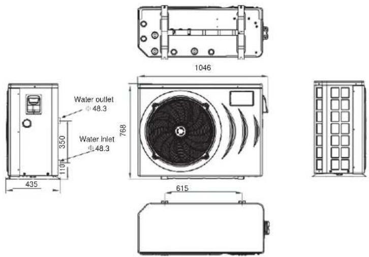
2.2 The dimensions for Swimming Pool Heat Pump Unit
UNIT: 78572/78573
unit mm
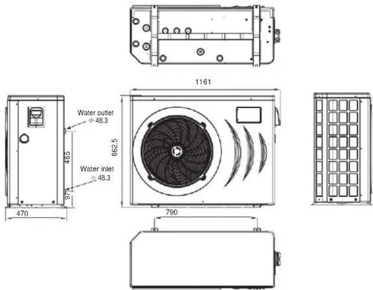
UNIT: 78574/78575
unit mm
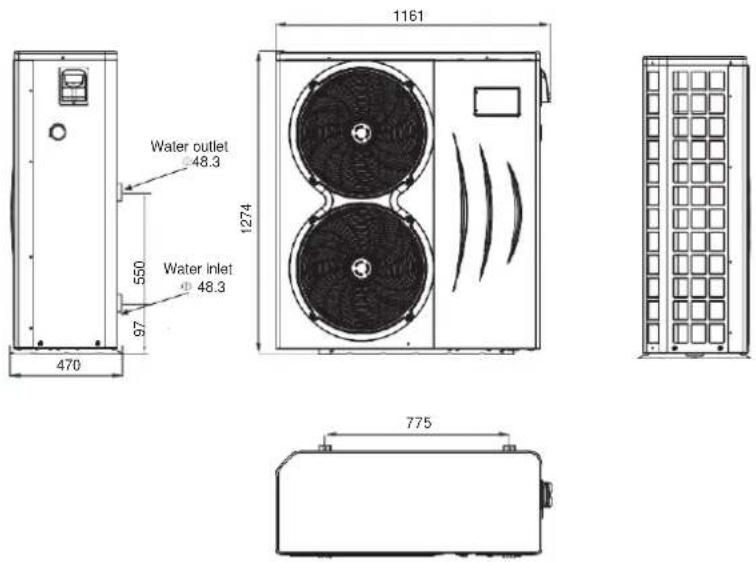
2.2 The dimensions for Swimming Pool Heat Pump Unit
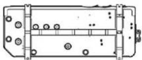
UNIT: 78576/78577
unit mm
3. INSTALLATION AND CONNECTION
3.1 Installation illustration
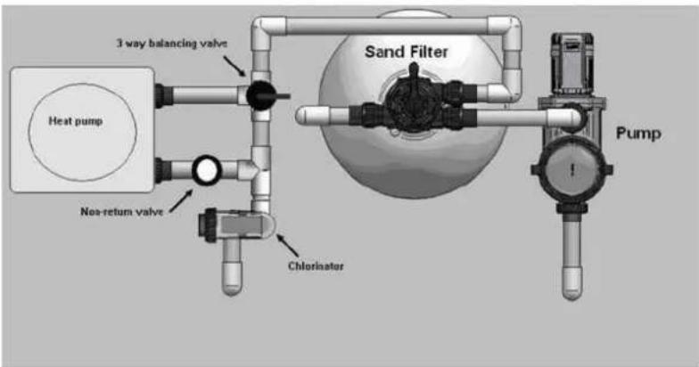
Installation items:
The factory only provides the main unit and the water unit; the other items in the illustration are necessary spare parts for the water system, that provided by users or the installer.
Attention:
Please follow these steps when using for the first time
-
Open valve and charge water.
-
Make sure that the pump and the water-in pipe have been filled with water.
-
Close the valve and start the unit.
ATTN: It is necessary that the water-in pipe is higher than the pool surface.
The schematic diagram is for reference only. Please check the water inlet/outlet label on the heat pump while plumbing installation.
The schematic diagram is for reference only. Please check the water inlet/outlet label on the heat pump while plumbing installation.
The controller is mounted on the wall
IMPORTANT NOTE:
A WATER BY-PASS MUST BE PLUMBED TO REGULATE WATER FLOW TO HEAT PUMP. FAILURE TO DO SO MAY RESULT IN POOR EFFICIENCY A ND REDUCED HEATING OUTPUT.
3. INSTALLATION AND CONNECTION
3.2 Swimming Pool Heat Pumps Location
The unit will perform well in any outdoor location provided that the following three factors are presented:
1. Fresh Air - 2. Electricity - 3. Pool filter piping
The unit may be installed virtually anywhere outdoors. For indoor pools please consult the supplier. Unlike a gas heater, it has no draft or pilot light problem in a windy area.
DO NOT place the unit in an enclosed area with a limited air volume, where the units discharge air will be re-circulated.
DO NOT place the unit to shrubs which can block air inlet. These locations deny the unit of a continuous source of fresh air which reduces it efficiency and may prevent adequate heat delivery.

3.3 How Close To Your Pool?
Normally, the pool heat pump is installed within 7.5 metres of the pool. The longer the distance from the pool, the greater the heat loss from the piping. For the most part, the piping is buried. Therefore, the heat loss is minimal for runs of up to 15 meters (15 meters to and from the pump = 30 meters total), unless the ground is wet or the water table is high. A very rough estimate of heat loss per 30 meters is 0.6 kW-hour, (2000BTU) for every 5 °C difference in temperature between the pool water and the ground surrounding the pipe, which translates to about 3% to 5% increase in run time.
3. INSTALLATION AND CONNECTION
3.4 Swimming Pool Heat Pumps Plumbing
The Swimming Pool Heat Pumps exclusive rated flow titanium heat exchanger requires no special plumbing arrangements except bypass(please set the flow rate according to the nameplate). The water pressure drop is less than 10kPa at max. Flow rate. Since there is no residual heat or flame Temperatures, The unit does not need copper heat sink piping. PVC pipe can be run straight into the unit.
Location: Connect the unit in the pool pump discharge (return) line downstream of all filter and pool pumps, and upstream of any chlorinators, ozonators or chemical pumps.
Standard model have slip glue fittings which accept 32mm or 50 mm PVC pipe for connection to the pool or spa filtration piping. By using a 50 NB to 40NB you can plumb 40NB
Give serious consideration to adding a quick coupler fitting at the unit inlet and outlet to allow easy draining of unit for winterizing and to provide easier access should servicing be required.

Condensation: Since the Heat pump cools down the air about 4-5 °C, water may condense on the fins of the horseshoe shaped evaporator. If the relative humidity is very high, this could be as much as several litres an hour. The water will run down the fins into the basepan and drain out through the barbed plastic condensation drain fitting on the side of the basepan. This fitting is designed to accept 20mm clear vinyl tubing which can be pushed on by hand and run to a suitable drain. It is easy to mistake the condensation for a water leak inside the unit.
NB: A quick way to verify that the water is condensation is to shut off the unit and keep the pool pump running. If the water stops running out of the basepan, it is condensation. AN EVEN QUICKER WAY IS to TEST THE DRAIN WATER FOR CHLORINE - if the is no chlorine present, then it's condensation.
IMPORTANT N OTE:
A WA TER BY-PASS MUST BE PLUMBED TO REGULATE WA TER F LOW TO HEAT PUMP. FAILURE TO D O SO MAY RESULT IN POOR EFFICIENCY AND REDUCED HEATING OUTPUT.
3. INSTALLATION AND CONNECTION
3.5 Swimming Pool Heat Pumps Electrical Wiring
NOTE: Although the unit heat exchanger is electrically isolated from the rest of the unit, it simply prevents the flow of electricity to or from the pool water. Grounding the unit is still required to protect you against short circuits inside the unit. Bonding is also required.
The unit has a separate molded-in junction box with a standard electrical conduit nipple already in place. Just remove the screws and the front panel, feed your supply lines in through the conduit nipple and wire-nut the electric supply wires to the three connections already in the junction box (four connections if three phase). To complete electrical hookup, connect Heat Pump by electrical conduit, UF cable or other suitable means as specified (as permitted by local electrical authorities) to a dedicated AC power supply branch circuit equipped with the proper circuit breaker, disconnect or time delay fuse protection.
Disconnect - A disconnect means (circuit breaker, fused or un-fused switch) should be located within sight of and readily accessible from the unit. This is common practice on commercial and residential air conditioners and heat pumps. It prevents remotely-energizing unattended equipment and permits turning off power at the unit while the unit is being serviced.
3.6 Initial startup of the Unit
NOTE- In order for the unit to heat the pool or spa, the filter pump must be running to circulate water through the heat exchanger.
Start up Procedure - After installation is completed, you should follow these steps:
- Turn on your filter pump. Check for water leaks and verify flow to and from the pool.
- Turn on the electrical power supply to the unit, then press the key ON/OFF of wire controller, It should start in several seconds.
- After running a few minutes make sure the air leaving the top(side) of the unit is cooler(Between 5-10 ) °C
- With the unit operating turn the filter pump off. The unit should also turn off automatically,
- Allow the unit and pool pump to run 24 hours per day until desired pool water temperature is reached. When the water-in temperature reaches this setting, the unit will slow down for a period of time, if the temperature is maintained for 45 minutes the unit will turn off. The unit will now automatically restart (as long as your pool pump is running) when the pool temperature drops more than 0.2 below set temperature.
Time Delay- The unit is equipped with a 3 minute built-in solid state restart delay included to protect control circuit components and to eliminate restart cycling and contactor chatter.
This time delay will automatically restart the unit approximately 3 minutes after each control circuit interruption. Even a brief power interruption will activate the solid state 3 minute restart delay and prevent the unit from starting until the 5 minute countdown is completed.
4. Operationanduse
4.1
Color screen wire controller interface introduction
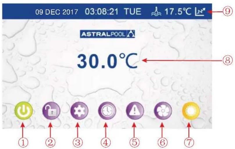
4.1.1 Maininterface
4.1.2 Button Description
| NO. | Name | The button function |
| 1 | ON/OFF | Press to start /shut off the unit |
| 2 | LOCK | Click to lock the screen, Input "22" to unlock the screen by press the "lock button" |
| 3 | Parameter | Click this button to view the unit state and the parameter |
| 4 | CLOCK | Press to set the clock, the timer on or timer off |
| 5 | Fault display | Click to view fault history |
| 6 | Silent setting | Click to turn on/off silent function and to set timing Low speed function. |
| 7 | MODE | Click to enter the mode switch interface |
| 8 | Water Inlet Temp. | Click to enter mode setting and the target temp. Setting interface |
| 9 | Temp. curve | Click to view the temp. and power curve |
4.2 Color screen wire controller function introduction
4.2.1 Booting and shutdown
As shown in figure 1.1:
In shutdown status, click ① then the unit will be booted
In booting status, click ① then the unit will be shut down.
4.2.2 Mode switch and target temperature Setting
2.2 1 Mode switch
In the main interface, click mode button or inlet water temperature setting button, interface displays as follows:
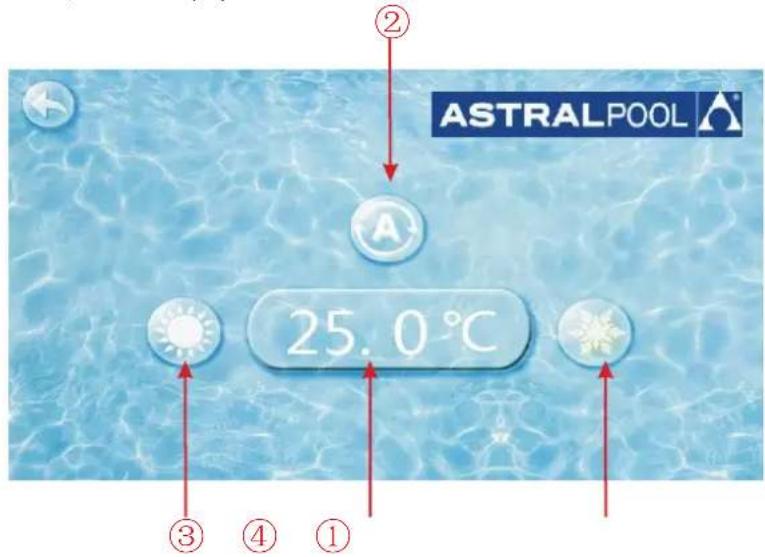
Click the refrigeration mode button ①, automatic mode button ② or heating mode button ③ then you can select the corresponding mode.
Note: when the unit is designed for single automatic mode or single thermal mode, the mode can not be switched.
2.2.2 Target temp. setting
Clice the temperature set button ④, you can set the target temperature.
4.2.3 Clock setting
In the main interface, click on the clock Settings button, interface displays as follows:
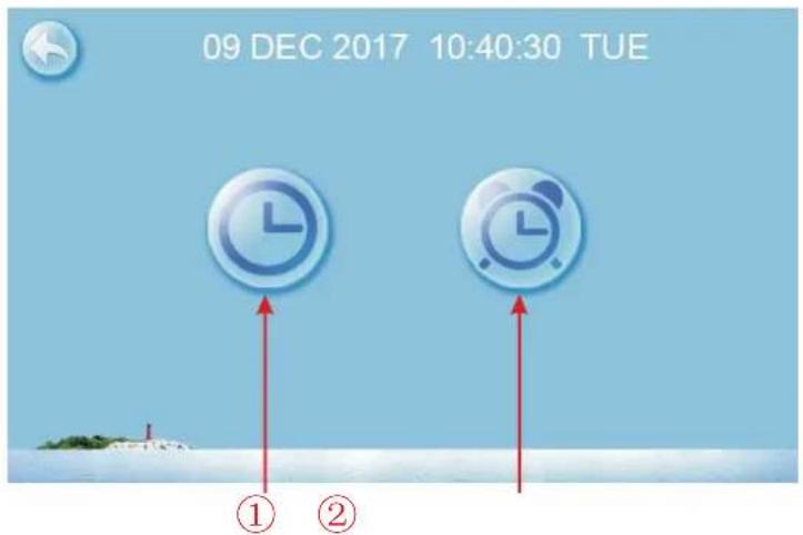
2.3.1 The operation of time setting
Click on the time Settings button ① , interface displays as follows:
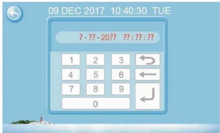
Click the value to set time directly, the click confirm button to save the Settings.
For example: setup time: the 30-11-2016 16:00:00, input 30 11 16 16 00 00, the time change then click confirm button.
Note: if the input format is not correct, the wrong time will be saved by clicking confirm button.
4. Operation and use
2.3.2 The operation of timing setting
Click the timing set button ② to enter timing setinterface.
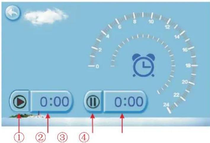
| NO. | Name | Button color | Button function |
| 1 | Timing start button | Start: greenEnd: gray | Click this button to start or end timing start setting function |
| 2 | Timing on setting | Click to set start time of the timing | |
| 3 | Timing end button | Open: redEnd: gray | Click this button to start or end timing end setting function |
| 4 | Timing off setting | Click to set end time of the timing |
For example above: without action, 0 o 'clock and 1o 'clock will be the on and off time of timing settings.
4.2.4 Silent setting and silent timing setting
Click the silent setting button, and the interface displays as follows:

2.4.1 The silent button
Click the silent button ①, the unit will enter the silent mode, and interface displays as follows:

Click the silent button ① again, to exit the silent mode.
4. Operation and use
2.4.2 Timing silent function setting
Click timing silent button ②, and interface displays as follows:
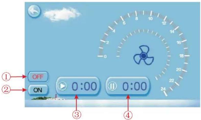
| NO. | Name | Color | Function |
| 1 | Timing silent off | Used: red Unused:gray | Click to use or unuse timing off function |
| 2 | Timing silent on | Use:green Unused:gray | Click to use or unuse timing on function |
| 3 | Timing silent start time | Click this button to set the timing silent start time | |
| 4 | Timing silent end time | Click this button to set the timing silent end time |
Start time and end time setting value must be among the range of 0:00-23:00, and setting value can be precise to hour digit.
For example above, click "ON" to use timing silent, the unit will start the silent at 0:00 points and end at 4:00; click "OFF" to unuse the timing silent, but if the unit is in timing silent mode, it will exit silent timing immediately.
4.2.5 History of the fault
In the main interface click fault display key, interface displays as follows:

If no failure, main interface displays static " "
When fault occurs, the fault icon will flash between the " " " .! the failure interface will record time, code, name of the fault.
After troubleshooting, if you do not check the failure record, the main interface will display static "⚠"; if you check the failurerecord, the main interface will displays static "⚠";
Failure record is in reverse order, according to the happening time.
Press the "Clean" key, you can delete the fault record.
4.2.6 Color Display Calibration
Keep click quickly at the blank area on any interface till you hear a long beep. Then you will enter the calibration interface. Click "+" to start calibration. When you hear the beep again, you will finish calibration and exit.
Remark: the wire controller can display the temperature unit as "T" or "C" according to the unit model you bought.
4.2.7 Temperature curve
In the main interface, click the curve display button, interface displays as follows:
2.7.1 Temperature recording curve is as follows:

line
| Time | Inlet water (°C) | Outlet water (°C) | |---|---|---| | 0h | 25 | 20 | | 6h | 24 | 19 | | 12h | 25 | 18 | | 18h | 26 | 21 | | 24h | 23 | 19 |2.7.2 Comp.Frequency curve

line
| Time | Temperature | | ---- | ----------- | | 0h | ~30Hz | | 6h | ~50Hz | | 12h | ~60Hz | | 18h | ~50Hz | | 24h | ~30Hz |Temperature curve automatically updates every one hour, and the curve record can be stored for 60 days;
Start from the latest curve saved time, if power is off and curve data collecting time is less than one hour, the data in this period will not be saved;
4.3 Parameter list and breakdown table
(1) Electronic control fault table
Can be judged according to the remote controller failure code and troubleshooting
| Protect/fault | Fault display | Reason | Elimination methods |
| Standby | Non | ||
| Normal boot | Non | ||
| Inlet Temp. Sensor Fault | P01 | The temp. Sensor is broken or short circuit | Check or change the temp. Sensor |
| Outlet Temp. Sensor Fault | P02 | The temp. Sensor is broken or short circuit | Check or change the temp. Sensor |
| Ambient Temp. Sensor Fault | P04 | The temp. Sensor is broken or short circuit | Check or change the temp. Sensor |
| Coil Temp. Sensor Fault | P05 | The temp. Sensor is broken or short circuit | Check or change the temp. Sensor |
| Suction Temp. Sensor Fault | P07 | The temp. Sensor is broken or short circuit | Check or change the temp. Sensor |
| Discharge Temp. Sensor Fault | P081 | The temp. Sensor is broken or short circuit | Check or change the temp. Sensor |
| High Pressure Prot. | E01 | The high-pressure switch is broken | Check the pressure switch and cold circuit |
| Low Pressure Prot. | E02 | Low pressure1 protection | Check the pressure switch and cold circuit |
| Flow Switch Prot. | E03 | No water/little water in water system | Check the pipe water flow and water pump |
| Anti-freezing Prot | E07 | Water flow is not enough | Checkth ep ipew aterfl owa ndw hether waters ystemi sja mmedo m ot |
| Primary Anti-freezing Prot. | E19 | The ambient temp. Is low | |
| Secondary Anti-freezing Prot. | E29 | The ambient temp. Is low | |
| Inlet and outlet temp. too big | E06 | Water flow is not enough and low differential pressure | Check the pipe water flow and whether water system is jammed or not |
| Low temperature protection | Non | The environment temp. is low | |
| Comp. Overcurrent Prot. | E051 | The compressor is overload | Check whether the system of the compressor running normally |
| Exhaust Air over Temp Prot. | P082 | The compressor is overload | Check whether the system of the compressor running normally |
| Communication Fault | E08 | Communicat ion failure between wire controller and mainboard | Check the wire connection between remote wire controller and main board |
| Antifreeze Temp. Sensor Fault | P09 | antifreeze temp sensor is broken or short circuited | check and replace this temp sensor |
| Waterway Anti-freezing Prot. | E05 | water temp.or ambient temp. is too low | |
| EC fan feedback Fault | F051 | There is something wrong with fan motor and fan motor stops running | Check whether fan motor is broken or locked or not |
| Pressure sensor Fault | PP | The pressure Sensor is broken | Check or change the pressure Sensor or pressure |
| Fan Motor1 Fault | F031 | 1. Motor is in locked-rotor state2. The wire connection between DC-fan motor module and fan motor is in bad contact | 1. Change a new fan motor2. Check the wire connection and make sure they are in good contact |
4. OPERATION AND USE
| Fan Motor2 Fault | F032 | 1. Motor is in locked-rotor state2. The wire connection between DC-fan motor module and fan motor is in bad contact | 1. Change a new fan motor2. Check the wire connection and make sure they are in good contact |
| Communication Fault (speed control module) | E081 | Speed control module and main board communication fail | Checkthe communication connection |
Frequency conversion board fault table:
| Protection/fault | Fault display | Reason | Elimination methods |
| Drv1 MOP alarm | F01 | MOP drive alarm | Recoveryafter the 150s |
| Inverter offline | F02 | Frequency conversion board and main board communication failure | Checkthe communicationconnection |
| IPM protection | F03 | IPM modular protection | Recoveryafter the 150s |
| Comp. Driver Failure | F04 | Lack of phase, step or drive hardware damag | Checkthe measuringvoltage check requencyconversion board hardware |
| DC Fan Fault | F05 | Motor current feedback open circuit or short circuit | Checkwhether currentreturn wires connectedmotor |
| IPM Overcurrent | F06 | IPM Input current is large | Checkand adjustthe current measurement |
| Inv. DC Overvoltage | F07 | DC bus voltage>Dc bus over-voltage protection value | Checkthe input voltagemeasurement |
| Inv. DC Lessvoltage | F08 | DC bus voltage<DC bus over-voltage protection value | Checkthe input voltagemeasurement |
| Inv. Input Lossvolt. | F09 | The input voltage is low, causing the inputcurrent is high | Checkthe input voltagemeasurement |
| Inv. Input Overvolt. | F10 | The input voltage is too high, more than outage protection current RMS | Checkthe input voltagemeasurement |
| Inv. Sampling Volt. | F11 | The input voltage sampling fault | Checkand adjustthe current measurement |
| Comm. Err DSP-PFC | F12 | DSP and PFC connect fault | Checkthe communicationconnection |
| Input Over Cur. | F26 | The equipment load is too large | |
| PFC fault | F27 | The PFC circuit protection | Check the PFC switch tube short circuit or not |
| IPM Over heating | F15 | The IPM module is overheat | Checkand adjustthe current measurement |
| Weak Magnetic Warn | F16 | Compressor magnetic force is not enough | |
| Inv. Input Out Phase | F17 | The input voltage lost phase | Checkand measurethe voltage adjustment |
| IPM Sampling Cur. | F18 | IPM sampling electricity is fault | Checkand adjustthe current measurement |
| Inv. Temp. Probe Fail | F19 | Sensor is short circuit or open circuit | Inspectand replacethe sensor |
| Inverter Overheating | F20 | The transducer is overheat | Checkand adjustthe current measurement |
| Inv. Overheating Warn | F22 | Transducer temperature is too high | Checkand adjustthe current measurement |
| Comp. OverCur. Warn | F23 | Compressor electricity is large | The compressorover-current protection |
| Input Over Cur. Warn | F24 | Input current is too large | Checkand adjustthe current measurement |
| EEPROM Error Warn | F25 | MCU error | Checkwhether the chip is damagedReplacethe chip |
| V15V over/undervoltage fault | F28 | The V15V is overload or undervoltage | Check the V15V input voltage in range 13.5v~16.5v or not |
(2) Parameter list
| Meaning | Default | Remarks |
| Refrigeration target temperature set point | 27°C | Adjustable |
| Heating the target temperature set point | 27°C | Adjustable |
| Automatic target temperature set point | 27°C | Adjustable |
4.4 Interface drawin
(1) Wire control interface diagram and definition
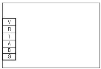
| Sign | Meaning |
| V | 12V power + |
| R | No use |
| T | No use |
| A | 485A |
| B | 485B |
| G | GND(power-) |
(2) Controller interface diagram and definition
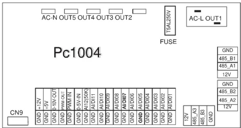
Main board of the input and output interface instructions below
| Number | Sign | Meaning | ||
| 01 | OUT1 | Compressor ( output 220-230VAC | ||
| 02 | OUT2 | Water pump ( output 220-230VAC | ||
| 03 | OUT3 | 4-way valve ( output 220-230VAC | ||
| 04 | OUT4 | High speed of fan ( output 220-230VAC | ||
| 05 | OUT5 | Low speed of fan (output 220-230VAC | ||
| 06 | AC-L | Live wire ( input 220-230VAC | ||
| 07 | AC-N | Neutral wire ( input 220-230VAC | ||
| 08 | AI/DI01 | Emergency switch input | ||
| 09 | AI/DI02 | Water flow switch input | ||
| 10 | AI/DI03 | System low pressure input | ||
| 11 | AI/DI04 | System high pressure input | ||
| 12 | AI/DI05 | System suction temperature input | ||
| 13 | AI/DI06 | Water input temperature input | ||
| 14 | AI/DI07 | Water output temperature ( input ) | ||
| 15 | AI/DI08 | System fan coil temperature input | ||
| 16 | AI/DI09 | Ambient temperature input | ||
| 17 | AI/DI10 | Mode switch input | ||
| 18 | AI/DI11 | Master-slave machine switch / Antifreeze temperature input | ||
| 19 | AI12(50K) | System Exhaust temperature input | ||
| 20 | 0_5V_IN | Compressor current detection/Pressure sensor(input) | ||
| 21 | PWM_IN | Master-slave machine switch / Feedback signal of EC fan ( input ) | ||
| 22 | PWM_OUT | AC fan control ( output ) | ||
| 23 | 0_10V_OUT | EC fan control ( output ) | ||
| 24 | +5V | +5V ( output ) | ||
| 25 | +12V | +12V ( output ) | ||
| 26 | GND | Frequency conversion board communications | ||
| 27 | 485_B1 | |||
| 28 | 485_A1 | |||
| 29 | 12V | |||
| 30 | GND | Color line controller communication | ||
| 31 | 485_B2 | |||
| 32 | 485_A2 | |||
| 33 | 12V | |||
| 34 | CN9 | Electronic expansion valve | ||
| 35 | GND | The port for centralized control system | ||
| 36 | 485_B3 | |||
| 37 | 485_A3 | |||
| 38 | 12V | |||
Controller interface diagram and definition

Controller interface diagram and definition

Main board of the input and output interface instructions below
| Number | Sign | Meaning |
| 01 | P10-(U) | Compressor ( output 220-230VAC ) |
| 02 | P10-(V) | |
| 03 | P10-(W) | |
| 04 | CN18(EMV) | Water pump ( output 220-230VAC ) |
| 05 | CN13(HEAT) | 4-way valve ( output 220-230VAC ) |
| 06 | CN96(H) | High speed of fan ( output 220-230VAC ) |
| 07 | CN96(L) | Low speed of fan (output 220-230VAC ) |
| 08 | P1(AC-L) | Live wire ( input 220-230VAC ) |
| 09 | P2(AC-N) | Neutral wire ( input 220-230VAC ) |
| 10 | CN99(PL) | Pressure sensor |
| 11 | CN29(OVT) | Water flow switch ( input ) |
| 12 | CN30(HP) | High pressure switch ( input ) |
| 13 | CN31(LP) | Low pressure switch ( input ) |
| 14 | CN7(OAT) | System suction temperature ( input ) |
| 15 | CN21(RES1) | Water input temperature ( input ) |
| 16 | CN22(RES2) | Water output temperature ( input ) |
| 17 | CN8(OPT) | System fan coil temperature ( input ) |
| 18 | CN12(PH) | Ambient temperature ( input ) |
| 19 | CN9(OHT) | System Exhaust temperature ( input ) |
| 20 | P00iGND) | Earth wire |
| 21 | P01iGND) | Earth wire |
| 22 | P13iL) P14iL) | Electric reactor |
| 23 | R483(B) R485(A) | Color line controller communication |
| 24 | CN15 | Electronic expansion valve |
5. MAINTENANCE AND INSPECTION
Check the water supply device and the release often. You should avoid the condition of no water or air entering into system, as this will influence unit's performance and reliability. You should clear the pool/spa filter regularly to avoid damage to the unit as a result of the dirty of c logged filter.
The area around the unit should be dry, c lean and well v entil ated. C lea n the side heating exc hanger regularly to maintain good heat exc hange as c ons erve ene rgy .
The operation press ure of the refrigerant sys tem should only be serviced by a certified technici an.
Check the power supply and cable connection often,. Should the uni t b egin to operate abnormally, s witch it off and c contact the qualified tec hni cian.
Dis charge all water in the water pump and water system, so that freezing of the water in the pump or water system does not occur. You should discharge the water at the bottom of water pump if the unit will not be used for an extended period of time. You should check the unit thoroughly and fully the system with water fully before using it for the first time after a prolonged period of no usage.
Check s to the area Prior to beginning work on sy stems containing fl am mabl e refrigerants, safety c checks are neces sary to ens ure that the risk of ignition is mini mised. For repai r to t he refrigerating sy stem, the foll owing pr ec auti ons shall be complied with prior to c ondu c ting work on the sy stem.
Work procedure Work s hal l be undertak en under a c ontrol led proc edur e s o as to minim i se the ris k of a flammable gas or v apour being present while the work i s being perform ed.
General w or k area All maintenance staff and others working in the local area shall be inscribed on the nature of w or k being carried out. Work in confined space shall be avoided. The area around the work space shall be secured off. Ensure that the conditions within the area have been made safe by control of flammable material.
- Check ing for presenc e of refri gerant The area s hall be c heck ed wi th an appropriate refri ger ant detect tor prior to and during work, to ens ur e the technic ian is aware of potential ly f lammable atmos phere s . Ensure that the leak detection equipment bei ng us ed is suitable for use with fl am mabl e refrigerants, i. e. non-spark ing, adequately s ealed or intrins icall y safe.
Presence of fire extinguish her If any hot w or k is to be conducted on the refri ger ation equipment or an y ass oc iated parts, appropriate fire extinguishing equipment shall be av ai lable to hand. Have a dry powder or CO 2 fir e ex tinguis her adjacent to the charging area.
5. MAINTENANCE AND INSPECTION
No ignition sources
No person carrying out work in relation to a refrigeration system which involves exposing any pipe work that contains or has contained flammable refrigerant shall use any sources of ignition in such a manner that it may lead to the risk of fire or ex plosion. All possible ignition sources, including cigarette smoking, should be kept sufficiently far away from the site of insular lati on, repairing, removing and disposing, during which amable refrigerant can possibly be released to the surrounding space. Prior to work taking place, the area around the equipment is to be surveyed to make sure that there are no flammable hazards or ignition risk. No Smoking signs shall be displayed.
Ventilated area
Ensure that the area i s in the open or that it is adequately venti lated before e breaki ng into the sys tem or conducting any hot work . A deg ee of v entl lati on s hal I conti nue during the period that the work is carried out. The ventilation s hould s afel y dispers e any rel eas ed refrigerant and pr eferably ex pel it ex ternally into the atmosphere.
Check s to the refri ger ation equipment
Where electrical components are being c hanged, they s hall be f it for the purpose and to the corr ec t s pecific ation. At all times the manufac turer's m ai tenance and s ervi ce gui del ines shall be followed. I f i n doubt c consult the manufac turer's tec hni cal depart ment for ass istance.
The following checks shall be applied to ins tal lati ons using fl am mabl e refrigerants:
The charge si ze is in acc ordanc e with the room s ize wi thin whic h the refr igerant containing parts are i nstalled;
The ventilation machinery and outlets are operating adequately and are not obstructed;
If an indirect refrigerating circuit is being used, the secondary circuit shall be checked for the presence of refrigerant;
Marking to the equipment continues to be visible and legible. Markings and signs that are illegible shall be corrected;
Refrigeration pi pe or components are installed in a posi ti on where they are unlik ely to be expos ed to any s substance whic h may c orrode r refrigerant contai ni ng c omponents, unless the c omponents are construc ted of materials w hi ch are i nherently res istant to bei ng corr oded or are s uitabl y protec ted against bei ng s o c orroded.
Check s to el e c t rical devi ces
Repair and main tenance to electronic components shall include lude initial safety checks and component inspection procedures. If a fault exists that could compromise safety, then no electric al supply shall be connected to the circuit until it is at its fac for it dealt with. If the fault cannot be or rected immediately but it is necessary to continue operation, an adequate temporary solution shall be used. This shall be reported to the owner of the equipment so all parties are advised.
Initi al safety c hecks shall inc lude:
. That capacitors are discharged: this shall be done in a safe manner to avoid possibility of sparkling;
. That there no live elec tri cal components and wiring are ex pos ed w hile charging, recov ering or purging the system;
. That there is conti nui ty of earth bonding.
5. MAINTENANCE AND INSPECTION
Repairs to sealed components
1) During repairs to sealed components, all electrical supplies shall be disconnected from the equipment being worked upon prior to any removal of sealed covers, etc. If it is absolute necessary to have an electric supply to equi pm ent during service, then a permanently operating form of leak detection on shall be located at the most critical point to warn of a potentially hazardous situation.
2) Particular attention shall be paid to the following to ensure that by working on electrical components, the casing is not altered in such a way that the level of protection is affected. This shall include damage to cables, excessive number of connections, terminals not made to original specification, damage to seals, incorrect fitting of glands, etc.
- Ensure that apparatus is mounted securely.
Ensure that seals or sealing materials have not degraded such that they no longer serve the purpose of preventing the ingress of flammable atm os pheres. Repl acement parts shall be in ac cordance with the manufac tur er's speci fi cations. NOTE: The use of sili con sealant may inhibit the effectiveness of some types of leak detection on equipment. Intrinsic ally safe components do not have to be isolated prior to working on them.
Repair to i ntrins ical ly safe components
Do not apply any permanent inductive or capacitance loads to the circuit without ensuring that this will not exceed the permissible voltage and current permitted for the equipment in use.
Intrinsically safe components are the only types that can be worked on while live in the presence of a flammable atmosphere. The test apparatus shall be at the correct rating. Replace component s only with parts spec if ed by the manufacturer. Other parts may result in the ignition of refrigerant i n the atmosphere f rom a leak.
Cabling
Check that cabling will not be subject to wear, corrosion, excessive presure, vibration, sharp edges or any other advers environmental effect. The check shall also take into account the effects of aging or continual vibration from sources such as compressors or fans.
Detection of f lammable refri gerants
Under no c irc um stanc es shall potenti al sources of ignition be used in the searc hing for or detec ti on of refri gerant leaks. A halide torc h (or any other detector using a nak ed f lame) shall not be us ed.
Leak detect ti on methods
The following leak detection methods are deemed acceptable for systems containing flammable refrigerants.
Electronic leak detectors shall be used to detect flammable refrigerants, but the sensors may not be adequate, or may need re-cali bration. (Detect ion equipment shall be calibrated in a refrigerant-free area.) Ensure that the detector is not a potential source of ignition and is suitable for the refrigerant used. Leak detection equipment shall be set at a percentage of the LF L of the refrigerant and shall be calibrated to the refrigerant employed and the appropriate percentage of gas (25% maximum) is confirmed.
Leak detecti on f luids are sui table for us e w ith mos t refrigerants but the use of detergents containing chlorine shall be avoi ded as the c hlorine may react with the refri ger ant and corr ode the c opper pipe-work.
I f a leak is s uspected, all nak ed f flames s hall be removed/ extinguished.
If a leakage of refrigerant is found which requires brazing, all of the refrigerant shall be recovered from the system, or isolated (by means of shut off valves) in a part of the system remote from the leak. Oxy gen free nitrogen (OF N) shall then be purged through the system both before and during the brazing process.
5. MAINTENANCE AND INSPECTION
Removal and evacuation
When breaking into the refrigerant circ ui t to m ak e repai rs or for any other purpos e conv entional procedures s hall be us ed. However, it is important that bes t prac ti ce is followed sinc e f lammabil ity is a consi deration. T he following proc edure s hall I be adhered to:
. R emove refri ger ant;
. Purge the circuit with inert gas;
. Ev acuate;
. Purge again with inert gas;
. Open the cir cuit by cutti ng or brazi ng.
The refrigerant charge shall be recov ered i into the corr ec t rec overy c yli nders . T he s ystem shall be "f lus hed" wi th OFN to r ender the unit safe. This pr oc ess m ay need to be repeated sev eral ti mes. C ompressed air or oxy gen s hal I not be us ed for this tas k.
FI us hing shall be ac hieved by break ing the v acuum in the sy stem with OFN and continuing to fi ill until the w or king press ur e is achiev ed, then venting to atm os phere, and fi inall y pulling down to a vacuum. This proc ess s hal I be repeated until no r refrigerant is within the s system.
When the final OFN c harge is used, the sys tem s hall be v ented down to atmos pher ic press ure to enable work to take place. T his operati on is abs olutel y vi tal if brazing operati ons on the pipe-w ork are to tak e pl ace.
Ensure that the outl et for the vacuum pump is not c lose to any i gni tion sourc es and there is ventilation available. worki ng on them.
Labelling
Equipment shall be labelled stating that i t has been de-c ommissioned and emptied of refrigerant. The label s hall be dated and si gned. Ens ure that there are labels on the equipment s tating the equipment contains f lammable refr igerant .
Rec overy
When rem ov ing refri ger ant fr om a sy stem, ei ther for s ervi cing or dec ommis sioning, i t is recomm ended good practic e that al I refri gerants are removed saf ely.
When t transferring refrigerant into cy linders, ens ure that only appropri ate refr igerant recov ery cy linders are employed. Ens ure that the correc t number of cy linders for hol ding the total s ys tem c harge is av ailable. All c ylinders to be us ed are designated for the recov ered refrigerant and labelled for that refrigerant (i .e. special c yl ind er s for the r ec overy of refrigerant). Cy linders s hall be c omplete wi th press ure r el ief valve and as soci ated shut- off valv es in good work ing order. Empty rec overy c yli nders are ev acuated and, if possi ble, cooled before rec ov ery occ urs.
The recov ery equipment shall be in good w or king order w ith a set of ins truc ti ons conc erning the equipment that is at hand and s hal I be s suitable for the recov ery of f lammable refri ger ants. In addition, a set of c al ibrated weighing sc ales shall be avail able and i n good worki ng order. Hos es shall be complete with I eak -free dis connect couplings and i n good condition. Before e us ing the recovery machine, c heck that it is in s atis fac tor y working order, has been proper ly maintained and that any associated elec tri cal components are s ealed to prevent i gni ti on in the ev ent of a refr igerant release. Consult manufac turer if in doubt .
The recov ered refrigerant s hall be r eturned to the refrigerant s uppl ier in the correc t recov ery cy linder, and the relevant Was te Transfer Note arranged. Do not mi x refrigerants in recov ery units and es pec ially not in cy linders.
If c om pr es sors or c ompress or oil s are to be removed, ensure that they have been evacuated to an ac ceptable level to make c ertai n that f lammable refrigerant does not remain within the lubric ant. The ev acuation process shall be carried out prior to returning the compressor to the suppliers . Only elec tr ic heating to the compress or body shall be employed to ac celerate this process . When oil is drained from a sy stem, it shall be carried out safely.
5. MAINTENANCE AND INSPECTION
Dec om miss ioning
Before carrying out this procedure, it is essential that the technician is completely familiar with the equipment and all its detail. It is recommended good practice that all refrigerants are recovered safely. Prior to the tas k being carried out, an oil and refrigerant sample shall be taken in case analysis is required prior to re-use of reclaimed refrigerant. It is essential that electric power is available before the tas k is commenced.
a) Become familiar with the equipment and its operation.
b) Isolate system electrically.
c) Before attempting the procedure ensure that:
. M ec hanical handling equi pment is av ailable, i f required, for handl ing refrigerant cyl inders;
. All personal protective equipment is available and being used correctly;
. The recovery process is supervised at all times by a competent person;
. R recovery equipment and c ylinders conform to the appropriate standards.
d) Pump down refrigerant system, if possible.
e) If a vacuum is not possible, make a manifold so that refrigerant can be removed from various parts of the system.
f) ) Make sure that cylinder is situated on the scales before recovery takes place.
g) Start the recovery machine and operate in accordance with manufacturer's instructions.
h) Do not overfill cylinders. (No more than 80 % volume liquid charge).
i) Do not exceed the maximum working press ur e of the cy linder, even temporarily.
j) When the cylinders have been filled correctly and the process completed, make sure that the cylinders and the equipment are removed from site promptly and all is olation valves on the equipment are closed off.
k) Recovered refrigerant shall not be charged into another refrigeration system unless it has been cleaned and checked.
Charging procedures
In addition to conventional c hargi ng procedures, the following requirements shall be followed.
Ensure that contamination of different refrigerants does not occur when using charging equipment. Hoses or lines shall be as short as possible to minimise the amount of refrigerant contained in them.
Cylinders shall be kept upright.
Ensure that the refrigeration system is earthed prior to charging the system with refrigerant.
Label the sy stem when c harging is compl ete (if not already).
Extreme care shall be taken not to overfill the refrigeration system.
Prior to rec har gi ng the s ys tem it shall be press ure tested with OFN . The sy stem shall be leak tested on compl etion of c harging but pr ior to commi ss ioning. A foll ow up leak test shall be carried out prior to I eav ing the si te.
The safety wire model is 5* 20_5A/ 250VAC, And must meet the ex pl osion-proof requirements
6.1 Cable specification
(1) Single phase unit
| Nameplate maximum current | Phase line | Earth line | MCB | Creepage protector | Signal line |
| No more than 10A | 2 × 1.5mm^2 | 1.5mm^2 | 20A | 30mA less than 0.1 sec | n × 0.5mm^2 |
| 10~16A | 2 × 2.5mm^2 | 2.5mm^2 | 32A | 30mA less than 0.1 sec | |
| 16~25A | 2 × 4mm^2 | 4mm^2 | 40A | 30mA less than 0.1 sec | |
| 25~32A | 2 × 6mm^2 | 6mm^2 | 40A | 30mA less than 0.1 sec | |
| 32~40A | 2 × 10mm^2 | 10mm^2 | 63A | 30mA less than 0.1 sec | |
| 40 ~63A | 2 × 16mm^2 | 16mm^2 | 80A | 30mA less than 0.1 sec | |
| 63~75A | 2 × 25mm^2 | 25mm^2 | 100A | 30mA less than 0.1 sec | |
| 75~101A | 2 × 25mm^2 | 25mm^2 | 125A | 30mA less than 0.1 sec | |
| 101~123A | 2 × 35mm^2 | 35mm^2 | 160A | 30mA less than 0.1 sec | |
| 123~148A | 2 × 50mm^2 | 50mm^2 | 225A | 30mA less than 0.1 sec | |
| 148~186A | 2 × 70mm^2 | 70mm^2 | 250A | 30mA less than 0.1 sec | |
| 186~224A | 2 × 95mm^2 | 95mm^2 | 280A | 30mA less than 0.1 sec |
(2) Three phase unit
| Nameplate maximum current | Phase line | Earth line | MCB | Creepage protector | Signal line |
| No more than 10A | 3 × 1.5mm^2 | 1.5mm^2 | 20A | 30mA less than 0.1 sec | n×0.5mm ^2 |
| 10~16A | 3 × 2.5mm^2 | 2.5mm^2 | 32A | 30mA less than 0.1 sec | |
| 16~25A | 3 × 4mm^2 | 4mm^2 | 40A | 30mA less than 0.1 sec | |
| 25~32A | 3 × 6mm^2 | 6mm^2 | 40A | 30mA less than 0.1 sec | |
| 32~40A | 3 × 10mm^2 | 10mm^2 | 63A | 30mA less than 0.1 sec | |
| 40 ~63A | 3 × 16mm^2 | 16mm^2 | 80A | 30mA less than 0.1 sec | |
| 63~75A | 3 × 25mm^2 | 25mm^2 | 100A | 30mA less than 0.1 sec | |
| 75~101A | 3 × 25mm^2 | 25mm^2 | 125A | 30mA less than 0.1 sec | |
| 101~123A | 3 × 35mm^2 | 35mm^2 | 160A | 30mA less than 0.1 sec | |
| 123~148A | 3 × 50mm^2 | 50mm^2 | 225A | 30mA less than 0.1 sec | |
| 148~186A | 3 × 70mm^2 | 70mm^2 | 250A | 30mA less than 0.1 sec | |
| 186~224A | 3 × 95mm^2 | 95mm^2 | 280A | 30mA less than 0.1 sec |
When the unit will be installed at outdoor, please use the cable which can against UV.
6.2 Comparison table of refrigerant saturation temperature
| Pressure (MPa) | 0 | 0.3 | 0.5 | 0.8 | 1 | 1.3 | 1.5 | 1.8 | 2 | 2.3 |
| Temperature (R410A)(°) | -51.3 | -20 | -9 | 4 | 11 | 19 | 24 | 31 | 35 | 39 |
| Temperature (R32)(°) | -52.5 | -20 | -9 | 3.5 | 10 | 18 | 23 | 29.5 | 33.3 | 38.7 |
| Pressure (MPa) | 2.5 | 2.8 | 3 | 3.3 | 3.5 | 3.8 | 4 | 4.5 | 5 | 5.5 |
| Temperature (R410A)(°) | 43 | 47 | 51 | 55 | 57 | 61 | 64 | 70 | 74 | 80 |
| Temperature (R32)(°) | 42 | 46.5 | 49.5 | 53.5 | 56 | 60 | 62 | 67.5 | 72.5 | 77.4 |
Note:
[Non-Text]

Correct Disposal of this product
This marking indicates that this product should not be disposed with other household wastes throughout the EU. To prevent possible harm to the environment or human health from uncontrolled waste disposal, recycle it responsibly to promote the sustainable reuse of material resources. To return your used device, please use the return and collection systems or contact the retailer where the product was purchased. They can take this product for environmental safe recycling.
ASTRALPOOL
sales@fluidra.com
www.astralpool.com.au
Fluidra Group Australia Pty Ltd
219 Woodpark Road
Smithfield. N.S.W. 2164
ABN 87 002 641 965



- VIRON RANGE INVERTER HEAT PUMPS
- CONTENTS
- PREFACE
- Durable
- Installation flexibility
- Quiet operation
- Advanced controlling
- WARNING
- Caution & Warning
- Performance data of Swimming Pool Heat Pump Unit
- INSTALLATION AND CONNECTION
- Installation illustration
- Attention:
- Swimming Pool Heat Pumps Location
- Fresh Air - 2. Electricity - 3. Pool filter piping
- How Close To Your Pool?
- Swimming Pool Heat Pumps Plumbing
- Swimming Pool Heat Pumps Electrical Wiring
- Initial startup of the Unit
- Operationanduse
- Color screen wire controller function introduction
- Booting and shutdown
- Mode switch and target temperature Setting
- 1 Mode switch
- Target temp. setting
- Clock setting
- The operation of time setting
- Operation and use
- The operation of timing setting
- Silent setting and silent timing setting
- The silent button
- Timing silent function setting
- History of the fault
- Color Display Calibration
- Temperature curve
- Temperature recording curve is as follows:
- Comp.Frequency curve
- Parameter list and breakdown table
- Electronic control fault table
- Interface drawin
- MAINTENANCE AND INSPECTION
- No ignition sources
- Ventilated area
- Check s to the refri ger ation equipment
- Check s to el e c t rical devi ces
- Removal and evacuation
- Labelling
- Rec overy
- Cable specification
- Single phase unit
- Three phase unit
- Comparison table of refrigerant saturation temperature
- ASTRALPOOL
Brand : ASTRALPOOL
Model : Viron Inverter iHP90
Category : Heating