WDH-070EBP - Humidifier Ausclimate - Free user manual and instructions
Find the device manual for free WDH-070EBP Ausclimate in PDF.


| Product Type | Dehumidifier |
| Brand | Ausclimate |
| Model | WDH-070EBP |
| Voltage / Frequency | AC 220-240 V ~ 50 Hz |
| Rated Power Consumption | 420 W |
| Dehumidifying Capacity | 20 L/day (at 30°C, 80% RH) |
| Refrigerant | R290, 0.086 kg |
| Working Temperature Range | 5°C to 32°C |
| Dimensions (W x H x D) | 362 x 582 x 270 mm |
| Weight | 13 kg |
| Fuse Rating | T.1A L 250V |
| Minimum Rated Airflow | 180 m³/h |
| Fan Speeds | High / Low |
| Humidity Setting Range | 30% to 70% RH |
| Timer Function | 1 to 12 hours |
| Defrost Function | Automatic defrost at low temperatures |
| Continuous Drainage Option | Yes, with drain hose (inner diameter 13 mm) |
| Water Tank Capacity | Not specified |
| Filter Type | Washable air filter (clean every 2 weeks) |
| Display | LCD showing room humidity, temperature, and timer |
| Auto Shut-off | When water tank is full |
| Safety Features | Overheat protection, auto shut-off, no ignition sources near refrigerant |
| Certification | SAA approved (Certificate No.: TUV-025466-EA) |
Frequently Asked Questions - WDH-070EBP Ausclimate
User questions about WDH-070EBP Ausclimate
0 question about this device. Answer the ones you know or ask your own.
Ask a new question about this device
Download the instructions for your Humidifier in PDF format for free! Find your manual WDH-070EBP - Ausclimate and take your electronic device back in hand. On this page are published all the documents necessary for the use of your device. WDH-070EBP by Ausclimate.
USER MANUAL WDH-070EBP Ausclimate
natural_image
Line drawing of a portable air purifier with control panel and ventilation slots (no text or symbols)CONTENTS
WARNING 2-3
CAUTIONS 4-5
DESCRIPTION OF COMPONENTS /
FUNCTION EXPLANATION 6
OPERATING INSTRUCTIONS 7
CONTINUOUS DRAINAGE OPTIONS 8
- This appliance is not intended for use by persons (including children) with reduced physical, sensory or mental capabilities, or lack of experience and knowledge, unless they have been given supervision or instruction concerning use of the appliance by a person responsible for their safety.
- Children shall be supervised to ensure they do not play with the appliance.
- If the supply cord is damaged, it must be replaced by the manufacturer, it's service agent or similarly qualified persons in order to avoid a hazard.
- Only install and operate this appliance as outlined in this instruction manual. Use care at all times when using this appliance.
- To avoid danger do not modify this appliance in any way.
- Electrical equipment and installations regulated by national legislation must be followed.
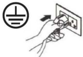
- It is essential that the appliance is connected to an efficient earth system checked by a qualified electrician.
- The use of extension cables is not recommended.
- The air filter should be cleaned at a minimum of once every two weeks.
- Do not place the appliance near any heating appliance.
- The appliance should be transported upright. Any internal water should be emptied before transporting.
- Do not turn the appliance on for at least one hour after transporting it.
- Flammable substances or pressurised containers (aerosol cans) should be kept a minimum of 50cms away from the appliance.
- The appliance should not be installed in rooms containing sulphur, gas or oil.
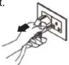
- Do not disconnect the appliance by pulling on the power cable; always disconnect the appliance before any cleaning or maintenance is undertaken.
- Do not store anything on top of the appliance, especially heavy or hot objects.
- Repairs must only be undertaken by authorised service centres. Failure to comply may be dangerous.
- Do not store the appliance covered with plastic bags.
- Remember the environment when disposing of the appliance packaging around the appliance.
- The appliance shall be stored in a well-ventilated area where the room size corresponds to the room area as specified for operation. During storage keep ventilation openings clear of obstruction.
- Cleaning and user maintenance shall not be made by children without supervision.
Additional warnings for appliances with R290 refrigerant gas
(refer to the rating plate located at rear of the appliance for the type of refrigerant gas used).
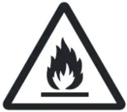
READ THE MANUAL CAREFULLY BEFORE USING THE APPLIANCE

• R290 refrigerant gas complies with European environmental directives.
- This appliance contains approx. 0.086 kg of R290 refrigerant gas. The maximum charge amount is 0.3 kg.
• The minimum rated airflow is 180 m^3/h .
- Use only ingredients recommended by the manufacturer for defrosting or cleaning.
- Do not use the appliance in a room with continuously operating sources of ignition (eg. open flames, an operating gas appliance or an operating electrical heater).
- A surface area greater than 4m^2 is necessary for the installation, use and storage of the appliance.
- Do not pierce or burn the appliance.
- Do not perforate any of the components in the refrigerant circuit.
• Refrigerant gas may be odourless.
- Use care when storing the appliance.
- Stagnation of possible leaks of refrigerant gas in unventilated rooms could lead to fire or an explosion hazard if the refrigerant comes in contact with electric heaters, stoves or other sources of ignition.
- Only persons authorised by an accredited agency certifying their competence to handle refrigerants in compliance with sector legislation should work on refrigerant circuits.
- Maintenance and repairs requiring the assistance of other qualified persons must be carried out under the supervision of specialists in the use of refrigerants.
CAUTIONS
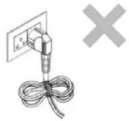
- Do not fold the power cord as shown below.
natural_image
Simple line drawing of a cable being inserted into an electrical outlet, with a gray 'X' symbol nearby (no text or labels)● Make sure the plug is placed fully & firm into the socket.
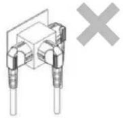
- Do not use multiple sockets as shown below.
natural_image
Pure electrical component diagram without any text, numbers, or symbols● Make sure the plug is clean.
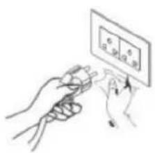
● After turning the unit off, please take plug out of the socket.
natural_image
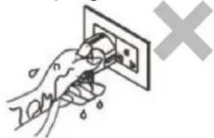
Illustration of hands using a power plug to switch an electrical outlet (no text or symbols)- Do not have wet hands when connecting the power plug.
natural_image
Hand using a power outlet to clean electrical wiring (no text or symbols visible)- If the power cord on this unit is damaged it must be replaced by the manufacturer, it's service agent or qualified persons in order to avoid a hazard.
CAUTIONS
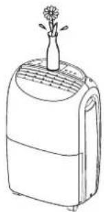
- Do not place anything on top of the control panel.
natural_image
Line drawing of a portable air conditioner with a flower on top (no text or symbols)- Do not place anything over the air inlet or air outlet.
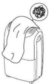
natural_image
Line drawing of a refrigerator with a cloth and a thought bubble showing berries (no text or symbols)- Do not let children play with the unit or control panel.
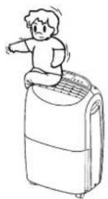
natural_image
Simple line drawing of a child standing on a portable air conditioner unit (no text or symbols)- Do not wet the machine or the control panel.
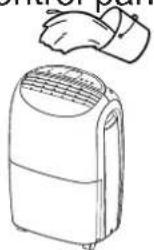
Keep flammable gas/oil away from the machine.
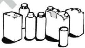
natural_image
Illustration of various plastic containers and bottles (no text or symbols visible)- Ask professionals to do the service and repair.
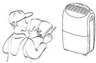
natural_image
Line drawing of a person reading a book next to an air conditioner unit (no text or symbols present)- Do not pull the power cord, which may break and cause danger.
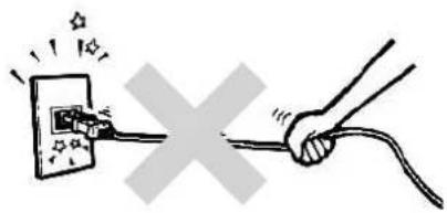
- Do not place the machine on uneven ground. This may cause shaking, noise and leakage of water.
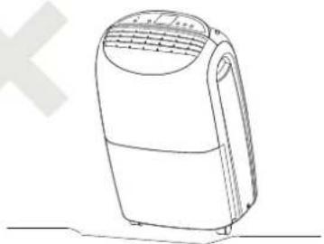
natural_image
Line drawing of a portable air purifier device with ventilation grilles and control panel (no text or symbols)- It is dangerous to put anything into the machine.
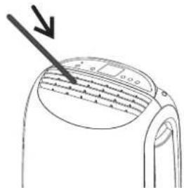
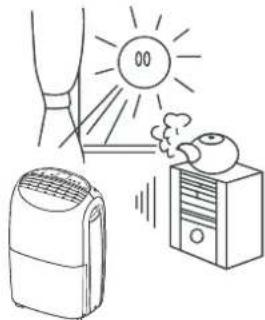
- Keep the machine away from any type of heat sources.
natural_image
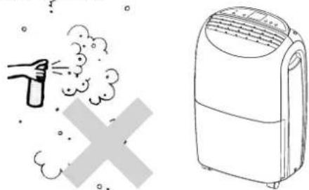
Illustration of a sunlit air conditioner emitting smoke next to a portable heater and a server unit (no text or symbols)- Do not use insect, oil or paint spray around the machine. They might cause damage to the plastic parts or start a fire.
natural_image
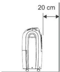
Illustration of a spray gun emitting exhaust smoke next to an air purifier (no text or symbols)- Keep the unit 20cm away from the wall to dissipate the heat properly.
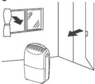
- Close all windows and doors to assist with the efficiency of removing moisture.
natural_image
Diagram showing a refrigerator with airflow direction arrows and an air conditioner unit, next to a door (no text or symbols)DESCRIPTION OF COMPONENTS
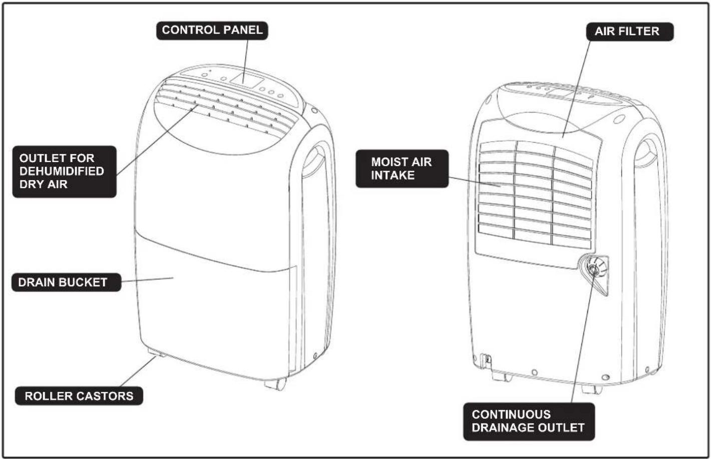
FUNCTION EXPLANATION
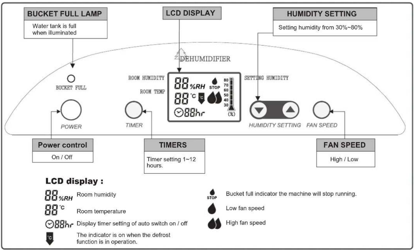
flowchart
graph TD
    A["Bucket FULL LAMP"] --> B["Water tank is full when illuminated"]
    B --> C["Bucket FULL"]
    C --> D["POWER"]
    D --> E["Power control On / Off"]
    F["LCD DISPLAY"] --> G["DEHUMIDIFIER"]
    G --> H["ROOM HUMIDITY ROOM TEMP 88°C 88hr STOP 70-30 (%)"]
    H --> I["TIMER"]
    I --> J["TIMERS"]
    J --> K["Timer setting 1~12 hours."]
    L["HUMIDITY SETTING"] --> M["SETTING HUMIDITY"]
    M --> N["HUMIDITY SETTING"]
    N --> O["FAN SPEED"]
    O --> P["FAN SPEED High / Low"]
    Q["LCD display :"] --> R["Room humidity 88%RH"]
    Q --> S["Room temperature 88°C"]
    Q --> T["Display timer setting of auto switch on / off 88hr"]
    Q --> U["The indicator is on when the defrost function is in operation °C"]
    V["Bucket full indicator the machine will stop running."] --> W["STOP"]
    V --> X["Low fan speed"]
    V --> Y["High fan speed"]
- Start Operation
1) Place the product in an upright position on a flat, steady, stable, heat-resistant surface. Make sure there is nothing flammable or heat sensitive within 100 cm (39 inches). Operating the product in any other position could cause a hazard.
2) Insert the plug into a suitable wall socket. The dehumidifier is suitable for operation on an electricity supply having the same voltage as that shown on its rating label.
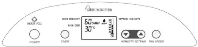
3) Make sure the water tank is correctly located. (After switching on the machine for the first time, if the "Bucket Full" lamp illuminates, just pull out the water tank, check the "float" lever is able to move freely, then return the water tank to the correct position.)
natural_image
Line drawing of a portable air conditioner unit with control panel and indicator lights (no text or symbols)● When Bucket Full Light Is On
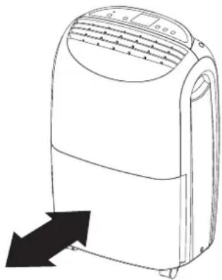
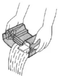
When the water tank is full the machine will stop and the "Bucket Full" light will illuminate. The water tank should be carefully removed from the machine by sliding it outwards from the front of the machine and it should be emptied. When the empty tank is replaced properly into the machine, the machine will start up and run normally.
natural_image
Illustration of hands using a tool to cut or spread material, no text or symbols presentPlease use both hands to carefully empty the water tank.
DEFROST
When operating in low temperatures the surface of the dehumidifier's coil may accumulate ice and effect the efficiency of the dehumidifier. When this happens the machine will go into periodic defrost mode automatically. This is quite normal. Defrost icon 📄 will come on, the compressor will cease operating and the fan will continue to operate until the ice has thawed. As soon as the ice has melted, the compressor will restart and continue the dehumidifying process. Defrost time may vary depending on room temperature and humidity.
CONTINUOUS DRAINAGE OPTIONS
Continuous drainage is an additional method of removing collected water from the dehumidifier. Instead of manually emptying the water tank, the User may choose this method to allow the water to bypass the water tank and flow directly from the dehumidifier via a drain hose. The following steps are useful when there are good conditions for drainage near the dehumidifier.
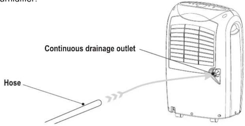
| 1. Prepare hose to drain out water.The hose has inner diameter of 13mm. | Drain hose Back of the unit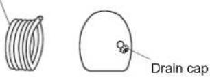 |
| 2. Unscrew drain cap of the drainage outlet and remove soft rubber cover. | 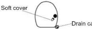 ip ip |
| 3. Connect the drain hose to the drainage outlet. | 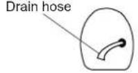 |
INSTALLING DRAINAGE HOSE
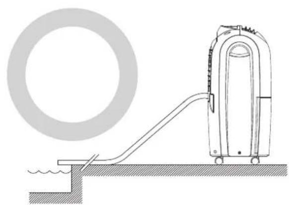
When using continuous drainage, the drain hose must be placed horizontally below the level of the drainage hole. Avoid uneven ground and kinking the hose.
natural_image
Technical line drawing of a vacuum cleaner operating on a platform, with a circular component nearby (no text or symbols)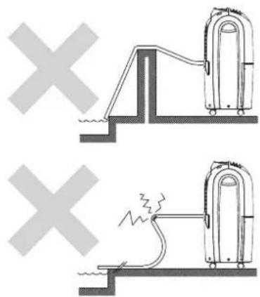
Before cleaning the dehumidifier, first ensure that the appliance is disconnected from the power supply.
1. Outer case:
Wipe the shell with soft, slightly damp cloth. Do not immerse in any liquid. Dry with a dry cloth. Do not use harsh abrasives or solvents.
2. Air filter cleaning:
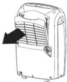
Air filter cleans the dust and impurities from the air which may hinder the dehumidifying function, these should be regularly cleaned. The filter is located behind the rear grill and should be pulled outwards from the top to remove. Clean with a vacuum cleaner or wash it with clean water and dry with a dry cloth. Replace filter and continue to operate the dehumidifier.
natural_image
Line drawing of a portable air conditioner unit with ventilation grilles and a black arrow pointing to the grille (no text or symbols)EMERGENCY
If a problem occurs, switch off and unplug the unit immediately.
For all troubleshooting please contact Ausclimate (www.ausclimate.com.au) and for your own safety do not disassemble the dehumidifier.
INSTRUCTION FOR REPAIRING APPLIANCES CONTAINING R 290
AUTHORISED PERSONS ONLY!
1. Checks to the area
Prior to beginning any authorised work on systems containing flammable refrigerants, safety checks are necessary to ensure that the risk of ignition is minimised. The following precautions shall be complied with prior to conducting work on the system.
2. Work procedure
Work shall be undertaken under a controlled procedure so as to minimise the risk of a flammable gas or vapour being present while the work is being performed.
3. General work area
All maintenance staff and others working in the local area shall be instructed on the nature of work being carried out. Work in confined spaces shall be avoided. The area around the workspace shall be sectioned off. Ensure that the conditions within the area have been made safe by control of flammable material.
4. Checking for presence of refrigerant
The area shall be checked with an appropriate refrigerant detector prior to and during work, to ensure the technician is aware of potentially flammable atmospheres. Ensure that the leak detection equipment being used is suitable for use with flammable refrigerants, i.e. nonsparking, adequately sealed or intrinsically safe.
5. Presence of fire extinguisher
If any hot work is to be conducted on the refrigeration equipment or any associated parts, appropriate fire extinguishing equipment shall be available on hand. Have a dry powder or CO_2 fire extinguisher adjacent to the charging area.
6. No ignition sources
No person carrying out work in relation to a refrigeration system which involves exposing any pipework that contains or has contained flammable refrigerant shall use any sources of ignition in such a manner that is may lead to the risk of fire or explosion. All possible ignition sources, including cigarette smoking, should be kept sufficiently far away from the site of installation, repairing, removing and disposal, during which flammable refrigerant can possibly be released to the surrounding space. Prior to work taking place, the area around the equipment is to be surveyed to make sure that there are no flammable hazards or ignition risks. “No Smoking” signs shall be displayed.
7. Ventilated area
Ensure that the area is in the open or that it is adequately ventilated before breaking into the system or conducting any hot work. A degree of ventilation shall continue during the period that the work is carried out. The ventilation should safely disperse and released refrigerant and preferably expel it externally into the atmosphere.
8. Checks to the refrigerant equipment
Where electrical components are being changed, they shall be fit for the purpose and to the correct specification. At all times, the manufacturer's maintenance and service guidelines shall be followed. If in doubt consult the manufacturer's technical department for assistance.
The following checks shall be applied to installations using flammable refrigerants:
- the charge size is in accordance with the room size within which the refrigerant containing the parts are installed;
- the ventilation machinery and outlets are operating adequately and are not obstructed;
9. Checks to electrical devices
Repair and maintenance to electrical components shall include initial safety checks and component inspection procedures. If a fault exists that could compromise safety, then no electrical supply shall be connected to the circuit until it is satisfactorily dealt with. If the fault cannot be corrected immediately but it is necessary to continue operation, an adequate temporary solution shall be used. This shall be reported to the owner of the equipment so all parties are advised. Initial safety checks shall include:
INSTRUCTION FOR REPAIRING APPLIANCES CONTAINING R 290
AUTHORISED PERSONS ONLY!
- that capacitors are discharged; this shall be done in a safe manner to avoid possibility of sparking.
- that there are no live electrical components and wiring are exposed while charging, recovering or purging the system;
- that there is continuity of earth bonding.
10. Repairs to sealed components
During repairs to sealed components, all electrical supplies shall be disconnected from the equipment being worked upon prior to any removal of sealed covers, etc. If it is absolutely necessary to have an electrical supply to equipment during servicing, then a permanently operating form of leak detection shall be located at the most critical point to warn of a potentially hazardous situation. Particular attention shall be paid to the following to ensure that by working on electrical components, the casing is not altered in such a way that the level of protection is affected. This shall include damage to cables, excessive number of connections, terminals not made to original specification, damage to seals, incorrect fitting of glands, etc.
Ensure that apparatus is mounted securely.
Ensure that seals or sealing materials have not degraded such that they no longer serve the purpose of preventing the ingress of flammable atmospheres. Replacement parts shall be in accordance with the manufacturer's specifications.
NOTE: use of silicon sealant may inhibit the effectiveness of some types of leak detection equipment. Intrinsically safe components do not have to be isolated prior to working on them.
11. Repair to intrinsically safe components
Do not apply any permanent inductive or capacitance loads to the circuit without ensuring that this will not exceed the permissible voltage and current permitted for the equipment in use. Intrinsically safe components are the only types that can be worked on while live in the presence of a flammable atmosphere. The test apparatus shall be at the correct rating. Replace components only with parts specified by the manufacturer. Other parts may result in the ignition of refrigerant in the atmosphere from a leak.
12. Cabling
Check that cabling will not be subject to wear, corrosion, excessive pressure, vibration, sharp edges or any other adverse environmental effects. The check shall also take into account the effects of aging or continual vibrations from sources such as compressors or fans.
13. Detection of flammable refrigerants
Under no circumstances shall potential sources of ignition be used in the searching for or detection of refrigerant leaks. A halide torch (or any other detector using a naked flame) shall not be used.
14. Leak detection methods
The following leak detection methods are deemed acceptable for systems containing flammable refrigerants.
Electronic leak detectors shall be used to detect flammable refrigerants, but the sensitivity may not be adequate, or may need re-calibration. (Detection equipment shall be calibrated in a refrigerant-free area). Ensure that the detector is not a potential source of ignition and is suitable for the refrigerant used. Leak detection equipment shall be set at a percentage of the LFL of the refrigerant and shall be calibrated to the refrigerant employed and the appropriate percentage of gas (25% maximum) is confirmed.
Leak detection fluids are suitable for use with most refrigerants but the use of detergents containing chlorine shall be avoided as the chlorine may react with the refrigerant and corrode the copper pipe-work.
If a leak is suspected, all naked flames shall be removed/extinguished.
If a leakage of refrigerant is found which requires brazing, all of the refrigerant shall be recovered from the system, or isolated (by means of shit off valves) in a part of the system remote from the leak.
INSTRUCTION FOR REPAIRING APPLIANCES CONTAINING R 290
AUTHORISED PERSONS ONLY!
Oxygen free nitrogen (OFN) shall then be purged through the system both before and during the brazing process.
15. Removal and evacuation
When breaking into the refrigerant circuit to make repairs – or for any other purpose – conventional procedures shall be used. However, it is important that the best practise is followed since flammability is a consideration. The following procedure shall be adhered to:
- remove refrigerant;
- purge the circuit with inert gas;
- evacuate;
- purge again with inert gas;
- open the circuit by cutting or brazing.
The refrigerant charge shall be recovered into the correct recovery cylinders. The system shall be “flushed” with OFN to render the unit safe. This process may need to be repeated several times. Compressed air or oxygen shall not be used for this task. Flushing shall be achieved by breaking the vacuum in the system with OFN and continuing to fill until the working pressure is achieved, then venting to atmosphere, and finally pulling down to a vacuum. This process shall be repeated until no refrigerant is within the system. When the final OFN charge is used, the system shall be vented down to atmospheric pressure to enable work to take place. This operation is absolutely vital if brazing operations on the pipe-work are to take place. Ensure that the outlet for the vacuum pump is not close to any ignition sources and there is ventilation available.
16. Charging procedures
In addition to conventional charging procedures, the following requirements shall be followed:
- Ensure that contamination of different refrigerants does not occur when using charging equipment. Hoses or lines shall be as short as possible to minimise the amount of refrigerant contained in them.
- Cylinders shall be kept upright.
- Ensure that the refrigeration system is earthed prior to charging the system with refrigerant.
- Label the system when charging is complete (if not already).
- Extreme care shall be taken to not overfill the refrigerant system.
Prior to recharging the system it shall be pressure tested with OFN. The system shall be leak tested on completion of charging but prior to commissioning. A follow up leak test shall be carried out prior to leaving the site.
17. Decommissioning
Before carrying out this procedure, it is essential that the technician is completely familiar with the equipment and all its details. It is recommended good practice that all refrigerants are recovered safely. Prior to the task being carried out, an oil and refrigerant sample shall be taken in case analysis is required prior to re-use of reclaimed refrigerant. It is essential that electrical power is available before the task is commenced.
a) Become familiar with the equipment and its operation.
b) Isolate system electrically.
c) Before attempting the procedure ensure that:
- Mechanical handling equipment is available, if required, for handling refrigerant cylinders;
- All personal protective equipment is available and being used correctly;
- The recovery process is supervised at all time by a competent person.
- Recovery equipment and cylinder confirm to the appropriate standards.
d) Pump down refrigerant system, if possible.
e) If a vacuum is not possible, make a manifold so that the refrigerant can be removed from various parts of the system.
INSTRUCTION FOR REPAIRING APPLIANCES CONTAINING R 290
AUTHORISED PERSONS ONLY!
f) Make sure the cylinder is situated on the scales before recovery takes place.
g) Start the recovery machine and operate in accordance with manufacturer's instructions.
h) Do not overfill cylinders. (no more than 80% volume liquid charge).
i) Do not exceed the maximum working pressure of the cylinder, even temporarily.
j) When the cylinders have been filled correctly and the process completed, make sure that the cylinders and the equipment are removed from site promptly and all isolation valves on the equipment are closed off.
k) Recovered refrigerant shall not be charged into another refrigerant system unless it has been cleaned and checked.
18. Labelling
Equipment shall be labelled stating that is has been de-commissioned and emptied of refrigerant. The label shall be dated and signed. Ensure that there are labels on the equipment stating the equipment contains flammable refrigerant.
19. Recovery
When removing refrigerant from a system, either for servicing or de-commissioning, it is recommended good practice that all refrigerants are removed safely.
When transferring refrigerant into cylinders, ensure that only appropriate refrigerant recovery cylinders are employed. Ensure that the correct number of cylinders for holding the total system charge are available. All cylinders to be used are designated for the recovered refrigerant and labelled for that refrigerant (i.e. special cylinders for the recovery of refrigerant). Cylinders shall be complete with pressure relief valve and associated shut-off valves in good working order. Empty recovery cylinders are evacuated and, if possible, cooled before recovery occurs.
The recovery equipment shall be in good working order with a set of instructions concerning the equipment that is at hand and shall be suitable for the recovery of flammable refrigerants.
In addition, a set of calibrated weighing scales shall be available and in good working order. Hoses shall be complete with leak-free disconnect couplings and in good condition. Before using the recovery machine, check that it is in satisfactory working order, has been properly maintained and that any associated electrical components are sealed to prevent ignition in the event of a refrigerant release. Consult manufacturer if in doubt.
The recovered refrigerant shall be returned to the refrigerant supplier in the correct recovery cylinder, and the relevant Waste Transfer Note arranged. Do not mix refrigerants in recovery units and especially not in cylinders.
If compressors or compressor oils are to be removed, ensure that they have been evacuated to an acceptable level to make certain that flammable refrigerant does not remain with the lubricant. The evacuation process shall be carried out prior to returning the compressor to the suppliers. Only electric heating to the compressor body shall be employed to accelerate this process. When oil is drained from a system, it shall be carried out safely.
20. Transport of equipment containing flammable refrigerants
Compliance with transport regulations
21. Discarded appliances supplies flammable refrigerants
See national regulations
22. Storage of equipment/appliances
The storage of equipment should be in accordance with the manufacturer's instructions.
23. Storage of packed (unsold) equipment
Storage package protection should be constructed such that mechanical damage to the equipment inside the package will not cause a leak of the refrigerant charge. The maximum number of pieces of equipment permitted to be stored together will be determined by local regulations.
24. Marking equipment using signs
See local regulations.
SPECIFICATIONS
Figures noted, in the contents are for reference only; variation may result due to application in different countries or regions, and shall be based on the best of practical operation.
| Model | WDH-716DE |
| Voltage/Frequency | AC 220-240V~50Hz |
| Rated power consumption | 420 W |
| Capacity | 20 L/D (30°C 80%RH) |
| Refrigerant | R290 / 0.086 kg |
| SAA approval | Certificate No.: TUV-025466-EA |
| Dimensions (W)x(H)x(D) | 362 x 582 x 270 mm |
| Weight | 13 kg |
| Working Temperature | 5°C-32°C |
| Fuse | T.1 A.L 250V |
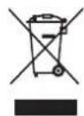
Waste electrical products should not be disposed of with household waste.
Please recycle where facilities exist. Check your local authority of retailer for recycling advice.
Proudly distributed by Ausclimate Pty Ltd
For all enquiries and contact details please visit our website:

- CONTENTS
- READ THE MANUAL CAREFULLY BEFORE USING THE APPLIANCE
- CAUTIONS
- DESCRIPTION OF COMPONENTS
- FUNCTION EXPLANATION
- - Start Operation
- ● When Bucket Full Light Is On
- DEFROST
- CONTINUOUS DRAINAGE OPTIONS
- INSTALLING DRAINAGE HOSE
- Before cleaning the dehumidifier, first ensure that the appliance is disconnected from the power supply.
- Outer case:
- Air filter cleaning:
- EMERGENCY
- INSTRUCTION FOR REPAIRING APPLIANCES CONTAINING R 290
- AUTHORISED PERSONS ONLY!
- Checks to the area
- Work procedure
- General work area
- Checking for presence of refrigerant
- Presence of fire extinguisher
- No ignition sources
- Ventilated area
- Checks to the refrigerant equipment
- Checks to electrical devices
- Repairs to sealed components
- Repair to intrinsically safe components
- Cabling
- Detection of flammable refrigerants
- Leak detection methods
- Removal and evacuation
- Charging procedures
- Decommissioning
- Labelling
- Recovery
- Transport of equipment containing flammable refrigerants
- Discarded appliances supplies flammable refrigerants
- Storage of equipment/appliances
- Storage of packed (unsold) equipment
- Marking equipment using signs
- SPECIFICATIONS
- Proudly distributed by Ausclimate Pty Ltd
Brand : Ausclimate
Model : WDH-070EBP
Category : Humidifier