
Galago UltraPro - Laptop System76 - Free user manual and instructions
Find the device manual for free Galago UltraPro System76 in PDF.


| Product Type | Ultrabook Laptop |
| Brand | System76 |
| Model | Galago UltraPro (galp3) |
| Processor | Intel Core i7-8500U (1.8GHz up to 4.0GHz) or i5-8250U (1.6GHz up to 3.4GHz) |
| Display | 13.3" HiDPI 3200x1800 backlit |
| Memory | Dual-channel DDR4, 2 SO-DIMM slots, up to 32GB, 2133 MHz |
| Graphics | Intel HD Graphics 620 |
| Storage | 1x 2.5" SATA HDD/SSD (7mm) + 1x M.2 2280 SATA/PCIe Gen3 x4 SSD |
| Audio | High Definition Audio, built-in stereo microphone, 2 stereo speakers |
| Webcam | 720p HD USB camera |
| Interfaces | 2x USB 3.0 Type-A, 1x USB-C Thunderbolt 3, 1x HDMI, 1x Mini DisplayPort, 1x RJ-45 Ethernet, 1x headphone-out, 1x mic-in, 1x DC-in, Kensington lock |
| Card Reader | Multi-in-1 (SD/MMC/SDHC/SDXC) |
| Wireless | Intel Dual Band Wireless-AC 8265 (867 Mbps) or 3168 (433 Mbps) + Bluetooth 4.2 |
| Battery | 4-cell 35.3Wh lithium-ion, 40W AC adapter (19V 2.1A) |
| Dimensions | 12.98 x 8.86 x 0.56 in (32.96 x 22.50 x 1.42 cm) |
| Weight | From 2.87 lbs (1.3 kg) |
| Operating System | Ubuntu Linux |
| Security | Kensington lock slot, BIOS password, TPM 2.0 (disabled by default) |
| User-Serviceable Parts | Keyboard, RAM, M.2 SSD, 2.5" drive, CPU fan, heatsink/thermal paste, CMOS battery, internal battery, WiFi/BT module |
| Maintenance | Fan cleaning, thermal paste replacement, BIOS updates via System76 |
Frequently Asked Questions - Galago UltraPro System76
User questions about Galago UltraPro System76
0 question about this device. Answer the ones you know or ask your own.
Ask a new question about this device
Download the instructions for your Laptop in PDF format for free! Find your manual Galago UltraPro - System76 and take your electronic device back in hand. On this page are published all the documents necessary for the use of your device. Galago UltraPro by System76.
USER MANUAL Galago UltraPro System76
natural_image
Laptop displaying a snowy holiday-themed display with Christmas snowflakes, pine branches, and decorative ornaments (no text or symbols visible)System76
Galago Pro (galp3)
Service manual
Revision history
| Author | Date | Version | Remarks |
| Emma Marshall | 2017-11-09 | Initial | |
Contents
Revision history
Hardware overview
External overview
Ports overview
Bottom case screw sizes
Front LED overview
Hardware keyboard shortcuts
External displays
Thunderbolt 3 and eGPU
Internal component overview
User-serviceable parts and repairs
Replacing the keyboard
Steps to replace the keyboard
Photo guide for keyboard replacement
Removing the bottom cover
Steps to remove the cover
Steps to replace the cover
Photo guide for bottom cover removal/replacement
Replacing the RAM
Steps to replace the RAM
Photo guide for replacing the RAM
Replacing an M.2/NVMe SSD
Steps to replace the M.2 drive
Replacing a 2.5" SSD/HDD
Steps to replace the 2.5" drive
Replacing the CPU fan
Steps to replace the CPU fan
Replacing the CPU heatsink/thermal paste
Steps to replace the CPU heatsink/thermal paste
Replacing the CMOS battery
Steps to replace the CMOS battery
Replacing the internal battery
Steps to replace the internal battery
System76 Galago Pro 3 (galp3) Service Manual
Replacing the WiFi/Bluetooth module
Steps to replace the WiFi/Bluetooth module
BIOS utilities
Updating the BIOS
BIOS overview
Main menu
Advanced
Security
Boot
Specifications
Hardware overview
External overview
Ports overview
The Galago provides multiple connectivity options.

Left side overview

Right side overview
Bottom case screw sizes
The Galago has 3 sizes of screws for securing the bottom case.

System76 Galago Pro 3 (galp3) Service Manual
Front LED overview

| Icon | Color | Description |
 | Orange | DC power plugged in |
| Green | Computer is on | |
| Blinking green | Computer is sleeping | |
 | Orange | Battery charging |
| Green | Battery fully charged | |
| Blinking orange | Battery critically low | |
 | Green | Airplane mode is ON(WiFi/Bluetooth disabled) |
 | Green | Hard disk activity |
Hardware keyboard shortcuts
Your Galago has several actions available using the Fn and Function keys.
| Key | Shortcut | Action |
| Fn+F1 | Toggle trackpad | |
| Fn+F2 | Toggle built-in LCD | |
| Fn+F3 | Mute | |
| Fn+F4 | Toggle keyboard backlight | |
| Fn+F5 | Volume down | |
| Fn+F6 | Volume up | |
| Fn+F7 | Toggle displays | |
| Fn+F8 | Brightness down | |
| Fn+F9 | Brightness up | |
| Fn+F10 | Toggle webcam | |
| Fn+F11 | Toggle airplane mode | |
| Fn+F12 | Suspend | |
| ▶/■ | Fn+` | Play/Pause |
| Fn+1 | Toggle fan between max/automatic | |
| Fn+Ins | Num Lock | |
| Fn+Del | Scroll Lock |
External displays
Aside from the standard Mini DisplayPort (MiniDP) and HDMI, the Galago also supports MiniDP over USB-C and external GPU (eGPU) support over Thunderbolt 3.
You can switch between MiniDP or USB-C, but you cannot use both simultaneously.
To switch between MiniDP and USB-C display modes:
- Reboot the Galago and hold the F2 key
- At the Setup Utility, select the Advanced tab
- Select Advanced Chipset Control
- Change the DDI setting according to the table below
- Press F4 to save changes and reboot
| Mode | DDI Setting | Max resolution |
| MiniDP | DDI to MiniDP | UHD-1 (4K, 2160P)3840x2160 @60Hz |
| HDMI | None | UHD-1 (4K, 2160P)3840x2160 @30Hz |
| USB-C to DisplayPort | DDI to TBT | UHD-1 (4K, 2160P)3840x2160 @60Hz |
| USB-C to HDMI | DDI to TBT | UHD-1 (4K, 2160P)3840x2160 @30Hz |
| eGPU over Thunderbolt 3 | DDI to TBT | (Dependent on GPU) |
Thunderbolt 3 and eGPU
Intel Thunderbolt 3 provides a direct link to the processor over PCIe 3.0 x4 at 40Gbps, making it ideal for external GPU (eGPU) support. To use an eGPU, Thunderbolt Security Option must be set to Legacy Mode in the BIOS.
When using an eGPU, the device must be connected prior to powering on and only disconnected after fully powering down. eGPU devices are currently NOT hot-plug capable. Unplugging the device will not damage the Galago or the eGPU, but the system will not work properly until a reboot.
Internal component overview
Below is a color-coded diagram of the Galago's internal components.
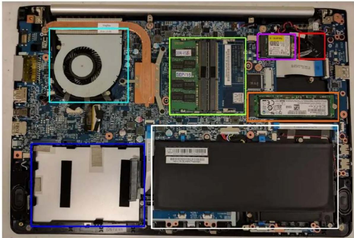
CPU fan is highlighted in cyan
CMOS battery is highlighted in red
RAM is highlighted in green
M.2 SSD is highlighted in orange
Wireless/Bluetooth module is highlighted in purple
2.5" SSD (not present) is highlighted in blue
Battery is highlighted in white
User-serviceable parts and repairs
Many components on your Galago can be upgraded or replaced as necessary. Follow these step-by-step guides for instructions.
Replacing the keyboard
Keyboard replacement is simple and requires only a cross-head screwdriver.
Tools required: Cross-head (Phillips) screwdriver
Time estimate: 10 minutes
Difficulty: Low
Screws: 2 total
- 2 large M2, black (Keyboard M2)
Steps to replace the keyboard
Photos are provided in order below these steps.
- Find a surface suitable for work. A desk or table works well.
- Place something soft on the table, like a towel or anti-static mat.
- Place the Galago lid-side-down.
- Remove the 2 keyboard screws, indicated by the small keyboard icon.
- Open the Galago and place it on its side.
- Push the screwdriver into the keyboard push point until the keyboard pops out.
- Set the Galago down, then starting from the top side, pull the keyboard loose.
- Flip the keyboard over onto the trackpad.
- Pull the large ribbon cable out of the connector.
- The small ribbon cable has a latch. Gently pull the latch from both sides and remove the ribbon cable.
- Remove the keyboard and replace it with the new one.
- Insert the large ribbon cable into the connector.
- Seat the small ribbon cable, then apply pressure equally to both sides of the connector to secure.
- Flip the keyboard over and press the bottom tabs of the keyboard into the case.
- Secure the keyboard by pressing down on the edges of the keyboard.
- Flip the Galago over.
- Replace the 2 screws holding the keyboard in place.
- Boot your Galago and confirm the keyboard is operational.
System76 Galago Pro 3 (galp3) Service Manual
Photo guide for keyboard replacement
- Galago lid-side-down. The 2 keyboard screws are highlighted in red, with the blue highlight indicating the keyboard push point.

- Galago on its side with screwdriver in keyboard push point.

natural_image
Close-up of a silver laptop back panel with a metal screwdriver inserted, showing a small black dot and a pointer pointing to the screen (no text or symbols visible)- Set the Galago down and remove the keyboard starting along the top edge.

natural_image
Close-up of a hand typing on a laptop keyboard with port labels (no readable text or symbols beyond standard port names)- Flip the keyboard over and rest it on the trackpad. Pull the large ribbon cable out of the connector. The smaller ribbon cable has a latch. Gently pull it forward to release the connector, then remove the ribbon cable.

natural_image
Interior view of a laptop case showing internal components including CPU socket, fan, and drive (no readable text or symbols)System76 Galago Pro 3 (galp3) Service Manual
Removing the bottom cover
Removing the cover is required to access the internal components. Prior to removing the cover, ensure the AC power is unplugged, and all peripherals (including SD cards and USB drives) are unplugged or removed from the system.
Tools required: Cross-head (Phillips) screwdriver
Time estimate: 10 minutes
Difficulty: Medium
Screws: 15 total:
- 10 small M2 perimeter, black
- 2 large M2 keyboard, black
- 3 small/short M2 under keyboard, silver
Steps to remove the cover
Photos are provided in order below these steps.
- Find a surface suitable for work. A desk or table works well.
- Place something soft on the table, like a towel or anti-static mat.
- Place the Galago lid-side-down.
- Remove the 10 'perimeter' screws.
- Remove the 2 keyboard screws, indicated by the small keyboard icon.
- Open the Galago and place it on its side.
- Push the screwdriver into the keyboard push point until the keyboard pops out.
- Set the Galago down.
- Starting from the top side, pull the keyboard loose.
- Flip the keyboard over onto the trackpad.
- Remove the 3 silver screws holding the bottom case in place.
- Partially replace the keyboard, but don't snap it into place.
- Close the lid and flip the Galago lid-side-down again.
- The bottom cover will lift off, starting from the front corners working to the back near the hinges.
Steps to replace the cover
- Align the bottom cover to the case towards the back and hinges.
- Set the bottom cover along the edges and confirm the bottom cover is seated.
- Replace the 10 perimeter screws.
System76 Galago Pro 3 (galp3) Service Manual
- Flip the Galago and replace the 3 silver screws from under the keyboard.
- Replace the keyboard by inserting the tabs into the bottom edge near the trackpad and press around the edges of the keyboard to ensure it is fully snapped into place.
- Flip the Galago and replace the 2 keyboard screws.
Photo guide for bottom cover removal/replacement
- Galago lid-side-down. The 10 perimeter screws are highlighted in green. The 2 keyboard screws are highlighted in red, with the blue highlight indicating the keyboard push point.
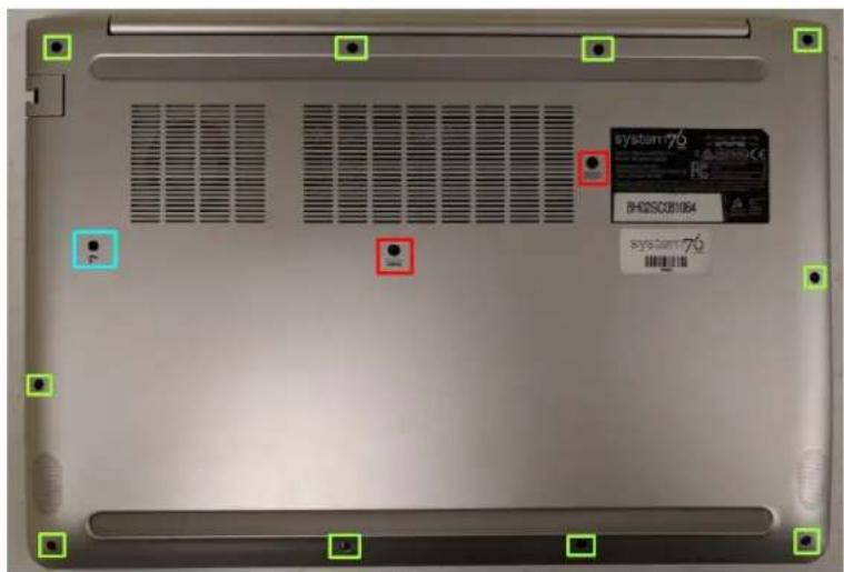
- Galago on its side with screwdriver in keyboard push point. Push until the keyboard has popped out. This requires a solid amount of force.

natural_image
Close-up of a silver computer monitor with a metal screwdriver inserted, showing a black dot on the screen (no text or symbols visible)System76 Galago Pro 3 (galp3) Service Manual
- Once the corner of the keyboard has popped, pull along the top edge of the keyboard to unseat it entirely.

natural_image
Close-up of a hand typing on a laptop keyboard with port labels (no readable text or symbols beyond standard font)- Flip over the keyboard and remove the 3 silver screws. Their location is highlighted in blue. (Note: In this photo, the screws have already been removed.)

natural_image
Top-down view of a laptop's internal circuit board with visible components and connectors (no text or symbols)System76 Galago Pro 3 (galp3) Service Manual
- Set the keyboard mostly in place, close the lid, and flip the Galago lid-side-down.

natural_image
Close-up of a silver laptop keyboard with black keys and ports, no visible text or symbols on the keys or background.- Starting near the front corner, lift the bottom cover off the Galago.

natural_image
Interior view of a smartphone showing the open base, internal circuit board, and top panel (no readable text or symbols)System76 Galago Pro 3 (galp3) Service Manual
Replacing the RAM
RAM acts as temporary storage for your computer. More RAM generally provides better performance. If you've purchased new RAM, need to replace your RAM, or are reseating your RAM, follow these steps.
Tools required: Cross-head (Phillips) screwdriver
Time estimate: 15 minutes
Difficulty: Medium
Steps to replace the RAM
- Follow the steps above to remove the cover.
- Press the small tabs on both sides of the RAM simultaneously.
- Remove the RAM from the slot.
- Insert the new RAM (or reseat the existing RAM) by placing it in the keyed slot and pressing down on the RAM until it clicks into place.
Photo guide for replacing the RAM
- Press the tabs indicated in red to release the RAM from the slot.

System76 Galago Pro 3 (galp3) Service Manual
Replacing an M.2/NVMe SSD
M.2 SSDs offer, at minimum, SATA3 speeds and performance in a package about the size of a stick of gum. NVMe M.2 SSDs offer even higher performance. The Galago supports one M.2 SSD, size 2280, either SATA or PCIe Generation 3.
Tools required: Cross-head (Phillips) screwdriver
Time estimate: 5 minutes
Difficulty: Medium
Steps to replace the M.2 drive
- Follow the steps above to remove the cover.
- Locate the M.2 drive (or drive slot).
- Unscrew the retainer screw opposite the M.2 slot.
- Remove the existing M.2 drive by pulling it out of the slot.
- Insert the new M.2 drive into the slot and hold it in place.
- Replace the retainer screw.
Replacing a 2.5" SSD/HDD
2.5" drives are available as either SSD (Solid State Drive) or HDD (Hard Disk Drive.) SSDs provide much better performance and durability compared to standard HDDs since there are no moving parts. Standard HDDs are less expensive and are useful for storage, however they are much more fragile.
Tools required: Cross-head (Phillips) screwdriver
Time estimate: 5 minutes
Difficulty: Medium
Steps to replace the 2.5" drive
- Follow the steps above to remove the cover.
- Locate the 2.5" SSD (or slot).
- Remove the existing drive by pulling it up and away from the connector.
- Insert the new 2.5" drive.
- Ensure the 2.5" drive is secured in the slot and does not move.
Replacing the CPU fan
If the CPU fan becomes noisy and cleaning it out doesn't fix the issue, you may need a new CPU fan. Contact Support to start a warranty claim or parts purchase.
Tools required: Cross-head (Phillips) screwdriver
Time estimate: 5 minutes
Difficulty: Medium
Steps to replace the CPU fan
- Follow the steps above to remove the cover.
- Locate the CPU fan.
- Unplug the CPU fan from the motherboard.
- Remove the 2 screws holding the CPU fan in place.
- Remove the CPU fan.
- Insert the new CPU fan.
- Replace the 2 screws.
- Plug the new CPU fan into the motherboard.
Replacing the CPU heatsink/thermal paste
In rare cases, or after several years, it may be necessary to apply new thermal paste between the CPU and the heatsink. Thermal paste helps facilitate effective heat transfer between the CPU and the cooling equipment. These instructions can also be used in the unlikely event your heatsink needs replacing.
Tools required: Cross-head (Phillips) screwdriver
Time estimate: 5 minutes
Difficulty: High
Steps to replace the CPU heatsink/thermal paste
- Follow the steps above to remove the cover.
- Locate the CPU heatsink screws.
- Remove the screws, starting with #3, then #2, and lastly #1.
- Carefully remove the heatsink from the case.
- Using a paper towel, remove the existing thermal paste. You may also use a small amount of rubbing alcohol to remove excess or difficult-to-remove paste.
- After cleaning the CPU and heatsink, apply a small line of thermal paste directly onto the CPU core.
- Carefully replace the heatsink.
- Replace the screws, starting with #1, then #2, and lastly #3. Do not fully tighten #1 and #2 until #3 is in place, then fully tighten all screws.
Replacing the CMOS battery
The CMOS battery supplies power to the Galago's CMOS chip. Changes you make to the BIOS and the computer's hardware clock are stored on the CMOS. If your Galago doesn't boot, you can reset the CMOS to force a low-level hardware reset. If your clock is constantly resetting, it's likely your CMOS battery needs replacing.
Tools required: Cross-head (Phillips) screwdriver
Time estimate: 5 minutes
Difficulty: Medium
Steps to replace the CMOS battery
- Follow the steps above to remove the cover.
- Locate the CMOS battery. There is a red and black wire connecting the battery to a white connector.
- Unplug the white connector for 1 minute, then reseat the connector.
- Power up the Galago. The system may power itself off and on after initial boot, this is normal.
- Press Enter at the CMOS/BIOS reset message prompts.
- If you are booted into the BIOS, press F4 to load defaults, then F10 to save and resume normal boot.
Replacing the internal battery
The battery provides primary power whenever the system is unplugged.
Tools required: Cross-head (Phillips) screwdriver
Time estimate: 5 minutes
Difficulty: Medium
Steps to replace the internal battery
- Follow the steps above to remove the cover.
- Unplug the white connector above the battery.
- Remove the 5 screws holding the battery in place.
- Remove and replace the battery.
- Replace the 5 screws and plug in the battery.
Replacing the WiFi/Bluetooth module
Your Galago's WiFi and Bluetooth are both handled with the same module. It is a standard M.2 2230 slot with PCIe & USB Interfaces (A Key).
Tools required: Cross-head (Phillips) screwdriver
Time estimate: 5 minutes
Difficulty: Medium
Steps to replace the WiFi/Bluetooth module
- Follow the steps above to remove the cover.
- Locate the wireless module.
- Gently remove the two antennas by pulling them up and away from the wireless module.
- Remove the retaining screw opposite the M.2 slot.
- Remove the wireless module from the slot.
- Insert the new wireless module.
- Replace the retaining screw.
- Attach the two antennas by aligning the circular fitting and pressing onto the wireless card. The connector will snap into place. Use caution when attaching the connectors, the pins can bend, break, or snap.
BIOS utilities
When starting your Galago, it takes a few seconds to conduct a quick check of the components. As it proceeds, it will notify you if anything is wrong. Any issues that prevent the system from booting will be displayed and you will be prompted to enter the Setup. If no problems are detected, your Galago will load GRUB and then Ubuntu.
For Setup/BIOS, hold F2 while booting.
For boot options, hold F7 while booting and choose your preferred boot device.
Updating the BIOS
BIOS updates and instructions are sent out as needed. System76 will notify you if a BIOS update is available for your Galago.
BIOS overview
The Setup/BIOS utility allows you to make low-level changes to your Galago. It's not recommended to make changes unless the settings are provided by Support, or if you understand what you're changing.
Main menu
| Option | Description |
| SATA Port # | Pressing Enter opens the sub-menu to show the configuration of a SATA device on the SATA ports. |
| OffBoard SATA/NVMe Controller Configuration | Pressing Enter opens the sub-menu to show the configuration of any devices on the offboard SATA/NVMe controller, if installed. |
| System Date/Time | Set the system date/time using the hardware clock. |
| System/Extended Memory | Information on the amount of RAM installed. |
| ME FW/MB Series/BIOS Version/KB/EC Firmware Rev. | Information on the BIOS version(s) and network adapter address. |
Advanced
| Option | Description |
| Advanced Chipset Control | Options for VT-d, FlexiCharger, SGX, Fast Boot, DDI Control |
| >VT-d | Enable/disable Intel Virtualization Technology for Directed I/O. Extends Intel Virtualization Technology (VT) by providing hardware assets for virtual hypervisors. |
| >FlexiCharger | The sub-menu here allows you to enable/disable the FlexiCharger. The FlexiCharger can be set to automatically start charging your battery when the battery reaches a certain capacity level (e.g. you could start the battery charge level at 40%).You can then set the level to stop charging (e.g. 100%), but the stop charge level must be higher than the start charge level. It is not recommended to enable FlexiCharger for extended periods of time. |
| >SW Guard Extensions | Enable or disable Intel SGX (Software Guard Extensions.) |
| >Fast Boot | Enables or disables boot with initialization of a minimal set of devices required to launch the active boot option. This has no effect for BBS boot options. |
| >DDI Control | Determines the Digital Display Interface (DDI) output mode. Can be set to MiniDP (mDP) or Thunderbolt (TBT). |
| Intel(R) Thunderbolt | Options for the Thunderbolt 3 bus. |
| >Thunderbolt Support | Enable or disable support for Thunderbolt 3. |
| >Security Level | Determines if the Thunderbolt port is allowed to send data or only video. Options are Legacy Mode (allow all data transfer), Unique ID or One Time Saved Key, and DisplayPort++ Only. |
| SATA Mode | The SATA (Serial ATA) controller is designed to operate in AHCI (Advanced Host Controller Interface) mode only. |
| Power on boot beep | Enable/disable a beep as the computer starts up. |
| Battery low alarm beep | Enable/disable a beep when the battery is critically low. |
Security
| Option | Description |
| Set Supervisor Password | Sets a password for the Setup Utility. This does not affect access to the computer or Ubuntu, only the BIOS. |
| Set User Password | Sets a password for the Setup Utility. This does not affect access to the computer or Ubuntu, only the BIOS and boot menu. |
| Password on Boot | Specify whether or not a password should be entered to boot the computer. If “Enabled” is selected, only users who enter a correct password can boot the system. The password cannot be reset or cleared if forgotten. |
| Secure Boot | Enables support for Secure Boot. This is not recommended or required for Ubuntu. |
Boot
| Option | Description |
| Boot Option Priorities | Determine the boot order for system devices. Boot option #1 will be tried first. It's recommended to set your boot drive as the 1st option and use the F7 key when temporarily booting from an external device or PXE booting. |
| UEFI Boot | Set options for UEFI (Unified Extensible Firmware Interface) booting. |
| >UEFI Boot | Enable or disable UEFI booting. Disabling UEFI booting will switch the system to Legacy BIOS boot mode. Note that if an EFI-based OS is installed, it will no longer boot in BIOS mode. If a BIOS-based OS is installed, it will no longer boot in UEFI mode. |
| >Network Stack | Enable or disable support for Intel PXE network boot. |
| >Ipv4 PXE Support | Allow PXE booting using IPv4. |
| >Ipv6 PXE Support | Allow PXE booting using IPv6. |
Specifications
| Component | Specification |
| Processors | Intel® CoreTM i7-8500U (2.7GHz)1.8 up to 4.0 GHz - 8MB Cache - 4 Cores - 8 ThreadsIntel® CoreTM i5-8250U (2.5GHz)1.6 up to 3.4 GHz - 6MB Cache - 4 Cores - 8 Threads |
| Display | 13.3" HiDPI 3200 x 1800 Backlit display |
| Memory | Dual Channel DDR4Two 260 Pin SO-DIMM SocketsSupporting DDR4 2133 MHz MemoryModules (real operational frequency depends on the FSB of the processor)Memory Expandable up to 32GBCompatible with 4GB, 8GB or 16GB Modules |
| Graphics | Intel® HD Graphics 620Dynamic FrequencyIntel Dynamic Video Memory Technology |
| Storage | One Changeable 2.5" / 7.0 mm (h) HDD/SSD with SATA (Serial) InterfaceOne M.2 SSD 2280, SATA/PCIe Gen 3*4 Interface |
| Audio | High Definition Audio InterfaceBuilt-In Stereo Microphone2 Stereo Built-In Speakers |
| Touchpad & Keyboard | ClickPad with Multi-Gesture and Scrolling FunctionalityA4 Size Isolated Keyboard |
| Webcam | 720p HD Video Camera Module with USB interface |
| Interfaces | Two USB 3.0 (USB 3.1 Gen 1) Port (Type-A)One USB 3.0 (USB 3.1 Gen 1/Thunderbolt 3) Port (Type-C)One HDMI-Out (High-DefinitionMultimedia Interface) Port (with HDCP)One Mini DisplayPortOne Microphone-In JackOne RJ-45 LAN JackOne DC-In JackOne Headphone-Out Jack |
| Card reader | Embedded Multi-In-1 Card Reader- MMC/ RS MMC- SD/ Mini SD / SDHC/ SDXC |
| M.2 Slots | Two M.2 Card Slots:Slot 1 for M.2 2230 WLAN Combo Module with PCIe & USB Interfaces (A Key)Slot 2 for SSD M.2 2280 Card with SATA / PCIe Gen 3*4 Interface (M Key) |
| Network | Built-In 10/100/1000Mb Base-TX Ethernet LANIntel® Dual Band Wireless-AC 8265(2*2 802.11 a/c) WLAN + Bluetooth M.22230 Combo Module (867Mbps)Intel® Dual Band Wireless-AC 3168(1*1 802.11 a/c) WLAN + Bluetooth M.22230 Combo Module (433Mbps) |
| Power and battery | Full Range AC/DC AdapterAC input 100 - 240V, 50 - 60Hz, DC Output 19V, 2.1A (40 Watts)Embedded 4 Cell Smart Lithium IonBattery Pack 35.3WH |
| Security | Security (Kensington® Type) Lock SlotBIOS PasswordTrusted Platform Module 2.0 (disabled by default) |
| Operating System | Ubuntu Linux |
| Indicators | LED Indicators - Power/Suspend, Battery, HDD, Airplane Mode, Camera |
| Environmental | TemperatureOperating: 5°C - 35°CNon-operating: -20°C - 60°CRelative humidityOperating: 20% - 80%Non-operating: 10% - 90% |
| Dimensions & Weight | 12.98" x 8.86" x 0.56"32.96 x 22.50 x 1.42cm2.87lbs, 1.3kg base weight, varies with configuration. |


- System76
- Galago Pro (galp3)
- Service manual
- Revision history
- Contents
- Hardware overview
- External overview
- Hardware keyboard shortcuts
- External displays
- To switch between MiniDP and USB-C display modes:
- Thunderbolt 3 and eGPU
- Internal component overview
- User-serviceable parts and repairs
- Replacing the keyboard
- Photos are provided in order below these steps.
- Photo guide for keyboard replacement
- Removing the bottom cover
- Steps to remove the cover
- Steps to replace the cover
- Photo guide for bottom cover removal/replacement
- Replacing the RAM
- Steps to replace the RAM
- Photo guide for replacing the RAM
- Replacing an M.2/NVMe SSD
- Steps to replace the M.2 drive
- Replacing a 2.5" SSD/HDD
- Replacing the CPU fan
- Steps to replace the CPU fan
- Replacing the CPU heatsink/thermal paste
- Replacing the CMOS battery
- Steps to replace the CMOS battery
- Replacing the internal battery
- Replacing the WiFi/Bluetooth module
- BIOS utilities
- Updating the BIOS
- BIOS overview
Brand : System76
Model : Galago UltraPro
Category : Laptop