
Quasar CM-6204 - Security Camera FLIR - Free user manual and instructions
Find the device manual for free Quasar CM-6204 FLIR in PDF.


| Product Type | Network HDMI Security Camera |
| Brand | FLIR |
| Model | Quasar CM-6204 |
| Dimensions (L x W x H) | Approx. 70 x 70 x 150 mm |
| Weight | Approximately 500 g |
| Power Supply | 12 V DC / PoE (Power over Ethernet) |
| Power Consumption | Max. 10 W |
| Maximum Resolution | HD 1080p (1920 x 1080) |
| Night Vision | Integrated infrared LEDs, range up to 30 m |
| Viewing Angle | 90° (horizontal) |
| Main Functions | Motion detection, continuous/alarm recording, live streaming, two-way audio (built-in microphone and speaker) |
| Connectivity | Ethernet 10/100, Wi-Fi (optional via adapter) |
| Supported Protocols | TCP/IP, HTTP, RTSP, ONVIF |
| Storage | microSD card up to 128 GB, NAS, NVR |
| Protection Rating | IP66 (weather resistant) |
| Operating Temperature | -20 °C to 50 °C |
| Maintenance and Cleaning | Clean the lens with a soft, lint-free cloth. Avoid solvents. Regularly check connections. |
| Security | SSL/TLS encryption, password protection, IP address filtering |
| Spare Parts and Repairability | Contact FLIR after-sales service for parts. Repairability index not communicated. |
| General Information | User manual available for download at notice-facile.com. Compatible with FLIR and third-party systems. |
Frequently Asked Questions - Quasar CM-6204 FLIR
User questions about Quasar CM-6204 FLIR
0 question about this device. Answer the ones you know or ask your own.
Ask a new question about this device
Download the instructions for your Security Camera in PDF format for free! Find your manual Quasar CM-6204 - FLIR and take your electronic device back in hand. On this page are published all the documents necessary for the use of your device. Quasar CM-6204 by FLIR.
USER MANUAL Quasar CM-6204 FLIR
natural_image
Close-up of a FLIR security camera with lens and control panel (no visible text or symbols beyond brand logo)© 2016 FLIR Systems, Inc. All rights reserved worldwide. No parts of this manual, in whole or in part, may be copied, photocopied, translated, or transmitted to any electronic medium or machine readable form without the prior written permission of FLIR Systems, Inc.
Names and marks appearing on the products herein are either registered trademarks or trademarks of FLIR Systems, Inc. and/or its subsidiaries. All other trademarks, trade names, or company names referenced herein are used for identification only and are the property of their respective owners. This product is protected by patents, design patents, patents pending, or design patents pending. The contents of this document are subject to change.
FLIR Systems, Inc.
6769 Hollister Avenue
Goleta, California 93117
USA
Phone: 888.747.FLIR (888.747.3547)
International: +1.805.964.9797
For technical assistance, please call us at +1.888.388.3577 or visit the Service & Support page at www.flir.com/security.
Important Instructions and Notices to the User:
Modification of this device without the express authorization of FLIR Commercial Systems, Inc. may void the user's authority under FCC rules to operate this device.
Proper Disposal of Electrical and Electronic Equipment (EEE)

natural_image
Simple line drawing of a trash bin with two crossed lines indicating no waste or prohibition (no text or symbols)The European Union (EU) has enacted Waste Electrical and Electronic Equipment Directive 2002/96/EC (WEEE), which aims to prevent EEE waste from arising; to encourage reuse, recycling, and recovery of EEE waste; and to promote environmental responsibility.
In accordance with these regulations, all EEE products labeled with the “crossed out wheeled bin” either on the product itself or in the product literature must not be
disposed of in regular rubbish bins, mixed with regular household or other commercial waste, or by other regular municipal waste collection means. Instead, and in order to prevent possible harm to the environment or human health, all EEE products (including any cables that came with the product) should be responsibly discarded or recycled.
To identify a responsible disposal method nearby, please contact the local waste collection or recycling service, the original place of purchase or product supplier, or the responsible government authority in the area. Business users should contact their supplier or refer to their purchase contract.
Document History
Version Date
2 August 4, 2016
Comment
Initial FLIR release

Table of Contents
1 Document Scope and Purpose .... 1
2 Overview....7
2.1 Features....8
2.2 Package Contents 9
3 Introduction to the CM-620x Mini-Dome IP Camera....11
3.1 Camera Dimensions 11
3.2 Internal Connectors ....11
3.3 Cable Connectors 12
3.3.1 Input and Output Connectors 13
3.3.2 Waterproofing the Camera Cable Connectors 13
3.3.3 Connecting the Unit to the Network 15
3.3.4 Connecting Power to the Camera 15
4 System Requirements....17
5 Installation....19
5.1 Indoor Installation 19
5.2 Outdoor Installation....19
5.3 Initial Camera Configuration 19
5.4 Preparing the Camera for Use....22
5.5 Mounting Instructions....23
5.5.1 Mounting the Camera....23
6 Using the DNA Utility to Search and Access the Camera 25
7 Configuring Communication Settings....27
8 Adjusting and Framing-Up the Camera View 31
9 Configuration and Operation....33
9.1 Browser-Based Viewer Introduction 33
9.2 Live Screen....35
9.3 System Tab....39
9.3.1 System Settings....39
9.3.2 Security 41
9.3.3 Network 50
9.3.4 Events Setup 60
9.3.5 Edge Recording....73
9.3.6 Motion Detection....79
9.3.7 Schedule....83
9.3.8 File Location 84
9.3.9 Maintenance 85
9.3.10 Import/Export 92
9.4 Streaming Tab 93
9.4.1 Video Format....93
9.4.2 Video Compression....103
9.4.3 Video ROI Encoding....106
9.4.4 Video OCX Protocol 107
9.4.5 Video Frame Rate 108
9.4.6 Video Mask....109
9.4.7 Audio 110
9.5 Camera Tab....111
9.5.1 Exposure 112
9.5.2 Picture Adjustment 117
9.5.3 Advanced Picture Settings 118
9.5.4 IR Function 123
9.5.5 Misc....124
9.6 Log Out 125
10 Appendices 127
A.1. CM-6204 Technical Specifications 128
A.2. CM-6208 Technical Specifications 131
A.3. Internet Security Settings....134
A.4. Install UPnP Components....136
A.5. Installing and Deleting the Web Player....138
A.6. Deleting Temporary Internet Files 140
A.7. Mounting Accessories....141
List of Figures
Figure 1: CM-620x Series Camera 7
Figure 2: Package Contents....9
Figure 3: CM-620x Series Camera Dimensions ....11
Figure 4: MicroSD Card Drive and Reset Button....11
Figure 5: CM-620x Camera Input/Output Connections ....12
Figure 6: Camera Cables....13
Figure 7: System Cable....13
Figure 8: System Cable Hose and Wiring....14
Figure 9: RJ45 Connector and Plug....14
Figure 10: Thread-Lock Sealing Nut and RJ45 Connector....14
Figure 11: Loosened Thread-Lock Sealing Nut ....14
Figure 12: RJ45 Connector and Thread-Lock Sealing Nut....15
Figure 13: Fastened Thread-Lock Sealing Nut....15
Figure 14: Discovered IP Devices....20
Figure 15: DNA Assign IP Dialog Box....21
Figure 16: Dome Cover....22
Figure 17: Exposed Mini-Dome Camera....22
Figure 18: Module-Fastening Screw 22
Figure 19: Rotated Lens Assembly....23
Figure 20: Base Plate with Screw Holes....23
Figure 21: Drill Template....23
Figure 22: Windows Firewall Screen 27
Figure 23: Discovered IP Devices....27
Figure 24: DNA Assign IP – Use DHCP Dialog Box....28
Figure 25: DNA Assign IP – Static IP Dialog Box ....28
Figure 26: Login Dialog Box....29
Figure 27: IE Tools > Internet Options > Advanced Window....29
Figure 28: Tilt-Arm Tension Screw on Tensioning Collar ....31
Figure 29: CM-6204 Camera – Pan, Rotate and Tilt Angles ....31
Figure 30: Browser-Based User Interface....33
Figure 31: Live Video Info Dialog Box....35
Figure 32: View Mode Pane....36
Figure 33: System Section Tabs....39
Figure 34: System Screen....40
Figure 35: User Screen 41
Figure 36: Edit User Account Dialog Box....42
Figure 37: HTTPS Screen – Create Self-Signed Certificate....43
Figure 38: Create Self-Signed Certificate Dialog Box....44
Figure 39: Installed Certificate Section 44
Figure 40: Certificate Properties 45
Figure 41: HTTPS Screen – Upload Signed Certificate....45
Figure 42: HTTPS Screen – Install Signed Certificate....46
Figure 43: Create Certificate Request Dialog Box 46
Figure 44: Created Request Subject....47
Figure 45: Certificate Request Properties Dialog Box 47
Figure 46: IP Filter Screen 48
Figure 47: IEEE 802.1X/EAP-TLS Screen....49
Figure 48: Network > Basic Screen ....50
Figure 49: QoS Screen ....52
Figure 50: SNMP Settings Screen ....53
Figure 51: UPnP Screen 55
Figure 52: Direct Access to Camera with UPnP Enabled....55
Figure 53: DDNS Screen 56
Figure 54: Mail Screen – SMTP ....57
Figure 55: FTP Screen....58
Figure 56: HTTP Screen ....59
Figure 57: IO Screen....60
Figure 58: Upload Image by FTP 61
Figure 59: Send HTTP Notification 62
Figure 60: Record Video Clip....62
Figure 61: Upload Image by E-Mail 62
Figure 62: Network Failure Detection Screen....64
Figure 63: Tampering Screen 65
Figure 64: Day/Night Trigger Screen 68
Figure 65: Periodic Event Screen 69
Figure 66: Manual Trigger Screen ....71
Figure 67: SD Card Screen....73
Figure 68: Video File Recording List....74
Figure 69: Selected File Window 75
Figure 70: Network Share Screen....75
Figure 71: Video File Recording List....76
Figure 72: Selected File Window 77
Figure 73: Recording Screen 78
Figure 74: Motion Detection Screen 79
Figure 75: Region Configuration Options....80
Figure 76: Pixel Interval Illustration....81
Figure 77: Schedule Screen....83
Figure 78: File Location Screen 84
Figure 79: Log File Screen....85
Figure 80: User Information Screen – Get User Information 86
Figure 81: User Information – Get User Privacy ......87
Figure 82: Factory Default Screen 88
Figure 83: Partial Restore Screen....89
Figure 84: Software Version Screen 89
Figure 85: Software Upgrade Screen 90
Figure 86: Parameter Screen....91
Figure 87: Import/Export Screen....92
Figure 88: File Download Screen....92
Figure 89: Streaming Section Tabs 93
Figure 90: CM-6204 Video Format Screen 94
Figure 91: CM-6208 Video Format Screen....95
Figure 92: View-1 (Source) 100
Figure 93: View-2 Image Rotated Vertically (Reversed)....101
Figure 94: Video Compression Screen-CM-6204....103
Figure 95: Video Compression Screen-CM-6208....104
Figure 96: Video ROI Encoding Screen....106
Figure 97: Video OCX Protocol Screen 107
Figure 98: Video Frame Rate Screen 108
Figure 99: Mask Screen....109
Figure 100: Audio Screen 110
Figure 101: Camera Section Tabs....111
Figure 102: CM-6208 Exposure Screen 113
Figure 103: Exposure Mode P-Iris Priority Settings....113
Figure 104: Exposure Mode Auto P-Iris Settings....114
Figure 105: Exposure Mode Manual Settings....115
Figure 106: Camera Settings Screen – Picture Adjustment ....117
Figure 107: CM-6208 Advanced Picture Settings Screen – White Balance....118
Figure 108: CM-6208 Advanced Picture Settings Screen – Backlight .....119
Figure 109: Advanced Picture Settings Screen – WDR Function....120
Figure 110: Advanced Picture Settings Screen –Shutter WDR....121
Figure 111: Shutter WDR On....121
Figure 112: Shutter WDR Off....121
Figure 113: Advanced Picture Settings Screen – Noise Reduction....122
Figure 114: IR Function Screen 123
Figure 115: Camera Settings Screen – Digital Zoom 124
Figure 116: Login Message....125
Figure 117: Command Bar Toolbar – Select Internet Options....134
Figure 118: Internet Options Screen....134
Figure 119: Command Bar Toolbar – Internet Options....135
Figure 120: Schedule Screen 135
Figure 121: Quasar Player Installation Wizard ....138
Figure 122: Quasar Player Installation Completed 138

1 Document Scope and Purpose
The purpose of this document is to provide instructions and installation procedures for physically connecting the CM-6204/CM-6208 unit. After completing the physical installation, additional setup and configurations are required before video analysis and detection can commence.

Note:
This document is intended for use by technical users who have a basic understanding of CCTV camera/video equipment and LAN/WAN network connections.
Remarque:
Installation must follow safety, standards, and electrical codes as well as the laws that apply where the units are being installed.
Avertissement:
Users of FLIR products accept full responsibility for ensuring the suitability and considering the role of the product detection capabilities and their limitation as they apply to their unique site requirements.
FLIR Systems, Inc. and its agents make no guarantees or warranties to the suitability for the users' intended use. FLIR Systems, Inc. accepts no responsibility for improper use or incomplete security and safety measures.
Failure in part or in whole of the installer, owner, or user in any way to follow the prescribed procedures or to heed WARNINGS and CAUTIONS shall absolve FLIR and its agents from any resulting liability.
Specifications and information in this guide are subject to change without notice.
A Warning is a precautionary message that indicates a procedure or condition where there are potential hazards of personal injury or death.
A Caution is a precautionary message that indicates a procedure or condition where there are potential hazards of permanent damage to the equipment and or loss of data.
A Note is useful information to prevent problems, help with successful installation, or to provide additional understanding of the products and installation.
A Tip is information and best practices that are useful or provide some benefit for installation and use of FLIR products.
General Cautions and Warnings
This section contains information that indicates a procedure or condition where there are potential hazards.
SAVE ALL SAFETY AND OPERATING INSTRUCTIONS FOR FUTURE USE.
Although the unit is designed and manufactured in compliance with all applicable safety standards, certain hazards are present during the installation of this equipment.
To help ensure safety and to help reduce risk of injury or damage, observe the following:
- The unit's cover is an essential part of the product. Do not open or remove it.
- Never operate the unit without the cover in place. Operating the unit without the cover poses a risk of fire and shock hazards.
- Do not disassemble the unit or remove screws. There are no user serviceable parts inside the unit.
- Only qualified trained personnel should service and repair this equipment.
- Observe local codes and laws and ensure that installation and operation are in accordance with fire, security and safety standards.
Avertissement:
- Do not drop the camera or subject it to physical shock.
- Do not touch sensor modules with fingers. If cleaning is necessary, use a clean cloth with a bit of ethanol and wipe it gently. If the camera will not be used for an extended period of time, put on the lens cap to protect the sensor from dirt.
- Do not aim the camera lens at strong light, such as the sun or an incandescent lamp, which can seriously damage the camera.
- Make sure that the surface of the sensor is not exposed to a laser beam, which could burn out the sensor.
- If the camera will be fixed to a ceiling, verify that the ceiling can support more than 50 newtons (50-N) of gravity, or over three times the camera's weight.
• The camera should be packed in its original packing if it is reshipped.

Caution:
To avoid damage from overheating or unit failure, assure that there is sufficient temperature regulation to support the unit's requirements (cooling/heating). Operating temperature should be kept in the range -40irc to 50ircC (-40° to 122°F), with no more than 90% non-condensing humidity.
Attention:
There are several requirements that should be properly addressed prior to installation at the site. The following specifications are requirements for proper installation and operation of the unit:
- Ambient Environment Conditions: Avoid positioning the unit near heaters or heating system outputs. Avoid exposure to direct sunlight. Use proper maintenance to ensure that the unit is free from dust, dirt, smoke, particles, chemicals, smoke, water or water condensation, and exposure to EMI.
- Accessibility: The location used should allow easy access to unit connections and cables.
- Safety: Cables and electrical cords should be routed in a manner that prevents safety hazards, such as from tripping, wire fraying, overheating, etc. Ensure that nothing rests on the unit's cables or power cords.
- Ample Air Circulation: Leave enough space around the unit to allow free air circulation.
- Cabling Considerations: Units should be placed in locations that are optimal for the type of video cabling used between the unit and the cameras and external devices. Using a cable longer than the manufacturer's specifications for optimal video signal may result in degradation of color and video parameters.
- Physical Security: The unit provides threat detection for physical security systems. In order to ensure that the unit cannot be disabled or tampered with, the system should be installed with security measures regarding physical access by trusted and un-trusted parties.
- Network Security: The unit transmits over IP to security personnel for video surveillance. Proper network security measures should be in place to assure networks remain operating and free from malicious interference. Install the unit on the backbone of a trusted network.
- Electrostatic Safeguards: The unit and other equipment connected to it (relay outputs, alarm inputs, racks, carpeting, etc.) shall be properly grounded to prevent electrostatic discharge.
The physical installation of the unit is the first phase of making the unit operational in a security plan. The goal is to physically place the unit, connect it to other devices in the system, and to establish network connectivity. When finished with the physical installation, complete the second phase of installation, which is the setup and configuration of the unit.
2 Overview
The FLIR Quasar Gen II CM-620x series consists of two camera families: CM-6204 and CM-6208.
The Quasar CM-6204 is an indoor/outdoor, vandal-proof, IP mini-dome camera. The camera provides real-time, QHD H.264 multi-streaming with the highest quality image, supporting up to three simultaneous video streams in H.264 and MJPEG at QHD 1440p, Full HD 1080p, HD 720p, and D1 resolutions. The camera also supports three simultaneous video streams in MJPEG-only at Full HD 1080p, HD 720p, and D1 resolutions. The family consists of two cameras with a motorized varifocal auto-focus, P-Iris lens with True Day/Night and infrared IR illuminator:
• CM-6204-11-I includes a 3-8mm, F1.4 lens with 96-38° horizontal viewing angle
• CM-6204-21-I includes a 7-22mm, F1.4 lens with 42-14° horizontal viewing angle

natural_image
Close-up of a FLIR security camera with lens and control panel (no visible text or symbols beyond logo)Figure 1: CM-620x Series Camera
The Quasar CM-6208 is an indoor/outdoor, vandal-proof, IP mini-dome camera. The camera provides real-time, 4K, H.264 multi-streaming with the highest quality image, supporting four simultaneous video streams at UHD 2160p, Full HD 1080p, HD 720p, and D1 resolutions. The family consists of two cameras with a motorized varifocal auto-focus P-Iris lens with True Day/Night and infrared IR illuminator:
• CM-6208-11-I includes a 3.5-8mm, F1.4 lens with 116-50° horizontal viewing angle
• CM-6208-21-I includes a 9-22mm, F1.4 lens with 45-18° horizontal viewing angle

Caution:
If you are using FLIR's Latitude VMS, we recommend that you configure the camera's settings via the AdminCenter. This is because the camera's web-based interface might be overwritten by Latitude settings. Refer to the Latitude online help for information regarding configuring camera settings.
Attention:
• F1.4 motorized P-Iris lens with auto-focus
- Low-lux mode
• True multi-shutter WDR
• Built-in web application/web server
- Two-way audio
- Edge motion detection
• Detection event driven alarms
- FTP upload
(up to two locations)
• E-mail SMTP alarm notification (up to two e-mails)
- Sequential snapshot numbering
- ONVIF support
• Security IP restricted access allow/deny list
- UPnP support
- Analog video output
- 1/3" (CM-6204) or 1/1.7" (CM-6208) Progressive scan CMOS sensor
• Electronic day/night (ICR)
• 2D/3D/color noise reduction - HTTP streaming MJPEG
- Alarm input-driven events
- Motion detection with region of interest masking
- Tampering detection and notification
- Upload alarm images to FTP
• 128GB microSDXC (Class 10) recording support - SNMP v1/v2/v3 and SNMP traps
- RTSP support
- Multiple users
• Vandal-proof IP66 enclosure -
BNC analog output
-
Three video streams (CM-6204) or four video streams (CM-6208)
• Infrared LED illuminator - Backlight compensation
• H.264 and MJPEG compression - Relay output actions on alarm
- Historical motion detection levels detected/recorded at frame levels
- Dual HTTP notification server support (up to two servers)
- Send images on alarm to e-mail
- Record snapshots to microSDXC card on alarm
- Privacy masks
• Per-user permissions - Group permissions
• Supports PoE/12VDC/24VAC
2.2 Package Contents
Before proceeding, check that the box contains the items listed here. If any item is missing or has defects, do not install or operate the product. Contact your dealer for assistance.
 Mini-dome camera Mini-dome camera | 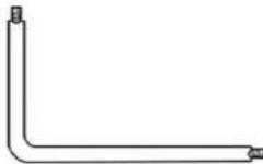 (Torx screw) (Torx screw) |  Rubber washers (×6) Rubber washers (×6) |
 Self-tapping screws (×4)(See note below) Self-tapping screws (×4)(See note below) | 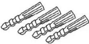 Plastic screw anchors (×4) Plastic screw anchors (×4) |  CD(Bundled software and documentation) CD(Bundled software and documentation) |
 Quick Installation Guide Quick Installation Guide |
Quick Installation Guide
Figure 2: Package Contents

Note:
The self-tapping screws are mainly for softer substrate/material installation such as wood. For other installation materials such as cement ceilings, it is necessary to pre-drill and use plastic anchors before fastening the supplied self-tapping screws into the wall.
Related Documentation
• DNA 2.1 User Manual
• CM-RCSD-G2 Installation Guide
• CM-SMOKE-62 Installation Guide
• CM-BKBX-62 Installation Guide
• CM-CAPX-OUT-P Installation Guide
• CM-4S-62 Installation Guide
• CM-620x Mini-Dome Camera Quick Installation Guide

3 Introduction to the CM-620x Mini-Dome IP Camera
This chapter provides information about the camera hardware for reference before installation. The connectors included on the camera's system cable are described.
- Camera Dimensions
• Internal Connectors - Cable Connectors
3.1 Camera Dimensions
The CM-620x series IP mini-dome camera dimensions are shown below.

Figure 3: CM-620x Series Camera Dimensions
3.2 Internal Connectors
The camera's microSD card drive and Reset button are inside the camera housing.

Figure 4: MicroSD Card Drive and Reset Button
To perform a hard reset to full factory defaults using the Reset button
Insert a pointed object into the Reset button.
Press the button for 30 seconds. Both LEDs on the RJ45 connector are extinguished. After one second, the green network LED flashes once and then remains lighted. The yellow activity LED flashes as soon as it detects network activity. The unit returns to full factory defaults.
3.3 Cable Connectors
The camera is shipped with a system cable for network, power, I/O, and audio connections. The figure below shows the various connectors included in the system cable of the camera. The connectors, pin numbers and signal definitions are listed below.

Figure 5: CM-620x Camera Input/Output Connections
| No. | Cable | Pin | Definition | Remarks | |
| 1 | Ethernet Cable | - | RJ45 connector with LEDs for network and PoE connections. | ||
| 2 | Power (DC 12V*/AC 24V) (3-pin Terminal Block) | 1 | DC 12V - | AC 24V 1 | Power connection |
| 2 | Reserved | GND | |||
| 3 | DC 12V + | AC 24V 2 | |||
| 3 | Alarm I/O (4-pin Terminal Block) | 1 | Alarm In - | Alarm connection | |
| 2 | Alarm In + | ||||
| 3 | Alarm Out - | ||||
| 4 | Alarm Out + | ||||
| 4 | Audio I/O | Green | Audio Out | Two-way audio transmission | |
| Pink | Audio-in/Mic-in | ||||
| 5 | BNC | - | For analog video output | ||
3.3.1 Input and Output Connectors
The alarm input and output connectors are shown below.
| Pin No. | Designation |  |
| 1 | Input (-) | |
| 2 | Input (+) | |
| 3 | Output (-) | |
| 4 | Output (+) |
3.3.2 Waterproofing the Camera Cable Connectors
Follow the instructions below to waterproof the connectors for the different types of cables included in the system cable. The cables are shown below.

natural_image
Coiled black cable with three colored connectors (pink, green, blue) against a plain white background, no text or symbols visible.System Cable

natural_image
Close-up of a black electrical plug with two terminals (no text or symbols visible)RJ45 Cable

natural_image
Close-up of a black electrical plug with a terminal connector (no visible text or symbols)IP66 RJ45 Cable (Optional)
Figure 6: Camera Cables
To waterproof the system cable
- Connect all the required devices to the system cable.
Coat the joints with silicone gel. There should be no gap between the connectors and the cables. For alarm I/O connector and power connector, make sure the side with wires attached is also sealed with silicone gel.

natural_image
Close-up of multiple colored electronic connectors with black wires and green connectors, no text or symbols visibleFigure 7: System Cable
Seal the end of the rubber coating of the system cable as indicated in the figure below. Use enough silicone gel to fill in the hose and wrap around each wire in order to properly waterproof the cable.

natural_image
Close-up of a black cable with exposed wires and a red dashed circle highlighting a section (no text or symbols)Figure 8: System Cable Hose and Wiring
To waterproof the RJ45 cable
- Plug the Ethernet cable to the connector of the RJ45 cable.

natural_image
Close-up of a black electrical plug with a red dashed circle highlighting the connector (no text or symbols visible)Figure 9: RJ45 Connector and Plug
Coat the joint with silicone gel. Make sure there is no gap between the Ethernet cable and the connector in order to properly waterproof the cable.
To waterproof the IP66-Rated RJ45 cable
- Remove the supplied connector from the IP66-rated RJ45 plug.
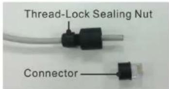
Figure 10: Thread-Lock Sealing Nut and RJ45 Connector
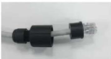
Loosen the thread-lock sealing nut on the IP66-rated RJ45 plug.
natural_image
Close-up of a black and white electrical plug connector (no text or symbols visible)Figure 11: Loosened Thread-Lock Sealing Nut
Thread the Ethernet cable through the thread-lock sealing nut and the IP66-rated RJ45 plug. If the Ethernet cable is already attached to a connector, remove it first.
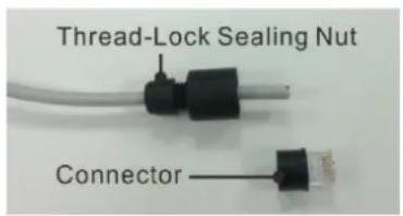
Figure 12: RJ45 Connector and Thread-Lock Sealing Nut
Carefully remove a section of rubber coating from the end of the Ethernet cable to reveal the wires.
Inset the wires into the correct pins of the connector.
Plug the Ethernet cable into the connector of the IP66-rated RJ45 cable.
Fasten the RJ45 plug to the connector of the IP66-rated RJ45 cable.
Tighten the thread-lock sealing nut to the plug.

natural_image
Close-up of a black electrical plug with a cable, no visible text or symbolsFigure 13: Fastened Thread-Lock Sealing Nut
3.3.3 Connecting the Unit to the Network
A Cat 5 Ethernet cable is recommended for network connection. To ensure transmission quality, cable length should not exceed 100 meters (328 feet). Connect one end of the Ethernet cable to the RJ45 connector of the system cable. Plug the other end of the cable into the network switch or PC. Check the status of the link and the activity LEDs. If the LEDs are unlit, check the LAN connection.
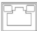
A steady green link LED indicates good network connection.
The yellow activity LED flashes to indicate network activity.
3.3.4 Connecting Power to the Camera
The camera can be powered by Power over Ethernet or by an external 12VDC/24VAC adaptor (not included in the package).
- If using an external power supply, connect the power leads or three-pin power terminal block to the power supply.
- If using PoE, make sure that a Power Sourcing Equipment (PSE) device is used in the network.
Make sure the camera's power cable is properly connected. All electrical work must be performed in accordance with local regulatory requirements.

4 System Requirements
To access the camera via a web browser, ensure that your PC has the proper network connection and meets system requirements as described below.
| Item | Minimum System Requirement |
| Personal Computer | Minimum: Intel® CoreTM i5-2430M @ 2.4 GHz, 4GB RAMRecommended: Intel® CoreTM i7-870 @ 2.93 GHz, 8GB RAM |
| Operating System | Windows XP, Windows 7, Windows 8, Windows 8.1 |
| Web Browser | Microsoft Internet Explorer 9, 10, or 11 |
| Network Card | 10BaseT (10 Mbps), 100Base-TX (100 Mbps), or 1000BaseT (1000Mbps) operation |
| Viewer | ActiveX control plug-in for Microsoft IE |

5 Installation
Follow the instructions below for indoor and outdoor installation of the camera.
Related Links
- Indoor Installation
• Outdoor Installation
- Initial Camera Configuration
• Preparing the Camera for Use
- Mounting Instructions
5.1 Indoor Installation
Read the instructions provided in this chapter thoroughly before installing the camera. Following are additional considerations for indoor installation:
- There must be a fuse or circuit breaker at the starting point of the electrical wiring infrastructure.
- For indoor installations, such as industrial applications, the camera must be protected from hostile external elements (e.g. corrosive environment, metallic dust, extreme temperatures, soot, over spray, etc.).
- Do not place the camera on or near radiators and heat sources.
- All electrical work must be performed in accordance with local regulatory requirements.
5.2 Outdoor Installation
Read the instructions provided in this chapter thoroughly before installing the camera. Following are additional considerations for outdoor installation:
- For outside wiring installation, always use weatherproof equipment, such as boxes, receptacles, connectors, etc.
- For electrical wiring, use the properly rated sheathed cables for conditions to which the cable will be exposed (for example, moisture, heat, UV, physical requirements, etc.).
- Plan ahead to determine where to install infrastructure weatherproof equipment. Whenever possible, ground components to an outdoor ground.
- Use best security practices to design and maintain secured camera access, communications infrastructure, tamper-proof outdoor boxes, etc.
- All electrical work must be performed in accordance with local regulatory requirements.
5.3 Initial Camera Configuration
To perform the initial camera configuration
- Unpack the camera.
- Connect one end of the network Cat 5 Ethernet cable to the RJ45 connector on the camera's system cable.
- Connect the other end of the network cable to a Power Sourcing Equipment (PSE) device, such as a switch.
- Verify that the LEDs on the RJ45 connector illuminate green (indicating a stable network connection) and flashing yellow (to indicate network activity).
5. Do the following:
a. Copy and run dna.exe (see note below) from the included CD.

Note:
Desiccant is included inside the camera housing and must be replaced every time the housing is opened. After desiccants are replaced, reconnect the front housing to the camera as soon as possible. Otherwise, the desiccant will become damp and cannot be used. For instructions on removing the desiccant, refer to the Desiccant User Guide.
b. Click the

c. Select the unit requiring IP assignment.

Figure 14: Discovered IP Devices
d. Right-click the mouse and select the assigned IP address or click the Assign IP button to open the DNA Assign IP dialog box.

Note:
The camera default IP Address and the subnet mask IP Address are automatically supplied by the DHCP server.
e. In the dialog box that is displayed, enter values for the IP Address, Gateway and Netmask.
f. Click Update and wait for OK status to be displayed.

Figure 15: DNA Assign IP Dialog Box
g. Disconnect the Ethernet cable. The camera is ready for deployment (mounting) in a site installation.

Note:
- The camera can be connected to a PC for bench installation via an Ethernet cross-cable.
- The camera default IP Address is automatically set by the DHCP server. If using Latitude, the Address must be set manually.

Tip:
A camera setup adapter, such as Veracity Pinpoint, can be used to connect a laptop directly to the camera when using PoE.
5.4 Preparing the Camera for Use
Before using the camera, you must release the lens assembly, which is in a fixed position for shipping from the factory.
To release the lens assembly for use
- Remove the mini-dome cover by opening the rubber tabs and unscrewing the screws located under the tabs with the Torx screw supplied with the camera.

natural_image
Close-up of a camera lens with two red circular markers highlighting specific components (no text or symbols visible)Figure 16: Dome Cover
Separate the top and bottom sections of the cover in order to access the camera module

natural_image
Close-up of a circular mechanical component with internal layered structure (no visible text or symbols)Figure 17: Exposed Mini-Dome Camera
Unscrew the module-fastening screw sufficiently so that the lens assembly can rotate by 90°.

natural_image
Close-up of a mechanical component with a red circle highlighting a small feature (no visible text or symbols)Figure 18: Module-Fastening Screw
Twist the lens assembly 90irc in either direction in order to verify that the module can easily pan, tilt and rotate in any position.

natural_image
Close-up of a camera module with lens and sensor components (no visible text or symbols)Figure 19: Rotated Lens Assembly
Reinstall the dome cover, replace the screws, tighten them, and snap the rubber tabs back into position.
5.5 Mounting Instructions
To eliminate IR reflection
- Clean the bubble from dirt and finger prints.
- Make sure the bubble has no scratches.
- Fasten the screw that secures the snap-in chassis in order to have the rubber sealed against the bubble.
Avoid aiming the IR where there are nearby objects closer than the scene of interest which might reflect back into the lens.
5.5.1 Mounting the Camera
- Do one of the following:
- For drilled wall or ceiling mounting:
a. Using the supplied template, mark with a pointed pencil the mounting surface through the plate holes where the screw holes need to be drilled. See figures below.

natural_image
Top-down view of a gray dome-shaped object with two red circular markers on its surface and a black connector at the bottom (no text or symbols visible)Figure 20: Base Plate with Screw Holes

Figure 21: Drill Template

Note:
Before marking and drilling the holes, ensure that the base plate alignment is oriented correctly so that the required camera field of view can be achieved when the system is assembled.
b. In the marked locations, drill each hole using a drill bit of a slightly smaller diameter than the supplied screw anchors (molly-plug anchor). You want to achieve a snug insertion so that the plug expansion holds firm after the screws are screwed in.
c. Fully insert the supplied anchors into drilled holes. You may need to tap them flush with the wall using a hammer.
- For installing on a 4S recessed electrical box:
a. Have a qualified installer (check your local electrical codes) rough-in the 4S recessed electrical box and run the wires and power (if not PoE) through the wall/conduits to the box location.
b. Ensure that the box is sufficiently sturdy (attach to the wall stud, ceiling joist, or reinforced surface as needed) to securely hold the weight of the camera.
- For bracket, pole and pendant installations:
a. Feed the system cable through the mounting accessory.

Note:
The power cable is not required if using PoE.

Tip:
Even if you are not using alarm inputs and audio input/output at the time of installation, you may want to consider pre-wiring these connections for future use.
Use shims for shoring up mounts on uneven surfaces.
b. Thread the wires through the base plate and screw it to the pre-drilled wall, ceiling, CM Series Mini-Dome Recessed Mount, CM Series Mini-Dome Corner Mount, or 4S electrical box. Check that the installation is not flimsy, will not wobble, and is flush with the mounting surface.
c. Plug the Cat 5 cable into the camera's Ethernet port and, if needed, plug the power terminal block into the power terminals.
d. If applicable, wire the Alarm In, Alarm Out, Audio In, and Audio Out terminal blocks to external devices. See Cable Connectors (page 11).
e. If needed, connect the other end of the Cat 5 cable to the network and turn on the power from the power supply.

Note:
Do not reassemble the camera's inner cover and mini-dome cover until after hardware configurations and lens adjustments are made.
6 Using the DNA Utility to Search and Access the Camera
The Discovery Network Assistant (DNA) is a user-friendly utility that is designed to easily discover and configure FLIR Professional Security edge devices on a network. The DNA tool has a simple user interface and does not require any installation. The software is provided as a single, standalone executable. It runs on any PC.
DNA provides a central location for listing all the supported FLIR Professional Security camera models accessible over the network. Once listed, each camera can be right-clicked to access and change the network settings. If the network settings are changed for some reason, a new search will relist the units. The units may then be configured via the web interface.
If FLIR's Latitude VMS is being used, configure the unit with a static IP address rather than with DHCP. This ensures that the IP address will not automatically change in the future and interfere with configurations and communication.
The camera must be made accessible for setting network addresses.

Note:
For detailed guidelines about DNA and its usage, refer to the DNA 2.1 User Manual, which is included in the CD provided with the camera.

7 Configuring Communication Settings
To configure communication settings on the camera
- Connect the camera to the network on the same VLAN/LAN as the workstation.
- If the network supports the default, open the DNA utility by running dna.exe which can be
found in the DNA utility folder in the supplied CD, or click the DNA icon

-
In the DNA application, click the DNA button.
-
If the Windows Firewall is enabled, a security alert window pops up.
-
To continue, click Allow Access. Latitude users should consult the Latitude Installation Instructions on disabling the Windows Firewall.
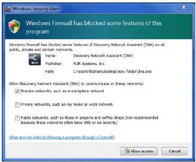
Figure 22: Windows Firewall Screen
- Click Assign IP. All the discovered IP devices will be listed in the screen, as shown in the figure below. The camera's default IP Address is automatically supplied by the DHCP server.

Figure 23: Discovered IP Devices
- Right-click the camera whose network property is to be changed. From the context menu that opens, select Assign IP. The Assign IP dialog is displayed.

Figure 24: DNA Assign IP – Use DHCP Dialog Box
| Tip: Record the camera's MAC address for future reference. |
- To access DNA, do one of the following:
a. For DHCP (not supported by Latitude):
i. Select Use DHCP. Do not use for Latitude.
ii. Click Update and wait for status.
b. For Static IP (recommended for Latitude users):

Figure 25: DNA Assign IP – Static IP Dialog Box
i. Do not select the Use DHCP checkbox. This is recommended for security purposes and for and Latitude users. In the IP Address, Gateway, and Netmask, enter the respective LAN/VLAN (optional DNS) values.
ii. Click Update and wait for OK status to be displayed.
- Right-click and select Web to directly access the camera via a web browser. The web browser opens on the unit's Login dialog box.

Figure 26: Login Dialog Box
- Log into the unit with the default user name Admin and password 1234.

Note:
- Both the user name and password are case-sensitive.
-
It is strongly advised that administrator's password be altered for security reasons.
-
If the User Account Control dialog opens and requests you to install the install.cab file, click Install.
- If the ActiveX installation is not successful after performing the previous step, in the Internet Explorer Tools > Internet Options > Advanced Security settings section, select the "Allow software to run or install even if the signature is invalid" checkbox. Uncheck the checkbox after installing ActiveX. Then click OK.

Figure 27: IE Tools > Internet Options > Advanced Window
- If the existing ActiveX certificate is old or invalid, the ActiveX installation may fail in systems that are not connected to the Internet, which therefore cannot update their security certificates. In this case, the Setup.exe file in the ActiveX folder on the supplied CD should be run. The user can then continue with the installation.
Internet Explorer blocked this website from installing an ActiveX control. What's the risk?
Install
- If a popup message appears for running the ActiveX add-on, click Allow.

Note:
If the password is changed and DVTEL Latitude AdminCenter Discovery feature is in use, deselect all other proprietary types. Select DVTEL Quasar Gen II Series as the Unit Type so that the new password can be configured in the Discovery tab settings.
Additionally, you can change the camera's network properties (either DHCP or Static IP) directly from the camera's web interface on the System > Network > Basic screen.
- Install the web player.

Note:
If you have previously installed a web player application on the PC, you should delete the existing web player from the PC before accessing the camera. For information on how to install the new player, uninstall a previous player, and clear temporary Internet files, see Installing and Deleting the Web Player (page 138).
8 Adjusting and Framing-Up the Camera View
After the camera is connected to the network and running, it is necessary to frame-up the scene and adjust the camera settings to optimize the picture for the individual scenes. If Latitude is being used, consider scheduling different settings for changing ambient conditions throughout the day, week, month or seasons.
To adjust and frame-up the camera view
- In the DNA application, click DNA.
- In the Discovery list, click to select the camera.
- Right-click the context menu and select Web, or enter the camera's IP address in your browser's URL address bar.
- When the browser connects to the camera and prompts for login, do the following:
a) Log in using the default user name Admin and password 1234. If the password has previously been changed, use the new password.
| Note: Both the user name and password are case sensitive. |
b) Allow the ActiveX to download and choose to install the Quasar Web Player.
c) After the unit's web interface opens, use the function buttons on the Home page to adjust the zoom or focus.
Remove the dome cover with the supplied Torx screw.
Use a Phillips screwdriver to loosen the tilt-arm tension screw on the tensioning collar to adjust the camera tilt axis.

Figure 28: Tilt-Arm Tension Screw on Tensioning Collar
If necessary, adjust the rotation, pan and tilt angles as required for the desired view of the scene. When finished, retighten the tilt-arm tension screw.
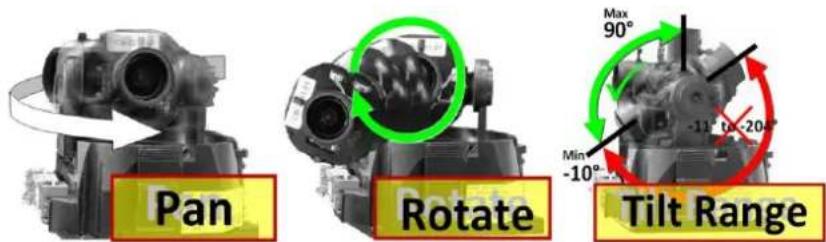
Figure 29: CM-6204 Camera – Pan, Rotate and Tilt Angles

Caution:
To prevent camera damage, do not over extend the tilt range beyond -10irc to 90irc .
Avertissement:
To view greater image detail for more accurate high-definition focusing, on the web-based Viewer home page, right-click the image, click Full Screen, and then check the focus.

Note:
Best focusing results can be achieved when the lens iris is fully open (such as at night in low light). This prevents loss of sharpness if light levels are reduced at night.
Replace the mini-dome cover and tighten the screw.
9 Configuration and Operation
The Quasar Gen II CM series camera is provided with a browser-based configuration interface for video playback and recording. In this chapter, information about system-related settings and camera settings are described in detail.
Additionally, if FLIR's Latitude VMS is used, many of the configurations and features of FLIR's VMS provide configuration and automation of the camera.
This section includes the following information:
- Browser-Based Viewer Introduction
• Live Screen - System Tab
- Streaming Tab
- Camera Tab
- Logout
9.1 Browser-Based Viewer Introduction
The figure below shows the Quasar Gen II CM-620x camera's browser-based user interface.
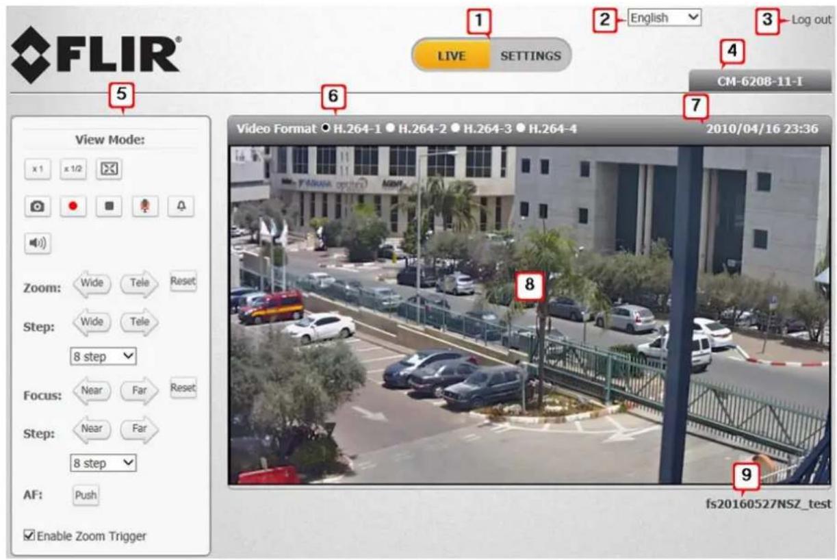
Figure 30: Browser-Based User Interface
The user interface displays the following information:
- The Navigation Bar is displayed in the center of the screen containing Live and Settings buttons.
- Live Button
The Live screen opens by default when the camera logs on. It is used to monitor live video of the targeted area, adjust the display size, take snapshots of the view area, stop/start video streaming, record video in a designated file location, activate or de-activate a loudspeaker (audio function), and to perform a digital zoom. An explanation of the items on the screen is included below and in section 9.2.
- Settings Button
Clicking the Settings button opens the Settings screen, whose sidebar which includes three tabs – System, Streaming, and Camera – that are used for to configure system settings.
- System Settings
The administrator can configure settings for basic system parameters, security, network operation, events, recording, storage, system maintenance, and more. Details are discussed in System Settings.
- Streaming Settings
The administrator can modify video and audio settings on this screen. Details are discussed in Streaming Settings.
- Camera Settings
The administrator can adjust many of the camera settings on this screen, such as Exposure, Picture Adjustment, IR Function, Digital Zoom, and TV System. Details are discussed in Camera Settings.
- The Language Bar is displayed to the right of the Navigation Bar. Supported languages include English, German, Spanish, French, Italian, Japanese, Korean, Portuguese, Russian, Simplified Chinese, and Traditional Chinese.
- The Log out link is located to the right of the Language Bar. Click the Log Out link to exit the application or log into the camera with a different username and password. See Log Out.
- The camera model number is displayed under the Log out link.
- Function buttons are displayed to the left of the Live View window. These are discussed in the following section.
- The video format is displayed and can be selected to the left of the date and time.
- The current date and time are displayed under the model number.
- In the center of the interface is the Live View window, which displays the image that the camera is monitoring.
- The firmware version of the camera is displayed under the Live View window on the right side.
9.2 Live Screen
The camera's Live screen is used to monitor live video. See Figure 30: Browser-Based User Interface. Double-clicking the Live View window opens the Info dialog box, which displays key details about the video stream:

Figure 31: Live Video Info Dialog Box
To view the Live View window in Fullscreen mode
- Right-click the screen.
- Click Fullscreen. The Live View image is displayed in the entire monitor screen.
To exit Fullscreen mode
-
Do one of the following:
-
Press the Escape key on your keyboard. The image is displayed in the Live View window of the Live screen.
- Right-click the screen. Then click Normal view. The image is displayed in the Live View window of the Live screen.
The View Mode pane in the Live screen includes the following function buttons:

Figure 32: View Mode Pane
Full-Window Display

Click this button to view the live video in the full Live Video window.
Half-Window Display

Click this button to view the live video in half of the Live View window.
Full-Screen Mode

Click this button to view the live video on the full screen of your monitor. Click the ESC (Escape) key on your keyboard to exit Full-Screen Mode.
Snapshot

Click this button to automatically save the JPEG snapshots in the specified location. The default location to save snapshots is: C:\To change the storage location, refer to File Location.
Record/Pause


Pressing the Recording button stores recordings from the Live View in the location specified on the local hard drive, which can be configured in the File Location screen. The default storage location for the web recording is: C:/. Refer to File Location for details.
Video Streaming Restart/Stop


Press the Stop button to disable video streaming and to display the live video as black. Press Restart to show the live video again.
Mic


The Microphone button allows the local site to talk to the remote site. Click the button to switch it on/off. This function is available only to a user who has been granted this privilege by the Administrator. Refer to User in the Security section for further details.
Manual Trigger

This button enables you to trigger an action defined on the System > Events Setup > IO screen, which enables control over input and output alarms.
Speaker


Click the Speaker button to mute/activate the audio. This function is available only to a user who has been granted this privilege by the Administrator. Refer to User in the Security section for further details.
Zoom: Wide/Tele


Press the Tele or Wide button to implement continuous zoom adjustment.
Zoom Reset

Press the Reset button to calibrate the camera lens at full wide end.
Step: Wide/Tele


Press the Wide Step or Tele Step button to alternate the zoom between wide and telephoto views within a user-defined range of steps, which can be selected from the drop-down menu shown below.
Step Range
Select from a user-defined range of steps, which can be selected from the drop-down list.
Focus: Near/Far


Press the Near or Far button to implement continuous focus adjustment.
Focus Reset

Press the Reset button to calibrate the camera lens at infinity focus.
Step: Near/Far
Press the Near Step or Far Step button to alternate the focus between near and far views within a user-defined range, which can be selected from the drop-down menu.
Step Range
Select from a user-defined range of steps, which can be selected from the drop-down list.
AF: Push

Click the Push button once to adjust zoom or focus. In this mode, the camera automatically and continuously maintains focus regardless of zoom or view changes. The focus status is displayed above the Live View pane.
Enable Zoom Trigger
When this checkbox is selected, Auto Focus is activated whenever the zoom is adjusted.
9.3 System Tab
The Settings tab in the Navigation Bar opens the sections in the sidebar that are used for configuring the camera. Three sections are available for configuration: System, Streaming, and Camera.

Note:
The System screen is accessible only by the Administrator.
9.3.1 System Settings
The System section includes the following tabs:
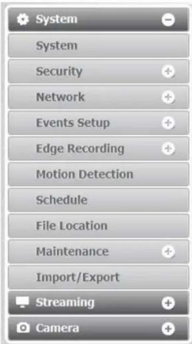
Figure 33: System Section Tabs
- System
• Security
• Network
- Events Setup
- Edge Recording
- Motion Detection
- Schedule
- File Location
- Maintenance
- Import/Export
System Screen
The System screen is used for entering the camera's friendly name and date and time settings. Click the System tab in the sidebar. The System screen is displayed.
![System > System SYSTEM Host Name : QuasarQHDIPCamera Time zone : GMT+00:00 Gambie, Liberia, Morocco, England Enable daylight saving time time offset: 01:00:00 Start date: Jan 1st Sun Start time: 00:00:00 End date: Jan 1st Sun End time: 00:00:00 Time format: yyyy/mm/dd Sync with computer time PC date: 2015/02/10 [yyyy/mm/dd] PC time: 21:43:44 [hh:mm:ss] Manual Date: 2010/04/01 [yyyy/mm/dd] Time: 00:00:00 [hh:mm:ss] Sync with NTP server NTP server: 0.0.0.0 [host name or IP address] Update interval: Every hour SAVE](/content/2026/05/934891/images/0f8f9c4b1960c914bb318049e37808b4022d0e43f391c7c9c7b8c44d66802f32.jpg)
Figure 34: System Screen
The System screen includes the following fields:
Host Name
The host name is for camera identification. If the alarm function is enabled and is set to send an alarm message by Mail or FTP, the host name entered here is displayed in the alarm message. See Events Setup.
Time Zone
Select the time zone from the drop-down menu.
Enable Daylight Saving Time
To enable daylight saving time, check the box and then specify time offset (number of hours or minutes difference between daylight saving time and standard time), start date and time for daylight saving time, and end date and time for daylight saving time. The format for time offset is [hh:mm:ss]. For example, if the amount of time offset is one hour, enter 01:00:00 in the field.
Time format
Enables a choice of formats: either year, month and day (yyyy/mm/dd) or day, month and year (dd/mm/yyyy).
Sync with Computer Time
Select this button to synchronize video date and time display with the PC. You can change the PC date and time in the respective text box.
Manual
The Administrator can set video date and time manually. Entry format should be identical with that displayed to the right of the text box.
Sync with NTP Server
Network Time Protocol (NTP) is an alternate way to synchronize the camera's clock with an NTP server. Enter the network time server host name or IP address to synchronize in the text box. Then select an update interval (every hour, day or week) from the drop-down menu. For further information about NTP, visit www.ntp.org.
Click SAVE when finished.
9.3.2 Security
Clicking the Security tab in the System sidebar opens a drop-down menu with the following screens:
- User
- HTTPS
- IP Filter
- IEEE 802.1X
9.3.2.1 User
The User screen is used for entering and managing user credentials and privileges, as well as configuring authentication settings.

Figure 35: User Screen
Admin Password
Change the administrator's password by entering the new password in both text boxes. The input characters/numbers are displayed as dots for security purposes. After clicking SAVE, the web browser asks the Administrator for the new password (maximum 14 digits).

Note:
The following characters are valid: A-Z, a-z, 0-9,!#\$%&'-.@^\~.
Add user
The user name and passwords are limited to 14 characters. There is a maximum of 20 user accounts.
To add a new user
- Type the new user name and password in the respective fields.
-
Select the appropriate check boxes to give the user Camera Control, Talk and Listen permissions.
-
I/O access – Basic functions that enable you to view video when accessing to the camera.
- Camera control – Allows you to change camera parameters on the Camera tab.
- Talk – Talk allows the user at the local site to talk from the remote site to the administrator
- Listen – Listen allows the user at the local site to listen from the remote site to the administrator.
Click ADD.
Manage User
- To delete a user, click the User name drop-down list and select the user. Click DELETE to remove the user.
- To edit a user, click the User name drop-down list and select the user. Click EDIT to edit the user's password and privileges.

Note:
You must enter the user password and also select the authorized function(s).
![http://192.168.60.222/long1.server_idAccount.html - Internet Explorer http://192.168.60.222/long1.server_idAccount.html User name [User] User password ****** I/O access ✓ Camera control Talk ✓ Listen Save Close 100%](/content/2026/05/934891/images/0883350312015dfbd24be05d8bd74341ded4ac279edc982c9934202978ea0233.jpg)
Figure 36: Edit User Account Dialog Box
- Click Save to modify the account credentials and privileges, or Close to discard changes.
Streaming Authentication Setting
From the drop-down list, select one of the following options:
- Disable – Do not use streaming authentication (default setting).
- Basic – A form of authentication that uses unencrypted base64 encoding. Basic Authentication should generally only be used where transport layer security, such as HTTPS, is provided.
- Digest – A form of authentication used over RTSP in which credentials are encrypted when transmitted.
Click SAVE.
9.3.2.2 HTTPS
To use HTTPS on the camera, an HTTPS certificate must be installed. The HTTPS certificate can be obtained either by creating and sending a certificate request to a Certificate Authority (CA) or by creating a self-signed HTTPS certificate as described below.

Note:
The self-signed certificate does not provide the same level of security as a CA-issued certificate.
HTTPS allows secure connections between the camera and web browser using Secure Socket Layer (SSL) or Transport Layer Security (TLS) to protect camera settings and username/password info. A self-signed certificate or a CA-signed certificate is required to implement HTTPS.
To create a self-signed certificate
Before a CA-issued certificate is obtained, users can first create and install a self-signed certificate. Under the Security category, click the HTTPS tab in the sidebar to display the following screen.

Figure 37: HTTPS Screen – Create Self-Signed Certificate
- On the HTTPS screen, click CREATE under Create Self-Signed Certificate. The Create Self-Signed Certificate dialog box opens.
![http://192.168.50.222/lang1/server_certificate.html - Internet Explorer http://192.168.60.222/lang1/server_certificate.html Create Self-Signed Certificate Country: State or province: Locality: Organization: Organizational Unit: Common Name: Valid days: 365 days[1...9999] OK Cancel](/content/2026/05/934891/images/3bea9294144d72bfe1b8cfbf01e66c6ab80ff85306b7b05d6131e8db7ef78fe5.jpg)
Figure 38: Create Self-Signed Certificate Dialog Box
-
Enter the information in the appropriate field. A definition of each of the required fields follows.
-
Country – Enter a two-letter combination code to indicate the specific country in which the certificate will be used. For instance, type "US" to indicate United States.
• State or province – Enter the local administrative region. - Locality – Enter other geographical information.
- Organization – Enter the name of the organization to which the entity identified in Common Name belongs.
Organizational Unit – Enter the name of the organizational unit to which the entity identified in the Common Name field belongs.
- Common Name – Indicate the name of the person or other entity that the certificate identifies (often used to identify the website).
- Valid days – Enter the period in days (1 \~ 9999) to indicate the valid period of certificate.
Click OK to save the certificate request after completion. The details are displayed in the Subject field of the Installed Certificate section.

Figure 39: Installed Certificate Section
To view the details of the Installed Certificate, click PROPERTIES. The details are displayed in the Certificate Properties dialog box. If you want to remove the certificate, click REMOVE.
| Certificate Properties | |
| Certificate | |
| Version | 2 |
| Serial Number | 0 |
| Signature Algorithm | md5WithRSAEncryption |
| Issuer | C=US, ST=NJ, L=Ridgefiled Park, O=DVTEL Ltd., DU=Technical Writing, CN=TW |
| Validity | |
| Not Valid Before | Apr 6 13:22:49 2010 GMT |
| Not Valid After | Apr 6 13:22:49 2011 GMT |
| Subject | C=US, ST=NJ, L=Ridgefiled Park, O=DVTEL Ltd., OU=Technical Writing, CN=TW |
| Subject Public Key Info | |
| Public Key Algorithm | rsaEncryption |
| RSA Public Key | |
| Modulus (1024 bit) | ab 9c 89 37 ae bb a6 7b 35 7e f1 34 73 5c 00 59 a6 29 9e e4 61 d6 bd d5 e2 83 3e b9 4b df 5f ff d4 9b ca 52 fb 3c c2 fe 75 b5 f6 00 17 f3 f3 fc 8b 5d 55 c1 5b 8b 8b e7 1a 13 5d a8 1a a1 40 ef 83 2d 9c df 02 e7 c0 e1 09 7f 7c e0 7e 5f 7b e0 1c f9 fa bd a3 9c 37 4d 5a 90 c7 7e 3b 84 46 b9 c8 d5 d0 8e 79 c7 41 03 85 b2 2a c4 02 ef a2 f3 19 8b 01 e3 97 3a 3e df e2 40 5a 64 61 c4 7d €1 |
| Exponent | 65537 |
| Signature | |
| Algorithm | md5WithRSAEncryption |
| Signature | 54 f0 f6 bd c1 20 f4 98 24 1a 60 d7 66 ca a6 d4 f9 83 f0 90 36 df ei e3 fe 21 5c 6b 0e 9a 43 fd le e6 bf f4 6a e4 ae 8a df e0 od fb cb 48 Bf 99 64 df c1 c2 9a a9 18 40 f9 fb c5 f1 ec cc f1 b1 o4 gf f3 e2 cd f0 cd f9 fo e9 f1e a9 la e9 af cff20 bf77 dd s1 dd Sb2a43 a3 d4 f5 c7 ie sc74 tc lb f3 f2 f5 ab f165 e267 ea61 |
Figure 40: Certificate Properties
When the signed certificate is returned from the CA, click Browse in the Install Signed Certificate section to locate the file.
Click UPLOAD to install the certificate, as seen in Figure 41.

Figure 41: HTTPS Screen – Upload Signed Certificate
To create a certificate request
- Click CREATE CERTIFICATE REQUEST to create and submit a certificate request in order to obtain a signed certificate from a CA.

Figure 42: HTTPS Screen – Install Signed Certificate
The Create Certificate Request dialog box opens.

Figure 43: Create Certificate Request Dialog Box
-
Enter the information in the appropriate field. A definition of each of the required fields follows.
-
Country – Enter a two-letter combination code to indicate the specific country in which the certificate will be used. For instance, type "US" to indicate United States.
• State or province – Enter the local administrative region. - Locality – Enter other geographical information.
- Organization – Enter the name of the organization to which the entity identified in Common Name belongs.
- Organizational Unit – Enter the name of the organizational unit to which the entity identified in the Common Name field belongs.
-
Common Name – Indicate the name of the person or other entity that the certificate identifies (often used to identify the website).
-
Click OK to save the details of the certificate request after completion. When the request is complete, the subject of the Created Request is displayed in the Subject field

Figure 44: Created Request Subject
- To view details of the Certificate Request, click PROPERTIES below the Subject field. The Certificate Request Properties dialog box opens. If you want to remove the certificate, click REMOVE.
| Certificate Request Properties | |
| Certificate Request | |
| Version | 0 |
| Subject | C=US, ST=NJ, L=Ridgefield Park, O=DVTEL LTD., OU=Technical Writing, CN=TW |
| Subject Public Key Info | |
| Public Key Algorithm RSA Encryption | |
| Modulus (1024 bit) | dd 16 28 4a 92 17 b0 b6 af 6c 33 09 46 c6 dd 32 6e a4 fc 1f 83 fd b2 b3 b6 b6 5b 4d ff 47 59 30 c4 91 4b 52 b1 f3 10 d0 bd e9 e0 2d 1a e4 db c6 fb 6f 50 e2 97 30 5e a3 7f 98 fc 09 39 fb b2 66 1b 93 fe 75 9c 76 86 49 87 73 57 55 4b 24 4f 5f 07 f0 0b e9 40 d2 40 9d 97 76 25 00 c3 93 7f 98 b1 b7 34 fb a2 4f 53 11 21 38 83 70 ef 1f 0b 2a a3 2a 6a 87 cf b8 00 69 33 88 66 26 fd 34 b0 b5 |
| Exponent Attributes | 65537 a0:00 |
| Certificate Request (PEM format) | |
| ----BEGIN CERTIFICATE REQUEST---- MIIBsjCCARsCAQAwcjELMAkGA1UEBhMCVVMxCzAJBgNVBAgMAk5KMRgwFgYDVQQH DA9SaWRnZWZpZWxKIFBhcmsxEzARBgNVBAoMCKRWVEVMIExURC4xGjAYBgNVBAsM EVRIY2huaWNhbCBXcmlOaW5nMQswCQYDVQQDDAJVvZCBnzANBgkqhkiG9w0BAQEF AAOBJQAwgYkCgYEACRYoSpIXsLavbDMJRsbdMm6k/B+D/bKztrZbTf9HWTDEkUtS sfMQ0L3p4C0a5NvG+29Q4pcwXqN/mPwJOfuyZhuT/nWcdoZJh3NXVUskT18H8Avp QNJAnZd2JQDDk3+Ysbc0+6JPUxEhOINw7x8LKqMqaofPuABpM4hmJv00sLUCAwEA AaAAMA0GCSqGSIb3DQEBBAUAA4GBAD9y0UIOdDGIYS79T6grOKWocPwFmSGwgq5T rjpVpEt1jrSKMLIVoa6ue00tyyB6nT2UI8jU3+UjAJwEBL8P84v5S8vo/tkUn1qy 5LTE1kLXkFEOweqDvBIRFVGaj2Oa1IcBQQq+bJXdC358t2y/Fjklo9ONU76e79yK mnhYPIxh ----END CERTIFICATE REQUEST---- | |
Figure 45: Certificate Request Properties Dialog Box
- Copy the PEM-formatted request and send it to your CA.

Note:
The self-signed certificate does not provide the same level of security as a CA-issued certificate.
9.3.2.3 IP Filter
The IP filter restricts access to the camera by denying/allowing specific IP addresses. Click the IP filter tab under the category Security in the sidebar to display the following screen.

Figure 46: IP Filter Screen
To enable the IP filter
- Check the box to enable the IP filter function. Once enabled, the listed IP addresses (IPv4) are allowed or denied access to the camera.
- Select Allow or Deny from the drop-down list.
- Click APPLY to determine the IP filter behavior.
To add or delete an IP address
- Enter the IP address in the Filtered IP Addresses text box.
- Click ADD to add a new filtered address. The Filtered IP Addresses box shows the currently configured IP addresses. Up to 256 IP address entries may be specified.
- To remove an IP address from the list, select the IP address and then click DELETE.
9.3.2.4 IEEE 802.1X
The camera is allowed to access a network protected by 802.1X/EAPOL (Extensible Authentication Protocol over LAN). Users must contact the network administrator to obtain certificates, user IDs, and passwords.

Figure 47: IEEE 802.1X/EAP-TLS Screen
CA Certificate
The CA certificate is created by the Certificate Authority for the purpose of validating itself. Click Browse to locate the file and UPLOAD to upload the certificate to check the server's identity.
Client Certificate
Upload the Client Certificate to authenticate the camera. Click Browse to locate the file and UPLOAD to upload the certificate.
Private Key
Upload the Private Key to authenticate the camera. Click Browse to locate the file and UPLOAD to upload the private key.
Settings
- Identity – Enter the user identity (user name) associated with the certificate. Up to 16 characters can be used.
- Private Key Password – Enter the password associated with the user identity. Up to 16 characters can be used.
- Enable IEEE 802.1X – Select the checkbox to enable IEEE 802.1X security. The setting is disabled by default.
Click SAVE to save the IEEE 802.1X/EAPTLS setting.
9.3.3 Network
From the System screen, click the Network tab.
The following screens are available from the Network tab:
- Basic - QoS - SNMP - UPnP - DDNS - Mail - FTP - HTTP
9.3.3.1 Basic
The Basic screen is used to configure the camera's basic network settings.

Figure 48: Network > Basic Screen
It is possible to connect to the camera with either fixed or dynamic (DHCP) IP address. The camera also provides PPPoE (Point-to-Point Protocol over Ethernet) support for users who connect to the network via PPPoE.
The Basic screen is divided into three sections: General, Advanced and IPv6 Configuration.
General
Select one of the following options in the General area for configuring network settings:
- Get IP address automatically
- Use fixed IP address
- User PPPoE
Get IP address automatically
If you select Get IP address automatically, you can use the DNA utility, which is provided in the supplied CD, to obtain the IP address from a DHCP server on the network. See Using the DNA Utility to Search and Access the Camera.

Note:
For future reference, record the camera's MAC address, which is found on the camera label.
Use fixed IP address
The camera's default setting is Use fixed IP address. Refer to Using the DNA Utility to Search and Access the Camera for login with the default IP address. You may use DNA or enter the IP address in your Internet browser's URL address bar.
To set up a new static IP address
- Select the Use fixed IP address option.
-
Enter the following information:
-
IP address – The IP address is necessary for network identification.
- Subnet mask – Used to determine if the destination is in the same subnet. The default value is 255.255.255.0.
- Default gateway – Used to forward frames to destinations in a different subnet. An invalid gateway setting causes transmission to destinations in other subnets to fail.
- Primary DNS – The primary domain name server that translates host names into IP addresses.
• Secondary DNS – A secondary domain name server that backs up the primary DNS.
To use PPPoE
- Enter your PPPoE user name and password into the respective fields.
- Click SAVE to confirm the settings.
Advanced
Enter the following advanced parameters in the Advanced section of the screen:
- Web Server port – The default web server port is 80. Once the port is changed, the user must be notified the change for the connection to be successful. For instance, when the Administrator changes the HTTP port of the camera whose IP address is 192.168.0.100 from 80 to 8080, the user must type in the web browser http://192.168.0.100:8080 instead of http://192.168.0.100.
- RTSP port – The default setting of the RTSP port is 554. The range is from 1024 to 65535.
- MJPEG over HTTP port – The default setting of MJPEG over HTTP port is 8008. The range is from 1024 to 65535.
- HTTPS port – The default setting of HTTPS port is 443. The range is from 1024 to 65535.
- MTU – The MTU (Maximum Transmission Unit) is the greatest amount of data that can be transferred in one physical frame on the network. For Ethernet, the MTU is 1500 bytes (default setting). For PPPoE, the MTU is 1492. The range is from 700 to 1500 bytes.

Note:
Be sure to assign a different port number for each service mentioned above.
Click SAVE to save the settings.
IPv6 Address Configuration
IPv6 is not supported.
9.3.3.2 QoS
QoS (Quality of Service) provides differentiated service levels for different types of traffic packets and guarantees delivery of priority services during periods of network congestion. Adapting the Differentiated Services (DiffServ) model, traffic flows are classified and marked with DSCP (DiffServ Code point) values, and as a result receive the corresponding forwarding treatment from DiffServ-capable routers. DSCP configuration settings are entered in the System > Network > QOS screen:

Figure 49: QoS Screen
DSCP Settings
The DSCP value range is from 0 to 63. The default DSCP value is 0 (DSCP disabled). The camera uses the following QoS classes: Video, Audio, and Management.
- Video DSCP – This class consists of applications such as MJPEG over HTTP, RTP/RTSP and RTSP/HTTP.
• Audio DSCP – The camera supports audio. - Management DSCP – This class consists of HTTP traffic (web browsing).
Click SAVE when complete.

Note:
To enable this function, make sure the switches/routers in the network support QoS.
9.3.3.3 SNMP Settings
The Simple Network Management Protocol (SNMP) enables the camera to be monitored and managed remotely by the network management system. SNMP configuration settings are entered in the System > Network > SNMP screen.

Figure 50: SNMP Settings Screen
SNMP v1/v2
- Enable SNMP v1 or Enable SNMP v2 – Select the version of SNMP (v1 or v2) to use by checking the relevant box.
- Read Community – Specify the community name that has read-only access to all supported SNMP objects. The default value is public.
- Write Community – Specify the community name that has read/write access to all supported SNMP objects (except read-only objects). The default value is private.
SNMP v3
SNMP v3 provides important security features including:
- Confidentiality – Encryption of packets to prevent snooping by an unauthorized source.
- Integrity – Message integrity to ensure that a packet has not been tampered with in transit including an optional packet replay protection mechanism.
- Authentication – To verify that the message is from a valid source.
To enable the SNMP v3 protocol, enter the appropriate data and passwords requested:
- Enable SNMP v3 – Select the checkbox.
• Security Name – See note below. - Authentication Type – Select MD5 or SHA from the drop-down list. See note below.
- Authentication Password – See note below.
- Encryption Type – Select DES or AES from the drop-down list. See note below.
- Encryption Password – See note below.

Note:
You may have to consult with your System Administrator to activate this function.
Traps for SNMP v1/v2/v3
Traps are used by the camera to send messages to a management system for important events or status changes.
- Enable traps – Check this box to activate trap reporting.
- Trap address – Enter the IP address of the management server.
- Trap community – Enter the community to use when sending a trap message to the management system. The default value is public.
- Trap Option
- Warm start – A warm start SNMP trap signifies that the SNMP device, such as the camera, performs a software reload.
Click SAVE when complete.
9.3.3.4 UPnP
The System > Network > UPnP screen enables the Universal Plug-and-Play protocol on your network devices.

Figure 51: UPnP Screen
UPnP Settings
- Enable UPnP – If UPnP is enabled and a camera is discovered on the LAN, the icon of the connected camera appears in My Network Places, allowing direct access, as seen below.

Figure 52: Direct Access to Camera with UPnP Enabled

Note:
To enable this function, make sure the UPnP component is installed on your computer. Refer to Install UPnP Components for the Windows 7, 8, 8.1, and 10 procedures.
- Enable UPnP port forwarding – When UPnP port forwarding is enabled, the camera is allowed to open the web server port on the router automatically.

Note:
To enable this function, make sure that your router supports UPnP and that it is activated.
- Friendly name – Enter the name for the camera for identification.
Click SAVE to save the settings.
9.3.3.5 DDNS
Dynamic Domain Name System (DDNS) allows a host name to be constantly synchronized with a dynamic IP address. This permits those using a dynamic IP address to be accessed by a static domain name. DDNS configuration settings are entered in the System > Network > DDNS screen:

Figure 53: DDNS Screen
To use DDNS
- Select the Enable DDNS checkbox.
- From the Provider drop-down list, select a DDNS host provider name.
- In the Host name text box, enter the registered domain name.
- In the Username/E-mail text box, enter the username or e-mail address required by the DDNS provider for authentication.
- In the Password/Key text box, enter the password or key required by the DDNS provider for authentication.
- Click SAVE to save the setting.
9.3.3.6 Mail
Simple Mail Transfer Protocol (SMTP) is a protocol for sending e-mail messages between servers. It is a relatively simple, text-based protocol, where a text message is transferred to one or more specified recipients. The Administrator can send an e-mail via Simple Mail Transfer Protocol (SMTP) when an alarm is triggered. E-mail notifications are set by selecting the checkbox for an e-mail-related triggered action on the IO, Network Failure Detection, Tampering, Periodic Event, Manual Trigger, and Motion Detection screens.
SMTP (E-mail) server configuration settings are entered in the System > Network > Mail screen:

Figure 54: Mail Screen – SMTP
Two SMTP server accounts can be configured with or without SSL encryption. Enter the settings for the 1 st SMTP server and 2 nd SMTP server in the appropriate fields. Settings include SMTP server, server port (the default port is 25), account name, password, and recipient e-mail address settings. To encrypt e-mail with SSL, select the 1 st SMTP SSL and/or 2 nd SMTP SSL checkbox. For SMTP server details, contact your network service provider. Click SAVE when finished.
9.3.3.7 FTP
The Administrator can send an alarm message to one or two File Transfer Protocol (FTP) sites when motion is detected. FTP notifications are set by selecting the checkbox for an FTP-related triggered action on the IO, Network Failure Detection, Tampering, Periodic Event, Manual Trigger, and Motion Detection screens.
For each server, enter the server IP address, server port number, user name, password, and remote folder path. Settings are entered in the System > Network > FTP screen:

Figure 55: FTP Screen
To use passive mode, select the 1st FTP passive mode or 2nd FTP passive mode checkbox for the respective server. In passive mode, FTP the client initiates both connections to the server, solving the problem of firewalls filtering the incoming data port connection to the client from the server.
In order to support passive mode FTP on the server-side firewall, the following communication channels must be opened:
- FTP server's port 21 from anywhere (client initiates connection)
- FTP server's port 21 to ports > 1023 (server responds to client's control port)
- FTP server's ports > 1023 from anywhere (client initiates data connection to random port specified by server)
- FTP server's ports > 1023 to remote ports > 1023 (server sends ACKs and data to client's data port)
Click SAVE when finished.
9.3.3.8 HTTP
An HTTP notification server detects notification messages of triggered events sent from cameras. HTTP notifications are set by selecting the Send HTTP notification checkbox on the IO, Tampering, Manual Trigger, and Motion Detection screens.
Two notification server accounts (Alarm Triggered and Motion Detection) can be set up and sent to the specified HTTP servers. For each server, enter the HTTP details, including server IP address, user name, and password. Settings are entered in the System > Network > HTTP screen:

Figure 56: HTTP Screen
Click SAVE when finished.
9.3.4 Events Setup
The Events Setup tab includes the following screens:
- IO - Network Failure Detection - Tampering - Day/Night Trigger - Periodic Event - Manual Trigger
9.3.4.1 IO
The IO screen is used to control input and output alarms and messages, which are generated when an event is recognized by the system.

Figure 57: IO Screen
Alarm Switch
The Administrator can select from the following options:
- Select Off to disable an alarm.
- Select On to enable an alarm (default setting).
- Select By Schedule to set a schedule. Then click Please Select to select up to 10 schedules from the drop-down list that opens. The selected schedules are displayed in the Please Select text box. To set a schedule, open the Schedule tab.
Click SAVE after configuring the settings.
Alarm Type
Select an alarm type (Normal close or Normal open) that corresponds to the alarm application. Normal open is the default setting. Click SAVE after configuring the settings.
Alarm Output
Define the normal alarm output signal as Output high or Output low, according to the current alarm application. Output high is the default setting. Click SAVE after configuring the settings.
Trigger Action
The Administrator can specify various alarm actions to take when an alarm is triggered. The following options are available:
- Enable alarm output – Select this checkbox to enable alarm relay output. The checkbox is not selected by default.
- Send message by FTP – Select the checkbox send an alarm message by FTP when an alarm is triggered.
- Upload image by FTP – Select this box to assign an FTP site and configure the parameters shown. When an alarm is triggered, event images are uploaded to the designated FTP site.

Note:
Images can be sent by FTP only when MJPEG is selected as the video stream from the Video Format screen.
Follow these steps:
• From the FTP address drop-down list, select one of the two FTP addresses to use.
- From the Pre-trigger buffer and Post-trigger buffer drop-down lists, select the number of frames for the buffer from 1-20 frames.
√ Upload image by FTP
FTP address
FTP1
Pre-trigger buffer
5 frames
Post-trigger buffer
5 frames

Continue image upload

Upload for 1 sec

Upload while the trigger is active
Image frequency

fps
Figure 58: Upload Image by FTP
- Select the Continue image upload checkbox to upload an image by FTP for a defined period of time or while the trigger is active. Select one of the following options:
- To specify the length of time for the upload, select Upload for and enter the number of seconds in the text box.
• To upload while the trigger is active, select Upload while the trigger is active.
In the Image Frequency text box, from the drop-down list select the number of frames per seconds from 1-15 for the upload.

Note:
Make sure that FTP configuration has been completed. See FTP for details.
- Send HTTP notification – Select this checkbox to send a notification by HTTP. Select the destination HTTP address from the drop-down menu and specify the parameters for event notifications by the IO event triggered. When an alarm is triggered, the notification will be sent to one of two specified HTTP servers. See figure below.

Figure 59: Send HTTP Notification
- Record video clip – Select this box in order to save the alarm-triggered recording to your microSDXC card or to the NAS. Enter the number of seconds for the pre-trigger buffer. Select the first radial button if you wish to upload for a specified length of time and enter the number of seconds. Alternatively, select the second radial button to upload while the trigger is active.

Figure 60: Record Video Clip

Note:
In order to use this function, make sure that local recording with a microSDXC card is activated and that the NAS is properly configured. See Recording for further details.
- Send message by E-Mail – Select the checkbox send an alarm message by e-mail when an alarm is triggered. The e-mail address is entered in the Mail screen.
- Upload image by E-Mail – Select this checkbox to assign an e-mail address for sending the image captured by a triggered alarm. The e-mail address is entered in the Mail screen.

Note:
Images can be sent by e-mail only when MJPEG is selected as the video stream from the Video Format screen.
• From the E-Mail address drop-down list, select one of the two e-mail addresses.
- From the Pre-trigger buffer and Post-trigger buffer drop-down lists, select the number of frames for the buffer from 1-20 frames.
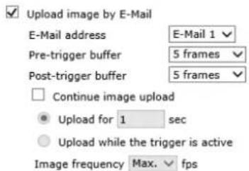
Figure 61: Upload Image by E-Mail
- Check the Continue image upload box if you wish to upload an image by e-mail for a defined period of time or while the trigger is active. Select one of the following options:
- To specify the length of time for the upload, select Upload for and enter the number of seconds in the text box.
• To upload while the trigger is active, select Upload while the trigger is active.
In the Image Frequency text box, from the drop-down list select the number of frames per seconds from 1-15 for the upload.

Note:
Make sure that SMTP configuration has been completed. See Mail for details.
Click SAVE after configuring the settings.
File Name
- File Name – Enter a file name in the field, for example image.jpg. The uploaded image's file name format is set in this section. Select one that meets your requirements.
- Add date/time suffix (default setting) File name: imageYYMMDD_HHNNSS_XX.jpg Y: Year, M: Month, D: Day H: Hour, N: Minute, S: Second X: Sequence Number
- Add sequence number suffix (no maximum value) File name: imageXXXXXXXX.jpg X: Sequence Number
- Add sequence number suffix (limited value) File Name: imageXX.jpg X: Sequence Number
The file name suffix ends at the number being set. For example, if the setting is up to "10," the file name will start from 00, end at 10, and then start over again.
- Overwrite The original image in the FTP site will be overwritten by the new uploaded file with a static filename.
Click SAVE after configuring the settings.
9.3.4.2 Network Failure Detection
Settings on the Network Failure Detection screen enable the camera to periodically ping another IP device within the network to detect a network failure, for example, if a video server is disconnected. By implementing local recording through a microSDXC card, the camera can operate as a backup recording device for the surveillance system if network communication is lost due to a network failure.

Figure 62: Network Failure Detection Screen
Detection Switch
The Administrator can select from the following options:
- Select Off to disable an alarm (default setting).
- Select On to enable an alarm.
- Select By Schedule to set a schedule. Then click Please Select to select up to 10 schedules from the drop-down list that opens. The selected schedules are displayed in the Please Select text box. To set a schedule, open the Schedule tab.
Click SAVE after configuring the settings.
Detection Type
In the text box, enter the IP address to ping and the time interval (in minutes) between pings. Click SAVE after configuring the settings.
Triggered Action
The Administrator can specify various alarm actions to be taken when an alarm is triggered. The options are listed below.
- Enable alarm output – Check this box and select the predefined type of alarm output (low or high) to enable alarm relay when a network failure is detected.
- Send message by FTP – Select whether to send an alarm message by FTP when a network failure is detected.
- Record video clip – Select this box in order to save the alarm-triggered recording into a microSDXC card or the NAS. Enter the number of seconds for the pre-trigger buffer. Select the first radial button to upload for a specified length of time and enter the number of seconds. Alternatively, select the second radial button to upload while the trigger is active. See Figure 60: Record Video Clip.

Note:
In order for this function to be implemented, make sure that local recording with a microSDXC card is activated and that the NAS is properly configured. See Recording for further details.
- Send message by E-Mail – Select whether to send an alarm message by e-mail when a network failure is detected.
Click SAVE to save the network failure detection settings.
9.3.4.3 Tampering
The Tampering screen enables the camera to deal with tampering (such as blocking, paint-spraying, and obscuring the lens, etc.). Using video analysis, the camera can react to such events by sending notifications or uploading snapshots to the specified destination(s).
![System > Events Setup > Tampering TAMPERING ALARM ○ off ● On ○ By schedule Please select ... TAMPERING DURATION Minimum duration 20 sec Sensitivity level [1-100] 60 TAMPERING ACTION □ Enable alarm output high ▼ □ Send message by FTP □ Upload image by FTP □ Send HTTP notification File NAME File name : image.jpg ● Add date/time suffix ○ Add sequence number suffix (no maximum value) ○ Add sequence number suffix up to 0 and then start over ○ Overwrite SAVE](/content/2026/05/934891/images/b94417ca02f08a446becd498471ae2648193d02c8aedeae73f398ee08c661ca4.jpg)
Figure 63: Tampering Screen
Detection of camera tampering is achieved by measuring the differences between the older frames of video (which are stored in buffers) and more recent frames.
Tampering Alarm
The Administrator can select from the following options:
- Select Off to disable the tampering alarm (default setting).
- Select On to enable the tampering alarm.
- Select By Schedule to set a schedule. Then click Please Select to select up to 10 schedules from the drop-down list that opens. The selected schedules are displayed in the Please Select text box. To set a schedule, open the Schedule tab.
Click SAVE after configuring the settings.
Tampering Duration
Minimum tampering duration is the time for video analysis to determine whether camera tampering has occurred. Minimum duration can also be interpreted as defining the tampering threshold; a longer duration represents a higher threshold.
In the Minimum duration text box, enter the tampering duration time in seconds. The range is from 10 to 3600 seconds.
In the Sensitivity text box, select a number from 1-100. The default level is 60, which means if 40% or more sampling pixels are detected differently, the system will detect motion. The bigger the value, the more sensitive it is. When the value is bigger, the red horizontal line in the motion detection window will be lowered accordingly.
Tampering Action
The Administrator can specify multiple alarm actions to be taken when tampering is detected. The options are listed as follows:
- Enable alarm output – Check this box and select the predefined type of alarm output (high or low) to enable alarm relay when tampering is detected.
- Send Message by FTP – The Administrator can select whether to send an alarm message by FTP when tampering is detected.
- Upload Image by FTP – Selecting this option enables you to assign an FTP site and configure various parameters, as seen in Figure 58: Upload Image by FTP. When tampering is detected, event images will be uploaded to the designated FTP site.

Note:
Images can be sent by FTP only when MJPEG is selected as the video stream from the Video Format screen.
Specify the FTP address to use from the drop-down menu. Select the number of frames for the pre-trigger and post-trigger buffers from the drop-down menu of 1-20 frames.
Check the box for Continue image upload if you wish to use this option. To specify the length of time for the upload, click this radial button and enter the number of seconds. To upload while the trigger is active, click this radial button.
Finally, select the number of frames per second from the drop-down menu next to Image frequency.
- Send HTTP notification – Check this option, select the destination HTTP address, and specify the parameters for HTTP notifications. When the tampering alarm is triggered, the HTTP notifications can be sent to the specified HTTP server. See Figure 59: Send HTTP Notification.
- Record video clip – Select this box in order to save the alarm-triggered recording into a microSDXC card. Enter the number of seconds for the pre-trigger buffer. Select the first radial button to upload for a specified length of time and enter the number of seconds. Alternatively, select the second radial button to upload while the trigger is active. See Figure 60: Record Video Clip.

Note:
In order for this function to be implemented, make sure that local recording with a microSDXC card is activated and that the NAS is properly configured. See Recording for further details.
- Send message by E-Mail – The Administrator can select whether to send an alarm message by e-mail when tampering is detected.
- Upload Image by E-Mail – Selecting this option enables you to assign an e-mail address and configure various parameters, as shown in Figure 61: Upload Image by E-Mail. When tampering is detected, event images will be sent to the designated e-mail address.

Note:
Images can be sent by e-mail only when MJPEG is selected as the video stream from the Video Format screen.
Select one of two e-mail addresses from the drop-down menu. Select the number of frames for the pre-trigger and post-trigger buffers from the drop-down menu of 1-20 frames.
Check the box for Continue image upload if you wish to use this option. To specify the length of time for the upload, click this radial button and enter the number of seconds. To upload while the trigger is active, click this radial button. Finally, select the number of frames per second from the drop-down menu next to Image frequency.

Note:
Make sure SMTP or FTP configuration has been completed. See the Mail and FTP sections for further details.
File Name
- File Name – Enter a file name in the field, for example image.jpg. The uploaded image's file name format is set in this section. Select one that meets your requirements.
- Add date/time suffix (default setting)
File name: imageYYMMDD_HHNNSS_XX.jpg
Y: Year, M: Month, D: Day
H: Hour, N: Minute, S: Second
X: Sequence Number
- Add sequence number suffix (no maximum value)
File name: imageXXXXXXXX.jpg
X: Sequence Number
- Add sequence number suffix (limited value)
File Name: imageXX.jpg
X: Sequence Number
The file name suffix ends at the number being set. For example, if the setting is up to “10,” the file name will start from 00, end at 10, and then start over again.
- Overwrite
The original image in the FTP site will be overwritten by the new uploaded file with a static filename.
Click SAVE after configuring the settings.
9.3.4.4 Day/Night Trigger
The Day/Night Trigger screen is used to enable the camera to trigger a device connected to the camera's alarm output when the camera switches to Day or Night mode, which is set on the IR Function screen.

Figure 64: Day/Night Trigger Screen
To configure the day/night trigger
- In the Day/Night Trigger section, select On to enable the Day/Night Trigger or Off to disable it.
- In the Day/Night Type section, select Day when the camera enters Day mode, for example to deactivate an external device, such as a lighting source. Select Night to activate an external device when the camera enters Night mode.
- In the Triggered Action section, check Enable alarm output to activate an external lighting source. Depending on the voltage requirements of the external device, from the drop-down menu select high or low.
9.3.4.5 Periodic Event
The Periodic Event screen is used to specify an alarm to be triggered at a specified time interval.
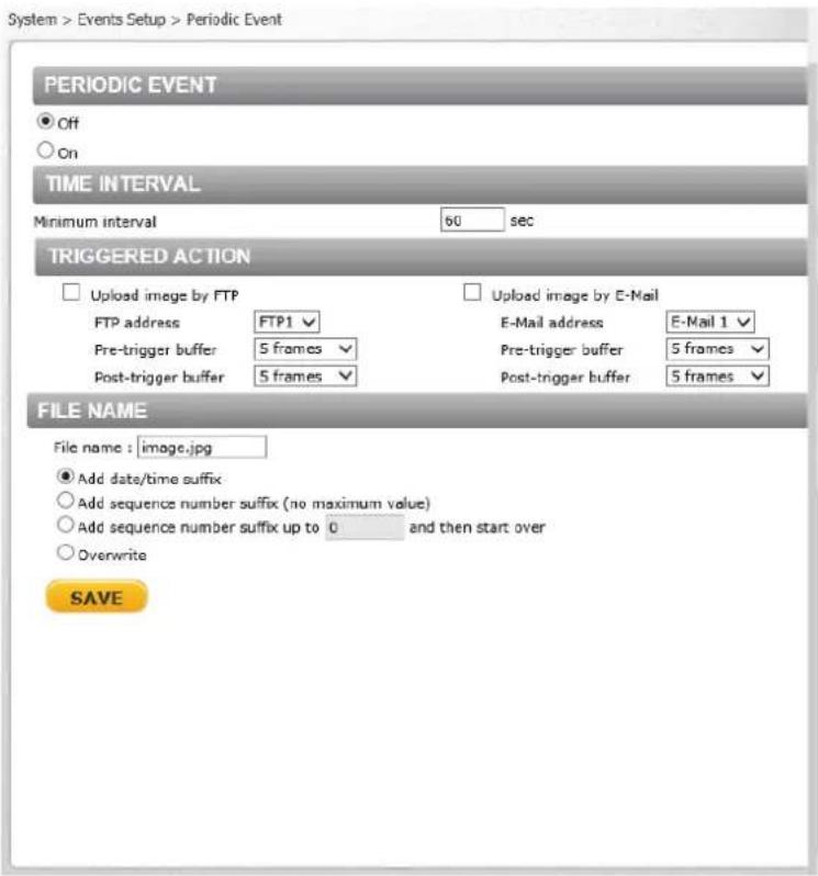
Figure 65: Periodic Event Screen
Periodic Event
Select Off or On to activate this function. The default is Off.
Time Interval
In the Minimum interval text box, enter the number of seconds for the minimum interval between alarms. The range is from 20 to 3600 seconds.
Triggered Action
The Administrator can specify multiple alarm actions to be taken when a triggering event occurs. The options are listed as follows:
- Upload Image by FTP – Selecting this option enables you to assign an FTP site and configure various parameters, as seen in Figure 58: Upload Image by FTP. When the alarm is triggered, event images will be uploaded to the designated FTP site.

Note:
Images can be sent by FTP only when MJPEG is selected as the video stream from the Video Format screen.
- Specify the FTP address to use from the drop-down menu. Select the number of frames for the pre-trigger and post-trigger buffers from the drop-down menu of 1-20 frames.
- Upload Image by E-Mail – Selecting this option enables you to assign an e-mail address and configure various parameters, as shown in Figure 61: Upload Image by E-Mail. When an alarm is triggered, event images will be sent to the designated e-mail address.

Note:
Images can be sent by e-mail only when MJPEG is selected as the video stream from the Video Format screen.
Select one of two e-mail addresses from the drop-down menu. Select the number of frames for the pre-trigger and post-trigger buffers from the drop-down menu of 1-20 frames.

Note:
Make sure SMTP or FTP configuration has been completed. See the Mail and FTP sections for further details.
File Name
- File Name – Enter a file name in the field, for example image.jpg. The uploaded image's file name format is set in this section. Select one that meets your requirements.
- Add date/time suffix (default setting) File name: imageYYMMDD_HHNNSS_XX.jpg Y: Year, M: Month, D: Day H: Hour, N: Minute, S: Second X: Sequence Number
- Add sequence number suffix (no maximum value) File name: imageXXXXXXX.jpg X: Sequence Number
- Add sequence number suffix (limited value) File Name: imageXX.jpg X: Sequence Number
The file name suffix ends at the number being set. For example, if the setting is up to "10," the file name will start from 00, end at 10, and then start over again.
- Overwrite The original image in the FTP site will be overwritten by the new uploaded file with a static filename.
Click SAVE after configuring the settings.
9.3.4.6 Manual Trigger
The Manual Trigger screen is used to specify an alarm to be manually triggered. You can define action to take when an alarm occurs from the System > Events Setup > IO screen.
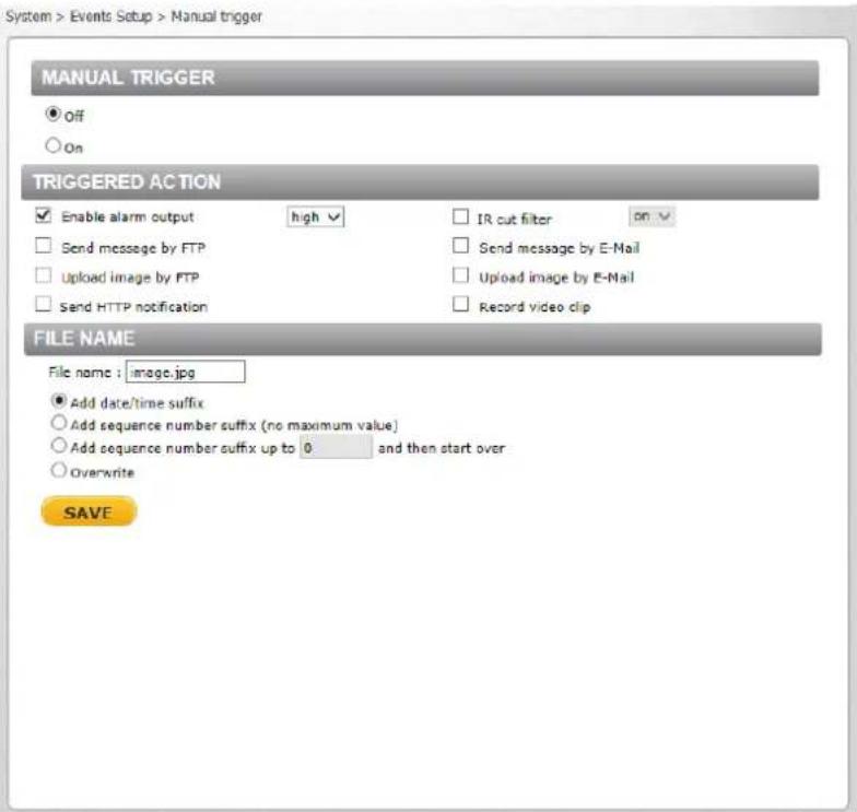
Figure 66: Manual Trigger Screen
Manual Trigger
Select Off or On to activate this function. The default is Off.
Triggered Action
Specify one or both alarms to trigger:
- Enable alarm output – Check this box and select the predefined type of alarm output (high or low) to enable alarm relay when an alarm is triggered.
- Send Message by FTP – The Administrator can select whether to send an alarm message by FTP when an alarm is triggered.
- Upload Image by FTP – Selecting this option enables you to assign an FTP site and configure various parameters, as seen in Figure 58: Upload Image by FTP. When an alarm is triggered, event images will be uploaded to the designated FTP site.

Note:
Images can be sent by FTP only when MJPEG is selected as the video stream from the Video Format screen.
Specify the FTP address to use from the drop-down menu. Select the number of frames for the pre-trigger and post-trigger buffers from the drop-down menu of 1-20 frames.
Check the box for Continue image upload if you wish to use this option. To specify the length of time for the upload, click this radial button and enter the number of seconds. To upload while the trigger is active, click this radial button.
Finally, select the number of frames per second from the drop-down menu next to Image frequency.
- Send HTTP notification – Check this option, select the destination HTTP address, and specify the parameters for HTTP notifications. When an alarm is triggered, the HTTP notifications can be sent to the specified HTTP server. See Figure 59: Send HTTP Notification.
- IR Cut Filter – Select this checkbox to trigger an event when the IR cut filter is activated. From the drop-down menu, select on or off. When the IR Cut filter is set to on, the IR LED illuminator is activated for use in low-light environments in which Night mode is normally used.
- Send message by E-Mail – The Administrator can select whether to send an alarm message by e-mail when an alarm is triggered.
- Upload Image by E-Mail – Selecting this option enables you to assign an e-mail address and configure various parameters, as shown in Figure 61: Upload Image by E-Mail. When an alarm is triggered, event images will be sent to the designated e-mail address.

Note:
Images can be sent by e-mail only when MJPEG is selected as the video stream from the Video Format screen.
Select one of two e-mail addresses from the drop-down menu. Select the number of frames for the pre-trigger and post-trigger buffers from the drop-down menu of 1-20 frames.
Check the box for Continue image upload if you wish to use this option. To specify the length of time for the upload, click this radial button and enter the number of seconds. To upload while the trigger is active, click this radial button. Finally, select the number of frames per second from the drop-down menu next to Image frequency.

Note:
Make sure SMTP or FTP configuration has been completed. See the Mail and FTP sections for further details.
- Record video clip – Select this box in order to save the alarm-triggered recording into a microSDXC card. Enter the number of seconds for the pre-trigger buffer. Select the first radial button to upload for a specified length of time and enter the number of seconds. Alternatively, select the second radial button to upload while the trigger is active. See Figure 60: Record Video Clip.

Note:
To implement function, make sure that local recording with a microSDXC card is activated and that the NAS is properly configured. See Recording for details.
File Name
- File Name – Enter a file name in the field, for example image.jpg. The uploaded image's file name format is set in this section. Select one that meets your requirements.
- Add date/time suffix (default setting) File name: imageYYMMDD_HHNNSS_XX.jpg Y: Year, M: Month, D: Day H: Hour, N: Minute, S: Second X: Sequence Number
- Add sequence number suffix (no maximum value) File name: imageXXXXXXXX.jpg X: Sequence Number
- Add sequence number suffix (limited value) File Name: imageXX.jpg X: Sequence Number
The file name suffix ends at the number being set. For example, if the setting is up to "10," the file name will start from 00, end at 10, and then start over again.
- Overwrite The original image in the FTP site will be overwritten by the new uploaded file with a static filename.
Click SAVE after configuring the settings
From the Edge Recording tab it is possible to configure the following screens:
- SD Card
- Network Share
- Recording
9.3.5.1 SD Card
You can locally record up to 128GB on a Class 10 microSDXC card. The SD Card screen shows the capacity information of the memory card and a recording list of all the recording files saved on the card. You can also format the card and implement automatic recording cleanup on this screen. To implement microSDXC card recording, see Recording.

Figure 67: SD Card Screen

Note:
Format the microSDXC card when using it for the first time. Formatting is also required when a memory card has been used on one camera and is then transferred to a camera that uses a different software platform.
Device Information
Upon inserting the microSDXC card, card information, such as the memory capacity and status, is displayed.
Device Setting
Click Format to format the memory card.
Disk Cleanup Setting
Enable automatic recording cleanup by selecting Enable automatic disk cleanup. From the pull-down menu, specify the minimum length of time over which to remove recordings. For example, remove recordings over 10 days old. Enter the percent of disk capacity used in order to remove the oldest recordings. Click SAVE when finished.
Recording List
Each video file on the microSDXC card is listed in the Recording List table below. The maximum file size is 60 MB per file. See Recording for further details.
When the recording mode in the Recording screen is set as Always (consecutive recording) and the microSDXC card recording is enabled by events triggered, the system immediately saves a recorded event on the memory card once an event occurs. The camera then returns to the regular recording mode after events recording.

Figure 68: Video File Recording List
- Remove – To remove a file, first select the file and then click REMOVE.
- Sort – Click SORT to list the files in the Recording List table in order of name and date.

Note:
The capital letters: R, N, A, (A0), M, (M0) followed by an underscore, appear at the beginning of the file name. They denote the type of recording.
• R - Regular (always or schedule)
• N - Network failure
- M - Motion, (M0 refers to the first motion window trigger)
- A - Alarm (A0 refers to the first alarm trigger input).
- Download – To open/download a video clip, first select the file and then click DOWNLOAD. The selected file window pops up as shown below. Click the AVI file to play the video in the player or download it to a specified location.

Figure 69: Selected File Window
9.3.5.2 Network Share
The Network Share screen shows the capacity information of the Network Attached Storage (NAS) disk and provides a list of all the recording files saved on the disk.

Figure 70: Network Share Screen
You can also format the disk and implement automatic recording cleanup on this screen. To implement NAS recording, see Recording.
Device Information
Upon connecting to the NAS, the following information about the disk is displayed:
• Device type – Displays Network Share
- Free space – Displays the amount of available storage space in GB
- Total size – Displays the total amount of storage space in GB
- Status – Indicates if the camera is online or offline
• Full – Indicates if the disk is full (Yes/No)
- Protocol – Displays the protocol used by the NAS. The default is SAMBA.
Enter the details for the following fields:
- Host – Enter the host IP address
- Share – Enter the path for a shared network storage device
- User name – Enter the name of the user accessing the NAS
- Password – Enter the password of the user accessing the NAS
Storage Tools
Click FORMAT to format the NAS.
Disk Cleanup Setting
Enable automatic recording cleanup by selecting Enable automatic disk cleanup. From the pull-down menu, specify the minimum length of time over which to remove recordings. For example, remove recordings over 10 days old. Enter the percent of disk capacity used in order to remove the oldest recordings. Click SAVE when finished.
Recording List
Each video file stored on the NAS is listed in the Recording list. See Recording for further details. When the recording mode in the Recording screen is set as Always (consecutive recording) and the NAS recording is enabled by events triggered, the system immediately saves a recorded event on the network disk once an event occurs. Then the camera will return to the regular recording mode after events recording.

Figure 71: Video File Recording List
- Remove – To remove a file, first select the file and then click REMOVE.
- Sort – Click SORT to list the files in the Recording list in order of name and date.

Note:
The capital letters: R, N, A, (A0), M, (M0) followed by an underscore, appear at the beginning of the file name. They denote the type of recording.
• R - Regular (always or schedule)
• N - Network failure
• M - Motion, (M0 refers to the first motion window trigger)
• A - Alarm (A0 refers to the first alarm trigger input).
- Download – To open/download a video clip, first select the file and then click DOWNLOAD. The selected file window pops up as shown below. Click the AVI file to play the video in the player or download it to a specified location.

Figure 72: Selected File Window
9.3.5.3 Recording
The Recording screen is used to select a device and to set a schedule for recording clips. Up to 10 schedules can be set.
In the Recording Storage section, select the recording device: SD Card or Network Share.

Note:
It is not recommend to record with the microSD card for 24/7 continuously, as it may not be able to support long term continuous data read/write. Contact the manufacturer of the microSD card for information regarding its reliability and life expectancy.
In the Recording Schedule section, specify the recording schedule. Select one of three options:
- Disable – Disable this function
• Always – Always use this function - Only during time frame – Records only during a specified time frame

Figure 73: Recording Screen
To set the recording schedule
- Select the day.
- Set the start time.
-
Set the duration for recording.
-
Click SAVE to confirm the schedule. The schedule is displayed in the table.

Note:
This option works only if (a) the microSDXC card is installed in the camera or (b) the NAS is configured properly.
9.3.6 Motion Detection
The motion detection function detects suspicious motion and triggers alarms when motion volume in the detected region reaches or exceeds the determined sensitivity threshold value. The Live View pane on the Motion Detection screen is used for creating motion detection regions and indicating motion detection. It is possible to define up to four motion detection regions within the Live View pane. The motion detection function is disabled by default.
![System > Motion Detection Region configuration Edit Motion Detection 1 Off On By schedule Please select ... Motion Indication Bar 0 100 MOTION DETECTION SETTING Sampling pixel interval [1-10] 1 Detection level [1-100] 10 Sensitivity level [1-100] 10 Time interval(sec) [0-7200] 10 TRIGGERED ACTION Enable alarm output high Record video clip Send alarm message by FTP Send alarm message by E-mail Upload image by FTP Upload image by E-Mail Send HTTP notification FILE NAME : image.jpg Add date/time suffix Add sequence number suffix (no maximum value) Add sequence number suffix up to 0 and then start over Overwrite SAVE](/content/2026/05/934891/images/d066b97c233de0ff88076fdf3ded615f260975b99f735fb63a777c7005ead31a.jpg)
Figure 74: Motion Detection Screen
Detected motion is displayed in the Motion Indication Bar. After motion detection has been activated, the bar is divided into 10 segments; each one representing a sensitivity level. Once the motion exceeds the set sensitivity level, the bar turns from green to red.

Note:
If you are using Latitude, it is recommended to set the motion detection from Admin Center.
To activate Motion Detection
From the Motion Detection dropdown list, select a number from 1 to 4.
Do one of the following for each detection region:
Select On for continuous detection.
Select By schedule for scheduled detection. For instructions how to set a schedule for motion detection, refer to Schedule.
Create a Motion Detection region. See instructions below.
Paint the Motion Detection region. See instructions below.
Configure the Motion Detection settings. See instructions below.
Set triggered actions. See instructions below.
To create a Motion Detection region
Click Edit. The Region Configuration editing options are displayed.

Figure 75: Region Configuration Options
Click Add. A motion detection region is created on-screen.
To change the size of the region, drag an edge of the box to the desired cell.
Click SAVE.
To paint a motion detection region
Check Region paint.
To set the number of cells to paint, from the brush drop-down list, select 1x1, 3x3, or 5x5.
Click SAVE.
To set a schedule
Select By schedule. The message "Please Select" is displayed.
Click Please select. A drop-down menu opens.
From the drop-down menu, select a schedule from 1 to 10. The selected schedules are displayed in a horizontal field above the drop-down menu.
Click SAVE.
To configure motion detection settings
Sampling pixel interval [1-10] – Select a number from 1-10. The default value is 1. If the value is set as 3, within the detection region, the system will take one sampling pixel for every 3 pixels by each row and each column (see the figure below).
natural_image
Checkerboard pattern with alternating red and white squares (no text or symbols)Figure 76: Pixel Interval Illustration
Detection level [1-100] – Select a number from 1-100. The default level is 40. This sets detection level for each sampling pixel; the smaller the value, the more sensitive it is.
Sensitivity level [1-100] – Select a number from 1-100. The default level is 60, which means if 40% or more sampling pixels are detected differently, the system will detect motion. The bigger the value, the more sensitive it is and more colored segments will be displayed in the Motion Indication Bar.
Time interval (sec) [0-7200] – Select a number from 0-7200 (seconds). The default interval is 10. The value is the interval between each detected motion.
Set Triggered Actions
The Administrator can specify alarm actions to be taken when motion is detected. See Figure 74: Motion Detection Screen. The options are listed as follows:
- Enable alarm output – Check this box and select the predefined type of alarm output (low or high) to enable alarm relay when tampering is detected.
- Record video clip – Select this box to store the motion detection alarm recording in a microSDXC card or on the NAS when tampering is detected. Enter the number of seconds for the pre-trigger buffer. Select the first radial button to upload for a specified length of time and enter the number of seconds. Alternatively, select the second radial button to upload while the trigger is active.

Note:
Make sure the local recording (with microSDXC card) is activated so that this function can be implemented. See Recording for further details.
- Send alarm message by FTP – Select whether to send an alarm message by FTP when motion is detected.
- Upload image by FTP – Select this box in order to upload an image to a designated FTP site when motion is detected according to various parameters, as seen in Figure 58: Upload Image by FTP.

Note:
Images can be sent by FTP only when MJPEG is selected as the video stream from the Video Format screen.
Specify the FTP address to use from the drop-down menu. Select the number of frames for the pre-trigger and post-trigger buffers from the drop-down menu of 1-20 frames.
Check the box for Continue image upload if you wish to use this option. To specify the length of time for the upload, click this radial button and enter the number of seconds. To upload while the trigger is active, click this radial button. Finally, select the number of frames per second from the drop-down menu next to Image frequency.
- Send HTTP notification – Check this box to send a notification by HTTP. Select the destination HTTP address from the drop-down menu and specify the parameters for event notifications by motion detection triggered. When an alarm is triggered, the notification will be sent to one of two specified HTTP servers. See Figure 59: Send HTTP Notification.
- Send alarm message by E-Mail – Select whether to send an alarm message by e-mail when motion is detected.

Note:
Make sure that local recording (with a microSDXC card) is activated so that this function can be implemented. See Recording for further details.
- Upload image by E-Mail – Select this box in order to assign an e-mail address and configure various parameters, as seen in Figure 61: Upload Image by E-Mail.

Note:
Images can be sent by e-mail only when MJPEG is selected as the video stream from the Video Format screen.
When motion is detected, event images are sent to one of two designated e-mail addresses. Select the number of frames for the pre-trigger and post-trigger buffers from the drop-down menu of 1-20 frames.
Check the box for Continue image upload to use this option. To specify the length of time for the upload, click this radial button and enter the number of seconds. To upload while the trigger is active, click this radial button. Finally, select the number of frames per second from the dropdown menu next to Image frequency.

Note:
Make sure that SMTP or FTP configuration has been completed. See the Mail and FTP sections for further details.
File Name
The uploaded image's filename format is set in this section. Select one that meets your requirements. Click SAVE to save the motion detection settings.
9.3.7 Schedule
The Schedule screen is used for setting schedules for the network failure detection, tampering and motion detection functions. The functions in this tab allow administrators to create customized schedules for the camera that uses this option. If a schedule exists, the administrator can apply that schedule to this camera using the available drop-down list. See Figure 77: Schedule Screen.
To access the schedule function, open the Main window, select the System tab, and click the Schedule tab.

Note:
This application is not the same as the Recording Schedule function. It is not used for recording live video.

Figure 77: Schedule Screen
To create a new schedule or edit an existing schedule
- Select the appropriate checkbox for the day(s) of the week (Sun, Mon, Tue, Wed, Thu, Fri and Sat) to create a schedule.
- Set Start time (for example, 09:00) and Duration (for example, 4:00 hours).
- Click SAVE to apply the newly created schedule to the camera.
To remove a schedule
- To remove a schedule, select the setup data line by line.
- Click DELETE to remove.
9.3.8 File Location
From the File Location screen, specify a storage location for snapshots and web recordings. The default setting is: C:. After confirming the setting, click SAVE to save the snapshots and recordings in the designated location.

Figure 78: File Location Screen

Note:
- Make sure the selected file path contains valid characters.
- When using Windows 8 OS, the storage location cannot be C:. You must define a storage location that does not require Administrator privileges on the PC.
9.3.9 Maintenance
Clicking the Maintenance tab in the System screen opens a drop-down menu with the following tabs:
- Log File
• User Information
• Factory Default
- Software Version
• Software Upgrade
- Parameters
9.3.9.1 Log File
Click Log file to view the system log file. The content of the file provides information about connections after system boot-up.
![[Fri Apr 2 22:17:00 2010] --Network interface initialized start [Fri Apr 2 22:17:07 2010] --Network interface initialized end [Fri Apr 2 22:17:07 2010] --Host IP = 172.19.7.71 [Fri Apr 2 22:17:07 2010] --Subnet Mask = 255.255.255.0 [Fri Apr 2 22:17:07 2010] --Gateway = 172.19.7.2 [Fri Apr 2 22:17:07 2010] --MAC address = 00:1B:D8:80:35:D8 [Fri Apr 2 22:17:27 2010] --Admin@::ffff:172.20.12.104 GET / HTTP/1.1 [Fri Apr 2 22:17:27 2010] --Admin@::ffff:172.20.12.104 GET /cgi-bin/setlogout.cgi H [Fri Apr 2 22:17:30 2010] --Admin@::ffff:172.20.12.104 GET /cgi-bin/mainhtml.cgi H [Fri Apr 2 22:17:31 2010] --Admin@::ffff:172.20.12.104 GET /cgi-bin/center.cgi HTTP [Fri Apr 2 22:17:34 2010] --Admin@::ffff:172.20.12.104 GET /cgi-bin/showdate.cgi H [Sat Apr 3 02:59:27 2010] --Admin@::ffff:172.19.7.95 GET /cgi-bin/admin/param.cgi [Sat Apr 3 02:59:27 2010] --Admin@::ffff:172.19.7.95 GET /cgi-bin/admin/param.cgi [Sat Apr 3 03:00:01 2010] --Admin@::ffff:172.19.7.95 GET /cgi-bin/admin/param.cgi [Sat Apr 3 03:00:01 2010] --Admin@::ffff:172.19.7.95 GET /cgi-bin/admin/param.cgi [Sat Apr 3 03:45:27 2010] --Admin@::ffff:172.19.7.95 GET /cgi-bin/admin/param.cgi [Sat Apr 3 03:45:27 2010] --Admin@::ffff:172.19.7.95 GET /cgi-bin/admin/param.cgi [Sat Apr 3 05:14:16 2010] --Admin@::ffff:172.19.7.80 GET /cgi-bin/admin/param.cgi [Sat Apr 3 05:14:16 2010] --Admin@::ffff:172.19.7.80 GET /cgi-bin/admin/param.cgi [Sat Apr 3 06:06:15 2010] --Admin@::ffff:172.19.7.80 GET /cgi-bin/admin/param.cgi [Sat Apr 3 06:06:15 2010] --Admin@::ffff:172.19.7.80 GET /cgi-bin/admin/param.cgi [Sat Apr 3 23:21:23 2010] --Admin@::ffff:172.19.7.80 GET / HTTP/1.1 [Sat Apr 3 23:21:23 2010] --Admin@::ffff:172.19.7.80 GET /cgi-bin/setlogout.cgi HT [Sat Apr 3 23:21:23 2010] --Admin@::ffff:172.19.7.80 GET /cgi-bin/mainhtml.cgi HT](/content/2026/05/934891/images/bd877b746332d88977da13fbfee0250159dbd9b7e4bd2ac30a1a12b3a313bf30.jpg)
Figure 79: Log File Screen
9.3.9.2 User Information
The Administrator can view each user's login information and privileges in the User information screen shown below.
View User Login Information
Click GET USER INFORMATION to see each user's details. For example: Admin: 1234. This indicates that the user's login username is Admin and the password is 1234.

Figure 80: User Information Screen – Get User Information
View User Privilege
Click GET USER PRIVACY to view each user's privileges.

Figure 81: User Information – Get User Privacy
In the screen above, both Admin and User are granted privileges of I/O access, Camera control, Talk and Listen, which are the maximum privileges that can be granted.

Note:
User credentials and privileges are set in the User screen (page 41).
9.3.9.3 Factory Default
The Factory Default screen is shown below. Follow the instructions to reset the camera to factory default settings if needed.

Figure 82: Factory Default Screen
Full Restore
Click FULL RESTORE to restore the factory default settings. The system restarts in 30 seconds.

Note:
The IP address and all other settings will be restored to factory default settings.
Partial Restore
Click PARTIAL RESTORE to restore the factory default settings, but save the network settings. The system restarts in 30 seconds.

Figure 83: Partial Restore Screen
Reboot
Click REBOOT to restart the system without changing current settings.
9.3.9.4 Software Version
The current version of the software is displayed in the Software Version screen.

Figure 84: Software Version Screen
9.3.9.5 Software Upgrade
The Software Upgrade screen enables you to select a software file to upload.

Figure 85: Software Upgrade Screen

Note:
- Make sure that the software upgrade file is available before performing a software upgrade.
- Do not change the file name. If you change the upgrade file name, the system will fail to find the file.

Warning:
- Do not unplug power while entering file names.
- Do not unplug power or change the screen while upgrading software.
Avertissement:
To upgrade the software
- In the Step 1 text box, click Browse and select the binary file to be uploaded, for example, uImage+userland.img.

Note:
Do not change the file name. If you change the upgrade file name, the system will fail to find the file.
-
From the drop-down menu of binary files in Step 2, select the file to upgrade. In the above example uImage+userland.img is selected.
-
Click UPGRADE. The system verifies that the upgrade file exists and begins to upload the file. The upgrade status bar is displayed on the screen. When the upgrade process is completed, the Live screen is displayed.
- Close the web browser.
From the Windows Start menu, select Control Panel.
Select Uninstall a Program.
In the Currently installed programs list, select Quasar Player.
Click Uninstall to delete the existing DVPlayer or DCViewer plug-in file.

Note:
For more information about deleting an existing web player, see Installing and Deleting the Web Player (page 138).
Install the new ActiveX plug-in.
9.3.9.6 Parameters
The Parameters screen displays all of the system's parameter settings.
![QuasarQHD IP Camera Initial Configuration File ====================[Camera setting] ====================exposure mode = max shutter gain = <3> min shutter speed = <4> fixed shutter speed = <200> fixed gain value = <0> white balance mode = white balance rgain = <57> white balance bgain = <54> brightness value = <128> sharpness value = <4>](/content/2026/05/934891/images/6c2b4ac4cd75eb24c7714733ffed4dc720600aaf3d4f8321537783f8f4967498.jpg)
Figure 86: Parameter Screen

Note:
Slide the sidebar located on the right of the screen to view the entire list of parameters.
From the Import/Export screen you can export configuration files to a specified location and retrieve data by uploading an existing configuration file to the camera.
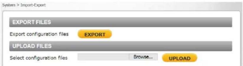
Figure 87: Import/Export Screen
To export a configuration file
- Click EXPORT. An information bar opens.

Figure 88: File Download Screen
- Click Save.
- Specify a location to save the configuration file.
To import a configuration file
- Click Browse to select the configuration file
- Click UPLOAD. The file is uploaded to the camera.

Select the Streaming tab in the navigation bar at the top of the screen to display the configurable video and audio selections in the sidebar. From the Streaming sidebar, the Administrator can configure a specific video resolution, video compression mode, video protocol, audio transmission mode, etc.

Figure 89: Streaming Section Tabs
Details of these settings are specified in the following sections:
- Video Format
• Video Compression
• Video ROI Encoding
• Video OCX Protocol
- Video Frame Rate
- Video Mask
- Audio
9.4.1 Video Format
From the Video Format screen, you can configure the following settings:
• Video Resolution Settings
• CM-6204 Video Resolution Settings
• CM-6208 Video Resolution Settings
• Text Overlay Settings
• Video Rotate Type
• GOV Settings
• H.264 Profile

Note:
After changing the video format settings, you must restart the camera and re-enter the unit's IP address again in your browser in order to use the unit with the new settings.
CM-6204 cameras support three video streams.

Figure 90: CM-6204 Video Format Screen
CM-6208 cameras support four video streams.

Figure 91: CM-6208 Video Format Screen
CM-6204 Video Resolution Settings
The following video resolutions are supported:
• H.264-Only
- MJPEG-Only
• H.264 + H.264 and H.264 + MJPEG
H.264 + H.264 + H.264 and H.264 + H.264 + MJPEG

Note:
Images can be sent by FTP or email only when MJPEG steaming is selected as one of the streams.
H.264-Only
| H.264-Only | |
| Stream 1 | BNC Support |
| 2560 x 1440 (25/30 fps) | Y |
| 1920 x 1080 (25/30 fps) | Y |
| 1280 x 720 (25/30 fps) | Y |
| 720 x 576 (25 fps)720 x 480 (30 fps) | Y |
MJPEG-Only
| MJPEG-Only | |
| Stream 1 | BNC Support |
| 1920 x 1080 (25/30 fps) | Y |
| 1280 x 720 (25/30 fps) | Y |
| 720 x 576 (25 fps)720 x 480 (30 fps) | Y |
H.264 + H.264 and H.264 + MJPEG
| H.264 + H.264/MJPEG | |
| Stream 1 | Stream 2 |
| 2560 x 1440 (12/15 fps) | 1920 x 1080 (1215/ fps) |
| 1280 x 720 (12/15 fps) | |
| 2560 x 1440 (25/30 fps) | 2560 x 1440 (6/6 fps) |
| 720 x 576 (25 fps)720 x 480 (30 fps) | |
| 1920 x 1080 (25/30 fps) | 1920 x 1080 (25/30 fps) |
| 1280 x 720 (25/30 fps) | |
| 1280 x 720 (25/30 fps) | 1280 x 720 (25/30 fps) |
| 720 x 576 (25 fps)720 x 480 (30 fps) | |
| 720 x 576 (25 fps)720 x 480 (30 fps) | 720 x 576 (25 fps)720 x 480 (30 fps) |
H.264 + H.264 + H.264 and H.264 + H.264 + MJPEG
| H.264 + H.264 + H.264/MJPEG | ||
| Stream 1 | Stream 2 | Stream 3 |
| 2560 x 1440 (12/15 fps) | 1920 x 1080 (12/15 fps) | 720 x 576 (12 fps)720 x 480 (15 fps) |
| 1280 x 720 (12/15 fps) | ||
| 720 x 576 (12 fps)720 x 480 (15 fps) | ||
| 1920 x 1080 (25/30 fps) | 1280 x 720 (25/30 fps) | 720 x 576 (25 fps)720 x 480 (30 fps) |
| 720 x 576 (25 fps)720 x 480 (30 fps) | ||
| 1280 x 720 (25/30 fps) | 1280 x 720 (25/30 fps) | 1280 x 720 (25/30 fps) |
| 720 x 576 (25 fps)720 x 480 (30 fps) | ||
| 720 x 576 (25 fps)720 x 480 (30 fps) | 720 x 576 (25 fps)720 x 480 (30 fps) | |
| 720 x 576 (25 fps)720 x 480 (30 fps) | 720 x 576 (25 fps)720 x 480 (30 fps) | 720 x 576 (25 fps)720 x 480 (30 fps) |
CM-6208 Video Resolution Settings
The following video resolutions are supported:
• H.264-Only
- MJPEG-Only
H.264 + H.264
H.264 + MJPEG
• H.264 + H.264 + H.264 and H.264 + H.264 + MJPEG
• H.264 + H.264 + H.264 + H.264 and H.264 + H.264 + H.264 + MJPEG

Note:
Images can be sent by FTP or email only when MJPEG steaming is selected as one of the streams.
H.264-Only
| H.264-Only | ||
| PAL | NTSC | BNC Support |
| 3840 x 2160 (25 fps) | 3840 x 2160 (30 fps) | Y |
| 3840 x 2160 (24 fps) | 3840 x 2160 (24 fps) | Y |
| 1920 x 1080 (25 fps) | 1920 x 1080 (30 fps) | Y |
| 1280 x 720 (25 fps) | 1280 x 720 (30 fps) | Y |
| 720 x 576 (25 fps) | 720 x 480 (30 fps) | Y |
MJPEG-Only
| MJPEG-Only | ||
| PAL | NTSC | BNC Support |
| 1920 x 1080 (25 fps) | 1920 x 1080 (30 fps) | Y |
| 1280 x 720 (25 fps) | 1280 x 720 (30 fps) | Y |
| 720 x 576 (25 fps) | 720 x 480 (30 fps) | Y |
H.264 + H.264 and H.264 + MJPEG
| H.264 + H.264/MJPEG (PAL) | ||
| Stream 1 | Stream 2 | BNC Support |
| 3840 x 2160 (12 fps) | 1920 x 1080 (12 fps) | NA |
| 3840 x 2160 (20 fps) | 1280 x 720 (20 fps) | NA |
| 3840 x 2160 (25 fps) | 720 x 576 (25 fps) | Y |
| 1920 x 1080 (25 fps) | 1920 x 1080 (25 fps) | NA |
| 1280 x 720 (25 fps) | NA | |
| 720 x 576 (25 fps) | Y | |
| 1280 x 720 (25 fps) | 1280 x 720 (25 fps) | NA |
| 720 x 576 (25 fps) | Y | |
| 720 x 576 (25 fps) | 720 x 576 (25 fps) | Y |
| H.264 + H.264/MJPEG (NTSC) | ||
| Stream 1 | Stream 2 | BNC Support |
| 3840 x 2160 (15 fps) | 1920 x 1080 (15 fps) | NA |
| 3840 x 2160 (20 fps) | 1280 x 720 (20 fps) | NA |
| 3840 x 2160 (25 fps) | 720 x 480 (25 fps) | Y |
| 1920 x 1080 (30 fps) | 1920 x 1080 (30 fps) | NA |
| 1280 x 720 (30 fps) | NA | |
| 720 x 480 (30 fps) | Y | |
| 1280 x 720 (30 fps) | 1280 x 720 (30 fps) | NA |
| 720 x 480 (30 fps) | Y | |
| 720 x 480 (30 fps) | 720 x 480 (30 fps) | Y |
H.264 + H.264 + H.264 and H.264 + H.264 + MJPEG
| H.264 + H.264 + H.264/MJPEG (PAL) | ||
| Stream 1 | Stream 2 | Stream 3 |
| 3840 x 2160 (12 fps) | 1920 x 1080 (12 fps) | 720 x 576 (12 fps) |
| 1920 x 1080 (25 fps) | 1280 x 720 (25 fps) | 1280 x 720 (25 fps) |
| 720 x 576 (25 fps) | 720 x 576 (25 fps) | |
| 1280 x 720 (25 fps) | 1280 x 720 (25 fps) | 1280 x 720 (25 fps) |
| 720 x 576 (25 fps) | 720 x 576 (25 fps) | |
| 720 x 576 (25 fps) | 720 x 576 (25 fps) | 720 x 576 (25 fps) |
| H.264 + H.264 + H.264/MJPEG (NTSC) | ||
| Stream 1 | Stream 2 | Stream 3 |
| 3840 x 2160 (15 fps) | 1920 x 1080 (15 fps) | 720 x 480 (15 fps) |
| 1920 x 1080 (30 fps) | 1280 x 720 (30 fps) | 1280 x 720 (30 fps) |
| 720 x 480 (30 fps) | ||
| 720 x 480 (30 fps) | 720 x 480 (30 fps) | |
| 1280 x 720 (30 fps) | 1280 x 720 (30 fps) | 1280 x 720 (30 fps) |
| 720 x 480 (30 fps) | ||
| 720 x 480 (30 fps) | 720 x 480 (30 fps) | |
| 720 x 480 (30 fps) | 720 x 480 (30 fps) | 720 x 480 (30 fps) |
H.264 + H.264 + H.264 + H.264 and H.264 + H.264 + H.264 + MJPEG
| H.264 + H.264 + H.264 + H.264/MJPEG (PAL) | |||
| Stream 1 | Stream 2 | Stream 3 | Stream 4 |
| 3840 x 2160 (12 fps) | 1920 x 1080 (12 fps) | 1280 x 720 (12 fps) | 720 x 576 (12 fps) |
| 720 x 576 (12 fps) | |||
| 1280 x 720 (12 fps) | 1280 x 720 (12 fps) | ||
| 720 x 576 (12 fps) | |||
| 720 x 576 (12 fps) | 720 x 576 (12 fps) | ||
| 1920 x 1080 (25 fps) | 1920 x 1080 (25 fps) | 1280 x 720 (25 fps) | 720 x 576 (25 fps) |
| 720 x 576 (25 fps) | |||
| 1280 x 720 (25 fps) | 1280 x 720 (25 fps) | ||
| 720 x 576 (25 fps) | |||
| 720 x 576 (25 fps) | 720 x 576 (25 fps) | ||
| 1280 x 720 (25 fps) | 1280 x 720 (25 fps) | 1280 x 720 (25 fps) | |
| 720 x 576 (25 fps) | |||
| 720 x 576 (25 fps) | 720 x 576 (25 fps) | ||
| 720 x 576 (25 fps) | 720 x 576 (25 fps) | 720 x 576 (25 fps) | |
| H.264 + H.264 + H.264 + H.264/MJPEG (NTSC) | |||
| Stream 1 | Stream 2 | Stream 3 | Stream 4 |
| 3840 x 2160 (15 fps) | 1920 x 1080 (15 fps) | 1280 x 720 (15 fps) | 720 x 480 (15 fps) |
| 720 x 480 (15 fps) | |||
| 1280 x 720 (15 fps) | 1280 x 720 (15 fps) | ||
| 720 x 480 (15 fps) | |||
| 720 x 480 (15 fps) | 720 x 480 (15 fps) | ||
| 1920 x 1080 (30 fps) | 1920 x 1080 (30 fps) | 1280 x 720 (30 fps) | 720 x 480 (30 fps) |
| 720 x 480 (30 fps) | |||
| 1280 x 720 (30 fps) | 1280 x 720 (30 fps) | ||
| 720 x 480 (30 fps) | |||
| 720 x 480 (30 fps) | 720 x 480 (30 fps) | ||
| 1280 x 720 (30 fps) | 1280 x 720 (30 fps) | 1280 x 720 (30 fps) | |
| 720 x 480 (30 fps) | |||
| 720 x 480 (30 fps) | 720 x 480 (30 fps) | ||
| 720 x 480 (30 fps) | 720 x 480 (30 fps) | 720 x 480 (30 fps) | |

Note:
Latitude does not accept settings above 25 fps when operating on a PAL system or above 30 fps when operating in an NTSC system.
Text Overlay Settings
Select the relevant checkbox for the data to include in the on-screen display:
- Include date
- Include time
- Include text string – When this checkbox is selected, enter the string in the text box that opens.
- Include subtitle – When this checkbox is selected, enter the string in the text box that opens.
Video Rotate Type
You can change video display type if necessary. Selectable video rotate types include Normal video, Flip video, Mirror video, 90 degree clockwise, 180 degree rotate, and 90 degree counterclockwise (referred to as "90 and 270 degrees" in Latitude). Differences among these types are illustrated below. Suppose the displayed image of the camera is shown as follows.

Figure 92: View-1 (Source)
To rotate the image vertically, for example, select Flip video. The displayed image is reversed as shown below.
Figure 93: View-2 Image Rotated Vertically (Reversed)
Following are descriptions of different video rotate types.
- Normal video – The image appears as it is viewed. This is the default setting.
- Flip video – The image is reversed along its horizontal axis.
- Mirror video – The image is reversed along its vertical axis.
- 90 degree clockwise – The image rotates 90irc clockwise (to the right) and is displayed in 9:16 aspect ratio. This mode is ideal for use when monitoring a long, narrow area, such as an aisle, hallway or corridor.
- 180 degree rotate – The image rotates 180irc counter-clockwise (to the left).
- 90 degree counterclockwise – The image rotates 90irc counter-clockwise (to the left) and is displayed in 9:16 aspect ratio. This mode is recommended when monitoring a long, narrow area, such as an aisle, hallway or corridor. This mode is referred to in Latitude as “90 and 270 degrees” mode.
Click SAVE to confirm the setting.

Note:
Image rotation is not supported for 4K streams above 15 fps.
GOV Settings
Users can set the GOV length to determine the frame structure (I-frames and P-frames) in a video stream for saving bandwidth. The setting range is from 1 to 255. A longer GOV means decreasing the frequency of I-frames. The default GOV setting for H.264-1 and H.264-2 is 50/60 (PAL/NTSC). The default GOV setting for H.264-3 and H.264-4 (CM-6208 only) is 25/30 (PAL/NTSC). Click SAVE to confirm the GOV setting.
H.264 Profile
The H.264 standard defines 21 sets of capabilities. These are referred to as profiles and they target specific classes of applications. In the security industry, the most common are as follows:
• Baseline Profile (BP)
Primarily for low-cost applications that require additional data loss robustness, Baseline Profile is used in some videoconferencing and mobile applications. This is the most common profile used in IP security cameras due to the low computational cost of processing the video using this profile.
- Main Profile (MP)
This profile provides improved picture quality at reduced bandwidths and storage costs and is becoming more common as the camera processors (DSPs) become more able to handle the processing load. Main Profile can save 10-12% over Baseline. This is the default profile.
• High Profile (HP)
High Profile is the primary profile for HD broadcast applications. It can save 10-12% of the storage cost over Main Profile. However, it may also increase video latency, depending on the stream structure. Units default to the Main Profile to provide the best trade-off between storage size and video latency.
Click SAVE to confirm the settings.
9.4.2 Video Compression
From the Video Compression screen, you can specify MJPEG and H.264 compression settings. CM-6204 cameras support three video streams.
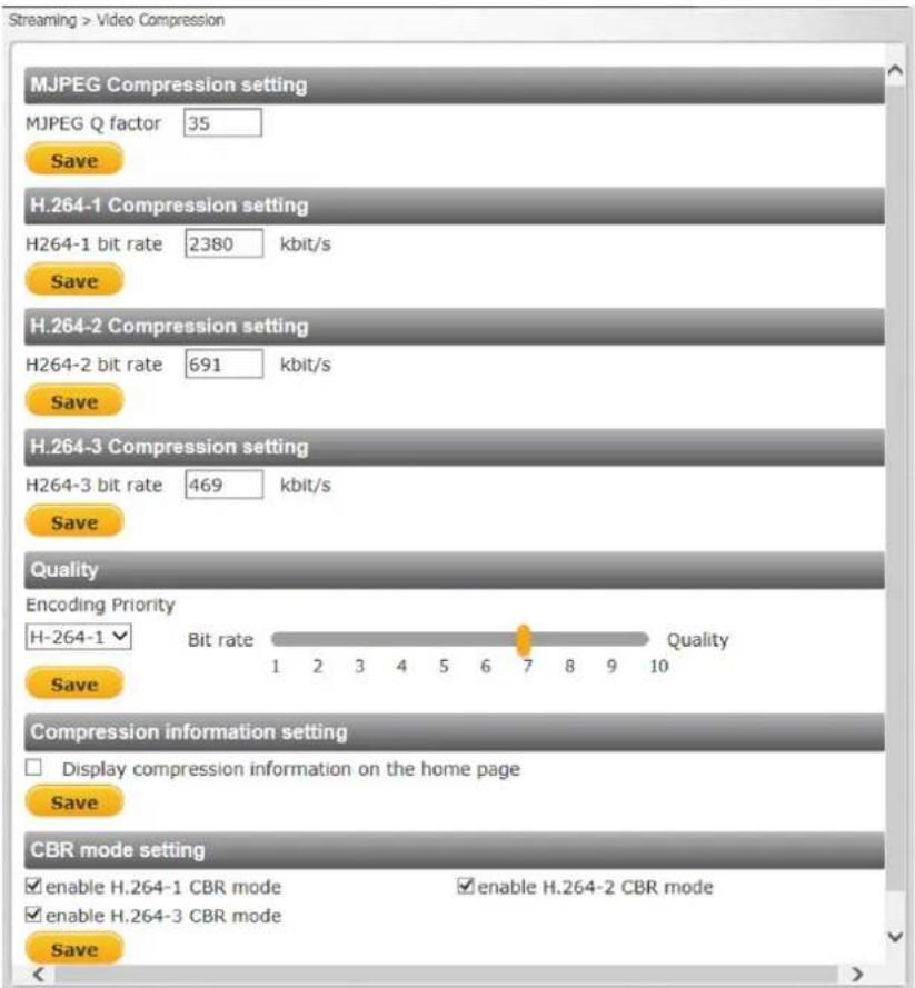
Figure 94: Video Compression Screen-CM-6204
CM-6208 cameras support four video streams.
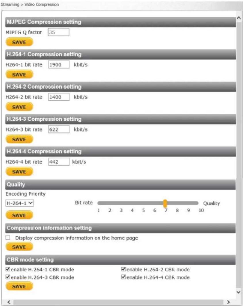
Figure 95: Video Compression Screen-CM-6208
MJPEG Compression Setting
A higher value implies higher bit rates and higher visual quality. The default setting of the MJPEG Q factor is 35. The setting range is from 1 to 70. Click SAVE to confirm the setting.
H.264 Compression Setting
The default setting of H.264-1 is 4096. The default setting for the other streams is 1024 kbps. Each stream can be configured individually. The setting range is from 64 to 20,480 kbps. Click SAVE to confirm the setting.

Note:
A total of 26,624 kbps is available on the camera for streaming. A single stream is limited to 20,480 kbps.
Quality
The Encoding Priority function enables the user to adjust the quality of the picture along a single axis. The slider is configured according to Quantization Parameter (QP) values. Setting QP to a high value increases the bit rate and results in high compression, but this is at the expense of poor decoded image quality. Setting QP to a low value results in better decoded image quality, but with lower compression.
Encoding Priority should be set for each H.264 stream. The slider ranges from 1 (low bit rate) to 10 (high picture quality). The default setting is 7. Click SAVE to confirm the setting.

Note:
The Encoding Priority setting can be used only when H.264 is selected.
Compression Information Setting
Select the checkbox to display compression information on the Home page. The default setting is Display compression information in the home page. Click SAVE to confirm the setting.
CBR Mode Setting
If available bandwidth is limited, select CBR (Constant Bit Rate) mode. To operate the camera in Variable Bit Rate (VBR) mode, uncheck the CBR checkbox. Click SAVE to confirm the setting.

Note:
CBR mode affects image quality.
9.4.3 Video ROI Encoding
It is possible to configure Region of Interest settings for three (CM-6204) or four (CM-6208) H.264 streams on the Video ROI Encoding screen. The image displayed within the ROI box can be displayed with a higher bit rate and quality than the image outside of the box. Overall bit rate is not affected by selecting Regions of Interest. Enhancing the video where the quality is very important consumes more bandwidth, but enables lowering image quality and bandwidth consumption on less important zones in the scene.

Figure 96: Video ROI Encoding Screen
To use ROI encoding
- From the Video Stream drop-down menu, select the H.264 stream. Three streams are available on CM-6204 cameras. Four streams are available on CM-6208 cameras.
- From the ROI Encoding drop-down menu, select Enable to activate this function.
- From the Quality drop-down menu, select a number between -15 (lowest image quality) to +15 (highest image quality) or default (where the image quality of the video in the box is the same as the image quality outside the box).
- Click SAVE when finished.
- Drag the box in the ROI Encoding Window to cover the zone for which you want to activate ROI encoding.
- Click ADD to create a new zone or DELETE to remove a zone.
- Click SAVE when finished.
9.4.4 Video OCX Protocol
From the Video OCX Protocol screen, you can select various protocols for streaming media over the network. In the case of multicast networking, select Multicast mode. Three streams are available on CM-6204 cameras. Four streams are available on CM-6208 cameras.
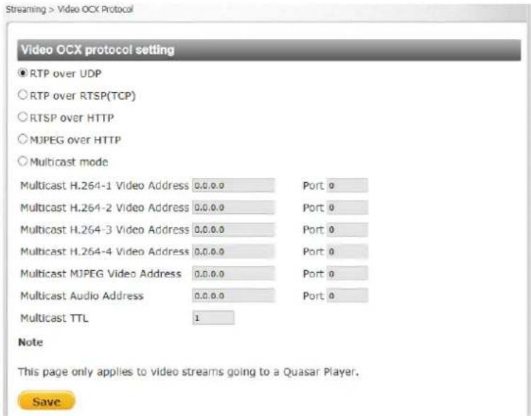
Figure 97: Video OCX Protocol Screen
Video OCX protocol setting options include:
- RTP over UDP
• RTP over RTSP (TCP) - RTSP over HTTP
- MJPEG over HTTP
- Multicast mode – Enter in each field all required data, including Multicast H.264-1 Video Address, Multicast H.264-2 Video Address, Multicast H.264-3 Video Address, Multicast H.264-4 Video Address (CM-6208 only), Multicast MJPEG Video Address, Multicast Audio Address, and Multicast TTL.
Click SAVE to confirm the settings.
9.4.5 Video Frame Rate
From the Video Frame Rate screen, you can specify the frames per second (fps) for each video compression format. CM-6204 includes three streams. CM-6208 includes four streams.

Figure 98: Video Frame Rate Screen
MJPEG/H.264 Frame Rate Setting
When operating the unit in H.264-only mode, the default frame is 30 fps in NTSC and 25 fps in PAL.

Note:
A lower frame rate decreases video smoothness.
The following settings apply when the unit is operated in any mode other than H.264-only:
- MJPEG – The setting range of the MJPEG Frame Rate is from 1 to 30 in NTSC and 1 to 25 in PAL. The default setting is 30 fps in NTSC and 25 fps in PAL.
- H.264-1 – The setting range for the H-264-1 Frame Rate is from 1 to 15 in NTSC and 1 to 12 in PAL. The default setting is 15 fps in NTSC and 12 fps in PAL.
- H.264-2 – The setting range for the H-264-2 Frame Rate is from 1 to 15 in NTSC and 1 to 12 in PAL. The default setting is 15 fps in NTSC and 12 fps in PAL.
- H.264-3 – When using four streams on the CM-6208, the setting range for the H-264-3 Frame Rate is from 1 to 15 in NTSC and 1 to 12 in PAL. The default setting is 15 fps in NTSC and 12 fps in PAL. When using three streams, the setting range for the H-264-3 Frame Rate is from 1 to 30 in NTSC and 1 to 25 in PAL.
- H.264-4 (CM-6208 only) – The setting range for the H-264-4 Frame Rate is from 1 to 15 in NTSC and 1 to 15 in PAL. The default setting is 15 fps in NTSC and 12 fps in PAL.
Click SAVE to confirm the settings.

Note:
Images can be sent by FTP or email only when MJPEG steaming is selected as one of the streams.
9.4.6 Video Mask
From the Mask screen, you may select up to five rectangular portions of the View Area to 'Mask.' Below is an illustration with one mask displayed in the View Area.

Figure 99: Mask Screen
Active Mask Function
When a Video [Privacy] Mask is turned on, the area within the mask or box is blocked out or obscured from view.
To enable a mask
- Check a Video Mask checkbox. A red frame is displayed in the Live Video pane on the right side.
- Use the mouse to drag and drop, adjust the mask's size, and place it on the target zone.

Note:
It is suggested to set the Video Mask twice as large as the object it covers.
To disable a mask
- Uncheck the checkbox of the Video Mask meant to be deleted. The selected mask disappears from the Live Video pane.
Mask Setting
- Mask color – The selections of Mask color include red, black, white, yellow, green, blue, cyan, and magenta.
Click SAVE to confirm the setting.
9.4.7 Audio
From the Audio screen you can select the Transmission Mode, Server Gain, Bit Rate, and enable or disable storage of the audio recording.
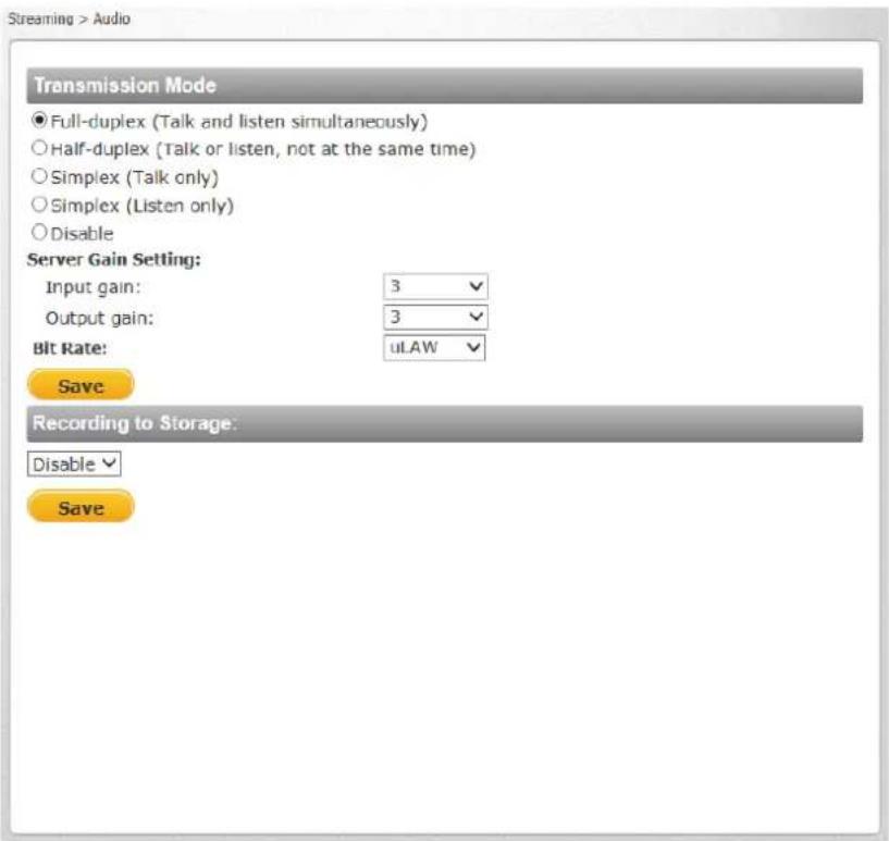
Figure 100: Audio Screen
Transmission Mode
- Full-duplex (Talk and listen simultaneously) – In the Full-duplex mode, the local and remote sites can communicate with each other simultaneously, i.e. both sites can speak and be heard at the same time.
- Half-duplex (Talk or listen, not at the same time) – In the Half-duplex mode, the local or remote site can only talk or listen to the other site at one time.
- Simplex (Talk only) – In the Talk only Simplex mode, the local/remote site can only talk to the other site.
- Simplex (Listen only) – In the Listen only Simplex mode, the local/remote site can only listen to the other site.
- Disable – Select this option to turn off the audio transmission function.
Server Gain Setting
Set the audio input/output gain levels for sound amplification. The audio input gain is adjustable from 1 to 10. The audio output gain is adjustable from 1-6. The sound will be turned off if the audio gain is set to Mute. The default audio input and output gain setting is 3.
Bit Rate
Selectable audio transmission bit rate include 16 kbps (G.726), 24 kbps (G.726), 32 kbps (G.726), 40 kbps (G.726), μLAW (G.711), ALAW (G.711), and AAC. Both μLAW and ALAW signify 64 kbps, but in different compression formats. A higher bit rate enables higher audio quality, but requires higher bandwidth. The default setting is μLAW.

Note:
Latitude does not support G.726.
Click SAVE to confirm the settings.
Recording to Storage
This function enables recording of the audio on the SD card and NAS. The Recording to Storage function may be enabled or disabled in the Audio screen. The default setting is Disabled.

Note:
This function works only if the Recording to Storage option has been selected or if the Schedule option has been set.
Click SAVE to confirm the settings.
9.5 Camera Tab
From the Camera tab, the administrator can adjust any of the camera settings from the following tabs:
- Exposure
• Picture Adjustment
• Advanced Picture Settings
- IR Function
- Misc.
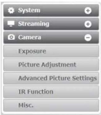
Figure 101: Camera Section Tabs
Every screen in the Camera section includes the following pushbuttons to the left of the Live View window:
| Zoom |  |  |  | Click the Wide or Tele Zoom button to implement continuous zoom adjustment. Click Reset to return the zoom to the default setting. |
| Step |  |  |  | Click the Wide or Tele Step button to alternate the zoom between wide and telephoto views within a user-defined range of steps, which can be selected from the drop-down menu. |
| Focus |  |  |  | Click the Near or Far Focus button to implement continuous focus adjustment. Click Reset to return the zoom to the default setting. |
| Step |  |  |  | Click the Near or Far Step button to alternate the focus between near and far views within a user-defined range, which can be selected from the drop-down menu. |
| AF |  | Click the Push AF button once to adjust zoom or focus. | ||
9.5.1 Exposure
The Exposure screen is used to configure lens settings and exposure modes. The exposure is the amount of light received by the image sensor and is determined by the amount of exposure by the sensor (shutter speed), and other exposure parameters.
Administrators may either allow the camera to automatically select an exposure level using a programmed algorithm or choose the level themselves. The smaller the number (the higher the shutter speed) that the administrator selects, the lower the exposure level and vice versa.
Even in Auto Mode, a Minimum Shutter Speed may be set from the drop-down menu to ensure a maximum level of exposure. In Manual Mode, the administrator can choose fixed shutter speeds from a drop-down menu.
Exposure Mode
The bottom section of the screen enables you to select one of three exposure modes: P-Iris Priority, Auto P-Iris (default), or Manual Mode. Administrators may either allow the camera to automatically select an exposure level using a programmed algorithm or choose the level themselves.
Exposure Value (CM-6208 only)
The user can set the Exposure value for each exposure mode on the CM-6208. This is a number that represents a combination of a camera's shutter speed and aperture setting (f-number), which brightens or darkens the scene accordingly. Select from the following options: -2, -5/3, -4/3, -1, -2/3, -1/3, 0, 1/3, 2/3, 1, 4/3, 5/3, or 2. The higher the number, the brighter the image. The default setting is 0.

Figure 102: CM-6208 Exposure Screen
P-Iris Priority Mode
In P-iris Priority mode, the iris does not adjust, regardless of the light level. If, however, the light level goes below the P-iris setting, the iris will fully open in a single step if the Auto Adjustment option is turned on.

Figure 103: Exposure Mode P-Iris Priority Settings
The following setting are available:
- Iris Size Setting – Select the following buttons

The minus (-) button closes the iris.

The plus (+) button opens the iris.

The reset button is for resetting the P-iris

The radial button is for automatically selecting the optimal iris exposure
- Auto Adjustment – From the drop-down menu, select On or Off. When enabled, if the lighting level falls below the set P-iris level, the iris will jump to its fully-opened position.
- Min Shutter Speed – When selecting this mode, the camera's shutter speed automatically achieves a consistent video output level. Users can select a suitable shutter speed according to the environmental luminance.
The shutter speed range is selectable on the drop-down menu from 1/2 to 1/500 sec (NTSC) and 1/1.5 to 1/425 sec (PAL). The following table lists the options.
| P-Iris PriorityMin Shutter Speed | |
| PAL | NTSC |
| 1/425 | 1/500 |
| 1/300 | 1/350 |
| 1/215 | 1/250 |
| 1/150 | 1/180 |
| 1/120 | 1/120 |
| 1/100 | 1/100 |
| 1/75 | 1/90 |
| 1/50 | 1/60 |
| 1/25 | 1/30 |
| 1/12 | 1/15 |
| 1/6 | 1/8 |
| 1/3 | 1/4 |
| 1/1.5 | 1/2 |
Click SET when you finish configuring the settings.
Auto P-Iris Mode
Auto-P iris is the default mode. It automatically and smoothly adjusts the iris when the light level drops to a point where it is insufficient to support the P-iris setting. A Minimum Shutter Speed may be set from the drop-down menu to ensure a maximum level of exposure.

Figure 104: Exposure Mode Auto P-Iris Settings
The following settings are available:
- Min Shutter Speed – When selecting this mode, the shutter is completely open and the exposure priority is given to the iris. Shutter speed and AGC circuit function automatically in cooperating with the iris to achieve a consistent exposure output.
The shutter speed range is from 1/2 to 1/30 sec (NTSC) and 1/1.5 to 1/25 sec (PAL). The following table lists the options.
| Auto IrisMin Shutter Speed | |
| PAL | NTSC |
| 1/25 | 1/30 |
| 1/12 | 1/15 |
| 1/6 | 1/8 |
| 1/3 | 1/4 |
| 1/1.5 | 1/2 |
- F Number – Displays the current F-Stop setting.
Click SET when you finish configuring the settings.
Manual Mode
Manual mode is used generally where light levels are fixed and the auto settings do not provide the perfect exposure. It is recommended for scenes such as indoor scenes, where there is a fixed lighting contrast and a constant, precise exposure is required.
Manual Mode opens the iris completely with a fixed gain to a fixed shutter speed. Users can select a suitable shutter speed according to the environmental luminance. Increasing the value of the fixed shutter increases the amount of light entering the sensor. This allows a brighter and more detailed image. Similarly, utilizing gain and increasing its level increases the sensitivity of the image sensor, which brightens the image and add details. This increases the level of noise in the image.
In Manual Mode, the administrator can select a fixed shutter speed and gain from drop-down menus. The smaller the shutter speed number (the higher the shutter speed), the lower the exposure level. The higher the gain, the brighter the picture.

Figure 105: Exposure Mode Manual Settings
The following setting are available:
- Iris Size Setting – Select the following buttons

The minus (-) button closes the iris.

The Plus (+) button opens the iris.

The reset button is for resetting the P-iris

The radial button is for automatically selecting the optimal iris exposure
- Shutter Speed – The fixed shutter speed is selectable from 1/2 to 1/10000 sec (NTSC) and 1/1.5 to 1/10000 sec (PAL). Users should select the suitable shutter speed according to the environmental luminance. The following table lists the options.
| Manual Mode Fixed Shutter Speeds | |
| PAL | NTSC |
| 1/10000 | 1/10000 |
| 1/3500 | 1/3000 |
| 1/2500 | 1/2000 |
| 1/1250 | 1/1000 |
| 1/600 | 1/725 |
| 1/425 | 1/500 |
| 1/300 | 1/350 |
| 1/215 | 1/250 |
| 1/150 | 1/180 |
| 1/120 | 1/120 |
| 1/100 | 1/100 |
| 1/75 | 1/90 |
| 1/50 | 1/60 |
| 1/25 | 1/30 |
| 1/12 | 1/15 |
| 1/6 | 1/8 |
| 1/3 | 1/4 |
| 1/1.5 | 1/2 |
- Gain – A nominal video signal level is usually 1 volt peak-to-peak for composite video, 0.7 volts for component or RGB video, or 0.3 volts for the chrominance subsection, at which level a fully saturated picture is transmitted to the acceptor. However, for cases where the video signal is attenuated, a low-noise, high-gain analog amplifier is built into quality video processing equipment. This amplifier provides video gain control whereby the video signal can be boosted or reduced. Dark pictures caused by low level lighting are easily adjusted. The Gain drop-down menu turns the video gain Off or moves it in steps from 1 to 9.
Click SET when you finish setting the gain.
9.5.2 Picture Adjustment
Adjustment of some qualities of the video is made possible by selecting Picture Adjustment in the Camera tab. Brightness, Sharpness, Contrast, Saturation and Hue may all be adjusted via drop-down menus from this window, as shown below.
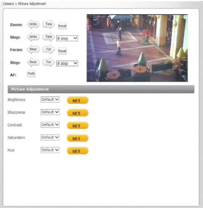
Figure 106: Camera Settings Screen – Picture Adjustment
Brightness
You can adjust the image's brightness by adjusting this parameter. Select from the range between -12 to +13. To increase video brightness, select a larger number. The default setting is DEFAULT. Click SET to confirm the new setting.
Sharpness
Increasing the sharpness level can make the image look sharper, especially enhancing the object's edge. Select from the range between 0 to +15. The default setting is DEFAULT. Click SET to confirm the new setting.
Contrast
Camera image contrast level is adjustable. Select from a range of -6 to +19. The default setting is DEFAULT. Click SET to confirm the new setting.
Saturation
Camera image saturation level is adjustable. Select from a range of -6 to +19. The default setting is DEFAULT. Click SET to confirm the new setting.
Hue
Camera image hue level is adjustable: select from a range of -12 to +13. The default setting is DEFAULT. Click SET to confirm the new setting.
9.5.3 Advanced Picture Settings
The Advanced Picture Settings screen is used configuring the following settings:
White Balance
Backlight
WDR Function
Shutter WDR
3DNR
2DNR
ColorNR
White Balance
Options for controlling the camera's white balance (color balance) are shown below.
![Camera > Advance Picture Settings Zoom: Wide Tele Reset Step: Wide Tele 8 step Focus: Near Far Reset Step: Near Far 8 step AF: Push ADVANCE PICTURE SETTINGS White Balance ● Auto ○ ATW ○ One Push ○ Manual Rgain [0..127] 57 Bgain [0..127] 54 SET Backlight Off SET WDR Function Mid SET 3DNR 3DNR Low SET 2DNR On SET ColorNR Color Hi SET SET](/content/2026/05/934891/images/ee347a7ccd5d6e8ceb46c45dfb0bfd00a109cc5d408dab783ace20a95d0e22d8.jpg)
Figure 107: CM-6208 Advanced Picture Settings Screen – White Balance
A camera needs to find a reference color temperature as a way of measuring the quality of a light source for calculating all other colors. The unit for measuring this ratio is in Kelvin (°K) degrees. You can select one of the White Balance control modes according to the operating environment. The table below shows the color temperature of some light sources for reference.
| Light Sources | Color Temperature (in K°) |
| Cloudy Sky | 6,000 to 8,000 |
| Noon Sun and Clear Sky | 6,500 |
| Household Lighting | 2,500 to 3,000 |
| 75-watt Bulb | 2,820 |
| Candle Flame | 1,200 to 1,500 |
Four white balance modes are available:
- Auto – The Auto Balance White mode computes the white balance value output using color information from the entire screen. It is suitable for an environment with a light source color temperature in the range of approximately 2,700 \~ 7,500K. This is the default setting for CM-6208.
- ATW (Auto Tracking White Balance) – The Auto Tracking White Balance function automatically adjusts the white balance in a scene while temperature color is changing. The ATW Mode is suitable for an environment with a light source color temperature in the range of approximately 2500 \~ 10,000K. This is the default setting for CM-6204.
- One Push – This button activates the factory-optimized setting for white balance. This setting may not be ideal for every lighting environment.
- Manual – In this mode, you can manually change the white balance value. You can select a number between 0 – 127 for either/both Rgain and Bgain to increase the red and/or blue luminance.
Click SET to confirm the new settings.
Backlight (CM-6208 only)
Backlight compensation is used in images where a bright light source is behind the subject of interest. Without backlight compensation, the subject would normally appear in silhouette. The backlight function of the camera allows it to adjust the exposure of the entire image to properly expose the subject in the foreground.
Select On or Off. The default setting is Off.
Click SET to confirm the new settings.
![Camera > Advance Picture Settings Zoom: Wide Tele Reset Step: Wide Tele 8 step Focus: Near Far Reset Step: Near Far 8 step AF: Push ADVANCE PICTURE SETTINGS White Balance ● Auto ○ ATW ○ One Push ○ Manual Rgain [0..127] 57 Bgain [0..127] 54 SET Backlight Off SET WDR Function Mid SET 3DNR 3DNR Low SET 2DNR On SET ColorNR Color Hi SET SET](/content/2026/05/934891/images/2b8a03379fb5181b637ecdca76c29ea6b69a85363be008f3567117100d303e68.jpg)
Figure 108: CM-6208 Advanced Picture Settings Screen – Backlight
WDR Function
WDR (Wide Dynamic Range) resolves high contrast or changing light issues in order to enhance the image quality. It does this by producing a larger amount of details in both the dark and bright areas of the image. Such scenes combine areas with different lighting conditions, where some areas are very bright and others are dark. If this function was not used, the image either would be overexposed or too bright in bright areas and completely dark in dark areas.
The WDR function setting is adjustable among Off, Low, Mid and Hi. A higher level of WDR represents wider dynamic range, so that the IP camera can capture a greater scale of brightness. The default setting is Mid.
Click SET to confirm the new settings.
![Camera > Advance Picture Settings Zoom: Wide Tele Reset Step: Wide Tele 8 step Focus: Near Far Reset Step: Near Far 8 step AF: Push ADVANCE PICTURE SETTINGS White Balance ● Auto ○ ATW ○ One Push ○ Manual Rgain [0..127] 57 Bgain [0..127] 54 SET Backlight Off SET WDR Function Mid SET 3DNR 3DNR Low SET 2DNR On SET ColorNR Color Hi SET SET](/content/2026/05/934891/images/0227c59b8f30e418d49e83e67ca13a48eaf8c8c6ed6acff4f751bb8531777c94.jpg)
Figure 109: Advanced Picture Settings Screen – WDR Function
Shutter WDR (CM-6204 only)
The Shutter WDR (Wide Dynamic Range) function, also known as True WDR, is a form of multi-exposure WDR that resolves high contrast or changing light issues and creates a constant video output level.
![Camera > Advance Picture Settings Zoom: Wide Tele Reset Step: Wide Tele 8 step Focus: Near Far Reset Step: Near Far 8 step AF: Push ADVANCE PICTURE SETTINGS White Balance Auto ATW One Push Manual Rgain [0..127] 57 Bgain [0..127] 54 SET WDR Function Mid Shutter WDR On SET 3DNR 3DNR Low SET 2DNR On SET ColorNR Color Hi SET SET](/content/2026/05/934891/images/d692a8770f2c04b0fce492f13f9ba05debb96150c243e2fe336941da64e0627c.jpg)
Figure 110: Advanced Picture Settings Screen-Shutter WDR
A combination of slow- and fast-exposure shutters is used to create a new image with a wide dynamic range. The camera uses an algorithm to determine the optimal mix of light and dark regions within the scene from the two shutters in order to adjust the wide dynamic range of the scene.

natural_image
Interior view of a modern meeting room with large windows, a potted plant, and a desk (no visible text or symbols)Figure 111: Shutter WDR On
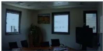
natural_image
Interior view of a conference room with presentation screens and wooden desks (no visible text or symbols)Figure 112: Shutter WDR Off
The Shutter WDR setting is selectable between On or Off:
- When On is selected, the image has a wide dynamic range, so that the IP camera can capture a greater scale of brightness.
- Selecting Off disables this function. This is the default setting.
Click SET to confirm the new settings.
Noise Reduction
The noise reduction function consists of three settings:
• 3DNR
- 2DNR
- ColorNR
Noise reduction settings are used to reduce or eliminate artifacts that can limit the ability to positively identify an object. There are two types of noise: luminance and color (chroma) noise.
3DNR and 2DNR settings reduce luminance noise, which is composed of dots of various brightness levels (black, white and gray). It is not recommended to completely eliminate luminance noise, which can result in unnatural images. 3DNR and 2DNR settings should be configured after configuring ColorNR.
![Camera > Advance Picture Settings Zoom: Wide Tele Reset Step: Wide Tele 8 step Focus: Near Far Reset Step: Near Far 8 step AF: Push ADVANCE PICTURE SETTINGS White Balance ● Auto ○ ATW ○ One Push ○ Manual Rgain [0..127] 57 Bgain [0..127] 54 SET Backlight Off SET WDR Function Mid SET 3DNR 3DNR Low SET 2DNR On SET ColorNR Color Hi SET](/content/2026/05/934891/images/23ff915083fa86fb356e7b50265de1d86a4584ffaea2bb931bc62c1aa09f1ba8.jpg)
Figure 113: Advanced Picture Settings Screen – Noise Reduction
3DNR
3DNR (3D Noise Reduction) provides superior noise reduction and is recommended for use in in extra low-light conditions. It is especially useful for reducing blur with moving objects. The 3DNR function reduces image noise/snow in low-light conditions by comparing adjacent frames. A higher level of 3DNR generates relatively enhanced noise reduction, although it creates more motion blur than 2DNR on moving objects.
The noise reduction is adjustable from Off, 3DNR Low, 3DNR Mid, and 3DNR Hi. The default setting is 3DNR Low. Click SET to confirm the new settings.
2DNR
2DNR (2D Noise Reduction) analyzes individual frames pixel by pixel and frame by frame to eliminate environmental noise and deliver optimized image quality, especially in low-light conditions. 2DNR tends to produce superior results for moving objects when applied to areas in the field of view where movement is present. However, it is less precise than 3DNR.
Settings include On and Off. The default setting is On. Click SET to confirm the new settings.
ColorNR
The ColorNR setting controls the noise displayed as red, green and blue dots that are visible between light and dark areas. Four settings are available: Off, Color Low, Color Med, and Color Hi. The highest setting (Color Hi) maximizes the blending of the color noise with the image, effectively removing the dots, while the Color Low setting minimizes the blending. The Off setting disables this function. Click SET to confirm the new settings. The default setting is Color Hi.
9.5.4 IR Function
The IR Function setting activates two functions:
• The IR Cut (IRC) filter for electronic day/night operation (IR mode)
• The IR LED illuminator for use in low-light conditions or at night

Figure 114: IR Function Screen
IR Mode
The day/night IRC switching mechanism operates according to the ambient light level rather than activation of the IR LED mode. The IR Mode drop-down menu enables you to select from Auto/On/Off/Smart modes. The default mode is Smart. Following is an explanation of the four settings:
- Auto Mode – The camera converts from Day mode (color) to Night mode (monochrome) automatically at nighttime or in low light conditions. When there is sufficient light, the camera converts automatically from Night mode to Day mode.
- On – Activates IR mode (puts camera into monochrome/Night mode).
- Off – Deactivates IR mode (puts camera into color/Day mode).
- Smart – Smart mode enhances monochrome/Night mode stability when IR illumination is dominant and keeps the camera from switching between Day and Night modes. In this mode, the IR Cut filter is on (i.e. monochrome/Night mode) when the IR LED illuminator also is activated. This prevents the camera from returning to color/Day mode.
Click SET to confirm the new setting.
IR LED Illuminator
This setting is used in low-light conditions or at night. IR LED lights are turned On or Off, depending on the light sensor. The default mode is Auto. Two settings are available:
• Auto – The light sensor operates automatically.
- Off – The IR light is always off.
Click SET to confirm the new setting.
Day/Night Threshold
Set the threshold at which you want to activate the IR function:
- For the daytime to nighttime threshold, from the upper drop-down list, select a number between 1-9, where 1 is darker and 9 is brighter.
- For the nighttime to daytime threshold, from the upper drop-down list, select a number between 1-9, where 1 is darker and 9 is brighter.
Click SET to confirm the new setting.
IR Compensation
From the drop-down list, set the IR Compensation to On or Off. Setting IR Compensation to On compensates for the reflection of infrared light emitted from the camera onto reflective objects, thus improving image sharpness and definition. Without IR compensation, objects may appear blurred. IR Compensation is enabled by default.
Click SET to confirm the new setting.
9.5.5 Misc.
From the Misc. (Miscellaneous) tab, you can set the Digital Zoom and TV System.

Figure 115: Camera Settings Screen – Digital Zoom

Note:
After changing TV System settings, the camera restarts automatically. You must re-enter the unit's IP address again in your browser in order to use the unit with the new settings.
Digital Zoom Settings
The camera's digital zoom is adjustable from x2 to x10. Select the desired zoom or Off. Click SET to confirm the new setting.
TV System Settings
Select the video system setting: 25 fps (PAL) or 30 fps (NTSC). The default TV system is 30 fps (NTSC). Click SET to confirm the setting.
9.6 Log Out
Selecting the Logout link on the Home page to close the session. The following message appears:

Figure 116: Login Message
Upon clicking Login, the Login dialog box opens. See Figure 26: Login Dialog Box.

10 Appendices
• CM-6204 Technical Specifications
• CM-6208 Technical Specifications
- Internet Security Settings
• Install UPnP Components
• Deleting and Installing the Web Player
- Deleting Temporary Internet Files
- Mounting Accessories
A.1. CM-6204 Technical Specifications
| Camera | ||
| Image Sensor | 1/3" 2688 x 1520 Progressive Scan BSI CMOS | |
| Effective Pixels | 2560 x 1440 (H x V) | |
| Shutter Speed | 1.0 to 1/10,000 (auto) | |
| Digital Slow Shutter (DSS) | 1/1 to 1/25 or 1/30 with ≤ 32x sensitivity boost in day/night mode | |
| Sensitivity | 0.3 Lux @F1.4 in color mode; 0.04 Lux @ F1.4 in night mode with IR illuminator ON, measured with DSS OFF at 30 IRE | |
| Enclosure | Tamper-resistant surface mount plastic case | |
| Lens | CM-6204-11-I | CM-6204-21-I |
| Lens Type | Varifocal motorized P-Iris with auto-focus and True Day/Night | |
| Lens Options | 3-8mm, F1.4 | 7-22mm, F1.4 |
| Horizontal Viewing Angle | 96-38° | 42-14° |
| Video | ||
| Video Compression | H.264 Main/High Profile (MPEG-4 Part 10), triple-streaming | |
| Video Resolution | QHD (2560 x 1440)/Full HD 1080p/SXGA (1280 x 1024)/HD 720p/XVGA/SVGA/D1/VGA/CIF/QVGA | |
| Video Streaming(Maximum Performance) | H.264 25/30 fps (PAL/NTSC) @ QHD or simultaneous QHD @ 12/15 fps + D1 @ 12/15 fps (PAL/NTSC); QHD + D1 each at 25 fps (PAL/NTSC); or H.264 25 fps @ QHD @ 12/15 fps + HD 720p @ 12/15 fps + D1 @ 12/15 fps | |
| Rate Control Option | CBR (64Kbps - 20,480Kbps), VBR | |
| Operation | ||
| Image Setting | Brightness | Manual |
| Exposure | Auto-iris, Auto/Fixed Shutter | |
| Sharpness | Manual | |
| Contrast | Manual | |
| Hue | Manual | |
| White Balance | Auto/Indoor/Outdoor/ATW/Manual | |
| Gain (AGC) | Automatic | |
| Backlight | On/Off | |
| Digital Zoom | Supported (x2 to x10) | |
| WDR | WDR (On/Off + 3 levels) and True Multi-Shutter WDR (On/Off) | |
| Noise Reduction | 3DNR: On/Off + 3 levels (with Latitude), On/Off + 3 levels (without Latitude); 2DNR (On/Off); ColorNR (On/Off + 3 levels) | |
| Privacy Mask(Video Mask) | Web interface: On/Off. Up to five embedded web interfaces are supported in the streaming video output, but are not supported by Latitude. In the Latitude interface, the Privacy Mask is independent of the camera's on-screen display and is not embedded. | |
| IR Function | Day/Night (Auto/On/Off/Smart) | |
| Operation | ||
| Audio | Two-way Audio | Line out/Line in |
| Compression | G.711/G.726 (not supported by Latitude) | |
| Alarm | Input | 1x 5V 10kΩ pull up dry contact |
| Output | 1x Photo Relay Output 300V DC/AC @ 130mA maximum | |
| Signal-to-Noise Ratio | ±50dB | |
| Event Notification | HTTP, FTP, SMTP | |
| Languages | English, German, Spanish, French, Italian, Japanese, Korean, Portuguese, Russian, Simplified Chinese, and Traditional Chinese | |
| Analytics | ||
| Motion Detection | On/Off, plus sampling pixel interval, detection level, sensitivity level, and time interval settings. | |
| Regions of Interest | Web interface: Configurable up to 10 ROI masks.Latitude interface: Configurable up to six ROI masks. | |
| Motion Metadata | Streaming and recorded video includes per frame level motion metadata. Motion metadata is archive searchable by ROI via the Latitude Control Center user interface. | |
| Triggered Actions | Notifications, On-Event Recording and Relay Output Command.Includes configurable alarms and broad range of recording on detection of video and snapshots. | |
| Tampering Alarm | On/Off, plus duration, on-event notification, recording to SD card, recording to NAS, and more are supported as events in Latitude. | |
| IR Illuminator | ||
| Working Distance | 40 meters (131 ft.) at 60° | |
| Wavelength | 850nm | |
| IR Sensitivity | Yes (680-1100nm) | |
| LEDs | 6 | |
| Network | ||
| Interface | 10/100/1000Mbps Ethernet, Auto-sensing, Full/Half-Duplex | |
| Protocols | IPv4/v6, TCP/IP, UDP, RTP, RTSP, HTTP, HTTPS, ICMP, FTP, SMTP, DHCP, PPPoE, UPnP, IGMP, SNMP, SNTP, QoS, IEEE 802.1X, ONVIF Version 2.4 Profile S | |
| Password Levels | User and Administrator | |
| Security | HTTPS, IP Filter, IEEE 802.1x | |
| Firmware Upgrade | Flash memory for upgrade of camera firmware over the network (4GB Flash/8GB RAM) | |
| Operating Systems | Windows XP, 7, 8, and 8.1 | |
| Internet Browser | Internet Explorer (IE 9, 10, and 11) | |
| User Accounts | 20 | |
| Mechanical | ||
| Connectors | Power | 3-pin terminal block |
| Ethernet | RJ45 | |
| Audio | 1x Line-in and 1x Line-out 1.5mm audio jack | |
| Alarm | 4-pin terminal block with 2-pin alarm input and 2-pin relay output | |
| Analog Video | 1.0V p-p/75Ω, BNC (continuously enabled) | |
| LED Indicator | Power, Link, ACT | |
| Enclosure Standards | IP66, NEMA 4, 1K10 vandal-resistant | |
| Mechanical IR Cut Filter | Included | |
| Bubble Rating | IK10 Vandal-Resistant Polycarbonate | |
| Bubble F-Stop | Clear Bubble: F0.0, Smoke Bubble (optional): F1.0 | |
| Pan/Rotate/Tilt | 355° pan/ ±100° rotate/80° tilt | |
| MicroSDXC Card Recording | Up to 128GB, Class 10 (card not included) | |
| Physical | ||
| Dimensions (Diameter x W) | ∅ 163 x 104 mm (6.43 x 4.09 in.) | |
| Weight | 0.82 kg (1.81 lbs.) | |
| Electrical | ||
| Power Consumption | Indoor | 6W |
| Outdoor | 13W with heater and IR | |
| Power Source | 12VDC (± 10%), 24VAC (± 10%), PoE (802.3af Class 0) | |
| Environmental | ||
| Operating Temperature | -40° to 50°C (-40° to 122°F) with heater-25°C to 50°C (-13° to 122°F) for cold start with POE | |
| Humidity | 10-95% non-condensing | |
| General | ||
| Regulatory | US | FCC 47 CFR Part 15, Subpart B, Class A; CISR Pub. 22; UL 60950 |
| International | CE (EN 55022-1998 Class A; EN 50130-4; EN 60950); ICES-003; RoHS; WEEE | |
| Warranty | Four-year limited warranty | |
A.2. CM-6208 Technical Specifications
| Camera | ||
| Image Sensor | 1/1.7" 4072 x 3076 (12 MP) Progressive Scan BSI CMOS | |
| Effective Pixels | 3840 x 2160 (H x V) | |
| Shutter Speed | 1.0 to 1/10,000 (auto) | |
| Digital Slow Shutter (DSS) | 1/1 to 1/25 or 1/30 with ≤ 32x sensitivity boost in day/night mode | |
| Sensitivity | 0.3 Lux @F1.4 in color mode; 0.04 Lux @ F1.4 in night mode with IR illuminator ON, measured with DSS OFF at 30 IRE | |
| Enclosure | Tamper-resistant surface mount plastic case | |
| Lens | CM-6208-11-I | CM-6208-21-I |
| Lens Type | Varifocal Motorized F1.4 P-Iris with auto-focus and True Day/Night | |
| Lens Options | 3.5-8mm | 9-22mm |
| Horizontal Viewing Angle | 116-50° | 45-18° |
| Video | ||
| Video Compression | H.264 and MJPEG | |
| Video Resolution | UHD 4K (3840 x 2160)/Full HD 1080p/SXGA (1280 x 1024)/HD 720p/XVGA/SVGA/D1/VGA/CIF/QVGA | |
| Video Streaming (Maximum Performance) | H.264 25/30 fps @ 4K (PAL/NTSC); 4K + D1 at 25 fps each (PAL/NTSC); H.264 12/15 fps @ 4K or simultaneous 4K + Full HD 1080p + HD 720p + D1 | |
| Rate Control Option | CBR (64Kbps - 20,480Kbps), VBR | |
| Operation | ||
| Image Setting | Brightness | Manual |
| Exposure | Auto-iris, Auto/Fixed Shutter | |
| Sharpness | Manual | |
| Contrast | Manual | |
| Hue | Manual | |
| White Balance | Auto/Indoor/Outdoor/ATW/Manual | |
| Gain (AGC) | Automatic | |
| Backlight | On/Off | |
| Digital Zoom | Supported (x2 to x10) | |
| WDR | On/Off + 3 levels | |
| Noise Reduction | 3DNR: On/Off + 3 levels (with Latitude), On/Off + 3 levels (without Latitude); 2DNR (On/Off); ColorNR (On/Off + 3 levels) | |
| Privacy Mask (Video Mask) | Web interface: On/Off. Up to five embedded web interfaces are supported in the streaming video output, but are not supported by Latitude. In the Latitude interface, the Privacy Mask is independent of the camera's on-screen display and is not embedded. | |
| IR Function | Day/Night (Auto/On/Off/Smart) | |
| Operation | ||
| Audio | Two-way Audio | Line out/Line in |
| Compression | G.711/G.726 (not supported by Latitude) | |
| Alarm | Input | 1x 5V 10kΩ pull up dry contact |
| Output | 1x Photo Relay Output 300V DC/AC @ 130mA maximum | |
| Signal-to-Noise Ratio | ±50dB | |
| Event Notification | HTTP, FTP, SMTP | |
| Languages | English, German, Spanish, French, Italian, Japanese, Korean, Portuguese, Russian, Simplified Chinese, and Traditional Chinese | |
| Analytics | ||
| Motion Detection | On/Off, plus sampling pixel interval, detection level, sensitivity level, and time interval settings. | |
| Regions of Interest | Web interface: Configurable up to 10 ROI masks.Latitude interface: Configurable up to six ROI masks. | |
| Motion Metadata | Streaming and recorded video includes per frame level motion metadata. Motion metadata is archive searchable by ROI via the Latitude Control Center user interface. | |
| Triggered Actions | Notifications, On-Event Recording and Relay Output Command.Includes configurable alarms and broad range of recording on detection of video and snapshots. | |
| Tampering Alarm | On/Off, plus duration, on-event notification, recording to SD card, recording to NAS, and more are supported as events in Latitude. | |
| IR Illuminator | ||
| Working Distance | 40 meters (131 ft.) at 60° | |
| Wavelength | 850nm | |
| LEDs | 6 | |
| Network | ||
| Interface | 10/100/1000Mbps Ethernet, Auto-sensing, Full/Half-Duplex | |
| Protocols | IPv4/v6, TCP/IP, UDP, RTP, RTSP, HTTP, HTTPS, ICMP, FTP, SMTP, DHCP, PPPoE, UPnP, IGMP, SNMP, SNTP, QoS, IEEE 802.1X, ONVIF Version 2.4 Profile S | |
| Password Levels | User and Administrator | |
| Security | HTTPS, IP Filter, IEEE 802.1x | |
| Firmware Upgrade | Flash memory for upgrade of camera firmware over the network (1GB Flash/8GB RAM) | |
| Operating Systems | Windows XP, 7, 8, and 8.1 | |
| Internet Browser | Internet Explorer (IE 9, 10, and 11) | |
| User Accounts | 20 | |
| Mechanical | ||
| Connectors | Power | 3-pin terminal block |
| Ethernet | RJ45 | |
| Audio | 1x Line-in and 1x Line-out 1.5mm audio jack | |
| Alarm | 4-pin terminal block with 2-pin alarm input and 2-pin relay output | |
| Analog Video | 1.0V p-p/75Ω, BNC (continuously enabled) | |
| LED Indicator | Power, Link, ACT | |
| Weatherproof Standard | IP66 | |
| Mechanical IR Cut Filter | Included | |
| Bubble Rating | IK10 Vandal-Resistant Polycarbonate | |
| Bubble F-Stop | Clear Bubble: F0.0, Smoke Bubble (optional): F1.0 | |
| Pan/Rotate/Tilt | 355° pan/ ±100° rotate/80° tilt | |
| MicroSDXC Card Recording | Up to 128GB, Class 10 microSDXC card (card not included) | |
| Physical | ||
| Dimensions(Diameter x W) | ∅163 x 104 mm (6.43 x 4.09 in.) | |
| Weight | 0.82 kg (1.81 lbs.) | |
| Electrical | ||
| Power Consumption | Indoor | 6W |
| Outdoor | 13W with heater and IR | |
| Power Source | 12VDC (± 10%), 24VAC (± 10%), PoE (802.3af Class 0) | |
| Environmental | ||
| Operating Temperature | -40° to 50°C (-40° to 122°F) with heater-25°C to 50°C (-13° to 122°F) for cold start with POE | |
| Humidity | 10-95% non-condensing | |
| General | ||
| Regulatory | US | FCC 47 CFR Part 15, Subpart B, Class A; CISR Pub. 22; UL 60950 |
| International | CE (EN 55022-1998 Class A; EN 50130-4; EN 60950); ICES-003; RoHS; WEEE | |
| Warranty | Four-year limited warranty | |
A.3. Internet Security Settings
If the existing ActiveX certificate is old or invalid, the ActiveX installation may fail in systems that are not connected to the Internet, which therefore cannot update their security certificates. In this case, the Setup.exe file in the ActiveX folder on the supplied CD should be run. The user can then continue with the installation.
If ActiveX control installation is blocked, either set Internet security level to default or change ActiveX controls and plug-in settings.
To set the default Internet security level
-
Start Internet Explorer (IE).
-
From the Command Bar toolbar, select Tools and select Internet Options from the menu that appears.

Figure 117: Command Bar Toolbar – Select Internet Options
In the Internet Options window that appears, select the Security tab.
Select in Select a zone to view or change security settings.
If the settings are not defined as default, select Default Level and move the Allowed levels for this zone slider to Medium-high and select OK.

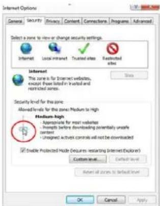
Figure 118: Internet Options Screen
Close all browsers and reopen so that the settings take effect.
ActiveX Controls and Plug-in Settings
To create a custom level
-
Start Internet Explorer (IE).
-
From the Command Bar toolbar, select Tools and select Internet Options from the menu that appears.

Figure 119: Command Bar Toolbar – Internet Options
In the Internet Options window that appears, select the Security tab.

If not already selected, select , then select Custom Level.
In the dialog that appears, under ActiveX controls and plug-ins set ALL the following options (listed below) to Enable or Prompt:
• Automatic prompting for ActiveX controls
• Binary and script behaviors
- Download signed ActiveX controls
- Download using ActiveX controls
- Initialize and script ActiveX not marked as safe
- Run ActiveX controls and plug-ins
- Script ActiveX controls marked safe for scripting
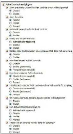
Figure 120: Schedule Screen
Click OK to accept the settings and close the Security screen.
Click OK to close the Internet Options screen.
Close the browser window and restart IE again to access the camera.
A.4. Install UPnP Components
Follow the instructions below to enable UPnP so that the camera can be discovered and displayed in Network locations under Other Devices:
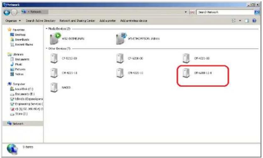
To enable UPnP discovery in Windows 7, 8, and 8.1

(Start) and select Control Panel.
- Click Network and Internet.

Network and Internet
View network status and tasks
Choose homegroup and sharing options
- Click Network and Sharing Center.

Network and Sharing Center
View network status and tasks Connect to a network
Add a wireless device to the network
View network computers and devices
- Click Change advanced sharing settings.
Control Panel Home
Change adapter settings
Change advanced sharing
settings
- Expand the Home or Work node, select Turn on network discovery.

- Click Save Changes.

Note:
Network discovery requires that the DNS Client, Function Discovery Resource Publication, SSDP Discovery, and UPnP Device Host services are started, that network discovery is allowed to communicate through Windows Firewall, and that other firewalls are not interfering with network discovery.
To check that the UPnP Device Host services are running
- Click (Start) and type in the Search programs and files field services.msc and then select services.msc from the displayed Programs. The Services manager dialog box appears.

- In the Services manager dialog box, scroll down the list to UPnP Device Host and verify that it shows the status Started. If Started is not displayed, right-click and select Start from the shortcut menu.
A.5. Installing and Deleting the Web Player
The Quasar Player enables you to view the camera's user interface.
If this is a first-time installation of the camera, the Quasar Player installation wizard opens after accessing the camera.

Figure 121: Quasar Player Installation Wizard
To install the Quasar Player
- Click Next. The Player is installed.
- Click Finish when the next screen opens. The installation is completed. Quasar Player is displayed in the list of installed programs.
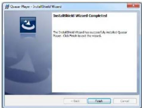
Figure 122: Quasar Player Installation Completed
Users who have previously installed the DVPlayer or DCViewer web player in the PC should first delete the existing player file from the PC and then install the Quasar Player before accessing the camera.
To delete an existing DVPlayer or DCViewer file

- Click Start and select Control Panel. The Control Panel opens.
- In the Control Panel, click Uninstall a program.

Programs Uninstall a program Get programs
-
From the installed program list, select DVPlayer or DCViewer.
-
On the banner bar, click Uninstall.
- If prompted to confirm the Uninstall, click Yes.
- After deleting the previous player file, you must clear your computer's cache memory.
To clear your computer's cache memory
- In the Control Panel, click Internet Options. The Internet Properties dialog box opens.
- From the Browsing History section, click Delete. The Delete Browsing History dialog box opens.
- From the Delete Browsing History dialog box, select Preserve Favorites website data, Temporary Internet files and website files, Cookies and website data, and Tracking Protection, ActiveX Filtering and Do Not Track.
- Click Delete. The Internet Properties dialog box opens.
- Click OK. Your computer's cache memory is deleted. After the cache is cleared, the Quasar Player installation wizard opens.
- Follow instructions above to install the Quasar Player.
A.6. Deleting Temporary Internet Files
To improve browser performance, it is recommended to clean up all of the temporary Internet files.
To delete temporary Internet files
- In Internet Explorer (IE), from the Command Bar toolbar, click Tools and select Internet Options from the menu that appears.
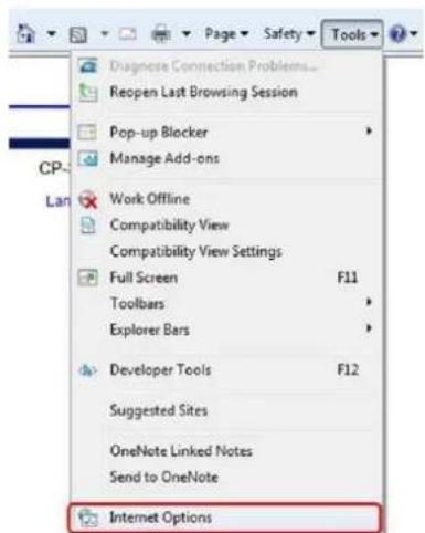
- In the General tab in the Internet Options dialog box, click Delete.
- In the Delete Browser History dialog box that appears, select Temporary Internet files. Deselect Cookies and History to keep this data. Then click Delete.

A.7. Mounting Accessories
The following mounting accessories are available from FLIR for installation of your Quasar Gen II CM-620x Series Mini-Dome IP Camera. For more information on available options, contact your FLIR sales representative or visit www.FLIR.com/security to request details on where to get the accessories you need.
| Image | Name | Description |
 | CM-CAPX-IND-W | Indoor wall mounting kit. Includes pendant cap with 18cm (7.1 in.) threaded wall mount bracket. |
 | CM-CAPX-IND-P | Indoor pendant mounting cap. Ready for 34" conduit or 1-1/2" threaded mount. |
 | CM-CAPX-OUT-W | Outdoor wall mounting kit. Includes sunshield and pendant cap with 18cm (7.1 in.) threaded wall mount bracket. |
 | CM-CAPX-OUT-P | Outdoor pendant cap. Includes 1-1/2" male pipe threaded mount and 34" female EMT conduit compatibility. |
 | CM-RCSD-G2 | Recessed mounting kit. Included peel and stick template, top-mounted 4S electrical box attachment points. For maximum surface thickness of 42mm (1-3/4"). |
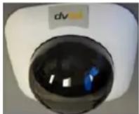 | CM-SMOKE-62 | Smoked bubble cover. Full F-stop darkening of camera interior. |
 | CM-4S-62 | 4S electrical box mounting adapter. Rotates camera position by 45° when mounting to a 4S electrical box. |
 | CM-F150-62 | 1-1/2" threaded quarter-turn adapter. |
 | CX-F125-0 | 1-1/4" inner threaded quarter-turn adapter. |
 | CX-F150-0 | 1-1/2" inner threaded quarter-turn adapter. |
FLIR Systems, Inc.
6769 Hollister Ave
Goleta, CA 93117
USA
PH: +1 805.964.9797
PH: +1 877.773.3547 (Sales)
PH: +1 888.747.3547 (Support)
FX: +1 805.685.2711
www.flir.com/security
Corporate Headquarters
FLIR Systems, Inc
27700 SW Parkway Ave.
Wilsonville, OR 97070
USA
PH: +1 503.498.3547
FX: +1 503.498.3153
- FLIR Systems, Inc.
- Important Instructions and Notices to the User:
- Proper Disposal of Electrical and Electronic Equipment (EEE)
- Document History
- Table of Contents
- List of Figures
- Document Scope and Purpose
- Note:
- Remarque:
- Avertissement:
- General Cautions and Warnings
- SAVE ALL SAFETY AND OPERATING INSTRUCTIONS FOR FUTURE USE.
- Caution:
- Attention:
- Overview
- Package Contents
- Related Documentation
- Introduction to the CM-620x Mini-Dome IP Camera
- Camera Dimensions
- Internal Connectors
- To perform a hard reset to full factory defaults using the Reset button
- Cable Connectors
- Input and Output Connectors
- Waterproofing the Camera Cable Connectors
- To waterproof the system cable
- To waterproof the RJ45 cable
- To waterproof the IP66-Rated RJ45 cable
- Connecting the Unit to the Network
- Connecting Power to the Camera
- System Requirements
- Installation
- Related Links
- Indoor Installation
- Outdoor Installation
- Initial Camera Configuration
- To perform the initial camera configuration
- Do the following:
- Tip:
- Preparing the Camera for Use
- To release the lens assembly for use
- Mounting Instructions
- To eliminate IR reflection
- Mounting the Camera
- Using the DNA Utility to Search and Access the Camera
- Configuring Communication Settings
- To configure communication settings on the camera
- Adjusting and Framing-Up the Camera View
- To adjust and frame-up the camera view
- Configuration and Operation
- Browser-Based Viewer Introduction
- - Live Button
- - Settings Button
- - System Settings
- - Streaming Settings
- - Camera Settings
- Live Screen
- To view the Live View window in Fullscreen mode
- To exit Fullscreen mode
- Full-Window Display
- Half-Window Display
- Full-Screen Mode
- Snapshot
- Record/Pause
- Video Streaming Restart/Stop
- Mic
- Manual Trigger
- Speaker
- Zoom: Wide/Tele
- Zoom Reset
- Step: Wide/Tele
- Step Range
- Focus: Near/Far
- Focus Reset
- Step: Near/Far
- AF: Push
- Enable Zoom Trigger
- System Tab
- System Settings
- System Screen
- Host Name
- Time Zone
- Enable Daylight Saving Time
- Time format
- Sync with Computer Time
- Manual
- Sync with NTP Server
- Security
- User
- Admin Password
- Add user
- To add a new user
- Manage User
- Streaming Authentication Setting
- HTTPS
- To create a self-signed certificate
- To create a certificate request
- IP Filter
- To enable the IP filter
- To add or delete an IP address
- IEEE 802.1X
- CA Certificate
- Client Certificate
- Private Key
- Settings
- Network
- Basic
- General
- Get IP address automatically
- Use fixed IP address
- To set up a new static IP address
- To use PPPoE
- Advanced
- IPv6 Address Configuration
- QoS
- DSCP Settings
- SNMP Settings
- SNMP v1/v2
- SNMP v3
- Traps for SNMP v1/v2/v3
- UPnP
- UPnP Settings
- DDNS
- To use DDNS
- FTP
- HTTP
- Events Setup
- IO
- Alarm Switch
- Alarm Type
- Alarm Output
- Trigger Action
- Follow these steps:
- File Name
- Network Failure Detection
- Detection Switch
- Detection Type
- Triggered Action
- Tampering
- Tampering Alarm
- Tampering Duration
- Tampering Action
- Day/Night Trigger
- To configure the day/night trigger
- Periodic Event
- Periodic Event
- Time Interval
- Manual Trigger
- SD Card
- Device Information
- Device Setting
- Disk Cleanup Setting
- Recording List
- Network Share
- Storage Tools
- Recording
- To set the recording schedule
- Motion Detection
- To activate Motion Detection
- To create a Motion Detection region
- To paint a motion detection region
- To set a schedule
- To configure motion detection settings
- Set Triggered Actions
- Schedule
- To create a new schedule or edit an existing schedule
- To remove a schedule
- File Location
- Maintenance
- Log File
- User Information
- View User Login Information
- View User Privilege
- Factory Default
- Full Restore
- Partial Restore
- Reboot
- Software Version
- Software Upgrade
- Warning:
- To upgrade the software
- Parameters
- To export a configuration file
- To import a configuration file
- Video Format
- CM-6204 Video Resolution Settings
- CM-6208 Video Resolution Settings
- Text Overlay Settings
- Video Rotate Type
- GOV Settings
- H.264 Profile
- • Baseline Profile (BP)
- - Main Profile (MP)
- • High Profile (HP)
- Video Compression
- MJPEG Compression Setting
- H.264 Compression Setting
- Quality
- Compression Information Setting
- CBR Mode Setting
- Video ROI Encoding
- To use ROI encoding
- Video OCX Protocol
- Video Frame Rate
- MJPEG/H.264 Frame Rate Setting
- Video Mask
- Active Mask Function
- To enable a mask
- To disable a mask
- Mask Setting
- Audio
- Transmission Mode
- Server Gain Setting
- Bit Rate
- Recording to Storage
- Camera Tab
- Exposure
- Exposure Mode
- Exposure Value (CM-6208 only)
- P-Iris Priority Mode
- Auto P-Iris Mode
- Manual Mode
- Picture Adjustment
- Brightness
- Sharpness
- Contrast
- Saturation
- Hue
- Advanced Picture Settings
- White Balance
- Backlight (CM-6208 only)
- WDR Function
- Shutter WDR (CM-6204 only)
- Noise Reduction
- 3DNR
- 2DNR
- ColorNR
- IR Function
- IR Mode
- IR LED Illuminator
- Day/Night Threshold
- IR Compensation
- Misc.
- Digital Zoom Settings
- TV System Settings
- Log Out
- Appendices
- A.3. Internet Security Settings
- To set the default Internet security level
- ActiveX Controls and Plug-in Settings
- To create a custom level
- A.4. Install UPnP Components
- To check that the UPnP Device Host services are running
- A.5. Installing and Deleting the Web Player
- To install the Quasar Player
- To delete an existing DVPlayer or DCViewer file
- To clear your computer's cache memory
- A.6. Deleting Temporary Internet Files
- To delete temporary Internet files
- A.7. Mounting Accessories
Brand : FLIR
Model : Quasar CM-6204
Category : Security Camera