
VC44ED-480 - Oven Vulcan - Free user manual and instructions
Find the device manual for free VC44ED-480 Vulcan in PDF.


| Product Type | Full Size Electric Convection Oven |
| Model | VC44ED-480 |
| Series | VC4E & VC6E Series |
| Dimensions (Cavity Depth) | 26.5 inches (67.3 cm) |
| Weight (Approx.) | 250 lbs (113 kg) |
| Power Supply | 480V, 3-Phase or 1-Phase, 60 Hz |
| Total Power | 12.5 kW |
| Amperage (3-Phase 480V per line) | 14.4 / 15.3 / 15.3 A (nominal) |
| Temperature Control | Solid State Temperature Control |
| Door Type | Independent Doors (50/50 split), stainless steel with window |
| Cook Timer | 1-Hour Dial or 5-Hour Dial (selectable) |
| Cook & Hold | Not available on this model (standard on computer control models) |
| Convection Fan | 2-speed (High/Low), motor with sealed bearings |
| Heating Elements | 6 elements (2.0 kW each), 480V |
| High Limit Thermostat | 550°F (288°C) auto-reset at 500°F (260°C) |
| Cooling Fan | Yes, for component cooling |
| Interior Lights | Two 40W incandescent lamps |
| Cleaning | Refer to instructions manual; use mild detergent, avoid abrasive cleaners |
| Safety Features | Door switch (interrupts operation when open), high limit thermostat |
| Spare Parts Availability | Available through Vulcan authorized service centers |
| Service | For trained Vulcan Service Technicians only; refer to service manual |
Frequently Asked Questions - VC44ED-480 Vulcan
User questions about VC44ED-480 Vulcan
0 question about this device. Answer the ones you know or ask your own.
Ask a new question about this device
Download the instructions for your Oven in PDF format for free! Find your manual VC44ED-480 - Vulcan and take your electronic device back in hand. On this page are published all the documents necessary for the use of your device. VC44ED-480 by Vulcan.
USER MANUAL VC44ED-480 Vulcan
natural_image
Exterior view of a stainless steel electric stove oven with dual doors and legs (no visible text or symbols)VC4ED SHOWN
VC4E & VC6E SERIES
FULL SIZE ELECTRIC CONVECTION OVENS
MODEL ML
VC4ES 126743
VC4ED 126744
VC4EC 126745
VC6ES 126746
VC6ED 126747
VC6EC 126748
- NOTICE -
This Manual is prepared for the use of trained Vulcan Service Technicians and should not be used by those not properly qualified. If you have attended a Vulcan Service School for this product, you may be qualified to perform all the procedures described in this manual.
This manual is not intended to be all encompassing. If you have not attended a Vulcan Service School for this product, you should read, in its entirety, the repair procedure you wish to perform to determine if you have the necessary tools, instruments and skills required to perform the procedure. Procedures for which you do not have the necessary tools, instruments and skills should be performed by a trained Vulcan Service Technician.
Reproduction or other use of this Manual, without the express written consent of Vulcan, is prohibited.
TABLE OF CONTENTS
GENERAL 4
Introduction 4
Installation 4
Operation 4
Cleaning 4
Lubrication 4
Tools 4
Specifications 5
REMOVAL AND REPLACEMENT OF PARTS ....
Covers and Panels 6
Control Panel Components 7
Component Panel Components 8
Temperature Probe (Solid State Control) 8
Heating Elements 9
Blower and Motor 10
Door Switch 11
Door Window 12
Oven Doors and Bearings (Independent Doors) 12
Oven Doors (Simultaneous Doors) 13
Roller Latch Assembly 14
Door Catch Roller Assembly (Independent Doors) 14
Mechanical (KX) Thermostat 15
High Limit Thermostat 15
Interior Lights 16
Cooling Fan 16
SERVICE PROCEDURES AND ADJUSTMENTS......
Solid State Temperature Control Calibration ....
Mechanical (KX) Thermostat Calibration 18
Solid State Temperature Control Test ....
Temperature Probe Test (Solid State Control) 20
Heating Element Test 20
Blower Adjustment 21
Door Adjustment 22
Door Strike Adjustment (Independent Doors) 22
Door Catch Roller Adjustment (Independent Doors) 23
Door Switch Adjustment 24
Door Chain Adjustment (Simultaneous Doors) 24
Computer Control 25
Computer Control Temperature Calibration ....
FULL SIZE ELECTRIC CONVECTION OVENS
Computer Control Operational Test 27
Component Location 30
Sequence of Operation 34
VC4ES, VC6ES with Mechanical KX Thermostat 34
VC4ED, VC6ED with Solid State Temperature Control ....
Timer Cycle, Cooking (KX Thermostat or Solid State Control)....
Cool Down Cycle (KX Thermostat or Solid State Control) ....
VC4EC, VC6EC (Computer Control) ......
Temperature and Time Cycle (Cooking) 36
Cook and Hold Cycle 36
Cool Down Cycle 36
Schematics 37
VC4ES, VC6ES with Mechanical (KX) Controls, 208-240V 37
VC4ES, VC6ES with Mechanical (KX) Controls, 480V 38
VC4ED, VC6ED with Solid State Temperature Control, 208-240V 39
VC4ED, VC6ED with Solid State Temperature Control, 480V 40
VC4EC, VC6EC Computer Control, 208-240V (Roast & Hold Standard) 41
VC4EC, VC6EC Computer Control, 480V (Roast & Hold Standard) 42
Wiring Diagrams 44
VC4ES, VC6ES with Mechanical (KX) Control, 208-240V 44
VC4ES, VC6ES with Mechanical (KX) Control, 480V 46
VC4ED, VC6ED with Solid State Temperature Control, 208-240V 48
VC4ED, VC6ED with Solid State Temperature Control, 480V 50
VC4EC, VC6EC Computer Control, 208-240V (Roast & Hold Standard) 52
VC4EC, VC6EC Computer Control, 480V (Roast & Hold Standard) 54
TROUBLESHOOTING 56
All Models 56
Computer Control Models Only 57
GENERAL
INTRODUCTION
Procedures in this manual will apply to all models unless specified. Pictures and illustrations can be of any model unless the picture or illustration needs to be model specific.
Models
| MODEL | FEATURES OPTIONS | |||||
| CAVITY DEPTH | TEMPERATURE CONTROL | DOORS (50/50) | COOK TIMER | COOK TIMER | COOK & HOLD | |
| VC4ES^4 | 26.5" Mechanical (KX) Independent ^1,2 | 1-Hour Dial 5-Hour Dial N/A | ||||
| VC4ED | 26.5" Solid State Independent ^1,3 | 1-Hour Dial 5-Hour Dial N/A | ||||
| VC4EC | 26.5" Computer Independent ^1,3 | 24-Hour Digital Built in Built in | ||||
| VC6ES^4 | 30.5" Mechanical (KX) Independent ^1,2 | 1-Hour Dial 5-Hour Dial N/A | ||||
| VC6ED | 30.5" Solid State Independent ^1,3 | 1-Hour Dial 5-Hour Dial N/A | ||||
| VC6EC | 30.5" Computer Independent ^1,3 | 24-Hour Digital Built in Built in | ||||
| NOTES: | 1. Simultaneous doors are optional (with or w/o window).2. Stainless steel doors w/o window (standard).3. Stainless steel doors with window (standard)4. In February 2001, this model was discontinued. | |||||
INSTALLATION
Refer to the Instructions Manual for detailed installation instructions on single or stacked ovens.
OPERATION
Refer to the Instructions Manual for specific operating instructions.
CLEANING
Refer to the Instructions Manual for specific cleaning instructions.
LUBRICATION
●Cavity blower motor has sealed bearings and requires no additional lubrication.
- Huskey's TF1000 grease or equivalent high temperature Teflon grease.
TOOLS
Standard
●Standard set of hand tools
●VOM with A.C. current tester (Any quality VOM with a sensitivity of at least 20,000 ohms per volt can be used)
●Gear Puller to remove blower
●Temperature tester (thermocouple type)
Special
- Manometer
- Clamp on amp meter
●Spring force gauge, pull type with a minimum 30 pound full scale range (purchase locally) - RTV sealant, 736 DOW silicone high temp (P/N 542133) or equivalent
SPECIFICATIONS
Electrical
| MODEL | TOTAL POWER (KW) | AMPERAGE - 3 PHASE/ 60HZ | |||||
| PER LINE ^1 | RECOMMENDED CIRCUIT PROTECTION ^2 | ||||||
| 208V | 240V | 480V | 208V | 240V | 480V | ||
| VC4ESVC4EDVC4ECVC6ESVC6EDVC6EC | 1 | 2 | . | 5 | 3 | 5 | |
| NOTES: | 1. Amperage values in the table are nominal. Tolerance is +5/-10%.2. Complied in accordance with National Electric Code, ANSI/NFPA 70, latest edition. | ||||||
1 5 4 5 4
| MODEL | TOTAL POWER (KW) | AMPERAGE - 1 PHASE/ 60HZ | |||||
| PER LINE ^1 | RECOMMENDED CIRCUIT PROTECTION ^2 | ||||||
| 208V | 240V | 480V | 208V | 240V | 480V | ||
| VC4ESVC4EDVC4ECVC6ESVC6EDVC6EC | 1 | 2 | . | 5 | 6 | 0 | |
| NOTES: | 1. Amperage values in the table are nominal. Tolerance is +5/-10%.2. Complied in accordance with National Electric Code, ANSI/NFPA 70, latest edition. | ||||||
2 6 8 0 7
REMOVAL AND REPLACEMENT OF PARTS
COVERS AND PANELS
⚠ WARNING Disconnect the electrical power to the machine and follow lockout / tagout procedures.
Top Front Cover
- The top front cover is secured with four (4) screws, two on each side of cover. Remove these screws then remove the cover from the oven.

- Reverse the procedure to install.
Bottom Front Cover
- The bottom front cover is secured with four (4) screws, two on each side of cover. Remove these screws then remove the cover from the oven.

- Reverse the procedure to install.
Control Panel
- Remove three (3) screws on the right side which secure the control panel then pull the panel away from the oven.
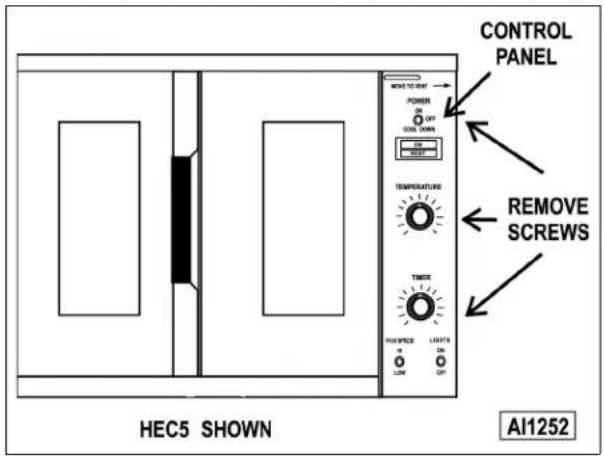
NOTE: If the oven has a mechanical (KX type) thermostat, it must be removed from the control panel first, before removing the control panel.
- Disconnect the temperature probe leads from the solid state temperature control.
- Unplug the wire harness connector to the control panel components.
- Reverse the procedure to install.
Right Side Panel
- Remove the two screws near front of oven, which secure the bottom front cover and control panel.
- Remove the remaining seven screws securing the right side panel.
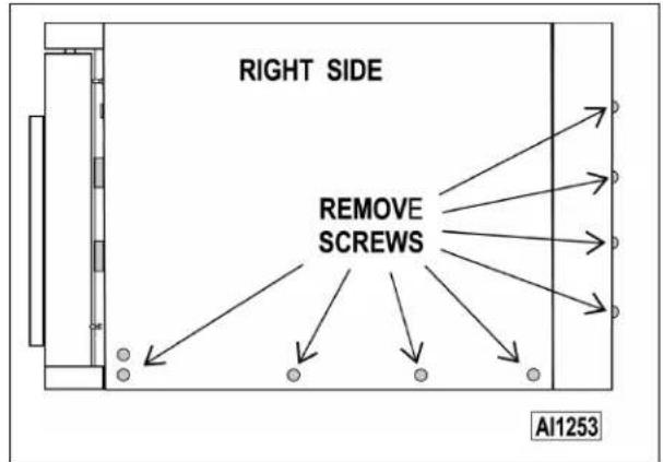
- Pull the right side panel out at the bottom then down to remove.
- Reverse the procedure to install.
Left Side Panel
- Remove the screws which secure the left side of the top front cover, bottom front cover and control panel.
- Remove the seven screws securing the left side panel.
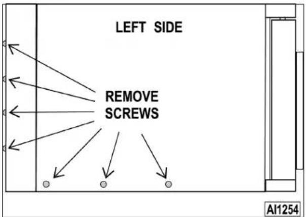
- Pull the left side panel out at the bottom then down to remove.
- Reverse the procedure to install.
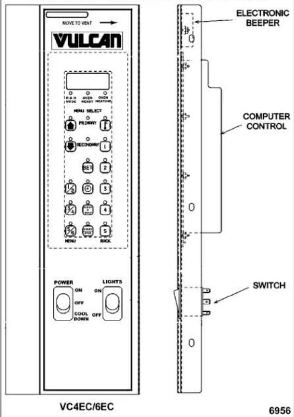
CONTROL PANEL COMPONENTS
WARNING Disconnect the electrical power to the machine and follow lockout / tagout procedures.
Removable Components
- Remove the control panel as outlined under COVERS AND PANELS.
- Remove the component being replaced.
- Reverse the procedure to install the replacement component, then check oven for proper operation.
PANEL WITH STANDARD CONTROLS SHOWN

PANEL WITH COMPUTER CONTROL SHOWN
COMPONENT PANEL COMPONENTS
WARNING Disconnect the electrical power to the machine and follow lockout / tagout procedures.
Removable Components
- Remove the right side panel as outlined under COVERS AND PANELS.
NOTE: If right side panel is not accessible, this component can be serviced by removing the control panel as outlined under COVERS AND PANELS. - Disconnect the wire leads to the component being replaced.
- Remove the component.
- Reverse the procedure to install the replacement component and check oven for proper operation.
COMPONENT PANEL - STANDARD OVEN CONTROLS (MECHANICAL OR SOLID STATE CONTROLS)

COMPONENT PANEL - COMPUTER CONTROL

TEMPERATURE PROBE (SOLID STATE CONTROL)

⚠ WARNING Disconnect the electrical power to the machine and follow lockout / tagout procedures.
- Remove the right side panel as outlined under COVERS AND PANELS.
NOTE: If right side panel is not accessible, this component can be serviced by removing the control panel as outlined under COVERS AND PANELS.
- Disconnect the probe leads from the solid state temperature control.
- Remove the racks and right rack support.
- Remove the probe guard or mounting clips.

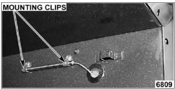
- Remove probe by pushing it through the oven wall and into the control panel area.
NOTE: The hole in the oven cavity wall does not line up straight with the oven cavity outer shell, therefore the probe must be removed at an angle.
-
Reverse the procedure to install the replacement probe.
-
Adjust the temperature control as outlined under SOLID STATE TEMPERATURE CONTROL CALIBRATION in SERVICE PROCEDURES AND ADJUSTMENTS.
HEATING ELEMENTS
WARNING Disconnect the electrical power to the machine and follow lockout / tagout procedures.
NOTE: Starting with production in October, 2001, the top cavity panel will have 3/4" square holes for easier element removal. Ovens manufactured prior to this date have 1/2" round holes that sometimes make it difficult to remove elements thru the cavity. A serial number cut off will not be available. Follow the procedures for element removal as outlined below.
Front Access
- Remove the oven racks and rack supports.
- Remove the "top" door seal from the oven.
- Determine if the heating element to replace is on the left or right side in the oven cavity. The element locations from front to back are: Right side - R1, R2 & R3; Left side - R4, R5 & R6.
A. Measure the current draw of the heating elements as outlined under HEATING ELEMENT TEST in SERVICE PROCEDURES AND ADJUSTMENTS.
- From inside the oven cavity, remove the perforated panel from the same side of the element being replaced.

A. If removing the right side panel, also remove the probe guard or mounting clips.
B. Run the probe wire thru the panel opening before lifting panel out.
- From the element being replaced, remove the hold down clamps, the mounting bracket screws at the top, then remove the element.
NOTE: The mounting bracket is sealed with RTV which may still hold the element after the screws are removed. Also, in some cases, the ring terminal connected to the element may interfere with easy removal. If access to the left side panel and/or the top panel is available, see ALTERNATE ACCESS.
- Disconnect the lead wires from the element.
- Clean RTV residue from the mating surface inside the oven, apply new high temperature RTV to the heating element mounting bracket and reverse procedure to install.
- Check for proper operation.
Alternate Access
If the heating element is not removing easily from inside the oven cavity, and access to the left side panel and/or the top panel is available, this alternate removal method may be used.
NOTE: On stacked ovens, if the bottom oven is being serviced and the heating element to replace is on the right side, the ovens must be unstacked to access the heating element terminals through the top. Once unstacked, follow the removal procedure below.
- Perform steps 1 thru 4 under FRONT ACCESS.
- If the element is on the left__ side:
A. Remove the left side panel and pull back the insulation at the top to expose the element terminals.
B. Remove the lead wires from the element being replaced. Proceed to step 4.
- If the element is on the right side:
A. Remove the top panel and pull back the insulation to expose the element terminals.
B. Remove the lead wires from the element being replaced.
- From the same element, remove the two clamps holding the element vertical, the screw's securing mounting bracket at the top, and then remove the element.
NOTE: The mounting bracket is sealed with RTV which may still hold the element after the screws are removed.
5. Clean RTV residue from the mating surface inside the oven, apply new high temperature RTV to the heating element mounting bracket and reverse procedure to install.
6. Check for proper operation.
BLOWER AND MOTOR

⚠ WARNING Disconnect the electrical power to the machine and follow lockout / tagout procedures.
- Take out the racks and rack supports.
- Remove screws securing baffle panel and remove the panel.

- If replacing:
A. Blower Only - Loosen set screws on blower hub and using a bearing puller, remove blower from motor shaft.
1) Reverse procedure to install and adjust blower position as outlined under BLOWER ADJUSTMENT in SERVICE PROCEDURES AND ADJUSTMENTS.
B. Motor - perform step 3A and continue procedure.
- Remove the nuts that secure the motor mounting plate to the rear wall.
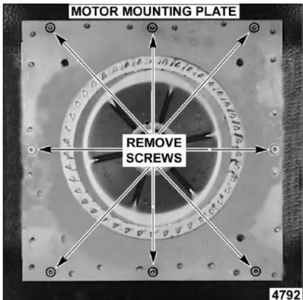
- Place a piece of cardboard on the bottom of the oven cavity to protect its surface from any damage during motor assembly removal.
- Pull the motor assembly into the oven cavity and place it on the cardboard.
- Remove the junction box cover from the motor, disconnect lead wires and remove the conduit.
- Remove motor mounting bolts and flat washers then lift the motor from the mounting plate.
- Position the replacement motor on the motor mounting plate and install mounting bolts and washers. Hand tighten mounting bolts only.
INSTALL BOLT, WASHER & NUT AS SHOWN
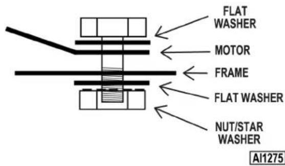
- Reconnect lead wires at the motor, replace conduit and junction box cover.
NOTE: Check data plate on motor for wiring schematic. The motor must rotate clockwise when viewed from the shaft end.

- Slide blower onto motor shaft until hub is flush with end of shaft then tighten set screws.
- Adjust motor position until blower is parallel to motor mounting plate as outlined under BLOWER ADJUSTMENT in SERVICE PROCEDURES AND ADJUSTMENTS.
- Position motor mounting plate on the rear wall and secure with nuts and washers.
- Replace the baffle panel.
- Remove cardboard from the bottom of the oven cavity.
- Check oven for proper operation then replace rack guides and racks.
DOOR SWITCH

WARNING Disconnect the electrical power to the machine and follow lockout / tagout procedures.
- Remove the top front cover as outlined under COVERS AND PANELS.
- Disconnect the lead wires to the door switch.
- Remove the switch.

- Reverse procedure to install the replacement switch and check for proper adjustment as outlined under DOOR SWITCH ADJUSTMENT in SERVICE PROCEDURES AND ADJUSTMENTS.
DOOR WINDOW

WARNING Disconnect the electrical power to the machine and follow lockout / tagout procedures.
- Remove the screws at the top and bottom of door.

- Independent doors:
A. Remove the door handle then remove the outer door panel.
B. Lift out the inner door panel and window assembly.
NOTE: Left door only - remove door seal from the inside edge of the door.
- Simultaneous doors:
A. If replacing window on the left door, remove the handle from the front of the door then remove door seal from the inside edge of the door.
1) Lift out the inner door panel and window assembly.
2) If replacing window on the right door, remove the screws along the inside edge (if applicable) of the door then remove the inner door panel and window assembly.
- Remove the screws securing the window "tabs" to the door bracket and lift the window assembly out from the door frame.
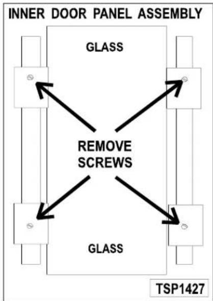
flowchart
graph TD
    A["INNER DOOR PANEL ASSEMBLY"] --> B["GLASS"]
    B --> C["REMOVE SCREWS"]
    C --> D["GLASS"]
    D --> E["TSP1427"]
- Reverse procedure to install the replacement window.
OVEN DOORS AND BEARINGS (INDEPENDENT DOORS)

WARNING Disconnect the electrical power to the machine and follow lockout / tagout procedures.
- Remove the top front cover and bottom front cover as outlined under COVERS AND PANELS.
- Remove the door switch lever.
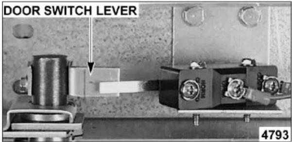
- Remove the lower door seal strip to expose the mounting screws of the door assembly.
- Remove the two (2) lower sill bolts by the lower door shaft and the four (4) counter-sunk screws from the lower sill.

NOTE: The door assembly is heavy and will drop down once the last screw is removed. If removing door assembly with-out assistance, use caution.
- Tilt the top of the door slightly forward and lift the door up until the bottom of the door shaft clears the opening in the sill.
- Lay the door flat to prevent damage.
- The top and bottom bearings are now accessible for inspection and/or replacement if needed.
A. If bearings are ok, proceed to step 8.
B. If replacing the top bearing, remove the top bearing retainer and top bearing.

C. If replacing the bottom bearing, remove it from the door shaft or the lower sill opening.
- Reverse procedure to install door assembly and check for proper adjustment as outlined under DOOR ADJUSTMENT and DOOR SWITCH ADJUSTMENT in SERVICE PROCEDURES AND ADJUSTMENTS.
OVEN DOORS (SIMULTANEOUS DOORS)

⚠ WARNING Disconnect the electrical power to the machine and follow lockout / tagout procedures.
Assembly Removal
- Remove the top front cover and bottom front cover as outlined under COVERS AND PANELS.
- Remove the door switch lever.
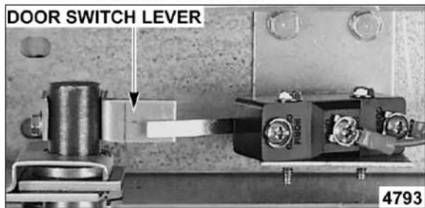
- Remove the top bearing retainers and top bearings.

- Remove the lower door seal strip to expose the mounting screws of the door assembly.
A. Remove the two (2) lower sill bolts by the lower door shaft and the four (4) counter-sunk screws from the lower sill.

NOTE: The door assembly is heavy and will drop down once the last screw is removed. If removing door assembly with-out assistance, use caution.
- Lift up on the door assembly and swing the right side out then move the assembly to the left to clear the slots in the upper door sill.
- Lay the door assembly on a flat cushioned surface for disassembly.
- Reverse procedure to install door assembly and check for proper adjustment as outlined under DOOR ADJUSTMENT, DOOR CHAIN ADJUSTMENT (SIMULTANEOUS DOORS) and DOOR SWITCH ADJUSTMENT in SERVICE PROCEDURES AND ADJUSTMENTS.
Disassembly
- Remove the door assembly as outlined in OVEN DOORS (SIMULTANEOUS) under ASSEMBLY REMOVAL.
- Remove the door chain by loosening one of the turnbuckles.
- Loosen the set screw on the sprocket of door being replaced.
- Drive out the spirol pin from the sprocket of door being replaced.
- Remove the door from lower sill bearings and sprocket.

A. Door assembly parts are now accessible for inspection and/or replacement if necessary.
- Reverse procedure to re-assemble the door assembly parts and check for proper adjustment as outlined under DOOR CHAIN ADJUSTMENT (SIMULTANEOUS DOORS) in SERVICE PROCEDURES AND ADJUSTMENTS.
ROLLER LATCH ASSEMBLY (INDEPENDENT DOORS)
NOTE: For units with serial number starting with 48 made after 8/12/07 and serial number starting with 54 made after 8/26/07.
⚠ WARNING Disconnect the electrical power to the machine and follow lockout / tagout procedures.
- Remove the screws that attach roller latch assembly to door.
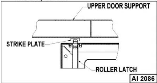
- Reverse procedure to install.
DOOR CATCH ROLLER ASSEMBLY (INDEPENDENT DOORS)
NOTE: For units with serial number starting with 48 made before 8/13/07 and serial number starting with 54 made before 8/27/07.

⚠ WARNING Disconnect the electrical power to the machine and follow lockout / tagout procedures.
- Remove the top front cover as outlined under COVERS AND PANELS.
- Remove the catch roller assembly.
FRONT VIEW
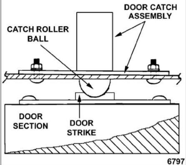
- Reverse procedure to install.
- Adjust the catch roller as outlined under DOOR CATCH (ROLLER) ADJUSTMENT (INDEPENDENT DOORS) in SERVICE PROCEDURES AND ADJUSTMENTS.
MECHANICAL (KX) THERMOSTAT

WARNING Disconnect the electrical power to the machine and follow lockout / tagout procedures.
- Remove the racks and right rack support.
- Remove the thermostat knob and mounting screws from the control panel and then remove the control panel.
- Remove the probe guard from the oven cavity wall.
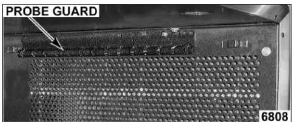
NOTE: When installing probe guard, the probe should not extend beyond the guard.
- Remove the thermostat bulb from the oven cavity by pushing it through the oven wall and into the control panel area.
NOTE: The hole in the oven cavity wall does not line up straight with the oven cavity outer shell, therefore the probe must be removed at an angle.
- Reverse the procedure to install.
- Adjust the thermostat as outlined under MECHANICAL (KX) THERMOSTAT CALIBRATION in SERVICE PROCEDURES AND ADJUSTMENTS.
HIGH LIMIT THERMOSTAT

WARNING Disconnect the electrical power to the machine and follow lockout / tagout procedures.
- Take out racks from the oven.
- Remove the high limit thermostat cover/mounting plate from inside the oven cavity at the top.

- Disconnect lead wires from high limit thermostat then remove high limit thermostat from cover/mounting plate.

NOTE: Remove the old RTV sealer from the cover and mating surfaces inside the oven cavity and apply new high temperature RTV sealer before installing.
- Reverse procedure to install.
INTERIOR LIGHTS
⚠ WARNING Disconnect the electrical power to the machine and follow lockout / tagout procedures.
Lamp
- Remove the racks.
- Unscrew the glass lens for the light being replaced then unscrew the bulb.

- Replace bulb then reverse the procedure to install.
Lamp Assembly
- Remove the lens and bulb.
- Remove the springs from the retaining tabs (2 places) on the socket.

- Depress the retaining tabs and pull the socket out from the oven, far enough to disconnect the lead wires.
- Remove the socket from the oven.
- Attach the lead wires to the replacement socket.
- Insert the socket into the hole in the oven and push until the socket is held in place by the retaining tabs.
- Install the light bulb and lens.
F25105 (Rev. A, October 2007) Page 16 of 60
- Check for proper operation.
COOLING FAN

⚠ WARNING Disconnect the electrical power to the machine and follow lockout / tagout procedures.
- Remove the right side panel as outlined under COVERS AND PANELS.
NOTE: If right side panel is not accessible, this component can be serviced by removing the control panel as outlined under COVERS AND PANELS.
- Disconnect the lead wires to the fan motor by removing wire nuts.
- Remove the screws securing the air deflector to the fan then loosen the tab screw holding the fan to the component panel. Rotate the tab so that the fan will clear and remove the fan.
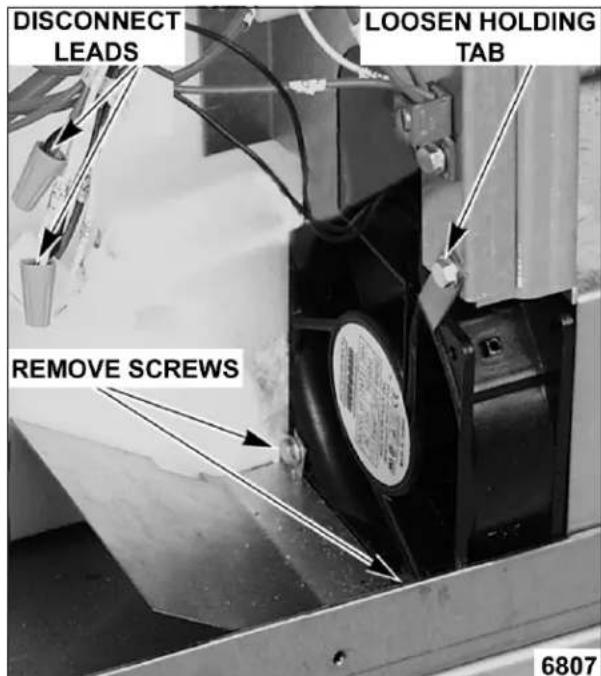
- Reverse the procedure to install the replacement fan and check for proper operation.
NOTE: The fan must be installed so air is pulled from outside the rear of the oven and blown into the control area. The arrow on the fan body indicates "air flow" direction and should be pointing toward the controls.
NOTE: Ensure fan is seated "squarely" against the air tube and the oven bottom.
NOTE: The air deflector should be angled upwards at approximately 30 degrees to properly direct the air flow.
SERVICE PROCEDURES AND ADJUSTMENTS
⚠ WARNING Certain procedures in this section require electrical test or measurements while power is applied to the machine. Exercise extreme caution at all times. If test points are not easily accessible, disconnect power and follow lockout / tagout procedures, attach test equipment and reapply power to test.
SOLID STATE TEMPERATURE CONTROL CALIBRATION
- Place a thermocouple in the geometric center of the oven cavity.
- Set the power switch to ON.
- Set the temperature control dial to 350^ F.
- Allow the oven temperature to stabilize (normally 3 cycles).
- Record the temperature at which the Heat lamp goes OFF and comes ON for at least two complete heating cycles.
- Calculate the differential by subtracting the temperature indicated when the lamp goes out from the temperature indicated when the lamp comes on.
Differential = Heat lamp OFF - Heat lamp ON Example: 360° (lamp off) - 340° (lamp on) = 20°
A. The differential calculated should be less than 20^ F.
1) If the differential is 20^ F or less, the temperature control circuit is functioning properly.
a. Proceed to step 7.
2) If the differential is more than 20^ F:
a. Check the temperature probe as outlined under "TEMPERATURE PROBE TEST (SOLID STATE CONTROL)".
b. If the probe is functioning properly then temperature control is malfunctioning.
a) Install a replacement temperature control and check calibration.
- Calculate the average temperature by adding the temperature indicated when the lamp goes out to the temperature indicated when the lamp comes on and dividing this answer by 2.
[Temp. (lamp off) + Temp. (lamp on)] + 2 = Average Temp. Example: 360^ + 340^ ÷ 2 = 350^
A. If the average temperature is 10^ F or less, from the dial setting, the thermostat is properly calibrated.
B. If the average temperature is more than 10 °F from the dial setting, the thermostat calibration must be adjusted.
1) Loosen the temperature control knob set screw and remove the knob from the stem.
2) Loosen temperature control mounting screws only enough to rotate the control.
a. Place thumb and forefinger on the head of the mounting screws, apply pressure and slightly rotate the screw heads (body of control) in the slot. Rotate clockwise to increase temperature and counterclockwise to decrease.
b. Center the stem in the opening and re-tighten the temperature control mounting screws.
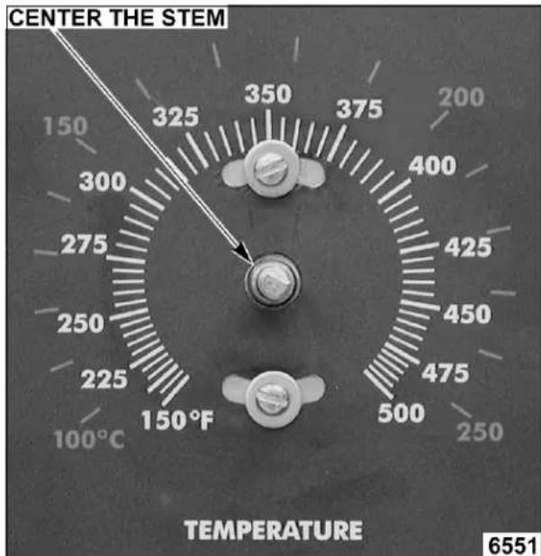
c. Replace knob and re-tighten set screw.
d. Rotate the knob to the lowest temperature setting then back to 350^ F.
e. Repeat the average temperature calculation in step 7.
NOTE: Allow the oven to cycle at least two times between adjustments before performing the calculation.
a) If the average temperature still differs more than 10 °F from the dial setting, adjust the thermostat calibration until the average temperature is within tolerance.
C. If the above adjustment cannot be obtained:
1) Turn the power switch OFF.

⚠ WARNING Disconnect the electrical power to the machine and follow lockout / tagout procedures.
2) Replace the temperature control and check calibration.
MECHANICAL (KX) THERMOSTAT CALIBRATION
-
Place a thermocouple in the geometric center of the oven cavity.
-
Set the power switch to ON.
-
Set the thermostat dial to 350^ F.
-
Allow the oven temperature to stabilize (normally 3 cycles).
-
Record the temperature when the thermostat cycles OFF and ON for at least three complete cycles.
-
Calculate the differential by subtracting the temperature indicated when heat lamp goes out from temperature indicated when heat lamp comes on.
Differential = Heat lamp OFF - Heat lamp ON Example: 360° (lamp off) - 340° (lamp on) = 20°
A. The differential calculated should be less than 30^ F.
1) If the differential is 30^ F or less ____, the thermostat is functioning properly. a. Proceed to step 7.
2) If the differential is more than 30 °F, the thermostat is malfunctioning. a. Install a replacement thermostat and check calibration.
- Calculate the average temperature by adding the temperature indicated when the heat lamp goes out to the temperature indicated when the heat lamp comes on and dividing this answer by 2.
[Temp. (lamp off) + Temp. (lamp on)] + 2 = Average Temp. Example: 360^ + 340^ + 2 = 350^
A. If the average temperature is 15^ F or less from the dial setting, the thermostat is properly calibrated.
B. If the average temperature is more than 15 °F of the dial setting, the thermostat calibration must be adjusted.
1) Remove the thermostat knob.
2) Hold the thermostat shaft and turn the inner set screw clockwise to decrease temperature or counterclockwise to increase temperature ( 14 turn = 35°F).

- Replace the knob and verify the setting is still at 350^ F.
- Repeat step 7 until the average temperature is within tolerance.
NOTE: Allow the oven to cycle at least two times between adjustments before performing the calculation.
A. After the final adjustment is made and the average temperature is within tolerance, remove the knob and apply a non-permanent type sealer around the head of the set screw.
- If the above adjustment cannot be obtained:
A. Turn the power switch OFF.

WARNING Disconnect the electrical power to the machine and follow lockout / tagout procedures.
B. Install a replacement thermostat and check calibration.
SOLID STATE TEMPERATURE CONTROL TEST
- Remove the right side panel as outlined under COVERS AND PANELS in REMOVAL AND REPLACEMENT OF PARTS.
NOTE: If right side panel is not accessible, this component can be serviced by removing the control panel as outlined under COVERS AND PANELS.
- Place a thermocouple in the geometric center of the oven cavity.
NOTE: Oven temperature must be below 450°.
-
Set the temperature control to the maximum setting.
-
Check machine data plate for correct voltage to oven. Refer to diagram below for proper terminal locations and voltages before checking the control. Use the correct terminals for the corresponding voltage.
-
Turn the power switch to ON.
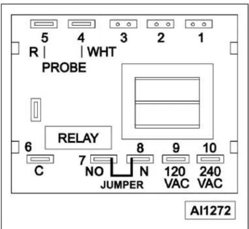
- Check for proper voltage across terminals 8 & 10 (208-240VAC) for power to the control.
A. If correct, proceed to step 7.
B. If incorrect, problem is not_ with the temperature control. See TROUBLESHOOTING.
- Check relay voltages on the board:
A. For 208-240VAC controls - check across terminals 7 & 10 for input to the internal relay and 6 & 10 for output from the internal relay.
1) If input voltage to the internal relay is correct, proceed to step 8. If input voltage to the internal relay is not present, problem is not with the temperature control. See TROUBLESHOOTING.
2) If output voltage from the internal relay is correct proceed to step 8. If output voltage from the internal relay is not correct, check temperature probe as outlined under TEMPERATURE PROBE TEST (SOLID STATE CONTROL).
- Set the temperature control to the minimum setting.
NOTE: Oven temperature must be above 300°F.
- Check for zero (0) volts AC across terminals 6 & 10 (208-240VAC) for no output from the internal relay.
A. If correct, temperature control is functioning properly.
B. If incorrect, check temperature probe as outlined under TEMPERATURE PROBE TEST (SOLID STATE CONTROL).
1) If temperature probe is ok:
a. Turn the power switch OFF.

⚠ WARNING Disconnect the electrical power to the machine and follow lockout / tagout procedures.
b. Replace the temperature control and check calibration as outlined under SOLID STATE TEMPERATURE CONTROL CALIBRATION.
TEMPERATURE PROBE TEST (SOLID STATE CONTROL)

WARNING Disconnect the electrical power to the machine and follow lockout / tagout procedures.
NOTE: The temperature probe used in conjunction with the Solid State Temperature control is an RTD (resistance temperature detector) of the Thermistor type. As temperature increases the resistance value decreases.
- Remove the right side panel as outlined under COVERS AND PANELS in REMOVAL AND REPLACEMENT OF PARTS.
NOTE: If right side panel is not accessible, this component can be serviced by removing the control panel as outlined under COVERS AND PANELS.
-
Place a shielded thermocouple in the geometric center of the oven cavity and determine the temperature in the oven cavity.
-
Remove the probe lead wires from the solid state temperature control.
-
Test the probe with an ohmmeter.
A. If the measured resistance values are inside the given tolerance then the probe is functioning properly.
B. If the measured resistance values are outside the given tolerance then replace the probe and retest.
1) Check oven for proper operation.
- Reverse procedure to install.
| TEMP (°F) | OHMS* TEM | P (°F) OHMS* | |
| 77 90,000 | 360 822 | ||
| 240 4,077 | 380 656 | ||
| 260 3,016 | 400 529 | ||
| 280 2,266 | 425 424 | ||
| 300 1,726 | 450 334 | ||
| 320 1,332 | 475 266 | ||
| 340 1,041 | |||
| (*) Resistance in ohms ± 10% | |||
HEATING ELEMENT TEST
⚠ WARNING The following steps require power to be applied to the unit during the test. Use extreme caution at all times.
-
Turn the power switch ON and set the oven temperature control to the highest setting.
-
Measure the voltage at the heating element terminals and verify it against the data plate voltage.
A. If voltage is incorrect, find the source of the problem.
B. If voltage is correct, check current draw (amps) through the heating element lead wires.
NOTE: This method is preferred over a resistance check when a clamp on type amp meter is available.
1) If current draw is correct then heating element is functioning properly. See table below for proper values.
2) If current draw is not correct, turn the power switch OFF and disconnect the electrical supply to the oven.
a. Replace heating element then proceed to step 3.
C. If unable to check current draw, a resistance check may indicate a malfunctioning element.
1) Turn the power switch OFF and disconnect the electrical supply to the oven.
2) Remove the lead wires from the heating element and check resistance (ohms). See table below for proper values.
- Check for proper operation.
| VOLTAGE | KW PER ELEMENT | AMPS PER ELEMENT LEAD | OHMS PER ELEMENT | |
| 1 PH | 3 PH | |||
| 208 | 2 | 6 | 0 | 3 |
| 240 | 2 | 5 | 2 | 3 |
| 480 | 2 | 15 | 4 | 111 |
| NOTES: | Values in the table are nominal.Tolerance is +5/-10%.Voltage values are @ 60HZ.Resistance values (ohms) are @ room temperature. | |||
BLOWER ADJUSTMENT
⚠ WARNING Disconnect the electrical power to the machine and follow lockout / tagout procedures.
-
Remove the blower motor and mounting assembly by following steps 1 through 7 as outlined under BLOWER AND MOTOR in REMOVAL AND REPLACEMENT OF PARTS.
-
Loosen the motor mounting bolts.
-
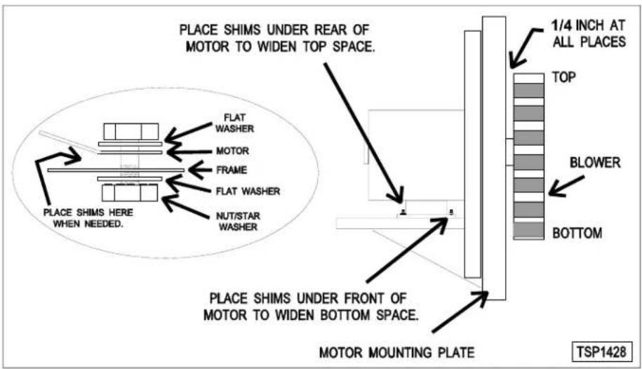
Adjust the motor position until the blower is parallel to and 1/4 inch away from the motor mounting plate. Check for squareness of the blower to the motor mounting plate at the top, bottom, left and right of the blower.
A. If the blower is square then tighten motor mounting bolts and proceed to step 4.
B. If the blower is not square continue adjusting until proper spacing is achieved then tighten motor mounting bolts.
NOTE: If necessary, place shims between motor and frame.
- Reverse the procedure to install.
DOOR ADJUSTMENT
- Check the doors to make sure they have an equal gap between them and that the vertical edge of the door is parallel to the vertical door seal. If the doors are not positioned in this manner, adjust the doors as described.

- Remove the top front cover.
- Loosen the screws that secure the upper door bearings and related hardware, just enough to allow door movement.

- Move the door until proper alignment is achieved then tighten the screws on the upper door bearing hardware.
- Repeat step 3 and 4 on the opposite door, if necessary.
DOOR STRIKE ADJUSTMENT (INDEPENDENT DOORS)
NOTE: For units with serial number starting with 48 made after 8/12/07 and serial number starting with 54 made after 8/26/07.

WARNING Disconnect the electrical power to the machine and follow lockout / tagout procedures.
- Remove top front cover as outline under COVERS AND PANELS in REMOVAL AND REPLACEMENT OF PARTS.
- Open the doors and inspect door strike for proper shape.
A. Replace if bent. Do not bend strike plate.
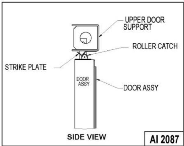
B. If adjustment is necessary, loosen fasteners, close doors and insure contact between door inner surface and upper horizontal seal. Slide door strike plate until contact with roller latch is made. Tighten strike plate fasteners
- Open and close the doors several times while observing the roller latch and strike plate operation.
A. Replace roller latch if malfunctioning as outlined under ROLLER LATCH ASSEMBLY (INDEPENDENT DOORS) and adjust as outlined in this procedure.
- Each oven door should open with a force of 8 to 25 pounds when pulled at the handle. The adjustments must allow the doors to remain closed during normal operation and allow opening without exertion by the user.
DOOR CATCH ROLLER ADJUSTMENT
(INDEPENDENT DOORS)
NOTE: For units with serial number starting with 48 made before 8/13/07 and serial number starting with 54 made before 8/27/07.

WARNING Disconnect the electrical power to the machine and follow lockout / tagout procedures.
- Remove the top front cover as outline under COVERS AND PANELS in REMOVAL AND REPLACEMENT OF PARTS.
- Open the doors and inspect the door strike for proper shape.

A. Replace if bent and adjust as outlined in this procedure.
- Open and close the doors several times while observing the catch roller operation.
A. Replace if malfunctioning and adjust as outlined in this procedure.
NOTE: Shims may be required under the door strike to raise it, before the proper door tension adjustment can be set.
-
Apply lubricant around the spring. See LUBRICATION under GENERAL.
-
Close the doors and check them for proper alignment.
A. Doors should be centered and parallel at the top and bottom, in the oven cavity opening. See DOOR ADJUSTMENT.
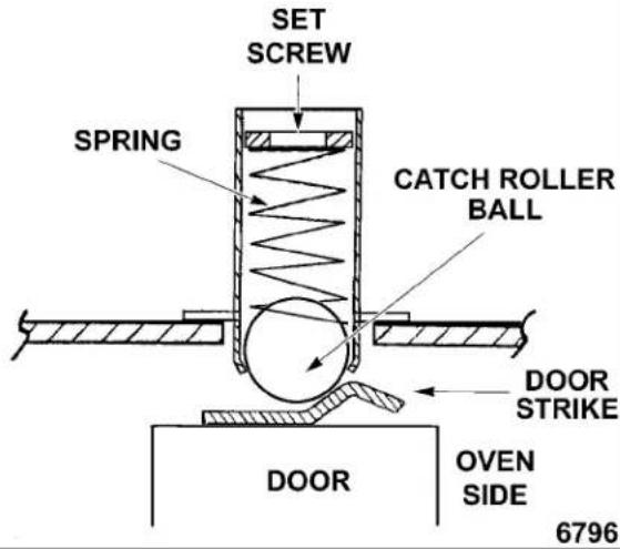
- With the doors closed, observe the position of the catch roller "ball" in relation to the door strike.
A. Ensure the catch roller "ball" is centered (left to right) to the door strike.
1) Adjust alignment, if necessary.
B. Open the right side door and view the left side door catch roller and strike. Ensure the door catch roller "ball" is resting upon the angular surface of the door strike. Repeat on the opposite door.
1) If adjustment is necessary, loosen the mounting screws then slide the door strike from "front to back" until the roller rests upon the angular surface of the door strike. Tighten screws and check operation.
2) If proper adjustment cannot be achieved, add shims beneath the door strike. Repeat step 6 thru this step. DO NOT BEND THE DOOR STRIKE.
- Each oven door should open with a force of 8 to 25 pounds when pulled at the handle. See TOOLS under GENERAL.
A. Adjust catch roller tension as follows:
1) Turn the set screw inside the catch assembly housing clockwise to increase tension on the catch roller and counterclockwise to decrease tension on the catch roller.
NOTE: The amount of tension on the catch roller determines the opening force of the door.
2) Continue adjustment until proper door operation is achieved.
SIDE VIEW CUTAWAY
DOOR SWITCH ADJUSTMENT

WARNING Disconnect the electrical power to the machine and follow lockout / tagout procedures.
-
Remove the top front cover as outlined under COVERS AND PANELS in REMOVAL AND REPLACEMENT OF PARTS.
-
Door operation:
A. Independent doors - The switch actuator should be operated by the switch lever when the right door is between 1" and 1 1/2" from being closed.
B. Simultaneous doors - The switch actuator should be operated by the switch lever when the right door is 1/2" from being closed.
- If adjustment is necessary, bend the switch actuator to obtain the proper setting.

- Install the top front cover.
- Apply power to the oven and check for proper operation.
DOOR CHAIN ADJUSTMENT (SIMULTANEOUS DOORS)
Introduction
When the oven doors are in proper adjustment, as the doors come together, the right door will lead the left door in closing by about 1/4 inch. The doors will feel like they are self closing the last 1/2 inch of travel.
Procedure
- Remove the lower sill cover as outline under COVERS AND PANELS in REMOVAL AND REPLACEMENT OF PARTS.
- Close doors and check door chain for factory setting.
A. Turnbuckles should be 5 to 5 1/2 inches apart.
B. Short eye bolt should be connected to the end of the chain that goes to the front of the sprocket.
C. 2 links of the chain should not be engaged at the rear of the sprocket.
D. Chain must be tight enough that the doors move simultaneously when opened or closed.
E. When the doors are opened, the turnbuckles will move away from each other.
F. The stop cable must be positioned where it moves freely and does not get pinched.
- Position door chain assembly to factory setting if the conditions in step 2 are not met.

CROSS SECTION OF SPROCKET AND CHAIN

- If right door does not lead the left door in closing:
A. Loosen locknuts on both turnbuckles.
B. Loosen left turnbuckle.
C. Tighten right turnbuckle.
D. Tighten locknuts on both turnbuckles.
- If the right door leads the left door by more than 3/8 inch:
A. Loosen locknuts on both turnbuckles.
B. Loosen right turnbuckle.
C. Tighten left turnbuckle.
D. Tighten locknuts on both turnbuckles.
- Check door for proper operation.
NOTE: The locknuts must be tight during testing or the adjustment will not hold.
A. If doors do not close properly, repeat step 4, 5 and 6.
B. If doors operate properly, continue to step 7.
- Install the lower front cover.
COMPUTER CONTROL
Operation
Refer to the Instructions Manual for specific operating instructions.
Setup Mode
NOTE: Use the setup mode to verify that the control is configured to the factory settings which result in the proper operation of the oven. If the CAL1 parameter is other than zero, determine if it is still needed before resetting to zero. See COMPUTER CONTROL TEMPERATURE CALIBRATION.
NOTICE Changing the C_F, InP1, rL1 & rH1 parameters will default all menus to the factory settings.
- Use this key sequence to access the setup mode.
Up arrow; Rack 1; Temperature; Temperature; Down arrow; Rack 1


TSP1503C
-
Once in the setup mode the display will alternate between the parameter and programmed data.
-
To change data to the factory setting, use the arrow keys.
-
To select the next parameter, press the Rack 1 key.
-
After the last Parameter and Data is viewed, press the Rack 1 key a final time to exit the setup mode and return to operations mode. The current set point temperature will be displayed.
• After 1 minute of no key activations, the control will return to operation mode. -
Listed are the parameters and data you should find.
| MENU | ALTERNATING ON DISPLAY | |
| PARAMETER DATA | ||
| Celsius_Fahrenheit C_ | F F | |
| Guard Band gb 4000 | ||
| Temperature Compensation | tcnP OFF | |
| Input Type 1 InP1 J | ||
| Range Low 1 rL1 75 | ||
| Range High 1 rH1 500 | ||
| Hysteresis HYS1 | 3 | |
| Calibration Offset | CAL1 | 0 |
| Exit Setup Mode and return to Operation Mode. | set point temperature is displayed or if call for heat, dashes (----) displayed. | |
Probe Test
If the oven is not heating or displaying the proper temperature, the temperature probe may be malfunctioning. Determine if the probe is good or causing the operational problem. Temporarily, disconnect the existing probe lead wires from the computer control and connect the lead wires from a known good "J" type thermocouple. Secure the sensing end of the thermocouple near the probe.
Turn the power switch ON and set the dial to 350^ F.
If the oven reaches the set temperature and cycles with the temporary thermocouple, then the existing probe is malfunctioning. Replace temperature probe with the correct part and check for proper operation.
Solid State Relay Test
The solid state relays "SSR1 or SSR2" supply power to the blower motor "high" or "low" fan speed terminals when the SSR is energized by the output voltage from the computer.
To test solid state relay "SSR1" (high fan speed), the computer control should be in the "Normal Cooking Mode". To test solid state relay "SSR2" (low fan speed), the computer control should be in the "Cook & Hold Mode".

-
Remove the right side panel as outlined under COVERS AND PANELS.
-
Turn the power switch ON.
A. If the blower motor comes on, the SSR is functioning properly.
B. If the blower motor does not come on, proceed to step 3.
- Check for +5 VDC on the input side of SSR (terminals 3 & 4).
A. If +5 VDC is present, continue to step 4.
B. If no voltage is present, computer control is not functioning properly.
- Check for proper input voltage on the load side of SSR terminal 1 and the power connection on the other side of the supply.
A. On 208 & 240 volt ovens, the supply connection is on the terminal block (L2 for single phase, L3 for three phase).
The measured voltage should be identical to the supply.
B. On 480 volt ovens, the supply connection is on the secondary side of the 480V transformer, terminal X4 (wire # 79).
The measured voltage should be 240 volts.
- If input voltage is correct on the load side of SSR terminal 1, proceed to step 6.
A. If input voltage is not correct, find the source of the problem.
- Check output voltage on the load side of SSR terminal 2.
A. If voltage is correct, SSR is functioning properly.
B. If no voltage is present on the load side of SSR terminal 2, the SSR is not functioning properly.
- Turn the power switch OFF.

WARNING Disconnect the electrical power to the machine and follow lockout / tagout procedures.
- Replace the SSR and check for proper operation.
COMPUTER CONTROL TEMPERATURE CALIBRATION
- Place a thermocouple in the geometric center of the oven cavity.
- Turn the power switch ON.
A. If the set point temperature is 350^ F, proceed to step 4.
B. If the set point temperature is other than 350^ F, proceed to step 3 to change the temperature.
- Press the set key then temperature key to enter the temperature set mode.
A. The display will alternate between the term "StPt" (set point) and the current oven temperature setting.
B. Press the up or down arrow keys to make the proper selection.
C. Press the set key again to save the change and exit the temperature set mode.
- Allow the oven temperature to stabilize (normally 3 cycles).
- Compare the controls set point temperature to the thermocouple meter reading when the heat light goes out.
A. A temperature variance more than 5^ F indicates an adjustment is needed.
1) To make the adjustment, proceed to step 6.
2) If temperature variance is less than 5^ F , computer control is functioning properly.
- Enter the setup mode as outlined in SETUP MODE under COMPUTER CONTROL.
A. Advance through the menu until CAL1 (Calibration Offset) appears.
1) If the thermocouple reading is higher than set point temperature, press the down arrow key and enter a negative offset value that is equal to the number of degrees above the 5^ F tolerance.
2) If the thermocouple reading is lower than set point temperature, press the up arrow key and enter a positive offset value that is equal to the number of degrees below the 5^ F tolerance.
3) Exit the setup mode.
- Allow the oven to cycle at least two times between adjustments.
A. If the temperature variance still differs more than 5^ F from the set point, verify the correct calibration offset value was entered and retained.
1) Adjust the calibration offset value as outlined in step 6, until the cycling temperature is within tolerance.
B. If the above adjustment cannot be obtained:
C. Turn the power switch OFF.

WARNING Disconnect the electrical power to the machine and follow lockout / tagout procedures.
D. Replace the computer control and check for proper operation.
COMPUTER CONTROL OPERATIONAL TEST
The computer controls "Calibration Mode" is used to manually test:
- Outputs of the control
- Keypad functionality
- Verify display and LEDs functionality
Additionally, if a problem is encountered during the output test, a "Restore Factory Settings" option is available.
NOTICE The calibration mode contains several adjustable parameters that must not be changed. For the "CALY" (Calibration) Parameter, the default data option selected must be "no".
Listed below are the parameters and data you should find in the calibration Mode.
| MENU | ALTERNATING ON DISPLAY | |
| PARAMETER | DATA | |
| Calibrate (must display no) | CALY no | |
| Logic Output Test (see step 3) | LgOt* *g displays as a 9 | 0 |
| Logic Inputs "LI" (Factory Only) | LI 21 | |
| Keyboard (see step 4) | HEY 0 | |
| Display Test (All segments of display and the LED's are tested) | --- | sequence of characters in display window |
| Exit Calibration Mode and return to Operation Mode | Set point temperature is displayed or if call for heat, dashes (----) displayed. | |
NOTE: While in the calibration mode, on all parameters except the Logic Output Test (LgOt), the control outputs will be OFF.
- To change the programmed data, use the arrow keys.
- To select the next parameter, press the Rack 1 key.
-
At the end of the test, the control automatically exits the Calibration Mode and returns to the Operation Mode.
• After 1 minute of no key activations, the control will return to operation mode. -
Use this key sequence to access the calibration mode.
Up arrow; Down arrow; Rack 1; Down arrow; Temperature; Rack 1


TSP1504C
- Once in the calibration mode the display will alternate between the parameter and programmed data. The computer control outputs are turned OFF.
A. Convection fan stops.
B. Heating stops.
NOTE: If the control was calling for heat when the calibration mode was entered, heating will resume after exiting the test mode.
- Press the Rack 1 key to accept the default "no" under the "CALY" (calibrate) parameter and advance the display menu to the "LgOt" (logic output) test. In this mode, the control and logic outputs can be turned ON for testing only.
A. Use the arrow keys to change the display to the appropriate number for testing. Each test starts automatically, several seconds after number is selected.
1) #0 - All control outputs are OFF (fan & heat OFF).
1 - Heat comes ON
(2CON is energized).
5 - Convection fan comes ON (High or Low speed SSR is energized).
8 - Electronic beeper (external) sounds.
B. If the output tests are completed successfully, proceed to step 4.
C. If the output tests are not completed successfully, find the source of the problem. If the problem cannot be repaired, replace the component and check for proper operation.
- Press the Rack 1 key twice to advance past the "LI" (Logic Inputs test) and reach the "HEY" (keyboard) test.
A. Press the desired key to display the corresponding hexadecimal code. This code is used internally by the control to identify the key being pressed. See table below.
| KEY CODE | KEY CODE | ||
| Up Arrow 40 Start/Stop 4 | |||
| Down Arrow 80 Temp 20 | |||
| 1/2 menu 800 Rack 1 10* | |||
| 3/4 menu | 4000 | Rack 2 | 400 |
| 5/6 menu | 2 | Rack 3 | 2000 |
| Set | 200 Rack 4 | 1 | |
| Time | 1000 | Rack 5 | 8 |
| Cook & Hold | 8000 | ||
| *displays 10 momentarily then alternates between Hey and 0. If pressed again, advances to the next test. | |||
B. If the code displayed is not correct for the key pressed, then the keyboard is malfunctioning.
1) Turn the power switch OFF.

WARNING Disconnect the electrical power to the machine and follow lockout / tagout procedures.
C. Replace the computer control and check for proper operation.
- Press the Rack 1 key to advance the display menu to the "dISP" (display) test. A test sequence automatically runs on the display and control LEDs for a visual verification that all segments in the LED display and the internal LEDs are functioning.
- At the end of the test, the control exits the calibration mode and returns to the Operation Mode.
NOTE: If the computer control does not appear to be functioning properly, do not restore factory settings until verifying the control is configured properly as outlined in SETUP MODE under COMPUTER CONTROL and performing the COMPUTER CONTROL OPERATIONAL TEST as outlined in the above section.
- Enter the "Calibration Mode" by using the key sequence stated in step 1 under COMPUTER CONTROL OPERATIONAL TEST.
A. The computer control outputs are turned OFF.
B. The display will alternate between "CALY" and "no".
-
Press the up or down arrow key until the "rESt" parameter displays.
-
Press the Rack 1 key and "no" displays.
- Press the up or down arrow key to change the display to "YES".
- Press the Rack 1 key to select this data option and then advance the menu to the "LgOt" (logic output test).
NOTE: The "g" in LgOt displays as a "9".
- Press the Rack 1 key twice to advance past the "LI" (Logic Inputs test) and the "HEY" (keyboard) test.
- The "dISP" (display) test sequence automatically runs.
- At the end of the test, the control exits the calibration mode and returns to the Operation Mode.
- Enter the "SETUP MODE" as outlined under COMPUTER CONTROL and perform the procedure.
Power Switch (S1) ...... Determines the mode of operation; ON, OFF, or COOL DOWN.
Oven Light Switch (S2) .... Controls the oven cavity lights.
Fan Speed Switch (S3) .... Controls blower motor speed between High and Low settings (VC4ES/6ES and VC4ED/6ED only).
Alarm/Buzzer ..... Signals the end of a "Cook" cycle when cooking time expires.
Cook Timer ....... Counts the "Cook" time of the product and signals the buzzer at the end of the cycle (VC4ES/6ES and VC4ED/6ED only).
Door Switch .... Allows the oven to operate when the doors are closed but stops the oven from operating when the doors are opened.
Blower Motor ..... Operates the oven cavity blower (convection fan).
Transformer (T1) ..... Provides 24VAC power to the Computer Control (VC4EC/6EC only).
Transformer (T2).... Provides 240VAC power to the oven control circuit and blower motor (480VAC models only).
Solid State temperature
Control .... Monitors temperature sensor and regulates the oven cavity temperature by controlling 2CON to energize the heating elements when the control calls for heat.
High Limit Thermostat .... Protects the oven from temperatures above 550°F by removing power from the heating circuit. Auto resets at 500°F.
Computer Control ..... Monitors temperature sensor and regulates the oven cavity temperature by controlling 2CON to energize the heating elements when the control calls for heat. Also, counts the "Cook" time (normal cooking) of the product and signals the electronic alarm at the end of the cycle. If "Cook" & "Hold" mode is selected, when the "Cook" (then hold) time expires, the oven heating stops and the oven enters "Hold" mode. Once the oven cavity temperature drops to 150°F, the heat comes back on and the oven cycles at this temperature to hold the cooked product. Cook & Hold is standard on computer models. The selected mode also determines the fixed blower speed of High for "Cook" and Low for "Cook & Hold".
SSR1 & SSR2 .... When SSR1 is energized by computer control, connects power to blower motor for High fan speed operation in normal "Cook" mode. In "Cook & Hold" Mode only, SSR1 is de-energized and SSR2 is energized by computer control and connects power to blower motor for Low fan speed operation (VC4EC/6EC only).
1CON & 2CON . . . . . . . . . . . . . . . . . . . . . . . . . . . . . . . . . . . . . . . . . . . . . . . . . . . . . . . Provides power to heating elements when both are energized. 1CON is energized when power switch is turned ON. 2CON is energized by the temperature control when a call for heat is made.
Power ON Light ..... Lit whenever the power switch (S1) is turned to ON or Cool Down mode.
Heat Light ..... Lit whenever temperature control is calling for heat.
| Temperature Probe | Senses the oven temperature for the solid state temperature control or the computer control. On oven models using the solid state control, converts the temperature into a resistance valve which is monitored by the temperature control board. The probe is an RTD (resistance temperature detector) of the Thermistor type. As temperature increases the resistance value decreases.On oven models using the computer control, the probe is a "J" type thermocouple. |
| Mechanical Temperature ControlKX thermostat | Regulates the oven cavity temperature by controlling 2CON to energize the heating elements when the control calls for heat (VC4ES/6ES only). |
| Cooling Fan | Circulates cooler air from outside the oven to cool components in the control area. |
| Fuses | Protect control circuit. |
COMPONENT LOCATION

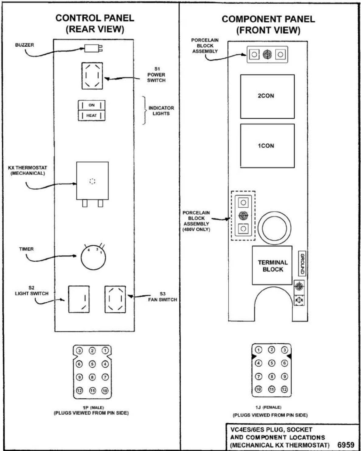
VC4ES/6ES with Mechanical KX thermostat - Plug, Socket and Components
VC4ED/6ED with Solid State Control - Plug, Socket and Components

VC4EC/6EC - Plug, Socket and Components (Cook & Hold Standard)


flowchart
graph TD
    A["PORCELAIN BLOCK ASSEMBLY"] --> B["N IN H"]
    B --> C["T1 TRANSFORMER"]
    C --> D["OUT"]
    D --> E["2CON"]
    E --> F["1CON"]
    F --> G["SOLID STATE RELAY (SSR1)"]
    G --> H["LOAD"]
    H --> I["INPUT"]
    I --> J["LOAD"]
    J --> K["SOLID STATE RELAY (SSR2)"]
    K --> L["OUTPUT"]
    L --> M["TERMINAL BLOCK"]
    M --> N["GROUND"]
    N --> O["1J (FEMALE)"]
    O --> P["(PLUG VIEWED FROM PIN SIDE)"]
    P --> Q["VC4ED/6ED PLUG, SOCKET AND COMPONENT LOCATIONS (COMPUTER CONTROL)"]
    Q --> R["6961"]
VC4ES, VC6ES with Mechanical KX Thermostat
Schematic diagram 6532 will be used to explain the electrical sequence of operation.
Cook Cycle
- Conditions.
A. Oven connected to correct voltage and is properly grounded.
B. Power switch (S1) OFF.
C. Temperature dial set to lowest temperature (fully CCW).
D. High limit thermostat CLOSED.
E. Oven doors closed (door switch contacts CLOSED).
F. Oven cavity temperature below 140^ F.
- Power switch (S1) turned ON.
A. Power ON light (Amber) comes ON.
B. 1CON coil energized.
C. Blower motor energized.
NOTE: Motor speed (Hi/Low) depends on position of fan speed switch (S3).
D. Component cooling fan energized.
E. Power to oven cavity light switch (S3) wire #1. Turns cavity lights ON/OFF and does not affect "Cook" cycle.
- Set thermostat to desired "Cook" temperature and thermostat CLOSES.
A. Heating light (Clear) comes ON.
B. 2CON coil energized.
1) Heating elements powered and heating starts.
- Oven reaches set temperature and thermostat OPENS.
A. Heat light goes out.
B. 2CON coil de-energized.
1) Power removed from heating elements and heating stops.
- The oven will continue to cycle on the thermostat until the doors are opened or the power switch (S1) is turned to the OFF or COOL DOWN position.
VC4ED, VC6ED with Solid State Temperature Control
Schematic diagram 6534 will be used to explain the electrical sequence of operation.
Cook Cycle
- Conditions.
A. Oven connected to correct voltage and is properly grounded.
B. Power switch (S1) OFF.
C. Temperature dial set to lowest temperature (fully CCW).
D. High limit thermostat CLOSED.
E. Oven doors closed (door switch contacts CLOSED).
F. Oven cavity temperature below 140^ F.
- Power switch (S1) turned ON.
A. Power ON light (Amber) comes ON.
B. 1CON coil energized.
C. Solid state temperature control energized.
1) Heating light (Clear) comes ON.
2) 2CON coil energized.
a. Heating elements powered and heating starts.
D. Blower motor energized.
NOTE: Motor speed (Hi/Low) depends on position of fan speed switch (S3).
E. Component cooling fan energized.
F. Power to oven cavity light switch (S3) wire #1. Turns cavity lights ON/OFF; does not affect "Cook" cycle.
-
Set temperature dial to desired "Cook" temperature.
-
Oven reaches set temperature.
A. Temperature control de-energizes internal relay and the normally open (N.O.) contacts OPEN.
1) Heat light goes out.
2) 2CON coil de-energized.
a. Power removed from heating elements and heating stops.
- The oven will continue to cycle on the temperature control until the doors are opened or power switch (S1) is turned to the OFF or COOL DOWN position.
Timer Cycle, Cooking
(KX Thermostat or Solid State Control)
NOTE: The "Cook" timer operates independently of the heating cycle. Additional time can be set or the timer can be turned OFF throughout the cooking cycle.
-
With the power switch turned ON, power is supplied to "Cook" timer terminal 1.
-
Set "Cook" timer to desired time.
A. Contacts 1 & 3 close, timer motor is energized and timing "down" begins.
- Time expires on "Cook" timer.
A. Contacts 1 & 3 open, timer motor is de-energized and timing stops.
B. Contacts 1 & 4 close.
1) Buzzer energized and sounds.
NOTE: The buzzer continues to sound until the timer dial is set to the OFF position or additional time is set.
Cool Down Cycle (KX Thermostat or Solid State Control)
- Conditions.
A. Oven is ON.
B. Oven cavity temperature needs to be lowered.
C. Doors are open (door switch contacts OPEN).
D. Fan speed switch (S3) set to "Hi".
- Power Switch (S1) turned to COOL DOWN.
A. Power ON light (Amber) goes out.
B. Convection fan motor energized.
NOTE: Fan speed switch (S3) can be set to operate at high or low fan speed.
- If doors are CLOSED (door switch contacts CLOSED):
A. Power ON light (Amber) comes ON.
B. 1CON coil is energized but heating elements are not powered.
C. Component cooling fan energized.
D. Power is supplied to:
1) "Cook" timer terminal 1. If a time is dialed, timer will operate and buzzer will sound when timer reaches zero.
2) Oven cavity light switch (S3) wire #1. Turns cavity lights ON/OFF; does not affect "Cool down" cycle.
- The oven will remain in this condition until the power switch (S1) is turned to the OFF or ON position.
VC4EC, VC6EC (Computer Control)
Schematic diagram 6536 will be used to explain the electrical sequence of operation or both the "Cook" cycle and the "Cook and Hold" cycle.
Cook Cycle
- Conditions.
A. Oven connected to correct voltage and is properly grounded.
B. Power switch (S1) OFF.
C. Computer control is setup properly and ready to use.
NOTE: The set point temperature of the computer control will be the last temperature that was set.
D. High limit thermostat CLOSED.
E. Oven doors closed (door switch contacts CLOSED).
F. Oven cavity temperature below 140^ F.
- Power switch (S1) turned ON.
A. 1CON coil energized.
B. 24VAC transformer (T1) is energized.
1) Computer control is energized and performs a power ON self test before energizing outputs. If the control passes self test, then the outputs are energized and operation sequence continues. If control does not pass self test then the corresponding error code is displayed.
C. Component cooling fan energized.
D. Power is connected to:
1) Terminal 1 on solid state relay 1 (SSR1 - load side) and solid state relay 2 (SSR2 - load side).
2) Pin 3 (C3-3) on computer control (input "IN-2").
3) Oven cavity light switch (S2). Turns cavity lights ON/OFF; does not affect "Cook" cycle.
- Computer control senses oven cavity temperature through probe input. With the oven cavity temperature below set point, the output from pin C3-2 is activated.
A. Oven "Heat Light" on the control comes ON.
B. 2CON coil energized.
1) Heating elements powered and heating starts.
C. The controls 5VDC output from pins C2-2 (-) and C2-8 (+) is activated and SSR1 relay is energized.
1) Convection fan motor is energized (High speed).
- Oven reaches set point temperature.
A. Computer control de-activates the output from pin C3-2.
1) 2CON coil de-energized.
a. Power removed from heating elements and heating stops.
B. Oven "Heat Light" on the control goes out.
C. Oven "Ready Light" on the control comes ON.
D. Electronic beeper sounds momentarily.
- The oven will continue to cycle on the computer control until the doors are opened or power switch (S1) is turned to the OFF or COOL DOWN position.
Temperature and Time Cycle (Cooking)
NOTE: The computers internal "Cook" timer operates independently of the heating cycle. Additional time can be set or the timer can be stopped and re-started throughout the cooking cycle.
Refer to the Instructions Manual for specific operating instructions of the oven Computer Control.
Cook and Hold Cycle
NOTE: For a detailed explanation of the "Cook & Hold" mode, refer to the Instructions Manual as outlined under SETTING THE OVEN FOR COOK & HOLD and COOK & HOLD OPERATION.
In "Cook & Hold" mode, the operation of the computer control is identical to the normal Cook Cycle with these exceptions:
- Oven "Cook & Hold" light on the control comes ON.
- Convection fan will operate at Low speed, throughout the "Cook & Hold" cycle.
A. The computer control 5VDC output from pins C2-2 (-) and C2-8 (+) is de-activated and SSR1 relay is de-energized.
1) Power is removed from convection fan motor high speed terminal.
B. The computer control 5VDC output from pins C2-1 (-) and C2-8 (+) is activated and SSR2 relay is energized.
1) Power is applied to the convection fan motor low speed terminal.
-
At the end of the "Cook" time, the electronic beeper sounds momentarily to indicate the end of first stage cooking (oven operates normally at the temperature and time selected until time expires).
-
The display flashes HOLD as the oven enters HOLD mode. This is also considered second stage cooking (oven heating stops but product continues to cook on residual heat).
A. Convection fan motor is de-energized.
- After the oven temperature drops below 150^ F, the heat comes back ON and cycles as needed, to maintain the "Hold" temperature of 150^ F.
A. Convection fan motor energized (Low speed).
- The oven continues to cycle in this manner until one of the following occurs:
A. The "Cook & Hold" mode is turned OFF.
B. Power switch (S1) is turned to the OFF or COOL DOWN position.
Cool Down Cycle
- Conditions.
A. Oven is ON.
B. Oven cavity temperature needs to be lowered.
C. Doors are open (door switch contacts OPEN).
D. Power switch (S1) set to either ON or OFF.
- Power Switch (S1) turned to COOL DOWN.
A. Power is connected through power switch (S1) to the convection fan motor high speed terminal.
1) Convection fan motor energized (High speed).
- The oven will continue to operate in COOL DOWN mode until the power switch (S1) is turned to the OFF or ON position.
SCHEMATICS
VC4ES, VC6ES with Mechanical (KX) Controls, 208-240V
VC4ES & VC6ES 208-240V.
USE FIELD WIRE SUITABLE FOR 90°C.
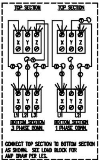
208 OR 240 VOLT 1 PHASE SUPPLY 208 OR 240 VOLT 3 PHASE SUPPLY

DERRIVED FROM: 426661-1 REV. C
SEE WIRING DIAGRAM 426660 (6968, 6969)
VC4ES, VC6ES with Mechanical (KX) Controls, 480V
VC4ES & VC6ES 480V.
USE FIELD WIRE SUITABLE FOR 90°C.

DERRIVED FROM: 426663-1 REV. C
SEE WIRING DIAGRAM 426662 (6970, 6971)
VC4ED, VC6ED with Solid State Temperature Control, 208-240V
VC4ED & VC6ED 208-240V.
USE FIELD WIRE SUITABLE FOR 90°C.
208 OR 240 VOLT 1 PHASE SUPPLY 208 OR 240 VOLT 3 PHASE SUPPLY

DERRIVED FROM:
426667-1 REV. D SEE WIRING DIAGRAM 426666 (6972, 6973)
VC4ED, VC6ED with Solid State Temperature Control, 480V
VC4ED & VC6ED 480V.
USE FIELD WIRE SUITABLE FOR 90°C.

426669-1 REV. D SEE WIRING DIAGRAM 426668 (6974, 6975)
VC4EC, VC6EC Computer Control, 208-240V (Roast & Hold Standard)
VC4EC & VC6EC 208-240V.

VC4EC, VC6EC Computer Control, 480V (Roast & Hold Standard)
VC4EC & VC6EC 480V.
USE FIELD WIRE SUITABLE FOR 90°C.

DERRIVED FROM:
426675-1 REV. D SEE WIRING DIAGRAM 426674 (6978, 6979)
THIS PAGE PURPOSELY LEFT BLANK
WIRING DIAGRAMS
VC4ES, VC6ES with Mechanical (KX) Control, 208-240V

| 9 | AB | WIRE NUT BLUE | - | |
| 2 | Y | LAMP ASSEMBLY 120V. 40V. | - | |
| 1 | X | SWITCH, TOGGLE BP.DT. (CD) | - | |
| 1 | V | MOTOR 1/3 HP. 2 SPEED GE. | - | |
| 2 | T | CONTACTOR 40A 3 POLE | - | |
| 1 | S | TERMINAL BLOCK 3 POLE | - | |
| 2 | R | FUSE & HOLDER 15A | HOLDER | |
| FUSE | ||||
| 6 | L | ELEMENT, 2.0 KW | 208 VOLT | |
| 240 VOLT | ||||
| 1 | K | LIMIT CONTROL 550F | - | |
| 1 | J | BLOCK/PORCELIAN ASSEMBLY | - | |
| 1 | H | SWITCH, LIMIT (ODDR) | - | |
| 1 | G | BUZZER 230 VOLT | - | |
| 1 | F | TIMER, 230 VOLT | 1-HR, 60 HZ. | |
| 5-HR, 60 HZ. | ||||
| 1 | E | TEMP. CONTROL "KX-112" | - | |
| 1 | D | FAN, COOLING 230 V. | - | |
| 1 | C | LIGHT, "POWER ON",HEATING* 250V. | - | |
| 1 | B | SWITCH, TOGGLE BP.DT | - | |
| 1 | A | SWITCH, TOGGLE S.P.S.T | - | |
| RNG | m. | DESCRIPTION | FK. | |

flowchart
graph TD
    A["ON/OFF/COOL DOWN"] --> B["POWER ON"]
    B --> C["HEATING"]
    C --> D["THERMOSTAT"]
    D --> E["LIGHTS"]
    E --> F["SPEED"]
    F --> G["BUZZ"]
    G --> H["ONIL"]
    H --> I["MANLE CONNECTOR (SHORT)"]
    style A fill:#f9f,stroke:#333
    style B fill:#ccf,stroke:#333
    style C fill:#cfc,stroke:#333
    style D fill:#fcc,stroke:#333
    style E fill:#cff,stroke:#333
    style F fill:#ffc,stroke:#333
    style G fill:#cfc,stroke:#333
    style H fill:#fcc,stroke:#333
    style I fill:#fff,stroke:#333
PAGE 1 OF 2
(SEE 6969) 6968

VC4ES, VC6ES with Mechanical (KX) Control, 480V
| 9 | AB | WIRE NUT BLUE | - | |
| 1 | Z | TRANSFORMER 1KVA 480-240 V. | - | |
| 2 | Y | LAMP ASSEMBLY 120V, 40V. | - | |
| 1 | X | SWITCH, TOGGLE D.P.D.T. (COD) | - | |
| 1 | V | MOTOR 1/3 HP. 2 SPEED G.E. | - | |
| 2 | T | CONTACTOR 40A 3 POLE | - | |
| 1 | S | TERMINAL BLOCK 3 POLE | - | |
| 2 | R | FUSE & HOLDER ISA | HOLDER | |
| FUSE | ||||
| 5 | L | ELEMENT, 2.0 KW. 480V. | - | |
| 1 | K | LIMIT CONTROL 550F | - | |
| 2 | J | BLOCK,PORCELIAN ASSEMBLY | - | |
| 2 | H | SWITCH, LIMIT (DOOR) | - | |
| 1 | G | BUZZER 230 VOLT | - | |
| 1 | F | TIMER, 230 VOLT | 1-HR, 60 HZ | |
| 5-HR, 60 HZ. | ||||
| 1 | E | TEMP. CONTROL "KX-112" | - | |
| 1 | D | FAN, COOLING 230 V. | - | |
| 1 | C | LIGHT, "POWER ON",HEATING' 250V. | - | |
| 1 | B | SWITCH, TOGGLE D.P.D.T | - | |
| 1 | A | SWITCH, TOGGLE S.P.S.T | - | |
| REQ | PI. | DESCRIPTION | FKL | |

flowchart
graph TD
    A["ON/OFF/COOL DOWN"] --> B["POWER ON HEATING"]
    B --> C["THERMOSTAT"]
    C --> D["TIMER"]
    D --> E["LUCK"]
    E --> F["BUZZ"]
    F --> G["LIGHTS"]
    G --> H["10"]
    H --> I["2"]
    I --> J["3"]
    J --> K["4"]
    K --> L["5"]
    L --> M["6"]
    M --> N["7"]
    N --> O["8"]
    O --> P["9"]
    P --> Q["10"]
    Q --> R["11"]
    R --> S["12"]
    S --> T["MALE CONNECTOR (SHORT)"]

    subgraph System
        U["1"] --> V["2"]
        V --> W["3"]
        W --> X["4"]
        X --> Y["5"]
        Y --> Z["6"]
        Z --> AA["7"]
        AA --> AB["8"]
        AB --> AC["9"]
        AC --> AD["10"]
        AD --> AE["11"]
        AE --> AF["12"]
    end

    style A fill:#f9f,stroke:#333
    style B fill:#ccf,stroke:#333
    style C fill:#cfc,stroke:#333
    style D fill:#fcc,stroke:#333
    style E fill:#cff,stroke:#333
    style F fill:#ffc,stroke:#333
    style G fill:#cfc,stroke:#333
    style H fill:#fcc,stroke:#333
    style I fill:#ffc,stroke:#333
    style J fill:#cfc,stroke:#333
    style K fill:#cfc,stroke:#333
    style L fill:#cfc,stroke:#333
    style M fill:#cfc,stroke:#333
    style N fill:#cfc,stroke:#333
    style O fill:#cfc,stroke:#333
    style P fill:#cfc,stroke:#333
    style Q fill:#cfc,stroke:#333
    style R fill:#cfc,stroke:#333
    style S fill:#cfc,stroke:#333
    style T fill:#cfc,stroke:#333
    style U fill:#fcc,stroke:#333
    style V fill:#fcc,stroke:#333
    style W fill:#fcc,stroke:#333
    style X fill:#fcc,stroke:#333
    style Y fill:#fcc,stroke:#333
    style Z fill:#fcc,stroke:#333
    style AA fill:#fcc,stroke:#333
    style AB fill:#fcc,stroke:#333
    style AC fill:#fcc,stroke:#333
    style AD fill:#fcc,stroke:#333
    style AE fill:#fcc,stroke:#333
    style AF fill:#fcc,stroke:#333
    style AG fill:#fcc,stroke:#333
    style AH fill:#fcc,stroke:#333
    style AI fill:#fcc,stroke:#333
    style AJ fill:#fcc,stroke:#333
    style AK fill:#fcc,stroke:#333
    style AL fill:#fcc,stroke:#333
    style AM fill:#fcc,stroke:#333
    style AN fill:#fcc,stroke:#333
    style AO fill:#fcc,stroke:#333
    style AP fill:#fcc,stroke:#333
    style AQ fill:#fcc,stroke:#333
    style AR fill:#fcc,stroke:#333
    style AS fill:#fcc,stroke:#333
    style AT fill:#fcc,stroke:#333
    style AU fill:#fcc,stroke:#333
    style AV fill:#fcc,stroke:#333
    style AW fill:#fcc,stroke:#333

VC4ED, VC6ED with Solid State Temperature Control, 208-240V

| 9 | AB | VIRE NUT BLUE | - | |
| 2 | Y | LAMP ASSEMBLY 120V. 40W. | - | |
| 1 | X | SWITCH, TOGGLE D.P.D.T. (CD) | - | |
| 1 | V | MOTOR 1/3 HP, 2 SPEED GE. | - | |
| 2 | T | CONTACTOR 40A 3 POLE | - | |
| 1 | S | TERMINAL BLOCK 3 POLE | - | |
| 2 | R | FUSE & HOLDER ISA | HOLDER | |
| FUSE | ||||
| 1 | P | PROBE,THERMISTOR | - | |
| 6 | L | ELEMENT, 2.0 KW | 208 VOLT | |
| 240 VOLT | ||||
| 1 | K | LIMIT CONTROL 550F | - | |
| 1 | J | BLOCK,PORCELIAN ASSEMBLY | - | |
| 1 | H | SWITCH, LIMIT (DOOR) | - | |
| 1 | G | BUZZER 230 VOLT | - | |
| 1 | F | TIMER, 230 VOLT | 1-HR, 60 HZ. | |
| 5-HR, 60 HZ. | ||||
| 1 | E | TEMP. CONTROL 'G-S' | - | |
| 1 | D | FAN, COOLING 230 V. | - | |
| 1 | C | LIGHT, "POWER ON",HEATING' 250 V. | - | |
| 1 | B | SWITCH, TOGGLE D.P.D.T | - | |
| 1 | A | SWITCH, TOGGLE S.P.S.T | - | |
| REQ. | IT. | DESCRIPTION | PM | |
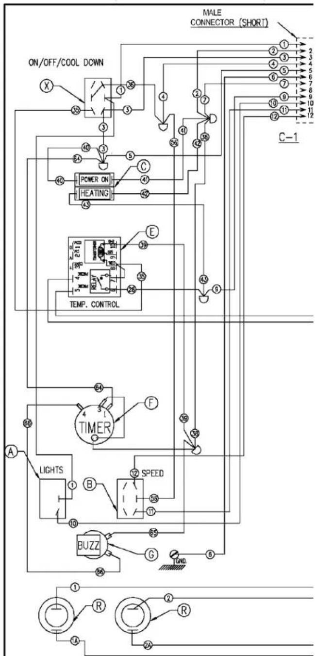
flowchart
graph TD
    A["ON/OFF/COOL DOWN"] --> B["POWER ON"]
    B --> C["HEATING"]
    C --> D["TEMP. CONTROL"]
    D --> E["TIMER"]
    E --> F["SPEED"]
    F --> G["BUZZ"]
    G --> H["Light"]
    H --> I["LIGHTS"]
    I --> J["TIME"]
    J --> K["MALE CONNECTOR (SHORT)"]
    style A fill:#f9f,stroke:#333
    style B fill:#ccf,stroke:#333
    style C fill:#cfc,stroke:#333
    style D fill:#fcc,stroke:#333
    style E fill:#cff,stroke:#333
    style F fill:#ffc,stroke:#333
    style G fill:#cfc,stroke:#333
    style H fill:#fcc,stroke:#333
    style I fill:#ffc,stroke:#333
    style J fill:#cfc,stroke:#333
    style K fill:#fcc,stroke:#333
PAGE 1 OF 2
(SEE 6973) 6972
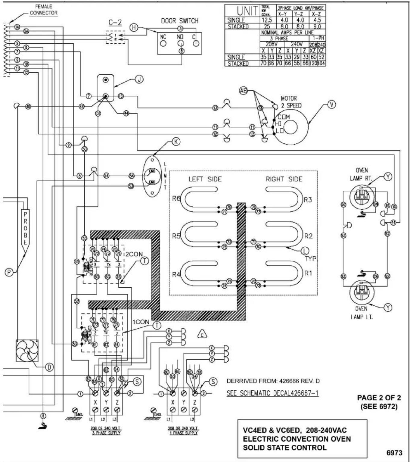
VC4ED, VC6ED with Solid State Temperature Control, 480V

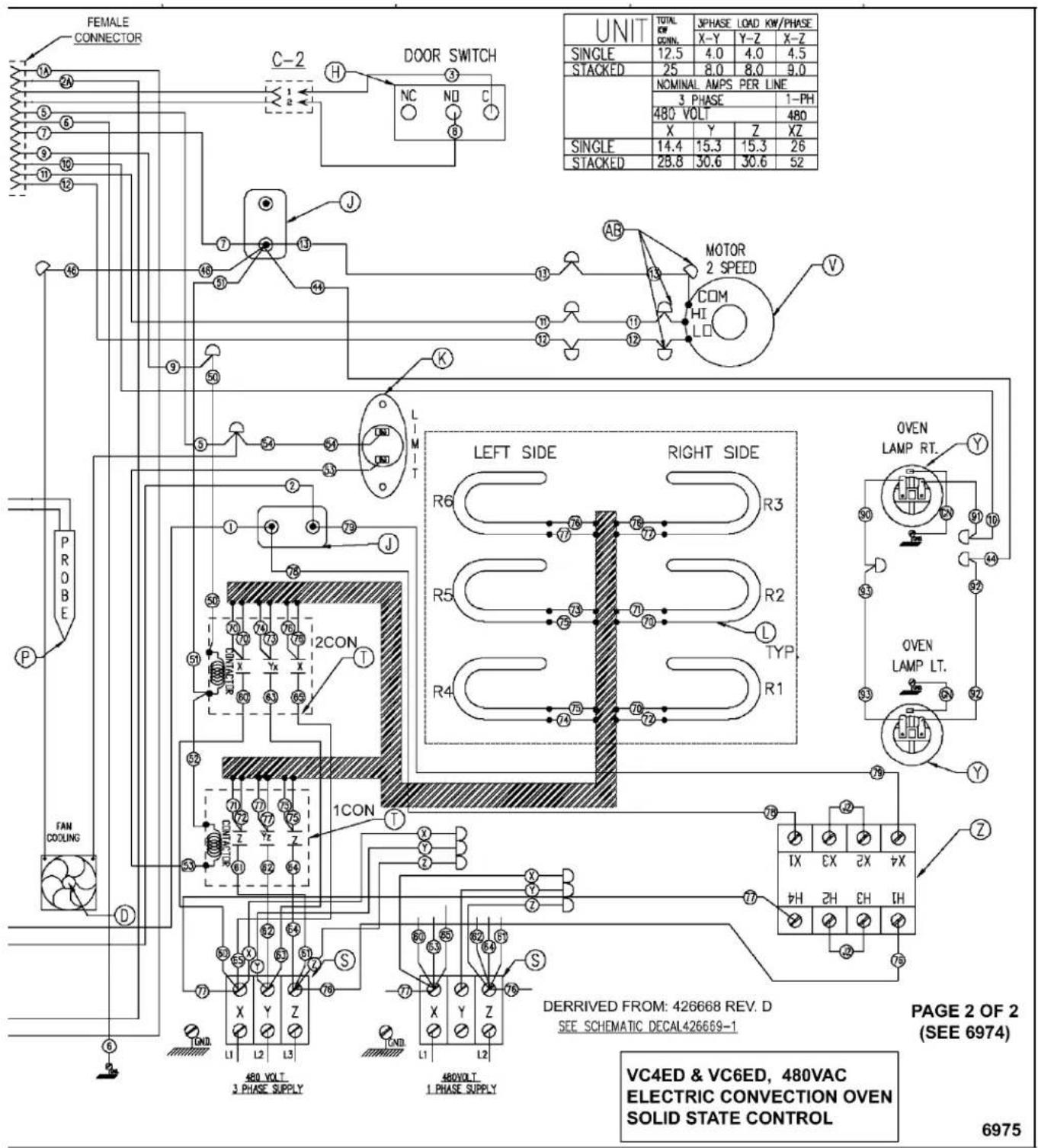
VC4EC, VC6EC Computer Control, 208-240V (Roast & Hold Standard)
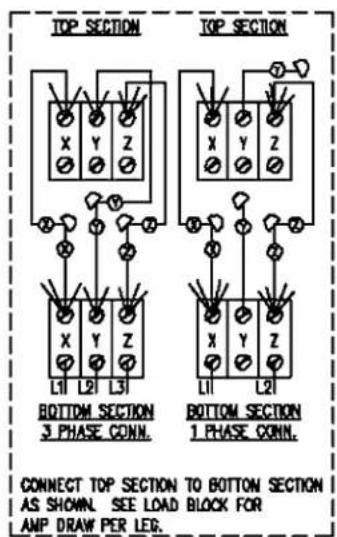
| 9 | AB | WIRE NUT BLUE | - |
| 2 | Y | LAMP ASSEMBLY 120V. 40W. | - |
| 1 | V | MOTOR 1/3 HP. 2 SPEED GE. | - |
| 2 | T | CONTACTOR 40A 3 POLE | - |
| 1 | S | TERMINAL BLOCK 3 POLE | - |
| 2 | R | FUSE & HOLDER 15A HOLDER\nFUSE | |
| 1 | P | TRANSFORMER, 240/24 40VA | - |
| 6 | L | ELEMENT, 20 KW 208 VOLT\n240 VOLT | |
| 1 | K | LIMIT CONTROL 550F | - |
| 1 | J | BLOCK,PORCELIAN ASSEMBLY | - |
| 1 | H | SWITCH, LIMIT (DDR) | - |
| 1 | G | ALARM 12 V. DC | - |
| 2 | F | RELAY, SQLID STATE 50A | - |
| 1 | E | FAN, COOLING 230 V. | - |
| 1 | DI | PROBE, THERMOCOUPLE | - |
| 1 | D | CONTROLLER WATLOW 734 | - |
| 1 | B | SWITCH, DVEN LIGHT | - |
| 1 | A | SWITCH, MAIN POWER D.P.D.T. CENT.OFF- | |
| REQ. | PT. | DESCRIPTION | PM. |

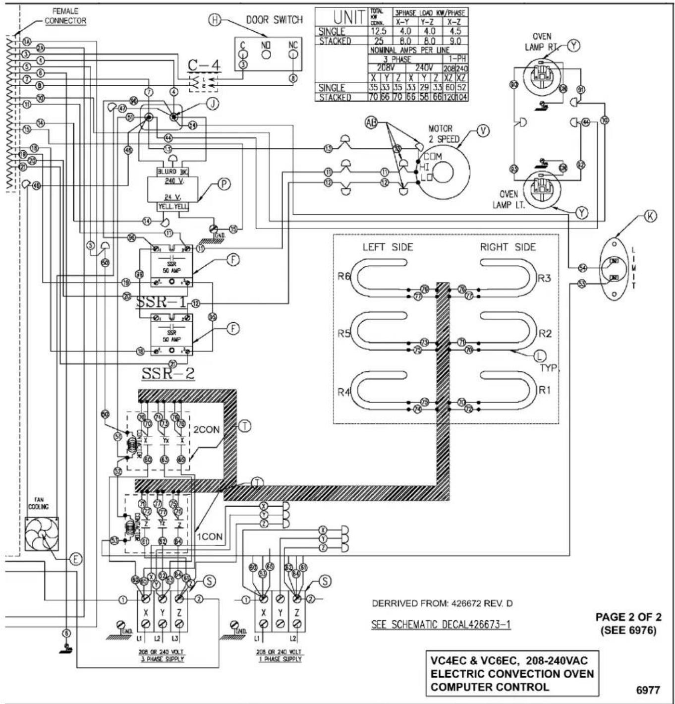
VC4EC, VC6EC Computer Control, 480V (Roast & Hold Standard)

| 9 | AB | VIRE NUT BLUE | - |
| 1 | Z | TRANSFORMER 1KVA 400-240 V. | - |
| 2 | Y | LAMP ASSEMBLY 120V 40V. | - |
| 1 | V | HOTOR 1/3 HP 2 SPECO GE. | - |
| 2 | T | CONTACTOR 40A 3 POLE | - |
| 1 | S | TERMINAL BLOCK 3 POLE | - |
| 2 | R | FUSE & HOLDER 15A HOLDERSUSE | |
| 1 | P | TRANSFORMER, 240/24 40VA | - |
| 6 | L | ELEMENT, 2.0 KW. 400V. | - |
| 1 | K | LIMIT CONTROL 550F | - |
| 2 | J | BLOCK.PORCELIAN ASSEMBLY | - |
| 1 | H | SWITCH, LIMIT (DOOR) | - |
| 1 | G | ALARM 12 V. DC | - |
| 2 | F | RELAY, SOLID STATE 50A | - |
| 1 | E | FAN, COOLING 230 V. | - |
| 1 | DI | PROPE, THERMOCOUPLE | - |
| 1 | D | CONTROLLER VATLOW 734 | - |
| 1 | B | SWITCH, OVEN LIGHT | - |
| 1 | A | SWITCH, MAIN POWER BP.D.T. CENT.OF | F- |
| RSG. | IT. | DESCRIPTION | PIN. |
6978
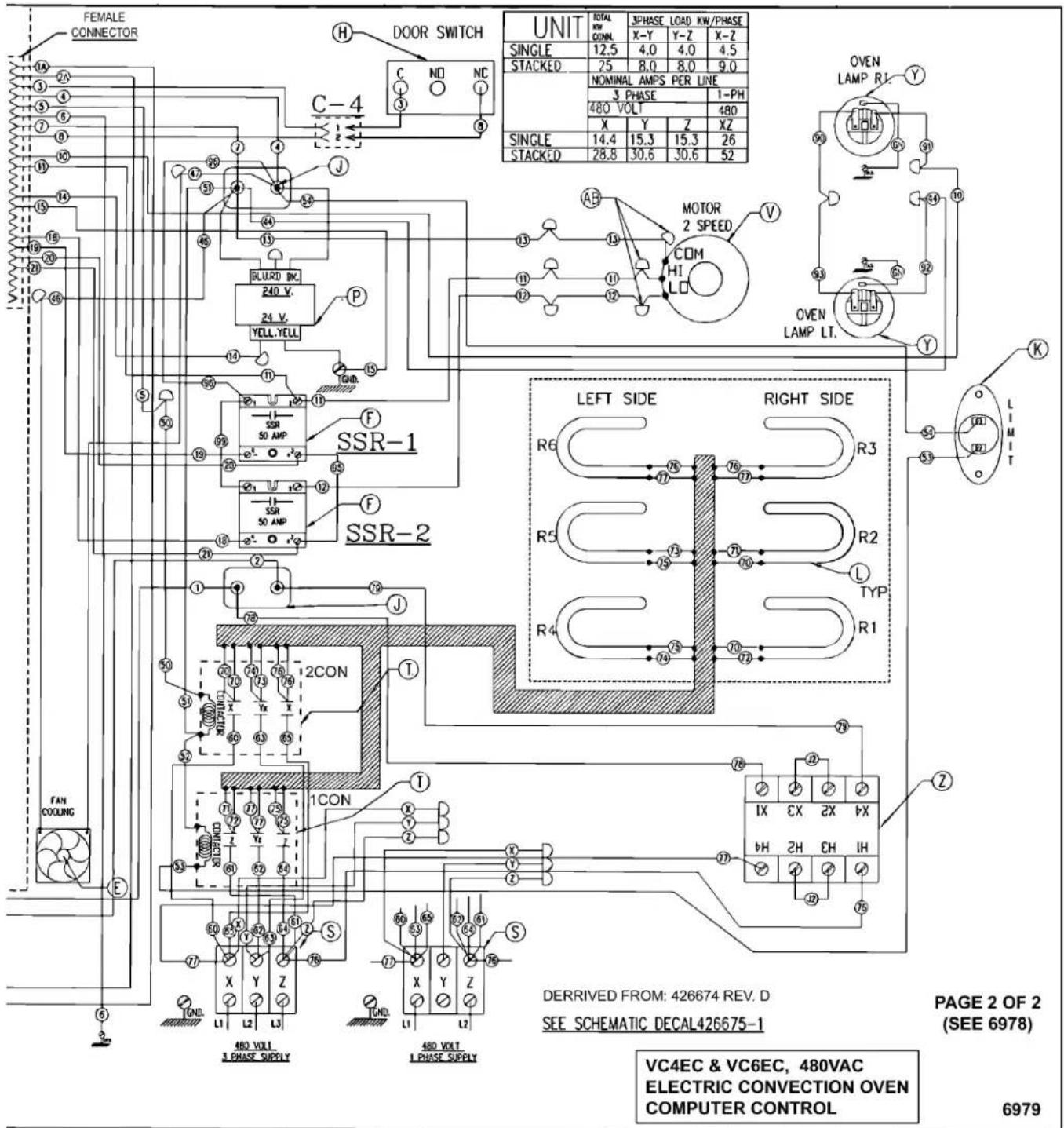
TROUBLESHOOTING
⚠ WARNING Certain procedures in this section require electrical test or measurements while power is applied to the machine. Exercise extreme caution at all times. If test points are not easily accessible, disconnect power and follow lockout / tagout procedures, attach test equipment and reapply power to test.
ALL MODELS
| SYMPTOMS POSSIBLE CAUSES | |
| Blower motor doesn’t run with power switch in "ON" "COOL DOWN" or position. | 1. Line voltage incorrect.2. Power switch (S1) malfunction.3. Fan speed switch (S3) malfunction.4. Interconnecting wiring malfunction.5. Motor inoperative. |
| Blower motor doesn’t run with power switch "ON", but oven heats. | 1. Door switch malfunction.2. Interconnecting wiring malfunction.3. Motor inoperative. |
| Blower motor doesn’t run in "Cool Down", but runs ok in "ON" position. | 1. Power switch (S1) malfunction.2. Fan speed switch (S3) malfunction.3. Interconnecting wiring malfunction. |
| Excessive or low heat in oven. 1. Line voltage incorrect. | 2. Heating element malfunction.3. Contactor malfunction.4. Convection Fan motor malfunction.5. Temperature probe malfunction or mechanical thermostat malfunction.6. Temperature control not calibrated.7. Temperature control malfunction. |
| Mechanical Timer inoperative or not functioning properly. | 1. Interconnecting wiring malfunction.2. Line voltage incorrect.3. Timer malfunction. |
| Component cooling Fan does not run. 1. Motor inoperable. | 2. Interconnecting wiring malfunction. |
| Uneven Cooking. 1. Convection Fan motor speed/direction. | 2. Air flow Baffles missing or damaged.3. Line voltage incorrect.4. Heating element(s) malfunction.5. Contactor malfunction. |
| Intermittent operation problems. 1. High ambient temperatures. | 2. Wiring connections loose.3. Cooling fan malfunction. |
| No power to oven controls. 1. Main circuit breaker OPEN. | 2. Control circuit fuses OPEN.3. Power switch (S1) inoperative.4. Transformer (T2) inoperative (480V only). |
| No heat, convection fan motor runs. 1. High limit thermostat OPEN. | 2. Heating element malfunction.3. Contactor malfunction.4. Temperature control malfunction. |
| No power to temperature control. 1. Power switch (S1) in "Cool Down". | 2. Door or door switch open. |
| Door does not seal or shut properly 1. Doors out of adjustment. | 2. Door chain out of adjustment or broken (simultaneous doors).3. Door catch roller out of adjustment or broken (independent doors).4. Door seals damaged. |
COMPUTER CONTROL MODELS ONLY
| SYMPTOM POSSIBLE CAUSES | |
| Oven does not heat. 1. High limit switch open. | 2. Temperature probe malfunction.3. Computer control malfunction. |
| High limit thermostat shutting OFF heat. 1. Temperature probe malfunction. | 2. Computer control malfunction. |
| Oven not hot enough. 1. Temperature probe malfunction. | 2. Computer control range high (rH1) setting to low. See SETUP MODE under COMPUTER CONTROL.3. Computer control malfunction. |
| Blower motor doesn’t run with power switch in "ON" or "COOL DOWN" position. | 1. Line voltage incorrect.2. Power switch (S1) malfunction.3. Fan speed switch (S3) malfunction.4. Solid sate relay (SSR) malfunction. See SOLID STATE RELAY TEST under COMPUTER CONTROL.5. Interconnecting wiring malfunction.6. Motor inoperative.7. Computer control malfunction. See COMPUTER CONTROL OPERATIONAL TEST. |
Error Codes
In the display window, the error code will alternate between the code and the oven cavity temperature or dashes if the oven is calling for heat (heat light on). The exact error code displayed will depend on the priority assigned to the problem in the EPROM'S software. The lower the error code number, the higher the priority. If more than one problem occurs at the same time, the error code assigned to the higher priority problem will be displayed. Refer to the error code table below to solve the problem. If the lower priority problem still exists, the next error code will be displayed. When the condition causing the error is resolved, normal oven operation can resume.
NOTE: To check a "Setup Parameter" and its corresponding "Data Value", see SETUP MODE under COMPUTER CONTROL.
NOTE: If the cause of the error is not apparent, check for these conditions as they may also cause errors to occur: Electrical noise or a noise event, excess environmental moisture or temperature, or vibration.
| CODE & PROBLEM PROBALE CAUSE SOLUTION | ||
| Er01 - ROM checksum error Internal | ROM malfunction Cycle power | |
| Er02 - RAM checksum error Internal | RAM malfunction Cycle power | |
| Er03 - Ambient sensor error | Ambient temperature is below 32°F | Check ambient temperature at the control. |
| Er04 - Configuration error Microprocessor | malfunction Cycle power | |
| Er05 - EPROM error^1 | Power loss while storing data Cycle power | |
| Er06 - Zone 1 A/D underflow error • Incorrect sensor type• Measuring temperature outside the sensor range | • Check the InP1 setup parameter. Verify it matches your sensor.• Check sensor and connections for a reversed or open sensor. If the condition causing the error is resolved, the error will clear. | |
| Er07 - Zone 1 A/D overflow error Open sensor • Check the InP1 setup parameter. | Verify it matches your sensor.• Check sensor and connections for a reversed or open sensor. If the condition causing the error is resolved, the error will clear. | |
| Er10 - Stack overflow error Microprocessor malfunction • Cycle power | • Check sensor and connections for a reversed or open sensor | |
| Er11 - Open sensor error | Open sensor • Check the InP1 setup parameter. | Verify it matches your sensor.• Check sensor and connections for a reversed or open sensor |
| Er12 - Shorted sensor | • Incorrect sensor type• Measuring temperature outside the sensor range | • Check the InP1 setup parameter. Verify it matches your sensor.• Check sensor and connections for a reversed or open sensor |
| NOTE: 1. Should only see when a new EPROM is installed and powered for the first time. | ||
-NOTES-
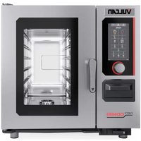
- VC4E & VC6E SERIES
- FULL SIZE ELECTRIC CONVECTION OVENS
- - NOTICE -
- TABLE OF CONTENTS
- GENERAL 4
- REMOVAL AND REPLACEMENT OF PARTS ....
- SERVICE PROCEDURES AND ADJUSTMENTS......
- Schematics 37
- Wiring Diagrams 44
- TROUBLESHOOTING 56
- GENERAL
- INTRODUCTION
- INSTALLATION
- OPERATION
- CLEANING
- LUBRICATION
- TOOLS
- Standard
- Special
- SPECIFICATIONS
- REMOVAL AND REPLACEMENT OF PARTS
- COVERS AND PANELS
- Top Front Cover
- Bottom Front Cover
- Control Panel
- Right Side Panel
- Left Side Panel
- CONTROL PANEL COMPONENTS
- Removable Components
- COMPONENT PANEL COMPONENTS
- TEMPERATURE PROBE (SOLID STATE CONTROL)
- HEATING ELEMENTS
- Front Access
- Alternate Access
- BLOWER AND MOTOR
- DOOR SWITCH
- DOOR WINDOW
- OVEN DOORS AND BEARINGS (INDEPENDENT DOORS)
- OVEN DOORS (SIMULTANEOUS DOORS)
- Assembly Removal
- Disassembly
- ROLLER LATCH ASSEMBLY (INDEPENDENT DOORS)
- DOOR CATCH ROLLER ASSEMBLY (INDEPENDENT DOORS)
- MECHANICAL (KX) THERMOSTAT
- HIGH LIMIT THERMOSTAT
- INTERIOR LIGHTS
- Lamp
- Lamp Assembly
- COOLING FAN
- SERVICE PROCEDURES AND ADJUSTMENTS
- SOLID STATE TEMPERATURE CONTROL CALIBRATION
- MECHANICAL (KX) THERMOSTAT CALIBRATION
- SOLID STATE TEMPERATURE CONTROL TEST
- TEMPERATURE PROBE TEST (SOLID STATE CONTROL)
- HEATING ELEMENT TEST
- BLOWER ADJUSTMENT
- DOOR ADJUSTMENT
- DOOR STRIKE ADJUSTMENT (INDEPENDENT DOORS)
- DOOR CATCH ROLLER ADJUSTMENT
- (INDEPENDENT DOORS)
- DOOR SWITCH ADJUSTMENT
- DOOR CHAIN ADJUSTMENT (SIMULTANEOUS DOORS)
- Procedure
- COMPUTER CONTROL
- Setup Mode
- Probe Test
- Solid State Relay Test
- COMPUTER CONTROL TEMPERATURE CALIBRATION
- COMPUTER CONTROL OPERATIONAL TEST
- - Heat comes ON
- - Convection fan comes ON (High or Low speed SSR is energized).
- - Electronic beeper (external) sounds.
- WARNING Disconnect the electrical power to the machine and follow lockout / tagout procedures.
- Solid State temperature
- COMPONENT LOCATION
- VC4ES, VC6ES with Mechanical KX Thermostat
- Cook Cycle
- VC4ED, VC6ED with Solid State Temperature Control
- Timer Cycle, Cooking
- (KX Thermostat or Solid State Control)
- Cool Down Cycle (KX Thermostat or Solid State Control)
- VC4EC, VC6EC (Computer Control)
- Temperature and Time Cycle (Cooking)
- Cook and Hold Cycle
- Cool Down Cycle
- SCHEMATICS
- VC4EC, VC6EC Computer Control, 480V (Roast & Hold Standard)
- WIRING DIAGRAMS
- TROUBLESHOOTING
- COMPUTER CONTROL MODELS ONLY
- Error Codes
Brand : Vulcan
Model : VC44ED-480
Category : Oven