
DMX 5.3 Splitter - Audio/video converter MARTIN - Free user manual and instructions
Find the device manual for free DMX 5.3 Splitter MARTIN in PDF.


| Product Type | DMX512 Signal Splitter |
| Model | DMX 5.3 Splitter |
| Brand | Martin |
| Dimensions (W x H x D) | 19 x 1.75 x 6 in (483 x 44 x 152 mm) |
| Weight | 2.2 kg (4.85 lbs) |
| Power Supply | 100-240 VAC, 50/60 Hz, internal switching |
| Power Consumption | 15 W max |
| DMX Input | 1 x 5-pin XLR female |
| DMX Outputs | 5 x 5-pin XLR male, optically isolated |
| Signal Regeneration | Yes, per output |
| Input Protection | Overvoltage and reverse polarity protection |
| Output Isolation | Galvanic isolation between outputs |
| LED Indicators | Power, DMX signal present per output |
| Housing | Steel, black finish |
| Mounting | 19" rack mount, 1U |
| Operating Temperature | 0°C to 45°C (32°F to 113°F) |
| Cooling | Convection, no fans |
| Certifications | CE, cETLus |
| Maintenance | Keep dry, clean with soft cloth |
| Safety | Do not expose to water or operate with damaged power cord |
| Spare Parts & Repairability | Contact Martin for service; no user-serviceable parts |
Frequently Asked Questions - DMX 5.3 Splitter MARTIN
User questions about DMX 5.3 Splitter MARTIN
0 question about this device. Answer the ones you know or ask your own.
Ask a new question about this device
Download the instructions for your Audio/video converter in PDF format for free! Find your manual DMX 5.3 Splitter - MARTIN and take your electronic device back in hand. On this page are published all the documents necessary for the use of your device. DMX 5.3 Splitter by MARTIN.
USER MANUAL DMX 5.3 Splitter MARTIN
Martin DMX 5.3 Splitter™ Martin RDM 5.5 Splitter™
user manual

Dimensions
All dimensions are in millimeters

Martin RDM 5.5 Splitter illustrated. Martin DMX 5.3 Splitter has same dimensions
© 2011 Martin Professional A/S. Information subject to change without notice. Martin Professional A/S and all affiliated companies disclaim liability for any injury, damage, direct or indirect loss, consequential or economic loss or any other loss occasioned by the use of, inability to use or reliance on the information contained in this manual. The Martin logo, the Martin name and all other trademarks in this document pertaining to services or products by Martin Professional A/S or its affiliates and subsidiaries are trademarks owned or licensed by Martin Professional A/S or its affiliates or subsidiaries.
P/N 35000248, Rev. A
Contents
Dimensions 2
Safety information 4
Introduction 7
Features 7
Unpacking 7
Using for the first time 8
Functionality 8
Physical installation ....11
Mounting in a rig 11
Fastening to a surface .....11
19-inch rack mounting 12
AC power 13
AC operating range 13
Power cable and plug 13
Relaying power to other devices 15
Data connections and setup 16
Data input 16
Data throughput 16
Data output 17
RDM (Martin RDM 5.5 Splitter) .....17
Operation 19
Status LEDs ....19
Firmware/software uploads when using Splitters .....20
RDM and the RDM 5.5 Splitter .....20
Service 21
Cleaning 21
Installing Splitter firmware 21
Block diagrams .....23
Martin DMX 5.3 Splitter .....23
Martin RDM 5.5 Splitter .....23
Specifications 24
Safety information
The following symbols are used to identify important safety information in this manual:

Danger! Risk of personal injury.

Danger! Risk of electric shock.

Danger! Risk of fire.

Warning! Risk of burns.

Warning! Refer to user manual before installing, powering or servicing.

Warning! This device is not for household use.
Warning! Read this manual before operating the device, follow the safety precautions listed below, and observe all warnings in this manual and printed on the device. Use this device only as described in this manual and in accordance with local laws and regulations.

Warning! There are no user-serviceable parts inside the device. Refer all service to Martin Professional or its authorized service agents.
If you have questions about how to operate the device safely, please contact your Martin supplier or call the Martin 24-hour service hotline on +45 8740 0000, or in the USA on 1-888-tech-180.

PROTECTION FROM ELECTRIC SHOCK
- Isolate the device from AC power before installing or removing it and when it is not in use.
- Ensure that the device is electrically connected to ground (earth).
-
Use only a source of AC power that complies with local building and electrical codes and has both overload and ground-fault (earth-fault) protection.
-
Connect the device to AC power using either the supplied power input cable (DMX 5.3 Splitter only) or via 3-conductor cable that is heat resistant to minimum 90^ (194° F) and rated minimum 20 amp. In North America the power input cable must be minimum 12 AWG, type SJT or equivalent. In the EU the cable must be minimum 2.5mm^2 conductor size and HAR approved or equivalent.
- Cables used for power throughput via the RDM 5.5 Splitter's power throughput outlet must meet the same specifications as those given above for power input cables.
- The voltage and frequency at the RDM 5.5 Splitter's power throughput outlet are the same as the voltage and frequency applied to the power inlet. Only connect devices to the power throughput outlet that accept this voltage and frequency.
- The total current draw of all the devices connected to the RDM 5.5 Splitter's power throughput outlet in a chain must not exceed 19.6 amps.
- Before using the device, check that all power distribution equipment and cables are in perfect condition and rated for the current requirements of all connected devices.
- Isolate the device from power immediately if the power cable or power plug are in any way damaged, defective or wet, or if they show signs of overheating.
- Do not expose the device to moisture or allow it to become wet.
- Do not operate the device if any cover or component is missing, damaged or deformed.
- Refer any service operation not described in this manual to an authorized Martin Service partner.

PROTECTION FROM BURNS AND FIRE
- Provide unrestricted airflow around the device.
- Do not operate the device if the ambient temperature ( T_a ) exceeds 55° C (137° F).
- Do not modify the device in any way not described in this manual.

PROTECTION FROM INJURY DUE TO FALLS
- When suspending the device overhead, ensure that the supporting structure and all hardware used can hold at least 10 times the weight of all devices suspended from them.
- When suspending the device overhead, install as described in this manual a secondary attachment such as a safety cable that is approved by an official body such as TÜV as a safety attachment for the weight of the fixture. The safety cable must comply with EN 60598-2-17 Section 17.6.6 and be capable of safely catching the fixture if the main attachment fails.
- Block access below the work area and work from a stable platform whenever installing, servicing or moving an overhead device.
Introduction
Thank you for selecting a Martin Professional™ DMX/RDM Splitter/Amplifier. This range consists of two products:
• The Martin DMX 5.3 Splitter™
• The Martin RDM 5.5 Splitter™
Devices can be mounted in pairs in a standard 19-inch rack or fixed to a flat surface using the supplied mounting brackets. They can also be mounted in a rig using a truss mounting bracket.
For the latest documentation and other information about this and all Martin Professional products, please visit the Martin website at www.martin.com
Comments or suggestions regarding this document may be e-mailed to service@martin.dk or posted to: Technical Documentation, Martin Professional A/S, Olof Palmes Allé 18, DK-8200 Aarhus N, Denmark.
Features
- Five amplified, regenerated, buffered and optically isolated outputs
- "thru" output that continues the data link unmodified
- Auto-sensing power supply: 100 - 240 VAC nominal, 50/60Hz
- Provision for mounting in the rig to simplify cabling, mounting in pairs in a standard 19-inch rack (1U) or fastening to a flat surface.
Unpacking
The Splitter is supplied in a cardboard box. The following items are included:
- Two ‘wing’ brackets and all screws required to either mount splitters side-by-side in pairs ready for rack mounting or prepare a splitter for fastening to a surface.
- Power cable with US plug (Martin DMX 5.3 Splitter) or Neutrik PowerCon power input connector without cable (Martin RDM 5.5 Splitter)
- This user manual
Using for the first time
Before applying power to the device:
- Carefully review "Safety information" starting on page 4. - Check that the local AC mains power voltage is within the range given on the product's serial number label.
- For the DMX 5.3 Splitter, if the supplied mains plug (cord cap) does not match your local power outlets, cut it off and install a suitable plug on the power cable (see "Power cable and plug" on page 13).
- For the RDM 5.5 Splitter, install the supplied Neutrik PowerCon power input connector on a suitable power cable and either install a mains plug or hard-wire the device to a building electrical installation (see "Power cable and plug" on page 14).
Functionality
Both the DMX 5.3 Splitter and RDM 5.5 Splitter transmit DMX signals. The RDM 5.5 Splitter also provides bidirectional transmission of an RDM signal on the data link.
Splitting the data link
Branching a DMX or DMX/RDM data link using a passive split such as a 'Y' connector is likely to cause data transmission problems and is therefore not recommended. Martin Splitters allow the data link to be split into up to 5 branches:

flowchart
graph TD
    A["Device"] --> B["Splitter"]
    B --> C["Splitter with Splitter"]
    C --> D["Output"]
    style A fill:#f9f,stroke:#333
    style B fill:#ccf,stroke:#333
    style C fill:#cfc,stroke:#333
    note1["not allowed"]
    note2["without Splitter with Splitter"]

flowchart
graph TD
    A["Control Unit"] --> B["Sensor 1"]
    A --> C["Sensor 2"]
    A --> D["Sensor 3"]
    A --> E["Sensor 4"]
    A --> F["Sensor 5"]
    A --> G["Sensor 6"]
Figure 1: Splitting the data signal
Amplification
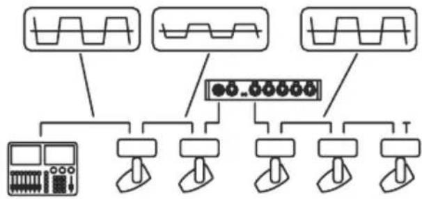
Martin Splitters amplify the DMX or DMX/RDM signal, allowing the data link to be extended by max. 500 m (1740 ft.) using AWG 22 DMX cable or 300 m (1000 ft.) using AWG 24 DMX cable:

flowchart
graph TD
    A["Input Waveform 1"] --> C["Device"]
    B["Input Waveform 2"] --> C
    D["Input Waveform 3"] --> C
    E["Output Device"] --> F["Load"]
without Splitter with Splitter
flowchart
graph TD
    A["Input Signal 1"] --> D["Display Unit"]
    B["Input Signal 2"] --> D
    C["Input Signal 3"] --> D
    E["Input Signal 4"] --> D
    F["Output Terminal 1"] --> D
    G["Output Terminal 2"] --> D
    H["Output Terminal 3"] --> D
    I["Output Terminal 4"] --> D
Figure 2: Amplifying the data signal
Regeneration
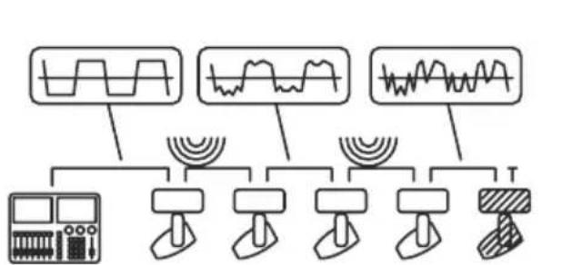
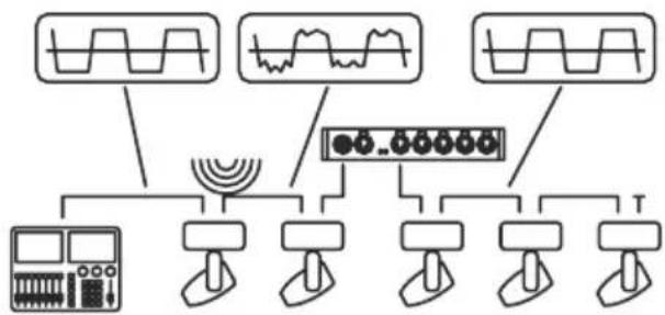
Martin Splitters clean and regenerate the data signal, removing the effects of disturbance:
flowchart
graph TD
    A["Waveform Display"] --> B["Input Device"]
    C["Waveform Display"] --> D["Output Signal"]
    E["Signal Waveform"] --> F["Output Signal"]
    G["Signal Waveform"] --> H["Output Signal"]
    I["Signal Waveform"] --> J["Output Signal"]
without Splitter with Splitter
flowchart
graph TD
    A["Input Signal"] --> B["Waveform Display"]
    C["Input Signal"] --> D["Waveform Display"]
    E["Input Signal"] --> F["Waveform Display"]
    G["Input Signal"] --> H["Display Unit"]
    I["Input Signal"] --> J["Display Unit"]
    K["Input Signal"] --> L["Display Unit"]
    M["Input Signal"] --> N["Display Unit"]
    O["Input Signal"] --> P["Display Unit"]
    Q["Input Signal"] --> R["Display Unit"]
    S["Input Signal"] --> T["Display Unit"]
    U["Input Signal"] --> V["Display Unit"]
    W["Input Signal"] --> X["Display Unit"]
    Y["Input Signal"] --> Z["Display Unit"]
Figure 3: Regenerating a corrupted signal
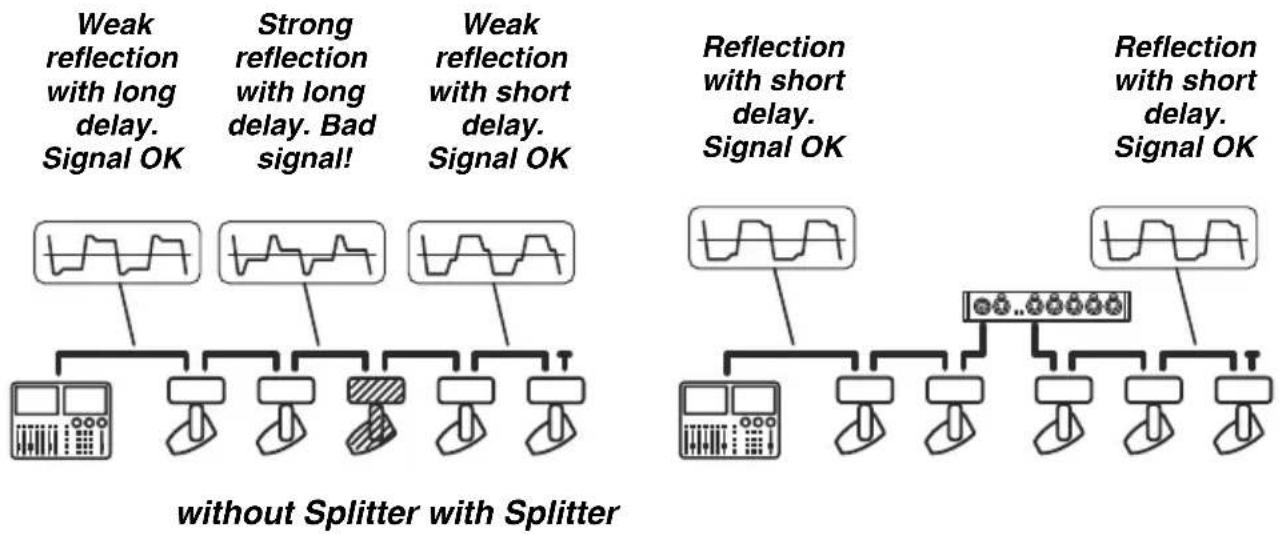
Martin Splitters also reduce signal reflections that can be a problem in larger installations or on longer cable lengths:
flowchart
graph TD
    A["Weak reflection with long delay. Signal OK"] --> B["Waveform"]
    C["Strong reflection with long delay. Bad signal!"] --> D["Waveform"]
    E["Weak reflection with short delay. Signal OK"] --> F["Waveform"]
    G["Reflection with short delay. Signal OK"] --> H["Waveform"]
    I["Reflection with short delay. Signal OK"] --> J["Waveform"]
    K["without Splitter with Splitter"] --> L["Waveform with Socks"]
    M["without Splitter with Splitter"] --> N["Waveform with Socks"]
    O["without Splitter with Splitter"] --> P["Waveform with Socks"]
Figure 4: Eliminating data signal reflections
Voltage surge protection
All five out sockets on Martin Splitters are optically isolated. This protects the Splitter, other branches of the data link and the controller from damage caused by any excess voltage on a branch downstream of the Splitter.

flowchart
graph TD
    A["with lightning bolt"] --> B["Control Panel"]
    C["with lightning bolt"] --> D["Control Panel"]
    E["with lightning bolt"] --> F["Control Panel"]
    G["with lightning bolt"] --> H["Control Panel"]
    I["with lightning bolt"] --> J["Control Panel"]
    K["with lightning bolt"] --> L["Control Panel"]
    M["with lightning bolt"] --> N["Control Panel"]
    O["with lightning bolt"] --> P["Control Panel"]
    Q["with lightning bolt"] --> R["Control Panel"]
    S["with lightning bolt"] --> T["Control Panel"]
    U["with lightning bolt"] --> V["Control Panel"]
    W["with lightning bolt"] --> X["Control Panel"]
Figure 5: Protecting against voltage surges
Physical installation
Mounting in a rig
Both the DMX 5.3 Splitter and the RDM 5.5 Splitter can be flown in a rig. To install them in a rig:
- Fasten a suitable rigging clamp for the truss or suspension bar to the Splitter with a minimum grade 8.8 M12 bolt as shown in Figure 6.
Warning! The bolt thread must protrude 10 mm (0.4 in.) minimum and 25 mm (0.9 in.) maximum into the Splitter when the bolt is tight.
-
Fasten the rigging clamp securely to a truss or suspension bar.
-
Loop a safety cable that is approved for the weight it will support through the eyelet in the back of the Splitter and around the truss or suspension bar.
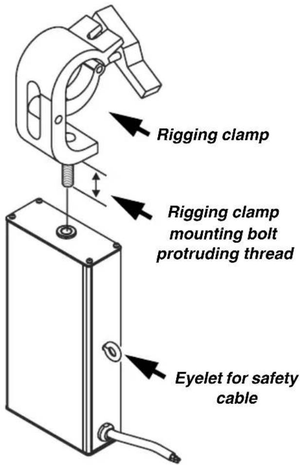
Figure 6: Mounting a rigging clamp
Fastening to a surface
Both the DMX 5.3 Splitter and the RDM 5.5 Splitter can be fastened to a flat, stable surface in any orientation. To fasten to a surface,
- Fasten the supplied L-brackets to the outer ends of the Splitter using the eight supplied Torx 10 M3 x 4 thread-forming screws as shown at A in Figure 7. The L-brackets can be fastened as shown at A or rotated through 180^ , allowing the Splitter to be fastened on or under a surface with four suitable screws.
Warning! Do not fasten screws with a thread length of more than 4 mm (0.15 in.) into the ends of either Splitter.
19-inch rack mounting
Both the DMX 5.3 Splitter and the RDM 5.5 Splitter can be mounted in pairs side-by-side in standard 19-inch racks. Both models have the same dimensions and mounting system. To mount in a rack:
-
Fasten two Splitters together side-by-side using the four Torx 10 M3 x 6 thread-forming attachment screws supplied with one of the Splitters as shown at B in Figure 7.
-
Fasten the L-brackets supplied with one of the Splitters to the outer ends of the pair of Splitters using the eight supplied thread-forming Torx 10 M3 x 4 screws as shown at C in Figure 7.
Warning! Do not fasten screws with a thread length of more than 4 mm (0.15 in.) into the ends of either Splitter.
- Use the L-brackets and suitable screws to fasten the Splitters into the rack.

Figure 7: Mounting options
AC power

Warning! For protection from dangerous electric shock, the device must be grounded (earthed). The local AC power source must have both overload and ground-fault (earth fault) protection.
Warning! Power socket outlets or external power switches used to supply the DMX 5.3 Splitter with power must be located near the device and easily accessible so that the device can easily be disconnected from power. In an emergency, the RDM 5.5 Splitter can be disconnected from power by removing the Neutrik PowerCon power input connector
Important! Only insert or remove a live Neutrik PowerCon connector to apply or cut power in an emergency, as doing so may cause arcing at the terminals that will damage the connectors.
AC operating range
The power supply units in both the DMX 5.3 Splitter and RDM 5.5 Splitter are fully auto-sensing and these devices can be connected to AC power at 100-240 V nominal at 50/60 Hz. Do not connect to power at any other voltage or frequency.
Power cable and plug
Martin DMX 5.3 Splitter
The 5.3 DMX Splitter is supplied with a hard-wired, EU color-coded power cable with a US-type AC mains power plug. If this plug is not suitable for your local power outlets, cut the plug off the end of the cable and either hard-wire the Splitter to the building's electrical installation providing an easily accessible power on/off switch close to the device, or replace it with a grounding-type (earthed) power plug that suits the local power outlets. Following the power plug manufacturer's instructions, connect the green/yellow wire to ground (earth), the blue wire to neutral, and the brown wire to live.
Table 1 shows some pin identification schemes. Consult a qualified electrician if you have any doubts about proper installation.
| Wire (US system) | Wire (EU system) | Pin Marking Screw color | |
| black brown | live “L” yellow or brass | ||
| white blue | neutral “N” silver | ||
| green yellow | /green ground |  | green |
Table 1: Power plug pin identification
Martin RDM 5.5 Splitter
The RDM 5.5 Splitter is supplied with a blue Neutrik PowerCon NAC3FCA cable-mount connector for power input. The user must supply a suitable length of power cable that meets the requirements listed on page 5 and install the PowerCon connector on it as described below. The user must then either hard-wire the power cable to the building's electrical installation, providing an easily accessible power on/off switch close to the device, or install on the power cable a grounding-type (earthed) mains plug that is suitable for the local power outlets, following the power plug manufacturer's instructions. Table 1 shows some pin identification schemes. Consult a qualified electrician if you have any doubts about proper installation.
Installing a Neutrik NAC3FCA power connector on a power cable

To install a Neutrik NAC3FCA input connector on a power cable:
- Slide the bushing over the cable.
-
Slide the white chuck over cables with a diameter ( D_a ) of 5 - 10 mm (0.2 - 0.4 in.), or the black chuck over cables with a diameter of 10 - 15 mm (0.4 - 0.6 in.).
-
Prepare the end of the cable by stripping 20 mm (0.8 in.) of the cable's outer jacket.
-
Strip 8 mm (1/3 in.) from the end of each of the wires.
![20.00 mm [0.787°] 8.00 mm [0.315°] Da Cable end](/content/2026/05/934406/images/d3097716bc8c0631e6b50ff529326655cf61b5ade926be4f994d816e9d88bbe2.jpg)
-
Insert each of the wire ends into the appropriate terminal (see illustration on right and Table 1 above) and fasten using a small flathead screwdriver.
-
Push and insert the chuck into the housing (note that there is a raised key on the chuck to ensure that it is oriented correctly).
-
Fasten the bushing using a wrench to a torque of 2.5 Nm (1.8 lb.-ft).
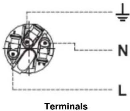
Illustrations in this section used by kind permission of Neutrik AG.
Relaying power to other devices

Warning! The current load of all devices connected to AC mains power in one interconnected chain via the RDM 5.5 Splitter's power throughput outlet must not exceed 19.6 amps.
Devices can be linked in a chain, power throughput to power input, so that they all draw AC mains power via the RDM 5.5 Splitter's Neutrik PowerCon power throughput socket, but certain points must be respected:
- Power cable that meets the requirements specified on page 5 of this manual must be used to connect the RDM 5.5 Splitter to AC mains power and to connect all the devices in the chain to each other.
- A light-grey Neutrik PowerCon NAC3FCB cable-mount connector must be used to draw AC mains power from the RDM 5.5 Splitter's power throughput socket and a blue Neutrik PowerCon NAC3FCA cable-mount connector must be used to supply power at the RDM 5.5 Splitter's power input socket.
- No matter what the AC mains power voltage is, the current draw of all the devices that draw AC mains power in one interconnected chain from the power throughput socket of an RDM 5.5 Splitter that is connected directly to AC power must not exceed 19.6 amps total.
Data connections and setup
The Martin DMX 5.3 Splitter uses 3-pin XLR and the Martin RDM 5.5 Splitter uses 5-pin XLR sockets for all data connections: in, optically isolated, optically isolated, thru and out.
Pins 4 and 5 in 5-pin XLR connectors are not used by DMX or RDM signals, but if you intend to use pins 4 and 5 in the RDM 5.5 Splitter's 5-pin sockets for any other purpose, note that these pins are connected from the in to the thru socket, but that there is no connection to pins 4 and 5 of the out sockets.
Data input
Connect the data link cable from the controller to the in socket on the Splitter using a female XLR cable connector.
Data throughput
The main data link daisy-chain can be continued at the thru socket using a male XLR cable connector. The signal that is relayed from the in to the thru socket is not amplified or processed in any way and is available even if the Splitter is not powered.
DMX termination
The DMX termination button (see Figure 8) on the front of the Splitter must be:
- pressed in to activate termination if you do not connect devices to the thru socket, and
- not pressed in if you continue the data link from the thru socket.
The LED under the termination button lights when DMX termination is applied.
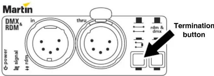
Figure 8: DMX termination (5.5 Splitter illustrated)
Data output
The Splitter's out 1 - out 5 sockets provide five amplified, buffered, regenerated and optically isolated outputs of the data signal present at the in socket.
You can create up to 5 branches on the data link by connecting DMX cable to the Splitter's out sockets using XLR male cable connectors. Each branch can have up to 32 devices connected and must be terminated at the end of the branch by inserting a DMX termination plug in the last device's DMX output. Unused outputs on the Splitter do not need to be terminated.
RDM (Martin RDM 5.5 Splitter)
The Martin RDM 5.5 Splitter relays both DMX and bidirectional RDM signals on the data link.
Removing non-DMX signals
All Martin DMX-controlled products monitor the data signal and filter out any data that they are not designed to accept. Martin products that do not support RDM will therefore not be disturbed if an RDM signal is present on the data link. However, there are DMX-controlled products in use that do not filter the data signal. These products may behave unexpectedly if they receive an RDM signal.
To solve this problem, the RDM 5.5 Splitter can be used as a data signal filter. If the dmx only button is pressed in, the RDM 5.5 Splitter will remove all data signals apart from DMX from the five out sockets. Note that pressing in the dmx only button will not affect the thru socket, which will continue to relay unmodified data signals from the in socket.

Figure 9: DMX only
If your installation contains a mixture of (a) devices that use or are unaffected by RDM and (b) devices that are disturbed by RDM, use separate Splitters to send DMX/RDM to the devices in group (a) and to send only DMX to the devices in group (b).
Operation
Status LEDs
Operation can be monitored using the status LEDs on the front of the Martin Splitters:
Martin DMX 5.3 Splitter
| G-power | The power LED lights if AC mains power is applied and the Splitter's power supply unit is working. |
| Signal | The signal LED on the front panel lights green if a valid data signal is present at the in socket. |
| q_err | The err (error) LED lights red if a signal present at the in socket is faulty. |
| The LED under the termination button lights if the Splitter's internal DMX termination is activated. |
Martin RDM 5.5 Splitter
| G-power | The power LED lights if AC mains power is applied and the Splitter's power supply unit is working. |
| Jn signal | The signal LED on the front panel lights green if a valid signal is present at the in socket and red if a faulty signal is present at the in socket. |
| rdm | The rdm LED lights if an RDM signal is present. |
| The LED under the termination button lights if the Splitter's internal DMX termination is activated. | |
| dmx only | The LED under the dmx only button lights if the DMX-only filter is active (i.e. all non-DMX signals are removed from outputs 1 - 5). |
| ^2 Jn | The signal LED next to outputs 1 - 5 lights if a valid DMX or RDM signal is present at that output socket. |
Firmware/software uploads when using Splitters
Martin products that support firmware/software uploads in .MU3 file format over the data link should accept uploads without problem when a DMX 5.3 or RDM 5.5 Splitter is present on the data link. When using an RDM 5.5 Splitter, make sure that the dmx only button is not pressed in during firmware uploads.
RDM and the RDM 5.5 Splitter
From 2011, information on RDM and Martin products that support it is being added to the Martin website at www.martin.com
Service

Warning! There are no user-serviceable parts inside the device. Refer all service apart from cleaning to Martin Professional or its authorized service agents.
Installation, on-site service and maintenance can be provided worldwide by the Martin Professional Global Service organization and its approved agents, giving owners access to Martin's expertise and product knowledge in a partnership that will ensure the highest level of performance throughout the product's lifetime. Please contact your Martin supplier for details.
The only service operations the user can carry out on a Martin DMX 5.3 or RDM 5.5 Splitter are occasional cleaning and uploading firmware to the Splitter.
Cleaning
Do not use abrasive, caustic or solvent-based products for cleaning, as they can damage plastic or painted surfaces. Do not splash the device with water or any other liquid.
To clean the device:
- Disconnect the device from power and allow it to cool for at least 5 minutes.
- Clean the outside of the device with a soft cloth slightly dampened in a warm water/detergent solution.
Installing Splitter firmware
Firmware (main CPU software) can be uploaded to a Splitter if you suspect that the device has a software-related fault or if a newer version of the firmware becomes available. Firmware updates are available from the Martin website and can be installed in one Splitter at a time with a PC and USB/DMX interface.
The following are required in order to install firmware:
- The latest version of the Splitter firmware, available for download free of charge from the Product Support area of the Martin website at www.martin.com
-
The Windows-based Martin Uploader application, available for download free of charge from the Downloads area of the Martin website.
-
A PC running a Windows version supported by the Martin Uploader application.
- A Martin USB Duo™ DMX Interface Box (P/N 90703010) with its supplied cables.
Firmware upload procedure
To install firmware in a Splitter:
- Start the Martin Uploader application on a PC connected to the Internet and download the splitter firmware from within the Uploader application.
- Connect the PC to a Martin USB Duo™ DMX interface box and connect the interface box to the Splitter's data in connector.
- Upload the firmware as described in the Uploader's help file or user documentation.
- Disconnect the PC and interface box and reconnect the Splitter to the DMX link.
- Cycle the Splitter's power off and on and check that the Splitter operates correctly. If a firmware upload seems to have been unsuccessful, cycle power off and on again and check for correct operation. If there still seems to be a problem, repeat the firmware upload procedure.
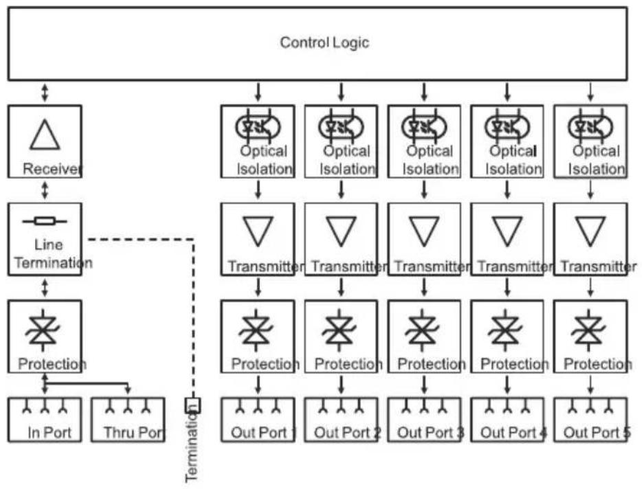
Block diagrams
Martin DMX 5.3 Splitter
flowchart
graph TD
    A["Control Logic"] --> B["Receiver"]
    A --> C["Optical Isolation"]
    A --> D["Optical Isolation"]
    A --> E["Optical Isolation"]
    A --> F["Optical Isolation"]
    B --> G["Line Termination"]
    C --> H["Transmitter"]
    D --> I["Transmitter"]
    E --> J["Transmitter"]
    F --> K["Transmitter"]
    G --> L["Protection"]
    H --> M["Protection"]
    I --> N["Protection"]
    J --> O["Protection"]
    K --> P["Protection"]
    L --> Q["In Port"]
    M --> R["Thru Port"]
    N --> S["Out Port 1"]
    O --> T["Out Port 2"]
    P --> U["Out Port 3"]
    Q --> V["Out Port 4"]
    R --> W["Out Port 5"]
    S --> X["Termination"]
    T --> X
    U --> X
    V --> X
Martin RDM 5.5 Splitter

flowchart
graph TD
    A["Control Logic"] --> B["Line Termination"]
    A --> C["Protection"]
    B --> D["In Port"]
    B --> E["Thru Port"]
    C --> F["Out Port 1"]
    C --> G["Out Port 2"]
    C --> H["Out Port 3"]
    C --> I["Out Port 4"]
    C --> J["Out Port 5"]
    C --> K["Optical Isolation"]
    C --> L["Tranceiver"]
    C --> M["Protection"]
    C --> N["Optical Isolation"]
    C --> O["Tranceiver"]
    C --> P["Protection"]
    C --> Q["Optical Isolation"]
    C --> R["Tranceiver"]
    C --> S["Optical Isolation"]
    C --> T["Optical Isolation"]
    C --> U["Optical Isolation"]
    C --> V["Optical Isolation"]
    C --> W["Optical Isolation"]
    C --> X["Optical Isolation"]
    C --> Y["Optical Isolation"]
    C --> Z["Optical Isolation"]
    C --> AA["Optical Isolation"]
    C --> AB["Optical Isolation"]
    C --> AC["Optical Isolation"]
    C --> AD["Optical Isolation"]
    C --> AE["Optical Isolation"]
    C --> AF["Optical Isolation"]
    C --> AG["Optical Isolation"]
    C --> AH["Optical Isolation"]
    C --> AI["Optical Isolation"]
    C --> AJ["Optical Isolation"]
    C --> AK["Optical Isolation"]
    C --> AL["Optical Isolation"]
    C --> AM["Optical Isolation"]
    C --> AN["Optical Isolation"]
    C --> AO["Optical Isolation"]
    C --> AP["Optical Isolation"]
    C --> AQ["Optical Isolation"]
    C --> AR["Optical Isolation"]
    C --> AS["Optical Isolation"]
    C --> AT["Optical Isolation"]
    C --> AU["Optical Isolation"]
    C --> AV["Optical Isolation"]
    C --> AW["Optical Isolation"]
    C --> AX["Optical Isolation"]
    C --> AY["Optical Isolation"]
    C --> AZ["Optical Isolation"]
    C --> BA["Optical Isolation"]
    C --> BB["Optical Isolation"]
    C --> BC["Optical Isolation"]
    C --> BD["Optical Isolation"]
    C --> BE["Optical Isolation"]
    C --> BF["Optical Isolation"]
    C --> BG["Optical Isolation"]
    C --> BH["Optical Isolation"]
    C --> BI["Optical Isolation"]
    C --> BJ["Optical Isolation"]
    C --> BK["Optical Isolation"]
    C --> BL["Optical Isolation"]
    C --> BM["Optical Isolation"]
    C --> BN["Optical Isolation"]
    C --> BO["Optical Isolation"]
    C --> BP["Optical Isolation"]
    C --> BQ["Optical Isolation"]
Specifications
Physical
Depth 125 mm (4.9 in.)
Width 220 mm (8.7 in.)
Height 45 mm (1.8 in.)
Weight 0.9 kg (2 lb.)
Data signal
DMX (all models) ANSI E1.11 (USITT DMX 512-A)
RDM (Martin RDM 5.5 Splitter).... ANSI E1.20
Electrical standard ....EIA-485
Data cable type. ........ Shielded twisted pair
Data cable gauge 22 or 24 AWG
Data cable impedance 120 Ohms
Maximum length per branch, 22 AWG cable ..... 500 m (1640 ft)
Maximum length per branch, 24 AWG cable .... 300 m (1000 ft)
Maximum load per branch 32 devices
Construction
Housing …… Aluminum
Finish .... Electrostatic powder coating
Connections
Martin DMX 5.3 Splitter
AC power input .... Hard-wired cable with US mains plug
DMX in 3-pin male XLR
DMX thru (unprocessed).... 3-pin locking female XLR
DMX out (processed*) .5 x 3-pin locking female XLR
Martin RDM 5.5 Splitter
AC power input..... Neutrik PowerCon NAC3MPA input socket (blue)
AC power throughput ..... Neutrik PowerCon NAC3MPB output socket (grey)
DMX in and RDM controller .... 5-pin locking male XLR
DMX thru and RDM devices (unprocessed) ..... 5-pin locking female XLR
DMX out and RDM devices (processed*) .....5 x 5-pin locking female XLR
*Processed data signals are amplified, regenerated, buffered and optically isolated
Electrical
AC power 100 - 240 V nominal, 50/60 Hz
Power supply unit .... Switch mode, auto-sensing
Typical power consumption
110 V, 60 Hz. 4 W
240 V, 50 Hz. 4 W
Measurements made at nominal voltage. Allow for a deviation of +/- 10%.
Thermal
Minimum ambient temperature ( T_a min.) -30^ C ( -22^ F)
Maximum ambient temperature ( T_a max.) 55°C (137°F)
Approvals

EU safety....EN 60950-1
EU EMC.... EN 55022, EN 55024
EN 55103-1, EN 55103-2
US safety (pending) .....UL 508
US EMC .... FCC Part 15 Class A
Canadian safety (pending) CAN/CSA C22.2 No. 14
Canadian EMC. . . . . . . . . . . . ICES-003 Class A
Australia/New Zealand.....C-TICK N4241
Included items
Martin DMX 5.3 Splitter
DMX splitter device
1.2 m (3.9 ft.) hard-wired power cable with US (NEMA-5-15) plug
4 x screws to join two devices for rack mounting
2 x L-brackets + 8 x screws for 19-inch rack mounting two side-by-side units (1U)
User manual
Martin RDM 5.5 Splitter
DMX/RDM splitter device
1 x Neutrik PowerCon cable connector, power input, blue (NAC 3 FCA)
4 x screws to join two devices for rack mounting
2 x L-brackets + 8 x screws for 19-inch rack mounting two side-by-side units (1U)
User manual
Accessories
Neutrik PowerCon NAC3FCA power input cable connector, blue . P/N 05342804
Neutrik PowerCon NAC3FCB power output cable connector, grey P/N 05342805
Half-coupler clamp P/N 91602005
G-clamp P/N 91602003
Quick-trigger clamp. P/N 91602007
Safety wire, safe working load 50 kg P/N 91604003
Adapter, 3-pin male - 5-pin female XLR, straight through ..... P/N 11820004
Adapter, 5-pin male - 3-pin female XLR, straight through ..... P/N 11820005
Adapter, 5-pin male XLR to RJ-45 plug, 15 cm P/N 11840111
Adapter, 5-pin female XLR to RJ-45 plug, 15 cm . . . . . . . . . . . . P/N 11840112
Ordering information
Martin DMX 5.3 Splitter....P/N 90758140
Martin RDM 5.5 Splitter P/N 90758150

natural_image
Simple line drawing of a trash bin with crossed lines indicating no waste or discharge (no text or symbols)Disposing of this product
Martin Professional products are supplied in compliance with Directive 2002/96/EC of the European Parliament and of the Council of the European Union on WEEE (Waste Electrical and Electronic Equipment), as amended by Directive 2003/108/EC, where applicable.
Help preserve the environment! Ensure that this product is recycled at the end of its life. Your supplier can give details of local arrangements for the disposal of Martin products.
- Martin DMX 5.3 Splitter™ Martin RDM 5.5 Splitter™
- Dimensions
- Contents
- Dimensions 2
- Safety information 4
- Introduction 7
- Physical installation ....11
- AC power 13
- Data connections and setup 16
- Operation 19
- Service 21
- Block diagrams .....23
- Specifications 24
- Safety information
- PROTECTION FROM ELECTRIC SHOCK
- PROTECTION FROM BURNS AND FIRE
- PROTECTION FROM INJURY DUE TO FALLS
- Introduction
- Features
- Unpacking
- Using for the first time
- Functionality
- Splitting the data link
- Amplification
- Regeneration
- Voltage surge protection
- Physical installation
- Mounting in a rig
- Fastening to a surface
- 19-inch rack mounting
- AC power
- AC operating range
- Power cable and plug
- Martin DMX 5.3 Splitter
- Martin RDM 5.5 Splitter
- Relaying power to other devices
- Data connections and setup
- Data input
- Data throughput
- DMX termination
- Data output
- RDM (Martin RDM 5.5 Splitter)
- Removing non-DMX signals
- Operation
- Status LEDs
- Firmware/software uploads when using Splitters
- RDM and the RDM 5.5 Splitter
- Service
- Cleaning
- Installing Splitter firmware
- Firmware upload procedure
- Block diagrams
- Specifications
- Physical
- Data signal
- Construction
- Connections
- Electrical
- Typical power consumption
- Thermal
- Approvals
- Included items
- Accessories
- Ordering information
- Disposing of this product
Brand : MARTIN
Model : DMX 5.3 Splitter
Category : Audio/video converter