
Quadnic - Synthesizer Studio Electronics - Free user manual and instructions
Find the device manual for free Quadnic Studio Electronics in PDF.


| Product Type | Modular Analog Synthesizer System |
| Brand | Studio Electronics |
| Model | Quadnic |
| Total HP (Seito Rising configuration) | 106 HP |
| Case Dimensions (external with lid) | 11.5 x 22.5 x 8 inches (292 x 572 x 203 mm) |
| Power Supply | +/-12V DC, 3.5A per rail; +5V 500mA per row |
| Power Connections per Row | 15 Doepfer compatible (shrouded and keyed) |
| Mounting System | Sliding nuts |
| Included Modules (Seito Rising) | MIDI 3, Multiple (x2), Oscillation (x2), 4075 Filter, Levels, Sci-Fi, Shapers, Amp, LFO2, Outs |
| Filter Types Available | 5089 (Minimoog-style), 4075 (ARP-style), 3003 (TB-303-style), SEM (Oberheim-style), SE88 (CS-80-style) |
| Amplifier Type | 2-stage Class A discrete VCA with Drive and Drone controls |
| Oscillator Module | Class-A discrete, DC-coupled, with waveform mixing (sine, tri, saw, square, sub) |
| Envelope Generators | Dual ADSR with short/long range, invertible output |
| LFO Module | Dual analog LFO with triangle, square, and shape control |
| Output Module | Stereo headphone amp and dual mono line outs |
| MIDI Interface | MIDI 3 module: pitch CV, gate, velocity, clock, arpeggiator |
| Maintenance | Keep dry; avoid dust; power off before connecting/disconnecting ribbon cables |
| Safety | Do not remove modules while powered; ensure proper ribbon cable orientation (-12V stripe) |
| Warranty | 1 year limited (USA); register online |
| Country of Manufacture | USA (modules except LFO2, Outs, MIDI3) |
| Spare Parts & Repair | Contact support@studioelectronics.com; RMA required |
Frequently Asked Questions - Quadnic Studio Electronics
User questions about Quadnic Studio Electronics
0 question about this device. Answer the ones you know or ask your own.
Ask a new question about this device
Download the instructions for your Synthesizer in PDF format for free! Find your manual Quadnic - Studio Electronics and take your electronic device back in hand. On this page are published all the documents necessary for the use of your device. Quadnic by Studio Electronics.
USER MANUAL Quadnic Studio Electronics
Please read the Boomstar Modular Synthesizer Manual completely before use, and retain for future reference.
IMPORTANT Ribbon Cable Power Information:
Boomstar Modular combines a set of individual modules to create a complete instrument. The individual modules can be rearranged, removed, and replaced with any compatible eurorack modules from Studio Electronics and other manufacturers.
Boomstar Modular uses a standard eurorack power rail to connect the modules to the internal bipolar +/-12v power supply. Please pay very close attention to the orientation of the ribbon cable when adding and removing modules. The stripe on the ribbon cable marks -12v . This stripe needs to line up with the -12v pins on the power rail and the -12v pins on the module. Failure to match up the pins correctly can result in damage to one or all the modules in the Boomstar Modular. On the power rail, the -12v pins are clearly labeled. On the individual modules, the positive and negative sides of the pin connectors are labeled next to the power header on either the top or bottom of the PCB.
Do NOT remove individual modules from the Boomstar while synthesizer is plugged in.
NEVER unplug ribbon cables from the Boomstar Modular, or any other modules while the Boomstar Modular is plugged in.
Table of Contents
Box Contents 1
Dimensions & Power Specifications 2-3
Boomstar Modular Introduction 4
Modular Signal Paths 5
Complete MODSTAR Systems 6-11
Individual Modules 12-39
1 Year Limited Warranty 40-41
Support & Contact 42
Box Contents
Module of choice
1x Ribbon Cable
1x Information Card
BOOMSTAR MODULAR MODSTAR
DIMENSIONS & POWER SPECIFICATIONS

Filters
5089 - Size: 12hp
Module depth with ribbon cable attached: 39.7mm
+12 / -12 Power Usage: 40mA, 28mA
4075 - Size: 12hp
Module depth with ribbon cable attached: 39.7mm
+12 / -12 Power Usage: 23mA, 30mA
3003 - Size: 12hp
Module depth with ribbon cable attached: 39.7mm
+12 / -12 Power Usage: 37mA, 25mA
SEM - Size: 12hp
Module depth with ribbon cable attached: 39.7mm
+12 / -12 Power Usage: 23mA, 23mA
SE88 - Size: 20hp
Module depth with ribbon cable attached: 39.7mm
+12 / -12 Power Usage: ?mA, ?mA
Amplifier
AMP - Size: 8hp
Module depth with ribbon cable attached: 39.7mm
36mA, 12mA (+12 / -12)
Analog Oscillator
OSCILLATION - Size: 48hp
Module depth with ribbon cable attached: 39.7mm
44mA, 39mA (+12 / ·12)
Multiple
Mult - Size: 2hp
20mm with ribbon cable attached, passive
DIMENSIONS & POWER SPECIFICATIONS
Mixer
LEVELS - Size: 10hp
Module depth with ribbon cable attached:
39.7mm
22mA (+12 / -12)
Ringmod, Sample & Hold, Noise
SCI FI - Size: 10hp
Module depth with ribbon cable attached:
39.7mm
+12 / -12 Power Usage: ?mA, ?mA
Envelope
SHAPERS - Size: 12hp
Module depth with ribbon cable attached:
39.7mm
+12 / -12 Power Usage: ?mA, ?mA
Modulation
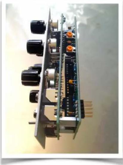
LFO2 - Size: 6hp
Module depth with ribbon cable attached:
35mm
30mA
Final Output
OUTS - Size: 6hp
Module depth with ribbon cable attached:
43mm
30mA
Boomstar Modular Introduction
THE BOOMSTAR MODULAR SYSTEM realizes the seemingly inevitable eurorack sprawl of our semi-modular BOOMSTAR desktop synth, consisting of 14 modules that dramatically open up the root level programming and sound sculpting of that lush, potent, and fantastically flexible multi-filtered Boomstar sound.
What makes it tick: Let's tick 'em off: Class A 5089, 3003 and AMP *, rugged through-hole construction, discrete circuitry, hand-matched transistors in the filters and amplifier, multi-filtered, hand-crafted, Premium Quality Analog sound. We'd like to think we've learned a few things bringing the MIDIMINI, SE1-X, ATC-X, polyphonic CODE OMEGA synths, MODMAX PEDALS, C2S, PRE 2, and SLATE PRO AUDIO DRAGON and FOX to market, and the air waves worldwide.
Our Boomstar Modular System's (Modstar) 5089 circuit mirrors faithfully the filter design from the Minimoog—it is not a style; it's not a type, not reminiscent of, not vintage inspired—it is the analog sound standard manufactured anew, and how we love it so. Apply the same thinking to our 4075, 3003, and SE80 filters vis-à-vis their originals, and you've caught our drift; the OSCILLATION and AMP modules also resonate with the Mini's timeless designs, functionality, and gorgeous, gleaming sound—modernized and reimagined by the maestro Tim Caswell himself, but we're just getting started here; the SEM filter is on deck.
We hope you are as thrilled with your purchase of the complete system/individual modules, as we are with our partnership with the exceedingly savvy folks at PITTSBURGH MODULAR, and the final highly collaborative through-hole designs which flowed from the first Nicol/St. Regis Beer Summit at Winter NAMM '13, and culminated in total design integration with STUDIO ELECTRONICS Tim Caswell and Greg St. Regis. All MODSTAR modules (excepting Pittsburgh's brilliant MIDI3, LFO2, and Outs) are manufactured to SE's highest standards of legendary build quality right here in the U. S. A. Take away Pittsburgh's invaluable, real world/walking the streets of Euroland insights, experience, and deep resources—this project would have long since have faded to grey. A tip of the SE chapeau to Richard Nicol, Perry, and the full-strength, generally less-weathered outfit at PGH. AND to sales guru Geoff Farr who both hounded and inspired: "When are the euro modules going to be ready?" Looks.
* See pg.17, par. 2 for caveat.
4


Modular Signal Paths
(Copy courtesy of Pittsburgh Modular)
The BOOMSTAR MODULAR'S signal path is divided into two types of signals: audio signals and control voltages.
The audio signal is the sound that is produced. The audio signal path starts at a sound source such as a Waveforms oscillator, LFO running at audio rate, or the Filter in oscillator mode. The audio signal is then patched through other modules used to shape the sound such as mixers, filters, and amplifiers.
Control voltages (CV) manipulate the audio signal in several different ways.
Gates are represented by a high or low control voltage. A gate can be generated using a square or pulse wave from an oscillator or LFO, or by using a gate output from an external sequencer, or MIDI keyboard. A gate can be shaped using an envelope generator to control the attack, decay, sustain, and release of the gate. The modified gate signal can then be sent to any CV input on the synth.
A second use for control voltages is as a modulation source. For example, a control voltage from the SCI-FI S/H OUT (Sample and Hold) module patched into the 1V/O input on an OSCILLATION module controls the frequency of the oscillator based on the randomly generated sequence of notes, additionally, the OSCILLATION module's full range oscillators make perfect control voltage modulation sources; and audio signals make excellent control voltage source for oscillator FM (frequency modulation). Understanding exactly how it works can sometimes hinder creativity—experiment!
MODSTAR SEITO RISING

Modstar Seito Rising 106 hp: MIDI 3 6hp, M (Multiple) 2hp, Oscillation (x2) 32hp, 4075 12hp, M 2hp, Levels 10hp, Sci-Fi 10hp, Shapers 12hp, Amp 8hp, LFO 2 6hp, Outs 6hp. Housed in a sleek and sturdy, carbon-fibre black MONOROCKET M6E case - a superbly well powered and constructed Eurorack enclosure. *
Seito Rising Specifications
- MIDI 3: Third generation extremely full-featured MIDI to CV converter
- MULTIPLE: (x2) Passive utility module with two independent sections of four linked jacks—splits signals into three copies
- OSCILLATION: (x2) Class-A, discrete, DC coupled, output buffered, exponential current source, vintage-designed analog oscillator
- 4075: Arp-flavored Discrete, voltage controlled, 24/db/oct cascaded transconductance low-pass filter—six pairs of hand-matched transistors—Really a 4-pole ARP 4072 (better: more parts and trims)
-
LEVELS: Versatile, low-noise six channel summing mixer/attenuator for audio and CV—pots are wired with logarithmic volume curves
-
SCI FI: Ring Mod, White and Pink Noise, Sample and Hold "Classic Synth Toolbox," with LFO and slewing control of S&H
- SHAPERS: Dual four stage envelope generator with independently adjustable ATTACK, DECAY, SUSTAIN, and RELEASE stages
- AMP: 2 stage Class A discrete design, using 3 pairs of hand matched transistors; Drive—'70s era distortion and Drone control
- LFO2: Potent all analog dual LFO module—two different low frequency oscillator circuits provide a variety of modulation options
- OUTS: Dual independent output module featuring a stereo 1/4" headphone amplifier output and dual mono 1/4" line level outputs
M6104 Specifications
M6104 TECHNICAL DETAILS
Dimensions:
2 rows / 106hp each
Internal depth 4.5 inches (except area over PSU which is 2 7/8)
External Dimensions with lid attached (H x W x D): 11.5 x 22.5 x 8
Unit stands vertical or lays on its back
Stackable if you detach the handle (4 pan head screws)
Power:
3.5a on the +/-12v rails
500ma of +5v per row installed
15 Doepfer compatible power connections per row (shrouded and keyed)
5 Analogue Solutions power connections per row
Internally mounted 120v and 240v Power Supply Unit - includes IEC power cable
Hardware:
"Sliding Nuts" mounting system - includes mounting screws

MODSTAR SENSEI ANALOG

Sensei Analog Specifications
MODSTAR SENSEI ANALOG 212hp Top Row: OSCILLATION (x3) 48hp, MULTIPLE 2hp, SEM 12hp, 4075 12hp, 5089 12hp, SE88 20hp; Bottom Row: BRAND PLATE 6hp, MIDI 3 6hp, MULT 2hp, LEVELS 10hp, SHAPERS 12hp, AMP 8hp, LFO2 6hp, MULT 2hp, SCI FI 10hp, MULT 2hp, LEVELS 10hp, SHAPERS 12hp, AMP 8hp, LFO2 6hp, OUTS 6hp. Housed in a sleek 'n sturdy, "carbon fibre" black MONOROCKET M6104: a superbly well powered and constructed Eurorack enclosure, ensuring gorgeous sound, deep dependability, and rugged portability. *
- OSCILLATION: Class-A, discrete, DC coupled, output buffered, exponential current source, vintage-designed analog oscillator
- SEM: Obi-flavored, 12 Db voltage controlled state variable filter and "Pendulum Chaos Generator"—damping/stabilizing override feature
- 4075: Arp-flavored Discrete, voltage controlled, 24/db/oct cascaded transconductance low-pass filter—six pairs of hand-matched transistors—Really a 4-pole ARP 4072 (better: more parts and trims)
- 5089: Mini-flavored voltage controlled, discrete analog, 24 db/oct transistor ladder, low-pass filter (hand-matched transistors)
- SE88: Dual mode: High Pass/Band Reject, Low Pass/BandPass dual resonant, 12Db CS80 filter with stereo "Pendulum Chaos Generation"
-
MIDI 3: Third generation extremely full-featured MIDI to CV converter
-
LEVELS: Versatile, low-noise six channel summing mixer/attenuator for audio and CV—pots are wired with logarithmic volume curves
- SHAPERS: Dual four stage envelope generator with independently adjustable ATTACK, DECAY, SUSTAIN, and RELEASE stages
- AMP: 2 stage Class A discrete design, using 3 pairs of hand matched transistors; Drive—‘70s era distortion and Drone control
- LFO2: Potent all analog dual LFO module—two different low frequency oscillator circuits provide a variety of modulation options
- SCI FI: Ring Mod, White and Pink Noise, Sample and Hold "Classic Synth Toolbox," with LFO and slewing control of S&H
- OUTS: Dual independent output module featuring a stereo 1/4" headphone amplifier output and dual mono 1/4" line level outputs
M6104 Specifications
M6104 TECHNICAL DETAILS
Dimensions:
2 rows / 106hp each
Internal depth 4.5 inches (except area over PSU which is 2 7/8)
External Dimensions with lid attached (H x W x D): 11.5 x 22.5 x 8
Unit stands vertical or lays on its back
Stackable if you detach the handle (4 pan head screws)
Power:
3.5a on the +/-12v rails
500ma of +5v per row installed
15 Doepfer compatible power connections per row (shrouded and keyed)
5 Analogue Solutions power connections per row
Internally mounted 120v and 240v Power Supply Unit - includes IEC power cable
Hardware:
"Sliding Nuts" mounting system - includes mounting screws

5089 Filter Module
Description
The 5089 filter is a voltage controlled, discrete analog, 24 db/oct transistor ladder, low-pass filter, employing hand-matched transistors. Our ladder low-pass filter—a subtractive analog sound synthesis foundation—in its lowest FREQUENCY setting removes, or cuts off higher frequency harmonics; its RESONANCE or Q circuit emphasizes those harmonics to the point of "squealy," giddy self-oscillation, tracking the keyboard in its FULL setting quite nicely if seeking an alternative sine wave.
Our 5089 has the roundest, slickest tone of all the Boomstar's filters. Go easy on it, and round, creamy buttery flavors wrap the oscillators in earthy warmth; smash it and a meaty, satisfying overdrive, and a maximum harvest of vintage 1960s and 1970s organic-sounding, second-order harmonic distortion fill the plate. Every setting is balanced and bountiful. Looking for traditional R'n B baselines and leads? Focus here on the rich saturation of this benchmark filter and its symmetrical cascades of generation-stretching timbres. All BOOMSTAR MODULAR filters are hand-built in the U.S. Pick-and-Place all the way!
Potentiometer Potential
Three attenuverter and four attenuation pots control the FREQUENCY, RESONANCE, FREQ CV 1, RESO CV, FREQ CV 2, INPUT and OUTPUT, delivering smooth, detailed, and complex expression.
Switch It Up
Classic Minimoog FULL and HALF strength filter frequency keyboard/voltage tracking for rounder low end with brilliant highs.
Patch It Up
Seven patch points: 1 V/O, FREQ CV 1, FREQ CV 2, RESO CV, INPUT and 2x OUTPUT direct the deepest manipulation.

5089 Filter Module - 2
All Controls and Patch Points (arranged in order of visual flow)
FREQUENCY – Adjusts the frequency, or cut-off of the filter.
RESONANCE – Adjusts the resonance, or "Q" of the filter. *
FULL HALF TRACK – Switch between full and half keyboard/voltage tracking.
FREQ CV 1 - Frequency control voltage 1 input attenuverter.
RESO CV – Resonance control voltage input attenuverter.
FREQ CV 2 - Frequency control voltage 2 input attenuverter.
INPUT – Adjusts the audio input.
OUTPUT – Adjusts the audio output.
1 V/O - One volt per octave control voltage input.
FREQ CV 1 - Frequency control voltage 1 input.
FREQ CV 2 - Frequency control voltage 2 input—get tricky with the second attempt.
RESO CV – Resonance control voltage input—use for shimmers or howling wolf tones.
INPUT - Audio input.
2x OUTPUT - Audio outputs.
* From 7:00 (0) to 9:00 our "Negative Resonance Saturation" adds beefiness, boosting the waveform amplitude and taming waveform transients (most pronounced in the 3003 filter): set to 9:00 to achieve the cleanest tone possible.

4075 Filter Module
Description
The 4075 filter is a voltage controlled, discrete analog, 24/db/oct cascaded transconductance low-pass filter, employing hand-matched transistors. In its lowest FREQUENCY setting it shaves off higher frequency harmonics; its RESONANCE or "Q" circuit pushes those harmonics past the self-oscillation boiling point, projecting a thumpy, thrashing squeal, with explosive low to mid-range power and depth. The design is actually pulled from the four-pole ARP 4072 (better: more parts and trims), sans the 12kHz design flaw which hamstrung the original's high end. The 4075 name has stuck—no correcting our little misnomer.
Our 4075 filter is the most requested of the Boomstar filter models, perhaps owing to its uniqueness. Has there ever been a better match for a square wave? It weaves dreams with "glidey," 70s basslines, is a natural in the lead department, and feels as if a temper tantrum simmers a mere micron beneath its veneer of faux respectability. Aggressive and articulate, this fresh ARP can snap punishing kick drum sounds out as well as color with bright, edgy, stringy tones for essential arpeggiations.
Potentiometer Potential
Three attenuverter and four attenuation pots control the FREQUENCY, RESONANCE, FREQ CV 1, RESO CV, FREQ CV 2, INPUT and OUTPUT, delivering smooth, detailed, and complex expression.
Switch It Up
Classic Minimoog FULL and HALF strength filter frequency keyboard/voltage tracking for rounder low end with brilliant highs.
Patch It Up
Seven patch points: 1 V/O, FREQ CV 1, FREQ CV 2, RESO CV, INPUT and 2x OUTPUT direct the deepest manipulation.

4075 Filter Module - 2
All Controls and Patch Points (arranged in order of visual flow)
FREQUENCY – Adjusts the frequency, or cut-off of the filter.
RESONANCE – Adjusts the resonance, or "Q" of the filter. *
FULL HALF TRACK – Switch between full and half keyboard/voltage tracking.
FREQ CV 1 - Frequency control voltage 1 input attenuverter.
RESO CV – Resonance control voltage input attenuverter.
FREQ CV 2 - Frequency control voltage 2 input attenuverter.
INPUT – Adjusts the audio input.
OUTPUT – Adjusts the audio output.
1 V/O - One volt per octave control voltage input.
FREQ CV 1 - Frequency control voltage 1 input.
FREQ CV 2 - Frequency control voltage 2 input—get tricky with the second attempt.
RESO CV – Resonance control voltage input—use for shimmers or howling wolf tones.
INPUT - Audio input.
2x OUTPUT - Audio outputs.
* From 7:00 (0) to 9:00 our "Negative Resonance Saturation" adds beefiness, boosting the waveform amplitude and taming waveform transients (most pronounced in the 3003 filter): set to 9:00 to achieve the cleanest tone possible.

3003 Filter Module
Description
The 3003 filter is a voltage controlled, discrete analog 18 db/oct ladder low-pass filter, employing hand-matched transistors. Drop the FREQUENCY knob to 0 and things get pretty dull; swing it back up and those "Transistor Bass" highs come crashing through the gate. The 3003's RESONANCE circuit at max will sing out more than the TB's signature chirping in a fun, bubbly, if washy, poorer relation, Mini "clone-ish" way; use it tastefully, or throw moderation to the wind for overwhelming chirp force.
Our 3003 filter has the most gentle sonic touch of its partners in the Boomstar fold, but nevertheless is quite capable of shaping precise, very dynamic tone. Whether or not this STUDIO ELECTRONICS filter is filling its traditional baseline boxing niche, driving a harsh, liquid, acid-like tone, a softer more rubber-bandy SH-101-ish presence, or out of the bass range altogether, leading the way, all is within easy reach of this surprisingly warm and versatile VCF. The 3003 can be distinctly vocal at times, especially when one is willing to put grittier, more distorted desires aside.
Potentiometer Potential
Three attenuverter and four attenuation pots control the FREQUENCY, RESONANCE, FREQ CV 1, RESO CV, FREQ CV 2, INPUT and OUTPUT, delivering smooth, detailed, and complex expression.
Switch It Up
Classic Minimoog FULL and HALF strength filter frequency keyboard/voltage tracking for rounder low end with brilliant highs.
Patch It Up
Seven patch points: 1 V/O, FREQ CV 1, FREQ CV 2, RESO CV, INPUT and 2x OUTPUT direct the deepest manipulation.

3003 Filter Module - 2
All Controls and Patch Points (arranged in order of visual flow)
FREQUENCY – Adjusts the frequency, or cut-off of the filter.
RESONANCE – Adjusts the resonance of the filter. *
FULL HALF TRACK – Switch between full and half keyboard/voltage tracking.
FREQ CV 1 - Frequency control voltage 1 input attenuverter.
RESO CV – Resonance control voltage input attenuverter.
FREQ CV 2 - Frequency control voltage 2 input attenuverter.
INPUT – Adjusts the audio input.
OUTPUT – Adjusts the audio output.
1 V/O - One volt per octave control voltage input.
FREQ CV 1 - Frequency control voltage 1 input.
FREQ CV 2 - Frequency control voltage 2 input—get tricky with the second attempt.
RESO CV – Resonance control voltage input—use for shimmers or howling wolf tones.
INPUT - Audio input.
2x OUTPUT - Audio outputs.
* From 7:00 (0) to 9:00 our "Negative Resonance Saturation" adds beefiness, boosting the waveform amplitude and taming waveform transients (most pronounced in this 3003 filter): set to 9:00 to achieve the cleanest tone possible.

AMP Module
Description
From Designer Tim Caswell's own hand: The amplifier (AMP) is a 2 stage Class A discrete design using three pairs of hand matched transistors. Envelope is usually applied to ST1 CV1; ST1 CV2 goes thru an attenuverter and can be used for envelope or modulation; ST2 CV1 goes to the 2nd stage, and is typically used for volume control; ST2 CV2 goes thru an attenuverter providing access to the final stage of modulation input.
The AMP, the 5089, and the 3003 are Class A circuits. They draw more current from the +12 rail than from the -12 volt rail. If the system power supply is under-sized, hum or buzz may be heard. In that case, larger filter capacitors and/or a larger power transformer will be needed. The 4075 draws equally from both rails, and is more immune to hum. Like our time-tested filters, this Boomstar Modular AMP module, a gorgeous all-in-one discrete VCA charmer, is hand-built entirely in the U. S. of A—just ask Rachael Herbison!
Potentiometer Potential
Two attenuverter, and two attenuation pots control the INPUT, ST1 CV2 (CV), ST2 CV2 (CV), and OUTPUT.
Switch It Up
Uber-useful continuous hypnotic DRONE for endless sustain/release, and DRIVE—the overdrive circuit from the Boomstar desktop—for last stage push, clipping, good ol' dirty vintage fuzz fun, and tone-crushed distortion.

AMP Module - 2
Patch It Up
Six patch points: INPUT, ST1 CV1, ST1 CV2, ST2 CV1, ST2 CV2, OUTPUT direct the deepest manipulation.
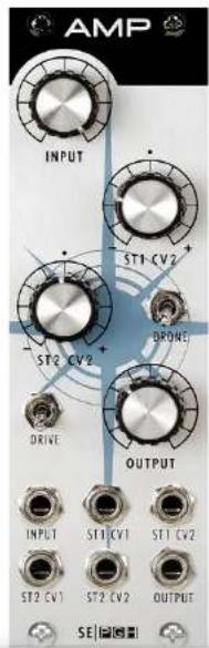
All Controls and Patch Points (arranged in order of visual flow)
INPUT – Adjusts the audio input.
ST1 CV2 (formerly STAGE 1/2) – Adjusts stage 1, control voltage 2 (CV).
ST2 CV2 (formerly STAGE 2/2) – Adjusts stage 2, control voltage 2 (CV).
DRONE – Sustains the last note received—“Hold that Train.”
DRIVE – Final output stage saturation/overdrive—absolutely smash the input, and back down the output level for classic guitar amp "master volume" crunch savagery, and last gasp volume control if so inspired.
OUTPUT – Adjusts the audio output.
INPUT - Audio input.
ST1 CV1 (formerly ST 1/1) – Stage 1, control voltage 1 input (CV).
ST1 CV2 (formerly ST 1/2) – Stage 1, control voltage 2 input (CV).
ST2 CV1 (formerly ST 2/1) – Stage 2, control voltage 1 input (CV).
ST2 CV2 (formerly ST 2/2) – Stage 2, control voltage 2 input (CV).
OUTPUT – Audio output.
SEM Filter Module
Description
Sensei Caswell: "Our SEM is known as a "Voltage Controlled State Variable Filter" because it provides simultaneous high pass, low pass, and band pass outputs, all with a 12 dB/oct slope. The notch is the inverse of the bandpass, achieved by summing the Low Pass and high pass outputs. This version is a combination of the original SEM filter and the newer design from the OBX, along with improvements by Studio Electronics. It has a modest current draw, which it pulls evenly from the plus and minus rails."
If you've heard the SEM filter in our Boomstar desktop (https://soundcloud.com/studio-electronics/sets/mean-sem-ranch/) you also know that this 12 dB favorite is "... capable of lighter, more subtle tones than the other three models. This isn't to suggest the filter's Low Pass mode can't cater for fat and punchy, because it can." · Paul Nagle, Sound on Sound. Deeply gratifying tonal variance and this emotional warmth https://soundcloud.com/alanc3-1/switched-on-sem—our friend Fred Falke's favorite—can reach into your head and heart, and stay as long as desired. Thank you Lord Tom Oberheim for this marvelous design/template from which we were able to work our very own Studio Electronics eurorack filter enchantments.
Potentiometer Potential
Three attenuverter and four attenuation pots control the FREQUENCY, RESONANCE, FREQ CV 1, RESO CV, LP HP, INPUT and OUTPUT, delivering smooth, detailed, and ever variable expression.
Switch It Up
FULL and HALF strength filter frequency keyboard/voltage tracking, and BP / LP-HP modes.

SEM Filter Module - 2
Patch It Up
Seven patch points: 1 V/O, FREQ CV 1, FREQ CV 2, RESO CV, INPUT, BP, LP-HP, and OUTPUT jack you in.
All Controls and Patch Points (arranged in order of visual flow)
FREQUENCY – Adjusts the frequency, or cut-off of the filter.
RESONANCE – Adjusts the resonance of the filter. *
FULL HALF TRACK – Switch between full and half keyboard/voltage tracking.
FREQ CV 1 - Frequency control voltage 1 input attenuverter.
RESO CV – Resonance control voltage input attenuverter.
FREQ CV 2 - Frequency control voltage 2 input attenuverter.
INPUT – Adjusts the audio input.
OUTPUT – Adjusts the audio output.
1 V/O - One volt per octave control voltage input.
FREQ CV 1 - Frequency control voltage 1 input.
BP OUT – Band Pass Output. No cable patched, BP passes through the mains.
RESO CV – Resonance control voltage input—use for shimmers or howling wolf tones.
LP HP - Low Pass / High Pass attenuverter.
INPUT – Audio input.

SEM Filter Module - 3
OUTPUT – Audio output.
* From 7:00 (0) to 9:00 our "Negative Resonance Saturation" adds beefiness, boosting the waveform amplitude and taming waveform transients (most pronounced in this 3003 filter): set to 9:00 to achieve the cleanest tone possible.
BYSIB (Before You Send It Back)
This filter (and the SE88) can be 'input driven' to the cutout/cutoff/blackout point, for angry, aggressive unpredictability, and staggered, shell-shocked recovery. We wanted it that way; it's perfectly harmless OpAmp smashing, for smashing good fun. Think traumatic movie scene after which an actor's hearing momentarily disappears (extreme wooziness overtakes the balance of his senses—and camera work), high-pitched sounds follow, and then blessed normalcy of awareness and sensory perception gradually, grudgingly return. That. No reboot necessary: just sweep the frequency forward and back, and pull back the input level, unless of course you want "that" to keep happening. Taunting the edge is entertaining too.

OSCILLATION Module
Description
Tim Caswell unplugged: "Another hybrid, utilizing an exponential current source similar the ones from ARP and Oberheim, followed by wave shaping circuits adapted from the 2nd generation MiniMoog oscillator board, and incorporating waveform mixing circuits pioneered by SE. This provides a large variety of tones that would otherwise require several patch cords and an external mixer. With a two oscillator system, that's 9 or 10 patch cords and an 8 input mixer. Modest current draw, evenly from plus and minus."
TC continuing: "What's nice about our OSCILLATION stunner is that "the waveforms are DC-coupled [components connected directly together without coupling capacitors], so they keep their shape even at sub-Hz speeds. The outputs are also buffered, so the amplitude is independent of the load they are driving. The waveform levels on some modern eurorack OSCs are often all different, and they vary depending if they go into the mixer or directly to the filter!" Coupling the circuitry without capacitors in-line allows the full spectrum of sound frequencies to pass through.
Potentiometer Potential
Three attenuverter and four attenuation pots control the FREQUENCY, TUNE, PW CV IN, PUSLE WIDTH, FM CV IN, and SUB LEVEL for smooth, detailed, and complex expression, and sweeping expression.
Switch It Up
NORMAL and LOW RANGE - wide sweeping audio frequencies, or clicks (respectively) for creating a rhythmic pulse or sweep; SINE, TRI, SAW, SQR - your friendly neighborhood waveform on and offs.

OSCILLATION Module - 2
Patch It Up
Six patch points: INPUT, ST1 CV1, ST1 CV2, ST2 CV1, ST2 CV2, OUTPUT direct the deepest manipulation.
All Controls and Patch Points (arranged in order of visual flow)
INPUT FREQUENCY – Oscillator frequency attenuator.
NORMAL / LOW RANGE - Oscillator domain switch.
TUNE – Oscillator fine-tune attenuverter.
PULSE WIDTH - Variable pulse wave width control.
SINE – Sine wave on/off.
TRI - Triangle wave on/off.
SAW – Sawtooth wave on/off.
SQR - Square (pulse) wave on/off.
FM CV IN - Frequency Modulation control voltage input attenuverter.
SUB LEVEL – Sub (one octave down) level attenuator.
1 V/O - One volt per octave control voltage input.
FM IN – Frequency Modulation control voltage input.
SYNC IN – Oscillator Sync control voltage input.
PW IN – Pulse Width control voltage input.

OSCILLATION Module - 3
SUB OUT – Sub Oscillator output.
SINE OUT – Sine Oscillator output.
TRI OUT - Triangle wave output.
SAW OUT - Sawtooth wave output.
RAMP OUT – Ramp (reverse sawtooth) wave output.
SQR OUT - Square wave output.

SE88 Filter Module
Description
Our version of the boxy, Blade Runner-sweet and Boomstar-brash dual-mode CS80 filter, initially married to the Omega Series Synths, and then tucked-into the 'Stars, it now joins the 3u Modstar Collective. We've twisted and turned the SE88 to unflatten the earth, so to speak: the original CS-80 fed an HP filter into a LP filter, but with our CS80 homage, one can select MODE 1's HP or BP to feed MODE 2's LP or BP, or patch it to reverse path and flow. The audio signal is completely controllable with input / output levels for each filter; respect and cherish your filter's input gain stages, for a smooth yet often brassy sound—shed your mercy, to strike hard for boiling, snarling bite and bark, even to the blackout/cutout point; then and only then, uniquely blend wildly divergent mode settings for the filter family values you revere.
To get things merrily modulating, each filter employs attenuverters for frequency and resonance experimentation and decimation. While the SE88 does not self- oscillate, we did amp up the resonance level for full-throttle squelching. A master attenuverter-controlled FM (frequency modulation) level can feed and fight both filters simultaneously, and tracking switches individualize the keyboard control response for oftentimes contrasting, and homogeneous filter modes.
Potentiometer Potential
Five attenuverter and eight attenuation pots: FREQUENCY MODE 1, FM IN, FREQUENCY MODE 2, RESONANCE (M1), M1 FM, RESONANCE (M2), M1 RES CV, M2 RES CV, OUTPUT, M2 FM, OUTPUT Along bottom patch point row: LEVEL (M1), LEVEL (M2).

SE88 Filter Module - 2
Switch It Up
2/3 · 1/3 TRACK, FULL/HALF TRACK, HP/BP (High-Pass/Band-Pass), LP/BP (Low-Pass/Band-Pass).
Patch It Up
Ten patch points: 1 V/O, FM IN, M1 FM, M2 FM, M1 RES CV, M2 RES CV, M1 IN, M1 OUT, M2 IN, M2 OUT.
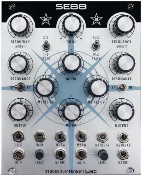
All Controls and Patch Points (arranged in order of visual flow)
FREQUENCY MODE 1 - Mode 1 filter frequency attenuator.
2/3 - 1/3 TRACK – Mode 1 keyboard control of frequency.
FM IN – Master frequency modulation attenuverter.
FULL - HALF TRACK – Mode 2 keyboard control of frequency.
FREQUENCY MODE 2 - Mode 2 filter frequency attenuator.
RESONANCE - Mode 1 resonance, or "Q" attenuator. *
M1 FM - Mode 1 frequency modulation attenuverter.
RESONANCE - Mode 2 resonance, or "Q" attenuator. *
HP/BP - Mode 1 High-Pass/Band-Pass switch.
M1 RES CV - Mode 1 resonance control voltage attenuverter.
M2 RES CV - Mode 2 resonance control voltage attenuverter.
SE88 Filter Module - 3
LP/BP - Mode 2 Low-Pass/Band-Pass switch.
OUTPUT - Mode 1 audio attenuator.
M2 FM - Mode 2 frequency modulation attenuverter.
OUTPUT - Mode 2 audio attenuator.
1 V/O - One volt per octave control voltage input.
FM IN – Frequency modulation control voltage input.
M1 FM - Mode 1 frequency modulation input.
M2 FM - Mode 2 frequency modulation input.
M1 RES CV - Mode 1 resonance control voltage input.
M2 RES CV - Mode 2 resonance control voltage input.
M1 IN - Mode 1 audio input.
LEVEL – Mode 1 audio input attenuator.
M1 OUT - Mode 1 audio output.
M2 IN - Mode 2 audio input.
LEVEL - Mode 2 audio input attenuator.
M2 OUT - Mode 2 audio output.
* From 7:00 (0) to 9:00 our "Negative Resonance Saturation" adds beefiness, boosting the waveform amplitude and taming waveform transients (most pronounced in the 3003 filter): set to 9:00 to achieve the cleanest tone possible.

SE88 Filter Module - 4
BYSIB (Before You Send It Back)
This filter (and the SEM) can be 'input driven' to the cutout/cutoff/blackout point, for angry, aggressive unpredictability, and staggered, shell-shocked recovery. We wanted it that way; it's perfectly harmless OpAmp smashing, for smashing good fun. Think traumatic movie scene after which an actor's hearing momentarily disappears (extreme wooziness overtakes the balance of his senses—and camera work), high-pitched sounds follow, and then blessed normalcy of awareness and sensory perception gradually, grudgingly return. That. No reboot necessary: just sweep the frequency forward and back, and pull back the input level, unless of course you want "that" to keep happening. Taunting the edge is entertaining too.

Mult Module
Description
A passive utility module with two independent sections of four linked jacks. Each section of the Multiple module splits an incoming signal into three copies. This allows one audio or CV signal to be sent to several destinations at once.

Levels Module
Description
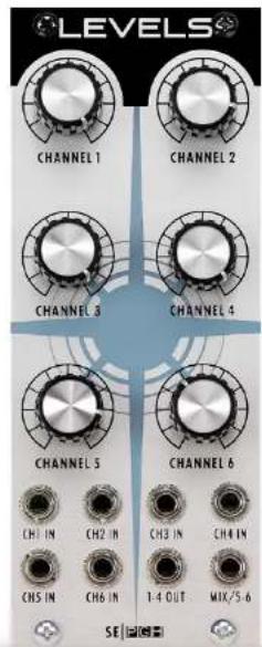
LEVELS is a versatile, low-noise six channel summing mixer/attenuator for audio and CV, which can be used rather effectively in a variety of ways: 6 in 1 out, or two separate mixers: 4 in 1 out, and 2 in 1 out, e. g., when only jacked-in to MIX 5/6 output all input channels pass through; utilizing the 1-4 OUT removes channels 1-4 from the MIX 5/6 output. Handy indeed.
The pots are wired with a logarithmic volume curve that is tuned for use with audio but it will work splendidly with CV as well. Pressing LEVELS into service as a wave-shaper by patching all of the individual OSCILLATION waveform outs (sub, sine, tri, saw, ramp, square) into channel inputs 1-6, makes for vivid beguiling shapes—a continuously morphable hybrid waveform of your innermost sound designs. Consider pairing these two Modstar pieces when building your system.
Potentiometer Potential
Six attenuation pots control the CHANNEL 1, CHANNEL 2, CHANNEL 3, CHANNEL 4, CHANNEL 5, and CHANNEL 6.
Patch It Up
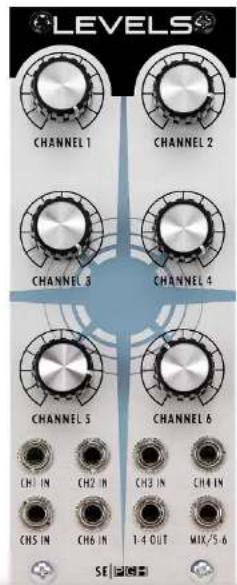
Eight patch points: CH1 IN, CH 2 IN, CH 3 IN, CH 4 IN, CH 5 IN, CH 6 IN, 1-4 OUT, MIX/5-6.
Levels Module - 2
All Controls and Patch Points (arranged in order of visual flow)
CHANNEL 1 - Adjusts the level or value of 1.
CHANNEL 2 - Adjusts the level or value of 2.
CHANNEL 3 – Adjusts the level or value of 3.
CHANNEL 4 – Adjusts the level or value of 4.
CHANNEL 5 – Adjusts the level or value of 5.
CHANNEL 6 - Adjusts the level or value of 6.
CH 1 IN - Channel 1 input.
CH 2 IN - Channel 2 input.
CH 3 IN - Channel 3 input.
CH 4 IN - Channel 4 input.
CH 5 IN - Channel 5 input.
CH 6 IN - Channel 6 input.
1-4 OUT - Channels 1-4 output.
MIX/5-6 - All channels output (MIX), or 5-6 when cable is plugged into any of the 1-4 channel inputs.
Sci Fi Module
Description
Th SCI FI is an ingeniously vintage-circuit-inspired Richard Nicol/Pittsburgh Modular original. As the reader might already know, ring modulation is a signal-processing electronic function: an implementation of amplitude modulation or frequency mixing, performed by multiplying two signals. This beloved other-worldly, warm, and at times clangorous coloring dates at least as far back to Bode's Melochord of 1947, technology which was ultimately licensed to Robert Moog in the early 1960s.
Back at the Modstar Ranch: The SCI FI's outputted ring-modulated signal is the sum and difference of the frequencies present in each waveform—a signal rich in partials—often producing a haunting, bell-like, metallic, and sometimes softly grinding, understated modulation awash in harmonic and non-harmonic tones. S.E. brought its own brand of dynamic ModMax Pedal-flavored Ringmod to the world in 2002.
SCI FI is getting better all the time with its companion LFO FREQ (low frequency oscillator), true analog PINK, and digital WHITE noise, S & H—a true sample and hold generator, with RANGE control, and LAG generator—a slew limiter which craftily smooths out changes in audio or modulation signals: higher values = smoother signal flowing. This module is every bit as creamy sounding as it is electrically charged: the higher frequencies coat the sound with a sparkling quality one wouldn't naturally expect.
Potentiometer Potential
Six attenuation pots: RING MOD, LFO FREQ, WHITE, PINK, RANGE, and LAG.
Switch It Up
Seven patch points: RM X IN, RM Y IN, GATE, SOURCE, RM OUT, WHITE, PINK, and S & H OUT.

Sci Fi Module - 2
Patch It Up
Eight patch points: RM X IN, RM Y IN, GATE, SOURCE, RM OUT, WHITE, PINK, S & H OUT.
All Controls and Patch Points (arranged in order of visual flow)
RING MOD – Adjusts the ring mod depth.
LFO FREQ – Adjusts the rate of the sample & hold.
WHITE – Adjusts the white noise level.
PINK – Adjusts the pink noise level.
RANGE – Adjusts the sample & hold depth or intensity.
LAG – Adjusts the sample and hold lag or slew limiting (glide): in the circuit after the sample & hold, before the range attenuator.
RM X IN - Ring Mod X waveform input.
RM Y IN - Ring Mod Y waveform input.
GATE – External gate input for sample & hold.
SOURCE – External audio input for sample & hold.
RM OUT - Ring Mod output.
WHITE – White noise output.
PINK – Pink noise output—the pink noise is normaled to the source input of the sample & hold.
S & H OUT – Sample & hold output.

Shapers Module
Description
Shapers is a dual four stage envelope generator with independently adjustable ATTACK, DECAY, SUSTAIN, and RELEASE stages. Our Pittsburgh Modular hybrid ADSR smooths the shape of the incoming gates and triggers to produce a more expressive instrument, just like its antecedent. The ADSR output can be used to control the amplitude of an oscillator, the cutoff frequency of a filter or any other function on a module that accepts control voltages.
The functionality of Shapers is easy enough to grock: the incoming gate or trigger signal passes through each of the four stages to output an envelope. When the ADSR module receives a gate or trigger signal, the ATTACK determines the amount of time needed for the envelope generator to reach the peak output voltage and move on to the decay stage. DECAY sets the amount of time needed to transition to the level set by the sustain knob. The SUSTAIN level is maintained as long as the incoming gate remains on or high. Once the incoming gate goes low or off, the release stage takes over. The RELEASE knob sets the time needed to close the envelope and return the ADSR output to 0 volts.
Shapers ENVs. can respond lightening fast or demonstrate the patience of a saint, especially in the LONG RANGE 1 and 2 settings. INV 1 makes topsy-turvy time fun with the inverting of the ADSR 1, and the LED indicators provide a useful visual assist.
Potentiometer Potential
Eight attenuation pots control the ATTACK (x2), DECAY (x2), SUSTAIN (x2), RELEASE (x2), contour and detour.
Switch It Up
SHORT and LONG range time settings for both ADSRs make dramatic scene changes near instant.

Shapers Module - 2
Patch It Up
Five patch points: IN 1, OUT 1, INV 1, IN 2, and OUT 2 connect and direct.
All Controls and Patch Points (arranged in order of visual flow)
ATTACK (x2) - Adjusts the attack stage.
DECAY (x2) · Adjusts the decay stage.
SUSTAIN (x2) - Adjust the sustain stage.
RELEASE (x2) · Adjusts the release stage.
SHORT / LONG RANGE 1 - Selects the envelope range for ADSR 1.
SHORT / LONG RANGE 2 - Selects the envelope range for ADSR 2.
IN 1 - Control voltage input 1.
OUT 1 - Control voltage output 1.
INV 1 - Inverted control voltage output 1.
IN 2 - Control voltage input 2.
OUT 2 - Control voltage output 2.

LFO2
Description
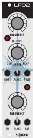
LFO2 is a dual low frequency, basic LFO module which uses two different types of low frequency oscillator circuits to provide a variety of modulation options, not the least of which is a near glacial speed at the lowest rate setting.
LFO 1 is a triangle based low frequency oscillator that utilizes rate and symmetry controls to generate shifting waveforms. Adjusting the symmetry control varies the shape of the TRI output from sawtooth to triangle to ramp, and also adjusts the pulse width of the SQR wave output.
LFO 2 is a simple triangle based low frequency oscillator with rate control over the triangle and square outputs.
Module Controls
LFO 1 (Top)
Rate Knob
Shape Knob: TRI · Saw / Triangle / Ramp Wave Output
Range Switch - Switches the frequency range of LFO 1.
SQR - Square / Pulse Wave Output
LFO 2 (Bottom)
Rate Knob
TRI - Triangle Wave Output
Range Switch - Switches the frequency range of LFO 2.
SQR - Square Wave Output
Outs Module
Description
OUTS: The simplest way to get sound out of a modular—so our good friends at PGH tell us. OUTS is a dual independent output module featuring a high quality opAmp, a stereo 1/4" headphone amplifier output with level control (STEREO TRS), and dual mono 1/4" line level outputs (LEFT, RIGHT).
Patch only the LEFT input and its strapped to both the LEFT and RIGHT outputs. Handy.

MIDI 3 Module
Description
The MIDI 3 is Pittsburgh Modular's third generation extremely full-featured MIDI to CV converter. It includes a complete set of mono and duophonic midi response modes, assignable CC and dedicated velocity outputs, a feature rich clock source with tap tempo, midi and external gate clock dividers, and multiple arpeggiator responses. This module is deep.
A MIDI to CV module converts standard midi note messages into the analog control voltages used by modular and other analog synthesizers. This allows the synthesizer to be controlled by a midi keyboard, sequencer, or DAW. The two CV outputs on the MIDI 3 can be used to control the pitch of an oscillator, cutoff frequency of a filter, or any other function that requires a control voltage signal. The set of Gate outputs on the MIDI 3 can be used to trigger envelope generators or other modules expecting a gate or clock source.
Pittsburgh Modular's MIDI 3 Manual
Please refer to the brilliant manufacturer's manual to attain full operational awareness (FOA).
![MIDI3 GATE 1 CY 1 [MIDI CH] GATE 2 CY 2 [P BEND] CC VELOCITY [CC #] TAP CLOCK [CLOCK] MONO DUD ARP MODE EDIT HOLD + - MIDI IN SE](/content/2026/05/933482/images/7d0523fac9b3772bff9cea8993f52e3861c6f3845260482870a09265fb5e9025.jpg)
Limited Warranty
LIMITED WARRANTY TERMS AND CONDITIONS
This Limited Warranty applies only to ANALOGIA INC./STUDIO ELECTRONICS purchased in the United States of America. Outside the USA, warranty policy and service is determined by the laws of the country of purchase and followed by our local authorized distributor. A listing of our authorized distributors is available at http://www.studioelectronics.com/shop/distributors/
ANALOGIA INC./STUDIO ELECTRONICS warrants to the first owner of a covered product purchased directly from ANALOGIA INC./STUDIO ELECTRONICS, or an authorized ANALOGIA INC./STUDIO ELECTRONICS dealer in the U.S., that this product will be free from defects in materials and or workmanship for a period of one year from the date of purchase. Please register this product online at http://studioelectronics.com/support/registration/ to establish the date of purchase (NOT A REQUIREMENT FOR WARRANTY SERVICE BUT A GOOD IDEA).
To exercise your rights under this Warranty as the first owner/purchaser, YOU MUST SHIP THIS PRODUCT IN ITS ORIGINAL PACKAGING (which we can replace and send to you for \$10) at your expense, with proof of purchase documentation and the ANALOGIA INC./STUDIO ELECTRONICS supplied power adapter, to ANALOGIA INC. An RMA (Return Material Authorization) number from ANALOGIA INC./STUDIO ELECTRONICS must be obtained first before returning any product. Email RMA requests to rma@studioelectronics.com, or call us at (310) 640-3546 to secure an RMA #. Products shipped to ANALOGIA INC. without an RMA will be refused and returned. Shipping insurance is optional, but highly recommended.
ANALOGIA INC./STUDIO ELECTRONICS will repair or replace this product at its sole option and at no charge to you for parts and labor—when deemed necessary and within the warranty period—provided that ANALOGIA INC./STUDIO ELECTRONICS reserves the right to determine whether the product is “defective” for purposes of this Limited Warranty. This Warranty does not apply if damage to this product occurs as a result of abuse or misuse, abnormal use or handling, improper packaging, another product’s interaction, exposure to temperature extremes, or if the product has been altered or modified/customized in any way, or the damage was caused by unauthorized repair or service. The original product must return to ANALOGIA INC. unaltered.
Limited Warranty - 2
IN NO EVENT SHALL ANALOGIA INC./STUDIO ELECTRONICS BE LIABLE FOR ANY INDIRECT, INCIDENTAL, COLLATERAL, EXEMPLARY, PUNITIVE, CONSEQUENTIAL OR SPECIAL DAMAGES OR LOSSES ARISING OUT OF YOUR PURCHASE OF PRODUCTS AND/OR OUT OF THIS WARRANTY, INCLUDING WITHOUT LIMITATION, LOSS OF USE, PROFITS, GOODWILL OR SAVINGS OR LOSS OF DATA, MUSIC, ELECTRONIC FILES, OR PREFERENCES THAT MAY HAVE BEEN STORED BY A USER OF THE PRODUCT, EVEN IF ANALOGIA INC./ STUDIO ELECTRONICS HAS BEEN ADVISED OF THE POSSIBILITY OF SUCH DAMAGES OR CLAIMS. SOME STATES DO NOT ALLOW THE EXCLUSION OR LIMITATION OF INCIDENTAL, PUNITIVE, OR CONSEQUENTIAL DAMAGES, SO THE ABOVE LIMITATION OR EXCLUSION MAY NOT APPLY TO YOU.
This Limited Warranty and the right of replacement is in lieu of any and all other warranties—which you hereby waive—and it gives U.S. purchasers specific legal rights. You may also have other rights which vary from State to State.
ANALOGIA INC., 530 West Palm Ave. El Segundo, CA 90245
support@studioelectronics.com
ANALOGIA INC. - Ardent Proprietors of STUDIO ELECTRONICS
Tel: (310) 640-3546 • Web: www.studioelectronics.com • General Delivery email: support@studioelectronics.com facebook.com/StudioElectronics • twitter.com/SE BoomStar • youtube.com/user/StudioElectronics • soundcloud.com/studio-electronics


- IMPORTANT RIBBON CABLE POWER INFORMATION
- TABLE OF CONTENTS
- BOX CONTENTS
- BOOMSTAR MODULAR MODSTAR
- DIMENSIONS & POWER SPECIFICATIONS
- FILTERS
- AMPLIFIER
- ANALOG OSCILLATOR
- MULTIPLE
- MIXER
- RINGMOD, SAMPLE & HOLD, NOISE
- ENVELOPE
- MODULATION
- FINAL OUTPUT
- BOOMSTAR MODULAR INTRODUCTION
- MODULAR SIGNAL PATHS
- SEITO RISING SPECIFICATIONS
- M6104 SPECIFICATIONS
- M6104 TECHNICAL DETAILS
- DIMENSIONS
- POWER
- HARDWARE
- SENSEI ANALOG SPECIFICATIONS
- 5089 FILTER MODULE
- DESCRIPTION
- POTENTIOMETER POTENTIAL
- SWITCH IT UP
- PATCH IT UP
- 5089 FILTER MODULE - 2
- ALL CONTROLS AND PATCH POINTS (ARRANGED IN ORDER OF VISUAL FLOW)
- 4075 FILTER MODULE
- 4075 FILTER MODULE - 2
- 3003 FILTER MODULE
- 3003 FILTER MODULE - 2
- AMP MODULE
- AMP MODULE - 2
- SEM FILTER MODULE
- SEM FILTER MODULE - 2
- SEM FILTER MODULE - 3
- BYSIB (BEFORE YOU SEND IT BACK)
- OSCILLATION MODULE
- OSCILLATION MODULE - 2
- OSCILLATION MODULE - 3
- SE88 FILTER MODULE
- SE88 FILTER MODULE - 2
- SE88 FILTER MODULE - 3
- SE88 FILTER MODULE - 4
- MULT MODULE
- LEVELS MODULE
- LEVELS MODULE - 2
- SCI FI MODULE
- SCI FI MODULE - 2
- SHAPERS MODULE
- SHAPERS MODULE - 2
- LFO2
- MODULE CONTROLS
- OUTS MODULE
- MIDI 3 MODULE
- PITTSBURGH MODULAR'S MIDI 3 MANUAL
- LIMITED WARRANTY
- LIMITED WARRANTY TERMS AND CONDITIONS
- LIMITED WARRANTY - 2
- ANALOGIA INC. - ARDENT PROPRIETORS OF STUDIO ELECTRONICS
Brand : Studio Electronics
Model : Quadnic
Category : Synthesizer