
Boomstar Modular VCA2 - Synthesizer Studio Electronics - Free user manual and instructions
Find the device manual for free Boomstar Modular VCA2 Studio Electronics in PDF.


| Product Type | Semi-Modular Synthesizer Module |
| Brand | Studio Electronics |
| Model | Boomstar Modular VCA2 |
| Form Factor | Eurorack compatible, 16 HP |
| Dimensions (Width x Height x Depth) | 3.5" x 5.06" x 1.5" (88.9 x 128.5 x 38.1 mm) |
| Weight | 0.5 lbs (227 g) |
| Power Supply | +12V DC, 100 mA via Eurorack power header |
| Power Consumption | 1.2 W typical |
| Main Function | Voltage Controlled Amplifier with 2 channels and modulation inputs |
| Audio Inputs | 2x 1/4" TS unbalanced, impedance 100kΩ |
| Audio Outputs | 2x 1/4" TS unbalanced, impedance 1kΩ |
| CV Inputs | 2x 3.5mm TS, 0-5V range |
| Frequency Response | 20 Hz - 20 kHz ±0.5 dB |
| Total Harmonic Distortion | < 0.01% |
| Signal-to-Noise Ratio | > 100 dB |
| Controls | Level knobs, CV attenuators, manual gain, output level |
| Care and Cleaning | Wipe with dry, soft cloth. Avoid solvents and harsh chemicals. |
| Safety | Use only with supplied power cable. Do not expose to moisture or extreme temperatures. |
| Spare Parts and Repairability | Contact Studio Electronics or authorized service centers. Module is designed for easy DIY repairs with standard components. |
| General Information | Semi-modular VCA module for use in Eurorack systems. Features discrete op-amp design for warm sound. |
Frequently Asked Questions - Boomstar Modular VCA2 Studio Electronics
User questions about Boomstar Modular VCA2 Studio Electronics
0 question about this device. Answer the ones you know or ask your own.
Ask a new question about this device
Download the instructions for your Synthesizer in PDF format for free! Find your manual Boomstar Modular VCA2 - Studio Electronics and take your electronic device back in hand. On this page are published all the documents necessary for the use of your device. Boomstar Modular VCA2 by Studio Electronics.
USER MANUAL Boomstar Modular VCA2 Studio Electronics
Limited Warranty Terms and Conditions..... 6
Modular Signal Paths.... 7
Complete MODSTAR Systems.... 8-16
Individual Modules....17-55
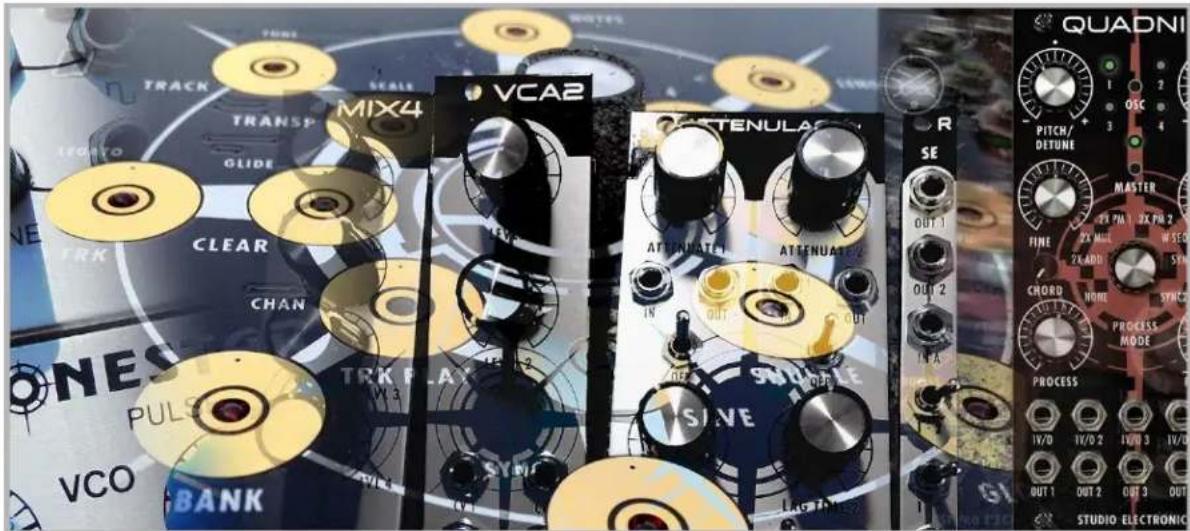
The Backstory
TONE AND TRADITION are the foundation and purpose of Boomstar Modular: big tone, pure tone, historically accurate, classic, warm and fat 5U modular tone under a 3U hood. Three compete synthesizer expressions realize those claims: Modstar Seito Rising - 106hp of modules, 106hp of free space, Modstar Sensei Analog - 240hp, and Modstar Sensei Hybrid - 252hp, wrapped up either in Monorocket cases (while supplies last), or groundbreaking Kahnco shells with 2x 4MS row power. Generate noises or notes; leave the earth sonically, or stay in town and put your good foot down on some bass and lead bounce necessities. Late 2015/2016 collaborations with Marc Sirguy Eowave: Charcot Circles/STE. 16 and Space Hardware: Grainy Clampit/Quadnic make the exploration all the more attractive.
THE BOOMSTAR MODULAR SYSTEM realizes the seemingly inevitable eurorack sprawl of our semi-modular BOOMSTAR desktop synth, consisting of 22 modules that dramatically open up (and expand in ways not imagined) the root level programming and sound sculpting of that lush, potent, and already flexible, semi-modular Boomstar sound.
What makes its core tick: Let's tick a few off them off: Class A 5089, 3003 and AMP*, rugged through-hole construction, discrete circuitry, hand-matched transistors in the filters and amplifier, multi-filtered, hand-crafted, Premium Quality Analog sound. We'd like to think we've learned a few things bringing the MIDIMINI, SE1-X, ATC-X, polyphonic CODE Omega synths, ModMax pedals, C2s, Pre2, and Slate Pro Audio Dragon & Fox to market, and the air waves worldwide.
Our Boomstar Modular System's 5089 circuit is a hybrid design, "utilizing an exponential current source similar the ones from ARP and Oberheim, followed by wave shaping circuits adapted from the 2nd generation MiniMoog oscillator board, and incorporating waveform mixing circuits pioneered by S.E." It is not a style of analog; it's not a type—not reminiscent of, not vintage inspired—it is the analog sound standard manufactured anew, perfected by our time and success-tested refinements, and how we love it so. Apply similar thinking to our 4075, 3003, and SE80 filters vis-à-vis their originals, and you've caught our drift. OSCILLATION and AMP modules also resonate with the Mini's timeless designs, functionality, and gorgeous, gleaming sound—modernized and re imagined by the maestros Tim Caswell and Richard Nicol.
We hope you are as thrilled with your purchase of the complete system/individual modules, as we are with our partnership with Eowave, Space Hardware, the exceedingly savvy folks at Pittsburgh Modular, and the final highly collaborative through-hole designs which flowed from the first Nicol/St. Regis Beer Summit at Winter NAMM '13, culminating in total design integration with Studio Electronics Tim Caswell and Greg St. Regis. All Boomstar Modular modules excepting Pittsburgh's brilliant—and SE optimized—MIDI3, LFO2,
and Outs are manufactured to SE's highest standards of legendary build quality right here in the U. S. A. Take away Pittsburgh's invaluable, real world "euroland" insights, experience, and deep resources—this project would have long since have faded to gray. A tip of the SE chapeau to Richard Nicol, Perry, and the full-strength, generally less-weathered outfit at PGH. And to our direct sales and Guru-in-Chief, Geoff Farr, who relentlessly hounded us St. Regis bros—"When are the euro modules going to be ready to ship?" "Can I get a single Modstar filter pic?" You definitely put on your red shoes...
* Our Class A circuits draw more current from the +12 rail than from the -12 volt rail. If the system power supply is under-sized, hum or buzz may be heard. In that case, larger filter capacitors and/or a larger power transformer will be needed. The 4075 draws equally from both rails, and is more immune to hum.


IMPORTANT INSTRUCTIONS - PLEASE READ
Please read the Boomstar Modular Synthesizer Manual completely before use, and retain for future reference.
IMPORTANT Ribbon Cable Power Information:
Boomstar Modular combines a set of individual modules to create a complete instrument. The individual modules can be rearranged, removed, and replaced with any compatible eurorack modules from Studio Electronics and other manufacturers.
Boomstar Modular uses a standard eurorack power rail to connect the modules to the internal bipolar +/-12v power supply. Please pay very close attention to the orientation of the ribbon cable when adding and removing modules. The stripe on the ribbon cable marks -12v. This stripe needs to line up with the -12v pins on the power rail and the -12v pins on the module. Failure to match up the pins correctly can result in damage to one or all the modules in the Boomstar Modular. On the power rail, the -12v pins are clearly labeled. On the individual modules, the positive and negative sides of the pin connectors are labeled next to the power header on either the top or bottom of the PCB.
Do NOT remove individual modules from the Boomstar while synthesizer is plugged in.
NEVER unplug ribbon cables from the Boomstar Modular, or any other modules while the Boomstar Modular is plugged in.
LIMITED WARRANTY TERMS AND CONDITIONS
This Limited Warranty applies only to ANALOGIA INC./STUDIO ELECTRONICS purchased in the United States of America. Outside the USA, warranty policy and service is determined by the laws of the country of purchase and followed by our local authorized distributor. A listing of our authorized distributors is available at:
- http://www.studioelectronics.com/shop/american-dealers/ for American Dealers and
- http://www.studioelectronics.com/shop/international-dealers/ for International Dealers.
ANALOGIA INC./STUDIO ELECTRONICS warrants to the first owner of a covered product purchased directly from ANALOGIA INC./STUDIO ELECTRONICS, or an authorized ANALOGIA INC./STUDIO ELECTRONICS dealer in the U.S., that this product will be free from defects in materials and or workmanship for a period of one year from the date of purchase. Please register this product online at http://studioelectronics.com/support/registration/ to establish the date of purchase (NOT A REQUIREMENT FOR WARRANTY SERVICE BUT A GOOD IDEA).
To exercise your rights under this Warranty as the first owner/purchaser, YOU MUST SHIP THIS PRODUCT IN ITS ORIGINAL PACKAGING (which we can replace and send to you for \$10) at your expense, with proof of purchase documentation and the ANALOGIA INC./STUDIO ELECTRONICS supplied power adapter, to ANALOGIA INC. An RMA (Return Material Authorization) number from ANALOGIA INC./STUDIO ELECTRONICS must be obtained first before returning any product. Email RMA requests to rma@studioelectronics.com, or call us at (310) 640-3546 to secure an RMA #. Products shipped to ANALOGIA INC. without an RMA will be refused and returned. Shipping insurance is optional, but highly recommended.
ANALOGIA INC./STUDIO ELECTRONICS will repair or replace this product at its sole option and at no charge to you for parts and labor—when deemed necessary and within the warranty period—provided that ANALOGIA INC./STUDIO ELECTRONICS reserves the right to determine whether the product is “defective” for purposes of this Limited Warranty. This Warranty does not apply if damage to this product occurs as a result of abuse or misuse, abnormal use or handling, improper packaging, another product’s interaction, exposure to temperature extremes, or if the product has been altered or modified/ customized in any way, or the damage was caused by unauthorized repair or service. The original product must return to ANALOGIA INC. unaltered.
IN NO EVENT SHALL ANALOGIA INC./STUDIO ELECTRONICS BE LIABLE FOR ANY INDIRECT, INCIDENTAL, COLLATERAL, EXEMPLARY, PUNITIVE, CONSEQUENTIAL OR SPECIAL DAMAGES OR LOSSES ARISING OUT OF YOUR PURCHASE OF PRODUCTS AND/OR OUT OF THIS WARRANTY, INCLUDING WITHOUT LIMITATION, LOSS OF USE, PROFITS, GOODWILL OR SAVINGS OR LOSS OF DATA, MUSIC, ELECTRONIC FILES, OR PREFERENCES THAT MAY HAVE BEEN STORED BY A USER OF THE PRODUCT, EVEN IF ANALOGIA INC./STUDIO ELECTRONICS HAS BEEN ADVISED OF THE POSSIBILITY OF SUCH DAMAGES OR CLAIMS. SOME STATES DO NOT ALLOW THE EXCLUSION OR LIMITATION OF INCIDENTAL, PUNITIVE, OR CONSEQUENTIAL DAMAGES, SO THE ABOVE LIMITATION OR EXCLUSION MAY NOT APPLY TO YOU.
This Limited Warranty and the right of replacement is in lieu of any and all other warranties—which you hereby waive—and it gives U.S. purchasers specific legal rights. You may also have other rights which vary from State to State.
ANALOGIA INC., 530 West Palm Ave. El Segundo, CA 90245
Modular Signal Paths
(Copy courtesy of Pittsburgh Modular)
The BOOMSTAR MODULAR'S signal path is divided into two types of signals: audio signals and control voltages.
The audio signal is the sound that is produced. The audio signal path starts at a sound source such as a Waveforms oscillator, LFO running at audio rate, or the Filter in oscillator mode. The audio signal is then patched through other modules used to shape the sound such as mixers, filters, and amplifiers.
Control voltages (CV) manipulate the audio signal in several different ways.
Gates are represented by a high or low control voltage. A gate can be generated using a square or pulse wave from an oscillator or LFO, or by using a gate output from an external sequencer, or MIDI keyboard. A gate can be shaped using an envelope generator to control the attack, decay, sustain, and release of the gate. The modified gate signal can then be sent to any CV input on the synth.
A second use for control voltages is as a modulation source. For example, a control voltage from the SCI-FI S/H OUT (Sample and Hold) module patched into the 1V/O input on an OSCILLATION module controls the frequency of the oscillator based on the randomly generated sequence of notes, additionally, the OSCILLATION module's full range oscillators make perfect control voltage modulation sources; and audio signals make excellent control voltage source for oscillator FM (frequency modulation). Understanding exactly how it works can sometimes hinder creativity—experiment!
MODSTAR SENSEI ANALOG - \$4995
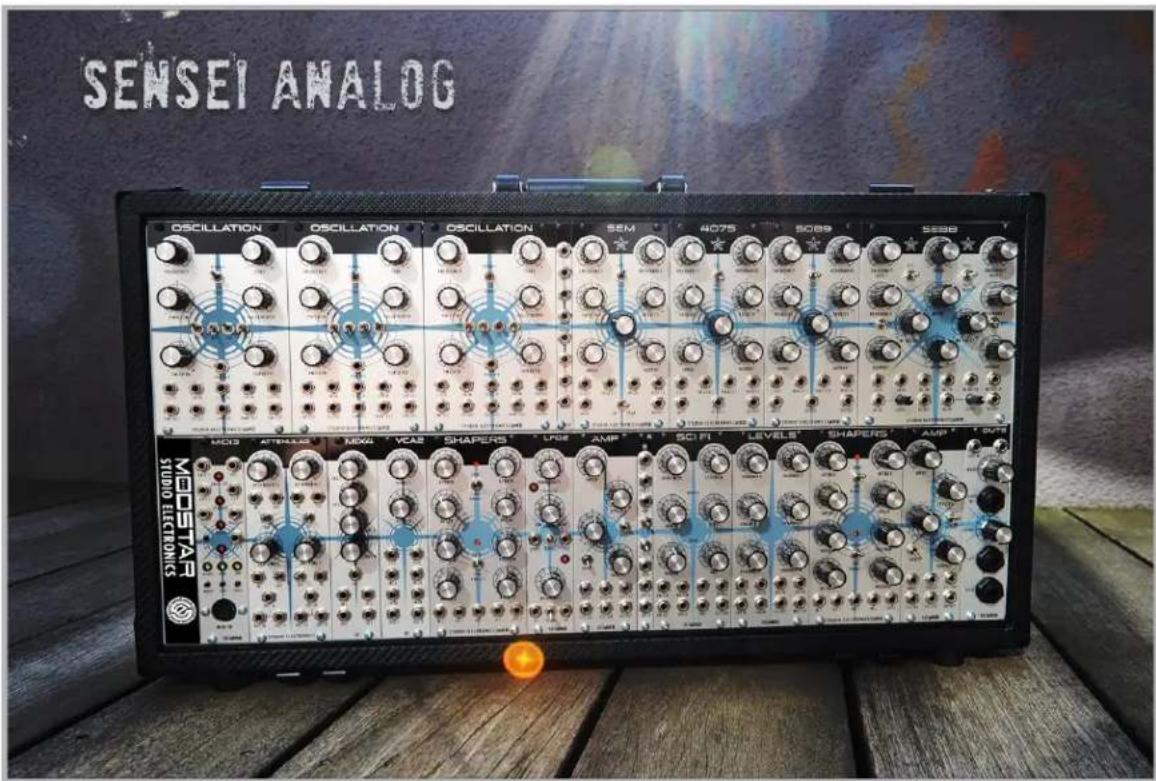
SENSEI ANALOG is a lustrous, three discrete Oscillator, all analog duophonic dream machine (OK, our customized MIDI 3 is a clever forgivable digital necessity) which could, should, be thought of in the same breath as celestial chariots of old—here transporting earthly creations beyond the hammered bowl/barrier of the firmament into a synthetic, sonic paradise. Four supreme, exalted filters: SEM, 4075, 5089 and SE88, one for each Class-A OSC, stamp this Sensei with the trademark SE warmth; the extra SE88 filter provides the final resonant subtraction, and sanction. Our Special Edition SE MonoRocket M6104 Black Carbon Case holds it all together, especially where beefy power delivery, clarity of sound, solid build quality, and handsome, rugged portability are concerned. Internally mounted IEC supply makes your pack & setup nice 'n' easy (one power chord)—does it every time.

MODSTAR SENSEI ANALOG - 212hp Module Breakdown
Top Row: OSCILLATION (x3) 48hp, MULTIPLE 2hp, SEM 12hp, 4075 12hp, 5089 12hp, SE88 20hp. Bottom Row: BRAND PLATE 4hp, MIDI 3 6hp, ATTENULAG 10hp, MIX4 6hp, VCA2 6hp, SHAPERS 12hp, LFO2 6hp, AMP 8hp, ROUTER 2hp, SCI FI 10hp, LEVELS 10hp, SHAPERS 12hp, AMP 8hp, OUT 6hp.
MODSTAR SENSEI - Module Description
4075
Arp-flavored Discrete, voltage controlled, 24/db/oct cascaded transconductance low-pass filter—six pairs of hand-matched transistors—Really a 4-pole ARP 4072 (better: more parts and trims).
5089
Mini-flavored voltage controlled, discrete analog, 24 db/oct transistor ladder, low-pass filter (hand-matched transistors).
- AMP
2 stage Class A discrete design, using 3 pairs of hand matched transistors; DRIVE—'70s era distortion and Drone control.
• LEVELS
Versatile, low-noise six channel summing mixer/attenuator for audio and CV—pots are wired with logarithmic volume curves.
LFO2
Potent all analog dual LFO module; two independent low frequency oscillator circuits provide a variety of modulation options.
MIDI 3
Third generation extremely full-featured MIDI to CV converter, optimized and calibrated by Studio Electronics exclusively for Modstar Systems.
- MULTIPLE
Passive utility module with two independent sections of four linked jacks.
OSCILLATION
Class-A, discrete, DC coupled, output buffered, exponential current source, vintage-designed analog oscillator.
• OUTS
Dual independent output module featuring a stereo 1/4" headphone amplifier output and dual mono 1/4", optimized by Studio Electronics exclusively for Modstar Systems.
• SCI FI
Ring Mod, White and Pink Noise, Sample and Hold—Classic Synth Toolbox, with LFO and slewing control of S&H.
SE88
CS-80 inspired dual resonant powerhouse with hi pass/band reject, low pass/band pass filter modes, and "Pendulum Chaos Generation": a damping/stabilizing override feature for highly unpredictable overloads—input driven "blackout" (perfectly harmless Opamp smashing for smashing good fun).
• SEM
Obi-flavored, 12 Db voltage controlled state variable filter and "Pendulum Chaos Generator": a damping/stabilizing override feature for highly unpredictable overloads—input driven "blackout".
- SHAPERS
Dual four stage envelope generator with independently adjustable attack, decay, sustain, and release stages. Short and long range settings deliver smooth, detailed, and complex expression.
Utility Modules
ATTENULAG
Switchable dual attenuator, 3 output lag generator for CV and audio.
• MIX4
Space conscious, unity gain, 4 in/1 out, high quality audio and CV mixer and "multer".
- ROUTER (R)
Dual bi-directional (despite what the nomenclature states) audio / CV router.
VCA2
Dual high quality VCA for audio or CV level control—perfect for creating a CV modulation chain.
M6104 Specifications
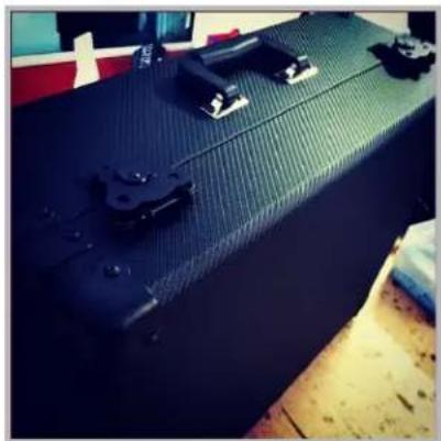
Dimensions : 2 rows / 106hp each (4 hp bonus)
Internal depth 4.5 inches (except area over PSU which is 2 7/8)
External Dimensions with lid attached (H x W x D): 11.5 x 22.5 x 8
Unit stands vertical or lays on its back
Stackable if you detach the handle (4 pan head screws)
Power :
3.5a on the +/-12v rails
500ma of +5v per row installed
15 Doepfer compatible power connections per row (shrouded & keyed)
5 Analogue Solutions power connections per row
Internally mounted 120v and 240v Power Supply Unit - includes IEC power cable
Hardware :
"Sliding Nuts" mounting system - includes mounting screws
MODSTAR SENSEI HYBRID - \5599 Monorocket, \6199 Kahnco

SENSEI HYBRID resists analog purity for richly contrasting tones, modulation, and points of origin and purpose. Two stellar Eowave digital creations: the hypnotic and compelling CHARCOT CIRCLES: a 16 x 8 step sequencer, and STE. 16: a fiery, expansive, dual digital LFO, seem to have been waiting in the wings for just this moment to shine, as you might have guessed from their center-staging. Space Hardware's* GRAINY CLAMPIT: a granular and phase distortion additive oscillator, and QUADNIC: a 4 voice, 64 waveform digital oscillator, pair and push away from our pristine 7+ octave tracking discrete Class-A OSCILLATION module in ways which must be experienced firsthand—a best of both worlds arrangement...
Three revered SE filters more than keep pace: SEM, 4075, and SE88.
Two case options: MonoRocket SE-M6104 Black Carbon Case, and Kahnco Modular Case System, powered by 4MS Row Power 30.
* Think PGH's "Symbiotic Waves".

MODSTAR SENSEI HYBRID, MONOROCKET CASE - 240hp Module Breakdown
Top RowOSCILLATION (x2) 32hp, GRAINY CLAMPIT 18hp, LFO2 6hp, SCI FI 10hp, STE. 16 10hp, SEM12hp, 4075 12hp, SE88 20hp. Bottom Row: MIDI 3 6hp, ATTENULAG 10hp, LEVELS 10hp, VCA2 6hp, SHPR 6hp, AMP 8hp, ROUTER 2hp, CHARCOT CIRCLES 26hp, MULT 2hp, MIX4 6hp, QUADNIC 12hp, SHAPERS 12hp, AMP 8hp, OUTS 6hp.
MODSTAR SENSEI HYBRID, KAHNCO CASE - 252hp Module Breakdown
Top Row: 4MS ROW POWER 30 4hp, OSCILLATION 16hp, QUADNIC 12hp, OSCILLATION 16hp, GRAINY CLAMPIT 18hp, VCA2 6hp, SCI FI 10hp, SEM 12hp, 4075 12hp, SE88 20hp. Bottom Row: 4MS ROW POWER 30 4hp, MIDI 3 6hp, ATTENULAG 10hp, LEVELS 10hp, SHPR 6hp, LFO2 6hp, AMP 8hp, ROUTER 2hp, CHARCOT CIRCLES 26hp, MODSTAR PLATE 4hp, MULT 2hp, MIX4 6hp, SHAPERS 12hp, STE. 16 10hp, AMP 8hp, OUTS 6hp.
MODSTAR SENSEI - Module Description
• 4MS ROW POWER 30
Clean, regulated, and protected power solution for eurorack systems. Row Power 30 provides 30W of power, suited for any typical eurorack row (84HP to 168HP).
4075
Arp-flavored Discrete, voltage controlled, 24/db/oct cascaded transconductance low-pass filter—six pairs of hand-matched transistors—Really a 4-pole ARP 4072 (better: more parts and trims).
5089
Mini-flavored voltage controlled, discrete analog, 24 db/oct transistor ladder, low-pass filter (hand-matched transistors).
- AMP
2 stage Class A discrete design, using 3 pairs of hand matched transistors; DRIVE—'70s era distortion and Drone control.
• CHARCOT CIRCLES
16 x 8 step sequencer, that can be utilized as an 8 x 16 step track preset (8 CVs & gates), 4 x 32 (4 CVs & gates), 2 x 64 (2 CVs & gates), and 1 x 128 step track preset (1 CV, 1 gate). CV and gate expansion via our BBOX (Breakout Box).
• GRAINY CLAMPIT
Granular and phase distortion additive digital oscillator.
• LEVELS
Versatile, low-noise six channel summing mixer/attenuator for audio and CV—pots are wired with logarithmic volume curves.
• LFO2
Potent all analog dual LFO module; two independent low frequency oscillator circuits provide a variety of modulation options.
• MIDI 3
Third generation extremely full-featured MIDI to CV converter, optimized and calibrated by Studio Electronics exclusively for Modstar Systems.
- MULTIPLE
Passive utility module with two independent sections of four linked jacks.
- OSCILLATION
Class-A, discrete, DC coupled, output buffered, exponential current source, vintage-designed analog oscillator.
• OUTS
Dual independent output module featuring a stereo 1/4" headphone amplifier output and dual mono 1/4", optimized by Studio Electronics exclusively for Modstar Systems.
• QUADNIC

Four voice digital oscillator—each with a selection of 64 waveforms, 7 different processing modes including phase distortion and wave sequencing, and a dedicated volt per octave input.
• SCI FI
Ring Mod, White and Pink Noise, Sample and Hold—Classic Synth Toolbox, with LFO and slewing control of S&H.
• SE88
CS-80 inspired dual resonant powerhouse with hi pass/band reject, low pass/band pass filter modes, and "Pendulum Chaos Generation"—damping/stabilizing override feature.
• SEM
Obi-flavored, 12 Db voltage controlled state variable filter and "Pendulum Chaos Generator"—damping/stabilizing override feature.
- SHAPERS
Dual four stage envelope generator with independently adjustable attack, decay, sustain, and release stages. Short and long range settings deliver smooth, detailed, and complex expression.
• SHPR
Half-strength Shapers.
• STE. 16
Dual digital LFO, featuring a hl-freq mode, complex waveform mixing possibilities and expressive patching possibilities.

Utility Modules
- ATTENULAG
Switchable dual attenuator, 3 output lag generator for CV and audio.
• MIX4
Space conscious, unity gain, 4 in/1 out, high quality audio and CV mixer and "multer".
- ROUTER (R)
Dual bi-directional (despite what the nomenclature states) audio / CV router.
• VCA2
Dual high quality VCA for audio or CV level control—perfect for creating a CV modulation chain.
Monorocket M6104 Specifications
Dimensions:
2 rows / 106hp each (4 hp bonus)
Internal depth 4.5 inches (except area over PSU which is 2 7/8)
External Dimensions with lid attached (H x W x D): 11.5 x 22.5 x 8
Unit stands vertical or lays on its back
Stackable if you detach the handle (4 pan head screws)

Power:
3.5a on the +/-12v rails
500ma of +5v per row installed
15 Doepfer compatible power connections per row (shrouded & keyed)
5 Analogue Solutions power connections per row
Internally mounted 120v and 240v Power Supply Unit - includes IEC power cable
Hardware:
"Sliding Nuts" mounting system - includes mounting screws
Kahnco Case Specifications TBA

Modstar Seito Rising 106 hp: MIDI 3 6hp, Router (R—not pictured) 2hp, Oscillation (x2) 32hp, 4075 12hp, M 2hp, Levels 10hp, Sci-Fi 10hp, Shapers 12hp, Amp 8hp, LFO 2 6hp, Outs 6hp. Housed and powered in a sleek and sturdy, carbon-fibre black MONOROCKET M6E case.
Sensei Rising Specifications
• MIDI 3
Third generation extremely full-featured MIDI to CV converter, optimized and calibrated by Studio Electronics exclusively for Modstar Systems.
- MULTIPLE
Passive utility module with two independent sections of four linked jacks—splits signals into three copies.
- OSCILLATION (x2)
Class-A, discrete, DC coupled, output buffered, exponential current source, vintage-designed analog oscillator.
4075
Arp-flavored Discrete, voltage controlled, 24/db/oct cascaded transconductance low-pass filter—six pairs of hand-matched transistors—Really a 4-pole ARP 4072 (better: more parts and trims).
- ROUTER (R)
Bidirectional audio/CV switcher.
• LEVELS
Versatile, low-noise six channel summing mixer/attenuator for audio and CV—pots are wired with logarithmic volume curves.
• SCI FI
Ring Mod, White and Pink Noise, Sample and Hold—Classic Synth Toolbox, with LFO and slewing control of S&H.
- SHAPERS
Dual four stage envelope generator with independently adjustable ATTACK, DECAY, SUSTAIN, and RELEASE stages.
- AMP
2 stage Class A discrete design, using 3 pairs of hand matched transistors; Drive—'70s era "Drive" overdrive/distortion and handy "Drone" control—sends itself its own gate impulse.
LFO2
Potent all analog dual LFO module; two independent low frequency oscillator circuits provide a variety of modulation options.
OUTS
Dual independent output module featuring a stereo 1/4" headphone amplifier output and dual mono 1/4" line level outputs; calibrated and optimized for Boomstar Modular.
M6104 Specifications
M6104 TECHNICAL DETAILS
Dimensions :
2 rows / 106hp each
Internal depth 4.5 inches (except area over PSU which is 2 7/8)
External Dimensions with lid attached (H x W x D): 11.5 x 22.5 x 8
Unit stands vertical or lays on its back
Stackable if you detach the handle (4 pan head screws)
Power :
3.5a on the +/-12v rails
500ma of +5v per row installed
15 Doepfer compatible power connections per row (shrouded and keyed)
5 Analogue Solutions power connections per row
Internally mounted 120v and 240v Power Supply Unit - includes IEC power cable
Hardware :
"Sliding Nuts" mounting system - includes mounting screws
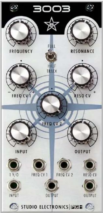
3003 FILTER - \$269
The 3003 filter is a voltage controlled, discrete analog 18 db/oct ladder low-pass filter, employing hand-matched transistors. Drop the FREQUENCY knob to 0 and things get pretty dull; swing it back up and those "Transistor Bass" highs come crashing through the gate. The 3003's RESONANCE circuit at max will sing out more than the TB's signature chirping in a fun, bubbly, if washy, poorer relation, Mini "clone-ish" way; use it tastefully, or throw moderation to the wind for overwhelming chirp force.
Our 3003 filter has the most gentle sonic touch of its partners in the Boomstar fold, but nevertheless is quite capable of shaping precise, very dynamic tone. Whether or not this STUDIO ELECTRONICS filter is filling its traditional baseline boxing niche, driving a harsh, liquid, acid-like tone, a softer more rubber-bandy SH-101-ish voice, or out of the bass range altogether, leading the way, all is within easy reach of this surprisingly warm and versatile VCF. The Modstar 3003 can be distinctly vocal at times, especially when one is willing to put grittier, more distorted desires aside.
Potentiometer Potential
Three attenuverter and four attenuation pots control the FREQUENCY, RESONANCE, FREQ CV 1, RESO CV, FREQ CV 2, INPUT and OUTPUT, delivering smooth, detailed, and complex expression.

Switch it Up
Classic Minimoog FULL and HALF strength filter frequency keyboard/voltage tracking for rounder low end with brilliant highs.
Patch it Up
Seven patch points: 1 V/O, FREQ CV 1, FREQ CV 2, RESO CV, INPUT and 2x OUTPUT direct the deepest manipulation.
All Controls and Patch Points
FREQUENCY – Adjusts the frequency, or cut-off of the filter. RESONANCE – Adjusts the resonance of the filter. * FULL HALF TRACK – Switch between full and half keyboard/voltage tracking. FREQ CV 1 – Frequency control voltage 1 input attenuverter. RESO CV – Resonance control voltage input attenuverter. FREQ CV 2 – Frequency control voltage 2 input attenuverter. INPUT – Adjusts the audio input. OUTPUT – Adjusts the audio output. 1 V/O – One volt per octave control voltage input. FREQ CV 1 – Frequency control voltage 1 input. FREQ CV 2 – Frequency control voltage 2 input. RESO CV – Resonance control voltage input. INPUT – Audio input. OUTPUT x2 – Audio outputs.
Vitals
Size - 12hp
Depth - 39.7mm with ribbon cable attached
Power Usage - 37mA, 25mA (+12 / -12)
* From 7:00 (0) to 9:00 our “Negative Resonance Saturation” adds beefiness, boosting the waveform amplitude and taming waveform transients; set to 9:00 to achieve the cleanest tone possible.
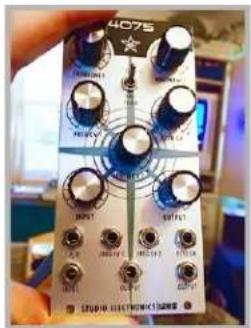
4075 FILTER - \$269
The 4075 filter is a discrete, voltage controlled, 24/db/oct cascaded transconductance low-pass filter, employing six pairs of hand-matched transistors. In its lowest FREQUENCY setting it shaves off higher frequency harmonics; its RESONANCE or "Q" circuit pushes those harmonics past the self-oscillation boiling point, projecting a thumpy, thrashing squeal, with explosive low to mid-range power and depth. The design is actually pulled from the four-pole ARP 4072 (better: more parts and trims), sans the 12kHz design flaw which hamstrung the original's high end. The 4075 name has stuck—no sense correcting our little misnomer misstep now.
Our 4075 filter is the most requested of the Boomstar filter models, perhaps owing to its uniqueness. Has there ever been a better match for a square wave? It weaves dreams with "glidey," 70s basslines, is a natural in the lead department, and feels as if a temper tantrum simmers a mere micron beneath its veneer of faux respectability. Aggressive and articulate, this fresh ARP can snap punishing kick drum sounds out as well as color with bright, edgy, stringy tones for essential arpeggiations.
Potentiometer Potential
Three attenuverter and four attenuation pots control the FREQUENCY, RESONANCE, FREQ CV 1, RESO CV, FREQ CV 2, INPUT and OUTPUT, delivering smooth, detailed and complex expression.
Switch it Up
Classic Minimoog FULL and HALF strength filter frequency keyboard/voltage tracking for rounder low end with brilliant highs.
Patch it Up
Seven patch points: 1 V/O, FREQ CV 1, FREQ CV 2, RESO CV, INPUT and 2x OUTPUT direct the deepest manipulation.
All Controls and Patch Points
FREQUENCY – Adjusts the frequency, or cut-off of the filter. RESONANCE – Adjusts the resonance of the filter. * FULL HALF TRACK – Switch between full and half keyboard/voltage tracking.
FREQ CV 1 – Frequency control voltage 1 input attenuverter. RESO CV – Resonance control voltage input attenuverter. FREQ CV 2 – Frequency control voltage 2 input attenuverter. INPUT – Adjusts the audio input.
OUTPUT – Adjusts the audio output. 1 V/O – One volt per octave control voltage input. FREQ CV 1 – Frequency control voltage 1 input. FREQ CV 2 – Frequency control voltage 2 input. RESO CV – Resonance control voltage input.
INPUT – Audio input. OUTPUT x2 – Audio outputs.


Vitals
Size - 12hp
Depth - 39.7mm with ribbon cable attached
Power Usage - 27mA, 34mA (+12 / -12)
* From 7:00 (0) to 9:00 our "Negative Resonance Saturation" adds beefiness, boosting the waveform amplitude and taming waveform transients; set to 9:00 to achieve the cleanest tone possible.
5089 FILTER - \$269
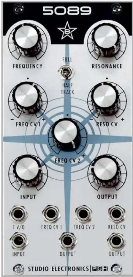
The 5089 filter is a voltage controlled, discrete analog, 24 db/oct transistor ladder, low-pass filter, employing hand-matched transistors. Our ladder low-pass filter—a subtractive analog sound synthesis foundation—in its lowest FREQUENCY setting removes, or cuts off higher frequency harmonics; its RESONANCE or Q circuit emphasizes those harmonics to the point of “squealy,” giddy self-oscillation, tracking the keyboard in its FULL setting quite nicely if seeking an alternative sine wave.
Our 5089 has the roundest, slickest tone of all the Boomstar's filters. Go easy on it, and round, creamy buttery flavors wrap the oscillators in earthy warmth; smash it and a meaty, satisfying overdrive—a maximum harvest of vintage 1960s and 1970s organic sounding, second order harmonic distortion fill the plate. Every setting is balanced and bountiful. Looking for traditional R'n B baselines and leads? Focus here on the rich saturation of this benchmark filter and its symmetrical cascades of generation-stretching timbres. All Boomstar Modular filters are hand-built in the U. S. Pick-and-Place all the way!
Potentiometer Potential
Three attenuverter and four attenuation pots control the FREQUENCY, RESONANCE, FREQ CV 1, RESO CV, FREQ CV 2, INPUT and OUTPUT, delivering smooth, detailed, and complex expression.

Switch it Up
Classic Minimoog FULL and HALF strength filter frequency keyboard/voltage tracking for rounder low end with brilliant highs.
Patch it Up
Seven patch points: 1 V/O, FREQ CV 1, FREQ CV 2, RESO CV, INPUT and 2x OUTPUT direct the deepest manipulation.
All Controls and Patch Points
FREQUENCY – Adjusts the frequency, or cut-off of the filter.
RESONANCE – Adjusts the resonance of the filter. *
FULL HALF TRACK – Switch between full and half keyboard/voltage tracking.
FREQ CV 1 – Frequency control voltage 1 input attenuverter.
RESO CV – Resonance control voltage input attenuverter.
FREQ CV 2 – Frequency control voltage 2 input attenuverter.
INPUT – Adjusts the audio input.
OUTPUT – Adjusts the audio output.
1 V/O - One volt per octave control voltage input.
FREQ CV 1 – Frequency control voltage 1 input.
FREQ CV 2 – Frequency control voltage 2 input.
RESO CV – Resonance control voltage input.
INPUT – Audio input.
OUTPUT x2 – Audio outputs.
Vitals
Size - 12hp
Depth - 39.7mm with ribbon cable attached
Power Usage - 40mA, 27mA (+12 / -12)
* From 7:00 (0) to 9:00 our "Negative Resonance Saturation" adds beefiness, boosting the waveform amplitude and taming waveform transients; set to 9:00 to achieve the cleanest tone possible.
AMP - \$209
From Designer Tim Caswell's own hand:
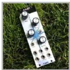
The amplifier (AMP) is a 2 stage Class A discrete design using 3 pairs of hand matched transistors. Envelope is usually applied to ST1/1. ST1/2 goes thru an attenuverter and can be used for envelope or modulation. ST2/1 goes to the 2nd stage, and is typically used for volume control. ST2/2 goes thru an attenuverter and is typically used for modulation.
The AMP, the 5089, and the 3003 are Class A circuits. They draw more current from the +12 rail than from the -12 volt rail. If the system power supply is under-sized, hum or buzz may be heard. In that case, larger filter capacitors and/or a larger power transformer will be needed. The 4075 draws equally from both rails, and is more immune to hum. Like our filters Boomstar Modular AMPs are hand-built entirely in the U. S. of A—just ask Rachael Herbison!
Potentiometer Potential
Two attenuverters and two attenuation pots control the INPUT, ST1 CV2, ST2 CV2, and OUTPUT, delivering smooth, detailed, and complex expression.
Switch it Up
Uber useful continuous hypnotic DRONE for endless sustain/release, and DRIVE—the overdrive circuit from the Boomstar desktop—for last stage energy, bite, soft clipping, and gonzo '70's era "Distortion +" crunchy fuzz.
Patch it Up
Six patch points: INPUT, ST1 CV1, ST1 CV2, ST2 CV1, ST2 CV2, OUTPUT direct the deepest manipulation.
All Controls and Patch Points
INPUT – Adjusts the audio input.
ST1 CV2 – Adjusts stage 1, control voltage 2.
ST2 CV2 – Adjusts stage 2, control voltage 2.
DRONE – Sustains the last note received.
DRIVE – Final output stage overdrive/saturation.
OUTPUT – Adjusts the audio output.
INPUT – Audio input.
ST1 CV1 – Stage 1, control voltage 1 input.
ST1 CV2 – Stage 1, control voltage 2 input.
ST2 CV1 - Stage 2, control voltage 1 input.
ST2 CV2 – Stage 2, control voltage 2 input.
OUTPUT – Audio output.
Vitals
Size - 8hp
Depth - 39.7mm with ribbon cable attached
Power Usage - 35mA, 12mA (+12 / -12)

CHARCOT CIRCLES - \$299
Surrender yourselves to the hypnotic, borderline hysterical sway of the CHARCOT CIRCLES (named for Jean-Martin Charcot* "founder of modern neurology") to awaken your mind and muse. Only the C. C. possesses the organic power and intelligence to identify specific sites in the brain responsible for detailed, sequential, musical functions. Was it not Doc. Jean-Martin who said: "In the last analysis, we see only what we are ready to see, what we have been taught to see."


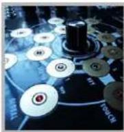

Who can argue with that, or find fault with Marc Sirguy's compelling and mesmerizing design of our 1st eurorack collaboration with Eowave?—a 16 x 8 step sequencer, that can be utilized as an 8 x 16 step track preset (8 CVs & gates), 4 x 32 (4 CVs & gates), 2 x 64 (2 CVs & gates), and 1 x 128 step track preset (1 CV, 1 gate). CV and gate expansion is made possible through our BBOX—breakout box (not yet pictured) interface, which features 4 CVs & 4 gates. Up to 2 breakout boxes per Charcot can be connected.
Think of the hierarchy from top to bottom this way: 8 banks: a collection of up to 16 presets per bank; presets: a collection of tracks composed of 1-16 Notes; and notes: base level data, or steps. Up to 128 presets can be stored in the 8 banks of 16 presets. In TRACK PLAY—the most expressive performance mode—you decide which tracks you want to play together in the preset. In Global mode "8" for instance, tracks 1-8; 1 and 8; 1, 2, 3 and 8—just track 5, etc. In Global mode "4", tracks 1-4; 1, 2, 3; 1 and 4, etc. In Global mode "2", tracks 1, 2; 1; 2. In Global mode "1", 1 track of 128 steps.
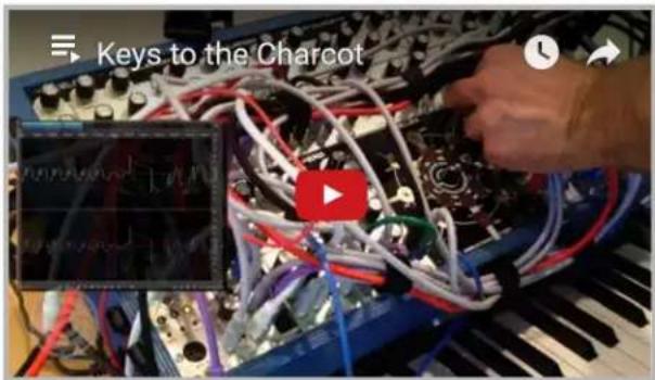
C. C.'s Attraction and Connections
USB in/out, CV in, clock in, reset in, clock out, reset (out), velocity (out), gate (out), CV (out), are certain to attract both scientific and social notoriety. Let your predispositional creativity (think of that as the outer circle of white LEDs) mesh with an inspirational "Circles" influence (think of that as the inner circle of red LEDs) to exceed the threshold of the dissed-ordinary.
Watch what happens when you combine the Charcot Circle's traditionally meticulous design methods with your own novel experimental techniques. Will hypnotism, magnetism, the electricity of sound 'n' soul, the inducement of mania follow, or as some have termed it: "The Beatles Effect"?
THEY WILL!—when you enter the ocularcentric world of Charcot's digital amphitheater.
AT ONCE YOU ARE FEELING MORE RELAXED AND AT THE SAME TIME EXCITED... MORE IN TUNE AND IN TEMPO WITH EVERY STEP YOU SEQUENCE.
* Jean-Martin Charcot was one of France's greatest medical teachers, clinicians and an eponym leader.
Quick Start Guide
Fastest way to get it goin' round in Circles is here.
Sirguy's Feature Breakdown
Press Shift to select mode (large text).
Pad 1. NOTES (steps): Tap on or off to arm notes. 1/8 notes are on the outside circle, 1/16 notes inner. Press and hold a step, turn the encoder to change the pitch. Use to set track length by pressing and holding the last note/step desired; a length of 1 is shortest, 16 is longest. Press any of the 16 touch pads (steps) to set reset point—the last step in a sequence; defaults to the 16th step (for RND TRK and CLEAR see below).
Pad 2. VEL (Velocity): Sets velocity value. Press and hold a step, turn the encoder to change the amount.
Pad 3. LENGTH: Sets length of individual step—think of it as sustain. Press and hold a step, turn the encoder to increase the length to up to 16th bars.

Pad 4. RETRIG (Retrigger): Sets the amount of times the step will be repeated. Press and hold a step, turn the encoder to set the number of repeats.
Pad 5. TOUCH: Pressure sensitive "Key" mode—at this point a stepping Theremin.
Pad 6. KEY: Allows individual control of notes which sustain while pressed (let's you "walk through" your sequence without tempo); also sets note range/reset point for track 1—select one of the 16 pads for the start note, and another for the end. Very liberating feature.
Pad 7. GLOBAL: The first four default parameters set the direction or lack thereof for the sequence:
Forward direction
< Backward direction
Pendulum
RND (Random) Selects a designless firing of notes. To access and change values for Global sub functions TUNE, SCALE, LEGATO, GLIDE, CHAN, SYNC, press and hold desired step, and turn encoder.
TUNE: Tunes the CV output; hold the pad and turn the encoder to adjust the overall tuning.
SCALE: Sets one of sixteen scales; default is chromatic.
LEGATO: Sets the legato; only legato notes will glide.
GLIDE: On/off & speed. Hold the pad and turn the encoder to adjust the glide time.
CHAN (Channel): Sets the base MIDI channel—you only can change the base midi channel; other tracks add that base channel # to their track number like so: if Base MIDI CH is 1, TK 1 -> CH1, TK2-> CH2...
TK8->CH8. If base MIDI CH is 4, TK 1 -> CH4, TK2->CH5... TK8->CH12. If base MIDI CH is 6, TK 1 ->
CH6, TK2-> CH7, TK8-> CH14 and so on.
SYNC: Surrenders sequencer to external clock.
Pad 8. SHUFFLE: Sets swing before or after note.
Pad 9. LOAD: Loads preset into RAM by turning encoder, or selecting preset.
Pad 10. SAVE: Saves presets to 256 locations: 8 banks of 16 presets. Press the encoder to validate your choice.
Pad 11. BANK: Selects 1 of 8.
Pad 12. TRK (TRACK) PLAY: Selects which tracks are played together or not—sets the editing/performance mode for tracks: enable, mute, or edit.
Pad 13. RND TRK (Random Track): Sub-function of NOTES mode. Randomizes entire sequence not just direction. Continued presses produce ever more chaotic results (while in NOTES mode).
Pad 14. CLEAR: Sub-function of NOTES mode. Clears the active preset's tracks (while in NOTES mode).
Pad 15. TRACK (Groups of 1-128 steps): Selects track to be edited on outer circle—mute track on inner circle.
Pad 16. TRANSP (Transpose): Each pressure pad changes key, or turning encoder in TRANSPOSE mode changes key.
SHIFT: Press and hold for selecting feature set mode; pressed together with PLAY upon power recycle will wipe memory.
Highlights, Clarifications, and Recaps
Breakout box (BBox) allows for 4x multichannel/mult-CV use.
Up to 2 breakout boxes can be connected to generate up to 8 CVs and 8 gate outputs.
Per note/track pitch, velocity, and length, with 128 track memory locations.
Patch It
Eight patch points: CV IN, CLOCK IN, RESET IN, CLOCK (out), RESET (out), VEL (out), GATE (out), CV (out).
Patch Points Detail
CV IN – Control voltage input.
CLOCK IN – Clock source can be a square wave or gate signal (positive logic).
RESET IN – Positive voltage resets the Sequencer to the first step.
CLOCK (out) – Outputs a pulse per step. The default step setting is 1/16 (1/16th note). In note mode press SHIFT and PLAY together, then turn the encoder to divide the master tempo.
RESET (out) - Positive reset voltage output.
VEL (out) - Velocity (note/step level) output.
GATE (out) - 0/+5v trigger output.
CV (out) – Control Voltage output.

Additional Connections
USB in/out - MIDI, software update via USB HID Bootloader, importing and exporting sequence data via Max7.
Vitals
Size - 26hp
Depth -
Power Usage - 85 mA +12V, 10 mA -12V
GRAINY CLAMPIT - \$309
GRAINY CLAMPIT is a granular and phase distortion additive oscillator—brand new heavy territory for Studio Electronics... we know; wait till you hear the stunning contrast it creates when paired with our discrete Class-A OSCILLATION module, and the inorganic to downright 1970's combo organy / CS-80-ish tones it can generate. Pure voltage-controlled candy. Be sure to wash off the sticky...
Best to break Granny Clampett's namesake down in stages, and time travel a bit.
First Stage - Additive mixing of 4 harmonics using one of 16 waveforms and one of 16 combinations of harmonics.
Second Stage - Granular or phase distorted mixing of the signal from the first stage, with a sync option.
Back to the First Stage - Additive section with selection of 16 different combinations of harmonics. The harmonics can be based on a sinewave or on one of 15 other waveforms. There's a separate control for mixing the selected harmonics.
Back to the Second Stage - The second processing stage allows granular processing or phase distortion. Granular processing gives you control over grain length and grain position, and can produce sync, detune, and wave sequencing effects. Phase distortion allows the signal from stage one to looked up non-linearly, and can produce thick detune sounds and wildly varying pitch/timbre effects.
Both settings have a choice of long buffer length (for wave sequencing effects) or short buffer length (for smoother detuned effects).
See it's just additive mixing of several combinations of harmonics using a choice of 16 waveforms, followed by granular or phase distortion processing for detuned and wave sequencing effects, with a sync option for further pitch variations. Capiche? A Ver. 1 signal flow chart should help.


Potentiometer Potential
Eight attenuation and three attenuverter pots: WAVE TYPE, OT TYPE, DETUNE, OT MIX CV, PITCH, OT MIX, OT T CV, S/A CV, LEN/PITCH, SPACE/AMT, FINE TUNE.
Switch it Up
GRAIN/PD - Up position: Selects Granular processing - the signal from the Wavetype/OT/Detune section is placed in a buffer, then is read back as 'grains' of sound of variable length. Down position: Selects Phase Distortion processing - the

signal from the Wavetype/OT/Detune section is placed in a buffer, then is read back by a non-linear counter, distorting the waveform of the original signal.
FIX - In Grain mode - Up position allows the Len/Pitch to directly affect the output pitch. Down position syncs this output pitch to the master pitch of the module. In PD mode - Up position allows Len/Pitch to continuously vary the pitch of the phase distorted output. Down position - Len/Pitch sets the pitch of the phase distorted output to musical intervals in respect to the master pitch.

RANGE - The size of the buffer used for Grain/PD processing. Up: Long buffer - results in wave sequencing effects, as the buffer can be heard repeating. Down: Short buffer - gives smoother sounds than the long buffer, which is good for detuned effects.
LOW RES - Gives priority to the 4th bit in the 8 bit digital-to-analog converter. For harsh and noisy sounds.
Patch it Up
1V/OCT - 1 Volt per octave input controlling the overall pitch of the module. Input range is 0 to 10v.
OT T CV -CV control of Overtone Type - allows sequencing through all 16 preset combinations of 4 different harmonics. Input range is +/-10V.
OMX CV - CV control of Overtone Mix - sweeps through the mix of the harmonics, from lower harmonics loudest to higher harmonics loudest. Input range is +/-5V.
S/A CV -CV control of Space/Amount. In Grain mode - controls the spacing/detuning of grains.
In PD mode - controls the amount of non-linearity in the phase distorted output. Input range is +/-10V
OUTPUT - Sound output +/-5V range.
All Controls—arranged in order of signal flow—and Patch Points
WAVE TYPE – Selects one of 16 source waveforms.
OT TYPE – Combines 4 copies of the Wave Type – selects one of 16 variations of four overtones.
OT MIX – Controls the mix of the four overtones, from lowest pitched to highest pitched dominance.
DETUNE – Combines the resulting mix with a copy of itself and detunes it up to one octave.
GRAIN/PD – Selects the next processing stage: Up: Granular, or Down: Phase Distortion.
GRAIN
LEN/PITCH – Sets the grain length, for pitch and sync effects..
SPACE/AMT - Sets the spacing between grains, for detune/wave-sequence effects.
FIX – Up: Len/Pitch controls pitch; Down: Len/Pitch controls sync.
RANGE – Up: Grain sample window is long, for wave sequencing (set Space Amt to 0); Down: Grain sample window is short, for detune effects.
PD
LEN/PITCH – Controls the pitch of the processed sound.
SPACE/AMT - Controls the amount of phase distortion.
FIX – Up: the pitch control of Len/Pitch is continuous; Down: Len/Pitch selects a range of fixed pitches.
RANGE – Up: PD sample window is long, for wave sequencing; Down: PD sample window is short, for detune effects.
Patch Points
1V/OCT - One volt per octave control voltage input.
OTT CV – Overtone Type control voltage.
OMX CV – Oscillator Mix control voltage.
S/A CV – Space Amount control voltage.
OUTPUT – Audio Output.
Vitals
Size - 18hp
Depth - 35mm including connectors
Power Usage - 50mA max
LEVELS - \$149
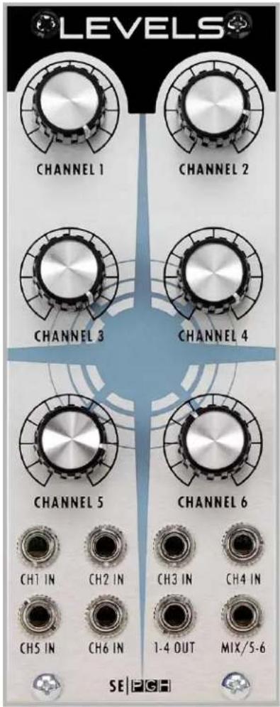
LEVELS is a versatile, low-noise six channel summing mixer/attenuator for audio and CV, which can be used rather effectively in a variety of ways: 6 in 1 out, or two separate mixers: 4 in 1 out, and 2 in 1 out, e.g., when only jacked-in to MIX 5/6 output all input channels pass through; utilizing the 1-4 OUT removes channels 1-4 from the MIX 5/6 output. Handy indeed.
The pots are wired with a logarithmic volume curve that is tuned for use with audio but it will work splendidly with CV as well. Pressing LEVELS into service as a wave-shaper by patching all of the individual OSCILLATION waveform outs (sub, sine, tri, saw, ramp, square) into CHANNEL inputs 1-6, makes for vivid beguiling shapes—a morphable hybrid waveform of your innermost sound designs. Consider pairing the two Modstar modules when building your system.
Potentiometer Potential
Six attenuation pots control CHANNEL 1, CHANNEL 2, CHANNEL 3, CHANNEL 4, CHANNEL 5, and CHANNEL 6.
Patch it Up
Eight patch points: CH1 IN, CH 2 IN, CH 3 IN, CH 4 IN, CH 5 IN, CH 6 IN, 1-4 OUT, MIX/5-6.
All Controls and Patch Points
CHANNEL 1 – Adjusts the level or value of 1.
CHANNEL 2 – Adjusts the level or value of 2.
CHANNEL 3 – Adjusts the level or value of 3.
CHANNEL 4 – Adjusts the level or value of 4.
CHANNEL 5 – Adjusts the level or value of 5.
CHANNEL 6 – Adjusts the level or value of 6.
CH 1 IN – Channel 1 input.
CH 2 IN – Channel 2 input.
CH 3 IN – Channel 3 input.
CH 4 IN – Channel 4 input.
CH 5 IN – Channel 5 input.
CH 6 IN – Channel 6 input.
1-4 OUT – Channels 1-4 output.
MIX/5-6 – All channels output (MIX), or 5-6 when cable is plugged into any of the 1-4 channel inputs.
Vitals
Size - 10hp
Depth - 25mm with ribbon cable attached
Power Usage - 39mA, 40mA (+12 / -12)
Dual Low Frequency Module
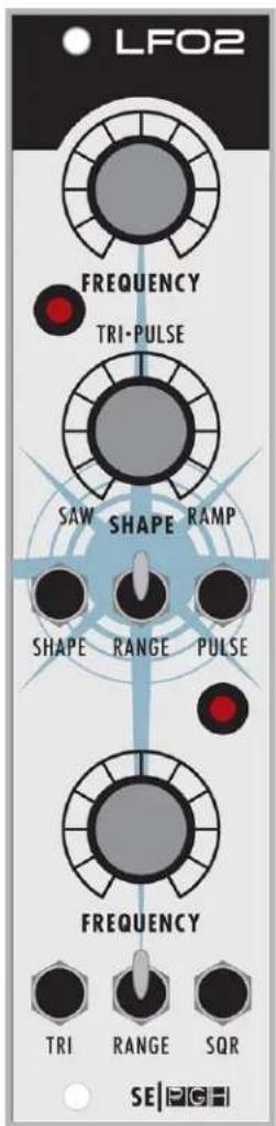
A basic dual LFO module. It uses two different types of low frequency oscillator circuits to provide a variety of modulation options.
LFO 1 - A triangle based low frequency oscillator that utilizes rate and symmetry controls to generate shifting waveforms. Adjusting the symmetry control varies the shape of the TRI output from sawtooth to triangle to ramp, and also adjusts the pulse width of the SQR wave output.
LFO 2 - A simple triangle based low frequency oscillator with rate control over the triangle and square outputs.
Module Controls
LFO 1 (Top)
Rate Knob
Shape Knob: TRI - Saw / Triangle / Ramp Wave Output
Range Switch - Switches the frequency range of LFO 1.
SQR - Square / Pulse Wave Output
LFO 2 (Bottom)
Rate Knob
TRI - Triangle Wave Output
Range Switch - Switches the frequency range of LFO 2.
SQR - Square Wave Output
Vitals
Size - 6hp
Depth- 35mm
Power Usage - 30mA
MIDI 3
The Midi 3 is Pittsburgh Modular's third generation extremely full-featured MIDI to CV converter. It includes a complete set of mono and duophonic midi response modes, assignable CC and dedicated velocity outputs, a feature rich clock source with tap tempo, midi and external gate clock dividers, and multiple arpeggiator responses. This module is deep.
A MIDI to CV module converts standard midi note messages into the analog control voltages used by modular and other analog synthesizers. This allows the synthesizer to be controlled by a midi keyboard, sequencer, or DAW. The two CV outputs on the Midi 3 can be used to control the pitch of an oscillator, cutoff frequency of a filter, or any other function that requires a control voltage signal. The set of Gate outputs on the Midi 3 can be used to trigger envelope generators or other modules expecting a gate or clock source.
The MIDI 3's Three Distinct Performance Modes
Monophonic - Monophonic mode is ideal when using a modular as a single voice synthesizer patch. Channel 2 Gate and CV outputs mirror the outputs of Channel 1. Monophonic mode has several keyboard responses to choose from. Last note priority, low note priority, and high note priority. Each response is available with and without gate retriggering.
Duophonic - The module uses the two sets of Gate and CV outputs to allow two notes to be played simultaneously. The first midi note is sent to Channel 1 Gate and CV outputs and the second is sent to Channel 2 Gate and CV outputs. Duophonic mode has three keyboard response modes to choose from. Unused channel and new note priority, unused channel and low note priority, and split keyboard priority. Duophonic mode is perfect when working with a two voice modular synthesizer patch.
Arpeggiator - The module includes a robust arpeggiator mode with multiple mono and duophonic responses to choose from. Available responses are monophonic response as played, double triggered monophonic response as played, random monophonic response, random monophonic with a random Channel 2 gate, and random duophonic response with dual random gates. The arpeggiator can be clocked using tap tempo, midi clock, or external gate.
The MIDI 3 Module's Three Clock Modes
Internal Clock - The internal Midi 3 clock utilizes the tap tempo button to modify the rate of the internal clock. The internal clock is used to clock the arpeggiator and is also output to the CLOCK jack.
External Midi Clock - The external midi clock responds to midi start/stop messages and midi tempo from an external midi clock source. The external midi clock is used to clock the arpeggiator and is also output to the CLOCK jack. In external midi clock mode, the tap tempo button cycles through five available clock divisions.
External Gate Clock - The external gate clock responds to gate signals patched into the CLOCK jack. The external gate clock is used to clock the arpeggiator. In external gate clock mode, the tap tempo button cycles through six available clock divisions.
![MIDI3 GATE 1 CV 1 [MIDI CH] GATE 2 CV 2 [P BEND] CC VELOCITY [CC #] TAP CLOCK [CLOCK] MONO DUO ARP MODE EDIT HOLD + + MIDI IN SE|PCH](/content/2026/06/1356316/images/668abc52d6ce0c9c04b6474da057b7039130ab8c14f21c4dcbb4f3f23ec81242.jpg)
Additional Features of the MIDI 3
Assignable Midi Channel - Can be assigned to respond to all channels or any individual midi channel.
Assignable Pitch Bend Range - The range of pitch bend can be set to +/- 2 notes, +/- 5th, +/- 1 octave, +/- 2 octaves.
Control Change Output - CC response of 0-5v.
Assignable Control Change Channel Assign - Assign the midi CC channel the Midi 3 responds to. Velocity Output - Velocity response of 0-5v based on active note.
Vitals
Size - 6hp
Depth - 35mm
Power Usage - 50mA
MULTIPLE
Dual Passive Signal Splitter
A passive utility module with two independent sections of four linked jacks. Each section of the Multiple module splits an incoming signal into three copies. This allows one audio or CV signal to be sent to several destinations at once.
Vitals
Size - 2hp
Depth - 20mm
Power Usage - Passive
![graph TD A["●"] --> B["●"] B --> C["●"] C --> D["●"] D --> E["●"] E --> F["●"] F --> G["●"] G --> H["●"] H --> I["●"] I --> J["●"] J --> K["●"] K --> L["●"] L --> M["●"] M --> N["●"] N --> O["●"] O --> P["●"] P --> Q["●"] Q --> R["●"] R --> S["●"] S --> T["●"] T --> U["●"] U --> V["●"] V --> W["●"]…](/content/2026/06/1356316/images/cb90896f0e62c8a2220a119bb2e6dad5a295ac4c58127a4a61c00179529fb957.jpg)
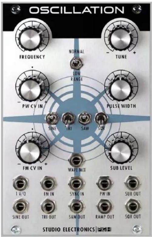
OSCILLATION - \$299
At the beginning of the tone parade, we cheer on another cagey Tim Caswell hybrid, which utilizes an exponential current source in a sympathetic spirit, to the through-hole, glory days circuits of ARP and Oberheim, followed in perfect sync by wave shaping circuits adapted from 2nd generation Minimoog Model D oscillator boards, and an incorporation of waveform mixing circuits pioneered by little old SE; that's us here at STUDIO ELECTRONICS! The gorgeous 100k spray on top all the way down to a boomin' sub bottom, engineer a extravagant variety of tones that would otherwise require several patch cords, and an external mixer; with a two oscillator system, 9 or 10 patch cords and an 8 input mixer would have to be tucked into your carry-on. Where then would you secret your laptop and raw almonds?
What's nice about our OSCILLATION stunner (according to Tim) "is that the waveforms are DC-coupled [components connected directly together without any coupling capacitors], so they keep their shape even at sub-Hz speeds. The outputs are also buffered, so the amplitude is independent of the load they are driving. The waveform levels on some modern eurorack OSCs are often all different, and they vary depending if they go into the mixer or directly to the filter!" Coupling the circuitry without capacitors in-line gives the go-ahead for the full spectrum of frequencies to do their thing, and ensures near identical response over the years—audiophile, transistor-protecting signal path stuff here. You should see these beauts on the scope: a Class-A ballet of balance and proportion, only drawing modest current, evenly from plus and minus.
Potentiometer Potential
Three attenuation, and three attenuverter pots control the FREQUENCY, TUNE, PW CV IN, PULSE WIDTH, FM CV IN, and SUB LEVEL, delivering smooth, detailed, and complex expression.
Switch it Up
NORMAL and LOW RANGE - wide sweeping audio frequencies, or clicks (respectively) for creating a rhythmic pulse or sweep; SINE, TRI, SAW, SQR - your friendly waveform on and offs.
Patch it Up
Eleven patch points: 1 V/O, FM IN, WAVE MIX, SYNC IN, PW IN, SUB OUT, SINE OUT, TRI OUT, SAW OUT, RAMP OUT, SQR OUT direct the deepest manipulation.
All Controls and Patch Points
FREQUENCY – Oscillator frequency attenuator.
NORMAL / LOW RANGE – Oscillator domain switch.
TUNE – Oscillator fine-tune attenuverter.
PULSE WIDTH – Variable pulse wave width control.
SINE – Sine wave on/off.
TRI – Triangle wave on/off.
SAW – Sawtooth wave on/off.
SQR - Square (pulse) wave on/off.
FM CV IN - Frequency Modulation control voltage input attenuverter.
SUB LEVEL – Sub (one octave down) level attenuator.


1 V/O – One volt per octave control voltage input.
FM IN – Frequency Modulation control voltage input.
SYNC IN – Oscillator Sync control voltage input.
PW IN – Pulse Width control voltage input.
SUB OUT – Sub Oscillator output.
SINE OUT – Sine Oscillator output.
TRI OUT – Triangle wave output.
SAW OUT – Sawtooth wave output.
RAMP OUT – Ramp (reverse sawtooth) wave output.
SQR OUT – Square wave output
Vitals
Size - 16hp
Depth - 39.7mm with ribbon cable attached
Power Usage - 20mA, 39mA (+12 / -12)
OUTS
Stereo Output Module / Headphone Amplifier
The simplest way to get sound out of a modular—so our good friends at PGH tell us. Outs is a dual independent output module featuring a stereo 1/4" headphone amplifier output and dual mono 1/4" line level outputs.
Left and Right inputs are available. If only the left input is used, it is sent to both the Left and Right outputs. Handy.
Vitals
Size - 6hp
Depth - 43mm
Power Usage - 30mA

QUADNIC - \$269
QUADNIC reps. our 2nd collaboration with SpaceHardware—a deeply featured 12hp module with four digital oscillators—each with a selection of 64 waveforms, 7 different processing modes including phase distortion and wave sequencing, and a dedicated volt per octave input. In unison mode, all 4 OSCs can be played via the 1st 1V/O CV input and widely detuned, or switched to a preset chord formation—a major move beyond the 'one note samba' monophonic, module choreography we all know and mainly love, but... scooch over Grainy, Quadnic is cookin' up digi-vittles for four. "Come 'n' git it!"
Four Oscillator Structure
| Front Panel | ||||
| Osc Select:Master/Slave: | Osc 1 | Osc 2 | ||
| Osc 1 is always Master | Master | Slave | ||
| Pitch:Fine:1V/Oct 1:1V/Oct 2:1V/Oct 3:1V/Oct 4:Chord:Wave:Bank:Mode:Process:Proc CV:Process CV:Drive:Out 1:Out 2:Out 3:Out 4:Mix Out: | Osc 1 PitchOsc 1 Fine PitchOsc 1 V/OctOsc 1 WaveOsc 1 Wave BankOsc 1 Process ModeOsc 1 Process AmountAll Oscs Process CVAmount of Proc CV to Osc 1Osc 1 Volume/DriveOsc 1 OutOsc 2 OutOsc 3 OutOsc 4 OutOsc 1+2+3+4 Out | Osc 2 PitchOsc 2 Fine PitchOsc 2 V/OctOsc 2 WaveOsc 2 Wave BankOsc 2 Process ModeOsc 2 Process AmountAll Oscs Process CVAmount of Proc CV to Osc 2Osc 2 Volume/DriveOsc 1 OutOsc 2 OutOsc 3 OutOsc 4 OutOsc 1+2+3+4 Out | Osc 1 Pitch +/-20ctsOsc 1 Pitch +/-20ctsOsc 1 Pitch +/-20ctsOsc 1 Pitch +/-20ctsOsc 1 Pitch +/-20ctsOsc 1 Pitch +/-20ctsOsc 1 Pitch +/-20ctsOsc 1 Pitch +/-20ctsOsc 1 Pitch +/-20ctsOsc 1 Pitch +/-20ctsOsc 1 Pitch +/-20ctsOsc 1 Pitch +/-20cts | |
| Osc Select:Master/Slave: | Osc 3Master | Slave | Osc 4Master | Slave |
| Pitch:Fine:1V/Oct 1:1V/Oct 2:1V/Oct 3:1V/Oct 4:Chord:Wave:Bank:Mode:Process:Proc CV:Process CV:Drive:Out 1:Out 2:Out 3:Out 4:Mix Out: | Osc 3 PitchOsc 3 Fine PitchOsc 3 V/OctOsc 3 WaveOsc 3 Wave BankOsc 3 Process ModeOsc 3 Process AmountAll Oscs Process CVAmount of Proc CV to Osc 3Osc 3 Volume/DriveOsc 1 OutOsc 2 OutOsc 3 OutOsc 4 OutOsc 1+2+3+4 Out | Osc 4 PitchOsc 4 Fine PitchOsc 4 V/OctOsc 4 WaveOsc 4 Wave BankOsc 4 Process ModeOsc 4 Process AmountAll Oscs Process CVAmount of Proc CV to Osc 4Osc 4 Volume/DriveOsc 1 OutOsc 2 OutOsc 3 OutOsc 4 OutOsc 1+2+3+4 Out | ||
| Osc Select:Master/Slave: | AllMaster | Slave | ||
| Pitch:Fine:1V/Oct 1:1V/Oct 2:1V/Oct 3:1V/Oct 4:Chord:Wave:Bank:Mode:Process:Proc CV:Process CV:Drive:Out 1:Out 2:Out 3:Out 4:Mix Out: | All Oscs PitchAll Oscs Fine PitchAll Oscs V/OctAll Detune 0-4 octAll Oscs WaveAll Oscs Wave BankAll Oscs Process ModeAll Oscs Process AmountAll Oscs Process CVAmount of Proc CV to All OscsAll Oscs Volume/DriveOsc 1 OutOsc 2 OutOsc 3 OutOsc 4 OutOsc 1+2+3+4 Out | Osc 1 Pitch +/-20cts | ||


Quadnic Quick Guide
The Four Oscillator Structure image gets one into the weeds of the sound. Click here for a purely horizontally oriented vector/text-based pdf.
Parameter Descriptions burrow into the soil. PDF view.
Master Matters
- With MASTER mode switched on, the oscillator responds to it's own CV input.
- Oscillators 2 to 4: If Master LED is not lit, the oscillator responds to CV 1, with the pitch control adding +/-1 octave offset.
- Oscillator 1 always responds to CV input; the other oscillators follow CV 1 if they are not set to Master.
- When all 4 oscillator switches/lights are selected, the Quadnic is in unison mode and all oscillators follow CV 1; the front panel control affects all 4 oscillators.
- To get all oscillators to same pitch, adjust the Pitch and Fine controls.
- To get all oscillators to play the same sound (they are quite independent), adjust all controls.
- All 4 OSC lights on, with Master selected: unison and Chord can detune massively up to 4 octaves.
- All 4 OSC lights on, with master not selected: unison and Chord produce chords.
Parameter Descriptions
| Osc Select | Osc 1 --> Osc 2 --> Osc 3 --> Osc 4 --> All OscSelects the oscillator to be edited from the front panel. |
| Master/Slave: | Master <--> SlaveSelects Master or Slave mode for Osc 2, 3 or 4.Osc 1 is always in Master mode. |
| Pitch: | With Master selected:The pitch of Osc 1, 2, 3 or 4 is controlled by Pitch.With Slave selected:The pitch of Oscillator 2, 3 or 4 is controlled by Osc 1 pitch. In Slave mode, Pitch detunes Osc 2, 3 or 4 by +/- one octave. |
| Fine: | Master : Fine pitch control. |
| Chord: | With All Osc and Master mode selected:Detunes Osc 1 from 0 to +1 octave;Detunes Osc 2 from 0 to -1 octave;Detunes Osc 3 from 0 to +2 octaves;Detunes Osc 4 from 0 to -2 octaves;With All Osc and Slave mode selected:From fully anticlockwise to fully clockwise:No effect;1 octave between oscillators;Octaves and 5ths;Major chord;Minor chord;Dominant 7th;Minor 7th;Major 6th; |
| Wave: | Selects one of the 16 waveforms from the current Bank. |
| Bank: | Selects one of 4 banks of 16 waveforms. |
| Process Mode: | The processing mode for each oscillator.NoneNo effect2x AddAdds a copy of the signal from the oscillator and detunes it using the Process control.2x MulCopies the signal from the oscillator and uses it to modulate the amplitude of the original signal. The Process control also detunes the copied signal.2x PM1Modulates the phase of the oscillator output with a triangle wave. Process controls the frequency of the modulating wave. |
| Process Mode (continue) | 2x PM2Modulates the phase of the oscillator output with a complex waveform. Process controls the frequency of the modulating wave.W SeqWave Sequencing. Steps through all 64 available waveforms. Process controls the rate of wave sequencing.Sync 1Phase distortion changing the shape of the oscillator signal, and producing a mild sync effect.Sync 2Phase distortion producing a dramatic sync effect. |
| Process: | Operation depends on the Process Mode selected.See Process Mode for descriptions. |
| Process CV: | Attenuverter applying the Proc CV input to the selected oscillator.The centre position is no CV applied; fully to the left is inverted CV;fully to the right it non-inverted CV. |
| Drive: | Volume/Drive for the selected oscillator.Fully to the left is no output; centre is full volume; fully to the right is further amplification with hard clipping. |
The 'water table' connections. PDF.
Inputs and Outputs
1V/OCT 1 - Oscillator 1, 1 Volt per octave input. 0-10V input range. Controls the pitch of any other oscillator that is set to Slave mode.
1V/OCT 2 - Oscillator 2, 1 Volt per octave input. 0-10V input range. Only affects oscillator 2 when in Master mode.
1V/OCT 3 - Oscillator 3, 1 Volt per octave input. 0-10V input range. Only affects oscillator 3 when in Master mode.
1V/OCT 4 - Oscillator 4, 1 Volt per octave input. 0-10V input range. Only affects oscillator 4 when in Master mode.
Proc CV - Process CV input. +/-5V input range. One CV input for all oscillators, but can be attenuated for individual oscillators using the Process CV control.
Out 1 - Oscillator 1 output.
Out 2 - Oscillator 2 output.
Out 3 - Oscillator 3 output.
Out 4 - Oscillator 4 output.
Vitals
Size - 12hp
Depth - 35mm including connectors
Power Usage - 50mA max
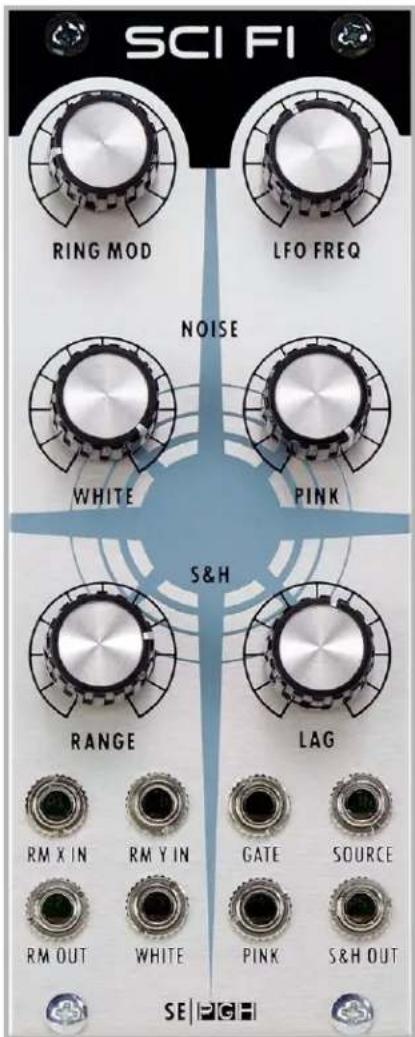
SCI FI - \$259
SCI FI is an ingeniously vintage-circuit-inspired Richard Nicol/Pittsburgh Modular original—jump cut to matttechmodular to see just how much fun can be wrung out of it!
As the reader might already know, ring modulation is a signal-processing electronic function: an implementation of amplitude modulation or frequency mixing, performed by multiplying two signals. This beloved other-worldly, warm, and at times clangorous coloring dates at least as far back to Bode's Melochord of 1947 technology, which was ultimately licensed to Robert Moog in the early 1960s. Of course analog maestros Don Buchla, and Lord Tom Oberheim made their indelible marks, with circuitry culminating—to our ears—in the brilliantly rhythmic, and wildly expressive Yamaha CS-80 Ringmod's sonic alchemy and 'Electone' informed controls.
Back at the Modstar Ranch: The SCI FI's outputted ring-modulated signal is the sum and difference of the frequencies present in each waveform—a signal rich in partials—often producing a haunting, bell-like, metallic, and sometimes softly grinding, understated modulation awash in harmonic and non-harmonic tones. S.E. brought its own brand of dynamic ModMax Pedal-flavored Ringmod to the world in 2002.
SCI FI is getting better all the time with its companion LFO FREQ (low frequency oscillator), true analog PINK, and digital WHITE noise, S & H—a true sample and hold generator, with RANGE control, and LAG generator—a slew limiter which craftily smooths out changes in audio or modulation signals: higher values = smoother signal flowing. This module is every bit as creamy sounding as it is electrically charged: the higher frequencies coat the sound with a sparkling quality one wouldn't naturally expect, but it is a welcome sound indeed.
Potentiometer Potential
Six attenuation pots: RING MOD, LFO FREQ, WHITE, PINK, RANGE, and LAG.
Patch it Up
Seven patch points: RM X IN, RM Y IN, GATE, SOURCE, RM OUT, WHITE, PINK, and S & H OUT.
All Controls and Patch Points
RING MOD – Adjusts the ring mod depth.
LFO FREQ – Adjusts the rate of the sample & hold.
WHITE – Adjusts the white noise level.
PINK – Adjusts the pink noise level.
RANGE – Adjusts the sample & hold depth or intensity.
LAG – Adjusts the sample and hold lag or slew limiting (glide): in the circuit after the sample & hold and before the range attenuator.
RM X IN - Ring Mod X waveform input.
RM Y IN – Ring Mod Y waveform input.
GATE – External gate input for sample & hold.
SOURCE – External audio input for sample & hold.
RM OUT – Ring Mod output.
WHITE – White noise output.
PINK – Pink noise output—the pink noise is normaled to the source input of the sample & hold.
S & H OUT – Sample & hold output.
Vitals
Size - 10hp
Depth - 39.7mm with ribbon cable attached
Power Usage - 48mA, 41mA (+12 / -12)
SE88 FILTER (and Dual Pendulum Chaos Generator) - \$339
Our version of the boxy, Blade Runner-sweet and Boomstar-brash dual mode CS80 filter, initially married to the Omega Series Synths, and then tucked-in the 'Stars, now joins the Modstar Collective. We've twisted and turned the SE88 to unflatten the earth, so to speak; the original CS80 fed a HP filter into a LP filter, but with the SE88 your can select MODE 1's HP or BR to feed MODE 2's LP or BP, or patch it to reverse that pleasant path. The audio signal is completely controllable with input and output levels for each filter.
Cherish and respect your filter's input gain stages, for a smooth yet often brassy sound—shed your mercy to strike hard for boiling, snarling bite, even to the blackout/cutout point (see Greg St. Regis, Tim Caswell, and Marc St. Regis' SEM filter commentary for a detailed diatribe on this "feature too far"); then and only then, uniquely blend mode settings for the filter family values you revere.
To get things merrily modulating, each filter employs attenuverters for frequency and resonance experimentation and decimation. While the SE88 does not self oscillate (Yamaha's creation didn't either), we did amp up the resonance level for full-throttle squelching. An additional master FM (frequency modulation) attenuverter-controlled level can feed both filters (when hungry enough) simultaneously, and tracking switches allow for individual keyboard response for each of the contrasting and complementary filter modes.
Speaking of responses, the Boomstar SE80 - Dual Resonant Powerhouse, features the same core filter architecture, and is our current SoundCloud play king of the hill:

soundcloud.com/studio-electronics/sets/the-se80s.
Potentiometer Potential
Five attenuverter and eight attenuation pots control the FREQUENCY MODE 1, FM IN, FREQUENCY MODE 2, RESONANCE, M1 FM, RESONANCE, M1 RES CV 1, M2 RES CV, INPUT, M2 FM, OUTPUT, LEVEL (M1 OUT), and LEVEL (M2 OUT).
Switch it Up
2/3 - 1/3 TRACK (M1), FULL - HALF TRACK (M2), HP - BR, LP - BP.
Patch it Up
Ten patch points: 1 V/O, FM IN, M1 FM, M2 FM, M1 RES CV, M2 RES CV, M1 IN, M1 OUT, M2 IN, M2 OUT.
All Controls and Patch Points
FREQUENCY MODE 1 – Adjusts the frequency, or cutoff of Mode 1. 2/3 - 1/3 TRACK - Toggles tracking options for Mode 1. FM IN - Adjusts the master frequency modulation input. FULL - HALF TRACK - Toggles tracking options for Mode 2. FREQUENCY MODE 2 - Adjusts the frequency, or cutoff of Mode 2.
RESONANCE – Adjusts the resonance of Mode 1's filter.
M1 FM - Adjusts Mode 1's frequency modulation.
RESONANCE – Adjusts the resonance of the Mode 2's filter.
HP / BR - Toggles the High-Pass and Band-Reject option.
M1 RES CV – Adjusts Mode 1's resonance control voltage.
M2 RES CV – Adjusts Mode 2's resonance control voltage.
INPUT – Adjusts the master audio input.
M2 FM – Adjusts Mode 2's frequency modulation.
OUTPUT – Adjust the audio output.
1 V/O – One volt per octave control voltage input.
FM IN – Master frequency modulation input.
M1 FM – Mode 1 frequency modulation input.
M2 FM – Mode 2 frequency modulation input.
M1 RES CV – Mode 1 resonance control voltage input.
M2 RES CV – Mode 2 resonance control voltage input.
M1 IN – Mode 1 input.
LEVEL – Level control for Mode 1.
M1 OUT – Mode 1 output.
M2 IN – Mode 2 input.
LEVEL – Level control for Mode 2.
M2 OUT – Mode 2 output.
Vitals
Size - 20hp
Depth - 39.7mm with ribbon cable attached
Power Usage - 42mA (+12 / -12)
BYSIB (Before You Send it Back)
This filter (and the SEM) can be "input driven" to the cutout/cutoff/blackout point, for angry, aggressive unpredictability, and staggered, shell-shocked recovery. We wanted it that way; it's perfectly harmless OpAmp smashing, for smashing good fun. Think traumatic movie scene after which an actor's hearing momentarily disappears (extreme wooziness overtakes the balance of his senses—and camera work), high-pitched sounds follow, and then blessed normalcy of awareness and sensory perception gradually, grudgingly return. That. No reboot necessary: just sweep the frequency counterclockwise until it snaps back to its "right mind," and rein in the input and resonance levels—resonance levels below 9:00 are safe; unless of course you want "that" to keep happening. Taunting the edge is entertaining too.
Of Special Note
Two audio paths are involved if you are running the '88 filter in series, so both input levels, and the seeded output level of the 1st stage have to be taken into consideration if a clean sound is desired—either that or keep your resonance setting below 3:00 to avoid the fireworks. This beast's resonance is wide open, with no governor in place—hot-rodded—so expect voltaged chaos when you push it past its "yama-clone" comfort zone.
* From 7:00 (0) to 9:00 our “Negative Resonance Saturation” adds beefiness, boosting the waveform amplitude and taming waveform transients; set to 9:00 to achieve the cleanest tone possible (effect most pronounced on 3003 filter).
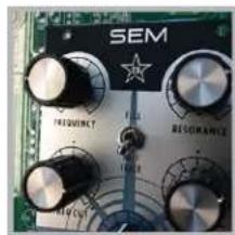
SEM FILTER (and Pendulum Chaos Generator) - \$269
Sensei Caswell: "Our SEM is known as a 'Voltage Controlled State Variable Filter' because it provides simultaneous high pass, low pass, and band pass outputs, all with a 12 dB/oct slope. The notch is the inverse of the bandpass, achieved by summing the low pass and high pass outputs. This version is a combination of the original SEM filter and the newer design from the OBX, along with improvements by SE. It has a modest current draw, which it pulls evenly from the plus and minus rails."
If you've heard the SEM filter in our Boomstar desktop (1) you also know that this 12 dB favorite is "capable of lighter, more subtle tones than the other three models. This isn't to suggest the filter's Low Pass mode can't cater for fat and punchy, because it can." - Paul Nagle, Sound on Sound. Looking for deeply gratifying tonal variance and this emotional warmth? Try (2) our friend Fred Falke's favorite—it can reach into your head and heart, and stay as long as desired. Thank you Lord Tom Oberheim for this marvelous design/template from which we were able to work our very own Studio Electronics eurorack filter enchantments—we do like to hit our SEM a bit harder though ;)
Greg St. Regis on the harder hitting: "The 'bonk out' or sound crash, is a feature, not a fault. We intentionally allow for this to happen by not limiting the input level, but rather boosting it and the resonance level. Some very interesting tones can surface when it pops back and forth between normal and bonk. As most filters do not have an input level, but preset it with a fixed resistor, they are adjusted to eliminate this; it doesn't hurt anything when bonk happens: it is an extreme overload. If you don't want 'blackouts' to occur, lower the input level. As you add more waveforms or oscillators, the level is increased, so you will have to adjust the input level accordingly regardless for a cleaner tone. All the filters are designed to push the input level this way, but only the SEM and SE88 fall apart with too much level. The beauty of this feature, is that you benefit from all the loveliness of a traditional SEM filter

(1) https://soundcloud.com/studio-electronics/sets/mean-sem-ranch/
(2) https://soundcloud.com/alanc3-1/switched-on-sem



by keeping the input and resonance level short of maximum, and have the power to twist the once boxy, gentle circuits into a demented, distorted, peaking and vanishing, snarlingly wild beastly sound. Full variety is what we have provided. GSR"
Tim Caswell on the easy bonking: "Right. This filter is a 'State Variable' circuit, which is an analog computer model of a pendulum. When the resonance is increased, the "damping" or stabilizing of the circuit is actually decreased. This makes the pendulum swing more wildly. If it is hit hard enough, it will swing all the way to one side and 'stick' there, what we call 'bonk out'. Greg likes the sounds that can be gotten as it goes into and out of 'bonk out', so, against my objections, we have not made the filter 'idiot
proof by limiting the input level and resonance amount. If you don't like it, limit your input level and/or resonance amount. Otherwise, go wild! It won't hurt the circuit. TC".
Marc St. Regis on fear and flammability: "Fear not, your SEM is not broken; it does not lie bleeding and battered; distortion is not flammable; you can and will—must—survive this "strange design decision" and all will be right with your 12dB filtered world, biscuits and all. More sound creation possibilities = more better design realities;) MSR"
Potentiometer Potential
Three attenuverter and four attenuation pots control the FREQUENCY, RESONANCE, FREQ CV 1, RESO CV, LP HP, INPUT and OUTPUT, delivering smooth, detailed, and complex expression.
Switch it Up
FULL and HALF strength filter frequency keyboard/voltage tracking, and BP / LP-HP modes.
Patch it Up
Seven patch points: 1 V/O, FREQ CV 1, FREQ CV 2, RESO CV, INPUT, BP LP-HP, and OUTPUT direct the deepest manipulation.
All Controls and Patch Points
FREQUENCY – Adjusts the frequency, or cut-off of the filter.
RESONANCE – Adjusts the resonance of the filter.
FULL HALF TRACK – Switch between full and half keyboard/voltage tracking.
FREQ CV 1 – Frequency control voltage 1 input attenuverter.
RESO CV – Resonance control voltage input attenuverter.
LP HP - Low Pass / High Pass attenuverter.
INPUT – Adjusts the audio input.
OUTPUT – Adjusts the audio output.
1 V/O - One volt per octave control voltage input.
FREQ CV 1 – Frequency control voltage 1 input.
BP OUT – Band Pass Output. No cable patched, BP passes through the mains.
RESO CV – Resonance control voltage input.
INPUT – Audio input.
BP LP-HP – Switch between Band Pass and Low Pass - High Pass modes.
OUTPUT – Audio output.
Vitals
Size - 12hp
Depth - 39.7mm with ribbon cable attached
Power Usage - 32mA (+12 / -12)
BYSIB (Before You Send it Back)
This filter (and the SE88) can be "input driven" to the cutout/cutoff/blackout point, for angry, aggressive unpredictability, and staggered, shell-shocked recovery. We wanted it that way; it's perfectly harmless OpAmp smashing, for smashing good fun. Think traumatic movie scene after which an actor's hearing momentarily disappears (extreme wooziness overtakes the balance of his senses—and camera work), high-pitched sounds follow, and then blessed normalcy of awareness and sensory perception gradually, grudgingly return. That. No reboot necessary: just sweep the frequency counterclockwise until the SEM 'n SE88 snap back to their "right mind," and rein in the input and resonance levels—resonance levels below 9:00 are safe; unless of course you want "that" to keep happening. Taunting the edge is entertaining too.
* From 7:00 (0) to 9:00 our “Negative Resonance Saturation” adds beefiness, boosting the waveform amplitude and taming waveform transients (most pronounced in the 3003 filter): set to 9:00 to achieve the cleanest tone possible.
SHAPERS - \$229
Shapers is a dual four stage envelope generator with independently adjustable ATTACK, DECAY, SUSTAIN, and RELEASE stages. Our Pittsburgh Modular hybrid ADSR smooths the shape of the incoming gates and triggers to produce a more expressive instrument, just like its antecedent. The ADSR output can be used to control the amplitude of an oscillator, the cutoff frequency of a filter or any other function on a module that accepts control voltages.
The functionality of Shapers is easy enough: the incoming gate or trigger signal passes through each of the four stages to output an envelope. When the ADSR module receives a gate or trigger signal, the ATTACK determines the amount of time needed for the envelope generator to reach the peak output voltage and move on to the decay stage. DECAY sets the amount of time needed to transition to the level set by the sustain knob. The SUSTAIN level is maintained as long as the incoming gate remains on or high. Once the incoming gate goes low or off, the release stage takes over. The RELEASE knob sets the time needed to close the envelope and return the ADSR output to 0 volts.
Shapers ENVs. can respond lightening fast or demonstrate the patience of a saint, especially in the LONG RANGE 1 and 2 settings. INV 1 makes topsy-turvy time fun with the inverting of the ADSR 1, and the LED indicators provide a useful visual assist.
Potentiometer Potential
Eight attenuation pots control the ATTACK (x2), DECAY (x2), SUSTAIN (x2), RELEASE (x2), delivering smooth, detailed, and complex expression.
Switch it Up
SHORT and LONG range time settings for both ADSRs.
Patch it Up
Five patch points: IN 1, OUT 1, INV 1, IN 2, and OUT 2 connect and direct the deepest manipulation.

All Controls and Patch Points
ATTACK (x2) - Adjusts the attack stage.
DECAY (x2) - Adjusts the decay stage.
SUSTAIN (x2) - Adjust the sustain stage.
RELEASE (x2) - Adjusts the release stage.
SHORT / LONG RANGE 1 - Selects the envelope range for ADSR 1.
SHORT / LONG RANGE 2 - Selects the envelope range for ADSR 2.
IN 1 - Control voltage input 1.
OUT 1 - Control voltage output 1.
INV 1 - Inverted control voltage output 1.
IN 2 - Control voltage input 2.
OUT 2 - Control voltage output 2.
Vitals
Size - 12hp
Depth - 39.7mm with ribbon cable attached
Power Usage - 16mA, 17mA (+12 / -12)
STE. 16 - \$229
The STE. 16 (our second collab. with eowave designer Marc Sirguy), is a dual LFO, featuring a HI-freq mode and complex waveform mixing possibilities, which thinks nothing of producing thousands of different modulation and audio frequency shifts and wiggles. In fact, it doesn't think at all—well maybe it does... since we here at SE suggested feature tweaks which made the grade;)
The STE's amplitude modulation, frequency modulation, and waveform mixing and blending push the envelope far above and beyond typical/classic four waveform LFOs construction and limit, and so now shall you. The 1 SHOT function dramatically transforms the STE into a punchy and varied percussive tool; applied to an external VCA, one can generate compact and expansive,
concussive encounters. More experimental tonal space can be explored via the AM function, with LFO 1's starting rate somewhere near the low end of the STE.s vibrational spectrum: 5Hz (about 3:40s), and LFO secondi ultimately demanding its 6kHz scream, shatter, and fracture ceiling of thrills and audio frequency chills.
With sixteen waveforms per LFO, setting the initial fragmentizing, gyrating, LoFi digital oscillating process (whenever you are ready), can be a most impulsive, and highly engrossing pursuit.
Common Parameters
SPEED - Sets rate of LFO.
1 SHOT - LFO waveform plays once—needs to be triggered by the reset input.
HI/LO - In HI mode (6kHz at the top of its range) the LFO reaches the audio range—think LoFi digital oscillator; in LO mode, (starting at 5Hz) a very patient 3:40 long sweep is possible.
WAVE - Sets one of 16 different waveforms: triangle, sine, dome, ramp up, ramp down, stairchase, square, 1/2 square, impulse, four decreasing squares, random, random increasing, random pulse with, random triangles, pitched noise, and digital noise.
the type of MIX output.
FM - Frequency modulation from LFO 2 on LFO 1; the Mix pot will set the amount of modulation.
AM - Amplitude modulation from LFO 2 on LFO 1; the Mix pot will set the amount of modulation.
M (MIX) - Mix setting of LFO 1 and LFO 2.
MX (MIX) - Mix output of LFO 1 and LFO 2.
CV - Affects the speed via an external voltage.
RESET - Resets the waveform.
OUT - Balanced LFO output: FM/M/AM three position switch sets the type or mix of modulation outputted.
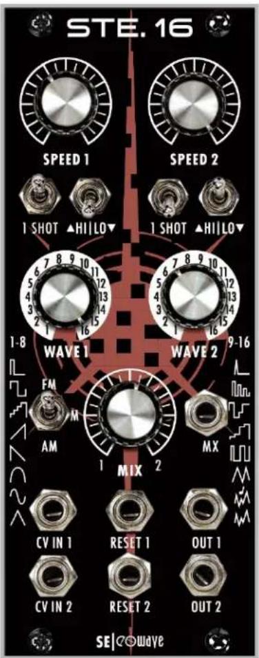


Jacks
Eleven patch points: 1 SHOT, HI/LO (x2), MX, CV In 1, RESET 1, OUT 1, CV In 2, RESET 2, OUT 2.
Vitals
Size - 10hp
Depth - 25mm with ribbon cable attached
Power Usage - 150mA, 35mA (+12 / -12)
UTILITY MODULES - ATTENULAG, MIX4, R (Router), VCA2
Basic but indispensable through-hole synthesizers necessities designed (there's that word again) and assembled in-house. Augment efficiency and expressiveness starting with our handy R (Router) and ascending to its larger and more complex ATTENULAG companion—solidly entertaining to sleep-depriving voltage controlled switching, gliding, combining and amplitude limiting begins here:
ATTENULAG - \$139
Multi-purpose heavy lifter. The attenuators reduce level, audio or CV, when switch is set to off. With the switch up the audio/signal passes through at full level. The inputs are linked together: patching into channel 1 drives both attenuators; patching into channel 2 breaks the link. Experimentation with key tracking to create alternative tunings, or interaction with audio inputs that don't afford attenuation—does good things. The two lag circuits provide a handy CV mult/hub for oscillator and filter tracking (perfect for CV-ing up our OSCILLATION module with its switchable one in/three out structure for both attenuation and slewing—x2) and are linked together: if you patch into channel 1 only, the outputs of both channels are driven (just like the attenuation circuit); patching into channel 2 breaks the link and they become two separate CV mult/lag circuits—envelopes look out.
Four Pots
ATTENUATE 1, ATTENUATE 2, LAG TIME 1, LAG TIME 2.
Four Switches
OFF: the top two handle attenuation duties; the bottom are wired to lag time.
Ten Patch Points
ATTENUATE 1: IN, OUT; LAG TIME 1: IN, OUT 1A, OUT 1B, OUT 1C; ATTENUATE 2: IN, OUT; LAG TIME 2: IN, OUT 2A, OUT 2B, OUT 2C
Common Controls and Patch Points

Attenuation
ATTENUATE – Level reduction.
IN – Attenuation input.
OUT – Attenuation output.
OFF – Bypass is in up position.
Lag
LAG TIME – Exponential slewing amount—still affectionately called glide in some quarters.
IN - Lag input.
OFF – Lag bypass.
OUT A – Lag output A.
OUT B – Lag output B.
OUT C – Lag output C.
Vitals
Size - 10hp
Depth - 25mm with ribbon cable attached
Power Usage - 7mA, 8mA (+12 / -12)
MIX4 - \$99
Space conscious, 4 in/1 out, high quality audio and CV mixer. Originally set at unity gain (along with the VCA2), but tinkering provided useful intell and design changes. Upshot: With the pot set at 3:00 you are at unity, fully clockwise, expect a 2 Volt increase.
Four Pots
LVL 1, LVL 2, LVL3, LVL 4.
Five Patch Points
OUT, IN 1, IN 2, IN 3, IN 4.
All Controls and Patch Points
LVL 1 – Adjusts the level of IN 1.
LVL 2 – Adjusts the level of IN 2.
LVL 3 – Adjusts the level of IN 3.
LVL 4 – Adjusts the level of IN 4.
OUT – Composite output.
IN 1 – Audio/CV input 1.
IN 2 - Audio/CV input 2.
IN 3 – Audio/CV input 3.
IN 4 – Audio/CV input 4.
Vitals
Size - 6hp
Depth - 25mm with ribbon cable attached
Power Usage - 4mA (+12 / -12)

R (ROUTER) - \$59
Two audio or CV routers—bidirectional—despite what the nomenclature states. Bring a signal in and switch between two desirable destinations. Center off switch. Great for instantaneous audio or CV effects: flip your wilson between polar opposites, or subtly nebulous contrasts with your fingers... mainly.
Two Switches
1-2, 1-2
Six Patch Points
OUT 1, OUT 2, IN A (top), IN B, OUT 1, OUT 2 (bottom).
All Controls and Patch Points
OUT 1 - Output #1.
OUT 2 - Output #2.
IN A – Input A.
1-2 (IN A) - Switch between output 1 and 2.
1-2 (IN B) - Switch between output 1 and 2.
IN B - Input B.
OUT 1 - Output #1.
OUT 2 – Output #2.
Vitals
Size - 2hp
Depth -15mm with ribbon cable attached
Power Usage - Passive

VCA2 - \$99
Two quality VCAs for audio or CV with level control—advantageous for creating a CV modulation chain: Patch the 1st (controlling) modulator into the CV input, and the 2nd and 3rd (the controlled) modulators into inputs A and B; the output can then be patched to a modulation destination such as an oscillator or filter frequency. The same approach is effective for enveloping an LFO, or dynamically modulating an LFO or envelope with key velocity, modwheel, key tracking, etc. One can even escape the highly colored Mini-flavord character of our AMP with this quad op-amp alternative for cleaner, sharper tonality in the near final stages of synthesis.
Originally set at unity gain (along with the MIX4), now units with a January 16 (2016) and greater marking will exceed unity and clip the op-amp, past 3:00 on the dial. Upshot: Fully clockwise the gain is doubled. Distortion of audio and modulation signals never hurt anyone, and add another tool to the box.
Note: In the audio realm clipping may occur sooner dependent up signal input level.
Two Pots
LEVEL 1, LEVEL 2.
Eight Patch Points
CV 1, IN 1A, IN 1B, OUT 1; CV 2, IN 2A, IN 2B, OUT 2.
Common Controls and Patch Points
LEVEL – Level/Mix adjustment.
CV - Controlling CV modulation input.
IN A - Controlled Input 1A.
IN B - Controlled Input 1B.
OUT – Output.
Vitals
Size - 6hp
Depth - 25mm with ribbon cable attached
Power Usage - 5mA, 4mA (+12 / -12)
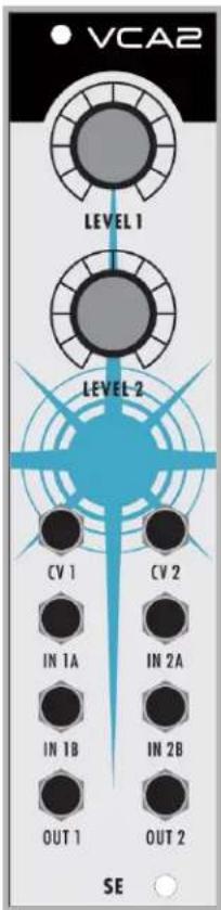
studioelectronics premium quality analog

ANALOGIA INC. - Ardent Proprietors of STUDIO ELECTRONICS
Tel: (310) 640-3546 • Web: www.studioelectronics.com • General Delivery email: support@studioelectronics.com facebook.com/StudioElectronics • twitter.com/SE_BoomStar • youtube.com/user/StudioElectronics • soundcloud.com/studio-electronics
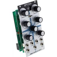


- THE BACKSTORY
- IMPORTANT INSTRUCTIONS - PLEASE READ
- IMPORTANT RIBBON CABLE POWER INFORMATION
- LIMITED WARRANTY TERMS AND CONDITIONS
- MODULAR SIGNAL PATHS
- MODSTAR SENSEI ANALOG - \$4995
- MODSTAR SENSEI ANALOG - 212HP MODULE BREAKDOWN
- MODSTAR SENSEI - MODULE DESCRIPTION
- 4075
- 5089
- AMP
- LEVELS
- LFO2
- MIDI 3
- MULTIPLE
- OSCILLATION
- OUTS
- SCI FI
- SE88
- SEM
- SHAPERS
- UTILITY MODULES
- ATTENULAG
- MIX4
- ROUTER (R)
- VCA2
- M6104 SPECIFICATIONS
- POWER
- HARDWARE
- MODSTAR SENSEI HYBRID - \5599 MONOROCKET, \6199 KAHNCO
- MODSTAR SENSEI HYBRID, MONOROCKET CASE - 240HP MODULE BREAKDOWN
- MODSTAR SENSEI HYBRID, KAHNCO CASE - 252HP MODULE BREAKDOWN
- 4MS ROW POWER 30
- CHARCOT CIRCLES
- GRAINY CLAMPIT
- QUADNIC
- SHPR
- STE. 16
- MONOROCKET M6104 SPECIFICATIONS
- DIMENSIONS
- SENSEI RISING SPECIFICATIONS
- OSCILLATION (X2)
- M6104 TECHNICAL DETAILS
- 3003 FILTER - \$269
- POTENTIOMETER POTENTIAL
- SWITCH IT UP
- PATCH IT UP
- ALL CONTROLS AND PATCH POINTS
- VITALS
- 4075 FILTER - \$269
- 5089 FILTER - \$269
- AMP - \$209
- CHARCOT CIRCLES - \$299
- C.'S ATTRACTION AND CONNECTIONS
- AT ONCE YOU ARE FEELING MORE RELAXED AND AT THE SAME TIME EXCITED... MORE IN TUNE AND IN TEMPO WITH EVERY STEP YOU SEQUENCE
- QUICK START GUIDE
- SIRGUY'S FEATURE BREAKDOWN
- HIGHLIGHTS, CLARIFICATIONS, AND RECAPS
- PATCH IT
- PATCH POINTS DETAIL
- ADDITIONAL CONNECTIONS
- GRAINY CLAMPIT - \$309
- ALL CONTROLS—ARRANGED IN ORDER OF SIGNAL FLOW—AND PATCH POINTS
- GRAIN
- PD
- PATCH POINTS
- LEVELS - \$149
- DUAL LOW FREQUENCY MODULE
- MODULE CONTROLS
- LFO 1 (TOP)
- LFO 2 (BOTTOM)
- THE MIDI 3'S THREE DISTINCT PERFORMANCE MODES
- THE MIDI 3 MODULE'S THREE CLOCK MODES
- ADDITIONAL FEATURES OF THE MIDI 3
- DUAL PASSIVE SIGNAL SPLITTER
- OSCILLATION - \$299
- STEREO OUTPUT MODULE / HEADPHONE AMPLIFIER
- QUADNIC - \$269
- MASTER MATTERS
- THE 'WATER TABLE' CONNECTIONS. PDF
- INPUTS AND OUTPUTS
- SCI FI - \$259
- SE88 FILTER (AND DUAL PENDULUM CHAOS GENERATOR) - \$339
- BYSIB (BEFORE YOU SEND IT BACK)
- OF SPECIAL NOTE
- SEM FILTER (AND PENDULUM CHAOS GENERATOR) - \$269
- SHAPERS - \$229
- STE. 16 - \$229
- COMMON PARAMETERS
- JACKS
- UTILITY MODULES - ATTENULAG, MIX4, R (ROUTER), VCA2
- ATTENULAG - \$139
- FOUR POTS
- ATTENUATE 1, ATTENUATE 2, LAG TIME 1, LAG TIME 2
- FOUR SWITCHES
- TEN PATCH POINTS
- COMMON CONTROLS AND PATCH POINTS
- ATTENUATION
- LAG
- MIX4 - \$99
- FIVE PATCH POINTS
- R (ROUTER) - \$59
- TWO SWITCHES
- SIX PATCH POINTS
- VCA2 - \$99
- TWO POTS
- EIGHT PATCH POINTS
- STUDIOELECTRONICS PREMIUM QUALITY ANALOG
- ANALOGIA INC. - ARDENT PROPRIETORS OF STUDIO ELECTRONICS
Brand : Studio Electronics
Model : Boomstar Modular VCA2
Category : Synthesizer