
DVi34L - Heating Regency - Free user manual and instructions
Find the device manual for free DVi34L Regency in PDF.


| Product Type | Direct Vent Gas Fireplace Insert |
| Brand | Regency |
| Model | DVi34L |
| Dimensions (W x H x D) | 34" x 21.5" x 17" |
| Weight | 165 lbs (75 kg) |
| Fuel Type | Natural Gas or Propane (convertible) |
| Input BTU/h | 28,000 - 33,000 |
| Efficiency (Steady State) | Up to 70% |
| Venting | Direct vent (coaxial 5/8" x 4" or 5" x 8") |
| Controls | Millivolt remote-ready, manual gas valve |
| Ignition | Standing pilot with piezo igniter |
| Log Set | Ceramic fiber logs (6-piece set) |
| Burner | Premium burner with ember bed |
| Blower | Optional variable-speed fan (up to 200 CFM) |
| Safety Features | Pilot safety interlock, overheat protection, tempered glass front |
| Glass | Ceramic glass with high temperature resistance |
| Trim Options | Available in gold, black, or stainless steel |
| Annual Maintenance | Clean glass, inspect logs and burner, check venting annually |
| Warranty | Limited lifetime on firebox, 5 years on components |
Frequently Asked Questions - DVi34L Regency
User questions about DVi34L Regency
0 question about this device. Answer the ones you know or ask your own.
Ask a new question about this device
Download the instructions for your Heating in PDF format for free! Find your manual DVi34L - Regency and take your electronic device back in hand. On this page are published all the documents necessary for the use of your device. DVi34L by Regency.
USER MANUAL DVi34L Regency
Owners & Installation
Manual
LISTINGS AND CODE APPROVALS
These gas appliances have been tested in accordance with AS/NZS 5263.0 & AS/NZS 5263.1.3 and have been certified by the Australian Gas Association for installation and operation as described in these Installation and Operating Instructions. Must be installed as per AS/NZS5601.
Your unit should be serviced annually by an authorised service person.

REGENCY®
FIREPLACE PRODUCTS
DVi34L GAS INBUILT

Models: DVi34LNG
DVi34LLPG
DVi34LULPG
PLEASE KEEP THESE INSTRUCTIONS FOR FUTURE REFERENCE
| WARNING:Improper installation, adjustment, alteration, service or maintenance can cause injury or property damage. Refer to this manual. For assistance or additional information consult an authorised installer, service agency or the gas supplier. | FOR YOUR SAFETYWhat to do if you smell gas:Do not try to light any applianceDo not touch any electrical switch: do not use any phone in your building.Immediately call your gas supplier from a neighbour's phone. Follow the gas supplier's instructions.If you cannot reach your gas supplier, call the fire department. |
| FOR YOUR SAFETYDo not store or use gasoline or other flammable vapours and liquids in the vicinity of this or any other appliance. | |
| Installation and service must be performed by an authorised installer, service agency or the gas supplier. |
REGENCY
GAS INBUILT FIREPLACE
TO THE NEW OWNER
Congratulations! You are the owner of a state-of-the-art Gas Inbuilt Fireplace by FPI. The Regency Gas Fireplace Series of appliances has been designed to provide you with all the warmth and charm of a fireplace, at the flick of a switch. The model DVi34L of this series has been approved by Australian Gas Association for both safety and efficiency. As it also bears our own mark, it promises to provide you with economy, comfort and security for many trouble free years to follow. Please take a moment now to acquaint yourself with these instructions and the many features of your Regency Fireplace.
PAIRING YOUR REMOTE CONTROL
The control box will only learn the remote ID codes during the first 30 seconds after power is applied. After the first 30 seconds, the control box will ignore this special command.
The remote control handset has a set of unique ID codes that are pre-programmed into its memory. This set of ID codes helps differentiate one remote control handset from another; only the control box with a matching ID code will respond to the appropriate remote control handset.
To match the control box, follow these steps:
- Ensure the remote is siwtched off.
- Remove the main power to the control box.
- Reconnect the main power to the control box.
- Press and hold the PROG and FAN buttons simultaneously. The temperature display will show the letters "LC", indicating the ID codes were transmitted, then revert to the normal off mode display.
- Release the PROG and FAN buttons.
The control box will only learn the remote ID codes during the first 30 seconds after power is applied and will ignore this special command from the remote afterward.
Note: The pairing process can be carried out by anyone.
Note: Please visit www.regency-fire.com.au to see the pairing video.
Fan Operation
The fan must be on at all times while the unit is in operation. This model offers a two-speed fan.

WARNING
DO NOT turn your fireplace on via any means or allow to be turned on unless you have conducted a thorough inspection of the area surrounding the fireplace immediately prior to its use, and you have satisfied yourself that there are no materials or other items in proximity to the fireplace which could present a fire risk.
DO NOT turn your fireplace on via any means or allow to be turned on if there are any unsupervised children, infirm or pets in the area surrounding the fireplace.
DO NOT use this fireplace, unless you have read this Manual, and strictly adhere to the user requirements and warnings set out in this Manual.
RELEASE
Without limiting any other acknowledgement, release or indemnity given by you, or limitation of liability, in favour of Fireplace Products Pty Ltd ("Company"), you irrevocably and unconditionally acknowledge and agree that failure to comply with, or strictly adhere to, the requirements and warnings set out in this Manual ("User Requirements") may result in:
- damage to the fireplace;
- damage to property;
- a house fire;
- severe burns or other personal injury; and/or
- death.
Subject to any remedy, guarantee, term, condition, warranty, undertaking, inducement or representation, implied or imposed by any legislation which cannot lawfully be excluded or limited, and to the maximum extent permitted by law:
-
the Company will not be liable for any damage, personal injury or death arising out of or in connection with your failure to comply with any User Requirement; and
-
you release the Company from all claims, actions, proceedings, liabilities, losses and damages in relation to death, any personal injury or property damage arising out of or in connection with your failure to comply with any User Requirement.
UNIT DIMENSIONS - FLUSH INSTALL
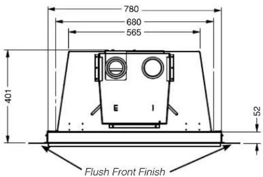


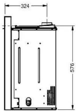
UNIT DIMENSIONS - WITH SPACER


OWNER'S INFORMATION
Paring Your Remote Control ....2
UNIT DIMENSIONS
Unit Dimensions-Flush Install ....4
Unit Dimensions-With Spacer ....5
DATA BADGE
Copy of Data Badge 7
INSTALLATION
Important Message 8
Before You Start 8
Installation Checklist ....8
For Your Safety 8
Materials Required 8
Minimum Fireplace Opening 9
Clearances To Combustibles ....10
Gas Connection ....10
Flueing 10
Flue Liner Installation ....11
Gas Pipe Pressure Testing ....11
Installation in Masonry or Zero Clearance Chimney ....12
System Data 13
Aeration Settings ....13
Conversion from NG to Propane/ULPG....14
Log Set Installation ....15
Glass Door installation ....19
Faceplate & Safety Screen Installation ....20
Optional Spacer Installation ....21
Final Check 22
Wiring 22
OPERATING INSTRUCTIONS
Operating Instructions ....23
Lighting Instructions ......23
Shutdown Instructions ....23
First Fire 23
Remote Control 23
Summary of Controls ....23
Fan Operation 23
Adjusting Flame Height 23
Copy Of Lighting Instruction Plate 24
Normal Operating Sounds Of Gas Appliances .....24
Resetting the unit 24
MAINTENANCE
Maintenance Instructions ....25
Log Replacement 25
Door Glass Replacement 25
Glass Gasket 25
Fan Maintenance ....26
Valve Assembly Replacement ....27
Inner Panel Removal and Installation ....28
Troubleshooting Guide 29
Gas Appliance Mainenance ....31
PARTS LIST
Electronic Components Parts List ....32
Main Assembly 33
Faceplate Assembly 35
WARRANTY
Warranty 36

WARNING!

HOT GLASS WILL CAUSE BURNS
DO NOT TOUCH GLASS UNTIL COOLED
This is a copy of the label that accompanies each Regency DVi34L Gas Inbuilt fireplace. We have printed a copy of the contents here for your review.
DATA BADGE NOTE: Regency units are constantly being improved.
Check the label on the unit and if there is a difference, the label on the unit is the correct one.
Regency Gas Fireplace
Model


Gas Type
NG
PROPANE ULPG
Model
DVi34LNG
| Gas Consumption High | 31.7 MJ/h | 30.6 MJ/h | 26.4 MJ/h | |
| Gas Consumption Low | 21.1 MJ/h | 25.1 MJ/h | 20.9 MJ/h | |
| Min. Supply Pressure | 1.13 kPa | 2.75 kPa | 2.75 kPa | |
| Manifold Pressure High | 0.87 kPa | 2.51 kPa | 2.51 kPa | |
| Manifold Pressure Low | 0.40 kPa | 1.6 kPa | 1.6 kPa | |
| Injector Size | 1 x #37 | 1 x #52 | 1 x #53 | |
| 2.64 mm | 1.61 mm | 1.51 mm |
AS/NZS 5263.0 & AS/NZS 5263.1.3
Approval No. AGA 7469 G SUITABLE ONLY FOR INDOOR INSTALLATION
Electrical: 240VAC 50Hz 1.0 amp
Western Australia:
Air Group Australia
28 Division St
Welshpool, WA 6106
Eastern Australia
Fireplace Products
Australia Pty. Ltd.
99 Colmans Road
Dandenong South, Vic,
Australia 3175
New Zealand
Aber Holdings
17 Main Street Place
Te Rapa, HA 3200
To be installed by an authorised person in accordance with installation instructions provided with the appliance.

N2134
Serial Number
539
920-243b

DO NOT OPERATE THIS APPLIANCE BEFORE READING THE INSTRUCTIONS BOOKLET.
DO NOT PLACE ARTICLES ON OR AGAINST THIS APPLIANCE
DO NOT STORE CHEMICALS OR FLAMMABLE MATERIALS NEAR THIS APPLIANCE.
DO NOT OPERATE WITH PANELS, COVERS OR GUARDS REMOVED FROM THIS APPLIANCE.
THE GUARD IS FITTED TO THIS APPLIANCE TO REDUCE THE RISK OF FIRE OR INJURY FROM BURNS AND NO PART OF IT SHOULD BE PERMANENTLY REMOVED.
FOR PROTECTION OF YOUNG CHILDREN OR THE INFIRM, A SECONDARY GUARD IS REQUIRED.
IMPORTANT MESSAGE
The Regency Gas Inbuilt must be installed in accordance with these instructions. Carefully read all the instructions in this manual first.
Note: Failure to follow these instructions could cause a malfunction of the heater which could result in death, serious bodily injury, and/or property damage. Failure to follow these instructions may also void your fire insurance and/or warranty.
FOR YOUR SAFETY
This appliance requires air for proper combustion. Always provide adequate combustion and ventilation air. Follow instructions and information in the current AS/NZS5601 or local codes. Consult the "authority having jurisdiction" to determine the need for a permit prior to starting the installation.
MATERIALS REQUIRED
A 240 Volt AC power cord is hooked up to the unit. Plug 3 wire cord into a suitable receptacle. Do not cut the ground terminal off under any circumstances.
When connected with 240 volts, the appliance must be electrically grounded in accordance with local codes.
This unit is polarity sensitive and will not operate if polarity is incorrect.
WARNING:
Suitable for installation into a masonry fireplace only.
BEFORE YOU START
Installation is to be carried out ONLY by an authorised person.
1) The appliance shall be installed in accordance with the manufacturer's installation instructions, local gas fitting regulations, municipal building codes, water supply regulations, electrical wiring regulations, with AS/NZS5601.
2) Installation and repair should be done ONLY by an authorised person.
3) The appliance should be inspected before use and at least annually by an authorised service person. More frequent cleaning may be required due to excessive lint from carpeting, bedding material, etc. It is imperative that control compartments, burners and circulating air passageways of the appliance be kept clean and free from excessive lint from carpeting.
4) See general construction and assembly instructions. This appliance may only be installed in a flued, non-combustible fireplace. The appliance and flue should be enclosed when installed or passing through a living area, where children may come in contact with it.
5) Always connect this space heater to a chimney and flue to the outside of the building envelope. Never flue to another room. Make sure that the flue is properly sized and is of adequate height to provide the proper draft.
6) Inspect the flueing system annually for blockage and any signs of deterioration.
7) Any safety glass removed for servicing must be replaced prior to operating the appliance.
8) To prevent injury, do not allow anyone who is unfamiliar with the operation to use the fireplace.
PACKAGING: The unit and its contents are packaged to prevent damage during transport. After unboxing, remove the cardboard spacers and plastic wrap and recycle or dispose of them properly. Carefully remove the logs from inside the unit before commissioning it; unwrap each log and set aside. Refer to subsequent instructions on proper set up and safety check before commissioning the unit.
INSTALLATION CHECKLIST
Before installing vent system ensure that the damper plate is open and secure to prevent the damper plate from falling down and crushing the liner.
The FPI Gas Inbuilt is installed as listed.
1) Check all clearances to combustibles, (Refer to sections "Minimum Fireplace Dimensions and Clearances to Combustibles)
2) Make the gas connection. (Refer to section "Gas Connection")
3) Install the 3" (76.2mm) flue liner to the sliding connector plate. (Refer to section "Flue Liner Installation.")
4) Slide the unit half way into the fireplace.
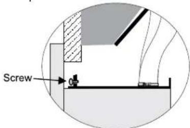
5) Pull the vent connector plate through the tapered brackets and fasten to the front plate. Refer to section "Flue Liner Installation.")
6) Slide the unit fully into the fireplace.
7) Test gas pressure (Refer to section "Gas Pipe Pressure Testing"). Check aeration system (Refer to section "Gas Insert Aeration System").
8) Install standard and optional features. Refer to the following sections:
a. Log Set
b. Faceplate & Door Trim
c. Inner Stainless Panels
9) Final check: Before leaving this unit with the customer, the installer must ensure that the appliance is firing correctly. This includes:
a) Clocking the appliance to ensure the correct firing rate.
b) Adjusting the primary air and restrictor settings, if required, to ensure that the flame does not carbon.
NOTE:
TO BE INSTALLED ON A NON-COMBUSTIBLE FLOOR.
MINIMUM FIREPLACE OPENING
The minimum fireplace openings for the Regency DVi34L gas space heater are shown below:
| Lintel Depth (mm)-A- | Height (mm)-B- | Width Front (mm)-C- | Depth (mm)-D- | Width-Back (mm)-E- | |
| Fascia flush (no spacer) | 275 586 780 406 600 | ||||
| Fascia with spacer 223 | 586 680 353 600 |


CLEARANCES TO COMBUSTIBLES
Minimum Clearances to Combustibles
From Unit
Sides A 255 mm
Ceiling B 1205 mm
| Mantel | C | 330 mm |
| Max. Mantle Depth | E | 305 mm(see Dia. 2) |
Min. Alcove Width F 1220 mm
| Max. Alcove Depth | G | 915 mm |
*No hearth required.
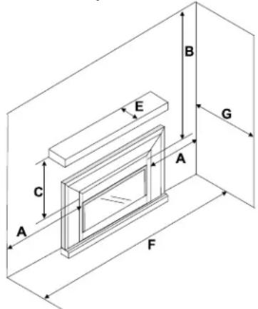
Mantel Clearances

Note: A non-combustible mantel may be installed at a lower height if the framing is made of metal studs covered with a non-combustible board.
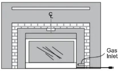
GAS CONNECTION
GAS CONNECTION WARNING: Only persons licensed to work with gas piping may make the necessary gas connections to this appliance.
1) If the appliance is to be installed into an existing chimney system, thoroughly clean the masonry fireplace.
2) The appliance is provided with an opening on the right hand side of the control compartment. The 9.5 mm flexible gas hose provided needs to be brought in from behind this opening. Ensure all gas connections are tight.
3) Locate the center point where the vent will pass through the chimney above the appliance. Move the appliance into the exact location where it is to be installed. Ensure that the Insert is level.
FLUEING
WARNING DO NOT USE AN UNLINED MASONRY CHIMNEY AS THE FLUE FOR THIS APPLIANCE. THE APPLIANCE MUST NOT CONNECT TO A CHIMNEY FLUE SERVING A SEPARATE SOLID FUEL BURNING APPLI- ANCE AND MUST NOT BE TERMINATED TO THE OUTDOORS.
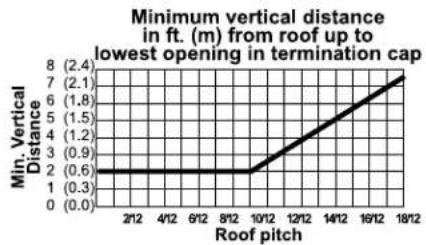
This appliance is designed to be attached to two 76 mm co-linear aluminium flex running the full length of the chimney. The flue length must be a minimum length of 2.44 m and a maximum of 10.7 m. See chart below for minimum distances from roof. Periodically check that the vent is unrestricted.
Masonry chimneys may take various contours which the flexible liner will accommodate. However, keep the flexible liner as straight as possible, avoid unnecessary bending.
The Air Intake pipe must be attached to the inlet air collar of the termination cap.
| Part # | Description |
| 948-640 | 76 mm Flex - 12.2 m |
| 946-549 | Co-linear DV Vertical Termination Cap |

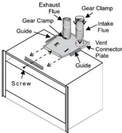
Note: When installing the flueing, identify the flues. Mark one exhaust and one intake as indicated on the top of the unit.

Alternate Termination Cap/Adaptor
| Part # | Description |
| 46DVA-GK | Simpson Duravent Adaptor |
| 46DVA-VCH | Simpson Vertical High Wind Cap |
The Air Intake pipe must be attached to the inlet air collar of the termination cap.
FLUE LINER INSTALLATION
1) Cut the flex liner as required.
2) Mark the end of one liner to indicate Inlet.
3) Connect the other end of the above liner to the inlet side of the termination adaptor, seal connection with high temperature silicone. Secure with gear clamp.
4) Connect the 2nd liner to the exhaust side of the adaptor, seal connection with high temperature silicone. Secure with gear clamp.
5) Install flashing.
6) Insert both liners into chimney, passing through the damper opening.
7) Install termination cap.
8) Connect the marked end of the liner to the inlet collar of the vent connector plate marked with an "I", seal connection with high temperature silicone. Secure with gear clamp.
Install to AS5601 (Australia) / NZS 5262 (New Zealand)

Be careful not to damage thermal insulation when sliding on vent connector plate. This could cause blockage.
9) Connect the 2nd liner to the exhaust collar marked with an "E", seal connection with high temperature silicone. Secure with gear clamp.
GAS PIPE PRESSURE TESTING
The appliance must be isolated from the gas supply piping system by closing its individual manual shut-off valve during any pressure testing of the gas supply piping system at test pressures equal to or less than 3.45 kPa. Disconnect piping from valve at pressures over 3.45 kPa.
The manifold pressure is controlled by a regulator built into the gas control, and should be checked at the pressure test point.
Note: To properly check gas pressure, both inlet and manifold pressures should be checked using the valve pressure ports on the valve.
1) Make sure the valve is in the "OFF" position.
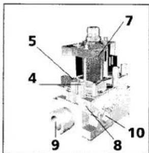
2) Loosen the "IN" (# 3) and/or "OUT" (# 4) pressure tap(s), turning counterclockwise with a small, wide, flat screwdriver.
3) Attach manometer to "IN" and/or "OUT" pressure tap(s) using an 8 mm ID hose.
4) Seal and or check the pilot outlet (# 8)
5) The pressure check should be carried out with the unit burning and the setting should be within the limits specified on the safety label.
6) When finished reading manometer, turn off the gas valve, disconnect the hose and tighten the screw (clockwise) with a small, flat screwdriver. Screw should be snug, but do not over tighten.
S.I.T. Valve Description
1) On-Off Solenoid Valve EV1
2) On-Off Solenoid Valve EV2
3) Inlet Pressure Test Point
4) Outlet Pressure Test Point
5) Connection for Pressure Regulator/Combustion Chamber Compensation
6) Pressure Regulator for Minimum and Maximum Outlet Pressure
7) Gas Outlet Pressure Electric Modulator
8) Pilot Outlet
9) Main Gas Outlet
10) Side Outlet

INSTALLATION IN MASONRY OR ZERO CLEARANCE CHIMNEY
1) Measure and record dimensions to determine total Flex Liner length requirements (see instructions below for details).
2) Carefully feed the liner down the chimney (masonry or zero clearance) and out through the damper. One person should feed liner through the chimney, and another person should pull the liner from the bottom.
3) After carefully feeding the Flex Liner down the chimney to the bottom, form and angle to line up the Flex Liner with the vent opening on the appliance.
Important: Do not let the Flex Liner sag below the level at which it will connect to the appliance or connector. This could allow hot gas to become trapped and potentially become a fire hazard. The Flex Liner path should always be sloped up toward the Termination Cap.
4) Temporarily secure the Flex Liner at the top of the chimney. Be sure to leave 76 mm of flex above the existing chimney to allow for connection to the Termination Kit (Baseplate and Adaptor).

5) Repeat Steps 1-4 for second length of Flex Liner.
6) At the top of the chimney, slide the Baseplate over the tow ends of the Flex Liner and secure it to the surrounding masonry using masonry anchor bolts. Before installing the baseplate, run a bead of non-hardening seal and between the Baseplate and the masonry to prevent moisture from entering the chimney.
Note: Verify that there is sufficient room to mount the Baseplate on to the masonry. You must have a level surface in order to install the Baseplate properly.
7) Attach the Flex Liner ends at the top of the chimney to the Co-Linear to Co-Axial Adaptor. Use four sheet metal screws to connect each Flex Liner run to the Adaptor.
8) Twist lock the Vertical Termination Cap to the Adaptor.
Note: If you are planning to extend the height of the chimney using Direct Vent GS Pipe, please refer to the Direct Vent Installation Instructions for information concerning the proper procedure and restrictions of Direct Vent Pipe.
Also, consult the appliance manufacturer for any height restrictions of the chimney.
9) Connect the Co-Linear Flex to the two outlets on the top of the appliance using four sheet metal screws each. See the appliance manufacturer's instructions for details. Make sure the Flex Liners do not sag behind the appliance. Finally, move the appliance into its appropriate place. Mount the Adaptor to the Baseplate using sheet metal screws.
| System DataDVi34L |
| DVi34LNG: For 0 to 610 meters altitudeDVi34LLPG: For 0 to 610 meters altitudeDVi34LULPG: For 0 to 610 meters altitude |
| Burner Inlet Orifice Sizes:NG Propane ULPGBurner #37 #52 #53 |
| Max. InputNG 31.7 MJ/hPropane 30.6 MJ/hULPG 26.4 MJ/h |
| Min. InputNG 21.1 MJ/hPropane 25.1 MJ/hULPG 20.9 MJ/h |
| Supply PressureNG 1.13 kPaPropane 2.75 kPaULPG 2.75 kPa |
| Manifold Pressure HIGH LOWNG 0.87 kPa 0.4 kPaPropane 2.51 kPa 1.6 kPaULPG 2.51 kPa 1.6 kPa |
| Electrical: 240 V. 50Hz.Circulation: High/Off/LO speed fan,150/89 CFM.Log Set: Ceramic fiber, 7 per set. |
| Aeration SettingNG 13 mm openPropane 13 mm openULPG 13 mm open |
AERATION SETTINGS
The burner aeration is factory set but may need adjusting due to either the local gas supply, air supply or altitude. This adjustment is performed by the installer. (Close the aeration for a more yellow flame, or open it to make the flame bluer).
NG: 13mm open
Propane: 13mm open
ULPG: 13mm open
Note: Any damage due to carboning resulting from improperly setting the aeration and restrictor setting controls is NOT covered under warranty.
CONVERSION KIT #337-968 FROM NG TO PROPANE/ULPG MODEL
Conversion Kit Contains:
Qty. Part # Description
1 904-390 LP Burner Orifice #52
1 904-345 ULPG Buner Orifice #53
1 918-728 Orange "PROPANE" Label
1 918-272 Label "Converted to LPG"
1 910-037 Propane Pilot Injector
1 920-237 Instruction Sheet
1) Shut off the gas supply and unplug the power cord.
2) Remove the glass door, logs and lava rock.
3) Remove the rear log tray by removing the 2 screws. (Log tray must be rotated to clear the burner.)
4) Remove the grate.
5) Remove the burner and ensure the aeration setting is 13 mm open.
6) Remove burner orifice with a 1/2" wrench and discard. Use a wrench to hold on to the elbow behind the orifice.

Burner Orifice
7) Reinstall new burner orifice Propane stamped #52 OR ULPG stamped #53 and tighten
8) Apply the conversion label "This unit has been converted to ULPG" over top of the serial number decal.
Note: Aeration settings do not need to be adjusted.
9) Pull out the pilot hood by hand.


10) Remove the pilot orifice with the allen key.

11) Put in the new pilot orifice with the allen key. Then put back the pilot hood.
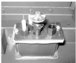
12) Replace the black "NATURAL GAS" label with either orange "PROPANE" label OR red "UNIVERSAL LPG" label.
13) Carefully pull out the control box.
NOTE: The control box is held in place with velcro.
14) Remove the heat shield from the control box by removing the 2 screws.
15) Remove the control box cover by undoing the 3 screws.
Manoeuvre through antenna.

16) Remove the jumper using a plier.


17) Reverse steps 15, 14, 13, 6, 5, 4, 3 & 2.
18) Turn on gas supply and plug in power cord.
19) Adjusting the Outlet Pressure
All the adjustments must be carried out in the following order:
Remove the modulator plastic cap (A) using needle nose pliers.
Maximum pressure: Turn the unit ON to its highest input rating. Screw in the nut (B) to increase the outlet pressure and screw it out to decrease it. Use a 10 mm wrench.
NOTE: The outlet pressure must be set to maximum 2.51 kPa.
Minimum pressure: Remove one of the cables connected to the electric modulator. While holding the nut (B) with a wrench, screw in the screw (C) to increase the pressure and screw it out to decrease it. Use a screwdriver 6 x 1 blade.
NOTE: The outlet pressure must be set to minimum 1.6 kPa.
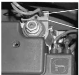
Cable
Electric Modulator
After carrying out all adjustments, block the setting screws with paint, taking care not to obstruct the breather orifice of the pressure.
Put back the modulator plastic cap.
WARNING: To ensure the correct operation of the modulator it is necessary that the plastic cap (A) is returned to its original location.

20) Turn on gas supply and plug in power cord.
21) At the end of all setting and adjustment operations, check electrical installation and gas leaks.
22) Check operation of flame control.
23) Check for proper flame appearance and glow on logs.
Installer Notice: These instructions must be left with the appliance.
LOG SET INSTALLATION
Read the instructions below carefully and refer to the diagrams. If logs are broken do not use the unit until they are replaced. Broken logs can interfere with the pilot operation.
The gas log kit (part # 402-935) contains the following:
a) 02-43 Rear Log
b) 02-45 Front Right Log
c) 02-56 Middle Left Log
d) 02-46 Left Top Log
e) 02-47 Center Log
f) 02-48 Middle Right Log
g) 02-44 Front Left Log
h) 902-154 Embers
i) 902-153 Rockwool
j) 902-179/P Vermiculite
k) 946-669 Platinum Embers
(supplied with packaged manual)

Vermiculite and embers
Vermiculite and embers
Vermiculite and embers
3) Place Rear Log A)02-43 on the two pins on the rear log support.
G) 02-44
C) 02-56
E) 02-47
B) 02-45
The "02" refer numbers (i.e. 02-43) are molded into the rear of each log.

Pins on Rear Log Support
4) Place Front Right Log B)02-45 on the two pins as shown.
Note: Install Optional Brick Panels prior to installing logs.
1) Carefully remove the logs from the box and unwrap them. The logs are fragile, handle with care - do not force into position.
2) Sprinkle the vermiculite around the firebox base. Take some of the embers (approx. 1/3 of the bag) and sprinkle over the vermiculite.
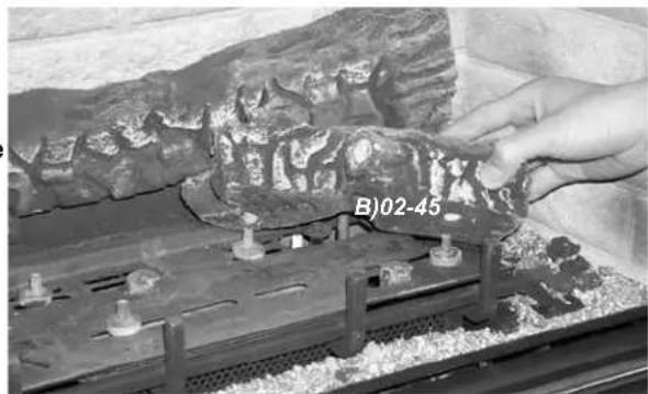
5) Place the Middle Left Log C)02-56 on the two pins as shown.
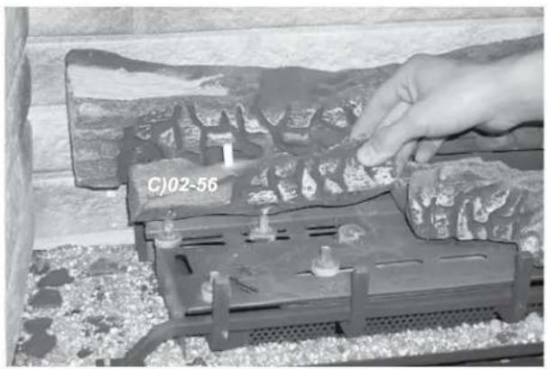
7) Place the notch in Center Log E)02-47 over Log B)02-45 and across the cutout on Log A)02-43.
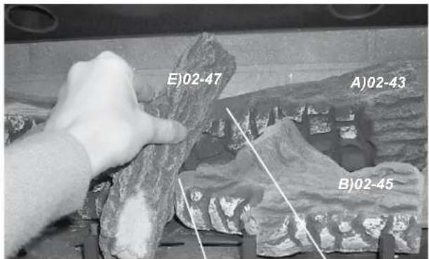
Notch
Cutout

Logs A)02-43, C)02-56, and B)02-45 in position
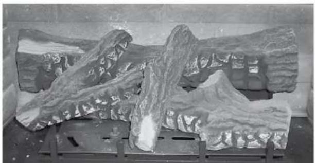
Logs D)02-46 and E)02-47 in position.
6) Place the Left Top Log D)02-46 on the pin on Log C)02-56 and on top of the cutout on Log A)02-43.

Pin
Cutout
8) Position notch in Front Right Log F)02-48 on Log E)02-47 and push the bottom right edge against the bracket on the burner tray and the front edge of the rear burner.
Notch

Front edge of rear burner

The bottom right edge of Log F)02-48 must sit snugly against the bracket and the front edge of the rear burner.
9) Place Front Left Log G)02-44 onto the 2 front pins as shown.

10) Place the embers and Rockwool on the exposed front burner tray.
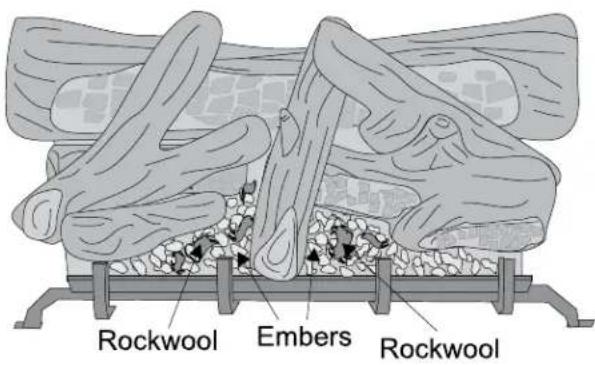
11) Separate platinum embers and place on and around the embers and rockwool on the burner tray. Avoid stacking platinum embers.
12) Test fire to ensure proper light off (make sure flame flows smoothly from one end of burner to the other. If there is any flame hesitation, check that area for any blockage of the burner port.
A) 02-43 D) 02-46
G) 02-48
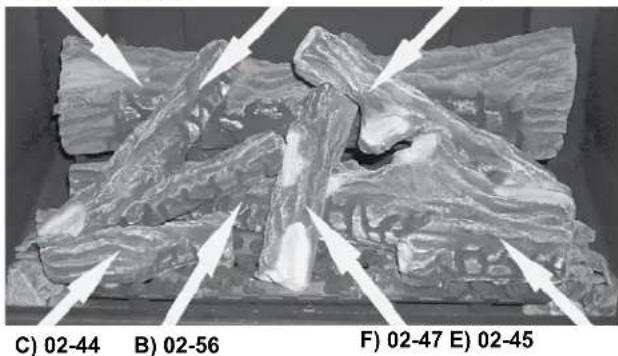
The "02" refer numbers (i.e. 02-43) are molded into the rear of each log.
GLASS DOOR INSTALLATION
STANDARD FLUSH DOOR
The standard flush door comes with a black frame. To install the frame and glass door, simply hook the top door flange onto the top of the unit and swing the door towards the unit, diagram 1. Be careful that the glass gasket does not roll up; there must be a gap between the gasket and the door lip to ensure that the door sits securely on the unit. See Diagram 2.
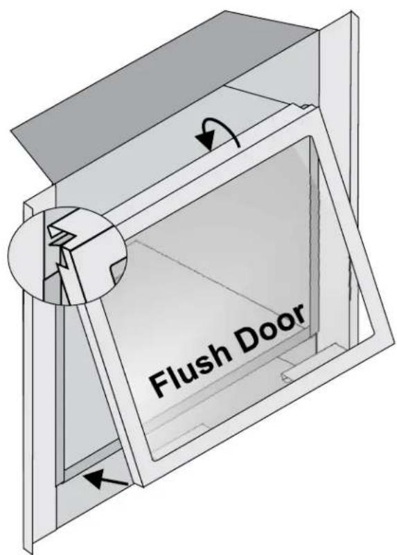

Diagram 1


Diagram 2
Use the hook to pull the spring out until you can put the hook into the slot on the bottom door bracket. Repeat for 2nd spring. See diagram 3.
To remove the flush door, reverse the above steps.

Diagram 3
To remove the flush door, reverse the above steps.
FACEPLATE & SAFETY SCREEN INSTALLATION
| DVi34L Faceplate Assembly (Part #337-914) | ||
| 1 | Faceplate | |
| 2 | Safety Screen | |
| 3 | Lip | |
| 4 | Mesh Bottom Screen | |
| 5 | 948-042 | Hinge and Hnge Support |
| 6 | Bottom Door | |
1) Position faceplate on unit lining up screw holes on faceplate with screw holes on unit - secure with 4 screws.
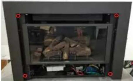
2) Install the bottom Hinges on unit - secure with 4 screws.

3) Install Mesh bottom screen below glass door - secure with 4 screws.

4) Install the Safety screen by hooking the top flange over the top of the glass door.
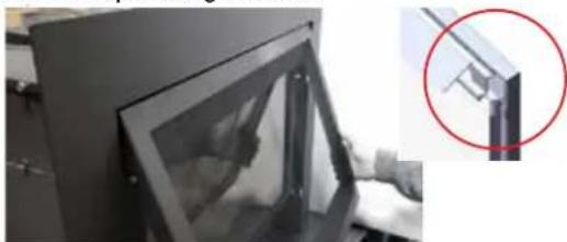

5) Install the bottom door.

6) Flip bottom louver up to close.

7) Insert the lip into the unit.
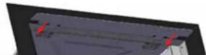

Completed Faceplate & Safety Screen Installation
OPTIONAL SPACER INSTALLATION (PART #337-918)
1) Place the spacer on a soft cloth on the floor. Slide the Right and left spacer into the top spacer (see image #1 below). Secure with 2 screws on each side (see image #2 below).


2) Place the faceplate on a soft cloth on the floor. Attach the spacer to the back of the faceplate with 2 screws on each side.

3) Spacer flange must be placed inside the face-plate flange (see picture below).
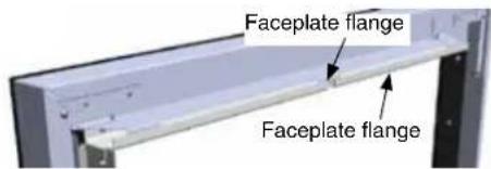

4) Secure the spacer clip at the bottom of the faceplate with 1 screw each side.
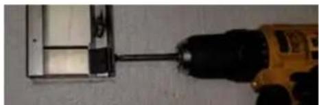

5) For faceplate installation see page
FINAL CHECK
Before leaving this unit with the customer, the installer must ensure that the appliance is firing correctly. This includes:
1) Clocking the appliance to ensure the correct firing rate (rate noted on label) at 15 minutes.
2) If required, adjusting the primary air to ensure that the flame does not carbon. First allow the unit to burn for 15 min. to stabilize.
3) Check for proper draft.
CAUTION
Any alteration to the product that causes sooting or carboning that results in damage to the exterior facia is not the responsibility of the manufacturer.
WIRING
Caution: Ensure that the wires do not touch any hot surfaces and are away from sharp edges.
This unit is polarity sensitive and will not operate if polarity is incorrect.
CAUTION: Label all wires prior to disconnection when servicing controls. Wiring errors can cause improper and dangerous operation.
STANDARD WIRING

OPERATING INSTRUCTIONS
Before operating this appliance, proceed through the following check list.
1) Read and understand these Instructions before operating this appliance.
2) Check to see that all wiring is correct and enclosed to prevent possible shock.
3) Check to ensure there are no gas leaks.
4) Make sure the glass door is in place. Never operate the appliance with the door glass removed.
5) Verify that all flueing and the cap is unobstructed.
6) Verify log placement.
7) The unit should never be turned off and on again without a minimum of a 60 second wait.
8) When lighting the appliance, the inside of the glass may fog up. This will burn off after a few minutes of operation.
LIGHTING INSTRUCTIONS
1) Plug the power cord into a power outlet.
2) Press and release the ON/OFF switch once to start the unit. The LED will be lit.
3) After approximately 8 seconds the spark ignition system will spark for 8 seconds to light the main burner.
4) If the main burner does not light, repeat step 2 to restart the unit.
SHUTDOWN INSTRUCTIONS
1) Press the ON/OFF switch once.
2) The LED will flash.
3) Turn off all electric power to the appliance if service is to be performed.
FIRST FIRE
The FIRST FIRE in your heater is part of the paint curing process. To ensure that the paint is properly cured, it is recommended that you burn your fireplace for at least four (4) hours the first time you use it with the fan on.
When first operated, the unit will release an odour caused by the curing of the paint and the burning off of any oils remaining from manufacturing. Smoke detectors in the house may go off at this time. Open a few windows to ventilate the room for a couple of hours. The glass may require cleaning.
NOTE: The main burner will always start on "HIGH" and resume it's last setting after 20 seconds of operation.
NOTE: When the glass is cold and the appliance is lit, it may cause condensation and fog the glass. This condensation is normal and will disappear in a few minutes as the glass heats up.
DO NOT ATTEMPT TO CLEAN THE GLASS WHILE IT IS STILL HOT!
DO NOT BURN THE APPLIANCE WITHOUT THE GLASS FRONT IN PLACE.
REMOTE CONTROL
Use the Regency Remote Control Kit approved for this unit. Use of other systems may void your warranty.
The remote control kit comes with a hand held transmitter and a wall mounting plate.
1) Choose a convenient location to mount the hand held transmitter, protection from extreme heat is very important.
By using the wall mounting plate to house the transmitter, the remote can also be used as a wall thermostat.

SUMMARY OF CONTROLS
On/Off Button
If the unit is switched off, pressing and releasing this button once will switch the unit on. Flame height and fan speed will be at maximum. The unit will resume its last setting after a few seconds. If the unit is turned on, pressing and releasing the on/off button will switch the unit off.
Flame:
Increase - If the unit is switched on, pressing and releasing the flame plus (+) button once will increase the flame height to the next available high setting.
Decrease - If the unit is switched on, pressing and releasing the flame minus (-) button once will decrease the flame height to the next available low setting.
Fan:
If the unit is switched on, pressing and releasing the FAN button will change the fan speed to the next available setting.
FAN OPERATION
Pressing and releasing the plus (+) FAN button will change the fan speed as follows:
ON->HIGH
Pressing and releasing the minus (-) FAN button will be the reverse of the above. This appliance has 2 speeds, ON & HIGH. The fan cannot be turned off during operation.
Fan must be running at all times when the unit is in operation.
ADJUSTING FLAME HEIGHT
There are six flame settings that can be adjusted by pressing and releasing the plus (+) and minus (-) FLAME button.
MANUAL ON/OFF CONTROL
The manual on/off button can be used to turn the unit on/off. Press the button once to turn the appliance on. Flame height will go to maximum and fan speed will go to HIGH. The appliance will resume its previous setting after a few seconds,
Note: Manual on/off cannot be used to adjust flame hieght or fan speed.
COPY OF LIGHTING INSTRUCTION PLATE
FOR YOUR SAFETY READ BEFORE LIGHTING
This appliance must be installed in accordance with local codes, if any; if not, follow the current CAN1-B149/ANSI Z 223.1, AS/NZS 5601
WARNING: If you do not follow these instructions exactly, a fire or explosion may result causing property damage, personal injury or loss of life. Improper installation, adjustment, alteration, service or maintenance can cause injury or property damage. Refer to the owner's information manual provided with this appliance. For assistance or additional information consult a qualified installer, service agency or gas supplier.
A) BEFORE LIGHTING smell all around the appliance area for gas. Be sure to smell next to the floor because some gas is heavier than air and will settle on the floor.
WHAT TO DO IF YOU SMELL GAS
- Do not try to light any appliance
- Do not touch any electric switch, do not use any phone in your building
- Immediately call your gas supplier from a neighbors phone. Follow the gas supplier's instructions.
- If you cannot reach your gas supplier, call the fire department.
B) Do not use this appliance if any part has been under water. Immediately call a qualified service technician to inspect the appliance and to replace any part of the control system and any gas control which has been under water.
This appliance needs fresh air for safe operation and must be installed so there are provisions for adequate combustion and ventilation air.
CAUTION: Hot while in operation. Do not touch. Severe Burns may result. Due to high surface temperatures keep children, clothing and furniture, gasoline and other liquids having fammable vapors away. Keep burner and control compartment clean. See installation and operating instructions accompanying appliance.
LIGHTING INSTRUCTIONS
STOP! Read the safety information above on this label.
1) Plug the power cord into a power outlet.
2) Press and release the ON/OFF button once to start the unit.
3) After approximately 3 seconds the spark ignition system will spark for 25 seconds to light the main burner.
4) If the main burner does not light, check the gas and reset the unit.
TO TURN OFF GAS APPLIANCE
1) Press the ON/OFF button once.
2) Turn off all electric power to the unit if service is to be performed.
DO NOT REMOVE THIS INSTRUCTION PLATE
918-332a
WARNING:
DO NOT SPRAY AEROSOLS IN THE VICINITY OF THIS APPLIANCE WHILE IN OPERATION.
DO NOT USE OR STORE FLAMMABLE MATERIALS IN OR NEAR THIS APPLIANCE.
DO NOT PLACE ARTICLES ON OR AGAINST THIS APPLIANCE.
DO NOT MODIFY THIS APPLIANCE.
In the event of power loss or outage, the appliance will shut down automatically. To return to normal operation, the appliance will have to be restarted. To restart, press the ON/OFF switch on the unit or on the remote.
"Appliances incorporating a live fuel effect and designed to operate with luminous flames may exhibit slight carbon deposition."

NORMAL OPERATING SOUNDS OF GAS APPLIANCES
It is possible that you will hear some sounds from your gas appliance. This is perfectly normal due to the fact that there are various gauges and types of steel used within your appliance. Listed below are some examples. All are normal operating sounds and should not be considered as defects in your appliance.
Blower:
Regency gas appliances use high tech blowers to push heated air farther into the room. It is not unusual for the fan to make a "whirring" sound when ON. This sound will increase or decrease in volume depending on the speed setting of your fan speed control.
Burner Tray:
The burner tray is positioned directly under the burner tube(s) and logs and is made of a different gauge material from the rest of the firebox and body. Therefore, the varying thicknesses of steel will expand and contract at slightly different rates which can cause "ticking" and "cracking" sounds. You should also be aware that as there are temperature changes within the unit these sounds will likely re-occur. Again, this is normal for steel fireboxes.
Gas Control Valve:
As the gas control valve turns ON and OFF, a dull clicking sound may be audible, this is normal operation of a gas regulator or valve.
Unit Body/Firebox:
Different types and thicknesses of steel will expand and contract at different rates resulting in some "cracking" and "ticking" sounds will be heard throughout the cycling process.
RESETTING THE UNIT
If the appliance goes to 'lockout', the system will have to be reset by depressing the reset button - located behind bottom louver.
*Important: Wait at least 5 min for any unburned gas to clear before resetting the appliance.
1) Open the bottom louver on the unit.
2) With the unit switched on, press and release the reset button once. The button is located near the gas valve. Wait for approximately 3 seconds - the pilot sparks can be heard and seen. It will take approximately 2 to 3 seconds for the flame to light.
NOTE: Wait 30 seconds between reset attempts.
MAINTENANCE INSTRUCTIONS
Any maintenance required accessing the glass door of the unit must be performed by an authorized service person.
1) Always unplug the power cord before cleaning. For relighting, refer to lighting instructions. Keep the burner and control compartment clean by brushing and vacuuming at least once a year. When cleaning the logs, use a soft clean brush as the logs are fragile and easily damaged.
2) Clean glass (never when unit is hot), appliance, louvres, and door with a damp cloth. Never use an abrasive cleaner. The gold louvres (and optional gold door) may be scratched if abrasives are used to clean them.
The heater is finished in a heat resistant paint and should only be refinished with heat resistant paint (not with wall paint). Regency uses StoveBright Paint - Metallic Black #6309.
3) Make a periodic check of burner for proper position and condition. Visually check the flame of the burner periodically, making sure the flames are steady; not lifting or floating. If there is a problem, call an authorized service person.
4) The appliance and flueing system must be inspected before use, and at least annually, by an authorized field service person, to ensure that the flow of combustion and ventilation air is not obstructed.
During the annual service call, the burners should be removed from the burner tray and cleaned. Replace the embers - do not block the burner ports.
5) Keep the area near the appliance clear and free from combustible materials, gasoline and other flammable vapours and liquids.
6) Verify proper operation after servicing.
WARNING: CHILDREN AND ADULTS SHOULD BE ALERTED TO THE HAZARDS OF HIGH SURFACE TEMPERATURE AND SHOULD STAY AWAY TO AVOID BURNS OR CLOTHING IGNITION. YOUNG CHILDREN SHOULD BE CAREFULLY SUPERVISED WHEN THEY ARE IN THE SAME ROOM AS THE APPLIANCE.

WARNING

HOTGLASS WILL CAUSEBURNS
DONOTTOUCH GLASS UNTILCOOLED
CAUTION: ANY SAFETY SCREEN OR GUARD REMOVED FOR SERVICING AN APPLIANCE MUST BE REPLACED PRIOR TO OPERATING THE APPLIANCE.
CLOTHING OR OTHER FLAM- MABLE MATERIAL SHOULD NOT BE PLACED ON OR NEAR THE APPLIANCE.
DO NOT USE THIS APPLIANCE IF ANY PART HAS BEEN UNDER WATER. IMMEDIATELY CALL AN AUTHORIZED SERVICE TECHNICIAN TO INSPECT THE APPLIANCE AND TO REPLACE ANY PART OF CONTROL SYSTEM AND ANY GAS CONTROL WHICH HAS BEEN UNDER WATER.
LOG REPLACEMENT
The unit should never be used with broken logs. Unplug the power cord and allow the unit to cool before opening door to carefully remove the logs. If for any reason a log should need replacement, you must use the proper replacement log. The position of these logs must be as shown in the diagram under Log Installation.
Note: Improper positioning of logs may create carbon build-up and will alter the unit's performance which is not covered under warranty.
DOOR GLASS REPLACEMENT
Your Regency stove is supplied with high temperature, 5 mm Neoceram ceramic glass that will withstand the highest heat that your unit will produce. In the event that you break your glass by impact, purchase your replacement from an authorised Regency dealer only, and follow our step-by-step instructions for replacement.
WARNING: do not operate appliance with the glass front removed, cracked or broken. Replacement of the glass should be done by a licensed or authorised service person.
Flush Glass Replacement
Slide old glass out of the side frames and replace with new glass.
GLASS GASKET
If the glass gasket requires replacement use glass gasket (Part # 936-155).
FAN MAINTENANCE
To Remove Fan:
1) Turn the unit off and allow it to cool to room temperature,
2) Unplug or disconnect power source to gas fire.
3) Open the bottom louvre.
4) Remove screws that secure protective screen.
5) Remove door frame and screen
6) Remove the ECS harness from the back clip.
7) Pull out the ECS box.
NOTE: The ECS box is held in place with velcro.
8) Remove the 2 screws that secure the fan in place.

9) Carefully slide the fan to the front, rotate it 45 degrees and slide it out simultaneously with the ECS box.

10) Disconnect all the connectors from the fan and resistor.
11) Remove the fan ground cable.
12) Reverse the above steps to install the new fan.
VALVE ASSEMBLY REPLACEMENT
1) Unplug or disconnect the power source to the stove and shut off gas supply.
2) Open bottom louvre and remove protective screen.
3) Remove the door frame and safety screen.
4) Remove the glass door, logs, and black or stainless inner liner, if installed.
5) Remove the rear log tray, burner and grate.


6) Disconnect gas line from the valve.
7) Remove the firebox base plate by removing the 10 screws which hold it in place.


8) Remove all the wire connectors from the valve and spark ignitor.
9) Remove the valve tray assembly.
10) To replace the valve tray assembly, simply reverse the above steps.
INNER PANEL REMOVAL AND INSTALLATION
1) Remove safety screen/guard.
2) Remove the glass door by undoing 2 latches. Lift up and out. Refer to pages 18 and 19 in the manual for detailed instructions.
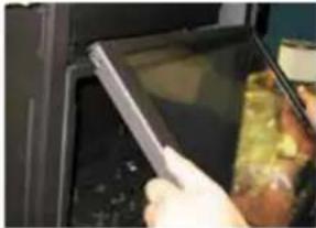
3) Remove all the logs if installed and set aside carefully.
4) Loosen the 4 screws securing the brackets that hold the existing back and both side panels in place.
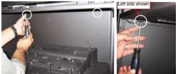
5) Remove the two back brackets and screws (set aside) first, then remove the back panel by lifting it up slightly, tilt it forward, then lift it out.
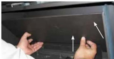
6) Remove the two side brackets and screws (set aside) - then remove the side panels by tilting the top in and lifting them out.

7) To install, do steps 6 to 1 in that order.
NOTE: When re-installing the back panel, ensure the bottop lip is tucked behind the rear log tray.


TROUBLESHOOTING GUIDE
| ALL WORK MUST BE CARRIED OUT BY A LICENSED/QUALIFIED TECHNICIANIt is critical that this appliance is earthed and that Active and Neutral are not crossed* Pilot light models only | ||
| SYMPTOM | CAUSE | SOLUTION |
| Unit does not operate(No ignition & No Fan) | No power supply (240V) to unit or control box | Check 240V power supply |
| Faulty ECS box | Replace ECS module & Cat 5 Cable | |
| Unit will not operate using remote control, but OK using manual control | Remote control not tuned into unit. | Tune remote control into unit |
| Remote is not tuning to the unit | Replace Remote control and or ECS module | |
| * Unit goes through ignition cycle,but pilot light does not igniteDirect Spark unitsIgniter sparks but main burner doesn't light | No gas to unit or fitting line has not been purged | Check gas supply or purge fitting line |
| * Blocked pilot | * Clean or replace pilot assembly | |
| Faulty ignition pack | Replace Ignition pack | |
| Ignitor earthing or sparking to incorrect location | Ensure sparker is in good condition, replace if necessary | |
| * Pilot light ignites but main burner does not ignite, igniter continues to spark for 10 seconds then goes to lock outDirect Spark unitsMain burner ignites but igniter continues to spark for 10 seconds then goes to lock out | Faulty sensor lead/ circuit | Check flame sensor is connected and not damaged |
| Crossed polarity, Faulty extension lead or power board | Check polarity at power point connection into heater and ECS control box | |
| Faulty Ignition Module | Replace Ignition module | |
| * Pilot light ignites but main burner does not ignite, igniter stop sparking and pilot flame stays on | No Gas to main burner | Check burner injector for blockage |
| Pressure switch not activating | Ensure Fan is running | |
| Clear any blockage in hose from pressure switch to fan. | ||
| Clean the fan | ||
| Replace Pressure switch | ||
| No power out of ignition module | Replace Ignition Module | |
TROUBLESHOOTING GUIDE
| Unit ignites, main burner becomes unstable, flame lifts off burner, unit goes into lockout | Incorrect burner pressure settings | Adjust burner pressure to correct setting (See Data plate) |
| Flue blocked, Incorrect flue installation or flue joints not sealed | Clear blocked flue, install flue correctly and seal all flue joints | |
| Burner aeration not correctly adjusted | Adjust burner aeration (See Unit Manual) | |
| Log set incorrectly installed | Install log set as per Owner's Manual | |
| Flue Restrictor not set correctly | Adjust Flue restrictor (See unit manual) | |
| Fan operates but no ignition sequence (no spark) | Unit ignition pack gone into lockout | Reset ignition pack by depressing black reset button while unit controls are in the "ON" position (fan running) |
| Carbon build up on glass/media/logs | Burner cracked | Replace burner |
| Log set / media incorrectly installed | Install log set / media as per owner's manual | |
| Aeration setting too far closed | Set aeration as per owner's manual | |
| Aeration blocked | Clean blockage at aeration shutter | |
| Flue restrictor not set correctly | Adjust flue restrictor as per owner's manual | |
| Partial blockage in flue | Clear blocked flue |
GAS APPLIANCE MAINTENANCE
In order for your Regency appliance to continue to provide comfort to your home periodic maintenance must be performed to ensure it is operating at peak efficiency. The items in the list should be checked by a licensed gas service technician during the annual service check. Your unit may require more frequent maintenance checks if you notice any changes in how it operates. Operational changes to look for can include, but are not limited to, extended start up time, increased fan noise, residue/carbon build up, white build up on the glass/firebox, increased operating noise etc. Should any of these or other conditions arise, discontinue use and schedule a service check with your local licensed gas technician. The list below shows items your licensed service technician will need to check and service at least annually.
Clean
- Glass
• Interior bricks / panels - Burner ports & burner air shutter
- Fan blades
- Log set
- Pilot orifices
- Pilot hood (change as needed)
- Flame sensor (electronic ignition models)
- Flame electrode
- Burner orifice
• Thermocouple (millivolt models)
• Thermopile (millivolt models)
Inspect
- Pilot assembly
- Burner
- Pressure relief gaskets/doors
- Flue connector gasket if present
- Door seal
- Firebox
- Venting
- Batteries (remote handheld, remote receiver, DC sparker, change as needed)
- Burner media (change as needed)
- Air shutter setting
- Wiring
Check
- Voltage on thermocouple/thermopile (millivolt models)
- Ohms reading on flame sense (electronic ignition models)
• Inlet/outlet fuel pressures as per rating plate
• Voltage/ohms readings on gas valve - Ohms reading to on/off switch circuit (Mili-volt models)
Gas Leak Tests
- Check main gas line connection to valve
- Check shut off valve connections
- Check connection at gas valve outlet
- Check connection at main burner orifice
- Check pilot fuel line at valve and at pilot assembly
ELECTRONIC COMPONENTS PARTS LIST
Note: Depending on the model, the diagram below may not be exactly as shown - for reference purposes only.
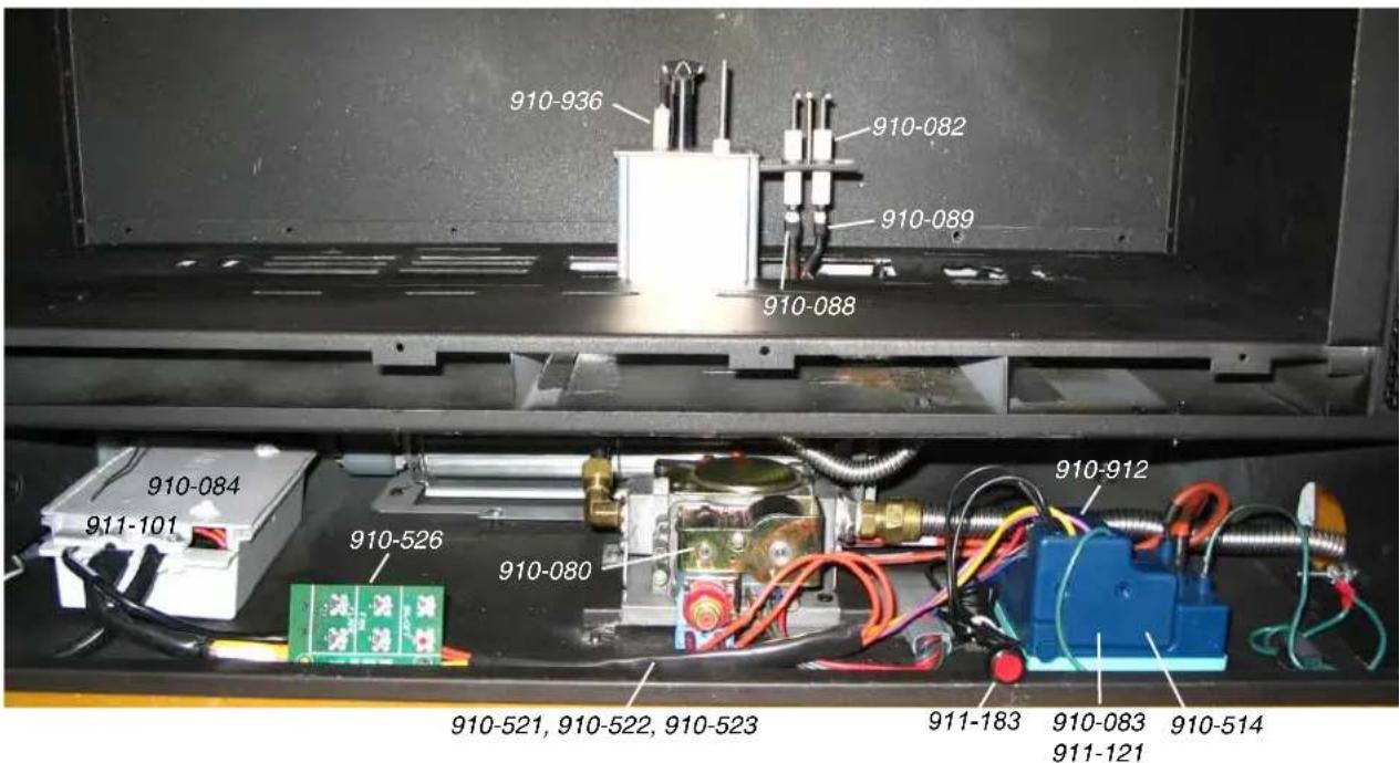
| FG38 F | G39 PG33 | PG36 / | PG36D | PG121/PG131 | GFI300L | DVI34L GF90 | OL/C GF150 | DL | ||
| 910-909 Fan Resistor | √ √ | √ √ √ | √ √ √ √ | |||||||
| 910-936 Intermittent Pilot | N/A | √ √ | √ √ | N/A | √ | √ | N/A | |||
| 911-146 Intermittent Pilot | N/A | N/A | N/A | N/A | N/A | √ | N/A | N/A | √ | |
| 910-082 Direct Spark Ignitor | √ | N/A | N/A | N/A | N/A | N/A | N/A | N/A | N/A | |
| 910-089 Flame Cable | √ | N/A | N/A | N/A | N/A | N/A | N/A | N/A | N/A | |
| 910-088 Spark Cable | √ | N/A | N/A | N/A | N/A | N/A | N/A | N/A | N/A | |
| 910-084 Control Box | √ √ | √ √ √ | N/A | √ | N/A | N/A | ||||
| 911-101 Control Box | N/A | N/A | N/A | N/A | N/A | √ | check | N/A | √ | |
| 910-527 Manual Control Switch | √ | √ | N/A | N/A | N/A | N/A | N/A | N/A | N/A | |
| 910-080 Valve | √ √ | √ √ √ √ √ √ √ √ √ √ √ √ √ √ √ √ √ √ √ √ √ √ √ √ √ √ √ √ √ √ √ √ √ √ √ √ √ √ √ √ √ √ √ √ √ √ √ √ √ √ √ ∞ √ √ √ √ √ √ √ √ √ √ √ √ √ √ √ √ √ √ √ √ √ √ √ √ √ √ √ √ √ √ √ √ √ √ √ √ √ √ √ √ √ √ √ √ √ √ √ √ √ ∶ √ √ √ √ √ √ √ √ √ √ √ √ √ √ √ √ √ √ √ √ √ √ √ √ √ √ √ √ √ √ √ √ √ √ √ √ √ √ √ √ √ √ √ √ √ √ √ √ √ ∕ √ √ √ √ √ √ √ √ √ √ √ √ √ √ √ √ √ √ √ √ √ √ √ √ √ √ √ √ √ √ √ √ √ √ √ √ √ √ √ √ √ √ √ √ √ √ √ √ √ ∜ √ √ √ √ √ √ √ √ √ √ √ √ √ √ √ √ √ √ √ √ √ √ √ √ √ √ √ √ √ √ √ √ √ √ √ √ √ √ √ √ √ √ √ √ √ √ √ √ √ ∤ √ √ √ √ √ √ √ √ √ √ √ √ √ √ √ √ √ √ √ √ √ √ √ √ √ √ √ √ √ √ √ √ √ √ √ √ √ √ √ √ √ √ √ √ √ √ √ √ √ ∭ √ √ √ √ √ √ √ √ √ √ √ √ √ √ √ √ √ √ √ √ √ √ √ √ √ √ √ √ √ √ √ √ √ √ √ √ √ √ √ √ √ √ √ √ √ √ √ √ √ ∦ √ √ √ √ √ √ √ √ √ √ √ √ √ √ √ √ √ √ √ √ √ √ √ √ √ √ √ √ √ √ √ √ √ √ √ √ √ √ √ √ √ √ √ √ √ √ √ √ √ ∮ √ √ √ √ √ √ √ √ √ √ √ √ √ √ √ √ √ √ √ √ √ √ √ √ √ √ √ √ √ √ √ √ √ √ √ √ √ √ √ √ √ √ √ √ √ √ √ √ √ ∪ √ √ √ √ √ √ √ √ √ √ √ √ √ √ √ √ √ √ √ √ √ √ √ √ √ √ √ √ √ √ √ √ √ √ √ √ √ √ √ √ √ √ √ √ √ √ √ √ √ ∨ √ √ √ √ √ √ √ √ √ √ √ √ √ √ √ √ √ √ √ √ √ √ √ √ √ √ √ √ √ √ √ √ √ √ √ √ √ √ √ √ √ √ √ √ √ √ √ √ √ ∬ √ √ √ √ √ √ √ √ √ √ √ √ √ √ √ √ √ √ √ √ √ √ √ √ √ √ √ √ √ √ √ √ √ √ √ √ √ √ √ √ √ √ √ √ √ √ √ √ √ ∖ √ √ √ √ √ √ √ √ √ √ √ √ √ √ √ √ √ √ √ √ √ √ √ √ √ √ √ √ √ √ √ √ √ √ √ √ √ √ √ √ √ √ √ √ √ √ √ √ √ ∯ √ √ √ √ √ √ √ √ √ √ √ √ √ √ √ √ √ √ √ √ √ √ √ √ √ √ √ √ √ √ √ √ √ √ √ √ √ √ √ √ √ √ √ √ √ √ √ √ √ ∩ √ √ √ √ √ √ √ √ √ √ √ √ √ √ √ √ √ √ √ √ √ √ √ √ √ √ √ √ √ √ √ √ √ √ √ √ √ √ √ √ √ √ √ √ √ √ √ √ √ ∥ √ √ √ √ √ √ √ √ √ √ √ √ √ √ √ √ √ √ √ √ √ √ √ √ √ √ √ √ √ √ √ √ √ √ √ √ √ √ √ √ √ √ √ √ √ √ √ √ √ ∎ √ √ √ √ √ √ √ √ √ √ √ √ √ √ √ √ √ √ √ √ √ √ √ √ √ √ √ √ √ √ √ √ √ √ √ √ √ √ √ √ √ √ √ √ √ √ √ √ √ ∵ √ √ √ √ √ √ √ √ √ √ √ √ √ √ √ √ √ √ √ √ √ √ √ √ √ √ √ √ √ √ √ √ √ √ √ √ √ √ √ √ √ √ √ √ √ √ √ √ √ ∫ √ √ √ √ √ √ √ √ √ √ √ √ √ √ √ √ √ √ √ √ √ √ √ √ √ √ √ √ √ √ √ √ √ √ √ √ √ √ √ √ √ √ √ √ √ √ √ √ √ ∟ √ √ √ √ √ √ √ √ √ √ √ √ √ √ √ √ √ √ √ √ √ √ √ √ √ √ √ √ √ √ √ √ √ √ √ √ √ √ √ √ √ √ √ √ √ √ √ √ √ ∧ √ √ √ √ √ √ √ √ √ √ √ √ √ √ √ √ √ √ √ √ √ √ √ √ √ √ √ √ √ √ √ √ √ √ √ √ √ √ √ √ √ √ √ √ √ √ √ √ √ ∸ √ √ √ √ √ √ √ √ √ √ √ √ √ √ √ √ √ √ √ √ √ √ √ √ √ √ √ √ √ √ √ √ √ √ √ √ √ √ √ √ √ √ √ √ √ √ √ √ √ ∆ (∑ 1) | ||||||||
| *N/A | (2) | (1) | (1) | (3) | N/A | (2) | N/A | N/A | ||
| N/A | N/A | √√ | √√√ | √√√ | √√√ | |||||
| 911-183 Reset Switch | N/A | √√ | √√√ | √√√ | √√√ | |||||
| 910-083 Ignition Module (1) | (1) | |||||||||
| 911-121 Ignition Module (2) | (2) | (2) | (2)(2) | (2) | (2)(2) | (2)(2) | ||||
| 910-514 Jumper Wire | N/A | √√ | √√√ | √√√ | √√√ | |||||
| 910-935 Manual Control Switch | N/A | N/A | √√ | √√ | N/A | N/A | N/A | |||
MAIN ASSEMBLY
Part #
Description
Part #
| 1 337-574/P Valve Assembly - NG |
| 1 337-576/P Valve Assembly - LP |
| 2 910-080 Gas Valve NG/LP 845 Sigma 1/2 in NPT 0.845.088 |
| 3 910-936 Pilot Assembly - NG 3 Flame 199.008 |
| 3 910-947 Pilot Assembly - LP 3 Flame |
| 4 904-240 Burner Orifice #37 - NG |
| 4 904-390 Burner Orifice #52 - LP |
| 4 904-345 Burner Orifice #53-ULPG |
| 5 320-518 Flue Adaptor Assembly |
| 6 420-048 Flue Adaptor Gasket |
| 7 336-059 Log Tray Rear |
| 8 336-535 Burner Assembly NG/LP |
| 9 337-013 Faceplate Mounting Bracket Left |
| 10 337-014 Faceplate Mounting Bracket Right |
| 11 911-121 Module SIT 230V (DV) 0.579.204 |
Description
| 12 911-101 Control Box ECS III |
| 13 402-526 Grate/Diffuser Assembly |
| 14 425-017 Side Panel LH/RH (Each) |
| 15 336-061 Rear Panel Back |
| 16 336-519/P Fan Assembly Complete |
| 17 910-169/P Fan 240 Volt Transflow 2 Speed |
| 18 911-310 Pressure Switch ES2371-1092 |
| 19 337-036 Door Frame Only |
| 20 948-247 Handle Spring Lever |

MAIN ASSEMBLY
| Part # | Description | Part # | |
| N/S 948-042 | Bottom Black Hinge (Each) | ||
| N/S 904-603 | Clamp Hose Stainless Steel | ||
| N/S 948-223 | Logo Plate Plastic Regency/Flame Silver | ||
| N/S 910-036 | Pilot Orifice - NG | ||
| N/S 910-037 | Pilot Orifice - LP | ||
| N/S 910-096 | 3 Flame Pilot Hood | ||
| N/S 911-137 | 3 way Pilot Hood Clip | ||
| N/S 911-002 | Flame Electrode | ||
| N/S 911-037 | Flame Sensor | ||
| N/S 910-432 | Pilot Tubes With Nuts | ||
| N/S 932-012 | Gas Outlet Tubing SS Flexible 305 mm Long | ||
| N/S 936-170 | Gasket Orifice | ||
| N/S W840 | 470 Gasket Pilot Assembly | ||
| N/S 904-599 | Fitting Elbow 90 Degree | ||
| N/S 904-658 | Inlet Flex Line Gas SS Steel 710 mm Long | ||
| N/S 904-798 | Fitting Elbow 90 Deg 1/2x3/8 Tube 69-6D | ||
| N/S 904-911 | Fitting Connector 1/2 MIP x 1/2 Flare | ||
| N/S 905-049 | Adaptor Male Dormont 90-2031-BSP | ||
| N/S 904-529 | Allen Key 5/32" | ||
| N/S 336-001 | Gasket - Valve Tray | ||
| N/S 910-522 | Wire Harness ECS IP FG37/FG39 | ||
| N/S 910-514 | Wire Jumper SIT Ignition Module | ||
| N/S 910-912 | Wire Harness Module To Valve | ||
| N/S 911-113 | Switch On/Off W/CAT 5 Cable 915 mm Long(105C) | ||
| N/S 910-896 | Wire High Temp To Power Cord | ||
| N/S 910-780 | Wire SIT Valve Wire | ||
| N/S 402-935 | Log Set | ||
| N/S 402-572 | Ember Set | ||
| N/S 946-669 | Ember Platinum Bright (PBE) 1 gram | ||
| N/S 910-692 | Wire Ground 24 inch (Green) Fan | ||
| N/S 910-504 | Wire Ground ECS (Green) Module | ||
| N/S 910-714 | Power Cord 240 Volts |
Description
| N/S 910-909 Resistor Fan B | CS SQHG-20W |
| N/S 910-996 Wire Fan Resistor Jumper | |
| N/S 911-047 Silicone Tubing | 0.313 OD x 0.187 ID |
| N/S 911-183 Switch Pushbutton | tton Reset Blk SPST-NC 1A |
| N/S 911-100 Remote Control | ECS III w/WallMount Bracket |
| N/S 940-307/P Replacement | Glass Includes Gasket |
| N/S 936-155 Glass Gasket | Tadpole Tape (178MM Required) |
| N/S 904-691 Glass Clip-U (Each) 4 Per Unit | |
| N/S 948-025 Spring Door Extension | |
| N/S 948-045 Chain Jack #12 | |
| N/S 337-030 Mesh Glass Guard | |
FACEPLATE ASSEMBLY
PART # 337-914
| 1 * Faceplate | ||
| 2 * Safety Screen | ||
| 3 * Lip | ||
| 4 * Mesh Bottom Screen | ||
| 5 948-042 Hinge and Hnge Support | ||
| 6 * Bottom Door | ||
*Not available as a replacement part

OTHER OPTIONAL ACCESSORIES
337-968 Conversion Kit LP/ULPG
337-918 Spacer
Limited Lifetime Warranty
FPI Fireplace Products International Ltd. ("the manufacturer") through its wholly owned subsidiary, Fireplace Products Australia Pty Ltd (for Australia and New Zealand customers) and sold under the Regency® brand of fireplace products (collectively referred to herein as "FPI"), extends this Limited Lifetime Warranty to the original purchaser of this appliance provided the product remains in the original place of installation. The items covered by this limited warranty and the period of such coverage is set forth in the table below.
Some conditions apply (see below).
The policy is not transferable, amendable or negotiable under any circumstances.
| Indoor Gas Products Warranty Coverage Parts and Labor | Part Lifetime | 5 years | 2 years | 1 year | Supplier Warranty | Labor Coverage (Years) |
| Firebox and Heat Exchanger | √ | 3 | ||||
| Steel Burner Tube | √ | 3 | ||||
| Glass Thermal breakage only | √ | 3 | ||||
| All Surrounds/Inlays Finishes | √ | 3 | ||||
| Brick Panels/Log sets/Ceramic Burners | √ | 3 | ||||
| All Castings | √ | 3 | ||||
| Valve assembly and all gas control components (Pilot assembly, flame sensors, Spark Electrode, Pilot Tubing, Orifices, Thermocouple, Thermopile) | √ | 2 | ||||
| All Other Electrical components with the exception of WIFI Dongle (Ignition Control Boards, Wiring, Switches, Fans, Fan Control Module, Battery Pack, Remote Control Systems) | √ | 1 | ||||
| Enamel Panels | √ | 1 | ||||
| Venting/Venting Components | √ | 1 | ||||
| All Stainless steel surrounds | √ | 1 | ||||
| All Firebox Media (Crystals, Fire beads, Volcanic, Ceramic & Spa Stones) | √ | 1 | ||||
| All hardware | √ | 1 | ||||
| Mesh/Glass Safety Barriers | √ | 1 | ||||
| Accent Light Bulbs | √ | 1 | ||||
| Glass (Crazing) | √ | 1 | ||||
| WIFI Dongle (Applicable Models) | √ | 1 |
After the original warranty coverage for any of the parts above have expired, any repair and/or replacement parts purchased by the consumer from FPI or through an accredited distributor or dealer will carry a ninety (90) day warranty (valid only with an original copy of the tax invoice). No labor coverage is included with any repair and/or replacement part.
Replacement parts are limited to one per warranty term.
Conditions:
Warranty protects against defect in manufacture or FPI factory assembled components only, unless herein specified otherwise. This warranty will only apply to those products which are acquired at the time of this warranty being effective. FPI will not be liable for any damage or loss that falls outside the scope of the warranty.
Any part(s) found to be defective during the warranty period as outlined above will be repaired or replaced at FPI's option through an accredited distributor, dealer or pre-approved and assigned agent provided that the defective part is returned to the distributor, dealer or agent for inspection if requested by FPI. Alternatively, FPI may at its own discretion fully discharge all of its obligations under the warranty by refunding the verified purchase price of the product to the original purchaser. The purchase price must be confirmed by an original copy of the tax invoice.
The authorised selling dealer, or an alternative authorised FPI dealer if pre-approved by FPI, is responsible for all in-field diagnosis and service work related to all warranty claims. This warranty does not cover dealer travel costs for diagnostic or service work. Dealers may charge homeowner for travel and additional time. Check with your selling dealer in advance for any costs to you when arranging a warranty call. FPI is not responsible for results or costs of workmanship of unauthorised FPI dealers or agents in the negligence of their service work. Additional service fees may apply if you are seeking warranty service from a dealer other than the dealer from whom you originally purchased the product.
At all times FPI reserves the right to inspect reported complaints on location in the field claimed to be defective and determine whether the warranty will apply prior to processing or authorising of any claim. Failure to allow this upon request will void the warranty.
All warranty claims must be submitted by the dealer servicing the claim, including an original copy of the tax invoice (proof of purchase by you). All claims must be complete and provide full details as requested by FPI to receive consideration for evaluation, including proof of maintenance records. Incomplete claims may be rejected. FPI has absolute discretion to assess and determine any warranty claim and may accept or reject a claim as it considers appropriate. Any part or parts of the unit found to be defective will be repaired or replaced at FPI's option, through an accredited distributor or service agent provided that the defective part be returned to the distributor or agent, Transportation Prepaid, if requested. It is the general practice of FPI to charge for larger, higher priced replacement parts and issue credit once the replaced component has been returned to FPI and evaluated for manufacturer defect.
If a consumer has a unit installed outside an accredited distributor, dealer or pre-approved service agent's service area, or the closest approved service agent is situated more than thirty (30) kilometres from the installation, FPI is not obliged to arrange warranty repairs or shipping/transportation costs. In these cases, the consumer must arrange warranty service with its selling dealer, and shipping, travel and/or additional labor charges will apply.
Unit must be installed according to all manufacturers' instructions as per the manual.
All Local and National required codes must be met.
The installer is responsible to ensure the unit is operating as designed at the time of installation.
The original purchaser is responsible for annual maintenance of the unit, as outlined in the owner's manual. As outlined below, the warranty may be voided due to problems caused by lack of maintenance. Annual maintenance records should be retained.
Repair/replacement parts purchased by the consumer from FPI after the original coverage has expired on the unit will carry a 90 day warranty, valid with a receipt only. Any item shown to be defective will be repaired or replaced at our discretion. No labor coverage is included with these parts.
Exclusions:
This Limited Lifetime Warranty does not extend to paint, rust or corrosion of any kind due to a lack of maintenance or improper venting, combustion air provision, corrosive chemicals (i.e. chlorine, salt, air, etc.), door or glass gasket.
Malfunction, damage or performance based issues as a result of environmental conditions, location, chemical damages, downdrafts, installation error, installation by an unqualified installer, incorrect chimney components (including but not limited to cap size or type), operator error, abuse, misuse, use of improper fuels, accidents, lack of regular maintenance and upkeep, acts of God, weather related problems from hurricanes, tornadoes,
earthquakes, floods, lightning strikes/bolts or acts of terrorism or war, which result in malfunction of the appliance are not covered under the terms of this Limited Lifetime Warranty.
FPI has no obligation to enhance or modify any unit once manufactured (i.e. as products evolve, field modifications or upgrades will not be performed on existing appliances).
Any unit showing signs of neglect or misuse will not be covered under the terms of this warranty policy and may void this warranty. This includes units with rusted or corroded fireboxes which have not been reported as rusted or corroded within three (3) months of installation/purchase. Any alteration to the unit which causes sooting or carboning that results in damage to the exterior fascia or over firing that can cause component or firebox/heat exchanger failure will not be covered by this warranty.
Units which show evidence of being operated while damaged, or with problems known to the purchaser and causing further damages will void this warranty.
Units where the serial no. has been altered, deleted, removed or made illegible will void this warranty.
Minor movement, expansion and contraction of the steel is normal and is not covered under the terms of this warranty.
Freight damages for products or parts are not covered under the terms of the warranty.
Porcelain/Enamel: Absolute perfection is neither guaranteed nor commercially possible. Any chips must be reported and inspected by the authorised selling dealer within three (3) days of installation. Any damage of this type not reported after this time period will be subject to rejection and any related warranty will not apply.
Special Finishes: Expect some changes in color as the product "ages" with constant heating and cooling. The manufacturer warranty does not cover tarnishing, changing colors and/or marks (i.e. finger prints, etc.) after the purchase of the product. Damage from the use of abrasive cleaners is not covered by warranty.
Products made or provided by other manufacturers and used in conjunction with the FPI appliance without prior authorisation from FPI may void this warranty.
INCORRECT INSTALLATION OR GAS PRESSURE SETTINGS ARE NOT COVERED BY WARRANTY. A SERVICE OR CALLOUT FEE WILL BE CHARGED IN THESE CIRCUMSTANCES.
Limitations of Liability:
1. Exclusion of implied terms
The customer may have the benefit of consumer guarantees under the Australian Consumer Law. To the maximum extent permitted by law, all terms, conditions or warranties that would be implied into this Warranty or in connection with the supply of any goods or services by the supplier under law or statute or custom or international conventions are excluded.
2. Limitation of liability
(a) To the maximum extent permitted by law and subject to clauses 1 and 3, the supplier's total liability arising out of or in connection with its performance or its obligations pursuant to this Warranty, or arising out of or in connection with the supply of specific goods or services (including pursuant to or for breach of this Warranty, under statute, in equity or for tort, including negligent acts or omissions) is limited as follows: (i) the supplier shall have no liability to the customer for any Consequential Loss; (ii) without limiting the effect of clause 2(a)(i), the supplier's total aggregate liability for Loss, however arising, shall not exceed the GST exclusive aggregate price paid by the customer to the supplier for the specific goods or services that gave rise to the Loss in question.
(b) The limitations and exclusions in this sub-clause do not apply to the extent that any Loss is directly attributable to: (i) the personal injury or death caused by the supplier's default, breach of this Warranty or negligence; or (ii) fraud by the supplier.
(c) Each party must take reasonable steps to mitigate any Loss it suffers or incurs.
3. Limitation of liability under Australian Consumer Law Guarantees
(a) To the extent that goods supplied by the supplier are not goods of a kind ordinarily acquired for personal, domestic or household use and the customer is deemed to be a consumer for the purposes of section 64A of the Australian Consumer Law, the customer agrees that the supplier's liability for a failure to comply with a consumer guarantee that the customer may have a benefit under the Australian Consumer Law (other than a guarantee under sections 51 (title), 52 (undisturbed possession) and 53 (undisclosed securities)), is limited to, at the option of the supplier, one or more of the following: (i) replacement of the goods or the supply of equivalent goods; (ii) the repair of the goods; (iii) the payment of the cost of replacing the goods or of acquiring equivalent goods; or (iv) equivalent goods; or (v) the payment of the cost of having the goods repaired.
(b) To the extent that services supplied by the supplier are services other than services of a kind ordinarily acquired for personal, domestic or household use or consumption, the supplier's liability for failure to comply with a consumer guarantee that the customer may have the benefit of is limited to, at the option of the supplier: (i) the supply of the services again; or (ii) the payment of the cost of having the services supplied again.
4. Subject to Change
This Limited Warranty is given at the time of sale and purchase of the relevant fireplace product. The terms of this Limited Warranty may be amended from time to time by FPI in accordance with changes to business practices, consumer laws or other legal requirements. The rights and protections granted under the Limited Warranty are those in force in relation to a fireplace product at the time and in the place of sale of that product, and only those terms will be applicable in respect of that product.
5. Severability
Any term of this Limited Warranty that is invalid or unenforceable in any jurisdiction is to be read down for the purposes of that jurisdiction, if possible, so as to be valid and enforceable, and is otherwise capable of being severed to the extent of the invalidity or unenforceability, without affecting the remaining provisions of this Limited Warranty or affecting the validity or enforceability of that provision in any other jurisdiction.
6. Definitions
For purposes of clauses 1, 2 and 3:
(a) Consequential Loss means loss of expected savings, loss of use, loss of opportunity, loss of profit, loss of revenue, increased financing costs, loss arising from delay, or any consequential, special or indirect loss or damage, whether or not the possibility or potential extent of the loss or damage was known or foreseeable, and whether arising from a claim under indemnity, contract, tort (including negligence), statute or otherwise.
(b) Loss means any expense, cost or damage of any kind and includes Consequential Loss and a fine or penalty imposed by a statutory or other authority.
How to Obtain Warranty Service:
Customers should contact the authorised selling dealer to obtain warranty service. In the event the authorised selling dealer is unable to provide warranty service, please contact FPI by mail at the address listed below. Please include your name, address, purchase date, selling dealer, serial #, type of unit, a brief description of the problem, email and telephone contact information, and a copy of your original tax invoice. A representative will contact you to make arrangements for an inspection and/or warranty service. (See below for Western Australia and/or New Zealand)
Please note Fireplace Products Australia Pty Ltd does not provide installation services.
Fireplace Products Australia Pty Ltd
99 Colmans Road
Dandenong, VIC
Australia, 3175
Phone: +61 3 9799 7277
Fax: +61 3 9799 7822
To obtain warranty service in Western Australia and/or New Zealand, please contact one of our authorised distributors in those areas:
Western Australia:
Air Group Australia
28-30 Division St.
Welshpool, WA
Australia, 6106
Phone: (08) 9350 2200
Fax: (08) 9353 4225
New Zealand:
Aber Holdings Ltd
PO Box 10095
Te Rapa, Hamilton
New Zealand, 3241
Freephone: 0800 161 161
Product Registration and Customer Support:
Thank you for choosing a Regency Fireplace. Regency strives to be a world leader in the design, manufacture, and marketing of hearth products. To provide the best support for your product, we request that you complete a product registration form at http://www.regency-fire.com.au/Customer-Care/Warranty-Registration.aspx within ninety (90) days of purchase.

REGENCY
FIREPLACE PRODUCTS
Product Registration and Customer Support:
Thank you for choosing a Regency Fireplace. Regency strives to be a world leader in the design, manufacture, and marketing of hearth products. To provide the best support for your product, we request that you complete a product registration form found on our Web Site under Customer Care within ninety (90) days of purchase.
For purchases made in CANADA or the UNITED STATES:
http://www.regency-fire.com/Customer-Care/Warranty-Registration.aspx
For purchases made in AUSTRALIA:
http://www.regency-fire.com.au/Customer-Care/Warranty-Registration.aspx
You may also complete the warranty registration form below to register your Regency Fireplace Product and mail and/or fax it back to us, and we will register the warranty for you. It is important you provide us with all the information below in order for us to serve you better.
Warranty Registration Form (or Register online immediately at the above Web Site):
| Warranty Details | |
| Serial Number (required): | |
| Purchase Date (required) (mm/dd/yyyy): | |
| Product Details | |
| Product Model (required): | |
| Dealer Details | |
| Dealer Name (required): | |
| Dealer Address: | |
| Dealer Phone #: | |
| Installer: | |
| Date Installed (mm/dd/yyyy): | |
| Your Contact Details (required) | |
| Name: | |
| Address: | |
| Phone: | |
| Email: | |
For purchases made in CANADA:
For purchases made in the UNITED STATES:
For purchases made in AUSTRALIA:
FPI Fireplace Products
Fireplace Products US, Inc.
Fireplace Products Australia Pty
International Ltd.
PO Box 2189 PMB 125
Ltd
6988 Venture St.
Blaine, WA
99 Colmans Road
Delta, British Columbia
United States, 98231
Dandenong, VIC
Canada, V4G 1H4
Australia, 3175
Phone: 604-946-5155
Phone: 604-946-5155
Phone: +61 3 9799 7277
Fax: 1-866-393-2806
Fax: 1-866-393-2806
Fax: +61 3 9799 7822
For fireplace care and tips and answers to most common questions please visit our Customer Care section on our Web Site. Please feel free to contact your selling dealer if you have any questions about your Regency product.
IMPORTANT: A certificate of compliance or equivalent by an authorised installer must be obtained on commissioning of appliance to obtain warranty.
Installer: Please complete the following information
Dealer Name & Address:
Installer:
Phone #: ____
Date Installed: ____
Serial #:
- OWNERS & INSTALLATION
- MANUAL
- LISTINGS AND CODE APPROVALS
- REGENCY®
- FIREPLACE PRODUCTS
- DVI34L GAS INBUILT
- PLEASE KEEP THESE INSTRUCTIONS FOR FUTURE REFERENCE
- REGENCY
- GAS INBUILT FIREPLACE
- TO THE NEW OWNER
- PAIRING YOUR REMOTE CONTROL
- FAN OPERATION
- WARNING
- RELEASE
- UNIT DIMENSIONS - FLUSH INSTALL
- UNIT DIMENSIONS - WITH SPACER
- OWNER'S INFORMATION
- UNIT DIMENSIONS
- DATA BADGE
- INSTALLATION
- OPERATING INSTRUCTIONS
- MAINTENANCE
- PARTS LIST
- WARRANTY
- REGENCY GAS FIREPLACE
- GAS TYPE
- NG
- PROPANE ULPG
- DVI34LNG
- IMPORTANT MESSAGE
- FOR YOUR SAFETY
- MATERIALS REQUIRED
- BEFORE YOU START
- INSTALLATION CHECKLIST
- MINIMUM FIREPLACE OPENING
- CLEARANCES TO COMBUSTIBLES
- GAS CONNECTION
- GAS CONNECTION WARNING: ONLY PERSONS LICENSED TO WORK WITH GAS PIPING MAY MAKE THE NECESSARY GAS CONNECTIONS TO THIS APPLIANCE
- FLUEING
- WARNING DO NOT USE AN UNLINED MASONRY CHIMNEY AS THE FLUE FOR THIS APPLIANCE. THE APPLIANCE MUST NOT CONNECT TO A CHIMNEY FLUE SERVING A SEPARATE SOLID FUEL BURNING APPLI- ANCE AND MUST NOT BE TERMINATED TO THE OUTDOORS
- FLUE LINER INSTALLATION
- GAS PIPE PRESSURE TESTING
- S.I.T. VALVE DESCRIPTION
- INSTALLATION IN MASONRY OR ZERO CLEARANCE CHIMNEY
- AERATION SETTINGS
- CONVERSION KIT #337-968 FROM NG TO PROPANE/ULPG MODEL
- LOG SET INSTALLATION
- GLASS DOOR INSTALLATION
- STANDARD FLUSH DOOR
- FACEPLATE & SAFETY SCREEN INSTALLATION
- OPTIONAL SPACER INSTALLATION (PART #337-918)
- FINAL CHECK
- CAUTION
- WIRING
- LIGHTING INSTRUCTIONS
- SHUTDOWN INSTRUCTIONS
- FIRST FIRE
- DO NOT ATTEMPT TO CLEAN THE GLASS WHILE IT IS STILL HOT
- DO NOT BURN THE APPLIANCE WITHOUT THE GLASS FRONT IN PLACE
- REMOTE CONTROL
- SUMMARY OF CONTROLS
- ON/OFF BUTTON
- FLAME
- FAN
- FAN MUST BE RUNNING AT ALL TIMES WHEN THE UNIT IS IN OPERATION
- ADJUSTING FLAME HEIGHT
- MANUAL ON/OFF CONTROL
- COPY OF LIGHTING INSTRUCTION PLATE
- FOR YOUR SAFETY READ BEFORE LIGHTING
- TO TURN OFF GAS APPLIANCE
- NORMAL OPERATING SOUNDS OF GAS APPLIANCES
- BLOWER
- BURNER TRAY
- GAS CONTROL VALVE
- UNIT BODY/FIREBOX
- RESETTING THE UNIT
- MAINTENANCE INSTRUCTIONS
- LOG REPLACEMENT
- DOOR GLASS REPLACEMENT
- FLUSH GLASS REPLACEMENT
- GLASS GASKET
- FAN MAINTENANCE
- TO REMOVE FAN
- VALVE ASSEMBLY REPLACEMENT
- INNER PANEL REMOVAL AND INSTALLATION
- GAS APPLIANCE MAINTENANCE
- CLEAN
- INSPECT
- CHECK
- GAS LEAK TESTS
- ELECTRONIC COMPONENTS PARTS LIST
- MAIN ASSEMBLY
- FACEPLATE ASSEMBLY
- PART # 337-914
- LIMITED LIFETIME WARRANTY
- CONDITIONS
- EXCLUSIONS
- LIMITATIONS OF LIABILITY
- EXCLUSION OF IMPLIED TERMS
- LIMITATION OF LIABILITY
- LIMITATION OF LIABILITY UNDER AUSTRALIAN CONSUMER LAW GUARANTEES
- SUBJECT TO CHANGE
- SEVERABILITY
- DEFINITIONS
- HOW TO OBTAIN WARRANTY SERVICE
- FIREPLACE PRODUCTS AUSTRALIA PTY LTD
- AIR GROUP AUSTRALIA
- ABER HOLDINGS LTD
- PRODUCT REGISTRATION AND CUSTOMER SUPPORT
Brand : Regency
Model : DVi34L
Category : Heating