
GS-6500IE - Generator Gentrax - Free user manual and instructions
Find the device manual for free GS-6500IE Gentrax in PDF.


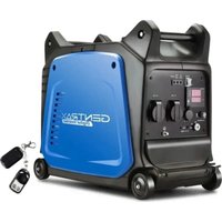
| Product Type | Portable Generator |
| Model | GS-6500IE |
| Brand | Gentrax |
| Rated Power (Watts) | 6500 |
| Peak Power (Watts) | 8125 |
| Fuel Type | Gasoline |
| Engine Type | 4-Stroke, OHV, Single Cylinder |
| Engine Displacement | 389 cc |
| Starting System | Electric & Recoil |
| Output Voltage | 120V/240V |
| Outlets | 2x 120V GFCI, 1x 240V L14-30R, 1x 12V DC |
| Fuel Tank Capacity | 6.6 gallons (25 L) |
| Run Time at 50% Load | 12 hours |
| Noise Level (at 7m) | 72 dB(A) |
| Dimensions (L x W x H) | 27 x 22 x 22 inches |
| Weight | 125 lbs (56.7 kg) |
| Features | Electric start, low oil shut-off, overload protection, CO detector, wheel kit |
| Maintenance | Change oil every 50 hours; clean/replace air filter; spark plug annually |
| Safety | GFCI outlets, automatic voltage regulator, carburetor heater |
| Spare Parts & Repairability | Replaceable spark plug, air filter, oil filter, fuel filter; service manual available |
Frequently Asked Questions - GS-6500IE Gentrax
User questions about GS-6500IE Gentrax
0 question about this device. Answer the ones you know or ask your own.
Ask a new question about this device
Download the instructions for your Generator in PDF format for free! Find your manual GS-6500IE - Gentrax and take your electronic device back in hand. On this page are published all the documents necessary for the use of your device. GS-6500IE by Gentrax.
USER MANUAL GS-6500IE Gentrax
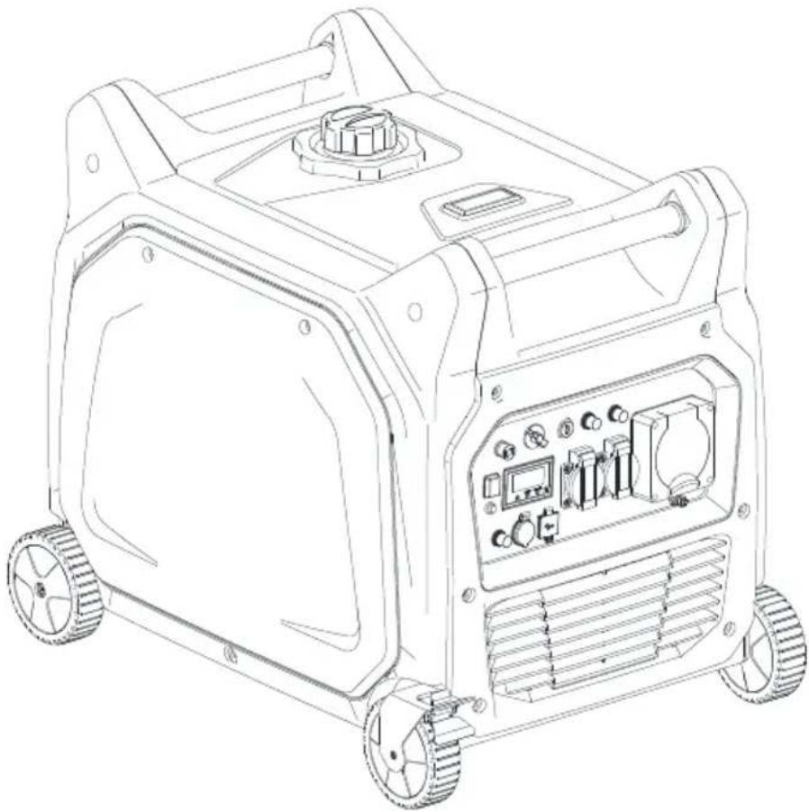
GASOLINE INVERTER GENERATOR USER'S MANUAL
natural_image
Line drawing of a portable electricity generator with wheels and control panel (no text or symbols)
IMPORTANT — Please make certain that persons who are to use this equipment thoroughly read and understand this user's manual prior to operation
INTRODUCTION
Thank you for purchasing this Inverter Generator. Before attempting to use this product, please read this manual thoroughly and follow the instructions carefully. In doing so you will ensure the safety of yourself and that of others around you, and you can look forward to your purchase giving you long and satisfactory service.
CONTENTS
SAFETY INFORMATION......2
CONTROL FUNCTION .... 3
- Never operate the engine in a dosed area or it may cause unconsciousness and death within a short time. Operate the engine in a well ventilated area.
FUEL IS HIGHLY FLAMMABLE AND POISONOUS
● Always turn off the engine when refueling
● Never refuel while smoking or in the vicinity of an open flame.
● Take care not to spill any fuel on the engine or muffler when refueling.
- If you swallow any fuel, inhale fuel vapor, or allow any to get in your eyes, see your doctor immediately. If any fuel spills on your skin or clothing, immediately wash with soap and water and change your clothes.
- When operating or transporting the machine, be sure it is kept upright. If it tilts, fuel may leak from the carburetor or fuel tank.
ENGINE AND MUFFLER MAY BE HOT
● Place the machine in a place where pedestrians or children are not likely to touch the machine.
● Avoid placing any flammable materials near the exhaust outlet during operation.
- Keep the machine at least 1 m (3 ft) from buildings or other equipment, or the engine may overheat.
● Avoid operating the engine with a dust cover.
- Be sure to carry the generator only by its carrying handle.
● Put the machine on the flat ground, for the machine eliminating heat freely.
ELECTRIC SHOCK PREVENTION
● Never operate the engine in rain or snow.
● Never touch the machine with wet hands or electrical shock will occur.
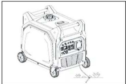
● Be sure to ground (earth) the generator.
NOTE:
Use ground (earth) lead of sufficient current capacity.
Diameter: 0.12mm (0.005 in)/ampere
EX: 10 Ampere -1.2mm (0.055 in)

natural_image
Line drawing of a portable electricity generator with wheels and control panel (no text or symbols)CONNECTION NOTES
● Avoid connecting the generator to commercial power outlet.
● Avoid connecting the generator in parallel with any other generator.
CONTROL FUNCTION
(1) Spark plug
(4) Fuel filter
(7) Muffler
(10) Brake lever
(13) Oil drain plug
(16) Engine switch
(19) Ground (earth) terminal
(22) DC 12V receptacle
(25) Output reset
(2) Fuel tank
(5) Carrying handle
(8) Battery
(11) Wheel
(14) Choke rod
(17) AC protector 15A
(20) AC receptacle 15A
(23) DC protector
(26) Economy control switch
(3) Fuel tank cap
(6) Fuel level gauge
(9) Air filter
(12) Oil filler cap
(15) Fuel cock
(18) Australia industrial socket 30A
(21) USB Output
(24) Data display instrument
(27) Remote control


OIL WARNING SYSTEM
When the oil level falls below the lower level, the engine stops automatically. Unless you refill with oil, the engine will not start again.
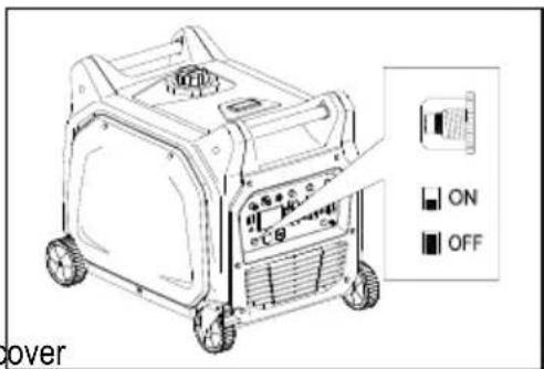
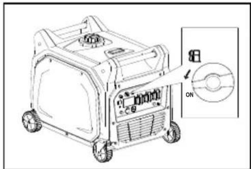
ENGINE SWITCH
The engine switch controls the ignition system.
① RUN
Ignition circuit is switched on. The engine can be started.
② STOP
Ignition circuit is switched off. The engine will not run.
③ START
Starting circuit is switched on. The starter motor starts.
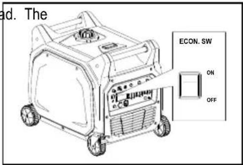
ECONOMY CONTROL SWITCH
When the economy control switch is turned ON, the economy control unit control the engine speed according to the connected load. results are better fuel connection and less noise.
DC CIRCUIT PROTECTOR
The DC circuit protector turns off automatically when the load exceeds the generator rated output.
CAUTION:
- Reduce the load to within specified generator rated output if the DC circuit protector turn off.
OUTPUT RESET
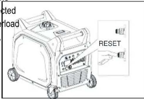
Push reset button for continuous 2 seconds, the generator will recover
the AC output when the generator stop AC output under overload protect.
NOTE:
Please reduce the load of generator to ensure that the total load is within the rated power.

flowchart
graph TD
    A["Top 3 Box"] --> B["Top 2 Box"]
    B --> C["Bottom 3 Box"]
    C --> D["Bottom 2 Box"]
    D --> E["Bottom 1 Box"]
    style A fill:#f9f,stroke:#333
    style B fill:#f9f,stroke:#333
    style C fill:#f9f,stroke:#333
    style D fill:#f9f,stroke:#333
    style E fill:#f9f,stroke:#333


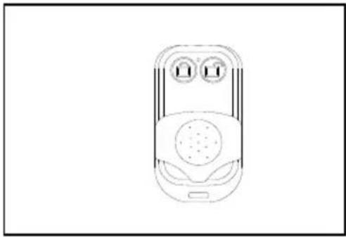
REMOTE CONTROL SWITCH
The remote control switch controls the ignition system
①

The starter motor starts.
②

The engine will not run.
BRAKE LEVER
The function of brake lever is preventing generator moving.
① Brake lever is not working, generator can move.
② Brake lever is working, generator can't move.
FUEL COCK
The fuel cock is used to supply fuel from the tank to the carburetor.
DATA DISPLAY INSTRUMENT


FAULT Defects or Overloads with red light on
OUTPUT Normal Running with green light on
II
Mode Selections: V1→A1→V2→A2→VA→Total Running Time →Current Running Time
natural_image
Line drawing of a mobile phone with two circular buttons and a speaker grille (no text or symbols)


PRE-OPERATION CHECK
NOTE:
- Pre-operation checks should be made each time the generator is used.
CHECK ENGINE FUEL
● Make sure there is sufficient fuel in the tank.
- If fuel is low, refill with unleaded automotive gasoline.
- Be sure to use the fuel filter screen on the fuel filter neck.
● Recommended fuel: Unleaded gasoline.
● Fuel tank capacity: 18.5 L.
WARNING:
● Do not refill tank while engine is running or hot.
- Close fuel cock before refueling with fuel.
- Be careful not to admit dust, dirt, water or other foreign objects into fuel.
- Do not fill above the top of the fuel filter or it may overflow when the fuel heats up later and expands.
● Wipe off spilt fuel thoroughly before starting engine.
- Keep open flames away.
CHECK ENGINE OIL
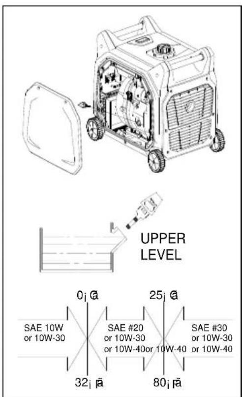
Make sure the engine oil is at the upper level of the oil filler hole. Add oil
as necessary.
- Remove oil filler cap and check the engine oil level.
- If oil level is below the lower level line, refill with suitable oil to upper level line. Do not screw in the oil filler cap when checking oil
● Change oil if contaminated.
Oil capacity: 1.1 L
● Recommended engine oil:
API Service SJ


GROUND (Earth)
Make sure to ground (earth) the generator.
CONNET BATTERY
- Loosen the screw and remove the battery cover.
- Clamp the red wire to the positive (+) terminal and the black wire to the negative (-) terminal of the battery. Do not reverse these positions.
- Be sure the battery is installed on the battery mount tray securely.
● Install the cover and tighten the screw.
NOTE:
● Recommended battery: 12V18AH.
natural_image
Line drawing of a portable gas generator with wheels and control panel (no text or symbols)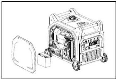
natural_image
Technical line drawing of a portable gas generator with open casing and internal components (no text or symbols)OPERATION
NOTE:
● The generator has been shipped without engine oil. Fill with oil or it will not start.
- Do not tilt the generator when adding engine oil. This could result in overfilling and damage to the engine.
natural_image
Line drawing of a portable gas generator with wheels and control panel, showing internal components and a close-up inset (no text or symbols)STARTING THE ENGINE
NOTE:
● Before starting the engine, do not connect the electric apparatus.

A Electric start
- Turn the fuel cock lever to the ON position.
- Pull out choke rod to the CHOKE position.
- Turn the engine switch to the START position.

-
Turn the engine switch to the RUN position.
-
Push choke rod to the RUN position.
-
Warm up the engine without a load for a few minutes.
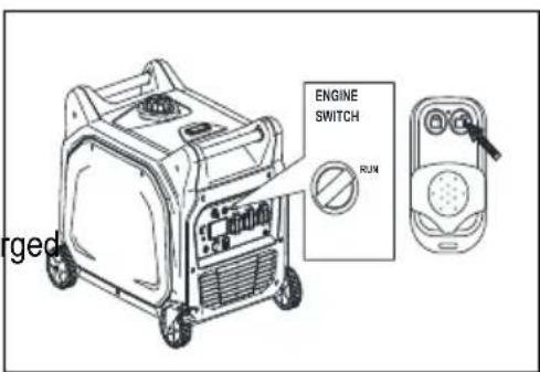
B Remote start
- Please make sure the fuel shutoff valve to the ON position, the choke rod to the RUN position, the engine switch to the RUN position.
- Press the ☐ button on the remote control (key fob) twice.
- Please wait 10 seconds and repeat again if it couldn't start.
- Warm up the engine without a load for a few minutes.
CAUTION:
● Make sure there are enough fuel inside the generator tank.
● Make sure generator battery fully be charged and at least charged each two months


USING ELECTRIC POWER
1. AC APPLICATION
(a) Check the AC pilot lamp for proper voltage.
(b) Turn off the switch(es) of the electrical appliance(s) before connecting to the generator.
(c) Insert the plug(s) of the electrical appliance(s) into the receptacle.
CAUTION:
- Be sure the electric apparatus is turned off before plugging in.
- Be sure the total load is within generator rated output.
- Be sure the socket load current is within socket rated current.
- The economy control switch must be turned to OFF when using electric devices that require a large starting current, such as a compressor or a submergible pump.

natural_image
Line drawing of a portable electricity generator with wheels and control panel (no text or symbols)
2. OVERLOAD INDICATOR LIGHT
The overload indicator light flickers when an overload of a connected electrical device is detected. This situation shall not be kept for a long time and it just needs to decrease the loads to its normal range and the overload indicator light will go off.
When the load is detected to exceed the maximum power or the AC output voltage is reduced, the overload indicator light will come on and the electronic breaker will then activate, stopping power to the generation in order to protect the generator and any connected electric devices. The output pilot light (Green) will be off, the overload indicator light will turn RED. It is needed to process as follows,
(a) Turn off any connected electric devices
(b) Reduce the total wattage of connected electric.
(c) Check for blockages in the cooling air inlet, muffler air exhaust pipe opening and the control unit.
(d) After inspection, press the reset button to restore the power supply of the generator.

CAUTION:
● The generator AC output automatically resets when the engine is stopped and then restarted.
● The overload indicator light may come on for a few seconds at first when using electric devices that require a large starting current, such as a compressor or a submergible pump. However, this is not a malfunction.
3. DC APPLICATION (option)
This usage is applicable to 12V battery charging only.
(a) Charging instruction for battery
● Disconnect the leads for the battery.
● Make the battery fluid filler cap loose fully.
● Fill distilled water to the upper limit, if the battery fluid is low level.
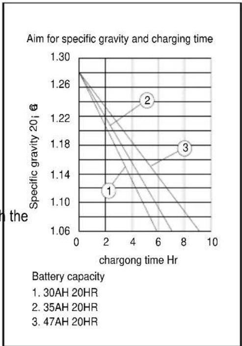
● Measure the specific gravity for the battery fluid by using the hydrometer, and calculate the charging time in according with table shown on right side.
● The specific gravity for the fully charged battery shall be within 1.26 to 1.28. It is recommended to confirm every an hour.
line
| Battery capacity | Chargong time Hr | Specific gravity 20i, g | | ---------------- | ---------------- | ------------------------ | | 1 | 2 | 1.10 | | 2 | 5 | 1.26 | | 3 | 8 | 1.18 |(b) Connect between the DC output socket and the battery terminals using the charging leads. The leads shall be connected making sure of the (+) and (-) polarity.
(c) The DC circuit protector is to be set to ON after confirming the connection, if the protector is in OFF position.

natural_image
Line drawing of a portable gas generator with wheels and control panel (no text or symbols)CAUTION:
- Be sure the economy control switch is turned off while charging the battery.
STOPPING THE ENGINE
- Turn off the power switch of the electric apparatus or disconnect any electric devices.
- Turn the engine switch to STOP position.
Click remote switch to the position.
- Tum the fuel cock lever to OFF.
CAUTION:
- Place the engine switch in the STOP position if the generator set is not used for a long time.
If it is placed in the RUN position, the remote control module is in the state of receiving signal, which will consume the battery and the battery needs to be charged regularly.


natural_image
Line drawing of a mobile phone casing with a black arrow pointing to the top-left panel (no text or symbols)
PERIODIC MAINTENANCE
MAINTENANCE CHART
| Item | Remarks | Pre-operation check (daily) | Initial 1 months or 20 Hr | Every 3 months or 50Hr | Every 6 months or 100Hr | Every 12 months or 300Hr |
| Spark Plug | Check condition adjust gap an clean. Replace if necessary. | ● | ||||
| Engine Oil | Check oil level | ● | ||||
| Replace | ● | ● | ||||
| Air Filter | Clean. Replace if necessary. | ● | ||||
| Fuel Filter | Clean fuel cock filter. Replace necessary | ● | ||||
| Choke | Check choke operation | ● | ||||
| Valve Clearance | Check and adjust when engir is cold. | ● | ||||
| Fuel Line | Check fuel hose for crack o damage. Replace if necessary | ● | ||||
| Exhaust System | Check for leakage. Retighten c replace gasket if necessary | ● | ||||
| Check muffler screen. Clean / replace if necessary. | ● | |||||
| Carburetoi | Check choke operation | ● | ||||
| Cooling system | Check fan damage. | ● | ||||
| Starting system | Check recoil starter operation. | ● | ||||
| Idle speed | Check and adjust engine idle spee | ● | ||||
| Fittings / Fasteners | Check all fittings and fasten correct if necessary. | ● | ||||
| Crankcase breather | Check breather hose for cracks damage. Replace if necessary | ● | ||||
| Generator | Check the pilot light comes on | ● |
Regular maintenance is most important for the best performance and safe operation.
ENGINE OIL REPLACEMENT
- Place the machine on a level surface and warm up the engine for several minutes. Then stop the engine and turn the fuel cock to OFF. Turn the fuel tank cap air vent knob clockwise.
- Loosen the screw and remove the cover.
- Remove the oil filler cap
- Place an oil pan under the engine. Tilt the generator to drain the oil completely
- Replace the generator on a level surface.
- Add engine oil to the upper level.
- Install the oil filler cap
- Install the cover and tighten the screw
● Recommended engine oil: 1.1 L.
API Service SJ
CAUTION:
● Be sure no foreign material enters the crankcase.
- Do not tilt the generator when adding engine oil. This could result in overfilling and damage to the engine
● Clean the oil filter every other 100hr.

AIR FILTER
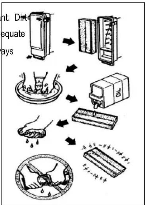
Maintaining an air cleaner in proper condition is very important. Dir induced through improperly installed, improperly serviced, or inadequate elements damages and wears out engines. Keep the element always clean.
- Remove the cover.
- Remove the air filter cover and element.
- Wash the element in solvent and dry.
- Oil the element and squeeze out excess oil. The element should be wet but not dripping.
- Insert the element into the air filter.
- Install the cover
flowchart
graph TD
    A["Uncooked Oven"] --> B["Refrigerator"]
    B --> C["Brush with liquid"]
    C --> D["Brush with water"]
    D --> E["Processed Box"]
    E --> F["Processed Board with granular contents"]
CAUTION:
The engine should never run without the element; excessive and/or cylinder wear may result.
CLEANING AND ADJUSTING SPARK PLUG
- Remove the cover.
- Check for discoloration and remove the carbon.
- Check the spark plug type and gap.
- Install the spark plug.
- Install the cover
Standard electrode color: Tan Color
Standard Spark Plug: F6RTC (TOUCH)
Spark Plug Gap: 0.6-0.7 mm (0.024-0.028 in)
FUEL TANK FILTER
- Remove the fuel tank cap and filter.
- Clean the filter with solvent. If damaged, replace.
- Wipe the filter and insert it.
! WARNING
● Be sure the tank cap is tightened securely.
MUFFLER SCREEN
! WARNING
-
The engine and muffler will be very hot after the engine has been run.
● Avoid touching the engine and muffler while they are still hot with any part of your body or clothing during inspection or repair. -
Remove the cover.
- Remove the muffler screen.


natural_image
Line drawing of a portable gas generator with wheels and control panel (no text or symbols)- Use the flathead screw driver to pry the spark arrester out from the muffler
- Remove the carbon deposits on the muffler screen and spark arrester using a wire brush.
- Install the muffler screen.
- Install the cover
TROUBLE SHOOTING
Engine won't start
1. Fuel systems
No fuel supplied to combustion chamber.
● No fuel in tank....Supply fuel.
● Fuel in tank....Fuel tank cap air vent knob to ON, fuel cock knob to ON.
● Clogged fuel line....Clean fuel line.
- dogged carburetor....Clean carburetor.
2. Engine oil system
Insufficient
● Oil level is low....Add engine oil.
3. Electrical systems
Poor spark
● Spark plug dirty with carbon or wet....Remove carbon or wipe spark plug dry.
● Faulty ignition system....Consult dealer.
4. Compression insufficient
● Worn out piston and cylinder....Consult dealer.
Generator won't produce power
Safety device (AC) to OFF ...Stop the engine, then restart.
Safety device (DC) to OFF ...Press to reset the DC protector

STORAGE
Long term storage of your machine will require some preventive procedures to guard against deterioration.
DRAIN THE FUEL
- Remove the fuel tank cap, drain the fuel from the fuel tank
- Remove the cover, drain fuel from the carburetor by loosening the drain screw.
ENGINE
- Remove the spark plug, pour in about one tablespoon of SAE 10W30 or 20W40 motor oil into the spark plug hole and reinstall the spark plug.
- Use the recoil starter to turn the engine over several times (with ignition off).
- pull the recoil starter until you feel compression.
- Stop pulling.
- Clean exterior of the generator and apply a rust inhibitor.
- Store the generator in a dry, well-ventilated place, with the cover place over it.
- The generator must remain in a vertical position.
SPECIFICATION
| MODEL | XYG6500iE | |
| GENERATOR | Type | Inverter Generator |
| AC Voltage | 240V | |
| 50Hz | ||
| Max. Output | 6.6 kW | |
| Rated Output | 6.0 kW | |
| Power Factor | 1.0 | |
| DC Output | 12V / 5.0A 5V/3.1A | |
| ENGINE | Model | XY188F-1 |
| Type | Air-cooled, 4 cycle, OHV, Gasoline Engine | |
| Bore × Stroke mm×mm | 88×64 | |
| Displacement | 389cc | |
| Max. Output | 7.5kW/ 3600rpm | |
| Fuel | Regular Automobile Gasoline | |
| Fuel tank Capacity | 18.5 liters | |
| Rated Continuous Operation | 4h30min (100% Load) | |
| Lubricating oil | SAE 10W30 | |
| Lubricating oil Capacity | 1.1 liter | |
| Starting System | Electric Starter / Remote starter | |
| Ignition system | C.D.I. | |
| Spark Plug: Type | F6RTC | |
| DIMENSION | Net dimension L×W×H | 750×537×630 |
| Overall dimension L×W×H | 800×590×670 | |
| Net Weight | 89 kg | |
| Dry Weight | 101 kg | |
- Specifications subject to change without prior notice.
WIRING DIAGRAM
240V

flowchart
graph TD
    subgraph GENERATOR_BLOCK
        A["DC WINDING"] --> B["DC5V OUTPUT"]
        C["DC WINDING"] --> D["DC 12V OUTPUT"]
        E["MAIN WINDING"] --> F["INVERTER UNIT"]
        G["SUB WINDING"] --> H["OUTPER RESET"]
        I["IGNITION WINDING"] --> J["ECON. SWITCH"]
    end

    subgraph CONTROL_PANEL_BLOCK
        K["FUSE 15A"] --> L["PROTECTOR 15A"]
        M["FUSE 15A"] --> N["PROTECTOR 15A"]
        O["FUSE 15A"] --> P["PROTECTOR 15A"]
        Q["FUSE 15A"] --> R["PROTECTOR 15A"]
        S["FUSE 15A"] --> T["PROTECTOR 15A"]
        U["FUSE 15A"] --> V["PROTECTOR 15A"]
        W["FUSE 15A"] --> X["PROTECTOR 15A"]
        Y["FUSE 15A"] --> Z["PROTECTOR 15A"]
        AA["FUSE 15A"] --> AB["PROTECTOR 15A"]
        AC["FUSE 15A"] --> AD["PROTECTOR 15A"]
        AE["FUSE 15A"] --> AF["PROTECTOR 15A"]
        AG["FUSE 15A"] --> AH["PROTECTOR 15A"]
        AI["FUSE 15A"] --> AJ["PROTECTOR 15A"]
        AK["FUSE 15A"] --> AL["PROTECTOR 15A"]
        AM["FUSE 15A"] --> AN["PROTECTOR 15A"]
        AO["FUSE 15A"] --> AP["PROTECTOR 15A"]
        AQ["FUSE 15A"] --> AR["PROTECTOR 15A"]
        AS["FUSE 15A"] --> AT["PROTECTOR 15A"]
        AU["FUSE 15A"] --> AV["PROTECTOR 15A"]
        AW["FUSE 15A"] --> AX["PROTECTOR 15A"]
        AY["FUSE 15A"] --> AZ["PROTECTOR 15A"]
        BA["FUSE 15A"] --> BB["PROTECTOR 15A"]
        BC["FUSE 15A"] --> BD["PROTECTOR 15A"]
        BE["FUSE 15A"] --> BF["PROTECTOR 15A"]
        BG["FUSE 15A"] --> BH["PROTECTOR 15A"]
        BI["FUSE 15A"] --> BJ["PROTECTOR 15A"]
        BK["FUSE 15A"] --> BL["PROTECTOR 15A"]
        BM["FUSE 15A"] --> BN["PROTECTOR 15A"]
        BO["FUSE 15A"] --> BP["PROTECTOR 15A"]
        BQ["FUSE 15A"] --> BR["PROTECTOR 15A"]
        BS["FUSE 15A"] --> BT["PROTECTOR 15A"]
        BU["FUSE 15A"] --> BV["PROTECTOR 15A"]
        BW["FUSE 15A"] --> BX["PROTECTOR 15A"]
        BY["FUSE 15A"] --> BZ["PROTECTOR 15A"]
        CA["FUSE 15A"] --> CB["PROTECTOR 15A"]
        CC["FUSE 15A"] --> CD["PROTECTOR 15A"]
        DE["FUSE 15A"] --> DF["PROTECTOR 15A"]
        DG["FUSE 15A"] --> DH["PROTECTOR 15A"]
        DI["FUSE 15A"] --> DJ["PROTECTOR 15A"]
        DK["FUSE 15A"] --> DL["PROTECTOR 15A"]
        DV["FUSE 15A"] --> DW["PROTECTOR 15A"]
        DX["FUSE 15A"] --> DXB["PROTECTOR 15A"]
        DBF["FUSE 15A"] --> DBW["PROTECTOR 15A"]
        DCG["FUSE 15A"] --> DCW["PROTECTOR 15A"]
        DZ["GOLD CAPSICUM"] --> DZB["GOLD CAPSICUM"]
    end

    subgraph ENGINE_BLOCK
        E["SPRING WINDING"] --> E
        F["OIL SENSOR"] --> F
        G["SPARK PLUG"] --> G
        H["IGNITION COIL"] --> H
        I["R/BATTERY"] --> I
        J["Y/G/BLENTATION"] --> J
        K["BATERTY/START MOTOR"] --> K
        L["ELECTRIC MAGNET/ELLE VALVE"] --> L
    end

    subgraph ENGINE_BLOCK
        M["MONITOR ASSY."] --> M
    end

    subgraph CONTROL_PANEL_BLOCK
        N["W/O BL"] --> N
    end

    subgraph CONTROL_PANEL_BLOCK
        O["P/W BL"] --> O
    end

    subgraph CONTROL_PANEL_BLOCK
        P["P/W BL"] --> P
    end

    subgraph CONTROL_PANEL_BLOCK
        Q["P/W BL"] --> Q
    end

    subgraph CONTROL_PANEL_BLOCK
        R["P/W BL"] --> R
    end

    subgraph CONTROL_PANEL_BLOCK
        S["P/W BL"] --> S
    end

    subgraph CONTROL_PANEL_BLOCK
        T["P/W BL"] --> T
    end

    subgraph CONTROL_PANEL_BLOCK
        U["P/W BL"] --> U
    end

    subgraph CONTROL_PANEL_BLOCK
        V["P/W BL"] --> V
    end

    subgraph CONTROL_PANEL_BLOCK
        W["P/W BL"] --> W
    end

    subgraph CONTROL_PANEL_BLOCK
        X["P/W BL"] --> X
    end

    subgraph CONTROL_PANEL_BLOCK
        Y["P/W BL"] --> Y
    end

    subgraph CONTROL_PANEL_BLOCK
        Z["P/W BL"] --> Z
    end

    subgraph CONTROL_PANEL_BLOCK
        AA["P/W BL"] --> AA
    end

    subgraph CONTROL_PANEL_BLOCK
        AB["P/W BL"] --> AB
    end

    subgraph CONTROL_PANEL_BLOCK
        AC["P/W BL"] --> AC
    end

    subgraph CONTROL_PANEL_BLOCK
        AD["P/W BL"] --> AD
    end

    subgraph CONTROL_PANEL_BLOCK
        AE["P/W BL"] --> AE
    end

    subgraph CONTROL_PANEL_BLOCK
        AF["P/W BL"] --> AF
    end

    subgraph CONTROL_PANEL_BLOCK
        AG["P/W BL"] --> AG
    end

    subgraph CONTROL_PANEL_BLOCK
        AH["P/W BL"] --> AH
    end

    subgraph CONTROL_PANEL_BLOCK
        AI["P/W BL"] --> AI
    end

    subgraph CONTROL_PANEL_BLOCK
        AJ["P/W BL"] --> AJ
    end

    subgraph CONTROL_PANEL_BLOCK
        AK["P/W BL"] --> AK
    end

    subgraph CONTROL_PANEL_BLOCK
        AL["P/W BL"] --> AL
    end

    subgraph CONTROL_PANEL_BLOCK
        AM["P/W BL"] --> AM
    end

    subgraph CONTROL_PANEL_BLOCK
        AN["P/W BL"] --> AN
    end

    subgraph CONTROL_PANEL_BLOCK
        AO["P/W BL"] --> AO
    end

    subgraph CONTROL_PANEL_BLOCK
        AP["P/W BL"] --> AP
    end

    subgraph CONTROL_PANEL_BLOCK
        AQ["P/W BL"] --> AQ
    end

    subgraph CONTROL_PANEL_BLOCK
        AR["P/W BL"] --> AR
    end

    subgraph CONTROL_PANEL_BLOCK
        AS["P/W BL"] --> AS
    end

    subgraph CONTROL_PANEL_BLOCK
        AT["P/W BL"] --> AT
    end

    subgraph CONTROL_PANEL_BLOCK
        AU["P/W BL"] --> AU
    end

    subgraph CONTROL_PANEL_BLOCK
        AV["P/W BL"] --> AV
    end

    subgraph CONTROL_PANEL_BLOCK
        AW["P/W BL"] --> AW
    end

    subgraph CONTROL_PANEL_BLOCK
        AX["P/W BL"] --> AX
    end

    subgraph CONTROL_PANEL_BLOCK
        AY["P/W BL"] --> AY
    end

    subgraph CONTROL_PANEL_BLOCK
        AZ["P/W BL"] --> AZ
    end

    subgraph CONTROL_PANEL_BLOCK
        BA["P/W BL"] --> BA
    end

    subgraph CONTROL_PANEL_BLOCK
        BB["P/W BL"] --> BB
    end

    subgraph CONTROL_PANEL_BLOCK
        BC["P/W BL"] --> BC
    end

    subgraph CONTROL_PANEL_BLOCK
        BD["P/W BL"] --> BD
    end

    subgraph CONTROL_PANEL_BLOCK
        BE["P/W BL"] --> BE
    end

    subgraph CONTROL_PANEL_BLOCK
        BF["P/W BL"] --> BF
    end

    subgraph CONTROL_PANEL_BLOCK
        BG["P/W BL"] --> BG
    end

    subgraph CONTROL_PANEL_BLOCK
        BH["P/W BL"] --> BH
    end

    subgraph CONTROL_PANEL_BLOCK
        BI["P/W BL"] --> BI
    end

    subgraph CONTROL_PANEL_BLOCK
        BJ["P/W BL"] --> BJ
    end

    subgraph CONTROL_PANEL_BLOCK
        BK["P/W BL"] --> BK
    end

    subgraph CONTROL_PANEL_BLOCK
        BL["P/W BL"] --> BL
    end

- GASOLINE INVERTER GENERATOR USER'S MANUAL
- INTRODUCTION
- CONTENTS
- FUEL IS HIGHLY FLAMMABLE AND POISONOUS
- ENGINE AND MUFFLER MAY BE HOT
- ELECTRIC SHOCK PREVENTION
- NOTE:
- CONNECTION NOTES
- CONTROL FUNCTION
- OIL WARNING SYSTEM
- ENGINE SWITCH
- ECONOMY CONTROL SWITCH
- DC CIRCUIT PROTECTOR
- CAUTION:
- OUTPUT RESET
- REMOTE CONTROL SWITCH
- BRAKE LEVER
- FUEL COCK
- DATA DISPLAY INSTRUMENT
- PRE-OPERATION CHECK
- CHECK ENGINE FUEL
- WARNING:
- CHECK ENGINE OIL
- GROUND (Earth)
- CONNET BATTERY
- OPERATION
- STARTING THE ENGINE
- A Electric start
- B Remote start
- USING ELECTRIC POWER
- AC APPLICATION
- OVERLOAD INDICATOR LIGHT
- DC APPLICATION (option)
- STOPPING THE ENGINE
- PERIODIC MAINTENANCE
- ENGINE OIL REPLACEMENT
- AIR FILTER
- CLEANING AND ADJUSTING SPARK PLUG
- FUEL TANK FILTER
- ! WARNING
- MUFFLER SCREEN
- TROUBLE SHOOTING
- Engine won't start
- Fuel systems
- Engine oil system
- Electrical systems
- Compression insufficient
- Generator won't produce power
- STORAGE
- DRAIN THE FUEL
- ENGINE
- WIRING DIAGRAM
Brand : Gentrax
Model : GS-6500IE
Category : Generator