Inverter 2.0kW - Generator Gentrax - Free user manual and instructions
Find the device manual for free Inverter 2.0kW Gentrax in PDF.


| Product Type | Inverter Generator |
| Brand | Gentrax |
| Model | Inverter 2.0kW |
| AC Output Voltage | 240V (50Hz/60Hz) |
| Maximum AC Output | 2000W |
| Rated AC Output | 1700W |
| DC Output | 12V / 5.0A |
| Engine Type | Air-cooled, 4-cycle, OHV, Gasoline |
| Displacement | 100 cc |
| Max. Engine Output | 2.0 kW / 5500 rpm |
| Fuel | Regular unleaded gasoline |
| Fuel Tank Capacity | 4.5 liters |
| Continuous Operation (50% load) | 9 hours |
| Starting System | Recoil starter |
| Ignition System | T.C.I |
| Oil Capacity | 0.75 liter (SAE 10W30) |
| Dimensions (L x W x H) | 525 x 282 x 458 mm |
| Net Weight | 18.5 kg |
| Gross Weight | 19.5 kg |
| Safety Features | Oil Alert, Overload protection, Low oil shutdown |
| Eco Mode | Economy control switch for fuel saving |
Frequently Asked Questions - Inverter 2.0kW Gentrax
User questions about Inverter 2.0kW Gentrax
0 question about this device. Answer the ones you know or ask your own.
Ask a new question about this device
Download the instructions for your Generator in PDF format for free! Find your manual Inverter 2.0kW - Gentrax and take your electronic device back in hand. On this page are published all the documents necessary for the use of your device. Inverter 2.0kW by Gentrax.
USER MANUAL Inverter 2.0kW Gentrax

INVERTER GENERATOR
User Manual


This product is approved with RCM (Regulatory Compliance Mark)

Under new ACMA labelling arrangements introduced from 1 March 2013, the ACMA is transitioning its regulatory arrangements toward the use of the RCM as the single compliance mark used to indicate an item's compliance with applicable ACMA regulatory arrangements—that is, for telecommunications, radiocommunications, EMC and EME. An item can only be labelled with the RCM when it complies with all requirements under all relevant arrangements. An item must comply with all ACMA arrangements and where relevant.
A national database has been designated for all supplier registrations. A supplier must register on the database before applying the RCM to any item. The database is also used for registration of suppliers under the Electrical Equipment Safety System (EESS) being introduced by some state and territory governments.
- The three existing compliance marks (C-Tick, A-Tick and RCM) are being consolidated into a single compliance mark—the RCM.
- The RCM indicates a device's compliance with applicable ACMA technical standards—that is, for telecommunications, radiocommunications, EMC and EME.
• A national database has been designated for all supplier registration. - A supplier will not be required to include supplier identification on devices labelled with the RCM.
- The ACMA's four labelling notices reflect the new labelling arrangements.
CONTENT
Certificate of Guarantee 2
Guarantee Registration Form 2
Important Safety Precaution....3
Specific Safety Instructions....3
Fuel Filling Instructions....3
General Safety Rules....3
Components & Control 4
Pre-operation Check ....5
Earthing the generator ....5
Location 5
Engine Oil 5
Fuel....5
Checking Air Filter 5
Starting the generator 6
Operations....7
Break In Period....7
DC Battery Charging Function 7
Stopping the engine 8
Maintenance....8
Maintenance chart 8
Spark Plug 9
Engine Oil Replacement 9
Fuel Tank Filter.... 10
Air Filter 10
Muffler Screen and Spark Arrestor 11
Drain the Fuel 11
Engine 11
Specifications 12
Troubleshooting 13
CERTIFICATE OF GUARANTEE
This product is guaranteed as per listed in the sales contract between the retailer and original purchaser. This guarantee only applies to defects arising from, defective materials and or faulty workmanship that become evident during the guarantee period only and does not include consumable items. The manufacturer will provide parts needed for repairing the machine subject to the following:
√ That the product has been used in accordance with the guidelines as detailed in the product manual and that it has not been subjected to misuse, abuse or used for a purpose for which it was not intended.
√ That has not been used for hire purposes.
√ Copy of proof of purchase and Guarantee Registration Form must be supplied at the time of lodging a claim.
Transit damage is excluded from this guarantee, for such damage the transport company is responsible. Claims made under this guarantee must be made in the first instance, directly to the retailer within the guarantee period. Only under exceptional circumstances should the product be returned to the manufacturer. In this case it shall
be the consumer's responsibility to return the product at their cost ensuring that the product is adequately packed to prevent transit damage and must be accompanied with a brief description of the fault and a copy of the receipt or other proof of purchase. The manufacturer and retailer shall not be liable for any special, exemplary, direct, indirect, incidental, or consequential loss or damage under this guarantee.
GUARANTEE
REGISTRATION FORM
Full Name: ____
Delivery Address: ____
Email Address:
Phone number: ____
Original Date of Purchase: ____
Purchase site/Retailers name: ____
NOTE: Manual with fully filled registration form and a proof of purchase showing date of purchase has to be presented when lodging a warranty claim.

IMPORTANT SAFETY PRECAUTION
SPECIFIC SAFETY INSTRUCTIONS
√ Petrol or diesel powered generators must never be used in an unventilated closed spaces. The exhaust fumes are highly dangerous and can cause "Carbon Monoxide Poisoning" which will cause drowsiness and death. The generator must be mounted on a firm level surface. The electrical output load must not exceed the maximum load of the generator. (check specification) Exceeding the rated load will damage the unit or shorten its life and will invalidate the guarantee.
√ The engine must not be run at speeds that exceed the maximum stated on the rating plate.
√ Operating an engine at excessive speeds increases the hazard of personal injury.
√ Mains extension leads, mains supply leads, and all electrical equipment must be in good working condition.
√ Never operate electrical equipment with damaged or defective mains supply leads.
√ Keep the area around the generator clear of obstructions at all times. Never locate the generator against a building or near a canvas or plastic structure i.e. Tents etc.
√ Always use the correct fuel mix as stated in the user manual.
√ To prevent fire, always stop the engine when refueling and never over fill the fuel tank.
√ Always clean up spilt fuel immediately using sand.
√ Do not use the generator in or near an explosive atmosphere.
√ To prevent an electric shock, never operate the machine in rain, snow or touch with wet hands.
√ Check the fuel system periodically for leaks, seals and hoses should be checked for signs of deterioration or chafing. Check for loose or missing clamps, damaged fuel tank or filler cap. All defects should be corrected before further use. Always allow the generator to reach full operating speed before connecting any electrical load.
√ Always disconnect the electrical load before switching the generator off. To prevent surging that may possibly damage electrical equipment, do not allow engine to run out of fuel while electrical loads are connected.
√ Before transporting the generator in a vehicle, drain all fuel to prevent leakage. To prevent an electric shock and fire, never connect an electrical load with the electrical output switched
on. Do not connect the generator to any other electrical source.
√ The engine speed has been factory set to provide safe operation. Tampering with the engine speed adjustment could result in overheating of attachments and could cause a fire. Never attempt to "speed-up" the engine to obtain more performance. Both the output voltage and frequency will be thrown out of standard by this practice, endangering attachments and the user. Store the generator in a well-ventilated area with the fuel tank empty.
FUEL FILLING INSTRUCTIONS
WARNING! Select bare ground for fuelling and move at least 10 feet (3m) from fuelling spot before starting the engine. After refuelling, properly tighten fuel cap; wipe off any spilled fuel and check for leakage.
WARNING! If fuel gets spilled on clothes, especially trousers, it is very important to change clothes immediately. Do not rely on evaporation. Flammable quantities of fuel may remain on clothes after a spill for longer than expected.
WARNING! Vibrations can cause an improperly tightened fuel cap to loosen or come off and spill quantities of fuel. In order to reduce the risk of fuel spillage and fire, tighten fuel filler cap by hand as securely as possible. Before use always make sure that the fuel cap has been properly tightened. Check for fuel leakage while refuelling and during operation. If a fuel leak is suspected, do not start or run the engine until leak is fixed and spilled fuel has been wiped away.
WARNING! The ignition system of your unit produces an electromagnetic field of a very low intensity. This field may interfere with some pacemakers. To reduce the risk of serious or fatal injury, people with a pacemaker fitted should consult their physician and the pacemaker manufacturer before operating this tool.
GENERAL SAFETY RULES
WARNING! Read all instructions Failure to follow all instructions listed below may result in electric shock, fire and/or serious injury. The term "power tool" in all of the warnings listed below refers to your mains operated (corded) power tool or battery operated (cordless) power tool.





COMPONENTS & CONTROL
① Economy control switch
② Engine switch
3 Fuel tank
4 Spark plug
5 Muffler
6 Carrying handle
7 Choke lever
8 AC pilot light
9 Overload indicator light
10 Oil warning light
11 DC protector
12 Ground (earth) terminal
13 DC receptacle
14 AC receptacle
15 Frequency transfer switch
16 Fuel tank cap
17 Fuel filter
18 Fuel pump
19 Recoil starter
20 Fuel cock
21 Oil filler cap
22 Air filter cover
1

12
The image is too blurry to recognize any text content.
9
01



PRE-OPERATION CHECK
EARTHING THE GENERATOR

It is recommended that you earth the generator. Use an earth lead of sufficient current capacity:
Diameter: 0.12mm (0.005in)/ampere Ex:10 Ampere-1.2mm (0.055in)
NOTE: The wire and earth stake are not supplied with the unit.
LOCATION
Place the generator on firm level ground away from buildings or other structures and ensure the exhaust is not obstructed.
Never operate generator in a wet(rain) or snow condition.
ENGINE OIL
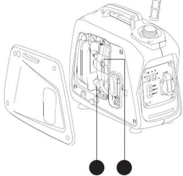
The Oil Alert system is designed to prevent engine damage caused by an insufficient amount of oil in the crankcase. Before the oil level in the crankcase can fall below a safe limit, the Oil Alert system will automatically shut down the engine (the engine switch will remain in the ON position).
Check the oil level BEFORE EACH USE with the generator on a level surface with the engine stopped.
-
Loosen the cover screws and remove the maintenance cover.
-
Remove the oil filler cap and wipe the dipstick clean if fitted.
-
Check the oil level by inserting the dipstick into the filler neck without screwing it in.
- If the level is low, fill to the top of the oil filler neck with the recommended oil.
Use high-detergent, premium quality 4-stroke engine SAW 10W-30
WARNING! Non-detergent and 2-stroke engine oils will damage the engine and are not recommended.

FUEL
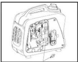
Before attempting to start the generator, ensure at least 2L of fuel is added into the tank. If not enough fuel, refill with unleaded petrol. For fuel tank capacity, please check specification page.

√ Do not refill tank while engine is running and hot
√ Close fuel cock while refuelling. Be careful and always use fuel filter when refuelling to prevent dust, dirt, water or other foreign objects into fuel tank.
√ Do not fill over the top of the fuel filter.
√ Wipe off spilt fuel thoroughly before starting engine.
√ Keep open flames away
CHECKING AIR FILTER
- Unscrew and remove the Air Filter cover. Take out the Air Filter foam element and inspect for cleanliness.
- Clean the Air Filter element with a non-flammable solvent. Squeeze dry and soak in clean engine oil.
- Squeeze out excess oil and reinstall. Replace the element if it is torn or damaged.


STARTING THE GENERATOR
Before using this generator it must be prepared correctly before use. Locate the generator on firm level ground away from buildings or other structures ensuring that the exhaust is not obstructed.
Before starting the engine make sure that all the electrical loads are disconnected from the generator AC outlet socket.
√ Open the fuel filler cap vent and the fuel cock


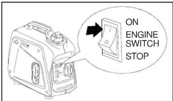
√ Turn the engine switch to the On position and the economy switch to the Off position
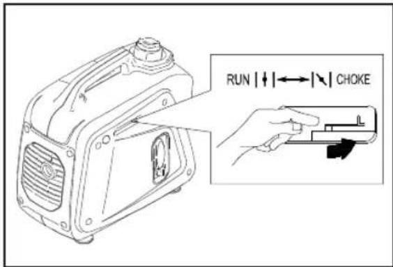
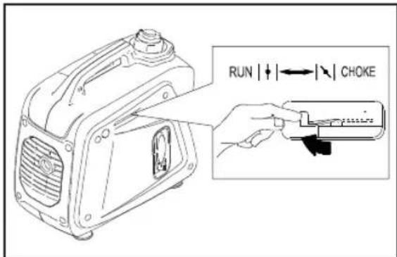
√ Set the choke to the "CHOKE" position. If engine is hot, generator may be started with choke position being on "RUN"
√ Hold down the generator firmly with one hand. With the other hand grip the recoil starter cord handle and pull slowly until resistance is felt indicating that the recoil starter is engaged. When resistance is felt pull the cord sharply. Continue this procedure until the engine starts.

√ Once started, turn the choke switch to "RUN"


OPERATIONS
WARNING! Before connecting any electrical load to the generator ensure that the load does not exceed the maximum as stated in the manual. Ensure that the appliance being connected is in good working order and that the mains supply lead is long enough to reach the generator without any strain.
WARNING! DC power and AC power can be used at the same time but DO NOT exceed the maximum power output, as shown on the manual.
Under normal working conditions the (Green) output indicator light will be illuminated.

If the generator is overloaded or if there is a malfunction or a short circuit in a connected appliance, the (Green) output indicator will extinguish and the (Red) overload indicator light illuminates and the power to the connected appliance will be disconnected.
When an electric motor is started, both the (Red) overload indicator and the (Green) output indicator will illuminate simultaneously. This is normal, the (Red) over- load indicator extinguishes after about four (4) seconds. If the (Red) overload indicator remains illuminated, consult your generator dealer.
▲NOTE
For equipment with an inductive load (more power will be required at initial start). Under these conditions it is normal for both the (Red) overload indicator and the (Green) output indicator will illuminate simultaneously for a short period about four (4) seconds. After the appliance starts, the (Red) over-load indicator extinguishes and the (Green) output indicator will remain illuminated.
BREAK IN PERIOD
a. Breaking-in the Engine will help to ensure proper equipment and Engine operation.
b. The break-in period will last about 25 hours of use.
DO NOT exceed 75% of the Generator's rated capacity during this period.
Change the Engine oil after this period. Under normal operating conditions subsequent maintenance follows the schedule explained in the MAINTENANCE section.
DC BATTERY CHARGING FUNCTION
This function is applicable to 12v battery charging only.
Disconnect the leads from the battery, Loosen the vents on the battery. Ensure the battery fluid level is correct.
Using a hydrometer (not supplied) measure the specific gravity of the battery fluid and calculate the charging time accordance with table shown.
Attach the 12v charging leads to the battery observing the correct polarity (Red = + Positive) (Black = - Negative) Plug the 12v charger lead into the socket on the generator. The specific gravity for the fully charged battery shall be within 1.26 to 1.28. Check the gravity every hour.
Aim for specific gravity and charging time


STOPPING THE ENGINE
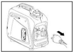
- Turn off and disconnect all electrical appliances.
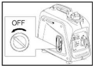
- Turn the fuel cock to "OFF" position
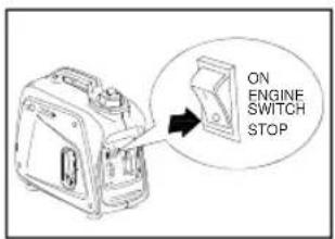
- Push the engine switch to "STOP"

- Turn the fuel tank cap air vent to "CLOSED" position
MAINTENANCE
MAINTENANCE CHART
Regular maintenance is most important for the best performance and safe operation.
| ItemRemarks | Pre-operation check (daily) | Initial 1 month or 20Hr | Every 3 months or 50Hr | Every 6 months or 100Hr | Every 12 month or 300Hr | |
| Spark Plug | Check condition adjust gap and clean. Replace if necessary. | √ | ||||
| Engine Oil | Check oil level | √ | ||||
| Replace | √ | √ | ||||
| Oil filter | Clean oil filter | √ | ||||
| Air Filter | Clean. Replace if necessary. | √ | ||||
| Fuel Filter | Clean fuel cock filter. Replace if necessary | √ | ||||
| Choke | Check choke operation | √ | ||||
| Valve Clearance | Check and adjust when engine is cold. | √ | ||||
| Fuel Line | Check fuel hose for crack or damage. Replace if necessary. | √ | ||||
| Exhaust System | Check for leakage. Retighten or replace gasket if necessary Check muffler screen. Clean / replace if necessary. | √ | √ | |||
| Carburetor | Check choke operation | √ | ||||
| Cooling system | Check fan damage. | √ | ||||
| Starting system | Check recoil starter operation. | √ | ||||
| Idle speed | Check and adjust engine idle speed | √ | ||||
| Fittings / Fasteners | Check all fittings and fasteners correct if necessary. | √ | ||||
| Crankcase breather | Check breather hose for cracks or damage. Replace if necessary | √ | ||||
| Generator | Check if the pilot light comes on | √ | ||||



8
NVERTER GENERATOR: User Manual




SPARK PLUG
To ensure proper engine operation, the spark plug must be properly gapped and free of deposits.
Steps:
- Remove spark plug maintenance cover.

- Pull the HT lead off the spark plug and clean any dirt from around the spark plug base. Using the wrench supplied remove the spark plug.
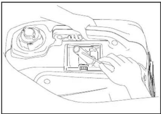

- Visually inspect the spark plug. Discard it if the insulator is cracked or chipped. Please use a spark plug gauge to check the spark plug gap, it should be 0.6-0.7mm (0.024-0.028inch).
- Check that the spark plug sealing washer is in good condition, and thread the spark plug in by hand to prevent cross threading. After the spark plug is seated, tighten with a spark plug wrench to compress the washer. If installing a new spark plug, tighten 1/2 turn after the spark plug seats to compress the washer. If reinstalling a used spark plug, tighten 1/8 – 1/4 turn after the spark plug seats to compress the washer.
- Reinstall the spark plug cap on the spark plug securely.
- Reinstall the spark plug maintenance cover.
WARNING! Spark plug must be assembled firmly, or it will become hot and may damage generator. A loose spark plug can overheat and damage the engine.
ENGINE OIL REPLACEMENT
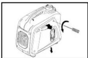

- Place the generator on a level surface and warm up the engine for several minutes. Then stop the engine and turn the fuel tap to "OFF".
- Close the fuel tank cap air vent.
- Loosen the four screw and remove the side cover.
-
Remove the oil filler dipstick.
-
Place an oil pan under the engine. Tilt the generator to drain the oil completely.
- Place the generator on a level surface.
- Add engine oil to the upper level. Use SAE10W30 or 15W40 grade oil.
- Install the oil filler dipstick securely.
- Re-fit the side cover and tighten the screws.


FUEL TANK FILTER
After every 100 hours of running or every 6 months the fuel tank filter should be removed and cleaned.
Remove the fuel tank filler cap and the filter, clean the filter thoroughly using an environmentally friendly water based degreasing agent and re-fit.

AIR FILTER
A dirty air cleaner will restrict air flow to the carburettor. To prevent carburettor malfunction, service the air cleaner regularly.
Warning! Using gasoline or flammable solvent to clean the air filter can cause a fire or
explosion. Use only soapy water or a non-flammable solvent.
√ Having first removed the side maintenance cover, loose the 2 nuts (with M10 socket wrench) and 6 screws on the air cleaner cover, and remove the cover. Then release 1 bolt (with M8 socket wrench).
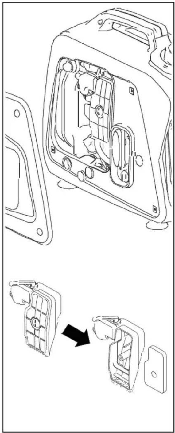




√ Pull away the air cleaner housing, use the flat screwdriver to release two plastic clips, then the filter can now be removed.
![graph TD A["Water washing"] --> B["Hand washing cup"] B --> C["Hand washing cup with liquid"] C --> D["Hand washing cup with liquid"] D --> E["Hand washing cup with liquid"] E --> F["Hand washing cup with liquid"] F --> G["Hand washing cup with liquid"] G --> H["Hand washing cup with liquid"] H -->…](/content/2026/05/897243/images/854a46cd5cec12982b17955e24c7213c144fbbafaba295ae359293a2fac48add.jpg)
√ Wash the air filter in a solution of household detergent and warm water, then rinse it thoroughly, or wash it in a non flammable or high flash point solvent.
√ Allow the air filter to dry thoroughly.
MUFFLER SCREEN AND SPARK ARRESTOR
- Remove the screen cover
- Remove the muffler screen


- Use the flathead screw driver to pry the spark arrester out from the muffler
- Remove the carbon deposits on the muffler screen and spark arrester using a wire brush
- Install the muffler screen
- Install the cover
Long term storage of your generator will require some preventive procedures to guard against deterioration.
DRAIN THE FUEL
- Remove the fuel tank cap, drain the fuel from the fuel tank.
- Remove the cover, drain fuel from the carburetor by loosening the drain screw.
ENGINE
- Remove the spark plug, pour in about 15ml of SAE 10W30 or 15W40 motor oil into the spark plug hole and reinstall the spark plug.
- Use the recoil starter to turn the engine over several times (with engine switch off).
- Pull the recoil starter until you feel compression, then stop.
- Clean exterior of the generator and apply a rust inhibitor.
- Store the generator in a dry, well-ventilated area. Cover the generator.


SPECIFICATIONS
| MODEL 800W 1200W 2000W | |||||
| GENERATOR | Type Inverter Generator | ||||
| AC Voltage | 50Hz 240V | ||||
| 60Hz 240V | |||||
| Max. Output | 800W | 1200W 2000W | |||
| Rated Output 700W 1000W 1700W | |||||
| DC Output 12V / 4.0A12V / 4.0A 12V / 5.0A | |||||
| ENGINE | Type Air-cooled, 4 cycle, OHV, Gasoline Engine | ||||
| Bore×Stroke mm×mm 39 x 33.5mm 44 x 39.5mm | 52.4 x 46mm | ||||
| Displacement | 40 cc | 60 cc 100 cc | |||
| Max. Output | 1.0KW / 5500rpm | 1.2KW / 5500rpm | 2.0KW / 5500rpm | ||
| Fuel | Regular Automobile Gasoline | ||||
| Fuel tank Capacity | 2.1 liters | 3.0 liters | 4.5 liters | ||
| Rated Continuous Operation (50% load) | 6 hrs | 6.6 hrs | 9 hrs | ||
| Lubricating oil | SAE 10W30 | ||||
| Lubricating oil Capacity | 0.30 liter | 0.35 liter | 0.75 liter | ||
| Starting System | Recoil Starter | ||||
| Ignition system | T.C.I | ||||
| DIMENSION | Overall dimension L×W×H | 395 x 209 x 355 | 448 x 236 x 392 | 525 x 282 x 458 | |
| Net Weight 12.5 Kg | 8.5 Kg 18.5 Kg | ||||
| Gross Weight | 9.5 Kg | 13.5 Kg | 19.5 Kg | ||
Specifications subject to change without prior notice.


TROUBLESHOOTING

![graph TD A["CONDITION"] --> B["Insufficient compression"] A --> C["FUEL SYSTEM PROBLEMS"] A --> D["ELECTRIC SYSTEM PROBLEMS"] B --> E["No oil/ Low oil level"] B --> F["Loose spark plug"] B --> G["Loose cylinder head bolt"] B --> H["Damaged gasket"] B --> I["Fill sump with correct oil"] B --> J["Tigh…](/content/2026/05/897243/images/6885519d201fd95ce1f2b3769d4d45af017049f0a330bf7e29b0ad30ccca9009.jpg)


![graph TD A["INDICATOR LIGHT ON.<br>No AC output"] --> B["Tripped circuit breaker"] A --> C["Poor connection or faulty lead"] A --> D["Broken recepticle"] A --> E["Faulty circuit breaker"] A --> F["Generator problem"] G["INDICATOR LIGHT OFF.<br>No AC output"] --> H["Generator problem"] I["Output powe…](/content/2026/05/897243/images/0437ca5914964c8c2b4f7aa70e8da461224c4c811bfd9ff8335e15572b16d6b8.jpg)




14 NVERTER GENERATOR: User Manual


Back Cover Page.ai 1 9/1/2014 2:47:23 PM


- INVERTER GENERATOR
- THIS PRODUCT IS APPROVED WITH RCM (REGULATORY COMPLIANCE MARK)
- CONTENT
- CERTIFICATE OF GUARANTEE
- GUARANTEE
- REGISTRATION FORM
- IMPORTANT SAFETY PRECAUTION
- SPECIFIC SAFETY INSTRUCTIONS
- FUEL FILLING INSTRUCTIONS
- GENERAL SAFETY RULES
- COMPONENTS & CONTROL
- PRE-OPERATION CHECK
- LOCATION
- ENGINE OIL
- FUEL
- CHECKING AIR FILTER
- STARTING THE GENERATOR
- OPERATIONS
- ▲NOTE
- BREAK IN PERIOD
- DC BATTERY CHARGING FUNCTION
- STOPPING THE ENGINE
- MAINTENANCE
- MAINTENANCE CHART
- SPARK PLUG
- STEPS
- ENGINE OIL REPLACEMENT
- FUEL TANK FILTER
- AIR FILTER
- MUFFLER SCREEN AND SPARK ARRESTOR
- DRAIN THE FUEL
- ENGINE
- SPECIFICATIONS
- TROUBLESHOOTING
Brand : Gentrax
Model : Inverter 2.0kW
Category : Generator