NTC-140W-02 - Router Netcomm - Free user manual and instructions
Find the device manual for free NTC-140W-02 Netcomm in PDF.


| Product Type | 4G LTE WiFi M2M Router |
| Model Number | NTC-140W-02 |
| Dimensions | 143 x 107 x 34 mm |
| Weight | Approx. 235 g |
| Power Input | 8-40 V DC via Molex connector (recommended 12V 1.5A) |
| Cellular Support | LTE Bands 1/3/7/8/20, UMTS/HSPA+/DC-HSPA+ (Bands 1/2/5/6/8), GSM/GPRS/EDGE |
| WiFi | 802.11b/g/n 2x2 MIMO (access point and client modes) |
| Ethernet Ports | 2 x 10/100/1000 Base-T with Auto MDIX |
| SIM Slot | 1 x lockable SIM tray (push-to-release) |
| Antenna Connectors | 2 x SMA (cellular), 1 x SMA (GPS), 2 x RP-SMA (WiFi) |
| GPS | Embedded GPS receiver (1575.42 MHz), supports GLONASS |
| USB Port | Mini USB 2.0 OTG (supports up to 0.5A) |
| Memory | 256 MB Flash (~120 MB available for user storage) |
| Operating Temperature | -30°C to +70°C (Class A), -40°C to +85°C (Class B) |
| Mounting Options | DIN rail, wall (flat or via DIN bracket), pole, desk |
| Wireless Security | WPA2-PSK, MAC address filtering, WPA encryption (AES/TKIP) |
| VPN Support | OpenVPN (client/server), PPTP, L2TP, IPsec |
| Management | Web UI, CLI (Telnet/SSH), TR-069, SNMP, SMS diagnostics |
| LED Indicators | Power, WiFi, Network, Signal Strength (5 level), Ethernet port status |
| I/O Interface | 1 x multipurpose I/O pin (digital/analogue/ignition sense) |
| Regulatory Compliance | CE, FCC, IC, RCM, designed to ISO7637 (vehicle) |
| Warranty | See product warranty on NetComm website |
Frequently Asked Questions - NTC-140W-02 Netcomm
User questions about NTC-140W-02 Netcomm
0 question about this device. Answer the ones you know or ask your own.
Ask a new question about this device
Download the instructions for your Router in PDF format for free! Find your manual NTC-140W-02 - Netcomm and take your electronic device back in hand. On this page are published all the documents necessary for the use of your device. NTC-140W-02 by Netcomm.
USER MANUAL NTC-140W-02 Netcomm
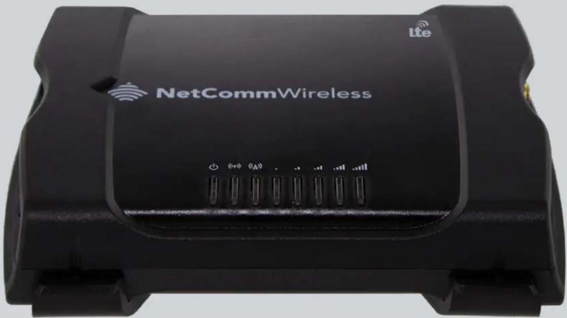
NTC-140W Series – 4G WiFi M2M Router
Copyright
Copyright© 2014 NetComm Wireless Limited. All rights reserved.
The information contained herein is proprietary to NetComm Wireless. No part of this document may be translated, transcribed, reproduced, in any form, or by any means without prior written consent of NetComm Wireless.

Note: This document is subject to change without notice.
Save our environment
When this equipment has reached the end of its useful life, it must be taken to a recycling centre and processed separately from domestic waste.
The cardboard box, the plastic contained in the packaging, and the parts that make up this device can be recycled in accordance with regionally established regulations. Never dispose of this electronic equipment along with domestic waste. You may be subject to penalties or sanctions under the law. Instead, ask for disposal instructions from your municipal government.
Please be responsible and protect our environment.
This manual covers the following products:
NetComm Wireless NTC-140W-02
| DOCUMENT VERSION | DATE |
| 1.0 - Initial document release | 30 July 2014 |
Table 1 - Document Revision History
Table of Contents
Overview 5
Introduction....5
Target audience....5
Prerequisites 5
Notation 5
Product introduction....6
Product overview....6
Product features....6
Package contents....6
Physical dimensions and indicators 7
Physical dimensions 7
LED indicators....8
Ethernet port LED indicators....9
Interfaces 10
Placement of the router....11
Mounting options....11
DIN rail mounting bracket....11
Wall mounted via DIN rail bracket....12
DIN rail mount 12
Pole mount using DIN rail bracket 13
Desk mount....13
Installation and configuration of the NTC-140W Series router....14
Powering the router 14
Installing the router 14
Advanced configuration 15
Status 16
Networking....19
Data Connection....19
Connect on demand....24
SIM Management 27
Operator settings....28
SIM security settings....29
LAN 33
Wireless settings....37
Ethernet LAN/WAN 45
WAN failover....47
Routing 49
VPN 59
Services....72
Dynamic DNS....72
Network time (NTP)....73
Data stream manager 74
PADD....79
SNMP 80
TR-069....82
GPS....84
USSD....87
IO configuration....88
SMS messaging 90
Diagnostics 94
Sending an SMS Diagnostic Command....97
System 106
Log 106
System configuration....109
Administration 113
Watchdogs....121
Power management 124
USB-OTG....127
Storage 128
Reboot....129
Appendix A: Tables....130
Appendix B: Default Settings....131
Restoring factory default settings 132
Appendix C: Recovery mode 133
Accessing recovery mode....133
Status 134
Log 134
Application Installer....135
Settings....135
Reboot 135
Appendix D: HTTPS - Uploading a self-signed certificate....136
Appendix E: RJ-45 connectors 138
Appendix G: Input/Output 139
Overview 139
Appendix H: Obtaining a list of RDB variables....144
Appendix I: Using USB devices and MicroSD cards....145
Accessing USB/SD card storage devices 145
Host and Device mode 145
Technical Data....146
Safety and product care....148
Product Warranty....152
Overview
Introduction
This document provides you all the information you need to set up, configure and use the NetComm Wireless NTC-140W Series router.
Target audience
This document is intended for system integrators or experienced hardware installers who understand telecommunications terminology and concepts.
Prerequisites
Before continuing with the installation of your NTC-140W Series router, please confirm that you have the following:
An electronic computing device with a working Ethernet network adapter and a web browser such as Internet Explorer, Mozilla Firefox or Google Chrome.
Notation
The following symbols are used in this user guide:

The following note requires attention.

The following note provides a warning.

The following note provides useful information.
Product introduction
Product overview
Powerful and flexible industrial cellular router platform supporting LTE with fallback to 3G/UMTS and GSM/GPRS/EDGE (Fallback only applies to certain models)
Ideal for providing primary and backup wireless connectivity over LTE networks
Industrial Features – rugged enclosure, wide operating temperature range, wall mount option and a flexible range of power options
Embedded Linux operating system allowing for the installation of custom applications. Software Development Kit (SDK) is available
Web interface for easy centralized configuration and management from any PC
Two 10/100/1000 Base T ports for Ethernet connection
VPN support for establishing a secure connection over public cellular network using OpenVPN
Supports SNMP with cellular specific MIB, PPPoE, RIP, VRRP. DDNS, MAC /NET address filtering, Open VPN, DHCP/DHCP relay
System monitoring, remote diagnostics and configuration over the air, diagnostic log viewer via browser
802.11n WiFi access point or client with 2x2 MIMO antenna technology
Integrated GPS support
TR-069 device management (optional)
Ignition Sense capability for graceful shutdown and startup in vehicle applications
Configurable power save mode with minimum current draw when not operational
Tested for vehicular applications IEC Class 5M2 and MIL-STD-810F Method 516.5Package contents.
Product features
The robust and intelligent NetComm 4G WiFi M2M Router is designed to provide real-time M2M data connectivity even in harsh environments. The NTC-140W creates reliable point-to-point or point-to-multi-point wide area network (WAN) connections for a variety of mission critical applications such as primary broadband, video surveillance, retail, payments, in-vehicle wireless hotspot and business continuity.
Package contents
The NetComm Wireless NTC-140W Series router package consists of:
1 x NetComm Wireless NTC-140W Series router
2 x Cellular antennas
2 x WiFi antennas
1 x 1.5m Black Ethernet cable
1 x DIN rail mounting bracket
1 x Quick start guide
1 x Power supply cable (2 metres) with fitted Molex connector
1 x WiFi security card
If any of these items are missing or damaged, please contact NetComm Wireless Support immediately. The NetComm Wireless Support website can be found at: http://support.netcommwireless.com.
Physical dimensions and indicators
Physical dimensions
Below is a list of the physical dimensions of the NTC-140W Series router.
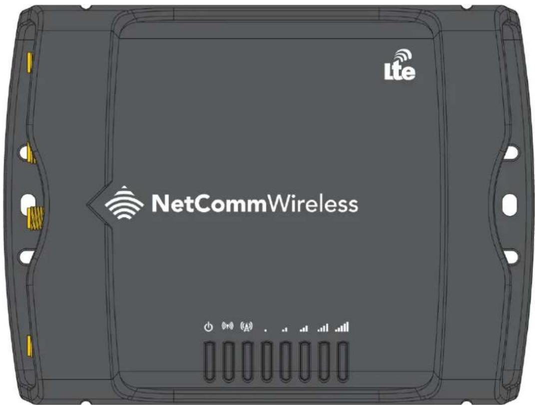
Figure 1 – NTC-140W Series router Dimensions
| NTC-140W SERIES ROUTER(WITHOUT EXTERNAL ANTENNAS ATTACHED) | |
| Length | 143 mm |
| Depth | 107 mm |
| Height | 34 mm |
| Weight | ~235g |
Table 2 - Device Dimensions
LED indicators
The NTC-140W Series router uses 8 LEDs to display the current system and connection status.
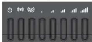
Figure 2 - NTC-140W Series router LED Indicators
| LED ICON | NAME | COLOUR | STATE | DESCRIPTION |
 | Power | Off | Power off | |
| Double flash | Powering up | |||
| On | Power on | |||
| On | Power on in recovery mode | |||
| Slow flashing | Hardware error, such as SIM not inserted | |||
| WiFi | Off | Radio Off | ||
| On | WiFi Access Point is enabled | |||
| Blinking | Traffic via WiFi | |||
| On | Client mode is enabled, WiFi Access Point is disabled | |||
| Blinking | Traffic via WiFi in client mode | |||
| Network | Off | Radio Off | ||
| On | Connected via WWAN | |||
| Blinking ^1 | Traffic via WWAN | |||
| Slow flashing | Connecting PDP | |||
| On | Registered network | |||
| Slow flashing | Registering network | |||
| Slow flashing | SIM PIN locked | |||
| Fast flashing | SIM PUK locked | |||
| On | Can't connect | |||
| Signal strength | On | LTE signal | ||
| On | WCDMA signal | |||
| On | GSM signal |
Table 3 - LED Indicators
Signal strength LEDs
The following table lists the signal strength range corresponding with the number of lit signal strength LEDs.
| NUMBER OF LIT LEDS | SIGNAL STRENGTH |
| All LEDs unlit | <-109 dBm |
| 1 | -109 dBm to -102dBm |
| 2 | -101 dBm to -92 dBm |
| 3 | -91 dBm to -86 dBm |
| 4 | -85 dBm to -78 dBm |
| 5 | ≥ -77 dBm |
Table 4 - Signal strength LED descriptions
LED update interval
The signal strength LEDs update within a few seconds with a rolling average signal strength reading. When selecting a location for the router or connected or positioning an external antenna, please allow up to 20 seconds for the signal strength LEDs to update before repositioning.
Ethernet port LED indicators
Each of the Ethernet ports of the NTC-140W Series router have two LED indicators on them.
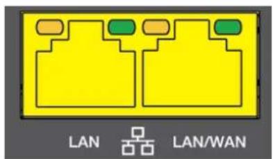
Figure 3 - Ethernet port LED indicators
The table below describes the statuses of each light and their meanings.
| LED | STATUS | DESCRIPTION |
| Green | On | There is a valid network link. |
| Blinking | There is activity on the network link. | |
| Off | No valid network link detected. | |
| Amber | On | The Ethernet port is operating at a speed of 1000Mbps. |
| Off | The Ethernet port is operating at a speed of 10/100Mbps or no Ethernet cable is connected. |
Table 5 - Ethernet port LED indicators description
Interfaces
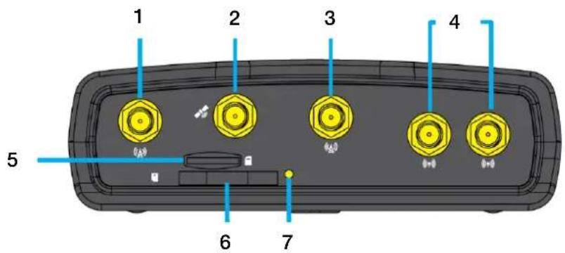
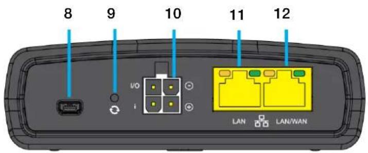
Figure 4 - Interfaces
| NO. | ITEM | DESCRIPTION |
| 1 | Cellular Main antenna connector | SMA connector for main cellular antenna. |
| 2 | GPS antenna connector | SMA connector for GPS antenna (not included in package). |
| 3 | Cellular AUX antenna connector | SMA connector for auxiliary cellular antenna. |
| 4 | WiFi antenna connectors | Reverse polarity SMA connectors for WiFi antennas. |
| 5 | MicroSD card slot | Insert a MicroSD card here to provide additional storage (Optional). |
| 6 | SIM card slot | Insert SIM card here. |
| 7 | SIM tray eject button | Press to eject the SIM tray |
| 8 | Mini USB 2.0 OTG port | Provides connectivity for optional external storage or a USB Ethernet dongle. Supplies up to 0.5A to connected device. |
| 9 | Reset button | Press and hold for less than 5 seconds to reboot to normal mode. The LEDs are green and extinguish in sequence to indicate that the router will reboot normally if the button is released during this period.Press and hold for 5 to 15 seconds to reboot to recovery mode. The LEDs are amber and extinguish in sequence to indicate that the router will reboot to recovery mode if the button is released during this period.Press and hold for 15 to 20 seconds to reset the router to factory default settings. The LEDs are red and extinguish in sequence to indicate that the router will reset to factory default settings if the button is released during this period. |
| 10 | Molex Mini-FitTM Jr. 2 x 2 receptacle | Connect the provided power supply here. The Molex receptacle provides:Ground (-)Power (+)I/O terminal(i) ignition input detection terminal. |
| 11 | LAN port | LAN port for wired Ethernet clients. |
| 12 | LAN/WAN port | LAN or WAN port for wired Ethernet clients or to bridge another network connection. |
Table 6-Interfaces
Placement of the router
The four external high-performance antennas supplied with the router are designed to provide optimum signal strength in a wide range of environments. If you find the signal strength is weak, try adjusting the orientation of the antennas. If you are unable to get an acceptable signal, try moving the router to a different place or mounting it differently.

Note: When selecting a location for the router, allow at least 20 seconds for the signal strength LEDs to update before trying a different location.
Mounting options
The NTC-140W Series router can be quickly and easily mounted in a variety of locations.
Mounted flat against the wall
When mounted flat against the wall, the NTC-140W Series router has a slimline form factor. Use appropriately sized screws in the mounting holes provided on the base of the unit.
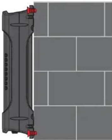
natural_image
Diagram of a mechanical component with red connectors, placed on a grid-patterned surface (no text or symbols)Figure 5 - Wall mount - Flat against the wall
DIN rail mounting bracket
V Bend allows you to snap the DIN bracket onto the middle of a DIN rail rather than sliding it onto the end.

natural_image
Black metal automotive bracket component with mounting holes and mounting brackets (no text or symbols visible)Figure 6 – DIN rail mounting bracket
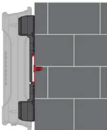
Wall mounted via DIN rail bracket
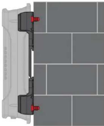
natural_image
Diagram of a vehicle front view with red sensors, showing structural components on a tiled floor (no text or labels)Figure 7 - Wall mounted via DIN rail bracket
DIN rail mount
natural_image
Top-down view of a vehicle's side profile showing front wheel, rear wheel, and dashboard (no text or symbols)Figure 8 - DIN rail mount
Pole mount using DIN rail bracket
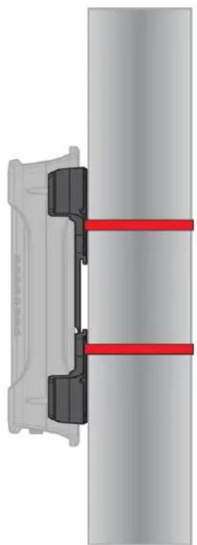
natural_image
Mechanical assembly diagram showing a bracket with red fasteners and two parallel plates (no text or symbols)Figure 9 - Pole mount using DIN rail bracket
Desk mount

natural_image
3D rendering of a mechanical component with mounting base and cylindrical features (no text or symbols)Figure 10 - Desk mount
Installation and configuration of the NTC-140W Series router
Powering the router
The NTC-140W Series router may be powered using the included power supply cable with 8-40V to the Molex connector. A suitable power supply (PSU-0039) is available as an accessory. The diagram below shows the layout of the pins on the Molex connector.
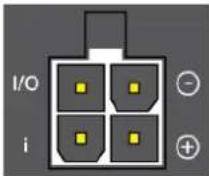
Figure 11 - Molex connector
| TERMINAL | DESCRIPTION |
| - | Ground wire. |
| + | Positive wire for power. |
| i | Dedicated terminal for ignition detection. |
| I/O | Input/output detection. |
Table 7 - Locking power block pin outs
Installing the router
After you have connected a power source and mounted the router, follow these steps to complete the installation process.
-
Connect equipment that requires network access to the LAN port of your router. This may be your computer for advanced configuration purposes, or your end equipment which requires data access via the NTC-140W Series router. You can connect one device directly, or several devices using a network switch.
-
Ensure the external power source is switched on and wait 2 minutes for your NTC-140W Series router to start up. To check the status of your router, compare the LED indicators on the device with those listed in the LED indicators section of this guide.
Advanced configuration
The NTC-140W Series router comes with pre-configured settings that should suit most customers. For advanced configuration, log in to the web-based user interface of the router.
To log in to the web-based user interface:
- Open a web browser (e.g. Internet Explorer, Firefox, Google Chrome), type http://192.168.1.1 into the address bar and press Enter. The web-based user interface log in screen is displayed.
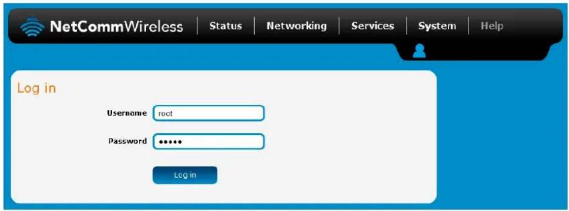
Figure 12—Log in prompt for the web-based user interface
- Enter the login username and password. If this is the first time you are logging in or you have not previously configured the password for the "root" or "admin" accounts, you can use one of the default account details to log in.
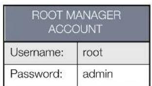
Table 8 - Management account login details – Root manager
| ADMIN MANAGER ACCOUNT | |
| Username: | admin |
| Password: | admin |
Table 9 - Management account login details – Admin manager

Note:
- The admin manager account allows you to manage all settings of the router except functions such as firmware upgrade, device configuration backup and restore and reset to factory default settings, which are privileged only to the root manager account.
- For security reasons, we highly recommend that you change the passwords for the root and admin accounts upon initial installation. You can do so by navigating to the System and then Administration page.
The Status page is displayed when you have successfully logged in.
Status
The status page of the web interface provides system related information and is displayed when you log in to the NTC-140W Series router management console. The status page shows System information, LAN details, Cellular connection status, Packet data connection status, Wireless LAN status and Advanced status details. You can toggle the sections from view by clicking the ▼ or ▲ buttons to show or hide them. Extra status boxes will appear as additional software features are enabled (e.g. VPN connectivity).
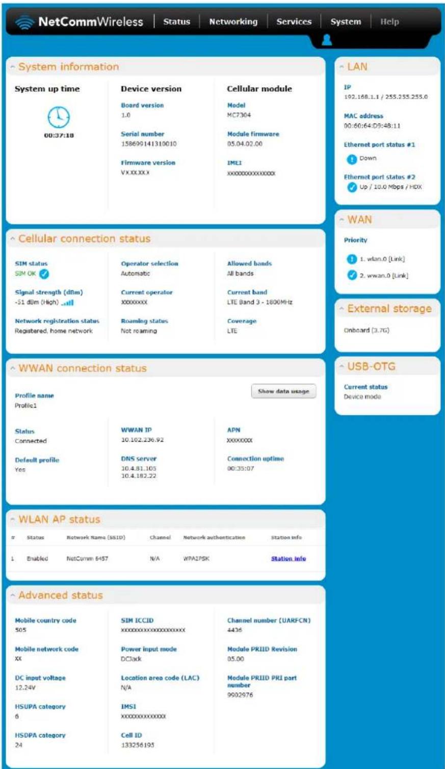
Figure 13 - The Status page
| ITEM | DEFINITION |
| System information | |
| System up time | The current uptime of the router. |
| Board version | The hardware version of the router. |
| Serial Number | The serial number of the router. |
| Firmware version | The firmware version of the router |
| Model | The type of phone module and the firmware version of the module. |
| Module firmware | The firmware revision of the phone module. |
| IMEI | The International Mobile Station Equipment Identity number used to uniquely identify a mobile device. |
| LAN | |
| IP | The IP address and subnet mask of the router. |
| MAC Address | The MAC address of the router. |
| Ethernet Port Status | Displays the current status of the Ethernet port and its operating speed. |
| WAN | |
| Priority | Displays the priority of the available WAN connections. |
| External Storage | Lists the type and size of external storage (onboard/USB), if connected. |
| USB-OTG | Displays the current status of the USB-OTG port (Device or host mode) |
| Cellular connection status | |
| SIM Status | Displays the activation status of the SIM in the router. |
| Signal strength (dBm) | The current signal strength measured in dBm |
| Network registration status | The status of the router's registration for the current network. |
| Operator selection | The mode used to select an operator network. |
| Current operator | The current operator network in use. |
| Roaming status | The roaming status of the router. |
| Allowed bands | The bands to which the router may connect. |
| Current band | The current band being used by the router. |
| Coverage | The type of mobile coverage being received by the router. |
| WWAN Connection Status | |
| Profile name | The name of the active profile. |
| Status | The connection status of the active profile. |
| Default profile | Indicates whether the current profile in use is the default profile. |
| WWAN IP | The IP address assigned by the mobile broadband carrier network. |
| DNS server | The primary and secondary DNS servers for the WWAN connection. |
| APN | The Access Point Name currently in use. |
| Connection uptime | The length of time of the current mobile connection session. |
| WLAN status | |
| Status | Shows the current status of the wireless LAN network. |
| Network Name (SSID) | Shows the network name (SSID) of the wireless network. |
| Channel | Shows the channel that the wireless network is configured to operate on. |
| Network authentication | The type of security/encryption in use on the wireless network. |
| Station Info | Click the Station Info link to be taken to the station information page providing more information on the connected stations. |
| Advanced status | |
| Mobile country code | The Mobile Country Code (MCC) of the router. |
| Mobile network code | The Mobile Network Code (MNC) of the router. |
| DC input voltage | Displays the current voltage of the power input source provided via the DC Input jack |
| HSUPA category | Displays the HSUPA category (1-9) for the current uplink |
| HSDPA category | Displays the HSDPA category (1-8) for the current downlink. |
| SIM ICCID | The Integrated Circuit Card Identifier of the SIM card used with the router, a unique number up to 19 digits in length. |
| Power input mode | Displays the power source being used. |
| Location area code (LAC) | The ID of the cell tower grouping the current signal is broadcasting from. |
| IMSI | The International mobile subscriber identity is a unique identifier of the user of a cellular network. |
| Cell ID | A unique code that identifies the base station from within the location area of the current mobile network signal. |
| Channel number (UARFCN) | The channel number of the current cellular connection. |
| CID | Cellular configuration ID |
| Module PRIID Revision | Module version used for customization. |
| Module PRIID PRI part number | The part number of the Module PRIID. |
Table 10 - Status page item details
Networking
The Networking section provides configuration options for Wireless WAN, LAN, Routing and VPN connectivity.
Data Connection
The data connection page allows you to configure and enable/disable the connection profile. To access this page, click on the Networking menu, and under the Wireless WAN menu, select the Data connection item.

Figure 14 – Data connection settings
| ITEM | DEFINITION |
| Data connection | |
| Transparent Bridge (PPPoE) | Toggles the transparent bridge function on and off. |
| Profile name list | |
| Default | Sets the corresponding profile to be the default gateway for all outbound traffic except traffic for which there are configured static route rules or profile routing settings. |
| Status | Toggles the corresponding profile on and off. Only one profile may be turned on at any time.. |
| APN | The APN configured for the corresponding profile. |
| Username | The username used to log on to the corresponding APN. |
| Roaming settings | |
| Allow data roaming | When set to ON, the router will allow local devices to access the Wireless WAN network when the it is roaming onto a foreign network. When set to OFF, the router will deny network access to data services when roaming onto a foreign network. This setting is OFF by default. |
Table 11 - Data connection item details
Connecting to the mobile broadband network
The router supports the configuration of up to six APN profiles; these profiles allow you to configure the settings that the router will use to connect to the broadband network and switch easily between different connection settings.
Manually configuring a connection profile
To manually configure a connection profile:
- Click the Edit button corresponding to the Profile that you wish to modify. The data connection profile settings page is displayed.
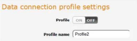
Figure 15 - Data connection profile settings
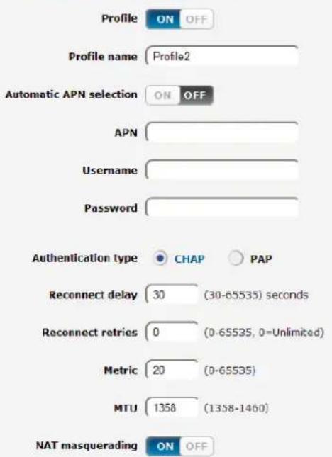
- Click the Profile toggle key to turn the profile on. Additional settings appear.
Data connection profile settings
Profile routing settings
You may route only particular traffic via this connection profile by specifying the network address and mask below of the destination network. Blank values will route all traffic via this profile. Please leave these settings blank if you are unsure.
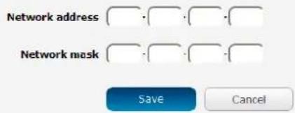
Figure 16 - Data connection settings - Profile turned on
-
In the Profile name field, enter a name for the profile. This name is only used to identify the profile on the router.
-
Ensure that the Automatic APN selection toggle key is set to off. If it is not, click it to toggle it to the off position.
-
In the APN field, enter the APN Name (Access Point Name) and if required, use the Username and Password fields to enter your login credentials.
-
Next to Authentication type, select either CHAP or PAP depending on the type of authentication used by your provider.
-
The Reconnect delay field specifies the number of seconds to wait between connection attempts. The default setting of 30 seconds is sufficient in most cases but you may modify it to wait up to 65535 seconds if you wish.
-
The Reconnect retries field specifies the number of times to attempt a network connection if the router fails to establish a connection. It is set to 0 by default which causes the router to attempt to reconnect indefinitely.
-
The Metric value is used by router to prioritise routes (if multiple are available) and is set to 20 by default. This value is sufficient in most cases but you may modify it if you are aware of the effect your changes will have on the service.
-
The MTU field allows you to modify the Maximum Transmission Unit used on the connection. Do not change this unless instructed to by your carrier.
-
Use the NAT Masquerading toggle key to turn NAT Masquerading on or off. NAT masquerading, also known simply as NAT is a common routing feature which allows multiple LAN devices to appear as a single WAN IP via network address translation. In this mode, the router modifies network traffic sent and received to inform remote computers on the internet that packets originating from a machine behind the router actually originated from the WAN IP address of the router's internal NAT IP address. This may be disabled if a framed route configuration is required and local devices require WAN IP addresses.
-
Click the Save button when you have finished entering the profile details.
Confirming a successful connection
After configuring the packet data session, and ensuring that it is enabled, click on the Status menu item at the top of the page to return to the Status page. When there is a mobile broadband connection, the WWAN section is expanded showing the details of the connection and the Status field displays Connected. To see details on the connected session, you can click the Show data usage button.
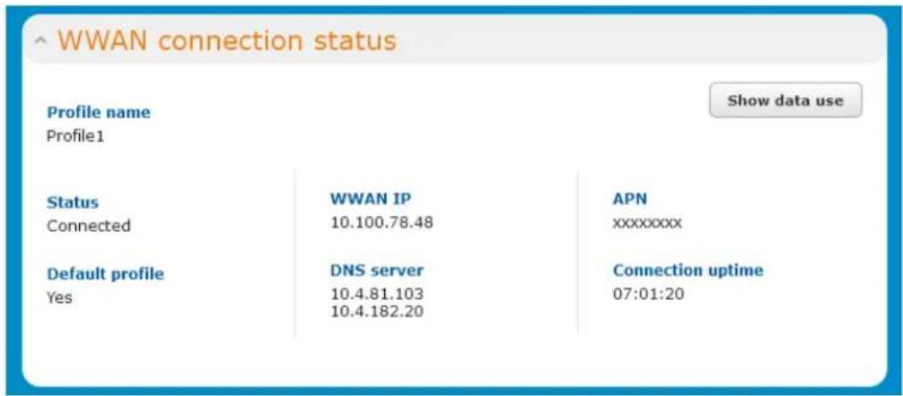
Figure 17 - WWAN connection status section
Transparently bridging the mobile broadband connection via PPPoE
If desired, you can have a client device connected to the Ethernet port initiate the mobile broadband connection using a PPPoE session. This is particularly useful in situations where you wish to provide Wireless WAN data access to an existing router which you want to have full public WAN IP access and have control over routing functionality.
To enable transparent bridging via PPPoE:
- Click the Networking menu item from the top menu bar.
- On the Data connection page, click the Transparent bridge (PPPoE) toggle key so that it is ON.
Data connection
Transparent bridge (PPPoE)

OFF
In this mode the unit acts as an Ethernet Bridge instead of as an IP Router. This is facilitated by PPPoE which forwards the WAN IP/DNS information to a downstream LAN device and facilitates transparent network connectivity. To use this feature, you need to initiate a PPPoE client connection from a downstream device (such as a Ethernet Router or computer) which is then accepted by the router. The router operates a PPPoE server and will activate a PDP context using the username/password from the PPPoE client connection and the APN configured on this page. This allows control over the PDP context activation by the downstream device. Once enabled in this mode, some router functionality will no longer be applicable and will cease to function (e.g Connect on demand, routing, VPN, TR-069, Router firewall, remote access, and others). Only a single downstream device is permitted Wireless WAN connectivity and all traffic is forwarded to that device. Please note in this mode, the downstream device is responsible for all network security as the built-in firewall has no effect.
Transparent bridge mode configuration
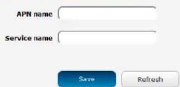
Figure 18 - Transparent bridge configuration
- In the APN name field, enter the APN that you wish to use for the mobile broadband connection.
- (Optional) In the Service name field, enter a name that allows you to easily identify the connection.
- Click the Save button to confirm the settings.
- Click the Status menu item from the top menu bar to see the transparent bridging status.
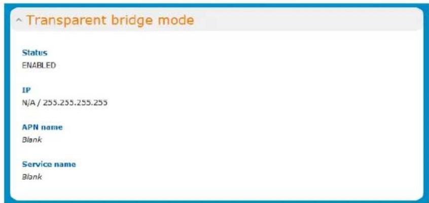
Figure 19 - Transparent bridge mode status
- Next you must configure your downstream device connected via Ethernet to the NTC-140W to initiate a network connection using a PPPoE client. The username and password used by the downstream device for the PPPoE session will be passed on and used by the NTC-140W as the packet data (PDP) context authentication settings.
Connect on demand
The Connect on demand feature keeps the Packet Data Protocol (PDP) context deactivated by default while making it appear to locally connected devices that the router has a permanent connection to the mobile broadband network. When a packet of interest arrives or an SMS wake-up command is received, the router attempts to establish a mobile broadband data connection. When the data connection is established, the router monitors traffic and terminates the link when it is idle.

Note: When interesting packets arrive, the recovery time for the wireless WAN connection is approximately 20-30 seconds.
Configuring Connect on demand
To configure Connect on demand:
- Click the Networking menu item from the top menu bar.
- On the Connect on demand page, click the Connect on demand toggle key so that it is ON. Extra options appear. See the following sub-sections for further instructions.
Connect on demand
The connect on demand feature keeps the PDP context deactivated by default while making it appear that the router has permanent connection to WWAN and locally connected devices. When interesting packets arrive or an SMS wake-up command is received, the router will attempt to establish a WWAN data connection. The router will monitor traffic once the data connection is established and will terminate it when the link is idle.
Connect on demand


Data activity triggered connection
Connect only when traffic appears to these UDP/TCP destination ports. You can specify multiple ports by separating them with a comma (eg 21, 23, 53).
Enable dial port filter


Connect on data activity except when activity matches these IP protocols
Ignore ICMP


Ignore TCP


Ignore UDP


on data activity except when activity matches these applications
Ignore DNS


Ignore NTP


Ignore Microsoft network awareness (NCST) traffic


Connect and disconnect timers Periodic connect schedule
On data activity, stay online for at least
20 minutes

After connecting, stay online for at least
20 minutes

After hanging up, don't redial for
5 seconds

Disconnect regardless of traffic after
never

Connect regularly, every
never

Randomise connect frequency by up to


Verbose logging configuration
Log all matched activity to the system log


Online / Offline control
Online status Disabled

Manual disconnect
Cancel
Figure 20 - Connect on demand configuration options
Setting the router to dial a connection when traffic is detected on specific ports
In some situations, you may wish to have the internet connection disabled except at times when outbound traffic to a particular external host's port or group of ports is sent to the router. To use this feature, click Enable dial port filter and enter the port number or list of port numbers separated by commas. When you select this option, all outbound ICMP/TCP/UDP packets to any remote host on the specified port(s) will trigger the connection to dial. Note that when this feature is enabled, the options to ignore specific packet types are not available.
Data activity triggered connection
Connect only when traffic appears to these UDP/TCP destination ports. You can specify multiple ports by separating them with a comma (eg 21, 23, 53).

Figure 21 - Connect on demand - Data activity triggered connection
You can allow Microsoft network awareness (NCSI) traffic through but if you prefer that they do not trigger the connection, click the Ignore Microsoft network awareness (NCSI) traffic toggle key to set it to ON.
Connect on data activity except when activity matches these applications
Ignore Microsoft network awareness (NCSI) traffic

Figure 22 - Connect on demand - Ignore NCSI traffic
Excluding certain packet types from triggering the connection to dial
Depending on your environment, you might prefer to exclude certain types of traffic passing through the router from triggering the data connection. You can tell the router to ignore outbound TCP, UDP or ICMP packets. When any of these options are checked the router will not dial a connection when that type of outbound destined data packet reaches the router from a locally connected device.
Connect on data activity except when activity matches these IP protocols
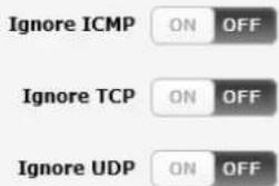
Figure 23 - Connect on demand - Excluding IP protocols
Excluding certain application types from triggering the connection to dial
Some devices may generate general traffic as a part of normal operation which you may not want to trigger the data connection. You can set the router to ignore Domain Name System (DNS), Network Time Protocol (NTP) or Microsoft network awareness (NCSI) traffic from devices behind the router. When you check the box for these options, it tells the router to ignore the request from that application type and will not dial a connection when this data type is received.
on data activity except when activity matches these applications
Ignore DNS

Ignore NTP

Ignore Microsoft network awareness (NCSI) traffic

Figure 24 - Connect on demand - Excluding application types
Setting timers for connection and disconnection
The router has a number of timer settings which let you determine when a connection is dialled and when it is disconnected.
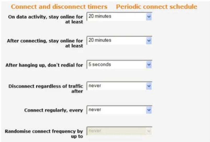
Figure 25 - Connect on demand - Connect and disconnect timers
| OPTION | DESCRIPTION |
| On data activity, stay online for at least | When traffic as per the configured settings above appear, the router will either continue to stay online, or dial a connection and will not disconnect it for the specified time period (min. 1 minute, max. 1 hour). This timer is continuously reset throughout the duration of a dial-up session, whenever data activity is detected matching the rules above. |
| After connecting, stay online for at least | This timer configures the router to not hang-up the connection for the specified time period after initially dialling the connection. This setting cannot be less than the keep online period above. This timer affects the connection only once per dial up session, at the beginning of the session. |
| After hanging up, don't redial for | After a connection has been disconnected, you can tell the router to rest for a period of time before re-dialling. |
| Disconnect regardless of traffic after | Forces the router to disconnect the connection regardless of the traffic passing through it. The default setting is never. |
| Connect regularly, every / Randomise connect frequency by up to | If you want to have the router dial a connection at regular intervals, use Connect regularly, every to specify the interval between dials. Setting this to never effectively disables this option.The router also features the ability to randomise the time at which the first dial action is performed. This is useful in situations such as where you have numerous routers in an area where a power outage has occurred. Setting a random dial time helps to reduce network congestion when all the routers are powered on so they do not all try to connect simultaneously.When Connect regularly, every is set to at least 2 minutes, you are able to configure the router to randomise the time it begins to dial. The randomised dial timer only affects the initial dial after the unit powers on or after the settings are saved. For example, if you configure the router to dial every 2 minutes with a randomised dial starting time of 1 minute, the router waits for the Connect regularly, every time (2 minutes) and then randomly selects a time less than or equal to the Randomise connect frequency by up to time (1 minute). After the randomly selected time has elapsed, the router dials the connection. After the first dial, the router dials the connection every 2 minutes, ignoring the Randomise connect frequency by up to time. |
Table 12 - Connect on demand - Connect and disconnect timers descriptions
Verbose mode
The router provides the option of logging all the data activity which matches the settings for the Connect on demand feature for advanced troubleshooting purposes. To enable the logging of the Connect on demand feature, click the Enable verbose mode toggle key to switch it ON. See the System log section for more information.

Figure 26 - Connect on demand - Verbose logging configuration
Manually connecting/disconnecting
There may be times when you need to either force a connection to be made or force a disconnection manually. You can use the Manual connect and Manual disconnect buttons to do this whenever necessary. The online status of the connection is displayed above the buttons.
Online / Offline control
Online status Disabled
Manual connect
Manual disconnect
Figure 27 - Connect on demand - Online/Offline control
When you have finished configuring the options for the Connect on demand feature, click the Save button at the bottom to save your changes.
SMS Wake up
The router can also be woken up by means of an SMS message using the SMS diagnostics feature by sending an executable wakeup command via SMS. See the Diagnostics section for details on using the SMS Wake up function.
SIM Management
The SIM management page allows you to specify the primary SIM to use in the case where you have a soldered down SIM card and a SIM inserted into the SIM tray. To change the preference of the SIMs, use the arrow button to the right of SIM2 to switch priorities and click the Save button.
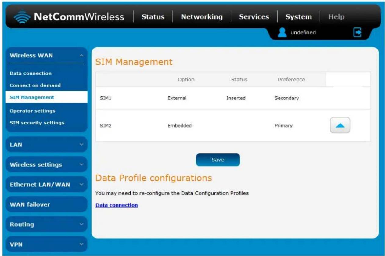
Figure 28 - SIM Management
Operator settings
The Operator settings page enables you to select which frequency band you will use for your connection and enables you to scan for available network operators in your area.
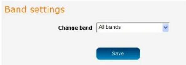
Figure 29 - Band settings

Note: In order to change the operator's band settings, the data connection must be disabled. When you access this page, you are prompted to disable the data connection if it is already active.
You may want to do this if you're using the router in a country with multiple frequency networks that may not all support High Speed Packet Access (HSPA). You can select the router to only connect on the network frequencies that suit your requirements.
Use the Change band drop down list to select the band you wish to use.
The following band settings options are available:
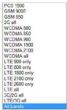
It is not necessary to change the default setting of All bands in most cases. In fact, locking to a particular band can cause connection difficulties if the device is moved to a location where the forced band selection is no longer available.
When All bands is selected, the router attempts to find the most suitable band based on the available networks for the inserted SIM card.
The "2G all", "WCDMA all", "LTE all", "3G/2G all" and "LTE/3G all" options allow you to force the device to lock to those particular networks only.
Click the Save button to save and apply your selection.
Operator settings
The operator settings feature allows you perform a scan of available networks, and to optionally lock to a particular network returned by the network scan. To scan for available networks, set the Select operator mode from automatic to Manual then click the scan button. This operation can take a few minutes and requires that the packet data session be disconnected prior to scanning.
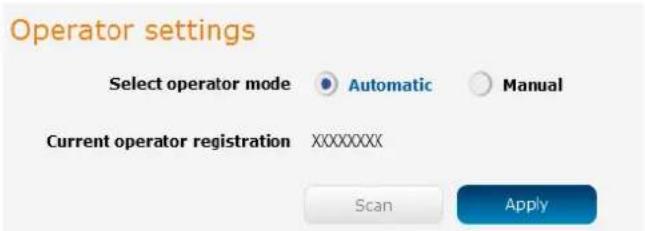
Figure 30 - Operator settings
A list of the detected cellular service carriers in your area is displayed.
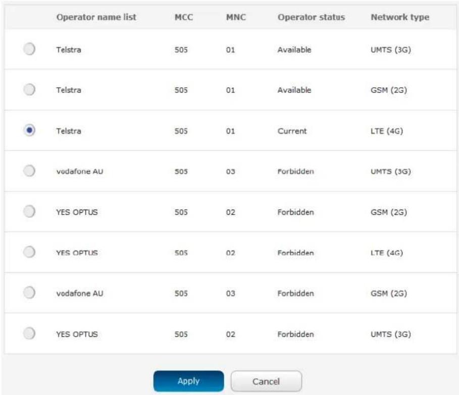
Figure 31 - Detected operator list
Select the most appropriate service from the list shown and click Apply.
When Select operator mode is set to Automatic, the router selects the most appropriate operator based on the inserted SIM card. This is the default option and is sufficient for most users.
SIM security settings
The SIM security settings page can be used for authenticating SIM cards that have been configured with a security PIN.
Unlocking a PIN locked SIM
If the SIM card is locked, you will receive a notice when you access the Status page after which you will be directed to the PIN settings page to enter the PIN. The PIN settings page lists the status of the SIM at the top of the page.
If you are not redirected to the PIN settings page, to unlock the SIM:
a) Click on the Networking menu from the top menu bar, and then click SIM security settings.
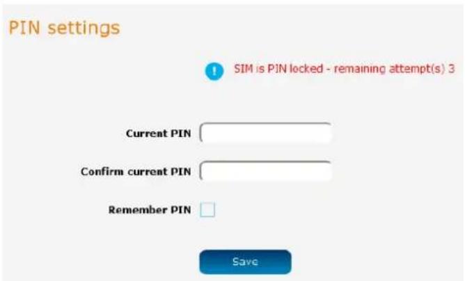
Figure 32 - SIM security settings - SIM PIN locked
b) Enter the PIN in the Current PIN field and then enter it again in the Confirm current PIN field to confirm the PIN.
c) If you are placing the router in a remote, unattended location, you may wish to check the Remember PIN option. This feature allows the router to automatically send the PIN to the SIM each time the SIM asks for it (usually at power up). This enables the SIM to be PIN locked (to prevent unauthorised re-use of the SIM elsewhere), while still allowing the router to connect to the cellular service.
When this feature is enabled, the PIN you enter when setting the Remember PIN feature is encrypted and stored locally on the router. The next time the SIM asks the router for the PIN, the router decrypts the PIN and automatically sends it to the SIM without user intervention.
When this feature is disabled and the SIM is PIN locked and the PIN must be manually entered via the router's configuration interface. In situations where the router will be unattended, this is not desirable.

Note: Select Remember PIN if you do not want to enter the PIN code each time the SIM is inserted.
d) Click the Save button. If successful, the router displays the following screen:
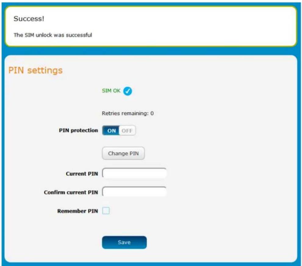
Figure 33 - SIM security settings - SIM unlock successful
Enabling/Disabling SIM PIN protection
The security PIN protection can be turned on or off using the PIN protection toggle key.
PIN settings
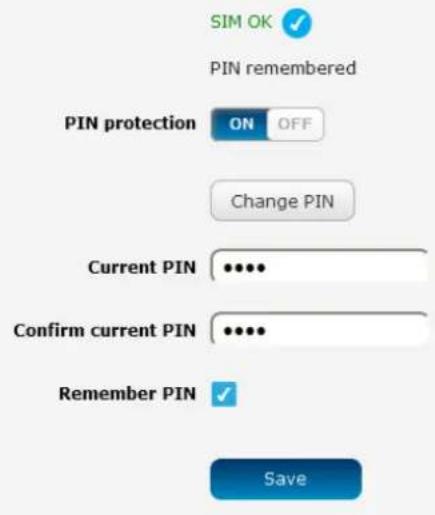
Figure 3-4 - PIN Settings
Changing the SIM PIN code
If you would like to change the PIN, click the Change PIN button and enter the current PIN into the Current PIN and Confirm current PIN fields, then enter the desired PIN into the New PIN and Confirm new PIN fields and click the Save button.
PIN settings
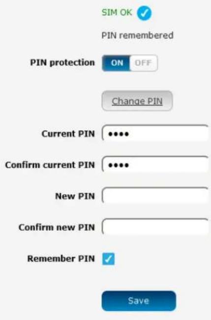
Figure 35 - PIN settings - Change PIN
When the PIN has been changed successfully, the following screen is displayed:
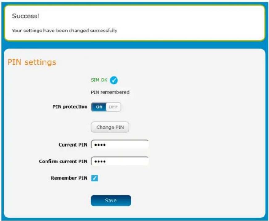
Figure 36 - SIM security settings – PIN unlock successful
Unlocking a PUK locked SIM
After three incorrect attempts at entering the PIN, the SIM card becomes PUK (Personal Unblocking Key) locked and you are requested to enter a PUK code to unlock it.

Note: To obtain the PUK unlock code, you must contact your service provider.
You will be issued a PUK to enable you to unlock the SIM and enter a new PIN. Enter the new PIN and PUK codes. Click the Save button when you have finished entering the new PIN and PUK codes.
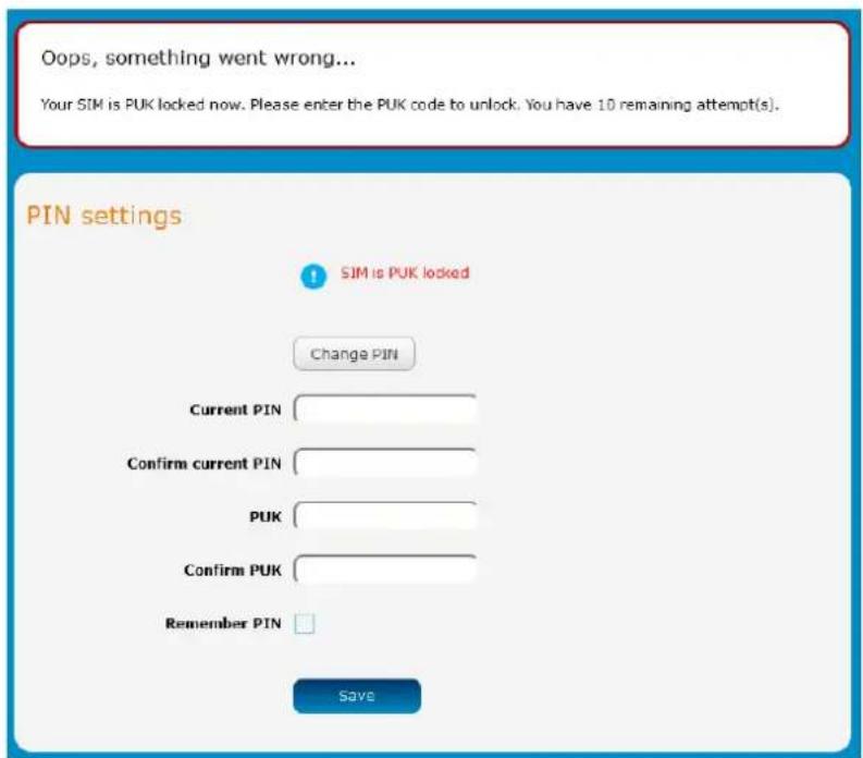
Figure 37 - SIM security - SIM PUK locked
LAN
LAN configuration
The LAN configuration page is used to configure the LAN settings of the router and to enable or disable DNS Masquerading.
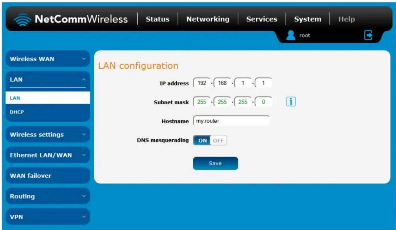
Figure 38 – LAN configuration settings
The default IP of the LAN port is 192.168.1.1 with subnet mask 255.255.255.0. To change the IP address or Subnet mask, enter the new IP Address and/or Subnet mask and click the Save button.

Note: If you change the IP address, remember to reboot the router and enter the new IP address into your browser address bar.
DNS masquerading
DNS masquerading allows the router to proxy DNS requests from LAN clients to dynamically assigned DNS servers. When enabled, clients on the router's LAN can then use the router as a DNS server without needing to know the dynamically assigned cellular network DNS servers.
With DNS masquerading ON, the DHCP server embedded in the NTC-140W Series router hands out its own IP address (e.g. 192.168.1.1) as the DNS server address to LAN clients. The downstream clients then send DNS requests to the NTC-140W Series router which proxies them to the upstream DNS servers.
With DNS masquerading OFF, the DHCP server hands out the upstream DNS server IP addresses to downstream clients directly, so that downstream clients send DNS requests directly to the upstream DNS servers without being proxied by the NTC-140W Series router.
You may also override the DNS Masquerading option by specifying custom DNS Server IP addresses in the DHCP Server configuration mentioned in the next section of this guide. In this case the DHCP server assigns downstream devices the manually configured addresses and the DNS Masquerading option is ignored.
In most cases, it is not necessary to disable DNS masquerading but if you need to, click the DNS masquerading toggle key to turn it OFF and then click the Save button.
DHCP
The DHCP page is used to adjust the settings used by the router's built in DHCP Server which assigns IP addresses to locally connected devices.
DHCP relay configuration
In advanced networks configurations where the NTC-140W Series router should not be responsible for DHCP assignment, but instead an existing DHCP server is located on the Wireless WAN or LAN connections, the clients behind the NTC-140W Series router are able to communicate with the DHCP server when DHCP relay is enabled. This enables the NTC-140W Series router to accept client broadcast messages and to forward them onto another subnet.
To configure the router to act as a DHCP relay agent click the DHCP relay toggle key to turn it ON and enter the DHCP server address into the DHCP server address field. DHCP relay is disabled by default.
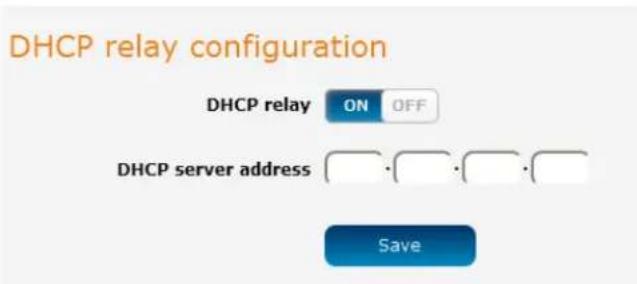
Figure 39 - DHCP relay configuration
DHCP configuration
You can manually set the start and end address range to be used to automatically assign addresses within, the lease time of the assigned address, the default domain name suffix, primary and secondary DNS server, the primary and secondary WINS server, as well as the advanced DHCP settings such as NTP, TFTP and Option 150/Option 160 (VoIP options).
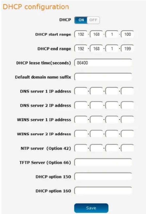
| OPTION | DESCRIPTION |
| DHCP start range | Sets the first IP address of the DHCP range |
| DHCP end range | Sets the last IP address of the DHCP range |
| DHCP lease time (seconds) | The length of time in seconds that DHCP allocated IP addresses are valid |
| Default domain name suffix | Specifies the default domain name suffix for the DHCP clients. A domain name suffix enables users to access a local server, for example, server1, without typing the full domain name server1.domain.com |
| DNS server 1 IP address | Specifies the primary DNS (Domain Name System) server's IP address. |
| DNS server 2 IP address | Specifies the secondary DNS (Domain Name System) server's IP address. |
| WINS server 1 IP address | Specifies the primary WINS (Windows Internet Name Service) server IP address |
| WINS server 2 IP address | Specifies the secondary WINS (Windows Internet Name Service) server IP address |
| NTP server (Option 42) | Specifies the IP address of the NTP (Network Time Protocol) server |
| TFTP Server (Option 66) | Specifies the TFTP (Trivial File Transfer Protocol) server |
| DHCP option 150 | This is used to configure Cisco IP phones. When a Cisco IP phone starts, if it is not pre-configured with the IP address and TFTP address, it sends a request to the DHCP server to obtain this information. Specify the string which will be sent as a reply to the option 150 request. |
| DHCP option 160 | This is used to configure Polycom IP phones. When a Polycom IP phone starts, if it is not pre-configured with the IP address and TFTP address, it sends a request to the DHCP server to obtain this information. Specify the string which will be sent as a reply to the option 160 request. |
Enter the desired DHCP options and click the Save button.
Address reservation list
DHCP clients are dynamically assigned an IP address as they connect, but you can reserve an address for a particular device using the address reservation list.
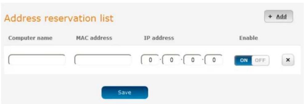
Figure 41 - DHCP - Address reservation list
To add a device to the address reservation list:
- Click the +Add button.
- In the Computer Name field enter a name for the device.
- In the MAC Address field, enter the device's MAC address.
- In the IP Address fields, enter the IP address that you wish to reserve for the device.
- If the Enable toggle key is not set to ON, click it to switch it to the ON position.
- Click the Save button to save the settings.
Dynamic DHCP client list
The Dynamic DHCP client list displays a list of the DHCP clients. If you want to reserve the current IP address for future use, click the Clone button and the details will be copied to the address reservation list fields. Remember to click the Save button under the Address reservation list section to confirm the configuration.
Dynamic DHCP client list
| Computer name | MAC address | IP address | Expiry time |
| xxxxxx | 00:21:9b:1a:89:ee | 192.168.1.146 | Thursday, 5September 201312:02:59 PMClone |
Figure 42 - Dynamic DHCP client list
Wireless settings
The Wireless settings pages allow you to configure the WiFi settings of the router. The NTC-140W is capable of running both access point and wireless client modes simultaneously, however, they must both use the same channel number.
AP basic
The AP basic page provides options such as for turning the WiFi access point on or off, modes of operation, frequency and security settings.
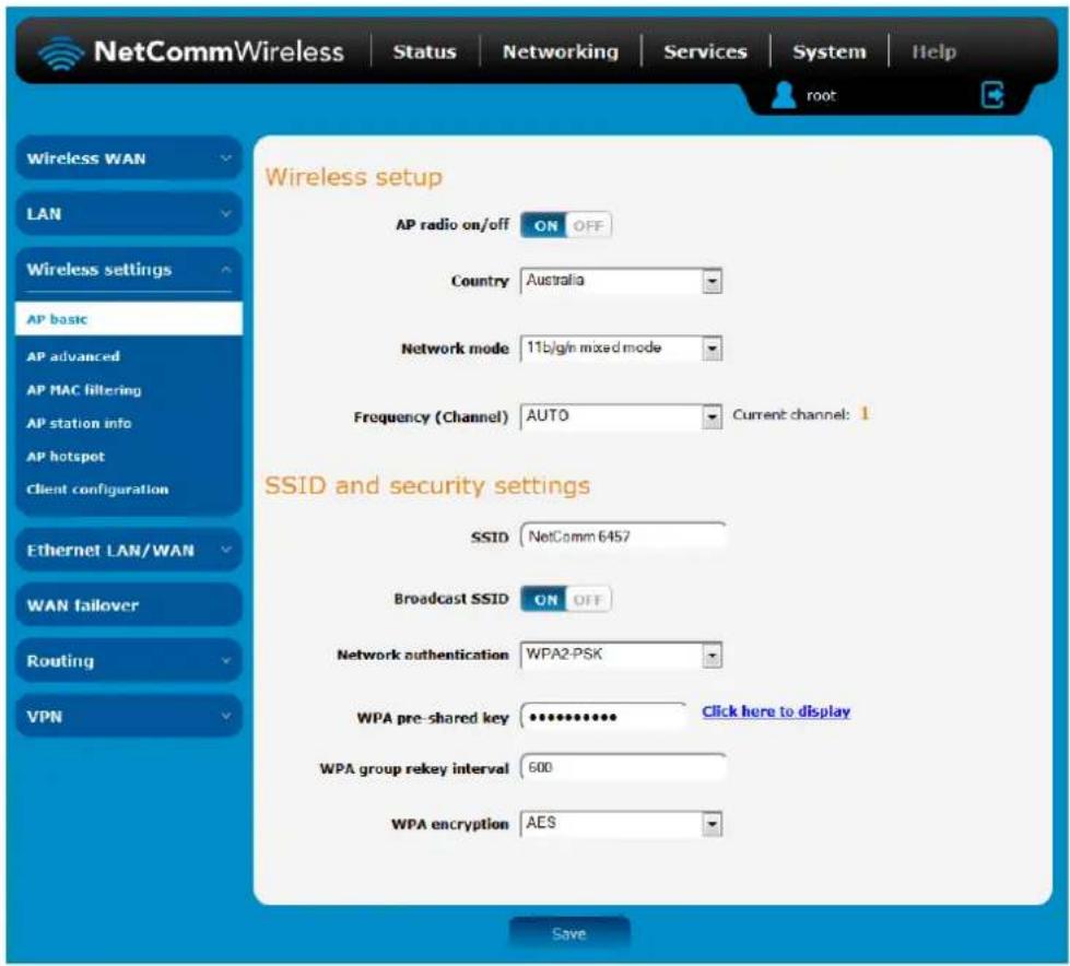
Figure 43 - Wireless Settings - Basic
| OPTION | DEFINITION |
| Wireless setup | |
| AP radio on/off | The WiFi access point is turned on by default. Changing this option to OFF will turn OFF the wireless access point functionality of the NTC-140W and you will not be able to connect to it with a wireless client. |
| Country | Select the country you are operating the NTC-140W in. |
| Network mode | There are 6 possible network modes to use depending on the capability of your devices' wireless network cards. Each mode represents one or more wireless network protocols. Each wireless device will be capable of receiving some but possibly not all of wireless broadcast protocol types. They are:802.11b/g/n mixed mode.802.11b only.802.11g only.802.11n only.802.11b/g/n mixed mode. |
| Frequency (Channel) | Select the wireless channel of the access point that the wireless signal will broadcast on. |
| SSID and security settings | |
| SSID | The SSID or network name of the wireless network. Refer to the included Wireless Security Card for the default SSID of the router. |
| Network authentication | The wireless security settings. See below for in depth analysis. |
| WPA pre-shared key | The wireless security key or wireless password. |
| WPA group rekey interval | The time in seconds before a new key is generated. |
| WPA encryption | The type of WPA encryption. Options include AES, TKIP or TKIP + AES. |
Table 13 - Wireless Configuration - Basic Configuration Items
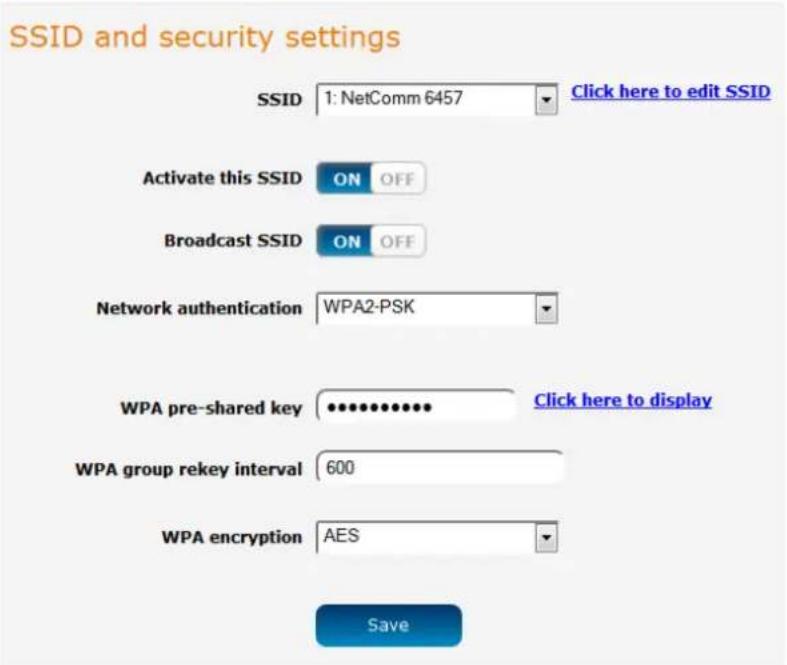
Figure 44 - Wireless Settings - SSID and Security Settings
| OPTION | DEFINITION |
| SSID | The SSID (Service Set Identifier) or Network Name in use for the wireless network. |
| Activate this SSID | Enables or disables the network selected in the SSID drop down list. |
| Broadcast SSID | Toggles whether the router broadcasts the SSID or whether it is hidden from wireless network scans. |
| Network Authentication | The wireless security settings. See below for in depth analysis. |
| WPA pre-shared key | The wireless security key or wireless password. |
| WPA group rekey interval | The time in seconds before a new key is generated. |
| WPA encryption | The type of WPA encryption. Options include AES, TKIP or TKIP + AES. |
Table 14 - Wireless Settings – SSID and Security Settings
AP advanced
The advanced wireless configuration page allows you to modify advanced wireless access point settings of your router. These settings are set to optimal settings for most situations and should not be changed unless you are aware of the effect that your changes will have.
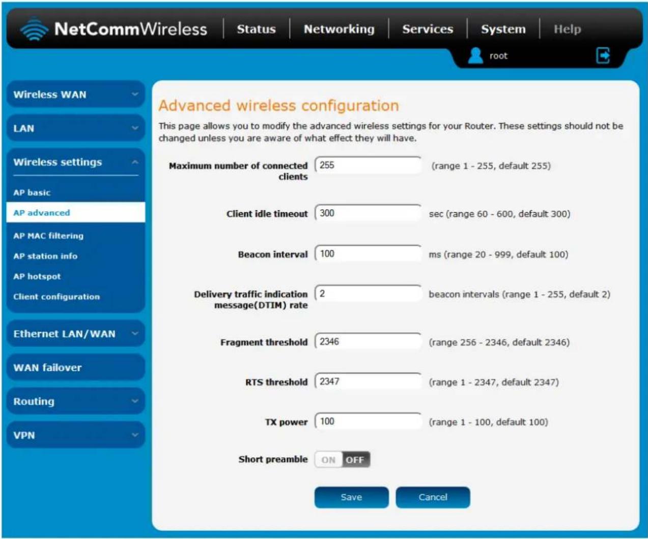
Figure 45 - Wireless Settings - Advanced
| OPTION | DEFINITION |
| Maximum number of connected clients | The maximum number of wireless clients that may connect to the access point. This may be a maximum of 255. |
| Client ide timeout | The time in seconds that a wireless client session can be idle before the router cancels the session and defines the wireless client as not connected. |
| Beacon interval | Interval of time in which the wireless router broadcasts a beacon which is used to synchronize the wireless network. |
| Delivery traffic indication message (DTIM) rate | Enter a value in milliseconds between 1 and 255 for the Delivery Traffic Indication Message (DTIM). A DTIM is a countdown informing clients of the next window for listening to broadcast and multicast messages. |
| Fragment threshold | This specifies the maximum size of a packet during the fragmentation of data to be transmitted. if you set this value too low, it will result in bad performance. |
| RTS threshold | When the packet size is smaller than the RTS threshold, the wireless router will not use the RTS/CTS mechanism to send this packet. |
| TX power | This determines the transmitting or output power of the antenna. |
| Short preamble | Enable or disable short preambles in use on the wireless network. Using short preambles should improve throughput, however some wireless network adapters must use long preambles. |
Table 15 - Wireless Settings - Advanced Configuration Items
AP MAC filtering
The Wireless LAN AP MAC filter feature ensures the network accessibility for the wireless client devices can be controlled. When the MAC filter is enabled with an Allow policy only those wireless clients whose MAC address is listed in the MAC filter list will be able to gain network access. All other wireless client devices will be denied network access. When the MAC filter is enabled with a Block policy all wireless client devices listed whose MAC address is listed in the MAC filter list will be denied network access. All other wireless client devices will be allowed network access.
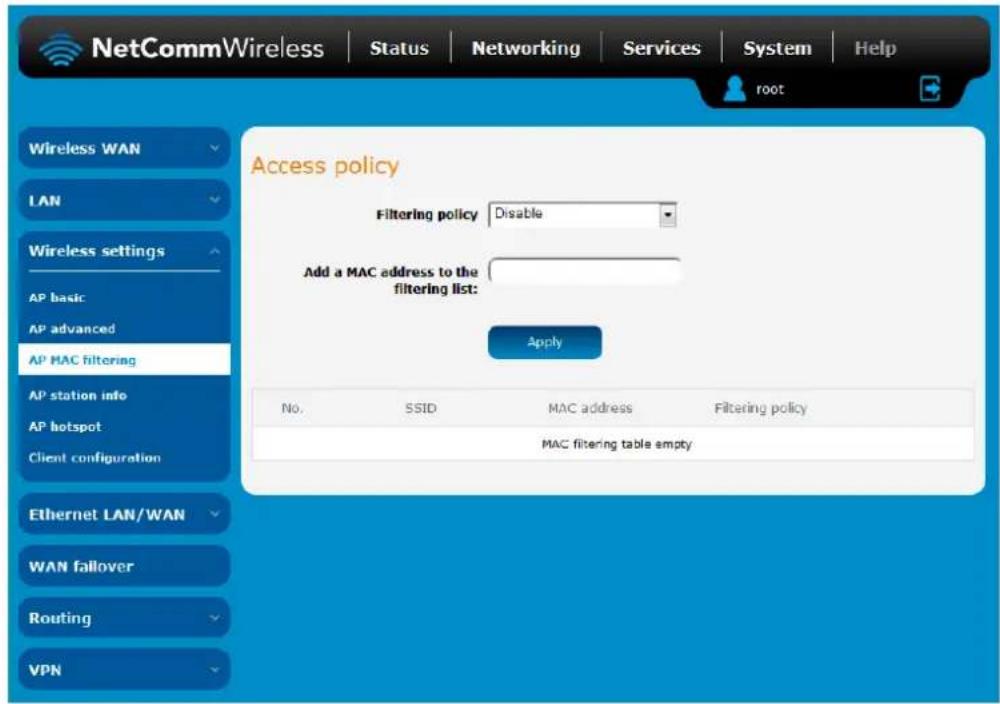
Figure 46 - MAC Filtering
AP station info
The Station info page shows the number of devices currently connected to your NTC-140W via Wireless. The MAC address, Host Name and IP address of these devices are displayed.
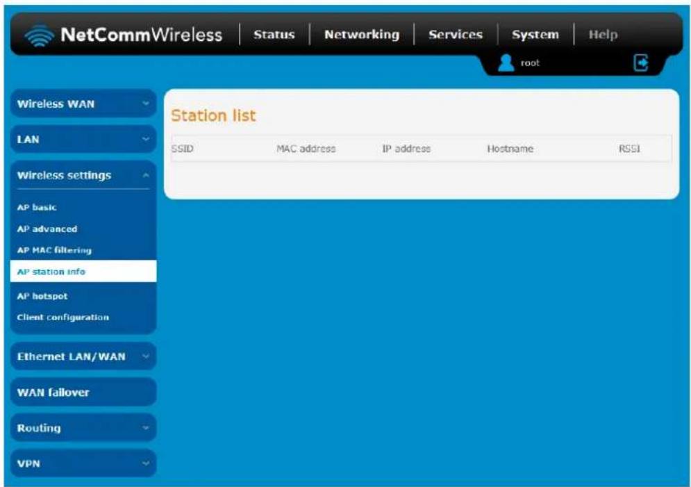
Figure 47 - Wireless Station List
AP hotspot
The wireless hotspot feature provides internet access to WiFi clients with the option of forcing users to agree to terms of use. This feature is often used where wireless access is provided to customers in a public area and allows you to configure a speed limit on the network, limit the number of clients, configure idle and session timeouts and select to authenticate with remote RADIUS servers.

Note: When using the Hotspot feature, we recommend that you set the Network authentication mode on the Basic page for the Hotspot's SSID to Open so that wireless users are not made to authenticate twice.
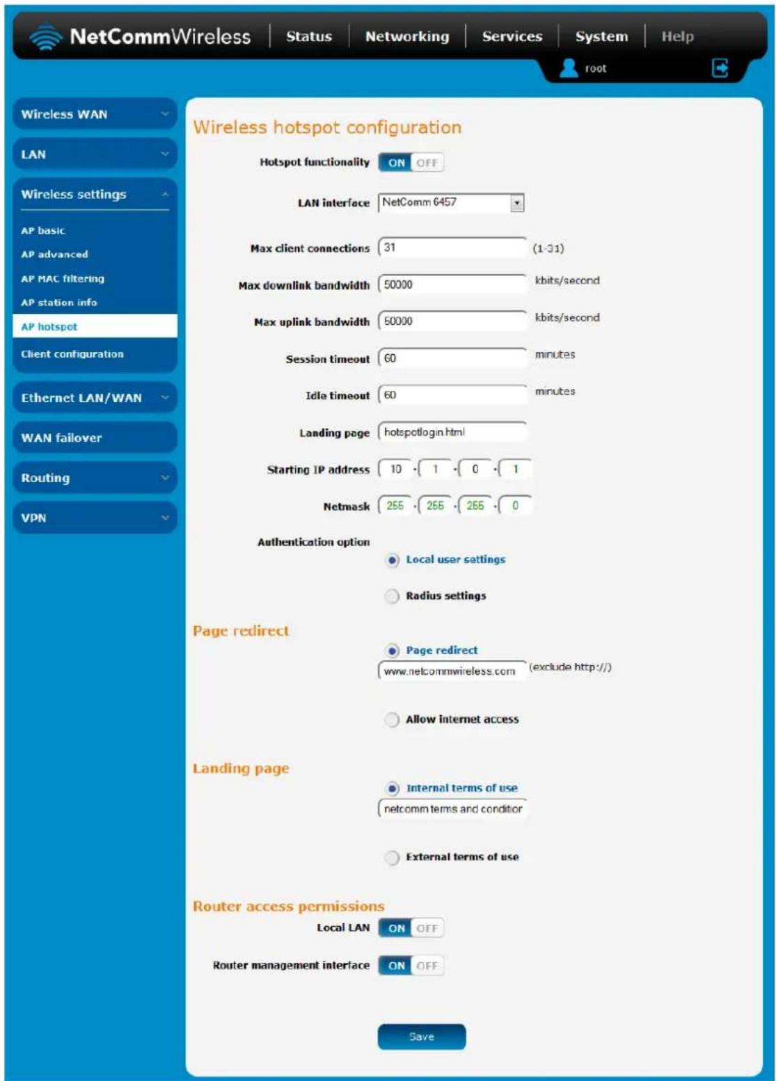
Figure 48 - Wireless hotspot configuration
| ITEM | DESCRIPTION |
| Hotspot functionality | Turns the wireless hotspot feature on or off. |
| LAN interface | Specifies the LAN interface to use for the wireless hotspot. |
| Max client connections | The maximum number of wireless clients permitted to connect to the wireless hotspot. |
| Max downlink bandwidth | The maximum downlink speed in kilobits per second. |
| Max uplink bandwidth | The maximum uplink speed in kilobits per second. |
| Session timeout | The number of minutes that a client may use the WAN connection before being forced to authenticate again. |
| Idle timeout | The number of minutes that a client may be idle before being forced to authenticate again. |
| Starting IP address | The starting IP address for the wireless hotspot network. The starting IP address is assigned to the router and subsequent addresses are assigned to clients as they connect. |
| Netmask | The network mask of the LAN IP range. |
| Authentication option | Selects whether to use the Local user settings or a remote RADIUS server to authenticate users on the wireless hotspot. |
| Radius settings | |
| Radius server 1 | Primary RADIUS Server domain name e.g. radius.netcomm.com |
| Radius server 2 | Backup RADIUS Server domain name e.g. radius.netcomm.com |
| Authentication port | The port used for RADIUS authentication e.g. 1205 |
| SSID | This is usually the SSID of the hotspot and is used during the authentication process. |
| Shared secret | The WPA pre-shared key on the wireless network. |
| Re-enter shared secret | The WPA pre-shared key on the wireless network. |
| Page redirection | |
| Page redirect | Page redirect: redirects the user to a specified website after they have authenticated or agreed to terms of use.Allow internet access: allows internet access upon successful authentication or agreement with terms of use. |
| Landing page | Internal terms of use: Enter the terms of use into the field below. The Terms of Use are displayed as text after the user authenticates or agrees to terms of useNo terms of use: Allows the user internet access immediately after authentication.External terms of use: Enter the address of a page containing the terms of use. |
| Router access permissions | |
| Local LAN | Turning this on allows wireless hotspot clients to access clients on the local LAN and vice versa. |
| Router management interface | Turning this on allows wireless hotspot clients to access the router's management interface. |
Table 16 – Wireless hotspot settings
Client configuration
As a wireless client, the NTC-140W is able to connect to another wireless access point to gain network or internet access. The Client configuration page provides the ability to turn on or off the wireless radio, find nearby access points and configure a connection to an access point.
The NTC-140W may run both Access Point and Client simultaneously, however, since they share the wireless channel, both client and access point must use the same channel.
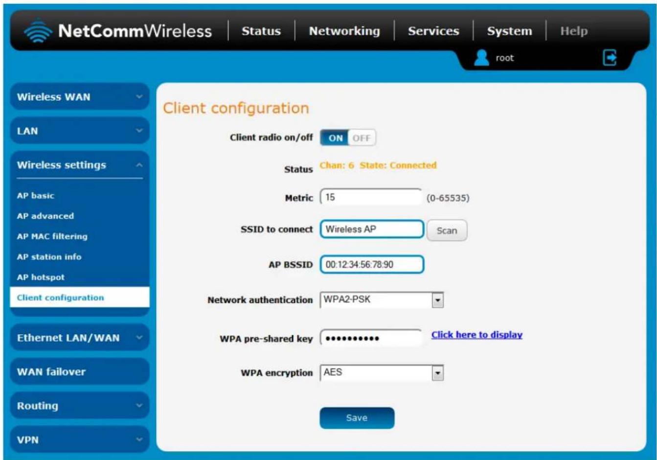
Figure 49 - Wireless settings - Client Configuration
| OPTION | DEFINITION |
| Client radio on/off | Turns the wireless radio on or off. |
| Status | Displays the current channel and connection status of the wireless client. |
| Metric | The metric value is used by the router to prioritise routes. |
| SSID to connect | Enter the SSID of the network you wish to connect to or you may use the Scan button to discover nearby networks. |
| AP BSSID | The BSSID or MAC address of the access point to which you are connecting. |
| Network authentication | The type of authentication in use on the network. |
| WPA pre-shared key | Enter the pre-shared key required to join the wireless network. |
| WPA encryption | Select the type of encryption in use on the network. |
Table 17 - Wireless settings - Client Configuration
Scanning for a network
To find a nearby network to connect to, click the Scan button. A list of discovered networks appears at the bottom of the screen. Click the corresponding Connect button for the network to which you would like to connect.
Access Point List
| No. | SSID | BSSID | Security | Channel | Signal StrengthMode | Wireless Action |
| 1 | 00:04:ed:ef:c1:19 | WPA2PSK/TKIPAES | 1 | 99 | 11b/g/n Connect | |
| 2 | 4c:5e:0c:43:a5:e7 | NONE | 1 | 100 | 11b/g/n Connect | |
| 3 | 6a:04:ed:ef:c1:1a | WPA1PSKWPA2PSK/TKIPAES | 1 | 94 | 11b/g/n Connect | |
| 4 | 00:1f:a4:92:d4:fb | WPA2PSK/AES | 1 | 100 | 11b/g/n Connect |
Figure 50 - Access point list
The network's details are copied across to the Client configuration page. If the wireless network is secured, enter the authentication details, then click the Save button.
Ethernet LAN/WAN
The Ethernet LAN/WAN pages provide configuration options for the two built-in Ethernet ports and any USB-to-Ethernet ports you may connect.
Ethernet group
The Ethernet group page displays the Ethernet interfaces and allows you to configure whether they operate in LAN or WAN mode.
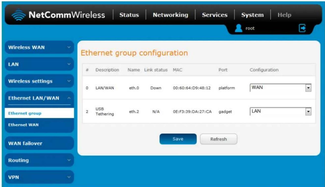
Figure 51 - Ethernet group configuration
| OPTION | DEFINITION |
| # | A number identifying the interface on the router. |
| Description | A description of the type of interface. |
| Name | The name used to identify the interface on the router. |
| Link status | Displays whether the interface is inserted |
| MAC | The MAC address of the interface. |
| Port | The type of port. |
| Configuration | Select whether the port operates as a LAN or WAN port. |
Table 18 - Ethernet group configuration items
Ethernet WAN
The Ethernet WAN page allows you to configure the connection type and metric of the available WAN connections.
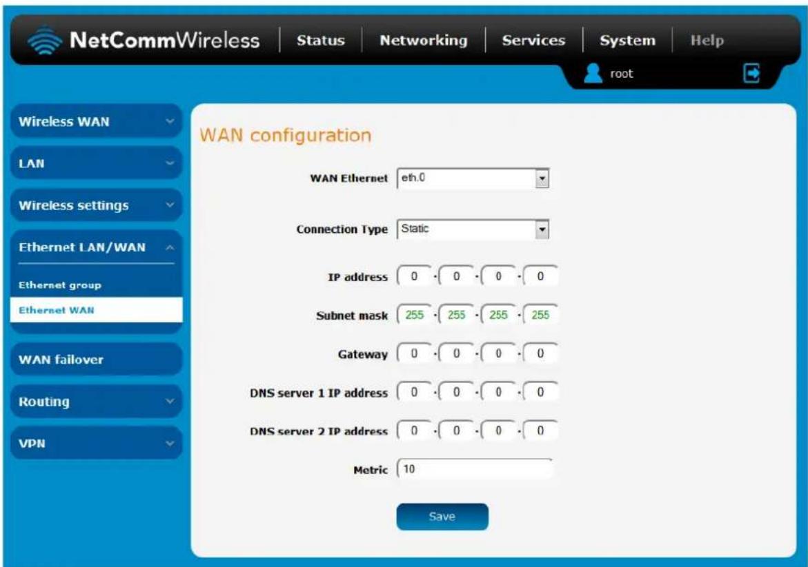
Figure 52 - Ethernet WAN configuration
| OPTION | DEFINITION |
| WAN Ethernet | Use this field to select the WAN interface to configure. |
| Connection Type | Selects whether the WAN interface has static IP settings or DHCP. |
| IP address | The IP address to assign to the selected WAN interface. |
| Subnet mask | The Subnet mask of the IP address above. |
| Gateway | The gateway to assign this WAN interface. |
| DNS server 1 IP address | The first DNS server for the WAN interface. |
| DNS server 2 IP address | The second DNS server for the WAN interface. |
| Metric | The metric value is used to define the priority of the interface. Lower metric values indicate higher priority. |
Table 19 - Ethernet WAN configuration options
WAN failover
The WAN failover page displays a summary of the configured WAN interfaces and their priorities (Metric). Lower metric values determine higher priority. The priority of the interfaces can be adjusted using the up and down arrows in the Priority column. When the interface with the highest priority goes down, the router fails over to the next highest priority interface. The method used to determine whether an interface is "up" or "down" is defined by the Monitor setting. By default, an interface is monitored by its link status.
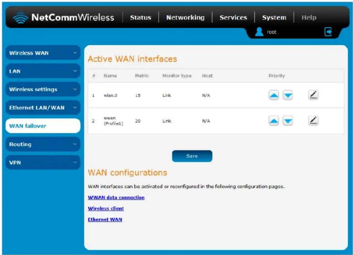
Figure 53 - WAN summary
To edit an interface, select the edit icon for the interface you wish to edit. The Failover configuration page is displayed. When Monitoring method is set to Hardware link the failover is controlled by the physical detection of the link.
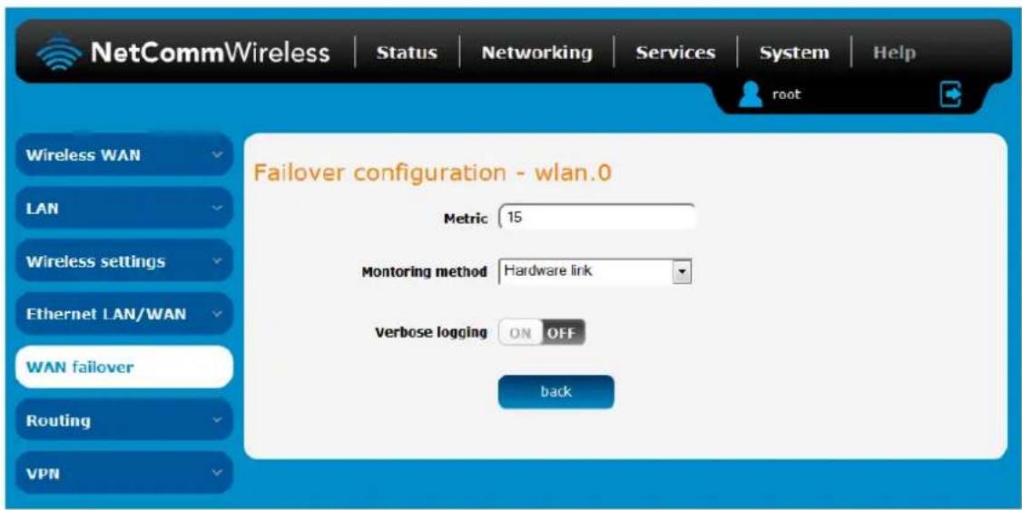
Figure 54 – Fallover configuration – hardware link
| OPTION | DESCRIPTION |
| Priority | The priority (metric) is a numeric value which determines which interface has priority. Lower priority values mean higher priority. |
| Monitoring method | Specifies the means used to determine whether the link is up or down. |
| Verbose logging | When enabled, this logs verbose comments in the system log related to the failover monitoring. |
Table 20 - Failover configuration - Hardware link monitoring
When Monitoring method is set to Ping, the router sends periodic ping requests to the specified addresses to verify the connection is working. This works in a similar manner to the Watchdogs feature but with different ranges on the timers. Please refer to the Watchdogs section of this user guide for a more detailed description of this function.
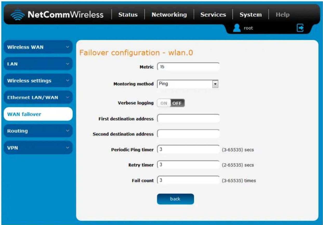
Figure 55 - Failover configuration - ping
| OPTION | DESCRIPTION |
| Priority | The priority (metric) is a numeric value which determines which interface has priority. Lower priority values mean higher priority. |
| Monitoring method | Specifies the means used to determine whether the link is up or down. |
| Verbose logging | When enabled, this logs verbose comments in the system log related to the failover monitoring. |
| First destination address | The first address the router that the router should ping in order to confirm the connection is up. This may be an IP address or a domain name. |
| Second destination address | The second address the router that the router should ping in order to confirm the connection is up. This may be an IP address or a domain name. |
| Periodic Ping timer | The time in seconds between ping attempts. |
| Retry timer | The time in seconds between attempts when a ping failure occurs. |
| Fail count | The number of failed pings that must occur before the monitor moves to the second destination address or fails the connection over to the next interface. |
Table 21 - Failover configuration - Ping monitoring
Routing
Static
Static routing is the alternative to dynamic routing used in more complex network scenarios and is used to facilitate communication between devices on different networks. Static routing involves configuring the routers in your network with all the information necessary to allow the packets to be forwarded to the correct destination. If you change the IP address of one of the devices in the static route, the route will be broken.
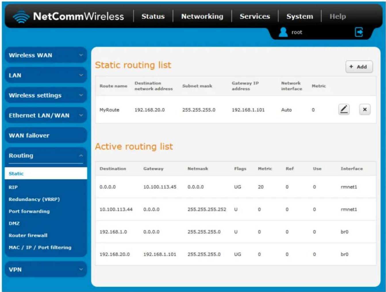
Figure 56 - Static routing list
Some routes are added by default by the router on initialization such as the Ethernet subnet route for routing to a device on the Ethernet subnet.192
Adding Static Routes
To add a new route to the static routing list, click the +Add button. The Static routes page appears.
- In the Route name field, type a name for the route so that it can be identified in the static routing list.
- From the Network interface drop down list, select the interface for which you would like to create a static route.
- In the Destination IP address field, enter the IP address of the destination of the route.
- In the IP subnet mask field, enter the subnet mask of the route.
- In the Gateway IP address field, enter the IP address of the gateway that will facilitate the route.
- In the Metric field enter the metric for the route. The metric value is used by the router to prioritise routes. The lower the value, the higher the priority. To give the route the highest priority, set it to 0.
- Click the Save button to save your settings.
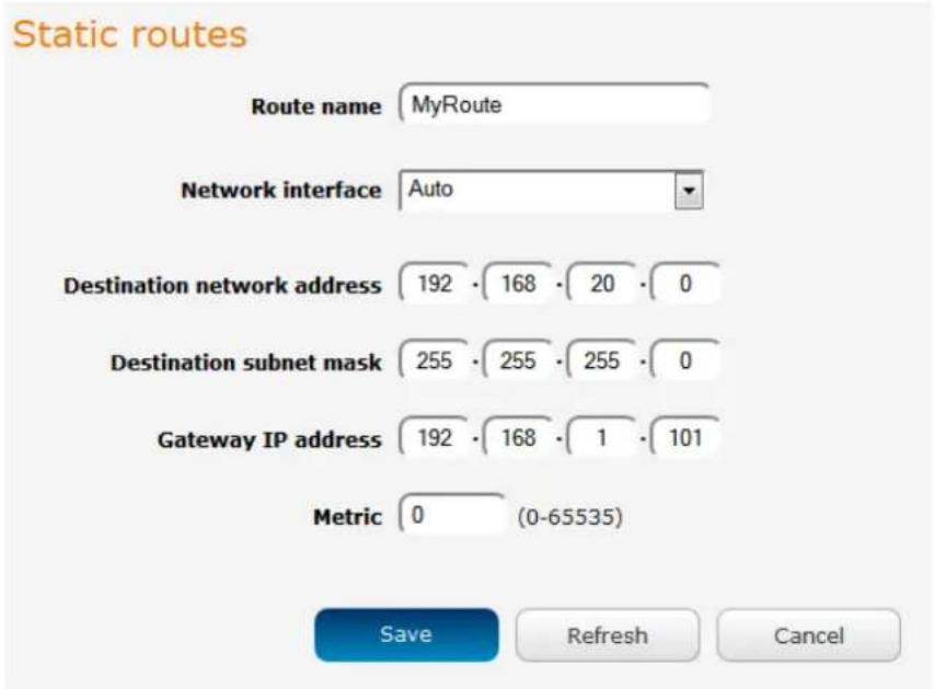
Figure 57 - Adding a static route
Active routing list
Static routes are displayed in the Active routing list.
Active routing list
| Destination | Gateway | Netmask | Flags | Metric | Ref | Use | Interface |
| 0.0.0.0 | 10.102.193.242 | 0.0.0.0 | UG | 20 | 0 | 0 | rmnet1 |
| 10.102.193.240 | 0.0.0.0 | 255.255.255.252 | U | 0 | 0 | 0 | rmnet1 |
| 192.168.1.0 | 0.0.0.0 | 255.255.255.0 | U | 0 | 0 | 0 | br0 |
| 192.168.20.0 | 192.168.1.101 | 255.255.255.0 | UG | 0 | 0 | 0 | br0 |
Figure 58 - Active routing list
Deleting static routes
From the static routing list, click the icon to the right of the entry you wish to delete.
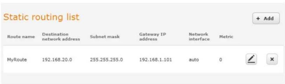
Figure 59 - Deleting a static route
RIP
RIP (Routing Information Protocol) is used for advertising routes to other routers. Thus all the routes in the router's routing table will be advertised to other nearby routers. For example, the route for the router's Ethernet subnet could be advertised to a router on the PPP interface side so that a router on this network will know how to route to a device on the router's Ethernet subnet. Static routes must be added manually according to your requirements. See Adding Static Routes.

Note: Some routers will ignore RIP.
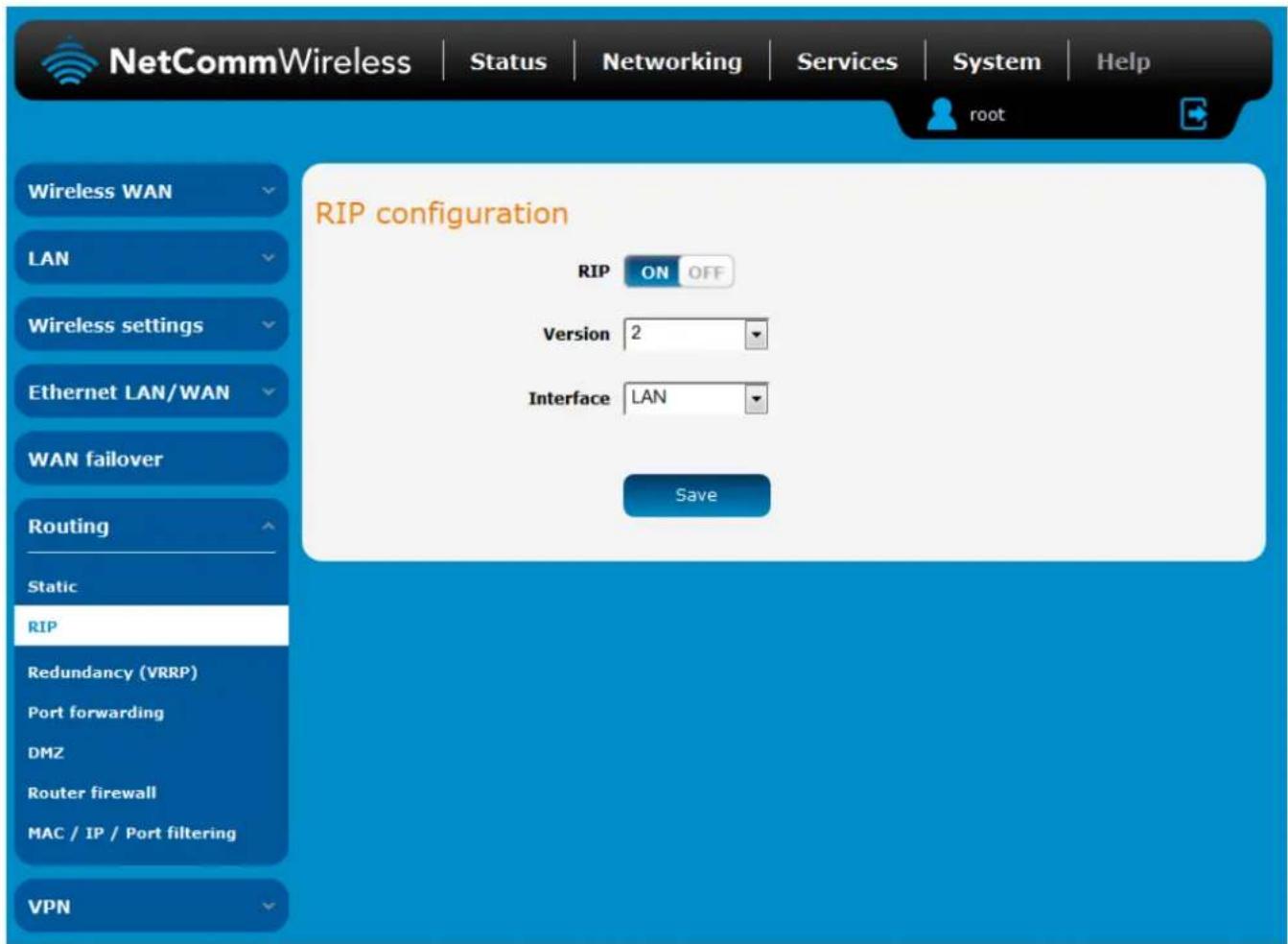
Figure 60 - RIP configuration
To enable Routing Information Protocol (RIP)
- Click the RIP toggle key to switch it to the ON position.
- Using the Version drop down list, select the version of RIP that you would like to use.
- Select the interface for which you want RIP to apply. You can choose the LAN interface, the WWAN interface or BOTH.
- Click the Save button to confirm your settings.
Redundancy (VRRP) configuration
Virtual Router Redundancy Protocol (VRRP) is a non-proprietary redundancy protocol designed to increase the availability of the default gateway servicing hosts on the same subnet. This increased reliability is achieved by advertising a "virtual router" (an abstract representation of master and backup routers acting as a group) as a default gateway to the host(s) instead of one physical router. Two or more physical routers are then configured to stand for the virtual router, with only one doing the actual routing at any given time. If the current physical router that is routing the data on behalf of the virtual router fails, an arrangement is made for another physical router to automatically replace it. The physical router that is currently forwarding data on behalf of the virtual router is called the master router.
Master routers have a priority of 255 and backup router(s) can have a priority between 1 and 254.
A virtual router must use 00-00-5E-00-01-XX as its (MAC) address. The last byte of the address (XX) is the Virtual Router Identifier (VRID), which is different for each virtual router in the network. This address is used by only one physical router at a time, and is the only way that other physical routers can identify the master router within a virtual router.
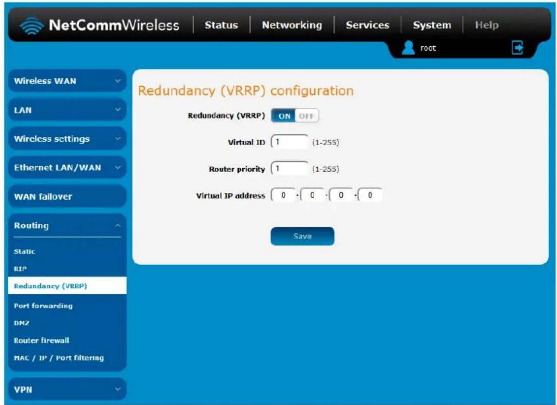
Figure 6.1 - VRRP configuration
To configure VRRP, configure multiple devices as follows and connect them all via an Ethernet network switch to downstream devices.
- Click the Redundancy (VRRP) toggle key to activate VRRP.
- In the Virtual ID field, enter an ID between 1 and 255. This is the VRRP ID which is different for each virtual router on the network.
- In the Router priority field, enter a value for the priority – a higher value is a higher priority.
- The Virtual IP address field is used to specify the VRRP IP address – this is the virtual IP address that both virtual routers share.
- Click the Save button to save the new settings.

Note: Configuring VRRP changes the MAC address of the Ethernet port and therefore if you want to resume with the web configuration you must use the new IP address (VRRP IP) or on a command prompt type:
arp -d
Port Forwarding
The Port forwarding list is used to configure the Network Address Translation (NAT) rules currently in effect on the router.
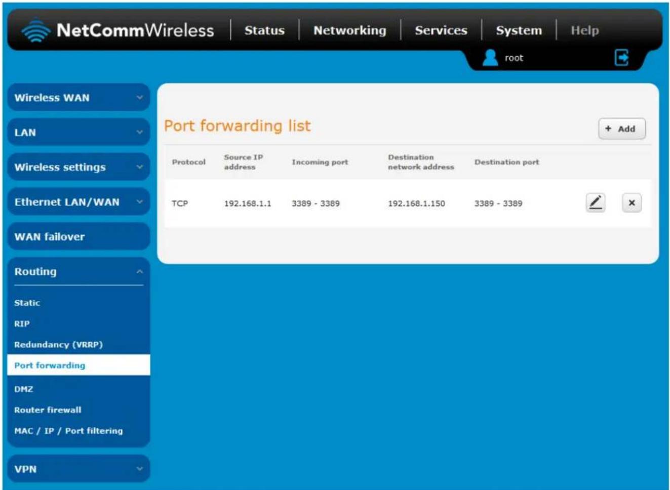
Figure 62 – Port forwarding list
The purpose of the port forwarding feature is to allow mapping of inbound requests to a specific port on the WAN IP address to a device connected on the Ethernet interface.
Adding a port forwarding rule
To create a new port forwarding rule:
- Click the +Add button. The port forwarding settings screen is displayed.
- Use the Protocol drop down list to select the type of protocol you want to use for the rule. The protocols selections available are TCP, UDP and All.
- In the Source IP Address field, enter a "friendly" address that is allowed to access the router or a wildcard IP address (0.0.0.0) that allows all IP addresses to access the router.
- The Source Port Range (From) and (To) fields are used to specify the port(s) on the source side that are to be forwarded. This allows you to send a range of consecutive port numbers by entering the first in the range in the (From) field and the last in the range in the (To) field. To forward a single port, enter the port in the (From) field and repeat it in the (To) field.
- In the Destination network address field, enter the IP address of the client to which the traffic should be forwarded.
- The Destination Port Range (From) and (To) fields are used to specify the port(s) on the destination side that are to be forwarded. If the Source port range specifies a single port then the destination port may be configured to any port. If the Source port range specifies a range of port numbers then the Destination port range must be the same as the Source port range.
- Click the Save button to confirm your settings.
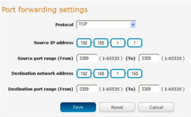
Figure 63 - Port forwarding settings
To delete a port forwarding rule, click the ✗ button on the Port forwarding list for the corresponding rule that you would like to delete.
DMZ
The Demilitarized Zone (DMZ) allows you to configure all incoming traffic on all protocols to be forwarded to a selected device behind the router. This feature can be used to avoid complex port forwarding rules, but it exposes the device to untrusted networks as there is no filtering of what traffic is allowed and what is denied.
The DMZ configuration page is used to specify the IP Address of the device to use as the DMZ host.
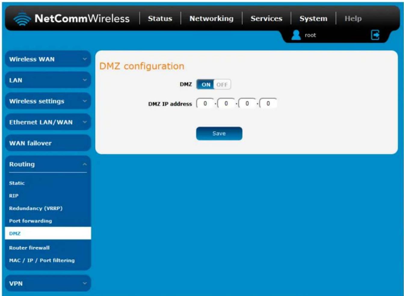
Figure 64 - DMZ configuration
- Click the DMZ toggle key to turn the DMZ function ON.
- Enter the IP Address of the device to be the DMZ host into the DMZ IP Address field.
- Click the Save button to save your settings.
Router firewall
The Router firewall page is used to enable or disable the in-built firewall on the router. When enabled, the firewall performs stateful packet inspection on inbound traffic from the wireless WAN and blocks all unknown services, that is, all services not listed on the Services configuration page of the router.
With respect to the other Routing options on the Networking page, the firewall takes a low priority. The priority of the firewall can be described as:
DMZ > MAC/IP/Port filtering rules > MAC/IP/Port filtering default rule > Router firewall rules
In other words, the firewall is of the lowest priority when compared to other manual routing configurations. Therefore, a MAC/IP/Port filtering rule takes priority in the event that there is a conflict of rules. When DMZ is enabled, MAC/IP/Port filtering rules and the router firewall are ignored but the router will still honour the configuration of the Remote router access control settings listed under Administration Settings.
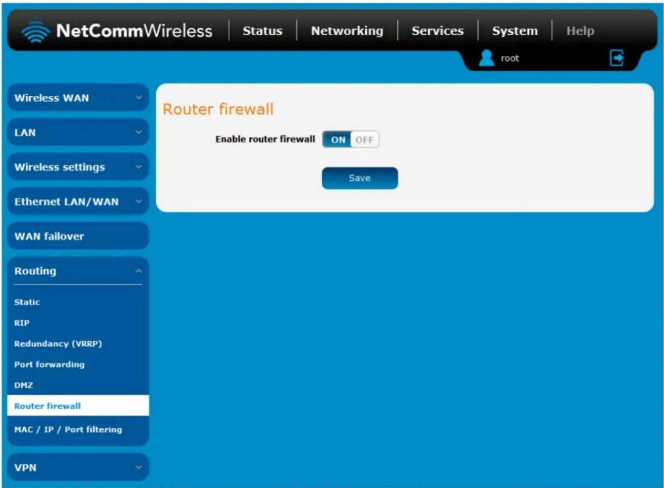
Figure 65 - Router firewall toggle key
MAC / IP / Port filtering
The MAC/IP/Port filter feature allows you apply a policy to the traffic that passes through the router, both inbound and outbound, so that network access can be controlled. When the filter is enabled with a default rule of "Accepted", all connections will be allowed except those listed in the "Current MAC / IP / Port filtering rules in effect" list. Conversely, when the default rule is set to "Dropped", all connections are denied except for those listed in the filtering rules list.
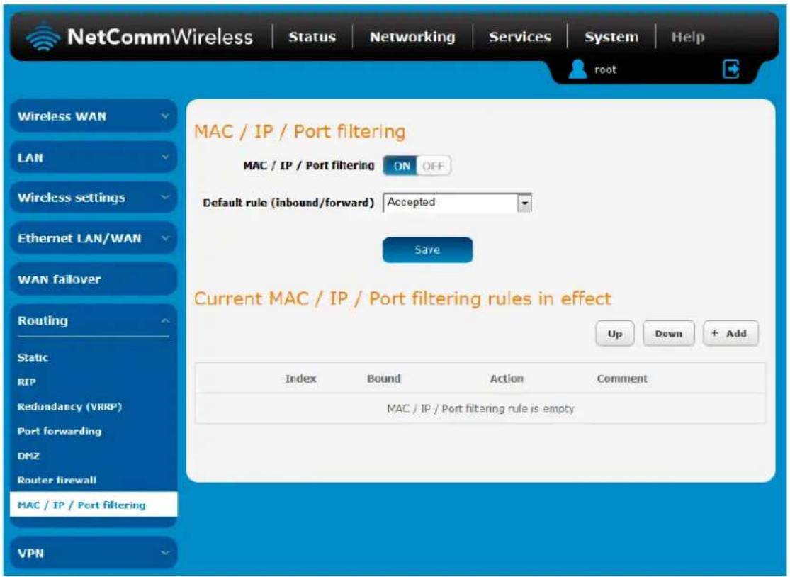
Figure 66 - MAC / IP / Port filtering

Note: When enabling MAC/IP/Port filtering and setting the default rule to "Dropped", you should ensure that you have first added a filtering rule which allows at least one known MAC/IP to access the router, otherwise you will not be able to access the user interface of the router without resetting the router to factory default settings.
Creating a MAC / IP / Port filtering rule
To create a filtering rule:
- Click the MAC / IP / Port filtering toggle key to switch it to the ON position.
- Using the Default rule (inbound/forward) drop down list, select the default action for the router to take when traffic reaches it. By default, this is configured to Accepted. If you change this to Dropped, you should first configure a filter rule that allows at least one device access to the router, otherwise you will effectively be locked out of the router.
- Click the Save button to confirm the default rule.
- In the Current MAC / IP / Port filtering rules in system section, click the +Add button.
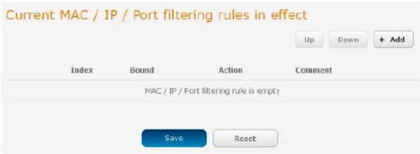
Figure 67 - Current MAC / IP/ Port filtering rules in effect
- Enter the details of the rule in the section that is displayed and click the Save button.
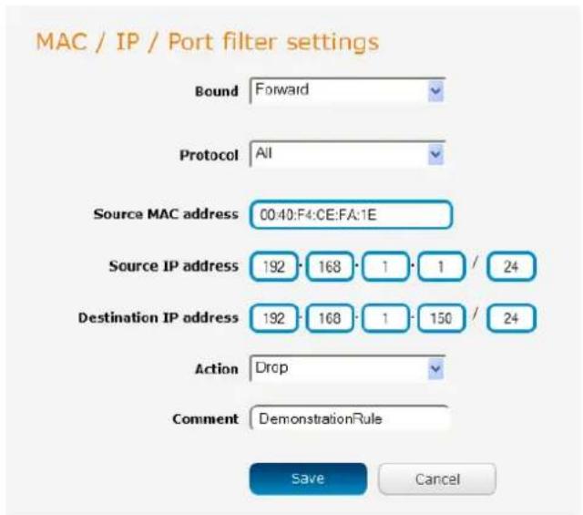
Figure 68 - MAC / IP / Port filtering settings
| OPTION | DESCRIPTION |
| Bound | Use the drop down list to select the direction of the traffic for which you want to apply to the rule. Inbound refers to all traffic that is entering the router including data entering from the WAN and the LAN. Outbound refers to all traffic exiting the router including traffic leaving in the direction of the WAN and traffic leaving in the direction of the LAN. Forward specifies traffic that enters on the LAN or WAN side and is forwarded to the opposite end. |
| Protocol | Use the drop down list to select the protocol for the rule. You can have the rule apply to All protocols, TCP, UDP, UDP/TCP or ICMP. |
| Source MAC Address | Enter the MAC address in six groups of two hexadecimal digits separated by colons (:). e.g. 00:40:F4:CE:FA:1E |
| Source IP Address | Enter the IPv4 address that the traffic originates from and the subnet mask using CIDR notation. |
| Destination IP Address | Enter the IPv4 address that the traffic is destined for and the subnet mask using CIDR notation. |
| Action | Select the action to take for traffic which meets the above criteria. You can choose to Accept or Drop packets. When the default rule is set to Accept, you cannot create a rule with an Accept action since the rule is redundant. Likewise, if the default rule is set to Dropped you cannot create a rule with a Drop action. |
| Comment | [Optional] Use this field to enter a comment as a meaningful description of the rule. |
Table 22 - Current MAC/IP/Port filtering rules in effect
- The new rule is displayed in the filtering rules list. You can edit the rule by clicking the Edit button or delete the rule by clicking the button.
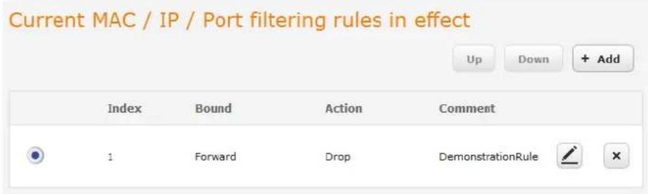
Figure 69 - Completed filtering rule
VPN
A Virtual Private Network (VPN) is a tunnel providing a private link between two networks or devices over a public network. Data to be sent via a VPN needs to be encapsulated and as such is generally not visible to the public network.
The advantages of a VPN connection include:
Data Protection
Access Control
Data Origin Authentication
Data Integrity
Each VPN connection has different configuration requirements. The following pages detail the configuration options available for the different VPN connection types.

Note: The following descriptions are an overview of the various VPN options available. More detailed instructions are available in separate whitepapers on the NetComm Wireless website.
IPSec
IPSec operates on Layer 3 of the OSI model and as such can protect higher layered protocols. IPSec is used for both site to site VPN and Remote Access VPN. The NTC-140W Series router supports IPsec end points and can be configured with Site to Site VPN tunnels with third party VPN routers.
Configuring an IPSec VPN
From the menu at the top of the screen, click Networking and under the VPN section, click IPSec. A list of configured IPSec VPN connections is displayed.
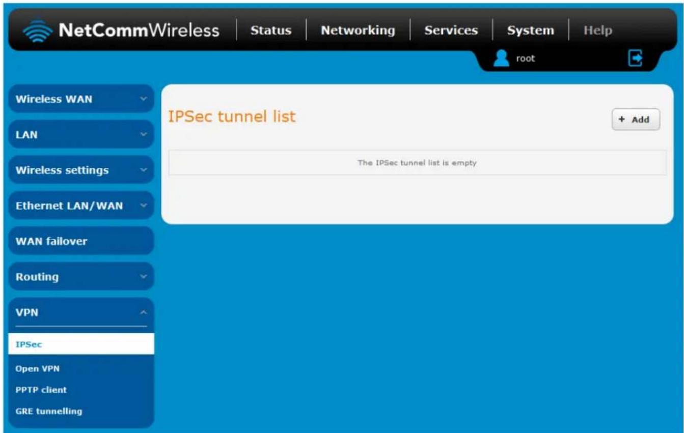
Figure 70 - IPSec VPN List
Click the +Add button to begin configuring an IPSec VPN connection.
IPSec profile edit
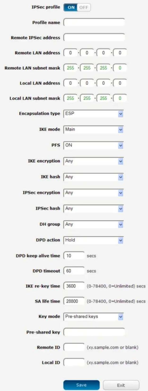
Figure 71 – IPSec profile edit
The following table describes each of the fields of the IPSec VPN Connection Settings page.
| ITEM | DEFINITION |
| IPSec profile | Enables or disables the VPN profile. |
| Profile name | A name used to identify the VPN connection profile. |
| Remote IPSec address | The IP address or domain name of the IPSec server. |
| Remote LAN address | Enter the IP address of the remote network for use on the VPN connection. |
| Remote LAN subnet mask | Enter the subnet mask in use on the remote network. |
| Local LAN address | Enter the IP address of the local network for use on the VPN connection. |
| Local LAN subnet mask | Enter the subnet mask in use on the local network. |
| Encapsulation type | Select the encapsulation protocol to use with the VPN connection. You can choose ESP, AH or Any. |
| IKE mode | Select the IKE mode to use with the VPN connection. You can choose Main, Aggressive or Any. |
| PFS | Choose whether Perfect Forward Secrecy is ON or OFF for the VPN connection. |
| IKE encryption | Select the cipher type to use for the Internet Key Exchange. |
| IKE hash | Select the IKE Hash type to use for the VPN connection. The hash is used for authentication of packets for the key exchange. |
| IPSec encryption | Select the IPSec encryption type to use with the VPN connection. |
| IPSec hash | Select the IPSec hash type to use for the VPN connection. The hash is used for authentication of packets for the VPN connection. |
| DH group | Select the desired Diffie-Hellman group to use. Higher groups are more secure but also require longer to generate a key. |
| DPD action | Select the desired Dead Peer Detection action. This is the action to take when a dead Internet Key Exchange Peer is detected. |
| DPD keep alive time | Enter the time in seconds for the interval between Dead Peer Detection keep alive messages. |
| DPD timeout | Enter the time in seconds of no response from a peer before Dead Peer Detection times out. |
| IKE re-key time | Enter the time in seconds between changes of the encryption key. To disable changing the key, set this to 0. |
| SA life time | Enter the time in seconds for the security association lifetime. |
| Key mode | Select the type of key mode in use for the VPN connection. You can select from:Pre Shared KeyRSA keysCertificates |
| Pre-shared key | The pre-shared key is the key that peers used to authenticate each other for Internet Key Exchange. |
| Remote ID | Specifies the domain name of the remote network. |
| Local ID | Specifies the domain name of the local network. |
| Update Time | Displays the last time the key was updated. |
| Local RSA Key Upload | Select the RSA key file for the local router here by clicking the Browse button. |
| Remote RSA Key Upload | Select the RSA key file for the remote router here by clicking the Browse button. |
| Private key Passphrase | The Private key passphrase of the router is the passphrase used when generating the router's private key using OpenSSL CA. |
| Key / Certificate | Select the type of key or certificate to use for authentication. You can select Local private key, Local public certificate, Remote public certificate, CA certificate, CRL certificate. |
| IPSec Certificate Upload | Select the IPSec certificate to upload by clicking the Browse button. |
Table 23 - IPSec Configuration Items
OpenVPN
OpenVPN is an open source virtual private network (VPN) program for creating point-to-point or server-to-multi-client encrypted tunnels between host computers. It can traverse network address translation (NAT) and firewalls and allows authentication by certificate, pre-shared key or username and password. OpenVPN works well through proxy servers and can run over TCP and UDP transports. Support for OpenVPN is available on several operating systems, including Windows, Linux, Mac OS, Solaris, OpenBSD, FreeBSD, NetBSD and QNX.
Configuring an Open VPN server
From the menu at the top of the screen, click Networking and from the VPN section on the left, click OpenVPN. A list of configured OpenVPN VPN connections is displayed.
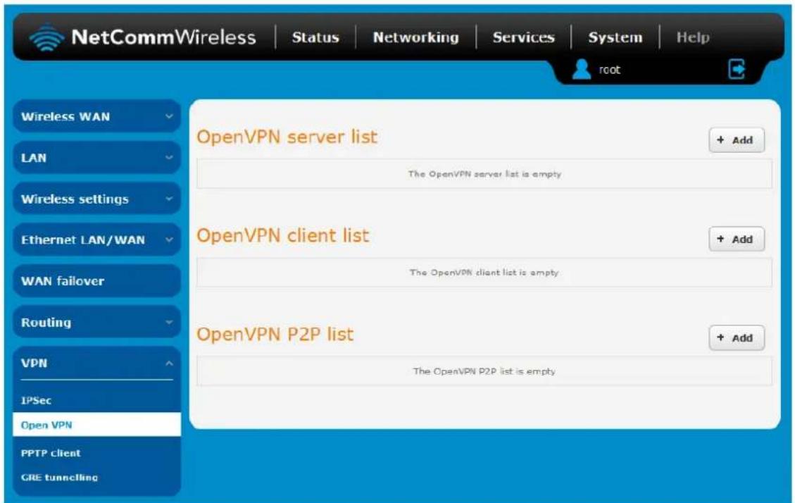
Figure 72 - OpenVPN VPN List
Click the +Add button for the type of OpenVPN server/client you would like to configure.
OpenVPN Server
To configure an OpenVPN Server:
- Click the OpenVPN profile toggle key to switch it to the ON position.
- Type a name for the OpenVPN server profile you are creating.
- Select OpenVPN connection type (TUN/TAP). Default is TUN.
- Use the Server port field to select a port number and then use the drop down list to select a packet type to use for your OpenVPN Server. The default OpenVPN port is 1194 and default packet type is UDP.
- In the VPN network address and VPN network subnet mask fields, enter the IP address and network subnet mask to assign to your VPN. This is ideally an internal IP address which differs from your existing address scheme.
- Next to Diffie-Hellman parameters, select appropriate encryption key size then click the Generate DH button. This will create an encryption key to secure your OpenVPN connection. Default key size is (1024) bit.
- Under Server Certificates, enter the required details. All fields must be completed. The Country field must consist of two characters only. When the details have been entered, click the Generate CA certificate button to generate the Certificate Authority (CA) certificate based on this information.
- Under the Server certificates section, select the Authentication type that you would like to use for the OpenVPN Server.

Note: The Diffie-Hellman parameters can take up to 10 minutes to generate. Please be patient.
Certificate Authentication
In the Certificate Management section, enter the required details to create a client certificate. All fields are required. When you have finished entering the details, click the Generate button.
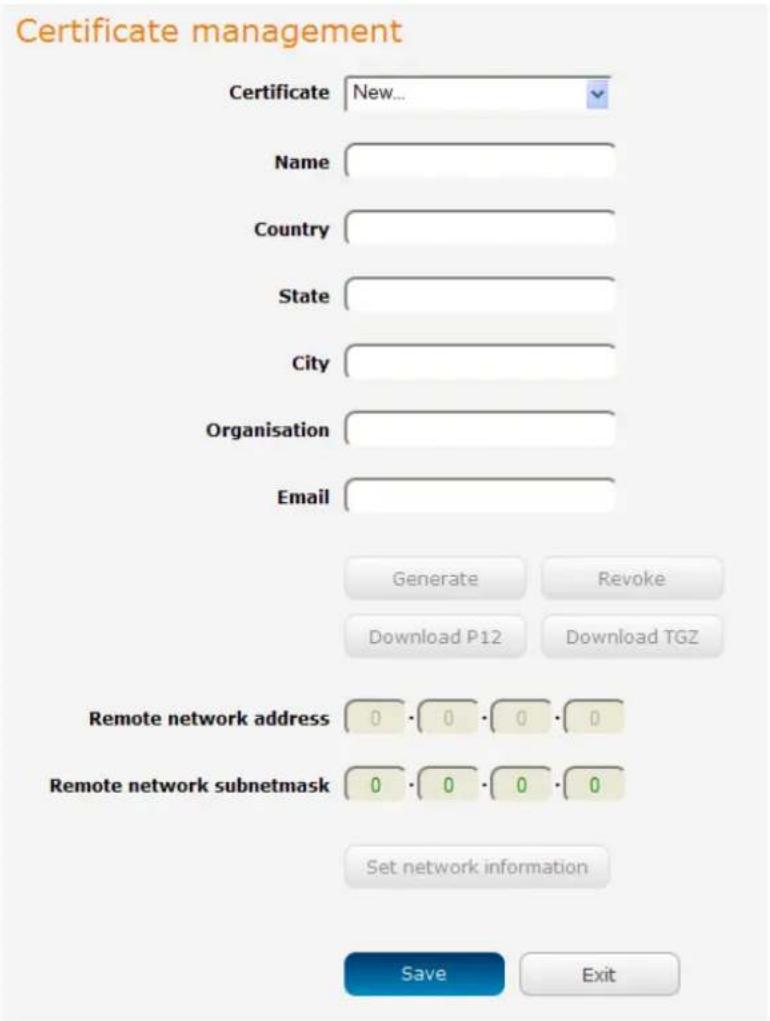
Figure 73 - OpenVPN server configuration – Certificate management
When it is done, you can click the Download P12 button or the Download TGZ button to save the certificate file depending on which format you would like. If for some reason the integrity of your network has been compromised, you can return to this screen and use the Certificate drop down list to select the certificate and then press the Revoke button to disable it.
Optional: To inform the OpenVPN server of the network address scheme of the currently selected certificate, enter the network address and network subnet mask in the respective fields and click the Set network information button. If you do not enter the remote subnet here, any packet requests from the server to the client will not be received by the client network because it is not aware of the remote client's subnet.
OpenVPN server edit
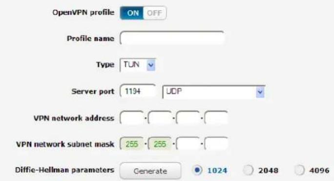
Server certificates
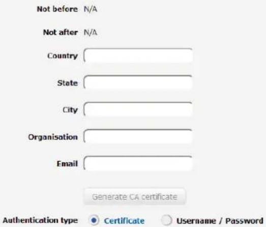
Certificate management
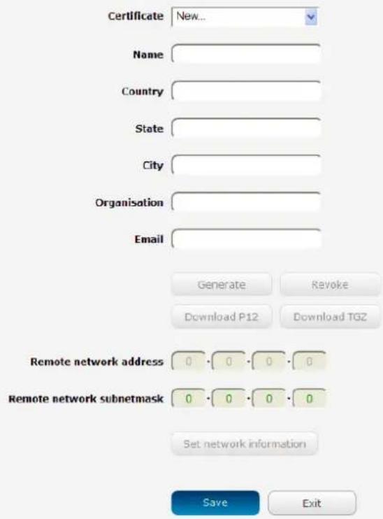
Figure 74 – OpenVPN server profile settings
Username / Password Authentication
In the Username/Password section, enter the username and password you would like to use for authentication on the OpenVPN Server. Click the Download CA certificate or Download CA TGZ depending on file format button to save the ca.crt file. This file will need to be provided to the client.

Note: If you wish to have more than one client connect to this OpenVPN server, you must use Certificate authentication mode as Username/Password only allows for a single client connection.
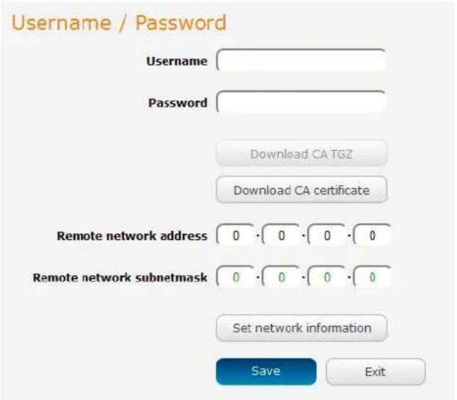
Figure 75 - Open VPN Server - Username / Password section
Optional: To inform the OpenVPN server of the network address scheme of the currently selected certificate, enter the network address and network subnet mask in the respective fields and click the Set Network Information button. If you do not enter the remote subnet here, any packet requests from the server to the client will not be received by the client network because it is not aware of the remote client's subnet.
When you have finished entering all the required information, click Save to finish configuring the OpenVPN server.
Configuring an OpenVPN Client
- Click the OpenVPN profile toggle key to switch it to the ON position.
- In the Profile name field, type a name for the OpenVPN client profile you are creating.
- In the Server IP address field, type the WAN IP address /host domain name of the OpenVPN server.
- Select OpenVPN connection type (TUN/TAP). Default is TUN.
- Use the Server port field to select a port number and then use the drop down list to select a packet type to use for the OpenVPN server. The default OpenVPN port is 1194 and default packet type is UDP.
- If the Default gateway option is applied on the OpenVPN client page, the OpenVPN server will enable connections to be made to other client networks connected to it. If it is not selected, the OpenVPN connection allows for secure communication links between this router and the remote OpenVPN server only.
- Use the Authentication type options to select the Authentication type that you would like to use for the OpenVPN client.
Certificate Authentication
In the Certificate upload section at the bottom of the screen, click the Browse button and locate the certificate file you downloaded when you configured the OpenVPN server. When it has been selected, click the Upload button to send it to the router.

Figure 76 - OpenVPN client - Certificate upload
Username / Password Authentication
Enter the username and password to authenticate with the OpenVPN server.
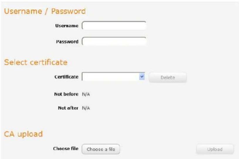
Figure 77 - OpenVPN Client - Username/Password section
Use the Browse button to locate the CA certificate file you saved from the OpenVPN Server and then press the Upload button to send it to the router.
Click the Save button to complete the OpenVPN Client configuration.
Configuring an OpenVPN P2P Connection
To configure an OpenVPN peer-to-peer connection:
- Set the OpenVPN profile toggle key to switch it to the ON position.
- In the Profile name field, type a name for the OpenVPN P2P profile you are creating.
- On the router designated as the server, leave the Server IP address field empty. On the router designated as the client, enter the WAN IP address/host domain name of the server.
OpenVPN peer edit
OpenVPN profile
ON
OFF
Profile name


Server IP address


(leave empty if it's a peer-to-peer server)
Server port
1194
m = 311
UDP

Local IP address


Remote IP address


Remote network
Address


Subnet mask


Server secret key
Update time
N/A
。
Generate
Download
Client secret key
Update time
N/A
1
Delete
Client secret key upload
Choose a file
Save
Exit
Upload
Figure 78 - Open VPN P2P mode settings
- Use the Server port field to select a port number and then use the drop down list to select a packet type to use for the OpenVPN server. The default OpenVPN port is 1194 and default packet type is UDP.
- In the Local IP Address and Remote IP Address fields, enter the respective local and remote IP addresses to use for the OpenVPN tunnel. The slave should have the reverse settings of the master.
- Under the Remote network section, enter the network Address and network Subnet mask. The Network Address and Network Mask fields inform the Master node of the LAN address scheme of the slave.
- Press the Generate button to create a secret key to be shared with the slave. When the timestamp appears, you can click the Download button to save the file to exchange with the other router.
- When you have saved the secret key file on each router, use the Browse button to locate the secret key file for the master and then press the Upload button to send it to the slave. Perform the same for the other router, uploading the slave's secret key file to master.
- When they are uploaded click the Save button to complete the peer-to-peer OpenVPN configuration.
PPTP-Client
The Point-to-Point Tunnelling Protocol (PPTP) is a method for implementing virtual private networks using a TCP and GRE tunnel to encapsulate PPP packets. PPTP operates on Layer 2 of the OSI model and is included on Windows computers.
Configuring the PPTP Client
To configure the PPTP client:
- From the menu bar at the top of the screen, click Networking and then from the VPN section on the left side of the screen, click PPTP client. The PPTP client list is displayed.
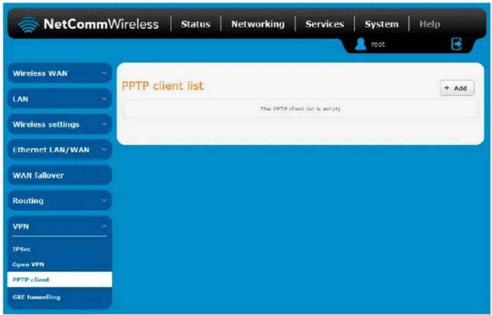
Figure 79 - PPTP client list
- Click the +Add button to begin configuring a new PPTP client profile. The PPTP client edit screen is displayed.
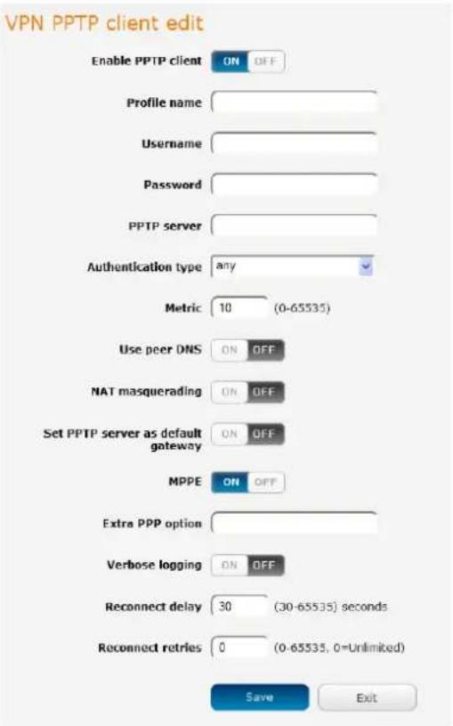
Figure 80 - VPN PPTP client edit
- Click the Enable PPTP client toggle key to switch it to the ON position.
- In the Profile name list, enter a profile name for the tunnel. This may be anything you like and is used to identify the tunnel on the router.
- Use the Username and Password fields to enter the username and password for the PPTP account.
- In the PPTP server address field, enter the IP address /host domain name of the PPTP server.
- From the Authentication type drop down list, select the Authentication type used on the server. If you do not know the authentication method used, select any and the router will attempt to determine the correct authentication type for you. There are 5 authentication types you can choose from:
CHAP – uses a three way handshake to authenticate the identity of a client.
MS-CHAP v1 – This is the Microsoft implementation of the Challenge Handshake Authentication Protocol for which support was dropped in Windows® Vista.
MS-CHAP v2 - This is the Microsoft implementation of the Challenge Handshake Authentication Protocol which was introduced in Windows® NT 4.0 and is still supported today.
PAP – The Password Authentication Protocol uses a password as a means of authentication and as such, is commonly supported. PAP is not recommended because it transmits passwords unencrypted and is not secure.
EAP – Extensible Authentication Protocol. An Authentication protocol commonly used in wireless networks.
-
The metric value helps the router to prioritise routes and must be a number between 0 and 65535. The default value is 30 and should not be modified unless you are aware of the effect your changes will have.
-
The Use peer DNS option allows you to select whether the remote clients will use the Domain Name Server of the PPTP server. Click the toggle key to set this to ON or OFF as required.
-
NAT masquerading allows the router to modify the packets sent and received to inform remote computers on the internet that packets originating from a machine behind the router actually originated from the WAN IP address of the router's internal NAT IP address. Click the toggle key to switch this to the ON position if you want to use this feature.
-
Set default route to PPTP sets all outbound data packets to go out through the PPTP tunnel. Click the toggle key to switch this to the ON position if you want to use this feature.
-
The Verbose logging option sets the router to output detailed logs regarding the PPTP connection in the System Log section of the router interface.
-
The Reconnect delay is the time in seconds that the router will wait before attempting to connect to the PPTP server in the event that the connection is broken. The minimum time to wait is 30 seconds so as to not flood the PPTP server with connection requests, while the maximum time to wait is 65335 seconds.
-
The Reconnect retries is the number of connection attempts that the router will make in the event that the PPTP connection goes down. If set to 0, the router will retry the connection indefinitely, otherwise the maximum number of times to retry cannot be greater than 65335.
-
Click the Save button to save the changes. The VPN will attempt to connect after your click Save. Click the Status button at the top left of the interface to return to the status window and monitor the VPN's connection state.
GRE tunnelling
The Generic Route Encapsulation (GRE) protocol is used in addition to Point-to-Point Tunnelling Protocol (PPTP) to create VPNs (virtual private networks) between clients and servers or between clients only. Once a PPTP control session establishes the VPN tunnel GRE is used to securely encapsulate the data or payload.
Configuring GRE tunnelling
To configure GRE tunnelling:
- From the menu bar at the top of the screen, click Networking and then from the VPN section on the left side of the screen, click GRE. The GRE client list is displayed.
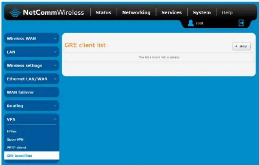
Figure 81 - GRE client list
- Click the +Add button to begin configuring a new GRE tunnelling client profile. The GRE Client Edit screen is displayed.
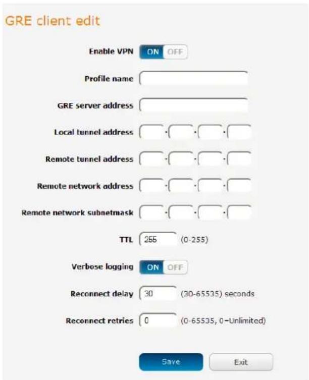
Figure 82 – GRE client edit
- Click the Enable GRE Tunnel toggle key to switch it to the ON position.
- In the Profile name, enter a profile name for the tunnel. This may be anything you like and is used to identify the tunnel on the router.
- In the GRE server address field, enter the IP address or domain name of the GRE server.
- In the Local tunnel address field, enter the IP address you want to assign the tunnel locally.
- In the Remote tunnel address field, enter the IP address you want to assign to the remote tunnel.
- In the Remote network address field, enter the IP address scheme of the remote network.
-
In the Remote network subnetmask field, enter the subnet mask of the remote network.
-
The TTL (Time To Live) field is an 8-bit field used to remove an undeliverable data packet from a network to avoid unnecessary network traffic across the internet. The default value of 255 is the upper limit on the time that an IP datagram can exist. The value is reduced by at least one for each hop the data packet takes to the next router on the route to the datagram's destination. If the TTL field reaches zero before the datagram arrives at its destination the data packet is discarded and an error message is sent back to the sender.
-
The Verbose logging option sets the router to output detailed logs regarding the GRE tunnel in the System Log section of the router interface.
-
The Reconnect delay is the time in seconds that the router will wait before attempting to connect to the GRE server in the event that the connection is broken. The minimum time to wait is 30 seconds so as to not flood the GRE server with connection requests, while the maximum time to wait is 65335 seconds.
-
The Reconnect retries is the number of connection attempts that the router will make in the event that the GRE connection goes down. If set to 0, the router will retry the connection indefinitely, otherwise the maximum number of times to retry cannot be greater than 65335.
-
Click the Save button to save the changes. The VPN will attempt to connect after your click Save. Click the Status button at the top left of the interface to return to the status window and monitor the VPN's connection state.
Services
Dynamic DNS
The DDNS page is used to configure the Dynamic DNS feature of the router. A number of Dynamic DNS hosts are available from which to select.
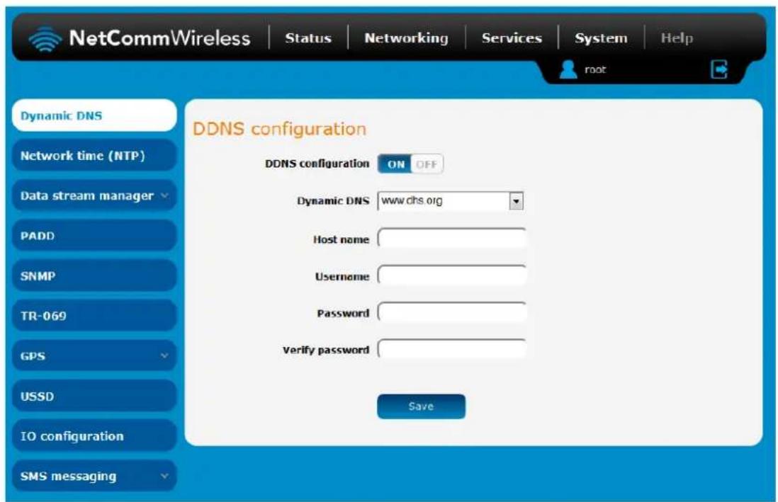
Figure 83 - Dynamic DNS settings
Dynamic DNS provides a method for the router to update an external name server with the current WAN IP address.
To configure dynamic DNS:
- Click the DDNS configuration toggle key to switch it to the ON position.
- From the Dynamic DNS drop down list, select the Dynamic DNS service that you wish to use. The available DDNS services available are:
www.dhs.org
www.dyndns.org
www.dyns.cx
www.easydns.com
www.justlinux.com
www.ods.org
www.tzo.com
www.zoneedit.com
- Enter your hostname in 'Host name' field.
- In the Username and Password fields, enter the logon credentials for your DDNS account. Enter the password for the account again in the Verify password field.
- Click the Save button to save the DDNS configuration settings.
Network time (NTP)
The NTP (Network Time Protocol) settings page allows you to configure the NTC-140W Series router to synchronize its internal clock with a global Internet Time server and specify the time zone for the location of the router. This provides an accurate timekeeping function for features such as System Log entries and Firewall settings where the current system time is displayed and recorded.
Any NTP server available publicly on the internet may be used. The default NTP server is 0.netcomm.pool.ntp.org.
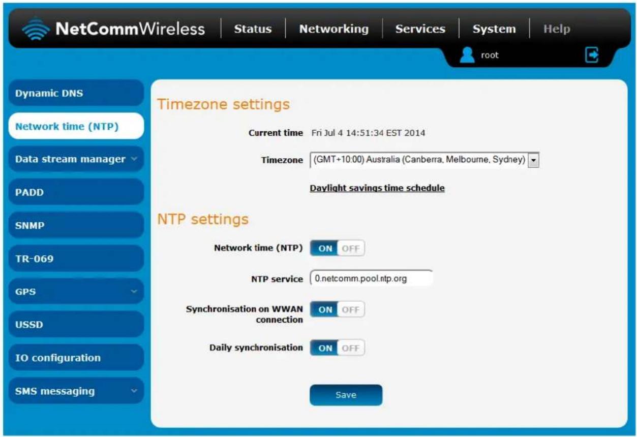
Figure 84 - NTP settings
Configuring Timezone settings
To configure time zone settings:
- The Current time field shows the time and date configured on the router. If this is not accurate, use the Time zone drop down list to select the correct time zone for the router. If the selected zone observes daylight savings time, a Daylight savings time schedule link appears below the drop down list. Click the link to see the start and end times for daylight savings.
- When you have selected the correct time zone, click the Save button to save the settings.
Configuring NTP settings
To configure NTP settings:
- Click the Network time (NTP) toggle key to switch it to the ON position.
- In the NTP service field, enter the address of the NTP server you wish to use.
- The Synchronization on WWAN connection toggle key enables or disables the router from performing a synchronization of the time each time a mobile broadband connection is established.
- The Daily synchronisation toggle key enables or disables the router from performing a synchronization of the time each day.
- When you have finished configuring NTP settings, click the Save button to save the settings.
Data stream manager
The data stream manager provides you with the ability to create mappings between two endpoints on the router. These endpoints may be physical or virtual, for example, a serial port connected to the router's USB port could be configured as an endpoint or you could configure a TCP Server as an endpoint. You can then configure a virtual data tunnel or "stream" between the endpoints.
The data stream manager provides a wide range of possibilities and expands upon simple PAD functionality to include the forwarding and translation of data between any of the endpoints. For example, you could send the GPS data from the built-in module to a TCP server running on the router. In each case, the logical flow of the stream is from Endpoint A to Endpoint B.
Customers interested in developing their own applications to create custom endpoints and streams can contact NetComm Wireless about our Software Development Kit.
Endpoints
The first thing to be done in order to create a data stream is to define the endpoints. There are 6 types of endpoint that may be configured:
Serial port (generic)
TCP Server
TCP Client
UDP Server
UDP Client
GPS Data (for devices with GPS receiver)
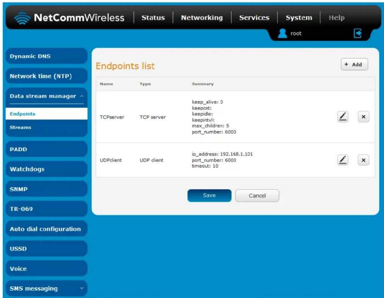
Figure 85 - Endpoints list
To create an endpoint:
- Click the +Add button on the right side of the page. A pop-up window appears.
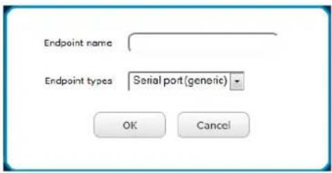
Figure 86 - Creating an endpoint
- In the Endpoint name field, type a name for this endpoint. The name can contain alphanumeric characters only i.e. A-Z, a-z, 0-9.
- Use the Endpoint types drop down list to select the type of endpoint to configure.
Serial port (generic): When a USB to Serial cable is used, this creates a generic serial port as an endpoint defaulting to the commonly used settings as shown below.
Serial port (generic) endpoint (Serial)
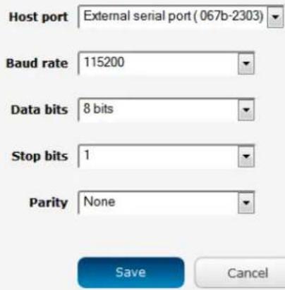
Figure 87 - Serial port (generic) endpoint configuration
TCP server: This creates a TCP server endpoint with the following options available.
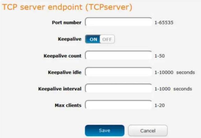
bar
| Metric | Value | | ------------------ | --------- | | Port number | 1-65535 | | Keepalive ON | ON | | Keepalive count | 1-50 | | Keepalive idle | 1-10000 seconds | | Keepalive interval | 1-1000 seconds | | Max clients | 1-20 |Figure 88 - TCP server endpoint configuration
TCP client: This creates a TCP client endpoint with the following options available. The retry timeout period specifies the number of seconds to wait between attempts to re-establish a connection in the event that it is lost. The client will attempt re-connection indefinitely every Retry timeout interval.
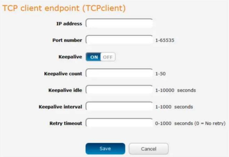
bar
| Category | Value | | ------------------ | --------- | | IP address | | | Port number | 1-65535 | | Keepalive | ON/OFF | | Keepalive count | 1-50 | | Keepalive idle | 1-10000 seconds | | Keepalive interval | 1-1000 seconds | | Retry timeout | 0-1000 seconds (0 = No retry) |Figure 89 - TCP client endpoint configuration
UDP server: This creates a UDP server endpoint with the following options available.
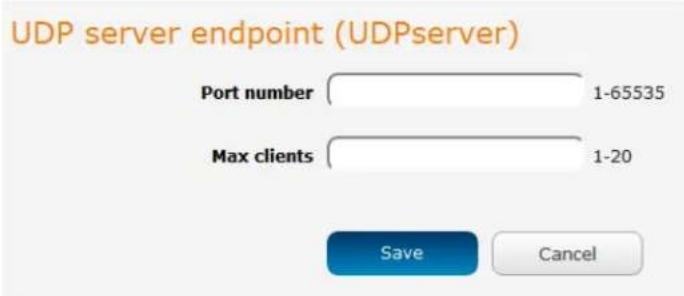
Figure 90 - UDP server endpoint configuration
UDP client: This creates a UDP client endpoint with the following options available. The retry timeout period specifies the number of seconds to wait between attempts to re-establish a connection in the event that it is lost. The client will attempt re-connection indefinitely every Retry timeout interval.
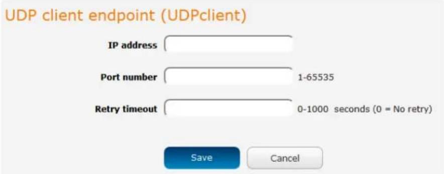
Figure 9.1 - UDP client endpoint configuration
GPS data: This creates a GPS data endpoint.
Figure 92 - GPS data endpoint configuration
- Click the OK button. The router displays a screen with configuration options for your chosen endpoint type.
- Enter the options for your endpoint as required.
- Click the Save button. The Endpoints list is displayed with the newly created endpoint listed and a summary of the settings your configured.
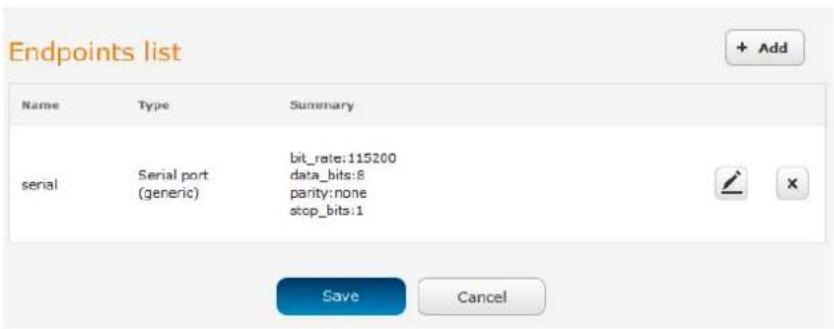
Figure 93 - Endpoints list
Streams
When you have created the required endpoints, you can then proceed to set up a data stream. A data stream sends data from one endpoint to another, performing any transformation of the data as required. When a stream is added, an underlying process on the router checks the validity of the stream, checking for conflicts and illogical configurations.

Notes on data stream operation:
- When any changes to the Data stream manager configuration are detected, all data streams are stopped and restarted as per the new configuration.
• Multiple Modbus clients cannot connect simultaneously to Modbus serial slaves connected to the router.
Every stream requires two endpoints, Endpoint A and Endpoint B. In all cases, the flow of data is from Endpoint A to Endpoint B. To create a new stream:
- Click the +Add button on the right side of the page.
Figure 94 - Data stream list
The Edit data stream page is displayed.
- In the Data stream name field, enter a name for the Data stream.
-
Under Endpoint A, use the Endpoint name drop down list to select one of the endpoints you created previously. This endpoint should be the starting point of the stream. Use the Mode drop down list to select the mode of operation of the endpoint. The mode can be thought of as a transformation of the data as it leaves this endpoint. For example, if Endpoint A type is Serial port (generic), the Mode can be set to various Modbus server and client types. This means that upon arrival at Endpoint A, the data will be transformed into the chosen Modbus format, ready to be sent to Endpoint B.
-
Under Endpoint B, use the Endpoint name drop down list to select one of the endpoints you created previously. This endpoint should be the destination of the stream. The screenshot below shows a configuration sending data received on an attached serial port to a TCP server running on the router. Use the Mode drop down list to select the mode of operation of the endpoint. The mode can be thought of as a transformation of the data as it arrives at this endpoint.
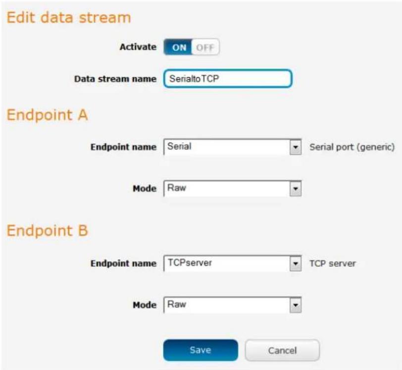
Figure 95 · Edit data stream
- Click the Save button. The new stream appears in the Data stream list.
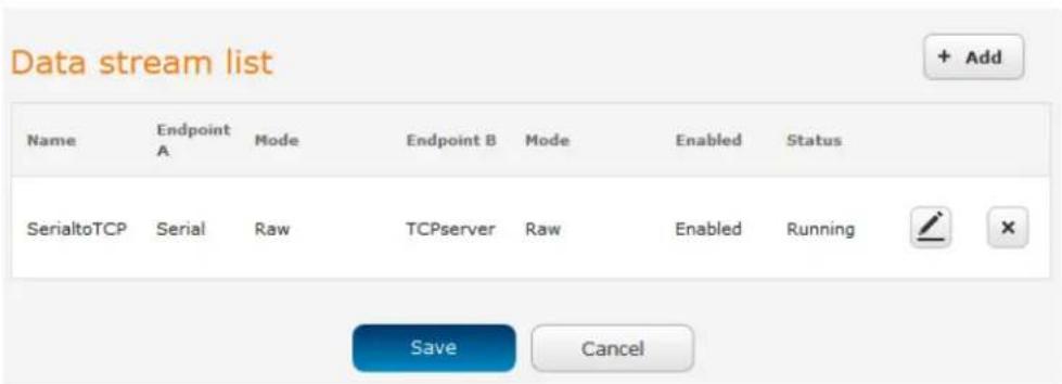
Figure 96 - Data stream list
PADD
PAD Daemon is a tool used to encapsulate raw serial data into a TCP packet to be transported over IP to another end point. The server receiving the TCP packets unpacks the data and the original raw serial data is passed out of its serial port to the attached device, thereby creating an invisible IP network to the two serial devices.
The PAD Daemon runs as a background process which can be accessed via the web configuration interface. The PADD configuration page is located under "Services > PADD". The PADD is used usually with multiple connections or when redundant connections are needed. The PADD has two modes: the PADD TCP/IP Server mode and PADD TCP/IP Client Mode. When PADD is enabled, both the PADD server mode and PADD client mode can be run at the same time.
The PADD configuration page is shown below.
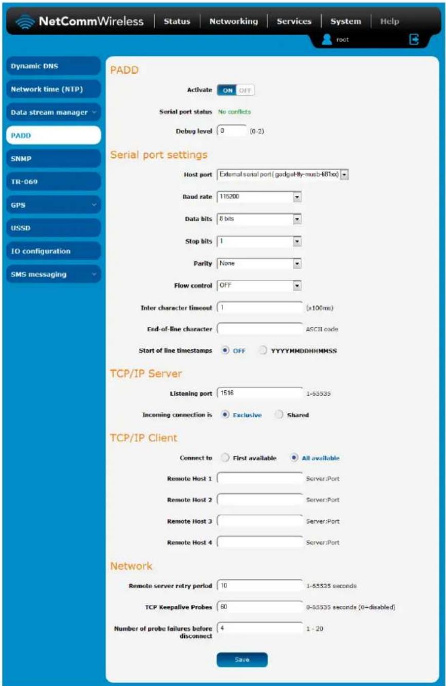
Figure 97 - PADD
SNMP
SNMP configuration
The SNMP page is used to configure the SNMP features of the router.
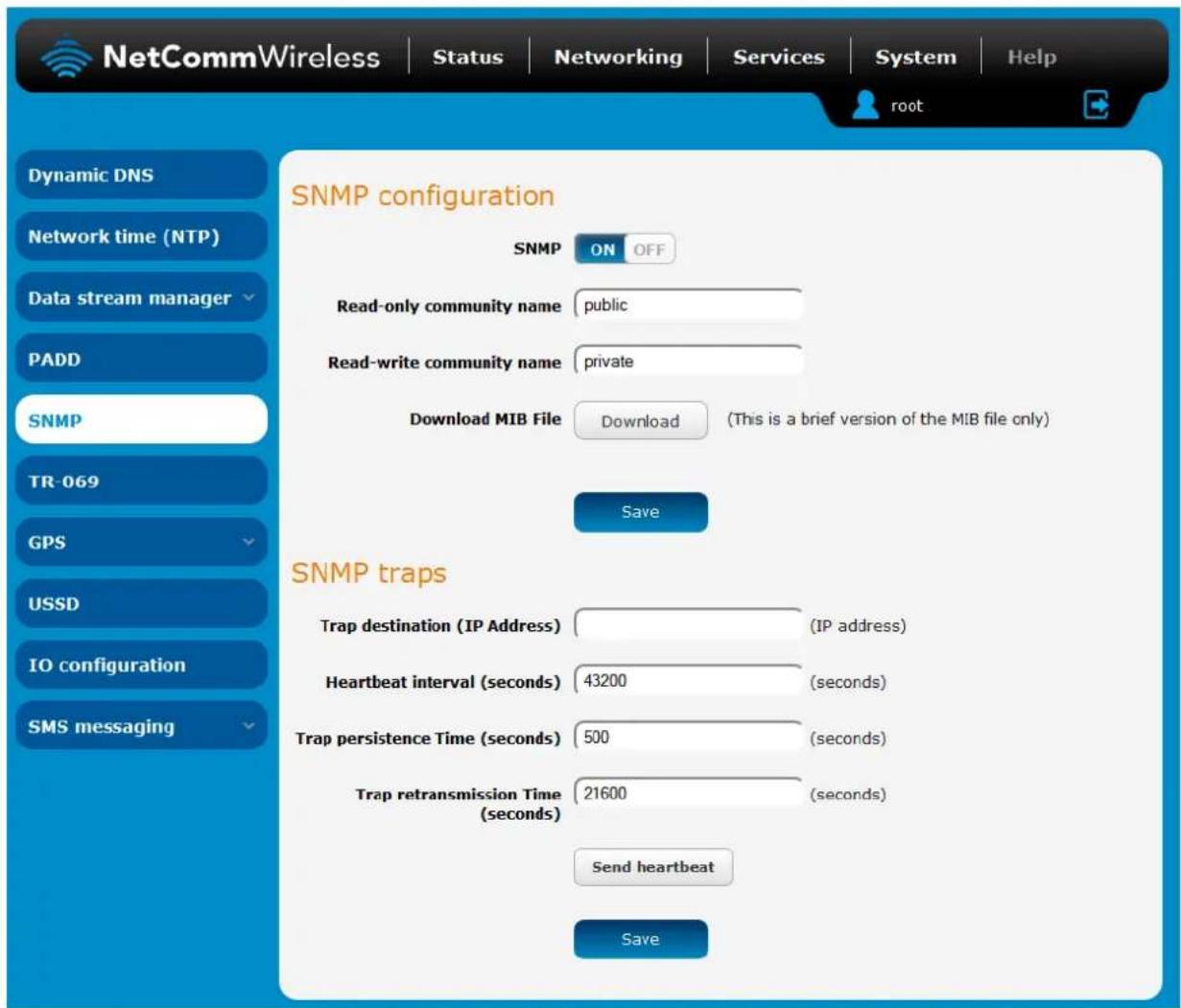
Figure 98 - SNMP configuration
SNMP (Simple Network Management Protocol) is used to remotely monitor the router for conditions that may warrant administrative attention. It can be used to retrieve information from the router such as the signal strength, the system time and the interface status.
To configure SNMP:
- Click the SNMP toggle key to switch it to the ON position.
- Enter Read-only community name and Read-write community name which are used for client authentication.

Community names are used as a type of security to prevent access to reading and/or writing to the routers configuration. It is recommended that you change the Community names to something other than the default settings when using this feature.
- Click the Save button to save any changes to the settings.
The Download button displays the Management Information Base (MIB) of the router. The MIB displays all the objects of the router that can have their values set or report their status. The MIB is formatted in the SNMP-related standard RFC1155.
SNMP traps
SNMP traps are messages from the router to the Network Management System sent as UDP packets. They are often used to notify the management system of any significant events such as whether the link is up or down.
Configuring SNMP traps
To configure SNMP traps:
- In the Trap destination field, enter the IP address to which SNMP data is to be sent.
- In the Heartbeat interval field, enter the number of seconds between SNMP heartbeats.
- Use the Trap persistence field to specify the time in seconds that an SNMP trap persists.
- Use the Trap retransmission time to specify the length of time in seconds between SNMP trap retransmissions.
SNMP traps
Trap destination (IP address) 192.168.1.101
Heartbeat interval [43200 (seconds)
Trap persistence time [500 (seconds)
Trap retransmission time [21600 (seconds)
Send heartbeat
Save
Figure 99 - SNMP traps
To send a manual SNMP Heartbeat, click the Send heartbeat button. When you have finished configuring the SNMP traps, click the Save button to save the settings.

Note: When a factory reset is performed via SNMP, the SNMP settings are preserved.
TR-069
To access the TR-069 configuration page, click the Services menu item, then select the TR-069 menu item on the left.
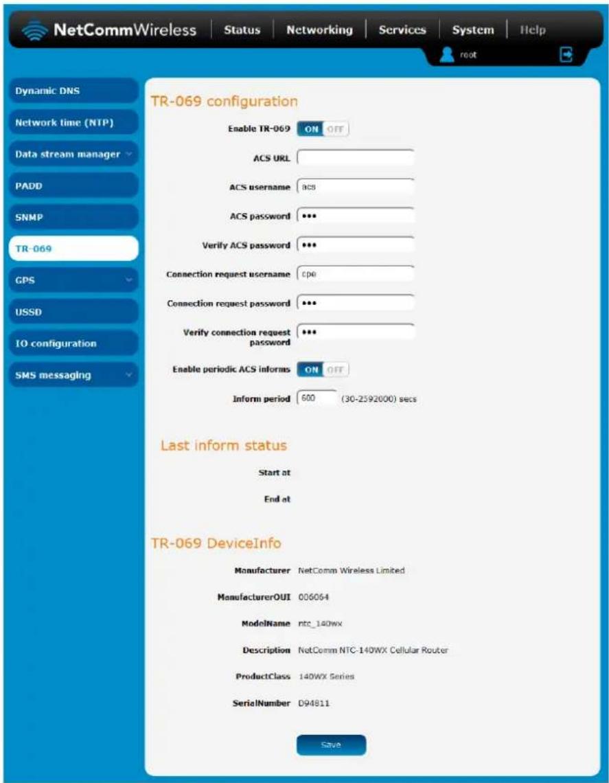
Figure 100 - TR-069 configuration
The TR-069 (Technical Report 069) protocol is a technical specification also known as CPE WAN Management Protocol (CWMP). It is a framework for remote management and auto-configuration of end-user devices such as customer-premises equipment (CPE) and Auto Configuration Servers (ACS). It is particularly efficient in applying configuration updates across networks to multiple CPEs.
TR-069 uses a bi-directional SOAP/HTTP-based protocol based on the application layer protocol and provides several benefits for the maintenance of a field of CPEs:
Simplifies the initial configuration of a device during installation
Enables easy restoration of service after a factory reset or replacement of a faulty device
Firmware and software version management
Diagnostics and monitoring

Note: You must have your own compatible ACS infrastructure to use TR-069. In order to access and configure the TR-069 settings you must be logged into the router as the root user.

Note: When a factory reset of the router is performed via TR-069, the TR-069 settings are preserved.
TR-069 configuration
To configure TR-069:
- Click the Enable TR-069 toggle key to switch it to the ON position.
- In the ACS URL field, enter the Auto Configuration Server's full domain name or IP address.
- Use the ACS username field to specify the username for the Auto Configuration Server.
- In the ACS password and Verify ACS password fields, enter the Auto Configuration Server password.
- In the Connection Request Username field, enter the username to use for the connection requests.
- In the Connection Request Password and Verify password fields, enter the connection request password.
- The inform message acts as a beacon to inform the ACS of the existence of the router. Click the Enable periodic ACS informs toggle key to turn on the periodic ACS inform messages.
- In the Inform Period field, enter the number of seconds between the inform messages.
- Click the Save button to save the settings.
GPS
On models with a built-in GPS, you are able to use location-based services, monitor field deployed hardware or find your current location. The GPS Status window provides up to date information about the current location and the current GPS signal conditions (position dilution of precision (PDOP), horizontal dilution of precision (HDOP) and vertical dilution of precision (VDOP)) of the router.
NMEA support
The router supports the National Marine Electronics Association NMEA-0183 compatible (V2.3) standard of sending GPS data. The standard includes "sentences" used to identify the type of data being sent and therefore defines the way the data is interpreted. The supported GPS related sentences are listed below:
GPGGA – Global Positioning System Fix Data, Time, Position and fix related data for a GNSS receiver
GPRMC – Recommended minimum data for GPS
GPGSV – Detailed satellite data
GPGSA – Overall satellite data
GPVTG – Vector track and speed over the Ground
GPS configuration
To access the GPS configuration screen, select the Services item from the top menu bar then the GPS item on the left. Finally, select the GPS configuration menu item.
To use the GPS function, set the GPS operation toggle key to ON and click the Save button.
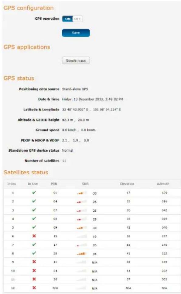
Figure 101-GPS configuration
The Google maps button provides a quick short cut to show your router's current position on a map.
Mobile Station Based Assisted GPS configuration
To access the Mobile Station Based Assisted GPS configuration screen, select the Services item from the top menu bar then the GPS item on the left. Finally, select the MSB (A-GPS) menu item. This function is only available on models with built-in GPS capability.
Mobile Station Based Assisted GPS (MSB A-GPS) enables your router to download GNSS data which supply orbital data to GPS receiver, enabling it to lock to the satellites more rapidly. The GNSS data is stored on the router to assist the GPS in locating the router.
To set up automatic updates of GNSS data, set the A-GPS Enable toggle key to the ON position and use the drop down lists to configure the automatic retry options. Each retry, the router checks for an updated GNSS data file and downloads the GNSS data if newer than the currently stored data.

Note: When new GNSS data is available and the router performs an update, up to 40MB of data may be downloaded. Please keep this in mind if your mobile broadband plan has usage restrictions.
Mobile Station Based Assisted GPS configuration
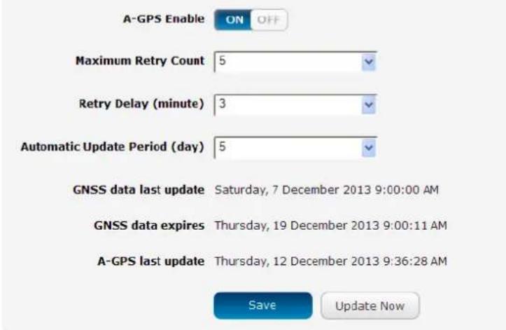
Figure 102 - Mobile Stations Based Assisted GPS configuration options
| ITEM | DESCRIPTION |
| A-GPS Enable | Enables or disables the mobile station based assisted GPS function. |
| Maximum Retry Count | Sets the maximum number of times the router should attempt to triangulate its position. |
| Retry delay (minute) | Sets the number of minutes the router should wait between attempts to triangulate its position. |
| Automatic Update Period (day) | Sets the number of days that the router should automatically update the A-GPS data. The maximum update period is 7 days. |
Table 24 - Mobile Station Based Assisted GPS configuration options
The GNSS data last update field represents the time that the GNSS data file was created while the GNSS data expires field indicates the time that this data is valid until. The A-GPS last update field specifies the last time the router attempted to retrieve an update to the GNSS data.
You may manually force the router to check for an update regardless of the next scheduled update time by clicking the Update Now button.
When you have finished configuring the settings, click the Save button to save the changes.
Odometer
To access the Odometer screen, select the Services item from the top menu bar then the GPS item on the left. Finally, select the Odometer menu item.
The GPS may be used to record the distance that the router has travelled. To do this, set the Odometer toggle key to the ON position as in the screenshot below. You can toggle the unit of measurement by clicking the Display imperial / Display metric button. The threshold setting adjusts the router's sensitivity to movement so that movement within the specified radius from the starting point does not register as distance travelled. When you have finished configuring the Odometer settings, click the Save button to ensure the settings are stored on the router.
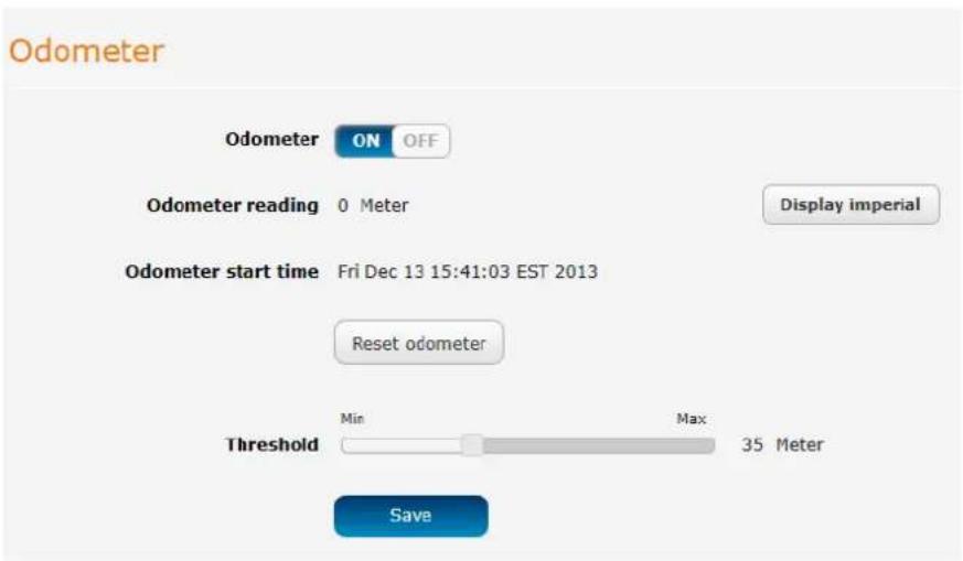
Figure 103 – Odometer options
| ITEM | DESCRIPTION |
| Odometer reading | The number of metres/kilometres that the device has travelled since the time listed in the Odometer start time field. |
| Display imperial / Display metric | Toggles the Odometer reading between metric and imperial measurements. |
| Odometer start time | The time that recording of distance travelled began. |
| Reset odometer | Resets the odometer reading to 0 and the Odometer start time to the current time. |
| Odometer | Toggles the Odometer function on and off. |
| Threshold | Specifies the minimum distance that the router must travel from its current position before the Odometer reading increases. |
Table 25 - Odometer configuration options
USSD
Network Messaging, also known as Unstructured Supplementary Service Data (USSD) is a protocol that can be used to communicate from your device to your service provider. Depending on which network you use for your mobile broadband service, this page can be used for a variety of network services such as balance checking, recharging a prepaid service, and many others.
Network messaging can be initiated using special codes specified by your carrier for these various services. Once a special code is sent to the network, the network responds with the requested information. The response often includes instructions for sending additional follow-on messages allowing further functionality (e.g entering credit card information for a credit recharge).
Please contact your network provider to learn which codes can be used on your network for features such as balance checking, recharge, etc
To begin using this feature, please enter the dial string (e.g #100#) into the box below and click "Start Session". If you don't know which dial string to use, please contact your carrier, and ask them which dial codes are suitable for network services.
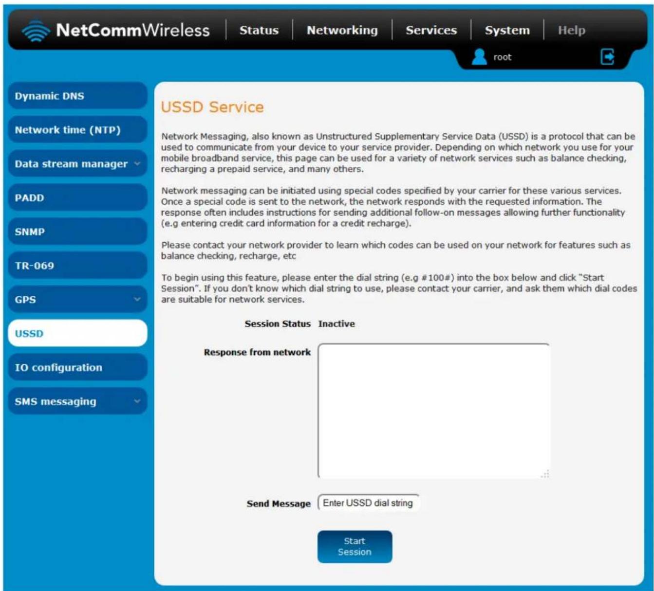
Figure 104 - USSD Service
IO configuration
The NTC-140W Series Router is equipped with a 2 x 2 Molex connector providing Power (+), Ground (−), a multipurpose input and output pin and an ignition detection input. The multipurpose input/output pin may be independently configured for various functions, including:
NAMUR (EN 60947-5-6 / IEC 60947-5-6) compatible proximity sensor input
Proximity sensor input for use with contact closure (open/closed) type of sensors (PIR sensors, door/window sensors for security applications) with the input tamper detection possible (four states detected: open, closed, short and break) by the use of external resistors
Analogue 0V to 30V input
Digital input (the I/O voltage measured by the Analogue input and the software making decision about the input state) with the threshold levels configurable in software
Open collector output.
Use the pull up voltage options to select the desired output voltage of the I/O pins. The pull up voltage you select will be the same for each pin when pull up is enabled for that pin. Each pin is capable of outputting either 3.3V or 8.2V.
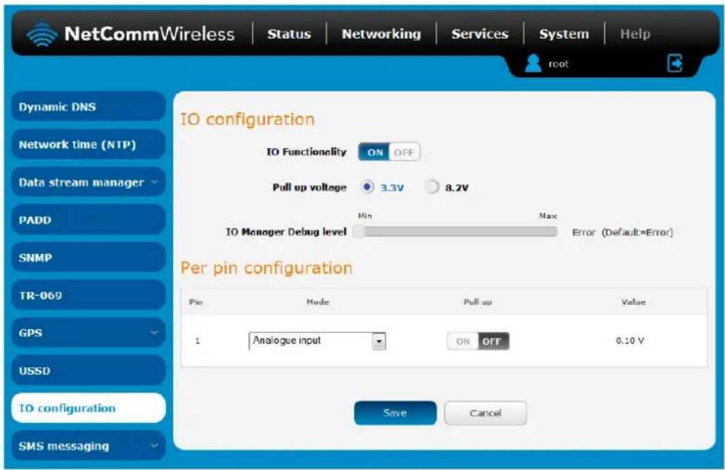
Figure 105-10 configuration options
| ITEM | DESCRIPTION |
| IO configuration | |
| IO Functionality | Enables the configuration of the input and output pins on the 2x2 Molex connector. |
| Pull up voltage | Specifies the output voltage of the I/O pins. |
| IO Manager Debug level | Use the slide bar to adjust the level of detail you would like to see in the log for IO messages. A higher debug level displays more detailed messages in the log file. |
| Per pin configuration | |
| Pin | The I/O pin number corresponding to the pin on the Molex connector that you wish to configure. |
| Mode | The mode of operation for the corresponding pin. Available options are Digital input, Digital output, Analogue Input, Namur input, Contact closure input. |
| Pull up | Use the pull up toggle keys to turn the pull up on or off for the corresponding pin. When turned on, the pull up voltage output is the value specified in the “Pull up voltage” option. |
| Value | The value column displays whether the voltage detected on the line is low or high or allows you to configure the output value in the case that the pin is set to digital output. This can be useful for applications where monitoring of the transition between low and high is used to trigger an action. |
Table 26 - 10 configuration options
The table below describes the different modes available on the physical I/O pins of the router.
| MODE | DESCRIPTION |
| Digital input | The corresponding pin accepts digital input. Pull up may be on or off and both 3.3V and 8.2V are available as pull up voltages. The value column displays whether the signal received on the pin is High or Low. |
| Digital output | The corresponding pin outputs a digital signal. Pull up may be on or off and both 3.3V and 8.2V are available as pull up voltages. The value column contains a toggle key allowing you to set whether the output signal is High or Low. |
| Analogue input | The corresponding pin accepts an analogue signal. Pull up may be on or off and both 3.3V and 8.2V are available as pull up voltages. The value column displays the current voltage detected on the pin. |
| Namur input | NAMUR is a sensor standard using low-level current signals. It can supply two different signal levels depending on the state of the switch and is commonly used in hazardous or explosive locations where compact sensors are required.When a pin is set to NAMUR mode, Pull up is turned on and the global Pull up voltage is set to 8.2V. These settings may not be changed for as long as a pin is set to NAMUR mode as they are required settings according to the NAMUR IEC 60947-5-6 standard. The value column displays whether the signal received on the pin is High or Low. |
| Contact closure input | A common type of digital input where a sensor or switch opens or closes a set of contacts as a result of a process change. An electrical signal is then used to determine whether the circuit is open or closed.When a pin is set to Contact closure input, Pull up is enabled for that pin and may not be turned off as long as the pin remains configured as a Contact closure input. Global pull up voltage may be either 3.3V or 8.2V. |
Table 27-10 pin modes

Note: Please refer to the SDK Developer Guide for hardware information about the Input/Output pins, wiring examples and configuration of the pins via the command line interface. There are also wiring examples in Appendix G of this User Guide. Contact NetComm Wireless Technical Support for access to the Software Development Kit.
SMS messaging
The NTC-140W Series router offers an advanced SMS feature set, including sending messages, receiving messages, redirecting incoming messages to another destination, as well as supporting remote commands and diagnostics messages.
Some of the functions supported include:
Ability to send a text message via a cellular network and store it in permanent storage.
Ability to receive a text message via a cellular network and store it in permanent storage.
Ability to forward incoming text messages via a cellular network to another remote destination which may be a TCP/UDP server or other mobile devices.
Ability to receive run-time variables from the device (e.g. uptime) on request via SMS
Ability to change live configuration on the device (e.g. network username) via SMS.
Ability to execute supported commands (e.g. reboot) via SMS
Ability to trigger the NTC-140W Series router to download and install a firmware upgrade
Ability to trigger the NTC-140W Series router to download and apply a configuration file
To access the SMS messaging functions of the NTC-140W Series router, click on the Services menu item from the top menu bar, and then select one of the options under the SMS messaging section on the left hand menu.
Setup
The Setup page provides the options to enable or disable the SMS messaging functionality and SMS forwarding functionalities of the router. SMS messaging is enabled by default.
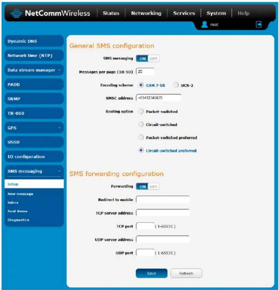
Figure 106 - General SMS Configuration
| OPTION | DEFINITION |
| General SMS configuration | |
| SMS messaging | Toggles the SMS functionality of the router on and off. |
| Messages per page (10-50) | The number of SMS messages to display per page. Must be a value between 10 and 50. |
| Encoding scheme | The encoding method used for outbound SMS messages. GSM 7-bit mode permits up to 160 characters per message but drops to 50 characters if the message includes special characters. UCS-2 mode allows the sending of Unicode characters and permits a message to be up to 50 characters in length. |
| SMS forwarding configuration | |
| Forwarding | Toggles the SMS forwarding function of the router on and off. |
| Redirect to mobile | Enter a mobile number as the destination for forwarded SMS messages. |
| TCP server address | Enter an IP address or domain name as the destination for forwarded SMS messages using TCP. |
| TCP port | The TCP port on which to connect to the remote destination. |
| UDP server address | Enter an IP address or domain name as the destination for forwarded SMS messages using UDP. |
| UDP port | The UDP port on which to connect to the remote destination. |
Table 28 - SMS Setup Settings
SMS forwarding configuration
Incoming text messages can be redirected to another mobile device and/or a TCP/UDP message server.
Redirect to mobile
You can forward incoming text messages to a different destination number. This destination number can be another mobile phone or a router phone number.
For Example:
If someone sends a text message and Redirect to mobile is set to "+61412345678", the text message is stored on the router and forwarded to "+61412345678" at the same time.
To disable redirection to a mobile, clear the Redirect to mobile field and click the Save button.
Redirect to TCP / UDP server address
You can also forward incoming text messages to a TCP/UDP based destination. The TCP or UDP server can be any kind of public or private server if the server accepts incoming text-based messages.
The TCP/UDP address can be an IP address or domain name. The port number range is from 1 to 65535. Please refer to your TCP/UDP based SMS server configuration for which port to use.
For Example:
If someone sends a text message and TCP server address is set to "192.168.20.3" and TCP port is set to "2002", this text message is stored in the router and forwarded to "192.168.20.3" on port "2002" at the same time.
To disable redirection to a TCP or UDP address, clear the TCP server address and UDP server address fields and click the Save button.
New message
The New message page can be used to send SMS text messages to a single or multiple recipients.
A new SMS message can be sent to a maximum of 9 recipients at the same time. After sending the message, the result is displayed next to the destination number as "Success" or "Failure" if the message failed to send. By default, only one destination number field is displayed. Additional destination numbers may be added one at a time after entering a valid number for the current destination number field. To add a destination number, click the + button and to remove the last destination in the list, click the - button.
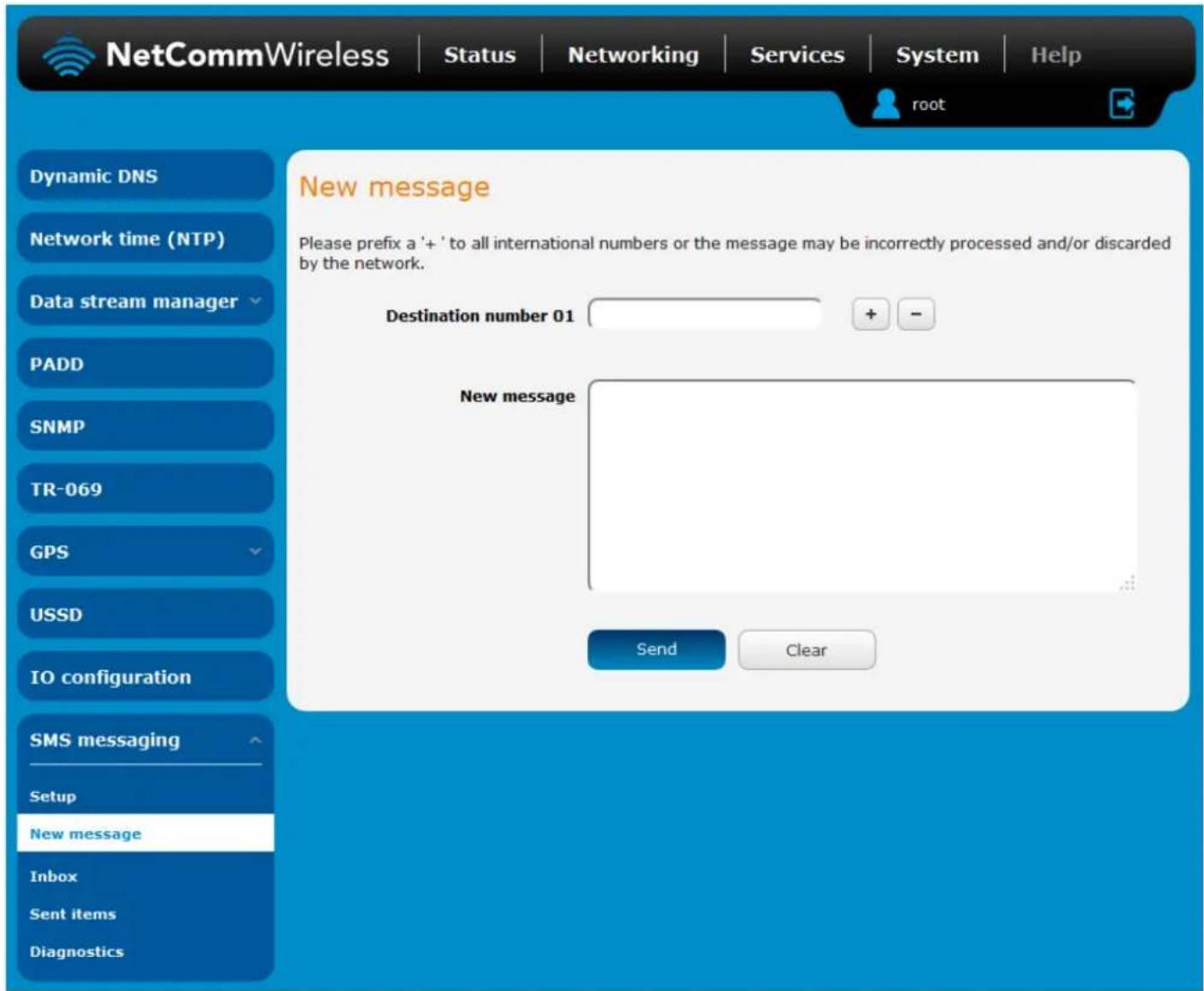
Figure 107 - SMS - New Message
Destination numbers should begin with the "+" symbol followed by the country calling code. To send a message to a destination number, enter the "+" symbol followed by the country calling code and then the destination number.
For example:
To send a message to the mobile destination number 0412345678 in Australia (country calling code 61), enter "+61412345678".
After entering the required recipient numbers, type your SMS message in the New message field. As you type your message, a counter shows how many characters you have entered out of the total number available for your chosen encoding scheme. When you have finished typing your message and you are ready to send it, click the Send button.
Inbox / Sent Items
The Inbox displays all received messages that are stored on the router while Sent Items displays all sent messages.
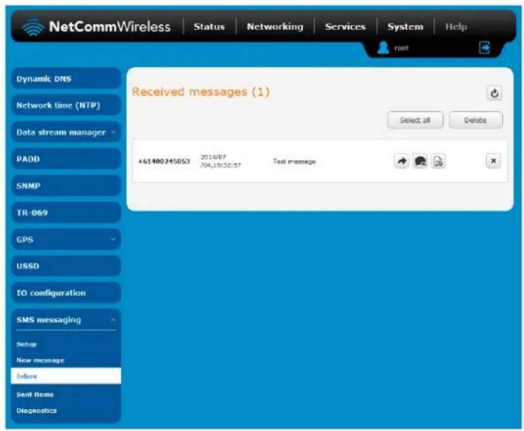
Figure 108 - SMS Inbox
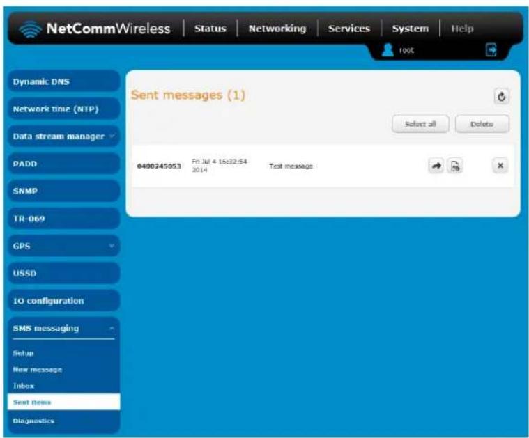
Figure 109 - SMS Outbox
| ICON | DESCRIPTION |
| Forward button. Click this button to open a new message window where you can forward the corresponding message to another recipient. | |
| Reply button. Click this button to open a new message window where you can reply to the sender. | |
| Add to White list. Click this button to add the sender's mobile number to the white list on the router. | |
| Delete button. Click this button to delete the corresponding message. | |
| Refresh button. Click this button to refresh the inbox or outbox to see new messages. |
Table 29 - Inbox/Outbox icons
Diagnostics
The Diagnostics page is used to configure the SMS diagnostics and command execution configuration. This allows you to change the configuration, perform functions remotely and check on the status of the router via SMS commands.
To access the Diagnostics page, click on the Services menu item then select the SMS menu on the left and finally select Diagnostics beneath it.
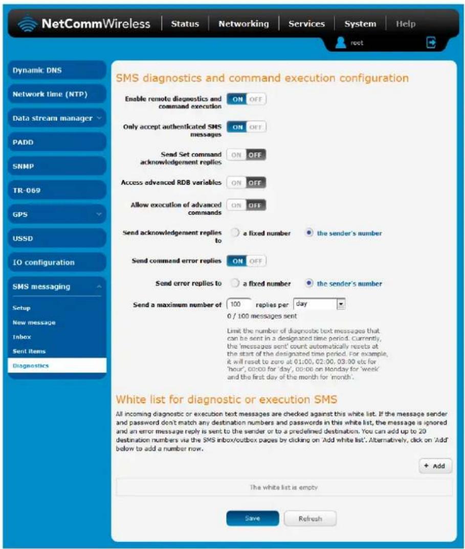
Figure 110 - SMS diagnostics and command execution configuration
SMS diagnostics and command execution configuration
The options on this page are described below.
Enable remote diagnostics and command execution
Enables or disables the remote diagnostics feature. If this setting is enabled all incoming text messages are parsed and tested for remote diagnostics commands.
If remote diagnostics commands are found, the router executes those commands. This feature is enabled by default. All remote diagnostic commands that are received are stored in the Inbox.

Note: It is possible to adjust settings and prevent your router from functioning correctly using remote diagnostics. If this occurs, you will need to perform a factory reset in order to restore normal operation.

We highly recommended that you use the white list and a password when utilising this feature to prevent unauthorised access. See the White list description for more information.
Only accept authenticated SMS messages
Enables or disables checking the sender's phone number against the allowed sender white list for incoming diagnostics and command execution SMS messages.
If authentication is enabled, the router will check if the sender's number exists in the white list. If it exists, the router then checks the password (if configured) in the incoming message against the password in the white list for the corresponding sending number. If they match, the diagnostic or command is executed.
If the number does not exist in the white list or the password does not match, the router does not execute the incoming diagnostic or command in the SMS message.
This is enabled by default and it is strongly advised that you leave this feature enabled to maintain security.
Send Set command acknowledgement replies
The NTC-140W Series router will automatically reply to certain types of commands received, such as get commands, or execute commands. However acknowledgement replies from the NTC-140W Series router are optional with set commands and the Wakeup command. This option Enables or disables sending an acknowledgment message after execution of a set command or SMS Wakeup command. If disabled, the router does not send any acknowledgement after execution of a set command or SMS Wakeup command. All acknowledgment replies are stored in the Outbox after they have been sent. This can be useful to determine if a command was received and executed by the router. This option is disabled by default.
Access advanced RDB variables
By default, this option is turned off and only allows access to the basic RDB variables listed later in this guide. If this option is enabled, you are able to access the full list of RDB variables via SMS.
Allow execution of advanced commands
By default, this option is turned off and only allows execution of the basic commands listed later in this guide. If this option is enabled, you are able to execute advanced commands such as those which are common to the Linux command line. For example: "execute ls /usr/bin/sms*" to list the contents of the /etc folder on the router.
Send acknowledgement replies to
This option allows you to specify where to send acknowledgment messages after the execution of a set, get, or exec command.
If a fixed number is selected, the acknowledgement message will be sent to the number defined in the Fixed number to send replies to field. If the sender's number is selected, the acknowledgement message will be sent to the number that the SMS diagnostic or command message originated from. The default setting is to use the sender's number.
Fixed number to send replies to
This field defines the destination number to which error messages are sent after the execution of a get, set, or exec command. This field is only displayed when Send Error SMS to is set to Fixed Number.
Send command error replies
Enables or disables the sending of an error message resulting from the execution of a get, set, or exec command. All error replies are stored in the Outbox after they have been sent.
Send error replies to
When Send Error SMS for Get/Set/Exec Command is set to ON, this option is used to specify where the error SMS is sent. Use the radio buttons to select either Fixed Number or SMS Sender Number. When set to SMS Sender Number the router will reply to the originating number of the SMS diagnostic or command. When set to Fixed Number the router will send the error messages to the number specified in the following field.
Send a maximum number of
You can set the maximum number of acknowledgement and error messages sent when an SMS diagnostic or command is executed. The maximum limit can be set per hour, day, week or month. The router will send a maximum of 100 replies by default.
The number of messages sent is shown below the options. The total transmitted message count resets after a reboot or at the beginning of the time frame specified.
White List for diagnostic or execution SMS
The white list is a list of mobile numbers that you can create which are considered "friendly" to the router. If Only accept authenticated SMS messages is enabled in the diagnostics section, the router will compare the mobile number of all incoming diagnostic and command messages against this white list to determine whether the diagnostic or command should be executed. You may optionally configure a password for each number to give an additional level of security. When a password is specified for a number, the SMS diagnostic or command message is parsed for the password and will only be executed if the number and password match.

Figure 111 - White list for diagnostic or execution SMS
A maximum of 20 numbers can be stored on the router in the white list. To add a number to the white list, click the "+Add" button.
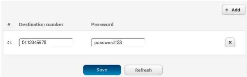
Figure 112—Adding a number to the SMS white list
The White List numbers and passwords can be cleared by pressing the ✗ button to the right of each entry. To add a number to the white list, enter it in the Destination number field and optionally define a password in the Password field. When you have finished adding numbers click the Save button to save the entries.
Sending an SMS Diagnostic Command
Follow the steps below to configure the router to optionally accept SMS diagnostic commands only from authenticated senders and learn how to send SMS diagnostic commands to the router.
- Navigate to the Services > SMS messaging > Diagnostics page
- Confirm that the Enable remote diagnostics and command execution toggle key is set to the ON position. If it is set to OFF click the toggle key to switch it to the ON position.
- If you wish to have the router only accept commands from authenticated senders, ensure that Only accept authenticated SMS messages is set to the ON position. In the White list for diagnostic or execution SMS messages section, click the +Add button and enter the sender's number in international format into the Destination number field that appears. If you wish to also configure a password, enter the password in the Password field corresponding to the destination number.
- If you would prefer to accept SMS diagnostic commands from any sender, set the Only accept authenticated SMS messages toggle key to the OFF position.

Note: An alternative method of adding a number to the white list is to send an SMS message to the router, navigate to Services > SMS messaging > Inbox and then click the button next to the message which corresponds to the sender's number.
- Click the Save button.
Types of SMS diagnostic commands
There are three types of commands that can be sent; execute, get and set. The basic syntax is as follows:
execute COMMAND
get VARIABLE
set VARIABLE=VALUE
If authentication is enabled, each command must be preceded by the password:
PASSWORD execute COMMAND
PASSWORD get VARIABLE
PASSWORD set VARIABLE=VALUE
The following are some examples of SMS diagnostic commands:
password6657 execute reboot
get rssi
set apn1=testAPNvalue
SMS acknowledgment replies
The router automatically replies to get commands with a value and execute commands with either a success or error response. Set commands will only be responded to if the Send Set command acknowledgement replies toggle key is set to ON. If the Send command error replies toggle key is set to ON, the router will send a reply if the command is correct but a variable or value is incorrect, for example, due to misspelling.
SMS command format
Generic Format for reading variables:
get VARIABLE
PASSWORD get VARIABLE
Generic Format for writing to variables:
set VARIABLE=VALUE
PASSWORD set VARIABLE=VALUE
Generic Format for executing a command:
Execute COMMAND
PASSWORD execute COMMAND
Replies
Upon receipt of a successfully formatted, authenticated (if required) command, the gateway will reply to the SMS in the following format:
| TYPE | SMS CONTENTS | NOTES |
| get command | "VARIABLE=VALUE" | |
| set command | "Successfully set VARIABLE to VALUE" | Only sent if the acknowledgment message function is enabled |
| execute command | "Successfully executed command COMMAND" |
Table 30 - SMS Diagnostic Command Syntax
Where "VARIABLE" is the name of the value to be read
Where "VARIABLE (x)" is the name of another value to be read
Where "VALUE" is the content to be written to the "VARIABLE"
Where "COMMAND" is a supported command to be executed by the device (e.g. reboot)
Where "PASSWORD" is the password (if configured) for the corresponding sender number specified in the White List
Multiple commands can be sent in the same message, if separated by a semicolon.
For Example:
get VARIABLE1; get VARIABLE2; get VARIABLE3
PASSWORD get VARIABLE1; get VARIABLE2
set VARIABLE=VALUE1; set VARIABLE2=VALUE2
PASSWORD set VARIABLE1=VALUE1; set VARIABLE2=VALUE2; set VARIABLE3=VALUE3
If required, values can also be bound by an apostrophe, double apostrophe or back tick.
For Example:
“set VARIABLE='VALUE'"
“set VARIABLE="VALUE””
“set VARIABLE=VALUE”
"get VARIABLE"
A password (if required), only needs to be specified once per SMS, but can be prefixed to each command if desired.
"PASSWORD get Variable1"; "get VARIABLE2"
"PASSWORD set VARIABLE1=VALUE1"; "set VARIABLE2=VALUE2"
If the command sent includes the "reboot" command and has already passed the white list password check, the device keeps this password and executes the remaining command line after the reboot with this same password.
For Example:
"PASSWORD execute reboot; getVariable1"; "get VARIABLE2"
"PASSWORD execute reboot; PASSWORD get Variable1"; "get VARIABLE2"

Note: Commands, variables and values are case sensitive.
List of basic commands
A list of basic commands which can be used in conjunction with the execute command are listed below:
"pdpcycle", "pdpdown" and "pdpup" commands can have a profile number suffix 'x' added. Without the suffix specified, the command operates against the default profile configured on the profile list page of the Web-Ul.
| # | COMMAND NAME | DESCRIPTION |
| 1 | reboot | Immediately performs a soft reboot. |
| 2 | pdpcycle | Disconnects (if connected) and reconnects the data connection. If a profile number is selected in the command, try to disconnect/reconnect the specified profile in case the profile is active. If no profile number is selected, try to disconnect/reconnect the current active profile. Reports an error if no profile number is selected and there is no currently activated profile. |
| 3 | pdpdown | Disconnects the PDP. If a profile number is selected in the command, the router tries to disconnect the specified profile in case the profile is active. If no profile number is selected, try to disconnect the current active profile. Reports an error if no profile number is selected and there is no currently activated profile. |
| 4 | pdpup | Reconnects the PDP. If a profile number is selected in the command, the router tries to connect with the specified profile. If no profile number is selected, the router tries to connect to the last active profile. The gateway will check the currently activated profile and disconnect this profile before executing the command. The router reports an error if no profile number is selected and there is no stored last active profile number. |
| 5 | factorydefaults | Performs a factory reset on the router. Be aware that this command also clears the SMS white list on the router. |
| 6 | download | Performs a download and install of a Firmware Upgrade (.cdi), Config File (.tar.gz) or a help document (.pdf) file.If the file is a firmware image as in the case of a .cdi file, the router will apply the recovery image first and then the main firmware image. The download location is specified immediately after the command and may be from an HTTP or FTP source URL.If the file is a .tar.gz file, the router will apply the file as a configuration file update for the device and reboot afterwards.If the file is a .pdf, the router will assume this is a user guide document and save it to the router and make the file available for viewing via the help menu on the Web-UI.Note: If your download URL includes any space characters, please encode these prior to transmission according to RFC1738, for example:ftp://username:password@serveraddress/directory%20with%20spaces/filename.cdiNote: Authenticated FTP addresses may be used following the format as defined in RFC1738, for example:ftp://username:password@serveraddress/directory/filename.cdi |
| 7 | codconnect | Causes the router to activate the PDP context when the Connect on demand feature is enabled. |
| 8 | coddisconnect | Causes the router to de-activate the PDP context when the Connect on demand feature is enabled. |
| 9 | wakeup | This forces the default Data connection profile to connect if it is in a disconnected or waiting state. There are two circumstances in which this command may be useful; where the default profile is enabled but has been manually disconnected and if Connect on demand is enabled and the router is awaiting packet of interest. In both of these situations, the wakeup command will cause the default PDP context to activate. |
| 10 | ssh.genkeys | Instructs the router to generate new public SSH keys. |
| 11 | ssh.clearkeys | Instructs the router to clear the client public SSH key files. |
Table 31 - List of basic SMS diagnostic commands
List of get/set commands
The following table is a partial list of get and set commands which may be performed via SMS.
| COMMAND NAME | EXAMPLE | DESCRIPTION |
| get status | get status | Returns the Module firmware version, LAN IP Address, Network State, Network operator and RSSI. |
| got sessionhistory | got sessionhistory | Returns the time and date of recent sessions along with the total amount of data sent and received for each session. |
| set syslogserver | set syslogserver=123.45.67.89:514 | Sets a remote syslog server IP or hostname and port. |
| set cod | set cod=1 | Enables or disables Connect on demand. |
| get cod | get cod | Returns the enable/disable status of the Connect on demand feature. |
| got codstatus | got codstatus | Returns the connection status of the Connect on demand feature. |
| set coddialport | set coddialport=on,53 | Sets the Connect on demand feature to connect only when traffic is received on the specified port. |
| get coddialport | get coddialport | Returns the Connect on demand port filter status and list or filtered ports. |
| set codonline | set codonline=20 | Sets the router to stay online for at least X minutes when data activity is detected. |
| get codonline | get codonline | Returns the number of minutes the router is configured to stay online when data activity is detected. |
| set codminonline | set codminonline=10 | Sets the router to stay online for a minimum of X minutes after connecting. |
| get codminonline | get codminonline | Returns the minimum number of minutes the router should stay online after connecting. |
| set codredial | set codredial=5 | Sets the number of minutes that the router should not attempt to redial after hanging up. |
| get codredial | get codredial | Returns the number of minutes that the router is configured to not attempt to redial after hanging up. |
| set coddisconnect | set coddisconnect=0 | Sets the number of minutes after which the router should disconnect regardless of traffic. |
| get coddisconnect | get coddisconnect | Returns the number of minutes the router is configured to disconnect regardless of traffic. |
| set codconnectreg | set codconnectreg=30 | Sets the number of minutes that the router should regularly attempt to connect. |
| get codconnectreg | get codconnectreg | Returns the number of minutes that the router is configured to regularly attempt to connect. |
| set codrandomtime | set codrandomtime=3 | Sets the number of minutes that the router should randomise the dial time by. |
| get codrandomtime | get codrandomtime | Returns the number of minutes that the router is configured to randomise the dial time by. |
| set codverbose | set codverbose=1 | Sets verbose logging on or off. |
| get codverbose | get codverbose | Returns the status of verbose logging. |
| set codignore icmp | set codignore icmp=1 | Sets the router to ignore ICMP packets triggering data activity detection. |
| get codignore icmp | get codignore icmp | Returns the status of the Ignore ICMP option. |
| set codignore.tcp | set codignore.tcp=1 | Sets the router to ignore TCP packets triggering data activity detection. |
| get codignore.tcp | get codignore.tcp | Returns the status of the Ignore TCP option. |
| set codignore.udp | set codignore.udp=1 | Sets the router to ignore UDP packets triggering data activity detection. |
| get codignore.udp | get codignore.udp | Returns the status of the Ignore UDP option. |
| set codignore.dns | set codignore.dns=1 | Sets the router to ignore DNS traffic triggering data activity detection. |
| get codignore.dns | get codignore.dns | Returns the status of the Ignore DNS option. |
| set codignore.ntp | set codignore.ntp=1 | Sets the router to ignore NTP traffic triggering data activity detection. |
| get codignore.ntp | get codignore.ntp | Returns the status of the Ignore NTP option. |
| set codignore.ncsi | set codignore.ncsi=1 | Sets the router to ignore NCSI traffic triggering data activity detection. |
| get codignore.ncsi | get codignore.ncsi | Returns the status of the Ignore NCSI option. |
| get plmnscan | get plmnscan | Instructs the router to perform a network scan and returns the results by SMS. |
| set forceplmn | set forceplmn=505,3 | Sets the operator to a manual selection made by the user where "505" is the Mobile Country Code for Australia and "3" is the Mobile Network Code for Vodafone. As no network type (e.g., LTE/3G/2G) is specified, it is selected automatically. |
| get forceplmn | get forceplmn | Returns the operator and network type selection mode (Automatic/Manual), in addition to the MCC and MNC values |
| get pppoe | get pppoe | Returns the PPPoE status, currently configured dial string and service name |
| set pppoe | set pppoe=1, telstra.internet, test | Sets the PPPoE status on, APN to telstra.internet, and service name to test. |
| get ledmode | get ledmode | Returns the status of the LED operation mode. |
| set ledmode | set ledmode=10 | Sets the LED operation mode to be always on or to turn off after the specified number of minutes. |
| get ssh.proto | get ssh.proto | Returns the SSH protocol in use. |
| set ssh.proto | set ssh.proto=1,2 | Sets the SSH Protocol to protocol 1, 2 or both (1,2). |
| get ssh.passauth | get ssh.passauth | Returns the status of the SSH Enable password authentication option. |
| set ssh.passauth | set ssh.passauth=1 | Sets the SSH Enable password authentication option on or off. |
| get.ssh.keyauth | get.ssh.keyauth | Returns the status of the SSH Enable key authentication option. |
| set.ssh.keyauth | set.ssh.keyauth=1 | Sets the SSH Enable key authentication option on or off. |
Table 32 - List of get/set commands
List of basic RDB variables
The following table lists valid variables where "x" is a profile number (1-6). If no profile is specified, variables are read from or written to for the current active profile. If a profile is specified, variables are read from or written to for the specified profile number ('x').
| # | RDB VARIABLE NAME | SMS VARIABLE NAME | READ/WRITE | DESCRIPTION | EXAMPLE VALUE |
| 0 | link.profile.1.enablelink.profile.1.apnlink.profile.1.userlink.profile.1.passlink.profile.1.auth_typelink.profile.1.iplocallink.profile.1.status | profile | RW | Profile | Read:(profile no,apn,user,pass,auth,iplocal,status)1,apn,username,password,chap,202.44.185.111,upWrite:(apn, user, pass,auth)apn,username,password |
| 2 | link.profile.1.user | username | RW | Cellular broadband username | Guest, could also return "null" |
| 3 | link.profile.1.pass | password | RW | Cellular broadband password | Guest, could also return "null" |
| 4 | link.profile.1.auth_type | authtype | RW | Cellular broadband Authentication type | "pap" or"chap" |
| 5 | link.profile.1.iplocal | wanip | R | WAN IP address | 202.44.185.111 |
| 6 | wwan.0.radio.information.signal_strength | rssi | R | Cellular signal strength | -65 dBm |
| 7 | wwan.0.imei | imei | R | IMEI number | 357347050000177 |
| 8 | statistics.usage_current | usage | R | Cellular broadband data usage of current session | "Rx 500 bytes, Tx 1024 bytes, Total 1524 bytes" or "Rx 0 byte, Tx 0 byte, Total 0 byte" when wwan down |
| 9 | statistics.usage_current | wanuptime | R | Up time of current cellular broadband session | 1 days 02:30:12 or 0 days 00:00:00 when wwan down |
| 10 | /proc/uptime | deviceuptime | R | Device up time | 1 days 02:30:12 |
| 11 | wwan.0.system_network_status.current_band | band | R | Current band | WCDMA850 |
Table 33 - List of basic SMS diagnostics RDB variables
Network scan and manual network selection by SMS
Performing a network scan
The get plmnscan SMS command enables you to perform a scan of the cellular networks available at the time of the scan.
It returns the following semi-colon separated information for each network in range:
MCC
MNC
Network Type (LTE, 3G, 2G)
Provider's Name
Operator Status (available, forbidden, current)
The following is an example of a response from the get plmnscan SMS command:
plmnscan:505,3,7,vodafone AU,4;505,3,1,vodafone AU,1;505,2,7,YES OPTUS,1;505,2,1,YES OPTUS,1;505,1,1,Telstra Mobile,1;505,1,7,Telstra Mobile,1
| NETWORK TYPE | DESCRIPTION |
| 9 | Indicates an LTE network. |
| 7 | Indicates a 3G network |
| 1 | Indicates a 2G network |
Table 3-4 - Network types returned by get plmnscan SMS command
| OPERATOR STATUS | DESCRIPTION |
| 1 | Indicates an available operator which may be selected. |
| 2 | Indicates a forbidden operator which may not be selected (applies only to generic SIM cards). |
| 4 | Indicates the currently selected operator. |
Table 3.5 - Operator status codes returned by get plmnscan SMS command

Notes about the network connection status when using the get plmnscan command:
- If the connection status is Up and connection mode is Always on, the get plmnscan SMS will cause the connection to disconnect, perform the scan, send the result through SMS and then bring the connection back up again. If the connection status is Down, the router will perform the PLMN scan, send the result and keep the connection status down.
- If the connection status is Waiting and connection mode is Connect on demand, the get plmnscan SMS will change the connection status to Down, perform the scan, send the result through SMS and then restore the connection status to the Waiting state.
- If the connection status is Up and connection mode is Connect on demand, the get plmnscan SMS will cause the connection to disconnect, perform the scan, send the result through SMS, and then restore the connection status to the Waiting state unless there is a traffic which triggers a connection in which case the connection status will be set to Up.
Setting the router to connect to a network
The router can be instructed by SMS to connect to one of the networks returned by the get plmnscan command. The set forceplmn command forces the router to connect to a specified operator network (if available) while the get forceplmn command retrieves the currently configured network on the router.
Command format:
set forceplmn=0|MCC,MNC| MCC,MNC,Network Type
For example:
set forceplmn=0
Sets the selection of operator and network type to automatic mode.
set forceplmn=505,3
Sets the operator to a manual selection made by the user where "505" is the Mobile Country Code for Australia and "3" is the Mobile Network Code for Vodafone. As no network type (e.g. LTE/3G/2G) is specified, it is selected automatically.
set forceplmn=505,3,7
Sets the operator and network type to a manual selection made by the user where "505" is the Mobile Country Code for Australia, "3" is the Mobile Network Code for Vodafone and "7" is the 3G network type.

Notes about the set forceplmn command:
-
If the manual selection fails, the device will fall back to the previous 'good' network.
-
When enabled, the SMS acknowledgement reply reflects the success or failure of the manual selection with respect to the set command and includes the final MNC/MCC that was configured.
Confirming the currently configured operator and network type
You can retrieve the currently configured operator and network type using the get forceplmn command.
The get forceplmn command returns the operator and network type selection mode (Automatic/Manual), in addition to the MCC and MNC values, for example:
Automatic,505,3
This response indicates that the operator/network selection mode is Automatic, and the network used is Vodafone AU.
SMS diagnostics examples
The examples below demonstrate various combinations of supported commands. This is not an exhaustive list and serves as an example of possibilities only.
| DESCRIPTION | AUTHENTICATION | INPUT EXAMPLE |
| Send SMS to change the data connection username | Not required | set username='NetComm' |
| Required | PASSWORD set username="NetComm" | |
| Send SMS to change the data connection password | Not required | set password='NetComm' |
| Required | PASSWORD set password='NetComm' | |
| Send SMS to change the data connection authentication | Not required | set authtype='pap' |
| Required | PASSWORD set authtype = pap | |
| Send SMS to reboot | Not required | execute reboot |
| Required | PASSWORD execute reboot | |
| Send SMS to check the WAN IP address | Not required | get wanip |
| Required | PASSWORD get wanip | |
| Send SMS to check the mobile signal strength | Not required | get rssi |
| Required | PASSWORD got rssi | |
| Send SMS to check the IMEI number | Not required | get imei |
| Required | PASSWORD get imei | |
| Send SMS to check the current band | Not required | get band |
| Required | PASSWORD get band | |
| Send SMS to Disconnect (if connected) and reconnect the data connection | Not required | execute pdpcycle |
| Required | PASSWORD execute pdpcycle | |
| Send SMS to disconnect the data connection | Not required | execute pdpdown |
| Required | PASSWORD execute pdpdown | |
| Send SMS to connect the data connection | Not required | execute pdpup |
| Required | PASSWORD executo pdpup | |
| Send multiple get command | Not required | get wanip; get rssi |
| Required | PASSWORD get wanip; get rssi | |
| Send multiple set command | Not required | set ssh.genkeys=1; set username=test; set auth=pap |
| Required | PASSWORD set ssh.genkeys=1; set username=test; set auth=pap | |
| Send SMS to reset to factory default settings | Not required | execute factorydefaults |
| Required | PASSWORD executo factorydefaults | |
| Send SMS to retrieve status of router | Not required | get status |
| Required | PASSWORD get status | |
| Send SMS to retrieve the history of the session, including start time, end time and total data usage | Not required | get sessionhistory |
| Required | PASSWORD get sessionhistory | |
| Send SMS to configure the router to send syslog to a remote syslog server | Not required | set syslogserver=123.209.56.78 |
| Required | PASSWORD set syslogserver=123.209.56.78 | |
| Send SMS to wake up the router, turn on the default gateway and trigger the 'connect on demand' profile if in waiting state. | Not required | execute wakeup |
| Required | PASSWORD executo wakeup | |
| Send SMS to perform firmware upgrade when firmware is located on HTTP server | Not required | execute download http://download.com:8080/firmware_image.cdiexecute download http://download.com:8080/firmware_image_r.cdi |
| Required | PASSWORD executo download http://download.com:8080/firmware_image.cdiPASSWORD executo downloadhttp://download.com:8080/firmware_image_r.cdi | |
| Send SMS to perform firmware upgrade when firmware is located on FTP server | Not required | execute downloadftp://username:password@download.com/firmware_image_cdiexecute download ftp://username:password@download.com/firmware_image_r.cdi |
| Required | PASSWORD executo download ftp://username:password@download.com/firmware_image.cdiPASSWORD executo download ftp://username:password@download.com/firmware_image_r.cdi | |
| Send SMS to download and install IPK package located on HTTP server | Not required | execute download http://download.com:8080/package.ipk |
| Required | PASSWORD executo download http://download.com:8080/package.ipk | |
| Send SMS to download and install IPK package located on FTP server | Not required | execute download ftp://username:password@download.com:8080/package.ipk |
| Required | PASSWORD executo download ftp://username:password@download.com:8080/package.ipk | |
| Send SMS to turn off PPPoE | Not required | set pppoe=0 |
| Required | PASSWORD set pppoe=0 | |
| Send SMS to retrieve the PPPoE status, currently configured dial string and service name | Not required | get pppoe |
| Required | PASSWORD get pppoe | |
| Send SMS to set the LED mode timeout to 10 minutes | Not required | set ledmode=10 |
| Required | PASSWORD set ledmode=10 | |
| Send SMS to retrieve the current LED mode | Not required | get ledmode |
| Required | PASSWORD get ledmode | |
| Retrieve current SSH protocol | Not required | get ssh.proto |
| Required | PASSWORD get ssh.proto | |
| Select SSH protocol | Not required | set ssh.proto=1 |
| Required | PASSWORD set ssh.proto=1 | |
| Retrieve password authentication status | Not required | get ssh.passauth |
| Required | PASSWORD get.ssh.passauth | |
| Not required | set ssh.passauth=1 or set ssh.passauth=0 | |
| Enable/disable password authentication on host | Required | PASSWORD set ssh.passauth=1 or PASSWORD set ssh.passauth=0 |
| Generate set of public/private keys on the host | Not required | execute ssh.genkeys |
| Required | PASSWORD execute ssh.genkeys | |
| Clear client public keys stored on host | Not required | execute ssh.clearkeys |
| Required | PASSWORD execute ssh.clearkeys |
Table 36 - SMS diagnostics example commands
System
Log
The Log pages are used to display or download the System log and IPSec logs on the router.
System log
The System Log enables you to troubleshoot any issues you may be experiencing with your NTC-140W Series router. To access the System Log page, click on the System menu. The System Log is displayed.
![NetCommWireless | Status | Networking | Services | System | Help root Log System log IPSec log System configuration Administration Watchdogs Power management USB-OTG Storage Reboot Log file Display level Debug Download Clear Date & Time Machine Level Process Message Jul 30 10:04:27 ntc_140wx user.notice led_ops.template finished Jul 30 10:04:27 ntc_140wx user.notice led_ops.template LED power off timer set to 10 mins Jul 30 10:04:27 ntc_140wx user.notice led_ops.template start Jul 30 10:04:27 ntc_140wx user.info dispd[1357] [led-off] set dim timer - timer=600 sec Log to non-volatile memory ON OFF Remote syslog server IP / Hostname[:PORT] Save](/content/2026/05/933039/images/39582ea1b7ff160e9898e4752c8ea8ea3fa5c3e32a5a1014020a18beaf2394f3.jpg)
Figure 113 - System log file
Log file
Use the Display level drop-down list to select a message level to be displayed. The message levels are described in the table below.
To download the System log for offline viewing, right-click the Download button and choose Save as.. to save the file. To clear the System log, click the Clear button. The downloaded log file is in Linux text format with carriage return (CR) only at the end of a line, therefore in order to be displayed correctly with new lines shown, it is recommended to use a text file viewer which displays this format correctly (e.g. Notepad++).
Log data is stored in RAM and therefore, when the unit loses power or is rebooted, it will lose any log information stored in RAM. To ensure that log information is accessible between reboots of the router there are two options:
- Enable the Log to non-volatile memory option
- Use a remote syslog server
Enable the log to non-volatile memory option
When the router is configured to log to non-volatile memory, the log data is stored in flash memory, making it accessible after a reboot of the router. Up to 512kb of log data will be stored before it is overwritten by new log data. Flash memory has a finite number of program-erase operations that it may perform to the blocks of memory. While this number of program-erase operations is quite large, we recommend that you do not enable this option for anything other than debugging to avoid excessive wear on the memory.
Use a remote syslog server
The router can be configured to output log data to a remote syslog server. This is an application running on a remote computer which accepts and displays the log data. Most syslog servers can also save the log data to a file on the computer on which it is running allowing you to ensure that no log data is lost between reboots.
To configure the NTC-140W Series router to output log data to a remote syslog server:
- Click on the System menu from the top menu bar. The System log item is displayed.
- Under the Remote syslog server section, enter the IP address or hostname of the syslog server in the IP / Hostname [PORT] field. You can also specify the port number after the IP or hostname by entering a semi-colon and then the port number e.g. 192.168.1.102:514. If you do not specify a port number, the router will use the default UDP port 514.
- Click the Save button to save the configuration.
Log to non-volatile memory
ON
OFF
Remote syslog server
IP / Hostname[:PORT]
192.168.1.102:514
Save
Figure 114 – Remote syslog server configuration
| ITEM | DEFINITION |
| Debug | Show extended system log messages with full debugging level details. |
| Info | Show informational messages only. |
| Notice | Show normal system logging information. |
| Error | Show error condition messages only. |
Table 37 - System log detail levels
IPSec log
The IPSec log section provides the ability for you to download the log for the IPSec VPN function. This can assist in troubleshooting any problems you may have with the IPSec VPN.
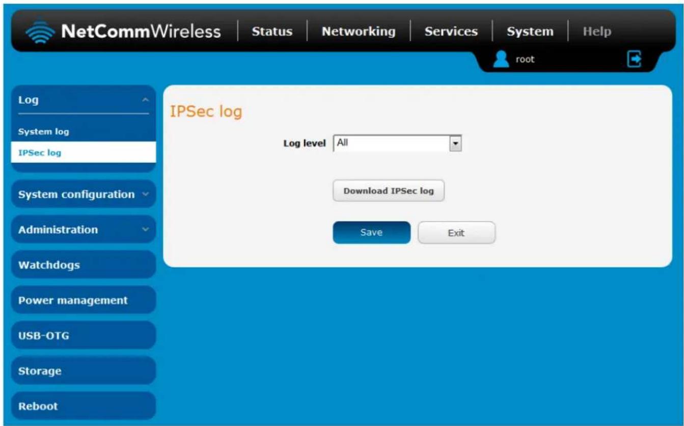
Figure 115 - IPSec log
Use the Log level drop down list to specify the type of detail you want to capture in the log and then click the Save button. When you change the logging level, any active IPSec VPN tunnels will be disconnected as a change in logging level requires the IPSec service to be restarted.
To download the IPSec log, click the Download IPSec log button and you will be prompted to save the file.
System configuration
Settings backup and restore
The settings backup and restore page is used to backup or restore the router's configuration or to reset it to factory defaults. In order to view the settings page you must be logged into the web user interface as root using the password admin. The backup / restore functions can be used to easily configure a large number of NTC-140W Series router by configuring one router with your desired settings, backing them up to a file and then restoring that file to multiple NTC-140W Series routers.
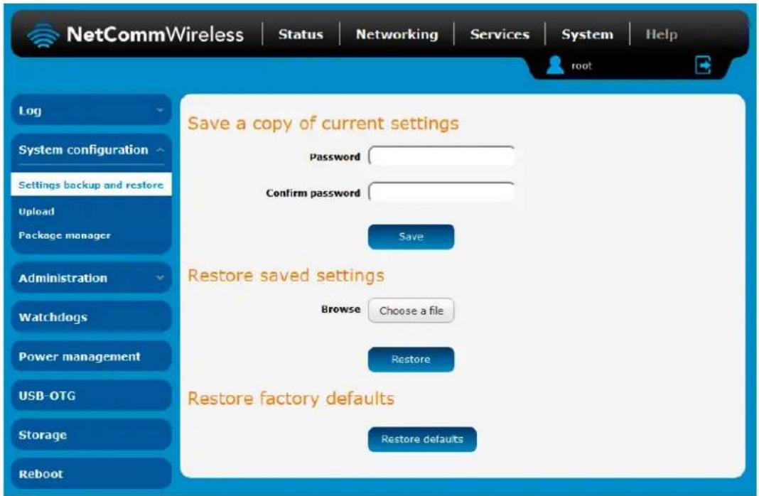
Figure 116 – Settings backup and restore
Back up your router's configuration
Log in to the web configuration interface, click on the System menu and select Settings backup and restore.
If you want to password protect your backup configuration files, enter your password in the fields under Save a copy of current settings and click on Save. If you don't want to password protect your files, just click on Save. The router will then prompt you to select a location to save the settings file.

Note: The following conditions apply:-
- It is NOT possible to edit the contents of the file downloaded; if you modify the contents of the configuration file in any way you will not be able to restore it later.
- You may change the name of the file if you wish but the filename extension must remain as ".cfg"
Restore your backup configuration
- In the web configuration interface click on the System menu and select Settings backup and restore.
- From the Restore saved settings section, click on Browse or Choose a file and select the backup configuration file on your computer.
- Click Restore to copy the settings to the new NTC-140W Series router. The router will apply these settings and inform you it will reboot - click on OK.
Restoring the router's factory default configuration
Click the Restore defaults button to restore the factory default configuration. The router asks you to confirm that you wish to restore factory default settings. If you wish to continue with the restoring of factory defaults, click OK.

Note: All current settings on the router will be lost when performing a restore of factory default settings. The device IP address will change to 192.168.1.1 and the default username root and default password admin will be configured.
Upload
To access the Upload page, click on the System menu, then System Configuration and then Upload.
The Upload page allows you to upload firmware files, HTTPS certificates or user created application packages to the NTC-140W Series router. When firmware files have been uploaded, they can also be installed from this page. PDF files, such as this user guide may also be uploaded for access on the router's help page.
For more information on application development, contact NetComm Wireless about our Software Development Kit.
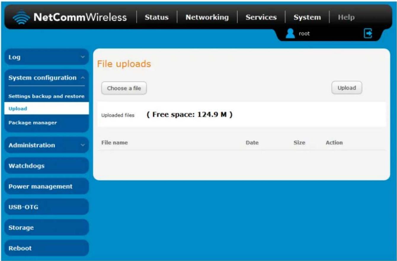
Figure 117 - Upload page
Updating the Firmware
The firmware update process involves first updating the recovery image firmware and then updating the main firmware image.

Note: In order to perform an update, you must be logged into the router with the root manager account (see the Advanced configuration section for more details).
To update the NTC-140W Series router's firmware:
- Power on the router as described in the Installing the router section.
- Log in to the router with the root user account (See the Advanced configuration section for details)
- Select the System item from the top menu bar, select the System configuration item from the menu on the left and then select the Upload menu item.
- Under the File uploads section, click the Choose a file button. Locate the recovery firmware image file on your computer and click Open. The recovery image is named ntc_140wx_x.xx.xx.x_r.cdi while the main system firmware image is named ntc_140wx_x.xx.xx.x.cdi.
- Click the Upload button. The firmware image is uploaded to the storage on the router.
| File uploads | |
| Phase | Upload |
| Percent complete | 19 % |
| Current position | 2159 / 11016KB |
| Elapsed time | 00:00:02 |
| Estimated time left | 00:00:05 |
| Estimated speed | 1822KB |
Figure 118 - File upload
6. Repeat steps 4 and 5 for the main system firmware image.
7. The uploaded firmware images are listed in the Uploaded files section. Click the Install link next to the recovery image to begin installing the recovery firmware image and then click OK on the confirmation window that appears.
| File name | Date | Size | Action | |
| ntc_140wx_x.x.xx.x.cdi | Jun 10 2014 | 32.8M | Install | Delete |
| ntc_140wx_x.x.xx.x_r.cdi | Jun 10 2014 | 13.8M | Install | Delete |
Figure 119 - Uploaded files
- The recovery firmware image is flashed and when it is complete, the router displays "The firmware update was successful" and returns to the main Upload screen.
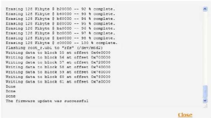
Figure 120 - Recovery firmware flash process
- Click the Install link to the right of the main firmware image you uploaded and then click OK to confirm that you want to continue with the installation.

Note: Do not remove the power when the router's LEDs are flashing as this is when the firmware update is in process.
- The installation is complete when the countdown reaches zero. The router attempts to redirect you to the Status page.
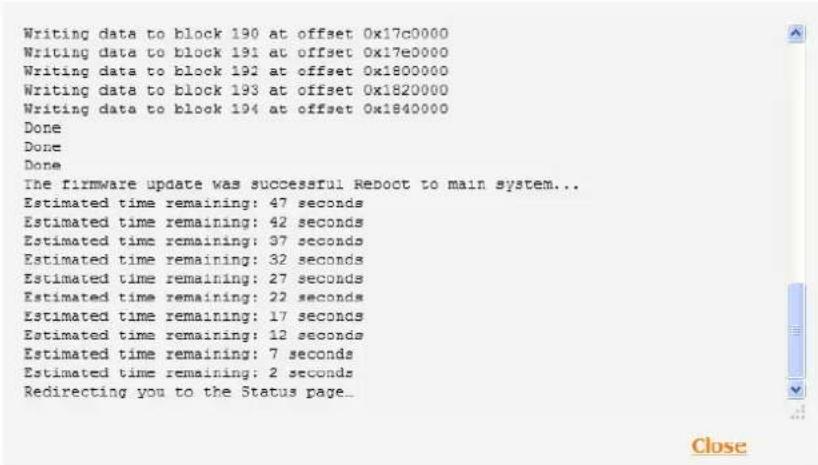
Figure 121 — Installing main firmware image
11. Hold down the reset button on the router for 15-20 seconds to reboot and restore the factory default settings of the router. See the Restoring factory default settings section for more information.
Package manager
The Package Manager page is used to provide details of any user installed packages on the router and allow them to be uninstalled. For more information on application development, contact NetComm Wireless about our Software Development Kit.
| Application name | Version | Architecture | Time installed | ||
| demonstration_app | 1.3 | arm | Friday, 6 September 2013 10:06:46 AM | Package details | Uninstall |
Figure 122 – Software applications manager
The Application name, Version number of the application, the architecture type and time of installation are all displayed. Clicking the Package details link will display a pop-up window with further details of the package.
To uninstall any software applications, click the Uninstall link.
Administration
Administration settings
To access the Administration Settings page, click on the System menu then the Administration menu on the left and then click on Administration Settings.
The Administration settings page is used to enable or disable protocols used for remote access and configure the passwords for the user accounts used to log in to the router.
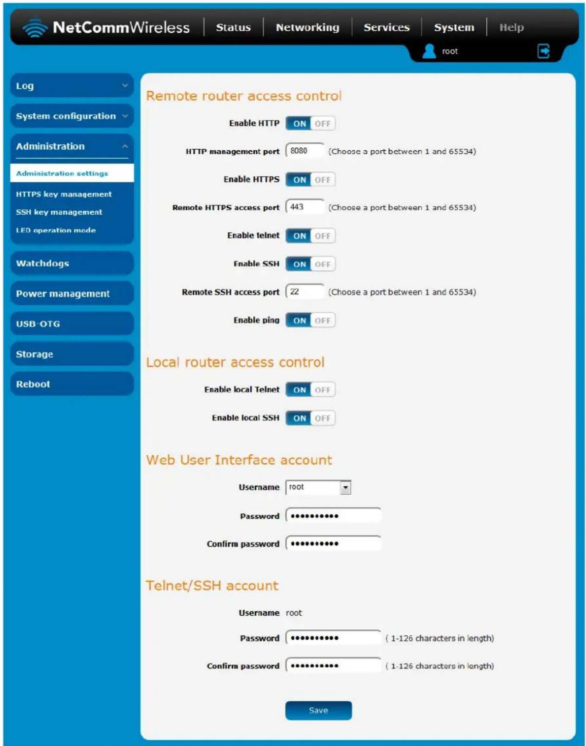
Figure 123 - Administration page
| OPTION | DEFINITION |
| Remote router access control | |
| Enable HTTP | Enable or disable remote HTTP access to the router. You can also set the port you would like remote HTTP access to be available on. |
| HTTP management port | Enter a port number between 1 and 65534 to use when accessing the router remotely. |
| Enable HTTPS | Enable or disable remote HTTPS access to the router using a secure connection. |
| Remote HTTPS access port | Enter a port number between 1 and 65534 to use when accessing the router remotely over a secure HTTPS connection. |
| Enable Telnet | Enable or disable remote telnet (command line) access to the router. |
| Enable SSH | Enable or disable Secure Shell on the router. |
| Remote SSH Access Port | Enter the port number for remote SSH access. Must be a port number between 1 and 65534. |
| Enable Ping | Enable or disable remote ping responses on the WWAN connection. |
| Local router access control (Telnet/SSH) | |
| Web User Interface account | |
| Username | Use the drop down list to select the root or admin account to change its web user interface password. |
| Password | Enter the desired web user interface password. |
| Confirm password | Re-enter the desired web user interface password. |
| Telnet/SSH account | |
| Username | Displays the Telnet/SSH.username. This may not be changed. |
| Password | Enter the desired Telnet/SSH password. |
| Confirm password | Re-enter the desired Telnet/SSH password. |
Table 38 - Administration configuration options
To access the router's configuration pages remotely:
- Open a new browser window and navigate to the WAN IP address and assigned port number of the router, for example http://123.209.130.249:8080

Note: You can find the router's WAN IP address by clicking on the "Status" menu. The WWAN IP field in the WWAN Connection Status section shows the router's WAN IP address.
- Enter the username and password to login to the router and click Log in.

Note: To perform functions like Firmware upgrade, device configuration backup and to restore and reset the router to factory defaults, you must be logged in with the root manager account.
HTTPS key management
What is HTTP Secure?
HTTP Secure or HTTPS is the use of the HTTP protocol over an SSL/TLS protocol. It is used primarily to protect against eavesdropping of communication between a web browser and the web site to which it is connected. This is especially important when you wish to have a secure connection over a public network such as the internet. HTTPS connections are secured through the use of certificates issued by trusted certificate authorities such as VeriSign. When a web browser makes a connection attempt to a secured web site, a digital certificate is sent to the browser so that it can verify the authenticity of the site using a built-in list of trusted certificate authorities.
There are two main differences between how HTTPS and HTTP connections work:
- HTTPS uses port 443 while HTTP uses port 80 by default.
- Over an HTTPS connection, all data sent and received is encrypted with SSL while over an HTTP connection, all data is sent unencrypted.
The encryption is achieved through the use of a pair of public and private keys on both sides of the connection. In cryptography, a key refers to a numerical value used by an algorithm to alter information (encrypt it), making the information secure and visible only to those who have the corresponding key to recover (decrypt) the information. The public key is used to encrypt information and can be distributed freely. The private key is used to decrypt information and must be secret by its owner.
Each NTC-140W Series router contains a self-signed digital certificate which is identical on all NTC-140W Series routers. For a greater level of security, the router also supports generating your own unique key. Additionally, you may use third party software to generate your own self-signed digital certificate or purchase a signed certificate from a trusted certificate authority and then upload those certificates to the router.
Generating your own self-signed certificate
To generate your own self-signed certificate:
- Click the System item from the top menu bar, then Administration from the side menu bar and then HTTPS key management.
- Enter the certificate details using the appropriate fields. Each field must be completed in order to generate a certificate.
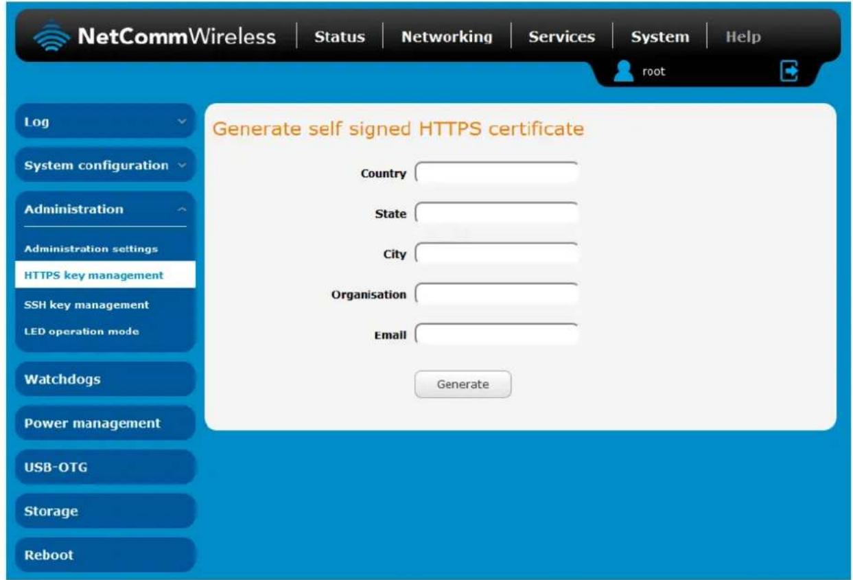
Figure 124 - Generate self signed HTTPS certificate

Note: The Country field must contain a code for the desired country from the list below.
| CODE | COUNTRY | CODE | COUNTRY | CODE | COUNTRY | CODE | COUNTRY |
| AX | Åland Islands | ER | Eritrea | LS | Lesotho | SA | Saudi Arabia |
| AD | Andorra | ES | Spain | LT | Lithuania | SB | Solomon Islands |
| AE | United Arab Emirates | ET | Ethiopia | LU | Luxembourg | SC | Seychelles |
| AF | Afghanistan | FI | Finland | LV | Latvia | SE | Sweden |
| AG | Antigua and Barbuda | FJ | Fiji | LY | Libya | SG | Singapore |
| AI | Anguilla | FK | Falkland Islands (Malvinas) | MA | Morocco | SH | St. Helena |
| AL | Albania | FM | Micronesia | MC | Monaco | SI | Slovenia |
| AM | Armenia | FO | Faroe Islands | MD | Moldova | SJ | Svalbard and Jan Mayen |
| AN | Netherlands Antilles | FR | France | ME | Montenegro | SK | Slovak Republic |
| AO | Angola | FX | France, Metropolitan | MG | Madagascar | SL | Sierra Leone |
| AQ | Antarctica | GA | Gabon | MH | Marshall Islands | SM | San Marino |
| AR | Argentina | GB | Great Britain (UK) | MK | Macedonia | SN | Senegal |
| AS | American Samoa | GD | Grenada | ML | Mali | SR | Suriname |
| AT | Austria | GE | Georgia | MM | Myanmar | ST | Sao Tome and Principe |
| AU | Australia | GF | French Guiana | MN | Mongolia | SU | USSR (former) |
| AW | Aruba | CG | Guernsey | MO | Macau | SV | El Salvador |
| AZ | Azerbaijan | GH | Ghana | MP | Northern Mariana | SZ | Swaziland |
| BA | Bosnia and Herzegovina | GI | Gibraltar | MQ | Martinique | TC | Turks and Caicos Islands |
| BB | Barbados | GL | Greenland | MR | Mauritania | TD | Chad |
| BD | Bangladesh | GM | Gambia | MS | Montserrat | TF | French Southern Territories |
| BE | Belgium | GN | Guinea | MT | Malta | TG | Togo |
| BF | Burkina Faso | GP | Guadeloupe | MU | Mauritius | TH | Thailand |
| BG | Bulgaria | GQ | Equatorial Guinea | MV | Maldives | TJ | Tajikistan |
| BH | Bahrain | GR | Greece | MW | Malawi | TK | Tokelau |
| BI | Burundi | GS | S. Georgia and S. Sandwich | MX | Mexico | TM | Turkmenistan |
| BJ | Benin | GT | Guatemala | MY | Malaysia | TN | Tunisia |
| BM | Bermuda | GU | Guam | MZ | Mozambique | TO | Tonga |
| BN | Brunei Darussalam | GW | Guinea-Bissau | NA | Namibia | TP | East Timor |
| BO | Bolivia | GY | Guyana | NC | New Caledonia | TR | Turkey |
| BR | Brazil | HK | Hong Kong | NE | Niger | TT | Trinidad and Tobago |
| BS | Bahamas | HM | Heard and McDonald Islands | NF | Norfolk Island | TV | Tuvalu |
| BT | Bhutan | HN | Honduras | NG | Nigeria | TW | Taiwan |
| BV | Bouvet Island | HR | Croatia (Hrvatska) | NI | Nicaragua | TZ | Tanzania |
| BW | Botswana | HT | Haiti | NL | Netherlands | UA | Ukraine |
| BZ | Belize | HU | Hungary | NO | Norway | UG | Uganda |
| CA | Canada | ID | Indonesia | NP | Nepal | UM | US Minor Outlying Islands |
| CC | Cocos (Koeling) Islands | IE | Ireland | NR | Nauru | US | United States |
| CF | Central African Republic | IL | Israel | NT | Neutral Zone | UY | Uruguay |
| CH | Switzerland | IM | Isle of Man | NU | Niue | UZ | Uzbekistan |
| CI | Cote D'Ivoire (Ivory | IN | India | NZ | New Zealand | VA | Vatican City State (Holy See) |
| CK | Cook Islands | IO | British Indian Ocean Territory | OM | Oman | VC | Saint Vincent and the |
| CL | Chile | IS | Iceland | PA | Panama | VE | Venezuela |
| CM | Cameroon | IT | Italy | PE | Peru | VG | Virgin Islands (British) |
| CN | China | JE | Jersey | PF | French Polynesia | VI | Virgin Islands (U.S.) |
| CO | Colombia | JM | Jamaica | PG | Papua New Guinea | VN | Viet Nam |
| CR | Costa Rica | JO | Jordan | PH | Philippines | VU | Vanuatu |
| CS | Czechoslovakia (former) | JP | Japan | PK | Pakistan | WF | Wallis and Futuna Islands |
| CV | Cape Verde | KE | Kenya | PL | Poland | WS | Samoa |
| CX | Christmas Island | KG | Kyrgyzstan | PM | St. Pierre and | YE | Yemen |
| CY | Cyprus | KH | Cambodia | PN | Pitcairn | YT | Mayotte |
| CZ | Czech Republic | KI | Kiribati | PR | Puerto Rico | ZA | South Africa |
| DE | Germany | KM | Comoros | PS | Palestinian Territory | ZM | Zambia |
| DJ | Djibouti | KN | Saint Kitts and Nevis | PT | Portugal | COM | US Commercial |
| DK | Denmark | KR | Korea (South) | PW | Palau | EDU | US Educational |
| DM | Dominica | KW | Kuwait | PY | Paraguay | GOV | US Government |
| DO | Dominican Republic | KY | Cayman Islands | QA | Qatar | INT | International |
| DZ | Algeria | KZ | Kazakhstan | RE | Reunion | MIL | US Military |
| EC | Ecuador | LA | Laos | RO | Romania | NET | Network |
| EE | Estonia | LC | Saint Lucia | RS | Serbia | ORG | Non-Profit Organization |
| EG | Egypt | LI | Liechtenstein | RU | Russian Federation | ARPA | Old style Arpanet |
| EH | Western Sahara | LK | Sri Lanka | RW | Rwanda |
- When you have entered all the required details, press the Generate button. The certificate takes several minutes to generate. When the certificate has been generated, you are informed that it has been successfully generated and installed. The web server on the router restarts and you are logged out of the router. Click OK to be taken back to the login screen.
A new certificate has successfully been generated and installed. The web server is restarting now. Please login again to proceed.
OK
Figure 125 - New certificate successfully generated message
SSH key management
Secure Shell (SSH) is UNIX-based command interface and network protocol used to gain secure access to a remote computer, execute commands on a remote machine or to transfer files between machines. It was designed as a replacement for Telnet and other insecure remote shell protocols which send information, including passwords, as plain text.
SSH uses RSA public key cryptography for both connection and authentication. Two common ways of using SSH are:
Use automatically generated public-private key pairs to encrypt the network connection and then use password authentication to log on.
Use a manually generated public-private key pair to perform the authentication and allow users or programs to log in without using a password.
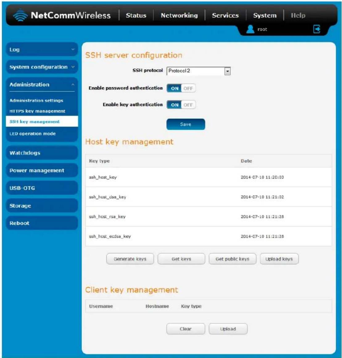
Figure 126 - SSH Server Configuration
SSH Server Configuration
To configure the SSH server settings:
- Use the SSH Protocol drop down list to select the protocol that you want to use. Protocol 2 is more recent and is considered more secure.
- Select the types of authentication you want to use by clicking the Enable password authentication and Enable key authentication toggle keys on or off. Note that you may have both authentication methods on but you may not turn them both off.
- Click the Save button to confirm your settings.
Host key management
SSH keys provide a means of identification using public key cryptography and challenge response authentication. This means that a secure connection can be established without transmitting a password, thereby greatly reducing the threat of someone eavesdropping and guessing the correct credentials.
SSH Keys always come in pairs with one being a public key and the other a private key. The public key may be shared with any server to which you want to connect. When a connection request is made, the server uses the public key to encrypt a challenge (a coded message) to which the correct response must be given. Only the private key can decrypt this challenge and produce the correct response. For this reason, the private key should not be shared with those who you do not wish to give authorization.
The Host key management section displays the current public keys on the router and their date and timestamp. These public keys are provided in different formats, including DSA, RSA and ECDSA. Each format has advantages and disadvantages in terms of signature generation speed, validation speed and encryption/decryption speed. There are also compatibility concerns to consider with older clients when using ECDSA, for example.
Host key management
| Key type | Date |
| ssh_host_key | 2014-07-04 11:48:58 |
| ssh_host_dsa_key | 2014-07-04 11:49:15 |
| ssh_host_rsa_key | 2014-07-04 11:49:23 |
| ssh_host_ecdsa_key | 2014-07-04 11:49:23 |
Generating new keys
The complete set of keys can be re-generated by selecting the Generate keys button. This key generation process takes approximately 30 seconds to complete.
Downloading keys
The Get keys button allows you to download the complete set of public and private keys while the Get public keys button will download only the set of public keys.
Uploading your own key files
Click the Upload keys button to upload your own public key to the router.
Client key management
The Client Key Management section is used for uploading the public key file of clients. To upload a client public key, click the Upload button, browse to the file and click Open.
Client key management
| Username | Hostname | Key type |
| ClearUpload |
When the file is uploaded, it is examined for validity. If the key file is not a valid public key, it will not be uploaded.
LED operation mode
The 8 front LED indicators may be turned off after a timeout period for aesthetic or power saving reasons. To access the LED Operation Mode page, click the System menu, then Administration on the left and finally select LED Operation Mode.
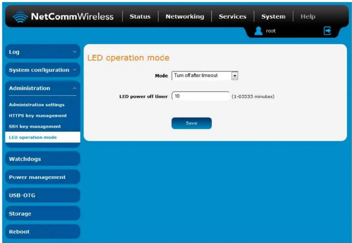
Figure 127 - LED Operation Mode
The Mode drop down list sets the operation mode of the LEDs on the front panel of the router. To set the lights to operate at all times, set this to Always on. To set the lights to turn off after a specified period, select Turn off after timeout. When configured to turn off after timeout, use the LED power off timer field to specify the time in minutes to wait before turning off the LED indicators. The LED Power Off Timer must be an integer between 1 and 65535.
The wait period begins from the time the Save button is clicked. When the wait period expires, the LEDs will turn off. If the router is rebooted, the LED power off timer is reset. The router will boot up and wait for the configured time before turning off again.
Watchdogs
To access the Watchdogs page, click the System menu item, then select the Watchdogs menu item on the left.
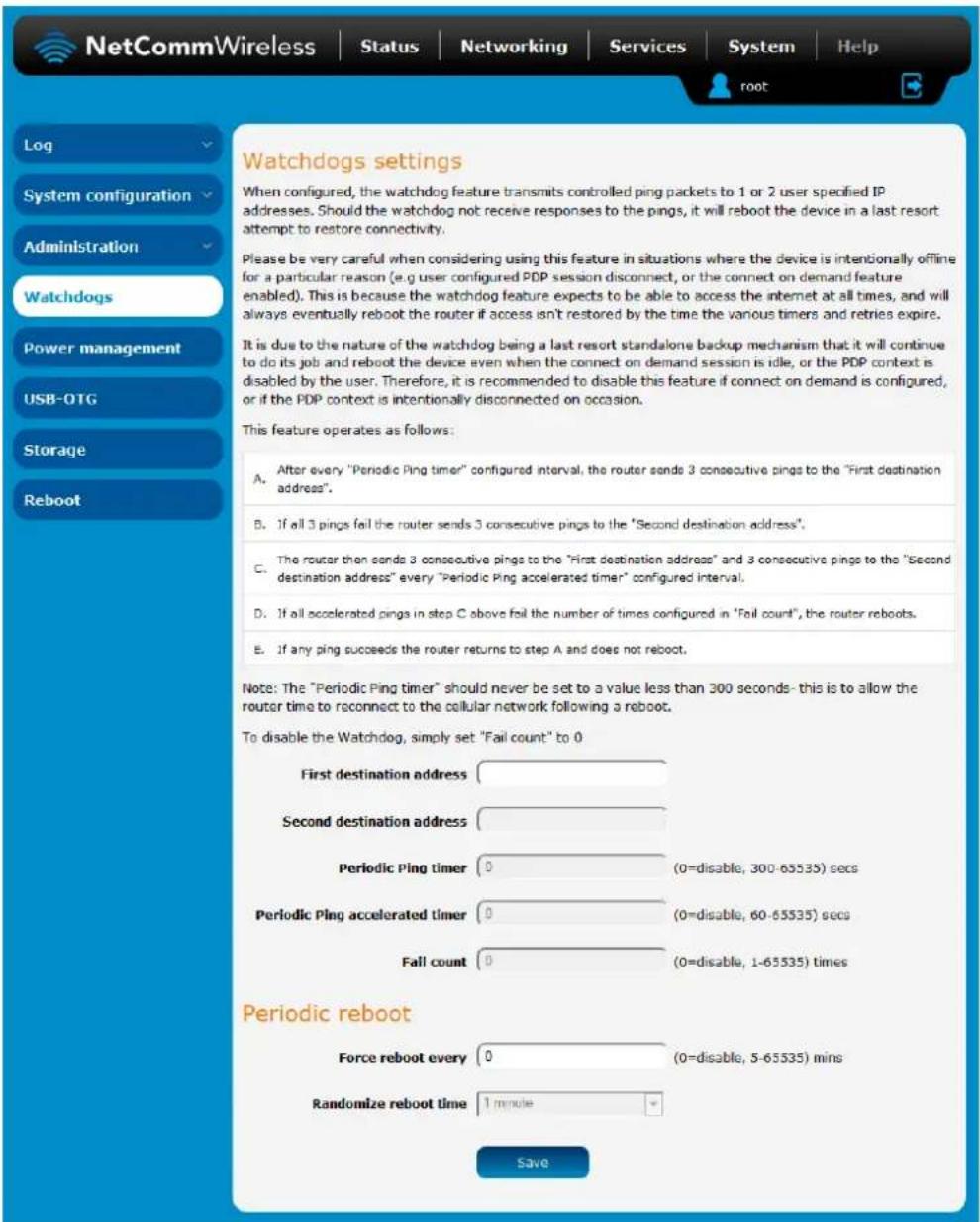
Figure 128 - Watchdogs Settings
Watchdogs are features which monitor the router for anomalies and restart the router if an anomaly occurs preventing its normal operation. When configured, the watchdogs feature transmits controlled ping packets to 1 or 2 user specified IP addresses to confirm an active connection. If the watchdog does not receive responses to the pings after a specified number of failures, it will reboot the device in a last resort attempt to restore connectivity.
We recommend using caution when implementing this feature in situations where the device is intentionally offline for a particular reason, for example, when Connect-on-demand has been enabled. This is because the watchdog expects to be able to access the internet at all times, and will always eventually reboot the router if access isn't restored by the time the various timers expire and the fail count is reached.
It is due to the nature of the watchdog being a last resort standalone backup mechanism that it will continue to do its job and reboot the device even when the Connect-on-demand session is idle, or the PDP context is disabled by the user. Therefore, we recommended that you disable this feature if Connect-on-demand is configured or if the PDP context is intentionally disconnected on occasion.
The watchdog works as follows:
a) The router sends 3 consecutive pings to the first destination address at the interval specified in the Periodic Ping timer field.
b) If all 3 pings to the first destination address fail, the router sends 3 consecutive pings to the second destination address at the Periodic Ping timer interval.
c) If all 3 pings to the second destination address fail, the router sends 3 pings to the first destination address using the Periodic Ping accelerated timer interval.
d) If all 3 accelerated pings to the first destination address fail, the router sends 3 pings to the second destination address at the Periodic Ping accelerated timer interval.
e) If all 3 accelerated pings to the second destination address fail, the router registers this as a fail and returns to step C.
When the number of failures reaches the number configured in the Fail count field, the router reboots. If any ping succeeds, the router returns to step A and does not reboot.

Note: The Periodic Ping timer should not be set to a value of less than 300 seconds to allow the router time to reconnect to the cellular network following a reboot.
To disable the periodic ping reset monitor, set Fail count to 0.
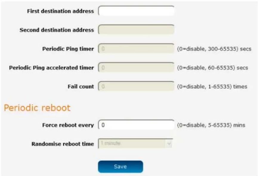
Figure 129 – Ping watchdog settings
Configuring Periodic Ping settings
The Periodic Ping settings configure the router to transmit controlled ping packets to 2 specified IP addresses. If the router does not receive responses to the pings, the router will reboot.
To configure the ping watchdog:
- In the First destination address field, enter a website address or IP address to which the router should send the first round of ping requests.
- In the Second destination address field, enter a website address or IP address to which the router should send the second round of ping requests.
- In the Periodic Ping timer field, enter an integer between 300 and 65535 for the number of seconds the router should wait between ping attempts. Setting this to 0 disables the ping watchdog function.
- In the Periodic Ping accelerated timer field, enter an integer between 60 and 65535 for the number of seconds the router should wait between accelerated ping attempts, i.e. pings to the second destination address. Setting this to 0 disables the ping watchdog function
- In the Fail count field, enter an integer between 1 and 65535 for the number of times an accelerated ping should fail before the router reboots. Setting this to 0 disables the ping watchdog function.
Disabling the Periodic Ping reset function
To disable the Periodic Ping reset function, set Fail count to 0.

Note: The traffic generated by the periodic ping feature is usually counted as chargeable data usage. Please keep this in mind when selecting how often to ping.
Configuring a Periodic reboot
The router can be configured to automatically reboot after a period of time specified in minutes. While this is not necessary, it does ensure that in the case of remote installations, the router will reboot if some anomaly occurs.
- In the Force reboot every field, enter the time in minutes between forced reboots. The default value is 0 which disables the Periodic reboot function. The minimum period between reboots is 5 minutes while the maximum value is 65535 minutes.
- If you have configured a forced reboot time, you can use the Randomise reboot time drop down list to select a random reboot timer. Randomising the reboot time is useful for preventing a large number of devices from rebooting simultaneously and flooding the network with connection attempts. When configured, the router waits for the configured Force reboot every time and then reboots after waiting for a random period that is less than or equal to the Randomise reboot time setting.
- Click the Save button to save the settings.

Note: The randomise reboot time is not persistent across reboots; each time the router is due to reboot, it randomly selects a time less than or equal to the Randomise reboot time.
Power management
The Power management page provides you with an overview of the power profiles and the ability to configure them. Up to five power profiles may be configured and all of them may be active simultaneously. The Status column indicates whether the profile is active, while the Sleep mode and Wake mode columns summarise the method used to sleep or wake the modem.

Note: When configuring multiple power profiles, be careful so that they do not overlap or conflict with one another, for example, configuring a schedule which wakes up the unit when another profile has it scheduled to be in low power mode.
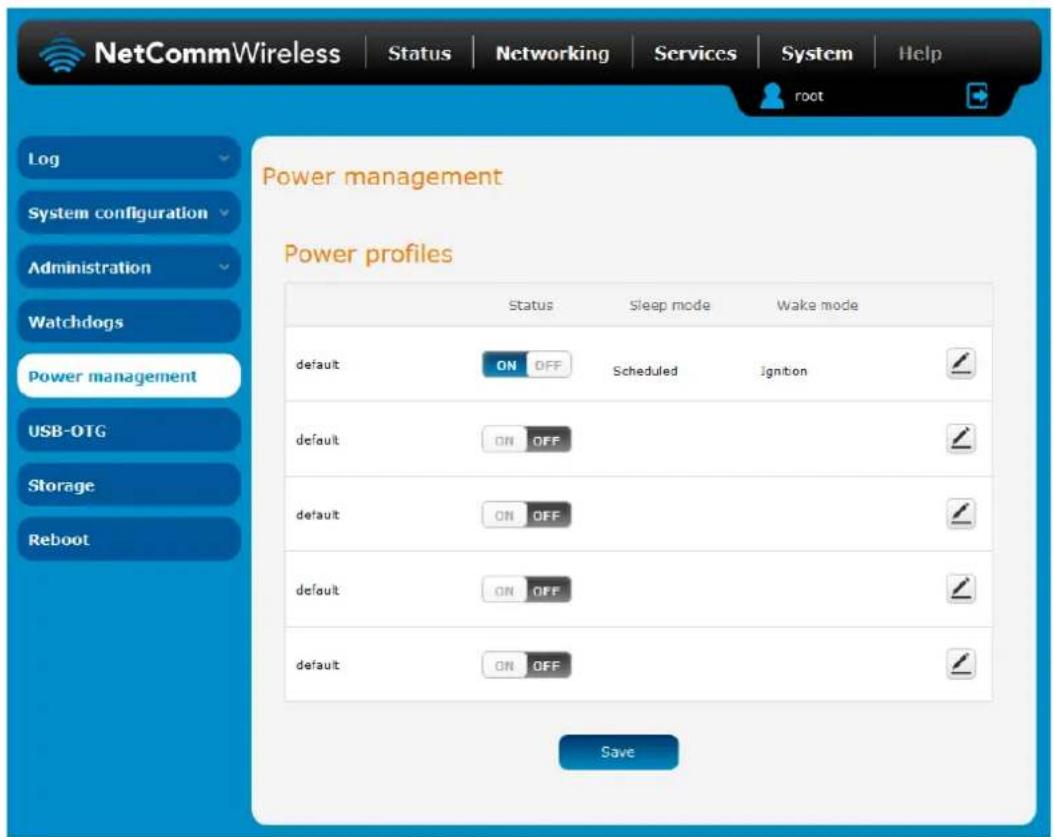
Figure 130 · Power management
To edit a power profile, click the Edit icon of the appropriate profile.
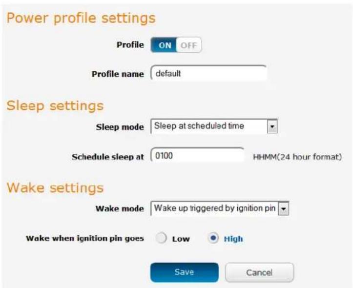
Figure 131 - Power management - Power profile settings
Sleep settings
Use the Sleep mode drop down list to select a condition under which the router should enter the sleep state.
Sleep after timer
When this mode is selected, the router will enter the sleep state after the number of minutes specified in the Sleep after field, regardless of the state of the ignition pin.

Figure 132 - Sleep after timer
Sleep at scheduled time
When this mode is selected, the router goes to sleep at the time specified in the Schedule sleep at field, regardless of the state of the ignition pin. Enter the time in 24 hour format without the semi-colon.

Figure 133 - Sleep at scheduled time
Sleep triggered by ignition pin
This mode sets the router to enter sleep state when the signal on the ignition pin reaches the specified value.
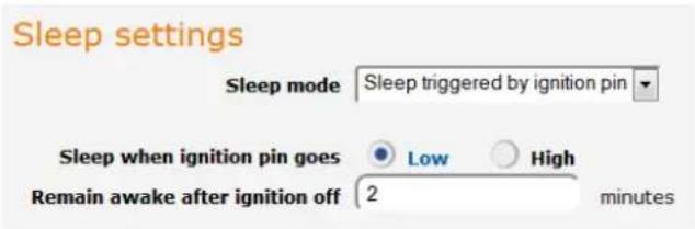
Figure 134 - Sleep triggered by ignition pin
Use the Sleep when ignition pin goes setting to select Low or High. By default, this is set to Low. Additionally, the router will stay on for the number of minutes specified in the Remain awake after ignition off field. The minimum value for this field is 2 minutes with the maximum being 255 minutes.
Wake settings
Use the Wake mode drop down list to select a condition under which the router should return from the sleep state.
Wake triggered by ignition pin
This mode sets the router to wake up when the signal on the ignition pin reaches the specified value.
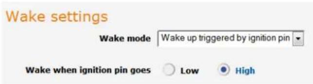
Figure 135 - Wake up triggered by ignition pin
Use the Wake up when ignition pin goes setting to select Low or High. By default, this is set to High.
Wake up at scheduled time
When this mode is selected, the router wakes up at the time specified in the Schedule wake up at field, regardless of the state of the ignition pin. Enter the time in 24 hour format without the semi-colon.
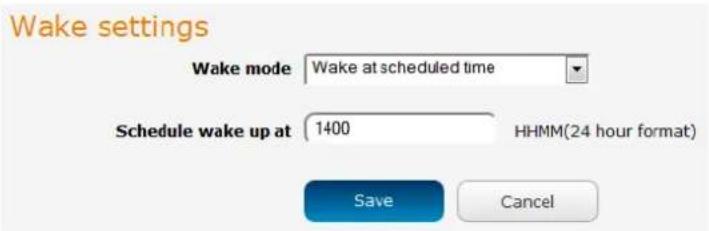
Figure 136 - Wake up at scheduled time
Enter the time in seconds to wait before returning from sleep state in the Always wake up after field. A setting of 0 means that the router will automatically wake from sleep state immediately.
USB-OTG
The USB-OTG page displays the current status of the USB port, i.e. whether it is in Device mode or Host mode. By default, Automatic mode is set to ON, allowing the router to intelligently choose the correct mode. If you wish to manually override this selection, you can turn off Automatic mode and set Host or Device mode yourself.
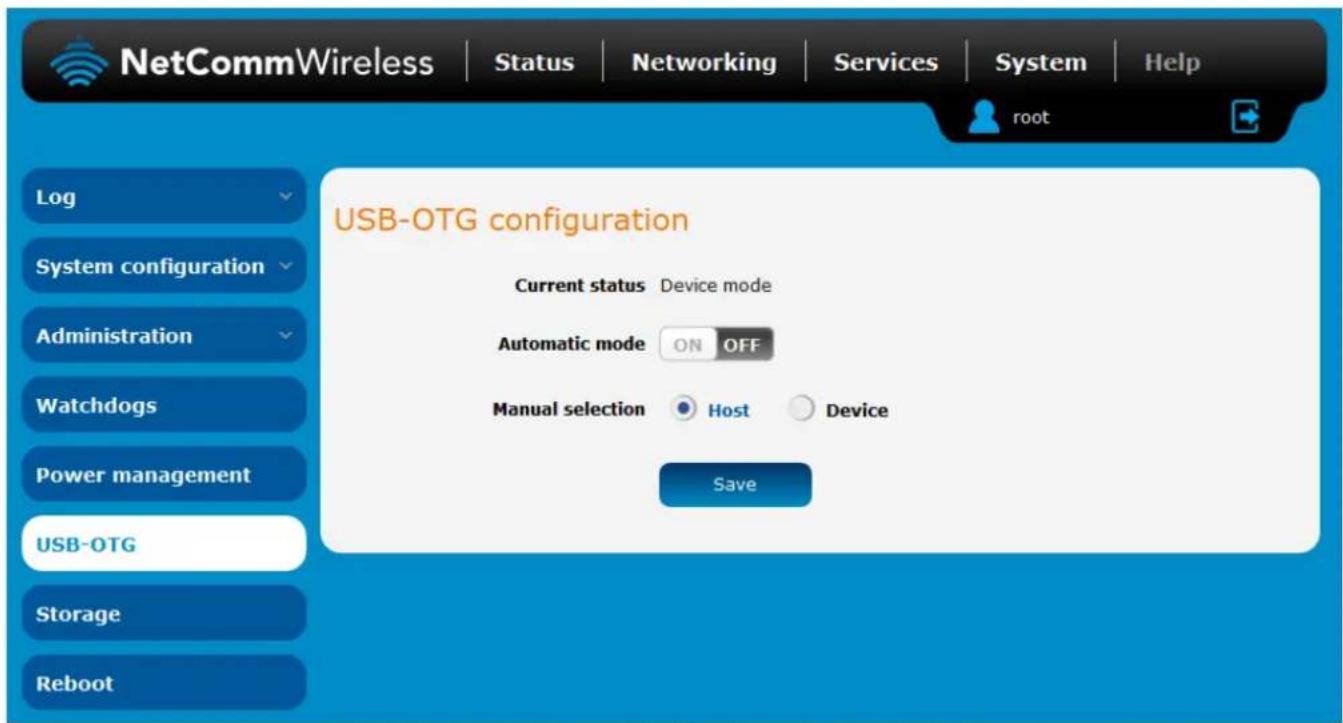
Figure 137 - USB-OTG configuration
Storage
The Storage page provides configuration options with relation to USB and SD storage devices.
Storage device list
The Storage devices list displays any connected storage devices and summarises the type, file system, size, used and available space on each device. Additionally, an eject button is provided to unmount the storage device so you can safely remove it.
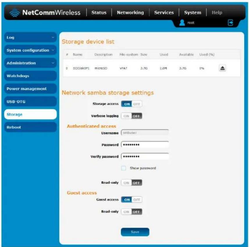
Figure 138 - Storage
Network Samba storage settings
Storage devices connected to the router can be shared using the Samba protocol. The table below describes the configuration options for the Network Samba storage settings.
| ITEM | DEFINITION |
| Storage access | Turns the Samba sharing function on or off. |
| Verbose logging | When turned on, this provides additional logging data in the system log. This should generally only be used when debugging to avoid generating excessively long logs. |
| Authenticated access | |
| Username | The username to be used for authenticated access to the storage device. This is configured as 'smbuser' and cannot be changed. |
| Password | The password to be used for authenticated access to the storage device. |
| Verify password | The password to be used for authenticated access to the storage device. |
| Show password | Displays the passwords in the authenticated access fields. |
| Read-only | When turned on, this provides read-only access to the files on the connected storage device(s). When read-only access for authenticated accounts is turned on, the guest access read-only option is hidden and guests are permitted read-only access also. |
| Guest access | |
| Guest access | Enables or disables guest access to the storage device. |
| Read-only | When turned on, this provides read-only access to the files on the connected storage device(s) for guest users. If the authenticated account has Read-only enabled then this option is not available and read-only access is automatically granted to guest users. |
Table 39 - Network Samba storage settings
Reboot
The reboot option in the System section performs a soft reboot of the router. This can be useful if you have made configuration changes you want to implement.
To reboot the router:
- Click the System menu item from the top menu bar.
- Click the Reboot button from the menu on the left side of the screen.
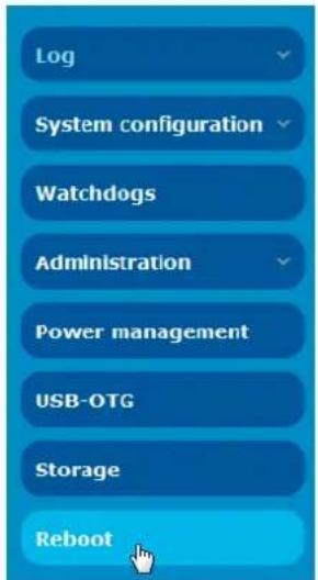
Figure 139 - Reboot menu option
- The router displays a warning that you are about to perform a reboot. If you wish to proceed, click the Reboot button then click OK on the confirmation window which appears.
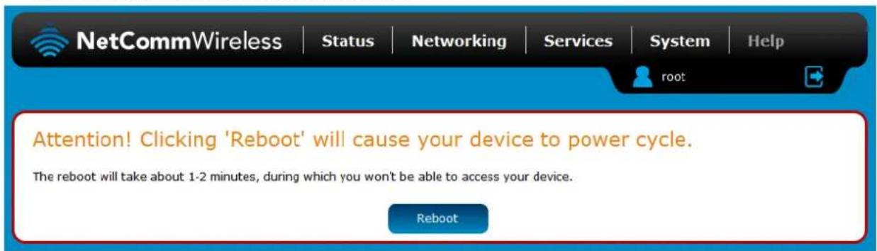
Figure 140 - Reboot confirmation

Note: It can take up to 2 minutes for the router to reboot.
Logging out
To log out of the router, click the icon at the top right corner of the web user interface.
Appendix A: Tables
Table 1 - Document Revision History ......2
Table 2 - Device Dimensions....7
Table 3 - LED Indicators 8
Table 4 - Signal strength LED descriptions....9
Table 5 - Ethernet port LED indicators description....9
Table 6 – Interfaces....10
Table 7 - Locking power block pin outs....14
Table 8 - Management account login details – Root manager ....15
Table 9 - Management account login details – Admin manager....15
Table 10 - Status page item details....18
Table 11 - Data connection item details ....20
Table 12 - Connect on demand - Connect and disconnect timers descriptions....26
Table 13 - Wireless Configuration - Basic Configuration Items....37
Table 14 - Wireless Settings – SSID and Security Settings ....38
Table 15 - Wireless Settings - Advanced Configuration Items....39
Table 16 – Wireless hotspot settings....42
Table 17 - Wireless settings – Client Configuration ....43
Table 18 - Ethernet group configuration items....45
Table 19 - Ethernet WAN configuration options....46
Table 20 - Failover configuration - Hardware link monitoring....48
Table 21 - Failover configuration - Ping monitoring....48
Table 22 - Current MAC / IP / Port filtering rules in effect....58
Table 23 - IPSec Configuration Items....61
Table 24 - Mobile Station Based Assisted GPS configuration options....85
Table 25 - Odometer configuration options....86
Table 26 - IO configuration options....88
Table 27 - IO pin modes 89
Table 28 - SMS Setup Settings....91
Table 29 - Inbox/Outbox icons....93
Table 30 - SMS Diagnostic Command Syntax....98
Table 31 - List of basic SMS diagnostic commands....99
Table 32 - List of get/set commands....101
Table 33 - List of basic SMS diagnostics RDB variables....101
Table 34 - Network types returned by get plmnscan SMS command....102
Table 35 - Operator status codes returned by get plmnscan SMS command....102
Table 36 - SMS diagnostics example commands....105
Table 37 - System log detail levels....107
Table 38 - Administration configuration options....114
Table 39 - Network Samba storage settings ....128
Table 40 - LAN Management Default Settings....131
Table 41 - Web Interface Default Settings....131
Table 42 - Telnet Access ......131
Table 43 - RJ-45 connector pin outs....138
Table 44 - Technical Specifications of the NTC-140W-01 and NTC-140W-02 Series routers....147
Appendix B: Default Settings
The following tables list the default settings for the NTC-140W Series router.
| LAN (MANAGEMENT) | |
| Static IP Address: | 192.168.1.1 |
| Subnet Mask: | 255.255.255.0 |
| Default Gateway: | 192.168.1.1 |
Table 40 - LAN Management Default Settings
| ADMIN MANAGER ACCOUNT | ROOT MANAGER ACCOUNT | ||
| Username: | admin | Username: | root |
| Password: | admin | Password: | admin |
Table 41 - Web Interface Default Settings

Note: The admin manager account allows you to manage all settings of the router except functions such as firmware upgrade, device configuration backup and restore and reset to factory default settings, which are privileged only to the root manager account.
| NTC-140W SERIES ROUTER TELNET ACCESS | |
| Username: | root |
| Password: | admin |
Table 42 - Telnet Access
Restoring factory default settings
Restoring factory defaults will reset the NTC-140W Series router to its factory default configuration. You may encounter a situation where you need to restore the factory defaults on your NTC-140W Series router such as:
You have lost your username and password and are unable to login to the web configuration page;
You are asked to perform a factory reset by support staff.
There are two methods you can use to restore factory default settings on your NTC-140W Series router:
Using the web-based user interface
Using the reset button on the interface panel of the router
Using the web-based user interface
To restore your router to its factory default settings, please follow these steps:
- Open a browser window and navigate to the IP address of the router (default address is http://192.168.1.1). Login to the router using root as the User Name and admin as the password.
- Click the System item from the top menu bar, then System configuration on the left menu and then click Settings backup and restore.
- Under the Restore factory defaults section, click the Restore defaults button. The router asks you to confirm that you wish to restore factory defaults. Click OK to continue. The router sets all settings to default. Click OK again to reboot the router.
- When the Power light returns to a steady red, the reset is complete. The default settings are now restored.
Using the reset button on the interface panel of the router
Use a pen to depress the Reset button on the device for 15-20 seconds. The router will restore the factory default settings and reboot.
When you have reset your NTC-140W Series router to its default settings you will be able to access the device's configuration web interface using http://192.168.1.1 with username admin or root and password admin.
Appendix C: Recovery mode
The NTC-140W Series Router features two independent operating systems, each with its own file systems. These two systems are referred to as 'Main' and 'Recovery'. It is always possible to use one in order to restore the other in the event that one system becomes damaged or corrupted (such as during a firmware upgrade failure). The recovery console provides limited functionality and is typically used to restore the main firmware image in the case of a problem.
Accessing recovery mode
Both systems have web interfaces that can be used to manipulate the other inactive system. The NTC-140W Series Router starts up by default in the Main system mode, however the router may be triggered to start in recovery mode if desired.
To start the router in recovery mode:
- Press and hold the physical reset button on the interface panel of the router for 5 to 15 seconds. When the LEDs on the front panel change to amber and countdown in a sequence, release the reset button. The router then boots into recovery mode.
- In your browser, navigate to http://192.168.1.1. The router's recovery mode is hardcoded to use this address regardless of the IP address that was configured in the main system. The router's recovery console is displayed.
NetComm Cellular Router Recovery Console
| Status | Log | Application Installer | Settings | Reboot | |
| Status | |||||
| System Information | |||||
| System Up time | 00:01:19 | ||||
| Router Version | Hardware: 1.0 Software: XXXXXXXX | ||||
| Serial Number | 164199131700017 | ||||
| Trigger | button | ||||
| LAN | |||||
| IP | 192.168.1.1 / 255.255.255.0 | ||||
| MAC Address | 00:60:64:B2:D4:22 | ||||
| Ethernet Port Status | |||||
| LAN: √ | Up / 100.0 Mbps / FDX | ||||
Figure 141 - Recovery console
Status
The status page provides basic information such as the system up time, hardware and software router versions, the router's serial number, the method used to trigger the recovery mode, the IP and MAC address of the router and the status of the Ethernet port.
NetComm Cellular Router Recovery Console
| Status | Log | Application Installer | Settings | Reboot |
| Status | ||||
| System Information | ||||
| System Up time | 00:01:19 | |||
| Router Version | Hardware: 1.0 Software: XXXXXXXX | |||
| Serial Number | 164199131700017 | |||
| Trigger | button | |||
| LAN | ||||
| IP | 192.168.1.1 / 255.255.255.0 | |||
| MAC Address | 00:60:64:B2:D4:22 | |||
| Ethernet Port Status | ||||
| LAN: √ | Up / 100.0 Mbps /FDX | |||
Figure 142 - Recovery mode - Status
Log
The log page displays the system log which is useful in troubleshooting problems which may have led to the router booting up in recovery mode. The only functionality provided here is the ability to clear the system log, filter by log level and downloading of the log file.
| Status | Log | Application Installer | Settings | Reboot | |
| Log File Display Level Debug Page 1 of 14 Clear Log File | |||||
| Date & Time | Machine | Level | Process | Message | |
| Jan 1 00:01:15 | nto_140wx | daemon.info | dnsmasq-dhcp[379] | DHCPINFORM(eth0) 192.168.1.129 00:02:19:0e:3a:19 | |
| Jan 1 00:01:11 | nto_140wx | daemon.warn | dnsmasq-dhcp[379] | Ignoring domain corp.netcomm.com.au for DHCP host name NTCWKS0072 | |
| Jan 1 00:01:11 | nto_140wx | daemon.info | dnsmasq-dhcp[379] | DHCPACK(eth0) 192.168.1.129 00:02:19:0e:3a:19 NTCWK50072 | |
| Jan 1 00:01:11 | nto_140wx | daemon.info | dnsmasq-dhcp[379] | DHCPREQUEST(eth0) 192.168.1.129 00:02:19:0e:3a:19 | |
| Jan 1 00:01:11 | nto_140wx | daemon.info | dnsmasq-dhcp[379] | DHCPOFFER(eth0) 192.168.1.129 00:02:19:0e:3a:19 | |
| Jan 1 00:01:11 | nto_140wx | daemon.warn | dnsmasq[379] | overflow: 5 log entries lost | |
| Jan 1 00:00:05 | nto_140wx | daemon.info | dnsmasq[379] | started, version 2.57 cachesize 150 | |
| Jan 1 00:00:40 | nto_140wx | user.info | disp[452] | [disp] boot period time-out - sec=40 sec | |
| Jan 1 00:00:10 | nto_140wx | user.debug | kernel | [ 18.902219] eth0; no IPv8 routers present | |
| Jan 1 00:00:06 | nto_140wx | user.info | kernel | [ 8.189219] ADDRCONF(NETDEV_CHANGE): eth0; link becomes ready | |
| Jan 1 00:00:08 | nto_140wx | user.info | kernel | [ 8.184459] PHY: 0:01 - Link is Up - 10:Half | |
| Jan 1 00:00:06 | nto_140wx | user.info | disp[452] | force to redraw all LEDs | |
| Jan 1 00:00:06 | nto_140wx | user.info | disp[452] | [led-off] resetting dim timer (sec) - current timer=0 | |
| Jan 1 00:00:06 | nto_140wx | user.info | disp[452] | [led-off] set dim timer - timer=0 sec | |
| Jan 1 00:00:06 | nto_140wx | user.info | disp[452] | reset all LEDs to solid off | |
| Jan 1 00:00:06 | nto_140wx | user.en | disp[452] | set priority (prior=-20) | |
| Jan 1 00:00:06 | nto_140wx | user.info | disp[452] | sysbg LOG_INFO | |
| Jan 1 00:00:06 | nto_140wx | user.en | disp[452] | sysbg LOG_ERR | |
| Jan 1 00:00:06 | nto_140wx | user.en | disp[452] | ================ | |
| Jan 1 00:00:06 | nto_140wx | user.en | disp[452] | loglevel check | |
| Jan 1 00:00:06 | nto_140wx | user.en | disp[452] | ================ | |
| Jan 1 00:00:06 | nto_140wx | user.info | kernel | [ 8.187114] PHY: 0:01 - Link is Down | |
| Jan 1 00:00:06 | nto_140wx | user.info | kernel | [ 8.188968] PHY: 0:01 - Link is Up - 0/Half | |
Download Log File
Figure 143 - Recovery mode - Log
Application Installer
The Application installer is designed to upload and install main firmware images, upload recovery firmware images, custom applications and HTTPS certificates. Use the Browse button to select a file to be uploaded to the router. When it has been selected, press the Upload button. The file is sent to the router and when the transfer is complete, the file appears in the Uploaded files list. From the Uploaded files list, you are able to either Install or Delete a file.
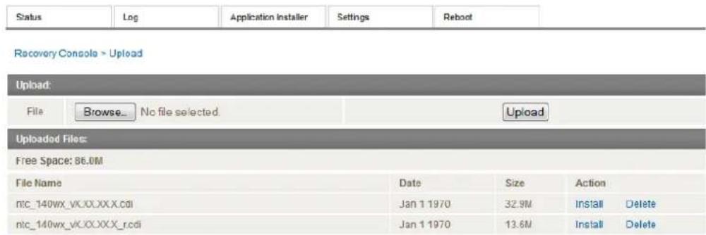
Figure 144 - Recovery mode - Application Installer
Settings
The settings page provides the option of restoring the router to factory default settings. Click the Restore button to set the router back to the original factory settings.

Figure 145 - Recovery mode – Settings
Reboot
The reboot page allows you to reboot the router when you have finished using recovery mode. When rebooting the router from recovery mode, the router boots into the main firmware image unless there is some fault preventing it from doing so, in which case the recovery console will be loaded.
Click the Reboot button to reboot the router to the main firmware image.
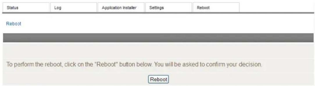
Figure 146 - Recovery mode - Reboot
Appendix D: HTTPS - Uploading a self-signed certificate
If you have your own self-signed certificate or one purchased elsewhere and signed by a Certificate Authority, you can upload it to the NTC-140W Series router using the Upload page.

Note: Your key and certificate files must be named server.key and server.crt respectively otherwise they will not work.
To upload your certificate:
- Click on the System item from the top menu bar. From the side menu bar, select System Configuration and then Upload. The file upload screen is displayed.
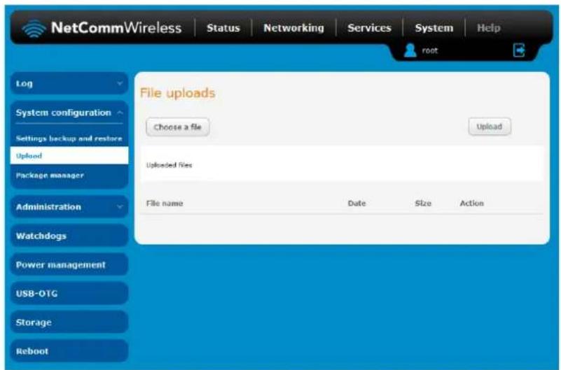
Figure 147 - Upload page
- Click the Choose a File button and locate your server certificate file and click Open.
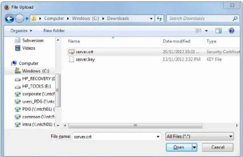
Figure 148 - Browse for server.crt
- Click the Upload button to begin uploading it to the router. The file appears in the list of files stored on the router.
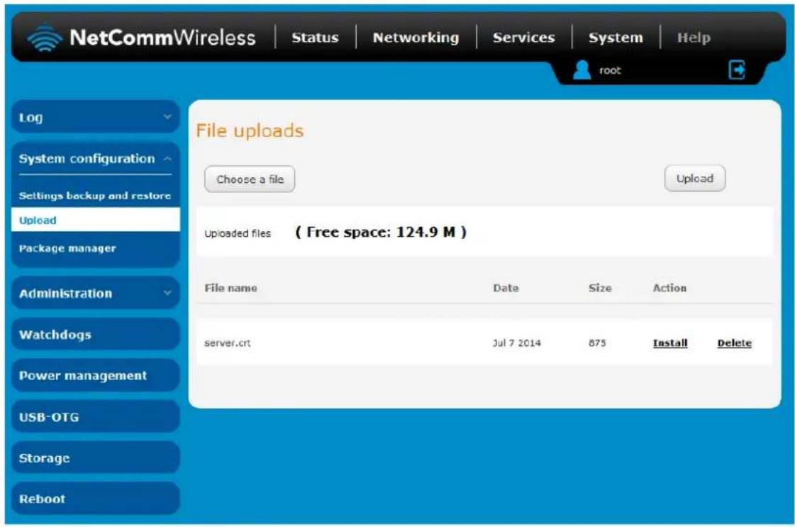
Figure 149 - Server certificate file uploaded
- Repeat steps 2 and 3 for the server key file.
- Click the Install link next to the server.crt file then click OK on the prompt that is displayed. The certificate file is installed. Repeat this for the key file. When each file is installed it is removed from the list of stored files.
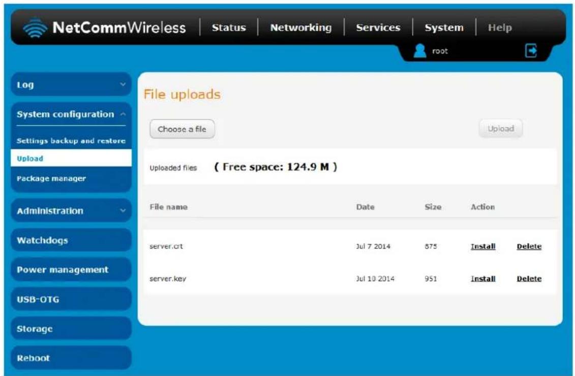
Figure 150 - Installing the server.crt file
Appendix E: RJ-45 connectors
The RJ-45 connectors provide an interface for a data connection and for device input power using the pin layout shown below.

Pin: 8 1
Figure 151 - The RJ-45 connector
| PIN | COLOUR | SIGNAL (10/100) | SIGNAL (1000) |
| 1 | White/Orange stripe | Rx + DC + | +BI_DA |
| 2 | Orange Solid | Rx - DC + | -BI_DA |
| 3 | White/Green stripe | Tx + DC - | +BI_DB |
| 4 | Blue solid | unused | +BI_DC |
| 5 | White/Blue stripe | unused | -BI_DC |
| 6 | Green solid | Tx - DC - | -BI_DB |
| 7 | White/Brown stripe | unused | +BI_DD |
| 8 | Brown solid | unused | -BI_DD |
Table 43 - RJ-45 connector pin outs
Appendix G: Input/Output
Overview
The NTC-140W series router is equipped with a 2 x 2 Molex connector providing a multipurpose input and output terminal as well as a dedicated ignition input. The I/O terminal may be independently configured for various functions, including:
NAMUR (EN 60947-5-6 / IEC 60947-5-6) compatible sensor input
Proximity sensor input for use with contact closure (open/closed) type of sensors (PIR sensors, door/window sensors for security applications) with the input tamper detection possible (four states detected: open, closed, short and break) by the use of external resistors
Analogue 0V to 30V input
Digital input (the I/O voltage measured by the Analogue input and the software making a decision about the input state) with the threshold levels configurable in software
Open collector output.
Hardware Interface
The interface of the input/output terminals are based on the circuit diagram below
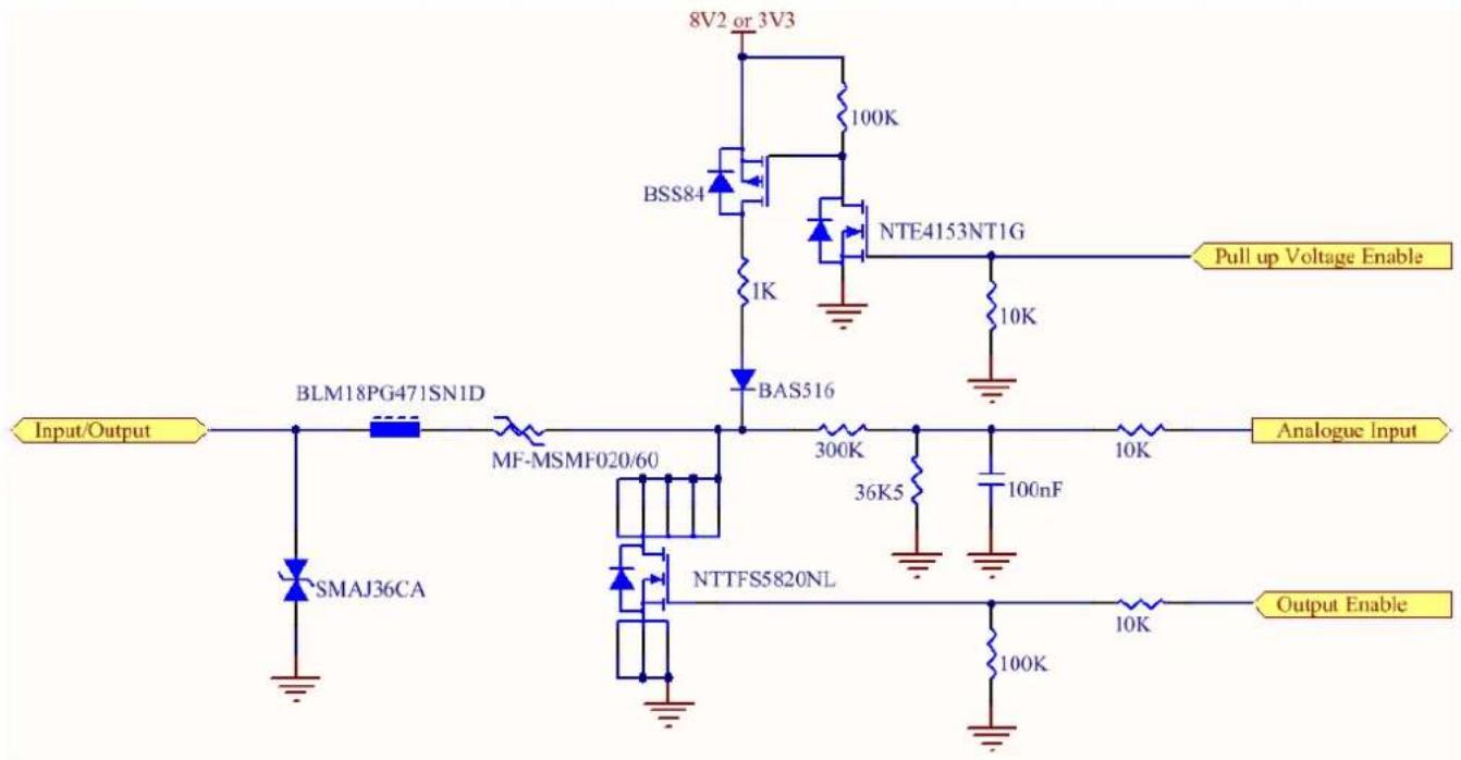
The Input/Output label is the physical connection to the outside world. There are protection devices and resistor dividers to condition the signal prior to it going into the processor. The three labels to the right are the interface to the processor. Output Enable activates the Transistor which provides an open collector (ground) output and can sink 200mA at 23C. It is protected by a resettable fuse and transient protection diode. If used with the pull up resistor, which can be activated by the Pull up Voltage Enable pin, then you can have a High or Low output rather than open drain. The resistor can be pulled up to 3V3 for Cmos compatible output or 8.2V by software. The Analogue Input pin can read values from 0V to 30V. It is divided by a resistor network to read appropriate levels in the processor. Depending on the sensor type used, the pull up resistor can be switched on or off. If using the NAMUR sensor configuration the pull up will be activated to 8V2 by default.
Wiring Examples
The following examples are shown as a guide as to what can be achieved by the I/O features. It is up to the system integrator to have enough knowledge about the interface to be able to achieve the required results.

Note: NetComm Wireless does not offer any further advice on the external wiring requirements or wiring to particular sensors, and will not be responsible for any damage to the unit or any other device used in conjunction with it. Using outputs to control high voltage equipment can be dangerous. The integrator must be a qualified electrician if dealing with mains voltages controlled by this unit.
Open Collector Output driving a relay
Any output can be configured to control a relay. This is an example where the transistor will supply the ground terminal of the solenoid. External voltage is supplied to the other side of the solenoid.
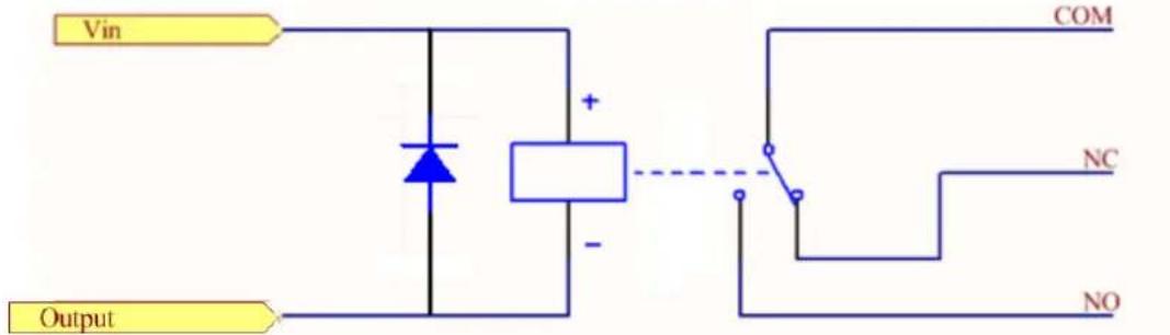
Relay wiring depends on the requirement of the device being controlled.
Logic level Output
An output can be used with the pull up resistor to provide a logic level output which would be suitable to control an external digital device.
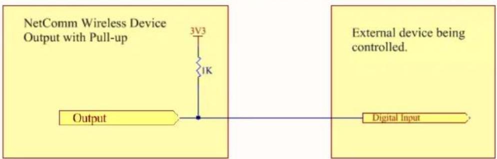
flowchart
graph LR
    A["NetComm Wireless Device Output with Pull-up"] --> B["3V3"]
    B --> C["1K"]
    C --> D["Output"]
    E["External device being controlled."] --> F["Digital Input"]
LED Output
An LED can be controlled by simply providing an open collector ground to an externally powered LED Resistor value and Voltage will need to suit the LED type used. Alternatively an LED can be powered using 8V2 via 1K resistor. The suitability of the LED will need to be investigated.
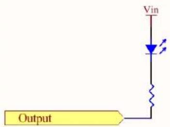
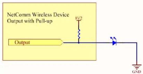
Digital inputs
There are several ways to connect a digital input. A digital input can be anything from a simple switch to a digital waveform or pulses. The unit will read the voltage in as an analogue input and the software will decode it in a certain way depending on your configuration.
Below is a contact closure type input, which is detecting an Earth. Pull up is activated for this to work.
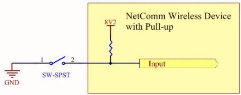
The following input detects an input going high. The turn on/off threshold can be set in the software.


flowchart
graph LR
    A["Input 0V - 30V"] --> B["Digital pulses"]
    B --> C["Input"]
NAMUR Sensor
A NAMUR sensor is a range of sensors which conform to the EN 60947-5-6 / IEC 60947-5-6 standards. They basically have two states which are reflected by the amount of current running through a sense resistor.
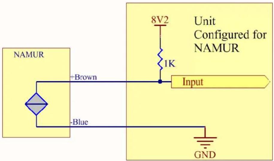
Analogue Sensor with Voltage output
There are various analogue sensors that connect directly to the unit which can provide a voltage output. These would require an external power source which may or may not be the same as the unit itself. The voltage range they provide can be between 0V and 30V. Some common sensor output ranges include 0V to 10V. The pull up resistor is not activated in this case.
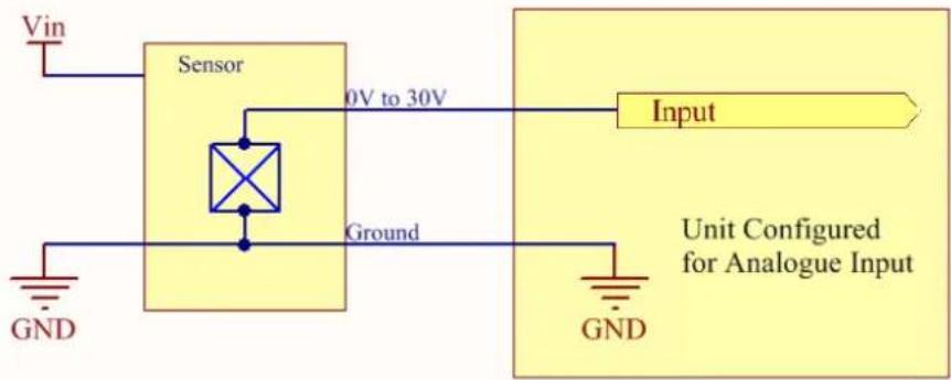
Analogue Sensor with 4 to 20mA output
Another common type of sensor type is the 4-20mA current loop sensor. It provides a known current through a fixed resistor, usually 250 ohms thus producing a voltage of 0V to 5V at the input. The sensor would require an external power source which may or may not be the same as the unit itself. It will also require an external resistor. The internal pull up resistor is not activated.
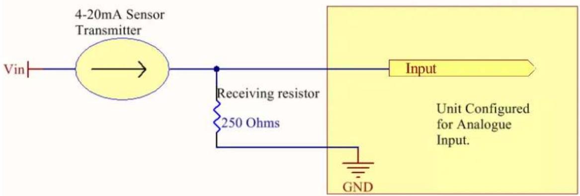
Analogue Sensor with Thermistor
Some sensors work by changing resistance due to a change, such as temperature, light etc. These may be wired up to an external or internal power source and the resistance can be read into the analogue signal. This will require some software calibration like scaling or offset to map the voltage received to the sensor resistor value. An example below shows the internal pull-up voltage and 1K resistor activated. The voltage received depends on the combination of resistors and the value of the resistance of the sensor itself.
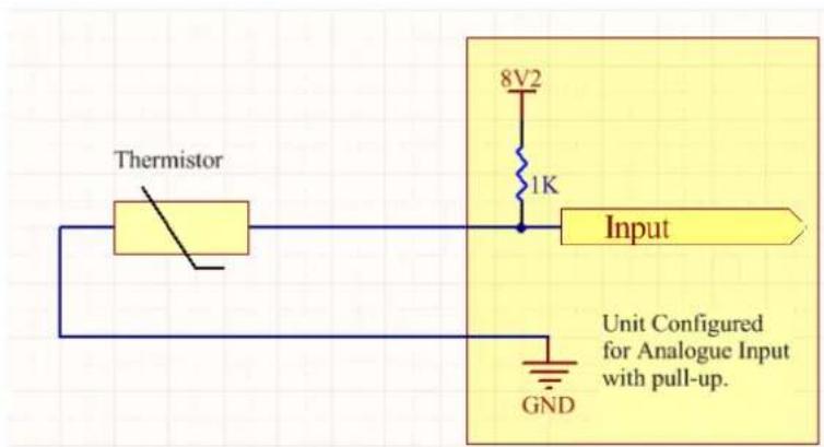
System Example – Solar powered Router with battery backup
The previous examples of wiring can be used to come up with a system. The following test case is an example of how the I/O's can be used to enhance a simple router setup.
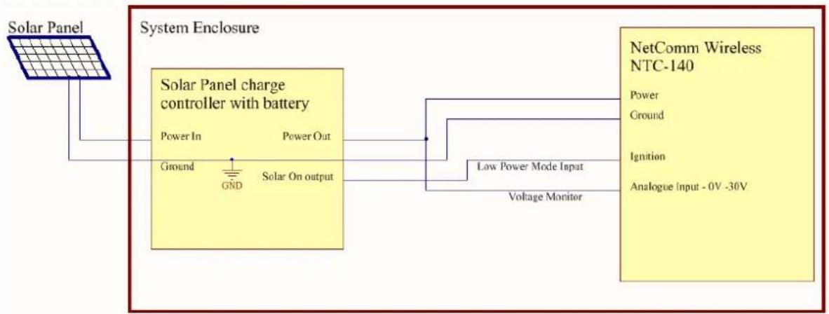
flowchart
graph LR
    A["Solar Panel"] --> B["System Enclosure"]
    B --> C["Solar Panel charge controller with battery"]
    C --> D["Power In"]
    C --> E["Power Out"]
    C --> F["Ground"]
    C --> G["GND"]
    C --> H["Solar On output"]
    C --> I["Low Power Mode Input"]
    I --> J["Voltage Monitor"]
    J --> K["NetComm Wireless NTC-140"]
    K --> L["Power"]
    K --> M["Ground"]
    K --> N["Ignition"]
    K --> O["Analogue Input - 0V -30V"]
Appendix H: Obtaining a list of RDB variables
The RDB is a database of variables that contain settings on the router. You can retrieve (get) and set the values of these variables through the command-line or via SMS Diagnostics. To access a full list of the RDB variables, follow these steps:
- Log in to the web user interface as described in the Advanced configuration section of this guide.
- Click the System menu at the top of the screen, then select the Administration menu on the left. Finally, select the Administration settings menu item.
- Click the Enable Telnet toggle key so that it is in the ON position.
Enable Telnet


- Under the Telnet/SSH account section, enter a telnet password and then re-enter it in the Confirm password field.
- Click the Save button at the bottom of the screen.
- Open a terminal client such as PuTTY and telnet to the router using its IP address.
- At the login prompt, type root and press Enter. At the password prompt, enter the password that you configured in step 4.
- At the root prompt, enter the command rdb dump | more. This will display a list of every rdb variable on the router one page at a time.
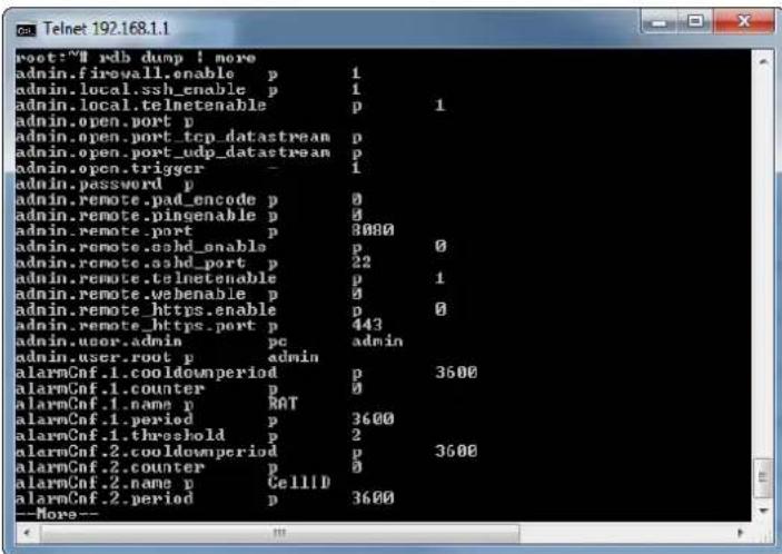

Note: Omitting the | more parameter will dump a complete list without pagination. For easier access, some terminal clients such as PuTTY have the ability to log all telnet output to a text file.
Appendix I: Using USB devices and MicroSD cards
The NTC-140W Series router features a Mini USB 2.0 OTG port capable of supplying 0.5A to connected devices and a microSD card slot allowing additional storage. The Mini USB port supports both USB storage devices as well as certain USB accessories, including USB-to-Ethernet adapters and USB-to-Serial cables.
Accessing USB/SD card storage devices
When a USB storage device or microSD card is inserted, the router automatically mounts the storage. To access storage devices:
Windows
- Open Windows Explorer.
- In the address bar, type in the network address of the router (\my.router or \192.168.1.1 by default), and press Enter. The storage devices are labelled Disk A, Disk B or Disk C.
Mac OS
- In Mac OS, open a Finder window.
- Select Go -> Connect to Server.
- Enter the server address smb://my.router or smb://192.168.1.1
- Select the volumes you want to mount. Storage devices are labelled Disk A, Disk B or Disk C.
Linux / Smartphones
You can use any Samba client on Linux and Smartphones to access the connected storage devices by navigating to "my.router" or "192.168.1.1" in your chosen Samba client.
Host and Device mode
The USB port automatically detects whether to run in host or device mode. When in host mode, the router automatically mounts USB storage devices. When in device mode, the router supports Ethernet over USB. It is also possible to configure the USB Ethernet port as a WAN port.
Technical Data
The following tables list the hardware specifications of the NTC-140W Series routers.
| COMPONENT | NTC-140W-01 | NTC-140W-02 |
| Memory | 256MByte Flash memory storage (~120MB available on board space for user storage) | |
| Operating System | Embedded Linux & Software Development Kit (SDK) | |
| Cellular bands | LTE:Band 2 (1900 MHz)Band 4 (AWS) (1700 / 2100 MHz)Band 5 (850 MHz)Band 13 (700 MHz)Band 17 (700 MHz)Band 25 (1900 MHz G Block)CDMA (EVDO Release 0 and EVDO Release A):BC0 (Cellular 800 MHz)BC1 (PCS 1900 MHz)BC10 (Secondary 800 MHz)UMTS/HSDPA/HSUPA/HSPA+/DC-HSPA+:Band 1 (2100 MHz)Band 2 (1900 MHz)Band 4 (AWS 1700/2100 MHz)Band 5 (850 MHz)Band 8 (900 MHz)GSM/GPRS/EDGE:GSM 850 (850 MHz)EGSM 900 (900 MHz)DCS 1800 (1800 MHz)PCS 1900 (1900 MHz) | LTE:Band 1 (2100 MHz)Band 3 (1800 MHz)Band 7 (2600 MHz)Band 8 (900 MHz)Band 20 (800 MHz)UMTS/HSDPA/HSUPA/HSPA+/DC-HSPA+:Band 1 (2100 MHz)Band 2 (1900 MHz)Band 5 (850 MHz)Band 6 (800 MHz)Band 8 (900 MHz)GSM/GPRS/EDGE:GSM 850 (850 MHz)EGSM 900 (900 MHz)DCS 1800 (1800 MHz)PCS 1900 (1900 MHz)CNSS:GPS: 1575.42 MHzGLONASS: 1602 MHz |
| Maximum Data Throughput / LTE Radio interface | LTE data rates:Category 3Downlink: 100 Mbps (20 MHz bandwidth), 50 Mbps (10 MHz bandwidth)Uplink: 50 Mbps (20 MHz bandwidth), 25 Mbps (10 MHz bandwidth)CDMA EVDO Release 0 and EVDO Release ACDMA IS 856 (1xEV DO Release A):Up to 3.1 Mbps forward channelUp to 1.8 Mbps reverse channelCDMA IS-2000Up to 153 kbps, simultaneous forward and reverse channelCircuit-switched data bearers up to 14.4 kbpsUMTS (WCDMA)/HSDPA/HISUPA/HSPA+/DC-HSPA+HSPA+ ratesDownlink: Up to 42 Mbps (category 24)Uplink: Up to 5.76 Mbps (category 6)GSM/GPRS/EDGEEDGE throughput up to 236 kbps | LTE data rates:Category 3Downlink:100 Mbps (20 MHz bandwidth)50 Mbps (10 MHz bandwidth)Uplink:50 Mbps (20 MHz bandwidth)25 Mbps (10 MHz bandwidth)UMTS (WCDMA)/HSDPA/HISUPA/HSPA+/DC-HSPA+HSPA+ ratesDownlink: Up to 42 Mbps (category 24)Uplink: Up to 5.76 Mbps (category 6)GSM/GPRS/EDGEEDGE throughput up to 236 kbps |
| Connectivity | 2 x 10/100/1000 Base-T Ethernet RJ45 ports with Auto MDIXMicro USB 2.0 OTG interface with 0.5A supply capability1 x multipurpose I/O pin | |
| SIM Card Reader | 1 x Lockable SIM Card Tray Reader, Push to Release | |
| Antenna connectors | 2x SMA connectors for Cellular (1x Main and 1x RX Diversity)1x SMA connector for GPS2x Reverse-SMA WLAN (MIMO) | |
| LED Indicators | Tri-colour (Red/Amber/Green) LEDs. Power, WLAN, Mobile Broadband, Service Type and Signal Strength indicators | |
| GPS | Embedded GPS receiver (1575.42MHz)Active antenna voltage: 3.05VMaximum current: 50mATracking sensitivity under open sky: -159dBmAcquisition sensitivity under open sky: -149dBmCold start sensitivity: -145dBmTime to first fix (TTFF): Cold 25s, Warm 10s, Hot 3sShort circuit protectionSupports NMEA-0183 (v2.3)Redirect NMEA stream to serial for forward over IPOdometer reading available via Web-UI, CLI and SDK | |
| Operating Temperature | Operating Temperature Range (Class A): -30°C to +70°COperating Temperature Range (Class B)*: -40°C to +85°C*with performance deviation | |
| Power Input | Power input and I/O via 4 way Molex mini-fit connectorDC Power (8 - 40V DC)1x dedicated ignition input on 4 way connectorMinimum power input rating of 6W via 4 way mini-fit connector. Recommended power input 12V 1.5A.Vehicle compatible protection on DC Input Jack. (Designed to ISO7637 standard) | |
| Dimensions & Weight | 143mm (L) x 107mm (W) x 34mm (D) / ~235g | |
| Regulatory Compliance | FCC, IC, Designed to ISO7637 standard | CE, GCF, RCM, Designed to ISO7637 standard. |
Table 44 - Technical Specifications of the NTC-140W-01 and NTC-140W-02 Series routers
Safety and product care
RF Exposure
Your device contains a transmitter and a receiver. When it is on, it receives and transmits RF energy. When you communicate with your device, the system handling your connection controls the power level at which your device transmits.
This device meets the government's requirements for exposure to radio waves.
This device is designed and manufactured not to exceed the emission limits for exposure to radio frequency (RF) energy set by the Federal Communications Commission of the U.S. Government.
This equipment complies with radio frequency (RF) exposure limits adopted by the Federal Communications Commission for an uncontrolled environment. This equipment should be installed and operated with minimum distance 20 cm between the radiator & your body.
Any optional external antenna used for this transmitter must be installed to provide a separation distance of at least 20 cm from all persons and must not be co-located or operated in conjunction with any other antenna or transmitter. Please consult the health and safety guide of the chosen antenna for specific body separation guidelines as a greater distance of separation may be required for high-gain antennas.
Any external antenna gain must meet RF exposure and maximum radiated output power limits of the applicable rule section. The maximum antenna gain for this device as reported to the FCC is: dBi (MHz) and dBi (MHz).
CE Approval
This device has been tested to and conforms to the regulatory requirements of the European Union and attained CE Marking. The CE Mark is a conformity marking consisting of the letters "CE." The CE Mark applies to the products regulated by the central European health, safety and environmental protection legislation. The CE Mark is obligatory for products it applies to: the manufacturer affixes the marking in order to be allowed to sell their product in the European market.
The wireless device is approved to be used in the member states of the EU. NetComm Wireless declares that the wireless device is in compliance with the essential requirements and other relevant provisions of the Radio and Telecommunications Terminal Equipment Directive 1999/5/EC (R&TTE Directive). Compliance with this directive implies conformity to the following European Norms – N 60950 – Product Safety, EN 301 489 EMC, EN301511 GSM RF, EN301908 UMTS RF, EN 62311 SAR Technical requirement for radio equipment. A notified body has determined that this device has properly demonstrated that the requirements of the directive have been met and has issued a favourable certificate of expert opinion. As such the device will bear the notified body number 0682 after the CE mark.
The CE Marking is not a quality mark. Foremost, it refers to the safety rather than to the quality of the product. Secondly, CE Marking is mandatory for the product it applies to whereas most quality markings are voluntary.
Marking: The product shall bear the CE mark, the notified body number(s) as depicted to the right. CE 0682
NOTE: To comply with the RF exposure requirements, this equipment must be operated with a minimum of 20 cm separation from the user.
This is a regulatory requirement and applies to all 3G capable devices meeting standard regulatory compliance such as the compliance standards listed above.
FCC Statement
FCC compliance
Federal Communications Commission Notice (United States): Before a wireless device model is available for sale to the public, it must be tested and certified to the FCC that it does not exceed the limit established by the government-adopted requirement for safe exposure.
FCC regulations
This device complies with part 15 of the FCC Rules. Operation is subject to the following two conditions: (1) This device may not cause harmful interference, and (2) this device must accept any interference received, including interference that may cause undesired operation.
This device has been tested and found to comply with the limits for a Class B digital device, pursuant to Part 15 of the FCC Rules. These limits are designed to provide reasonable protection against harmful interference in a residential installation. This equipment generates, uses and can radiate radio frequency energy and, if not installed and used in accordance with the instructions, may cause harmful interference to radio communications. However, there is no guarantee that interference will not occur in a particular installation. If this equipment does cause harmful interference to radio or television reception, which can be determined by turning the equipment off and on, the user is encouraged to try to correct the interference by one or more of the following measures:
Reorient or relocate the receiving antenna.
Increase the separation between the equipment and receiver.
Connect the equipment into an outlet on a circuit different from that to which the receiver is connected.
Consult the dealer or an experienced radio/TV technician for help.
Changes or modifications not expressly approved by the party responsible for compliance could void the user's authority to operate the equipment.
IC regulations
CAN ICES-3(B)/NMB-3(B)
This device complies with Industry Canada licence-exempt RSS standard(s). Operation is subject to the following two conditions:
(1) this device may not cause interference, and
(2) this device must accept any interference, including interference that may cause undesired operation of the device.
This Class B digital apparatus complies with Canadian CAN ICES-3 (B)/NMB-3(B).
This equipment complies with IC RSS-102 radiation exposure limits set forth for an uncontrolled environment. This equipment should be installed and operated with minimum distance 20cm between the radiator and users body.
Electrical safety
Accessories
Only use approved accessories.
Do not connect with incompatible products or accessories.
Connection to a car
Seek professional advice when connecting a device interface to the vehicle electrical system.
Distraction
Operating machinery
Full attention must be given to operating the machinery in order to reduce the risk of an accident.
Product handling
You alone are responsible for how you use your device and any consequences of its use.
You must always switch off your device wherever the use of a mobile phone is prohibited. Do not use the device without the clip-on covers attached, and do not remove or change the covers while using the device. Use of your device is subject to safety measures designed to protect users and their environment.
Always treat your device and its accessories with care and keep it in a clean and dust-free place.
Do not expose your device or its accessories to open flames or lit tobacco products.
Do not expose your device or its accessories to liquid, moisture or high humidity.
Do not drop, throw or try to bend your device or its accessories.
Do not use harsh chemicals, cleaning solvents, or aerosols to clean the device or its accessories.
Do not paint your device or its accessories.
Do not attempt to disassemble your device or its accessories, only authorised personnel must do so.
Do not use or install this product in extremely hot or cold areas. Ensure that the device is installed in an area where the temperature is within the supported operating temperature range (-20°C to 70°C)
Do not use your device in an enclosed environment or where heat dissipation is poor. Prolonged use in such space may cause excessive heat and raise ambient temperature, which will lead to automatic shutdown of your device or the disconnection of the mobile network connection for your safety. To use your device normally again after such shutdown, cool it in a well-ventilated place before turning it on.
Please check local regulations for disposal of electronic products.
Do not operate the device where ventilation is restricted
Installation and configuration should be performed by trained personnel only.
Do not use or install this product near water to avoid fire or shock hazard. Avoid exposing the equipment to rain or damp areas.
Arrange power and Ethernet cables in a manner such that they are not likely to be stepped on or have items placed on them.
Ensure that the voltage and rated current of the power source match the requirements of the device. Do not connect the device to an inappropriate power source.
Small children
Do not leave your device and its accessories within the reach of small children or allow them to play with it.
They could hurt themselves or others, or could accidentally damage the device.
Your device contains small parts with sharp edges that may cause an injury or which could become detached and create a choking hazard.
Emergency & other situations requiring continuous connectivity
This device, like any wireless device, operates using radio signals, which cannot guarantee connection in all conditions. Therefore, you must never rely solely on any wireless device for emergency communications or otherwise use the device in situations where the interruption of data connectivity could lead to death, personal injury, property damage, data loss, or other loss.
Device heating
Your device may become warm during normal use.
Faulty and damaged products
Do not attempt to disassemble the device or its accessories.
Only qualified personnel must service or repair the device or its accessories.
If your device or its accessories have been submerged in water punctured or subjected to a severe fall, do not use until they have been checked at an authorised service centre.
Interference
Care must be taken when using the device in close proximity to personal medical devices, such as pacemakers and hearing aids.
Pacemakers
Pacemaker manufacturers recommend that a minimum separation of 15cm be maintained between a device and a pacemaker to avoid potential interference with the pacemaker.
Hearing aids
People with hearing aids or other cochlear implants may experience interfering noises when using wireless devices or when one is nearby.
The level of interference will depend on the type of hearing device and the distance from the interference source, increasing the separation between them may reduce the interference. You may also consult your hearing aid manufacturer to discuss alternatives.
Medical devices
Please consult your doctor and the device manufacturer to determine if operation of your device may interfere with the operation of your medical device.
Hospitals
Switch off your wireless device when requested to do so in hospitals, clinics or health care facilities. These requests are designed to prevent possible interference with sensitive medical equipment.
Interference in cars
Please note that because of possible interference to electronic equipment, some vehicle manufacturers forbid the use of devices in their vehicles unless an external antenna is included in the installation.
Explosive environments
Petrol stations and explosive atmospheres
In locations with potentially explosive atmospheres, obey all posted signs to turn off wireless devices such as your device or other radio equipment.
Areas with potentially explosive atmospheres include fuelling areas, below decks on boats, fuel or chemical transfer or storage facilities, areas where the air contains chemicals or particles, such as grain, dust, or metal powders.
Blasting caps and areas
Turn off your device or wireless device when in a blasting area or in areas posted turn off "two-way radios" or "electronic devices" to avoid interfering with blasting operations.
Product Warranty
For warranty information please visit
http://www.netcommwireless.com/product/m2m/ntc-140w
- NTC-140W Series – 4G WiFi M2M Router
- Copyright
- Save our environment
- Table of Contents
- Overview 5
- Product introduction....6
- Physical dimensions and indicators 7
- Placement of the router....11
- Installation and configuration of the NTC-140W Series router....14
- Advanced configuration 15
- Status 16
- Networking....19
- Services....72
- System 106
- Appendix A: Tables....130
- Appendix B: Default Settings....131
- Appendix C: Recovery mode 133
- Overview
- Introduction
- Target audience
- Prerequisites
- Notation
- Product introduction
- Product overview
- Product features
- Package contents
- Physical dimensions and indicators
- LED indicators
- Signal strength LEDs
- LED update interval
- Ethernet port LED indicators
- Interfaces
- Placement of the router
- Mounting options
- Mounted flat against the wall
- DIN rail mounting bracket
- Wall mounted via DIN rail bracket
- DIN rail mount
- Pole mount using DIN rail bracket
- Desk mount
- Installation and configuration of the NTC-140W Series router
- Powering the router
- Installing the router
- Advanced configuration
- Note:
- Status
- Status Network Name (SSID) Channel Network authentication Station info
- Networking
- Data Connection
- Connecting to the mobile broadband network
- Manually configuring a connection profile
- Profile routing settings
- Confirming a successful connection
- Transparently bridging the mobile broadband connection via PPPoE
- Transparent bridge mode configuration
- Connect on demand
- Configuring Connect on demand
- Data activity triggered connection
- Connect and disconnect timers Periodic connect schedule
- Verbose logging configuration
- Online / Offline control
- Setting timers for connection and disconnection
- Verbose mode
- Manually connecting/disconnecting
- SMS Wake up
- SIM Management
- Operator settings
- SIM security settings
- Unlocking a PIN locked SIM
- Enabling/Disabling SIM PIN protection
- Changing the SIM PIN code
- Unlocking a PUK locked SIM
- LAN
- LAN configuration
- DNS masquerading
- DHCP
- DHCP relay configuration
- DHCP configuration
- Address reservation list
- Dynamic DHCP client list
- Wireless settings
- AP basic
- AP advanced
- AP MAC filtering
- AP station info
- AP hotspot
- Client configuration
- Scanning for a network
- Ethernet LAN/WAN
- Ethernet group
- Description Name Link status MAC Port Configuration
- Ethernet WAN
- WAN failover
- Name Metric Monitor type Host Priority
- Routing
- Static
- Adding Static Routes
- RIP
- Redundancy (VRRP) configuration
- Port Forwarding
- Adding a port forwarding rule
- DMZ
- Router firewall
- MAC / IP / Port filtering
- Creating a MAC / IP / Port filtering rule
- VPN
- IPSec
- Configuring an IPSec VPN
- OpenVPN
- Configuring an Open VPN server
- OpenVPN Server
- Certificate Authentication
- Username / Password Authentication
- Configuring an OpenVPN Client
- Configuring an OpenVPN P2P Connection
- OpenVPN peer edit
- Remote network
- Server secret key
- Client secret key
- PPTP-Client
- Configuring the PPTP Client
- GRE tunnelling
- Configuring GRE tunnelling
- Services
- Dynamic DNS
- To configure dynamic DNS:
- Network time (NTP)
- Configuring Timezone settings
- Configuring NTP settings
- Data stream manager
- Endpoints
- To create an endpoint:
- Streams
- PADD
- SNMP
- SNMP configuration
- To configure SNMP:
- SNMP traps
- Configuring SNMP traps
- TR-069
- TR-069 configuration
- GPS
- NMEA support
- GPS configuration
- Mobile Station Based Assisted GPS configuration
- Odometer
- USSD
- IO configuration
- SMS messaging
- Setup
- SMS forwarding configuration
- Redirect to mobile
- Redirect to TCP / UDP server address
- New message
- Inbox / Sent Items
- Diagnostics
- SMS diagnostics and command execution configuration
- Only accept authenticated SMS messages
- Send Set command acknowledgement replies
- Access advanced RDB variables
- Allow execution of advanced commands
- Send acknowledgement replies to
- Fixed number to send replies to
- Send command error replies
- Send error replies to
- Send a maximum number of
- White List for diagnostic or execution SMS
- Destination number Password
- Sending an SMS Diagnostic Command
- Types of SMS diagnostic commands
- SMS acknowledgment replies
- SMS command format
- List of basic commands
- List of get/set commands
- List of basic RDB variables
- Network scan and manual network selection by SMS
- SMS diagnostics examples
- System
- Log
- System log
- Log file
- Enable the log to non-volatile memory option
- Use a remote syslog server
- IPSec log
- System configuration
- Settings backup and restore
- Restore your backup configuration
- Upload
- Package manager
- Administration
- Administration settings
- HTTPS key management
- SSH key management
- SSH Server Configuration
- Host key management
- Generating new keys
- Downloading keys
- Uploading your own key files
- Client key management
- LED operation mode
- Watchdogs
- Configuring Periodic Ping settings
- Disabling the Periodic Ping reset function
- Configuring a Periodic reboot
- Power management
- Sleep settings
- Sleep after timer
- Sleep at scheduled time
- Sleep triggered by ignition pin
- Wake settings
- USB-OTG
- Storage
- Storage device list
- Network Samba storage settings
- Reboot
- To reboot the router:
- Logging out
- Appendix A: Tables
- Appendix B: Default Settings
- Restoring factory default settings
- Using the web-based user interface
- Using the reset button on the interface panel of the router
- Appendix C: Recovery mode
- Accessing recovery mode
- Application Installer
- Settings
- Appendix D: HTTPS - Uploading a self-signed certificate
- To upload your certificate:
- Appendix E: RJ-45 connectors
- Appendix G: Input/Output
- Hardware Interface
- Wiring Examples
- Open Collector Output driving a relay
- Logic level Output
- LED Output
- Digital inputs
- NAMUR Sensor
- Analogue Sensor with Voltage output
- Analogue Sensor with 4 to 20mA output
- Analogue Sensor with Thermistor
- System Example – Solar powered Router with battery backup
- Appendix H: Obtaining a list of RDB variables
- Appendix I: Using USB devices and MicroSD cards
- Accessing USB/SD card storage devices
- Windows
- Mac OS
- Linux / Smartphones
- Host and Device mode
- Technical Data
- Safety and product care
- RF Exposure
- CE Approval
- FCC Statement
- FCC compliance
- FCC regulations
- IC regulations
- CAN ICES-3(B)/NMB-3(B)
- Electrical safety
- Accessories
- Distraction
- Operating machinery
- Product handling
- Small children
- Faulty and damaged products
- Interference
- Pacemakers
- Hearing aids
- Medical devices
- Hospitals
- Interference in cars
- Explosive environments
- Petrol stations and explosive atmospheres
- Blasting caps and areas
- Product Warranty
Brand : Netcomm
Model : NTC-140W-02
Category : Router