
SU9001 - Capteur de débit ultrasonique IFM - Free user manual and instructions
Find the device manual for free SU9001 IFM in PDF.


| Product Type | Electronic Device (Power Supply Unit) |
| Dimensions | 120 mm x 75 mm x 30 mm |
| Weight | 0.5 kg |
| Power Supply | 100-240V AC, 50/60Hz |
| Main Functions | Voltage regulation, overload protection, status indication |
| Maintenance and Cleaning | Clean with a dry, lint-free cloth. Do not use liquids or solvents. |
| Safety Precautions | Use in dry environment only. Do not open the device. Disconnect before cleaning. |
| Spare Parts and Repairability | Contact IFM customer service for spare parts and repairs. |
| General Information | Brand: IFM, Model: SU9001, Category: Uncategorized |
Frequently Asked Questions - SU9001 IFM
User questions about SU9001 IFM
0 question about this device. Answer the ones you know or ask your own.
Ask a new question about this device
Download the instructions for your Capteur de débit ultrasonique in PDF format for free! Find your manual SU9001 - IFM and take your electronic device back in hand. On this page are published all the documents necessary for the use of your device. SU9001 by IFM.
USER MANUAL SU9001 IFM
Operating instructions
Ultrasonic flow rate sensor
efector300®
SU7001
SU8001
SU9001
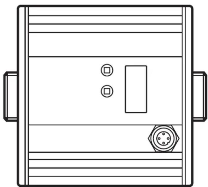
natural_image
Top-down schematic of a device casing with two connectors and a central rectangular panel (no text or symbols)Contents
1 Preliminary note....4
1.1 Symbols used ....4
1.1 Warning signs used ....4
2 Safety instructions ....4
3 Functions and features ....5
4 Function....6
4.1 Process measured signals 6
4.2 Volumetric flow monitoring....6
4.3 Consumed quantity monitoring (totaliser function) 6
4.3.1 Consumed quantity monitoring with pulse output......7
4.3.2 Consumed quantity monitoring with preset counter 7
4.4 Temperature monitoring....7
4.5 Volumetric flow or temperature monitoring / switching function......8
4.5.1 Hysteresis function 8
4.5.2 Window function 8
4.6 Volumetric flow or temperature monitoring / analogue function......9
4.6.1 Voltage output 0 ... 10 V (example volumetric flow monitoring)......9
4.6.2 Current output 4 ... 20 mA (example volumetric flow monitoring)......10
4.7 Start-up delay 10
4.8 Customer-specific calibration (CGA) 13
5 Installation....14
5.1 Recommended mounting position....14
5.2 Non recommended installation position....15
5.3 Installation in pipes 16
6 Electrical connection....16
7 Operating and display elements....18
8 Menu....19
8.1 Menu structure....19
8.2 Explanation of the menu....20
9 Set-up 21
10 Parameter setting 21
10.1 Parameter setting in general 22
10.1.1 Change from menu level 1 to menu level 2....22
10.1.2 Locking / unlocking 23
10.1.3 Timeout....23
10.2 Settings for consumed quantity monitoring 23
10.2.1 Configure limit value monitoring with OUT1 23
10.2.2 Configure limit value monitoring with OUT2 24
10.2.3 Configure analogue value for volumetric flow....24
10.3 Settings for consumed quantity monitoring 24
10.3.1 Configure quantity monitoring via pulse output 24
10.3.2 Configure quantity monitoring via the preset counter 24
10.3.3 Setting the pulse value 25
10.3.4 Manual counter reset....25
10.3.5 Time-controlled counter-reset....26
10.3.6 Deactivate meter reset 26
10.3.7 Configure meter reset using an external signal....26
10.4 Settings for temperature monitoring 26
10.4.1 Configure limit value monitoring with OUT2 26
10.4.2 Configure analogue value for temperature....26
10.5 User settings (optional)....27
10.5.1 Set standard unit of measurement for volumetric flow .....27
10.5.2 Configuration of the standard display 27
10.5.3 Setting the output logic 27
10.5.4 Calibrate curve of measured values....27
10.5.5 Reset calibration data....27
10.5.6 Setting the start-up delay....27
10.5.7 Set measured value damping....28
10.5.8 Set output status in fault condition....28
10.5.9 Select the medium to be monitored....28
10.6 Service functions 28
10.6.1 Read min/max values for volumetric flow 28
10.6.2 Reset all parameters to factory setting 28
11 Operation 29
11.1 Reading the process value 29
11.2 Change display unit in the Run mode 29
11.3 Read set parameters 30
11.4 Fault indications 30
12 Technical data....30
13 Factory setting 31
1 Preliminary note
1.1 Symbols used
▶ Instructions
Reaction, result
[...] Designation of keys, buttons or indications
→ Cross-reference

Important note
Non-compliance can result in malfunction or interference.
1.1 Warning signs used

CAUTION
Warning of personal injury.
Slight reversible injuries may result.
2 Safety instructions
- Please read this document prior to set-up of the unit. Ensure that the product is suitable for your application without any restrictions.
- If the operating instructions or the technical data are not adhered to, personal injury and/or damage to property can occur.
- Improper or non-intended use may lead to malfunctions of the unit or to unwanted effects in your application. That is why installation, electrical connection, set-up, operation and maintenance of the unit must only be carried out by qualified personnel authorised by the machine operator.
- In order to guarantee the correct condition of the device for the operating time it is necessary to use the device only for media to which the wetted materials are sufficiently resistant ( Technical data).
- The responsibility whether the measurement devices are suitable for the respective application lies with the operator. The manufacturer assumes no
liability for consequences of misuse by the operator. Improper installation and use of the devices results in a loss of the warranty claims.
- For medium temperatures above 50 °C (122 °F) some parts of the housing can heat up to over 65 °C (149 °F). Moreover, during installation or in case of a fault (e.g. housing damage) media under high pressure or hot media can leak from the system. To avoid personal injury, take the following measures:
▶ Install the unit according to the applicable rules and regulations.
▶ Ensure that the system is free of pressure during installation.
▶ Protect the housing against contact with flammable substances and unintentional contact. To do so, equip the unit with suitable protection (e.g. protective cover).
▶ Do not press the pushbuttons manually; instead use another object (e.g. ballpoint pen).
3 Functions and features
Pressure Equipment Directive (PED): The units comply with section 3, article 3 of the Directive 97/23/EC and must be designed and manufactured for non-superheated liquids of group 2 fluids in accordance with the sound engineering practice.
The unit monitors liquid media.
It detects the 3 process categories volumetric flow, consumed quantity, medium temperature.
Application area
- Water
- Glycol solutions
- Low viscosity oils (viscosity: 7...40 mm ^2 /s at 40 °C / 7...40 cSt at 104 °F)
- High viscosity oils (viscosity: 30...68 mm ^2 /s at 40 °C / 30...68 cSt at 104 °F)
Selection of the medium to be monitored → 10.5.9.
4 Function
4.1 Process measured signals
The unit displays the current process values.
It generates 2 output signals according to the parameter setting.
OUT1: 3 selection options Parameter setting
- Switching signal for volumetric flow quantity limit value ( 10.2.1)
- or pulse signal for quantity meter (→ 10.3.1)
- or switching signal for preset counter (→ 10.3.2)
OUT2: 4 selection options Parameter setting
- Switching signal for volumetric flow quantity limit value ( 10.2.2)
- or switching signal for temperature limit value (→ 10.4.1)
- or analogue signal for volumetric flow quantity ( 10.2.3)
- or analogue signal for temperature (→ 10.4.2)
- or input for external reset signal (InD) ( 10.3.7)
If not used as an output, OUT2 (pin 2) can instead be used ( 10.3.7) as an input for an external reset signal
4.2 Volumetric flow monitoring
The volumetric flow is monitored by an ultrasonic measuring system, the measured signals are evaluated by the electronics.
The signals for measuring the volumetric flow quantity can be provided as follows:
- Two switching signals for volumetric flow quantity limit values on output 1 and output 2 ( 4.5).
- An analogue signal proportional to the volumetric flow (4...20 mA or 0...10 V) on output 2 ( 4.6).
4.3 Consumed quantity monitoring (totaliser function)
The unit has an internal quantity meter which continuously totals the volumetric flow quantity. The sum corresponds to the current consumed quantity since the last reset.
- The current meter reading can be displayed.
- In addition the value before the last reset is saved. This value can also be displayed.

The meter saves the totalled consumed quantity every 10 minutes. After a power failure this value is available as the current meter reading. If a time-controlled reset is set, the elapsed time of the set reset interval is also saved. So the possible data loss can be maximum 10 minutes.
The meter can be reset as follows:
→ 10.3.4 Manual counter reset.
→ 10.3.5 Time-controlled counter-reset.
→ 10.3.7 Configure meter reset using an external signal.
4.3.1 Consumed quantity monitoring with pulse output
Output 1 indicates a counting pulse when the set volumetric flow quantity has been reached ( 10.3.1).
4.3.2 Consumed quantity monitoring with preset counter
Output 1 switches when the set volumetric flow quantity has been reached ( 10.3.2). 2 types of monitoring are possible:
- Time-dependent quantity monitoring ( 10.3.5 Time-controlled counter-reset):
- If the quantity x is reached during t, output 1 switches and remains switched until the counter is reset.
-
If the quantity x is not reached after the time t has elapsed, the meter is automatically reset and counting starts again; output 1 does not switch.
-
Non time-dependent quantity monitoring ( 10.3.6 Deactivate meter reset)
- If the quantity x is reached, output 1 switches and remains switched until the counter is reset.
4.4 Temperature monitoring
The following signals are provided for temperature monitoring:
- A switching signal for temperature limit values on output 2 ( 4.5).
- An analogue signal proportional to the temperature (4...20 mA or 0...10 V) on output 2 ( 4.6).
4.5 Volumetric flow or temperature monitoring / switching function
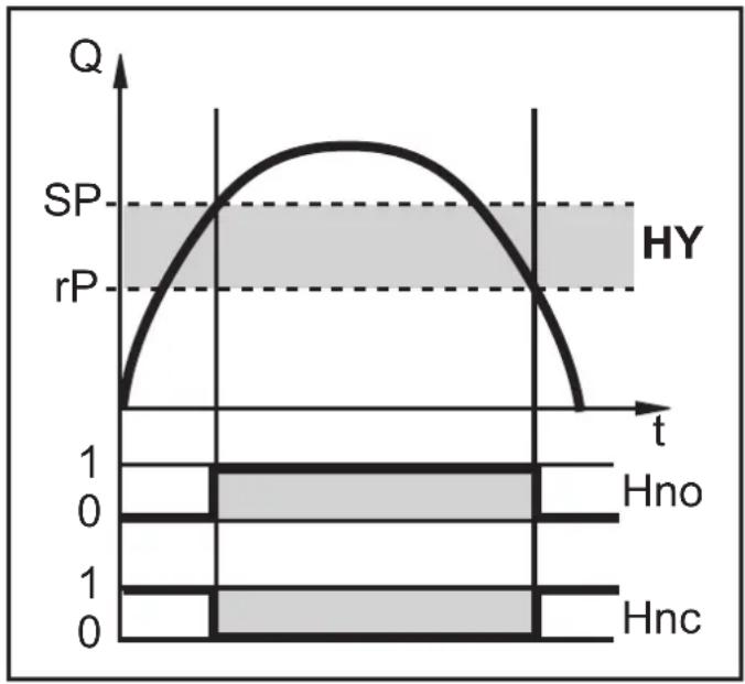
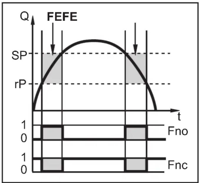
OUTx changes its switching status if it is above or below the set switching limits (SPx, rPx). The following switching functions can be selected:
4.5.1 Hysteresis function
line
| t | Q | | ---- | ----- | | 0 | 0 | | 1 | SP | | 2 | rP | | 3 | 0 | | 4 | 0 |Example of volumetric flow monitoring HY = hysteresis
Normally open: [OUx] = [Hno]
Normally closed: [OUx] = [Hnc]
First the set point (SPx) is set, then the reset point (rPx) with the requested difference.

When SPx is adjusted, rPx is changed automatically; the difference remains constant.
4.5.2 Window function
line
| t | Q | | ---- | ----- | | 0 | 0 | | 1 | SP | | 2 | rP | | 3 | SP | | 4 | rP | | 5 | SP | | 6 | rP | | 7 | SP | | 8 | rP | | 9 | SP | | 10 | rP | | 11 | SP | | 12 | rP | | 13 | SP | | 14 | rP | | 15 | SP | | 16 | rP | | 17 | SP | | 18 | rP | | 19 | SP | | 20 | rP | | 21 | SP | | 22 | rP | | 23 | SP | | 24 | rP | | 25 | SP | | 26 | rP | | 27 | SP | | 28 | rP | | 29 | SP | | 30 | rP | | 31 | SP | | 32 | rP | | 33 | SP | | 34 | rP | | 35 | SP | | 36 | rP | | 37 | SP | | 38 | rP | | 39 | SP | | 40 | rP | | 41 | SP | | 42 | rP | | 43 | SP | | 44 | rP | | 45 | SP | | 46 | rP | | 47 | SP | | 48 | rP | | 49 | SP | | 50 | rP | | 51 | SP | | 52 | rP | | 53 | SP | | 54 | rP | | 55 | SP | | 56 | rP | | 57 | SP | | 58 | rP | | 59 | SP | | 60 | rP | | 61 | SP | | 62 | rP | | 63 | SP | | 64 | rP | | 65 | SP | | 66 | rP | | 67 | SP | | 68 | rP | | 69 | SP | | 70 | rP | | 71 | SP | | 72 | rP | | 73 | SP | | 74 | rP | | 75 | SP | | 76 | rP | | 77 | SP | | 78 | rP | | 79 | SP | | 80 | rP | | 81 | SP | | 82 | rP | | 83 | SP | | 84 | rP | | 85 | SP | | 86 | rP | | 87 | SP | | 88 | rP | | 89 | SP | | 90 | rP | | 91 | SP | | 92 | rP | | 93 | SP | | 94 | rP | | 95 | SP | | 96 | rP | | 97 | SP | | 98 | rP | | 99 | SP | | 100 | rP |Example of volumetric flow monitoring
FE = window
Normally open: [OUx] = [Fno]
Normally closed: [OUx] = [Fnc]
The width of the window can be set by means of the difference between SPx and rPx.
SPx = upper value
rPx = lower value

When set to the window function the set and reset points have a fixed hysteresis of 0.25 % of the final value of the measuring range. This keeps the switching status of the output stable if the volumetric flow varies slightly.
4.6 Volumetric flow or temperature monitoring / analogue function
4.6.1 Voltage output 0 ... 10 V (example volumetric flow monitoring)
Factory setting Measuring range scaled

line
| Q | U [V] | |-------|-------| | 0 | 0 | | >2 | 10 |
line
| MEWAEPASP Q | U [V] | | ----------- | ----- | | 0 | 0 | | Peak | 10 |MEW = final value of the measuring range
ASP = analogue start point: determines at which measured value the output signal is 4 mA
AEP = analogue end point: determines at which measured value the output signal is 20 mA.

Minimum distance between ASP and AEP = 20 % of the measuring range.
In the set measuring range the output signal is between 0 and 10V.
For an output signal > 10 V the flow quantity is above the final value of the measuring range.
4.6.2 Current output 4 ... 20 mA (example volumetric flow monitoring)
Factory setting Measuring range scaled

line
| t | I [mA] | | ---- | ------ | | 0 | 4 | | 6 | 20 | | >6 | 25 |
line
| Q | I [mA] | | ------- | ------ | | 0 | 4 | | >1.5 | 20 |MEW = final value of the measuring range
ASP = analogue start point: determines at which measured value the output signal is 4 mA
AEP = analogue end point: determines at which measured value the output signal is 20 mA.

Minimum distance between ASP and AEP = 20 % of the measuring range.
In the set measuring range the output signal is between 4 and 20 mA.
For an output signal > 20 mA the flow quantity is above the final value of the measuring range.
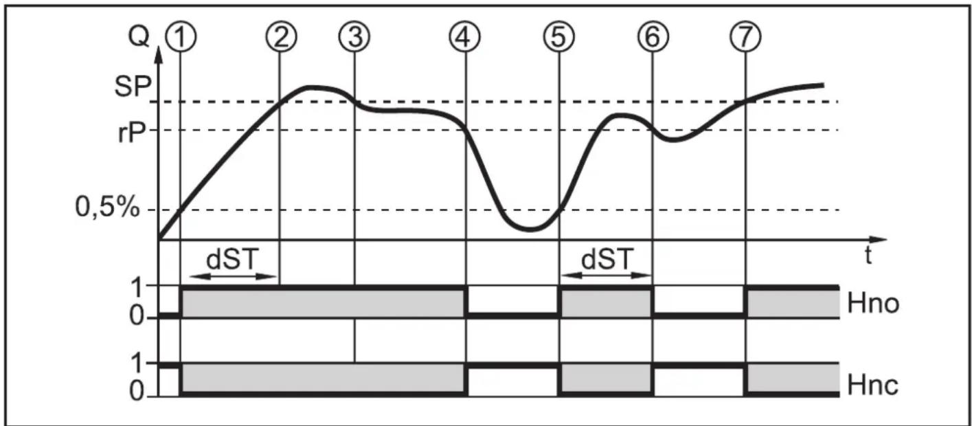
4.7 Start-up delay

The start-up delay dST influences the switching outputs of the volumetric flow monitoring.
If the start-up delay is active (dST > 0), note: as soon as the volumetric flow exceeds 0.5 % of the final value of the measuring range, the following processes are carried out:
The start-up delay is activated.
The outputs switch as programmed:
ON for NO function, OFF for NC function.
After the start of the start-up delay there are 3 options:
- The volumetric flow increases quickly and reaches the set point / good range within dST.
Outputs remain active.
- The volumetric flow increases slowly and does not reach the set point /good range within dST.
Outputs are reset.
- Volumetric flow quantity falls below 0.5 % of the final value of the measuring range within [dST].
Outputs are reset at once; dST is stopped.
Example: dST for hysteresis function
line
| t | SP | rP | |---|--------|--------| | ① | ~0.5% | ~0.5% | | ② | ~0.75% | ~0.5% | | ③ | ~0.65% | ~0.5% | | ④ | ~0.45% | ~0.5% | | ⑤ | ~0.25% | ~0.5% | | ⑥ | ~0.45% | ~0.5% | | ⑦ | ~0.65% | ~0.5% || Condition Reaction | ||
| 1 | Volumetric flow quantity Q reaches 0.5 % of VMR | dST starts, output becomes active |
| 2 dST elapsed, Q reached SP output remains active | ||
| 3 Q below SP but above rP output remains active | ||
| 4 Q below rP output is reset | ||
| 5 Q reaches again 0.5 % of VMR dST starts, output becomes active | ||
| 6 dST elapsed, Q has not reached SP output is reset | ||
| 7 Q reaches SP output becomes active | ||

Example: dST for window function

line
| t | SP | rP | |---|--------|--------| | ① | 0.5% | 0.5% | | ② | 0.5% | 0.5% | | ③ | 0.5% | 0.5% | | ④ | 0.5% | 0.5% | | ⑤ | 0.5% | 0.5% | | ⑥ | 0.5% | 0.5% | | ⑦ | 0.5% | 0.5% | | ⑧ | 0.5% | 0.5% || Condition Reaction | ||
| 1 | Volumetric flow quantity Q reaches 0.5 % of VMR | dST starts, output becomes active |
| 2 | dST elapsed, Q reached good range output remains active | |
| 3 | Q above SP (leaves good range) output is reset | |
| 4 | Q again below SP output becomes active again | |
| 5 | Q below rP (leaves good range) output is reset again | |
| 6 | Q reaches again 0.5 % of VMR dST starts, output becomes active | |
| 7 | dST elapsed, Q has not reached good range | output is reset |
| 8 | Q reaches good range output becomes active | |
4.8 Customer-specific calibration (CGA)
The customer-specific calibration allows changing the gradient of the curve of measured values ( 10.5.4). It influences the display and the outputs.

line
| Scenario | MEW (%) | MEW (%) | | :--- | :--- | :--- | | V0 | 60 | 100 | | V1 | 140 | 140 | | V2 | 60 | 100 |A = operating value for display and output signals
$$ Q = \text { flow } $$
MEW = final value of the measuring range
V0 = curve of measured values with factory setting
V1, V2 = curve of measured values after calibration
The change in the gradient is indicated in per cent. Factory setting = 100 %. After a change the calibration can be reset to factory setting ( 10.5.5).
5 Installation

▶ Avoid deposits, accumulated gas and air in the pipe system.
5.1 Recommended mounting position
▶ Install the unit in that section of the plant where the medium flows under pressure. This avoids disturbance by air bubbles.
▶ Install the unit so that the measuring pipe is completely filled.
▶ Arrange for inlet and outlet pipe lengths. Disturbances caused by bends, valves, reductions, etc. are compensated for.
It applies in particular: No shut-off and control devices are allowed directly in front of the unit.
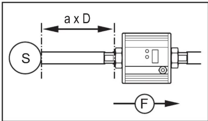
S = disturbance
D = pipe diameter
F = flow direction
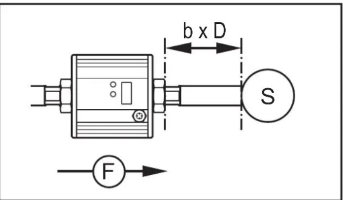
SU7001, SU8001: a = 5 b = 2
SU9001: a = 8 b = 3
▶ Install in front of or in a rising pipe.

natural_image
Pure electrical circuit lines without any symbols
natural_image
Technical diagram of a pressure regulator with pipe connection and force indicator (no text labels)5.2 Non recommended installation position
▶ Avoid the following installation positions:
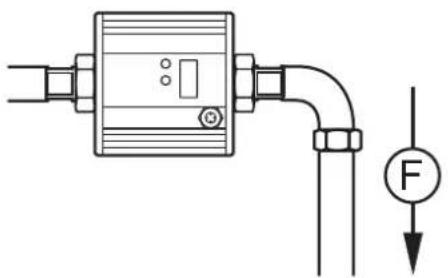
natural_image
Pure electrical circuit lines without any symbolsDirectly in front of a falling pipe. In a

natural_image
Pure electrical circuit lines without any symbolsfalling pipe.
UK

At the highest point of the pipe system.

Directly in front of the spout of the pipe.

natural_image
Pure electrical circuit lines without any symbolsOn the suction side of a pump.

natural_image
Technical line drawing of a mechanical device with mounting flanges and a force gauge symbol (no text or labels)Flow rate direction horizontal, unit vertical, connector upwards.
F = flow direction
5.3 Installation in pipes
The unit can be installed in pipes using adapters.

Information about the available adapters at www.ifm.com.

- Screw the adapter (B) into the pipe (A).
- Place the seals (C) and install the unit according to the marked flow direction.

▶ To mount the adapters on the process connection of the sensor use suitable lubricants.
-
Screw the adapter (B) with the threads (D) until it is hand-tight.
-
Tighten the two adapters in opposite direction (tightening torque: 30 Nm).
After installation air bubbles in the system can affect the measurement.
Corrective measures:
▶ Rinse the system after installation for ventilation.
- Rinsing quantity for SU7001 / SU8001: > 1 gpm; > 4 l/min
- Rinsing quantity for SU9001: > 5 gpm; > 20 l/min
6 Electrical connection

The unit must be connected by a qualified electrician.
The national and international regulations for the installation of electrical equipment must be adhered to.
Voltage supply according to EN 50178, SELV, PELV.
▶ Disconnect power.
▶ Connect the unit as follows:
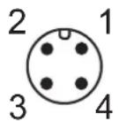
BK: black
BN: brown
BU: blue
WH: white
Colours to DIN EN 60947-5-2

flowchart
graph TD
    A[" "] -->|1| B["BN"]
    A -->|2| C["WH"]
    A -->|4| D["BK"]
    A -->|3| E["BU"]
    B --> F["L+"]
    C --> G["OUT2"]
    D --> H["OUT1"]
    E --> I["L-"]
Sample circuits:
2 x positive switching 2 x negative switching

flowchart
graph TD
    A["Component"] --> B["1 BN"]
    A --> C["2 WH"]
    A --> D["4 BK"]
    A --> E["3 BU"]
    B --> F["L+"]
    C --> G["Block"]
    D --> H["Block"]
    E --> I["L-"]

flowchart
graph TD
    A["Component"] --> B["1 BN"]
    A --> C["2 WH"]
    A --> D["3 BU"]
    A --> E["4 BK"]
    A --> F["L+"]
    A --> G["L-"]
1 x positive switching / 1 x analogue 1 x negative switching / 1 x analogue
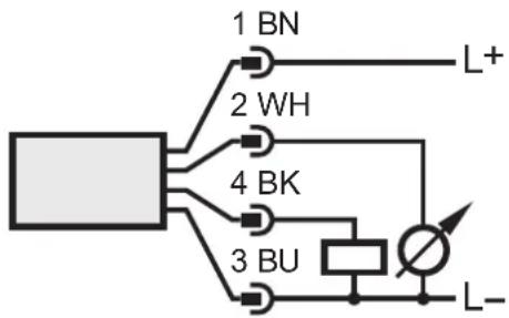
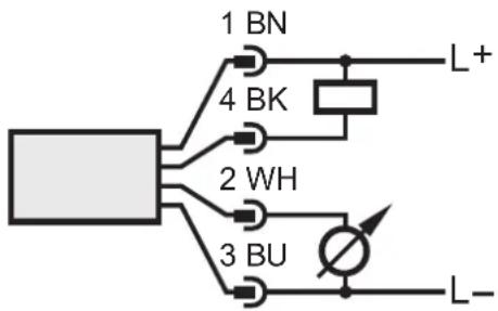
| Pin 1 L+ | |
| Pin 3 L- | |
| Pin 4(OUT1) | Switching signal: limit values for volumetric flowSwitching signal: quantity meter reached preset valuePulse signal: 1 pulse every time the defined volumetric flow quantity is reached |
| Pin 2(OUT2/InD) | Switching signal: limit values for volumetric flowSwitching signal: limit values for temperatureAnalogue signal for volumetric flowAnalogue signal for temperatureInput for external reset signal (InD) |
7 Operating and display elements
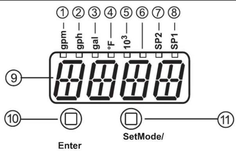
| 1 to 8: Indicator LEDs |
| • LEDs 1-5 = unit of the currently represented numerical value → 11.1 Reading the process value• LED 6 = not used• LED 7 = switching status of output OUT2 / of input InD• LED 8 = switching status of output OUT1 |
| 9: Alphanumeric display, 4 digits |
| • Current volumetric flow quantity (with setting [SELd] = FLOW)• Meter reading of the totaliser (with setting SELd = TOTL)• Current medium temperature (with setting SELd = TEMP)• Parameters and parameter values |
| 10: [Mode/Enter] button |
| • Selecting the parameters• Reading the set values• Confirming the parameter values |
| 11: [Set] button |
| • Selection of the parameters• Activation of the setting functions• Changing the parameter values• Change of the display unit in the normal operating mode (Run mode) |
8 Menu
8.1 Menu structure

flowchart
graph TD
    A["gpm"] --> B["SP1"]
    B --> C["m 200"]
    C --> D["rP1"]
    D --> E["m 100"]
    E --> F["ImPS"]
    F --> G["m 02"]
    G --> H["m ImPP"]
    H --> I["m YES no"]
    I --> J["OU1"]
    J --> K["m 1000"]
    K --> L["OU2"]
    L --> M["m 800"]
    M --> N["SP2"]
    N --> O["m 1000"]
    O --> P["rP2"]
    P --> Q["m 800"]
    Q --> R["ASP"]
    R --> S["m 000"]
    S --> T["REP"]
    T --> U["m 1200"]
    U --> V["DIin2"]
    V --> W["m + EDG"]
    W --> X["EF"]
    X --> Y["m Mode/Enter"]
    X --> Z["s Set"]

    subgraph Module_Output
        AA["HI"] --> AB["m 1320"]
        AC["LO"] --> AD["m 000"]
        AE["CGA"] --> AF["m 100"]
        AG["CAr"] --> AH["m ----"]
        AI["FOU1"] --> AJ["m OFF"]
        AK["FOU2"] --> AL["m OFF"]
        AM["dSt"] --> AN["m 00"]
        AO["P-n"] --> AP["m PnP"]
        AQ["dAP"] --> AR["m 06"]
        AS["rTo"] --> AT["m OFF"]
        AU["d,S"] --> AV["m d2"]
        AW["Un"] --> AX["m GPm"]
        AY["SELd"] --> AZ["m FLOW"]
        BA["SEL2"] --> BB["m FLOW"]
        BC["MEDI"] --> BD["m H2O"]
        BE["rES"] --> BF["m ----"]
    end

    style Module_Output fill:#f9f,stroke:#333
gal = current meter count in gal
gal* = stored meter count in gal
8.2 Explanation of the menu
| SP1 / rP1 Upper / lower limit value for volumetric flow | |
| ImPS Pulse value | |
| ImPR | Pulse repetition active (= pulse output function) or not active(= preset counter function) |
| OU1 | Output function for OUT1 (volumetric flow or consumed quantity):- Switching signal for the limit values: hysteresis function or window func-tion, either normally open or normally closed- Pulse or switching signal for quantity meter |
| OU2 | Output function for OUT2 (volumetric flow or temperature):- Switching signal for the limit values: hysteresis function or window func-tion, either normally open or normally closed- Analogue signal: 4...20 mA [I] or 0...10 V [U] |
| As an alternative: configure OUT2 (pin 2) as input for external reset signal:Setting: [OU2] = [InD] | |
| SP2 / rP2 Upper / lower limit value for volumetric flow or temperature | |
| ASP Analogue start value for volumetric flow or temperature | |
| AEP Analogue end value for volumetric flow or temperature | |
| DIn2 Configuration of the input (pin 2) for counter reset | |
| EF Extended functions / opening of menu level 2 | |
| HI / LO Maximum / minimum value memory for volumetric flow | |
| CGA Customer-specific calibration of the curve of measured values | |
| CAr Reset calibration data | |
| FOU1 Status of output 1 in case of a device fault | |
| FOU2 Status of output 2 in case of a device fault | |
| dST Start-up delay | |
| P-n Output logic: pnp / npn | |
| dAP Measured value damping / damping constant in seconds | |
| rTo Meter reset: manual reset / time-controlled reset | |
| diS Update rate and orientation of the display | |
| Uni Standard unit of measurement for volumetric flow: gal/minute or gal/hour | |
| SELd Standard measured variable of the display: volumetric flow value / meter reading / medium temperature | |
| SEL2 Standard measured variable for evaluation by OUT2:- limit value signal or analogue signal for volumetric flow- limit value signal or analogue signal for temperature | |
| MEDI Selection of the medium to be monitored | |
| rES Restore the factory setting | |
9 Set-up
After power on and expiry of the power-on delay time of approx. 10 s the unit is in the Run mode (= normal operating mode). It carries out its measurement and evaluation functions and generates output signals according to the set parameters.
- During the power-on delay time the outputs are switched as programmed:
- ON with normally open function (Hno / Fno)
- OFF with normally closed function (Hnc / Fnc).
- If output 2 is configured as analogue output, the output signal is at 20 mA (current output) or 10 V (voltage output).
10 Parameter setting
Parameters can be set before installation and set-up of the unit or during operation.

If you change parameters during operation, this will influence the function of the plant.
▶ Ensure that there will be no malfunctions in your plant.
During parameter setting the unit remains in the operating mode (Run mode). It continues to monitor with the existing parameter until the parameter setting has been completed.

CAUTION
For medium temperatures above 50 °C ( 122 °F ) some parts of the housing can heat up to over 65 °C ( 149 °F ).
▶ Do not press the pushbuttons manually; instead use another object (e.g. ballpoint pen).
10.1 Parameter setting in general
3 steps must be taken for each parameter setting:
| 1 | Select parameter► Press [Mode/Enter] until the requested parameter is displayed. |   | 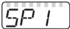 |
| 2 | Set parameter value► Press and hold [Set].> Current setting value of the parameter flashes for 5 s.> After 5 s: setting value is changed: incrementally by pressing the button once or continuously by keeping the button pressed. | 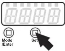 [KKY3] [KKY3] | 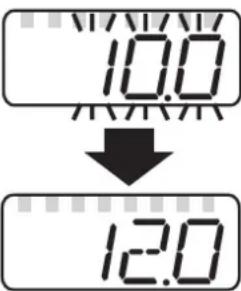 |
Numerical values are incremented continuously. For reducing the value: ► Let the display move to the maximum setting value.> Then the cycle starts again at the minimum setting value. ► Let the display move to the maximum setting value.> Then the cycle starts again at the minimum setting value. | |||
| 3 | Acknowledge parameter value► Briefly press [Mode/Enter].> The parameter is displayed again.The new setting value is saved. | 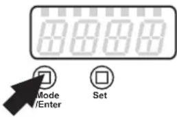  | 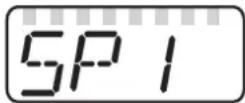 |
| Set other parameters► Start again with step 1. | |||
| Finish parameter setting and change to the process value display:► wait fors15or► press [Mode/Enter] several times until the current measured value is displayed.> The unit returns to the operating mode. | |||
10.1.1 Change from menu level 1 to menu level 2
| ▶ Press [Mode/Enter] until [EF] is displayed. |  |  | 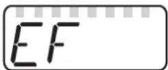 |
| ▶ Briefly press [Set].> The first parameter of the submenu is displayed (here: [HI]). |  |  | 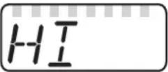 |
10.1.2 Locking / unlocking
The unit can be locked electronically to prevent unintentional settings.
| Locking:► Make sure that the unit is in the norma operating mode.► Press [Mode/Enter] + [Set] for 10 s.> [Loc] is displayed. |   |
 During operation: [LOC] is briefly displayed if you try to change parameter values. During operation: [LOC] is briefly displayed if you try to change parameter values. | |
| Unlocking:► Press [Mode/Enter] + [Set] for 10 s.> [uLoc] is displayed. | 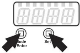  |
On delivery: not locked.
10.1.3 Timeout
If no button is pressed for 15 s during parameter setting, the unit returns to the operating mode with unchanged parameter.
10.2 Settings for consumed quantity monitoring
10.2.1 Configure limit value monitoring with OUT1
| ▶ Select [OU1] and set the switching function:- [Hno] = hysteresis function/normally open,- [Hnc] = hysteresis function/normally closed,- [Fno] = window function/normally open,- [Fnc] = window function/normally closed.▶ Select [SP1] and set the value at which the output is set.▶ Select [rP1] and set the value at which the output is reset. | 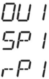 |
10.2.2 Configure limit value monitoring with OUT2
| ▶ Select [SEL2] and set [FLOW].▶ Select [OU2] and set the switching function:- [Hno] = hysteresis function/normally open,- [Hnc] = hysteresis function/normally closed,- [Fno] = window function/normally open,- [Fnc] = window function/normally closed.▶ Select [SP2] and set the value at which the output switches.▶ Select [rP2] and set the value at which the output resets. | SEL2OU2SP2rP2 |
10.2.3 Configure analogue value for volumetric flow
| ▶ Select [SEL2] and set [FLOW].▶ Select [OU2] and set the function:- [I] = current signal proportional to volumetric flow (4...20 mA);- [U] = voltage signal proportional to volumetric flow (0...10 V).▶ Select [ASP] and set the value at which the minimum value is provided.▶ Select [AEP] and set the value at which the maximum value is provided. | SEL2OU2ASPAEP |
10.3 Settings for consumed quantity monitoring
10.3.1 Configure quantity monitoring via pulse output
| ▶ Select [OU1] and set [ImP].▶ Select [ImPS] and set the volumetric flow quantity at which 1 pulse is provided (→ 10.3.3 Setting the pulse value).▶ Select [ImPR] and set [YES].> Pulse repetition is active. Output 1 provides a counting pulse each time the value set in [ImPS] is reached. | OU1ImPSImPR |
10.3.2 Configure quantity monitoring via the preset counter
| ▶ Select [OU1] and set [lmP].▶ Select [lmPS] and set the volumetric flow quantity at which output 1 switches (→ 10.3.3).▶ Select [lmPR] and set [no].> Pulse repetition is not active. The output switches ON if the value set in [lmPS] is reached. It remains switched until the counter is reset. | OU1ImPSImPR |
10.3.3 Setting the pulse value
▶ Select [lmPS].
▶ Press and hold [Set].
The current numerical value flashes for 5 s, then one of the 4 digits becomes active and can be changed as below:
- Briefly press [Set]
Active figure is changed.
- Keep [Set] pressed
The next figure on the left becomes active.

- After the cycle of the figures on the left on the display the display changes to the next higher setting range (decimal point shifts or LED changes).
-
Change to the lower setting range: Keep [Set] pressed until the display moves through all ranges and jumps back to the start value.
-
Wait without pressing a button
The next figure on the right becomes active.
▶ Briefly press [Mode/Enter] when all 4 digits are set.
Setting ranges:
| LED1) | Unit Display Value | Step in-crement | |
| 32) | gal 0.02 | gal | |
| 32) | gal | 100.0...999.9 | 100...999.9 gal |
| 33) | gal | 000.2...999.8 | 0.2...999.8 gal |
| 33) | gal | 1000...9999 | 1 000...9 999 gal |
| 3 + 5 | gal x 103 | 10.00...99.99 | 10 000...99 990 gal |
| 3 + 5 | gal x 103 | 100.0...999.9 | 100 000...999 990 gal |
| 3 + 5 | gal x 103 | 1000...9000 | 1 000 000...9 000 000 gal |
^1) indicator LED 7 Operating and display elements
2) SU7001, S8001
^3) SU9001
10.3.4 Manual counter reset
▶ Select [rTo].
▶ Press [Set] until [rES.T] is displayed.
▶ Briefly press [Mode/Enter].
The counter is reset to zero.
ImPS
rTo
10.3.5 Time-controlled counter-reset
| ▶ Select [rTo].▶ Press [Set] until the requested value is displayed (intervals from 1 hour to 8 weeks).▶ Briefly press [Mode/Enter].> The counter is reset automatically with the value now set. | r- To |
10.3.6 Deactivate meter reset
| ▶ Select [rTo] and set [OFF].> The meter is only reset after overflow (= factory setting). | r- To |
10.3.7 Configure meter reset using an external signal
| ▶ Select [OU2] and set [InD].▶ Select [Din2] and set the reset signal:- [HI] = reset for high signal,- [LOW] = reset for low signal,- [+EDG] = reset for rising edge,- [-EDG] = reset for falling edge. | OU2DIn2 |
10.4 Settings for temperature monitoring
10.4.1 Configure limit value monitoring with OUT2
| Select [SEL2] and set [TEMP].Select [OU2] and set the switching function:- [Hno] = hysteresis function/normally open,- [Hnc] = hysteresis function/normally closed,- [Fno] = window function/normally open,- [Fnc] = window function/normally closed.Select [SP2] and set the value at which the output switches.Select [rP2] and set the value at which the output resets. | SEL2OU2SP2rP2 |
10.4.2 Configure analogue value for temperature
| ▶ Select [SEL2] and set [TEMP].▶ Select [OU2] and set the function:- [I] = temperature-proportional current signal (4...20 mA);- [U] = temperature-proportional voltage signal (0...10 V).▶ Select [ASP] and set the value at which the minimum value is provided.▶ Select [AEP] and set the value at which the maximum value is provided. | SEL2OU2ASPAEP |
10.5 User settings (optional)
10.5.1 Set standard unit of measurement for volumetric flow
| ▶ Select [Uni] and set the unit of measurement: [GPm] or [GPh].The setting only has an effect on the volumetric flow value. The counter values (consumed quantity) are automatically displayed in the unit of measurement providing the highest accuracy. | Uni |
10.5.2 Configuration of the standard display
| ▶ Select [SELd] and determine the standard measuring unit:- [FLOW] = the current volumetric flow value in the standard unit of measurement is displayed.- [TOTL] = display indicates the current meter count in gal or 1000 gal.- [TEMP] = the current medium temperature in °F is displayed.▶ Select [diS] and set the update rate and orientation of the display:- [d1] = update of the measured values every 500 ms.- [d2] = update of the measured values every 1000 ms.- [d3] = update of the measured values every 2000 ms.- [rd1], [rd2], [rd3] = display as for d1, d2, d3; rotated by 180°.- [OFF] = the display is switched off in the operating mode. | SELD, S |
10.5.3 Setting the output logic
| ▶ Select [P-n] and set [PnP] or [nPn]. | P--n |
10.5.4 Calibrate curve of measured values
| ▶ Select [CGA] and set a percentage between 60 and 140 (100 = factory calibration). | CGA |
10.5.5 Reset calibration data
| ▶ Select [CAr].▶ Press and hold [Set] until [----] is displayed.▶ Briefly press [Mode/Enter].> The values are reset to the factory setting (CGA = 100). | CAr- |
10.5.6 Setting the start-up delay
| ▶ Select [dST] and set the numerical value in seconds. | dST |
10.5.7 Set measured value damping
▶ Select [dAP] and set the damping constant in seconds ( value 63 %).
dAP
10.5.8 Set output status in fault condition
▶ Select [FOU1] and set the value:
- [On] = output 1 switches ON in case of an error.
- [OFF] = output 1 switches OFF in case of a fault.
▶ Select [FOU2] and set the value:
- [On] = output 2 switches ON in case of a fault, the analogue signal goes to the upper final value.
- [OFF] = output 2 switches OFF in case of a fault, the analogue signal goes to the lower final value.
FOU I
FOU2
10.5.9 Select the medium to be monitored
▶ Select [MEDI] and set the requested medium:
- [H2O] = water
- [GLYC] = glycol solutions
- [OIL.1] = High viscosity oil(30...68 mm²/s at 40°C; 30...68 cSt at 104°F)
- [OIL.2] = Low viscosity oil (7...40 mm²/s at 40°C; 7...40 cSt at 104°F)
MEDI
10.6 Service functions
10.6.1 Read min/max values for volumetric flow
▶ Select [HI] or [Lo], briefly press [Set]. [HI] = maximum value, [Lo] = minimum value.
Delete memory:
▶ Select [HI] or [LO].
▶ Press and hold [Set] until [----] is displayed.
▶ Briefly press [Mode/Enter].
It makes sense to delete the memories as soon as the unit operates under normal operating conditions for the first time.
HI
LO
10.6.2 Reset all parameters to factory setting
▶ Select [rES].
▶ Press and hold [Set] until [----] is displayed.
▶ Briefly press [Mode/Enter].
For the factory settings please refer to the end of these instructions 13. We recommend taking down your own settings in that table before carrying out a reset.
r-ES
11 Operation
11.1 Reading the process value
The LEDs 1-5 signal which process value is currently displayed.
The process value to be displayed as standard (temperature, flow velocity or meter reading of the totaliser) can be preset ( 10.5.2 Configuration of the standard display).
A standard unit of measurement can be defined for the flow velocity (gpm or gph 10.5.1).
11.2 Change display unit in the Run mode
▶ Briefly press [Set] in the Run mode. Press the button to move to the next display unit.
The unit displays the current process value in the selected display unit for approx. 15 s, the corresponding LED is lit.

| LED Process value display Unit | |||
| 1 Current flow volume per minute gpm | |||
| 2 Current flow volume per hour gph | |||
| 3 □ | * Totaliser | Current consumed quantity since the last reset gal | |
| 3 Consumed quantity before the last reset gal | |||
| 3 + 5 □ | Current consumed quantity since the last reset | gal x 10^3 | |
| 3 + 5 □( | Consumed quantity before the last reset | gal x 10^3 | |
| 4 Current medium temperature °F | |||
□ LED is lit; 🌐 LED flashes
* The consumed quantity is automatically displayed in the unit of measurement providing the highest accuracy.
11.3 Read set parameters
▶ Briefly press [Mode/Enter] to scroll the parameters.
▶ Briefly press [Set] when the requested parameter is displayed.
The unit displays the corresponding parameter value. After about 15 s it again displays the parameter, then it returns to the Run mode.
11.4 Fault indications
| [SC1] Short circuit in OUT1. | |
| [SC2] Short circuit in OUT2. | |
| [SC] Short circuit in both outputs. | |
| [OL] Detection zone of volumetric flow or temperature exceeded.Measured value between 120 % and 130 % of the final value of the measuring range. | |
| [UL] Below the temperature detection zone: measured value below -10 °C (14 °F). | |
| [Err] • Unit faulty / malfunction.• Measured value greater than 130 % of the final value of the measuring range. | |
| [SEnS] Sensor indicates incorrect measurement. Possible cause: accumulated gas and air in the medium or unit.For more detailed diagnosis / fault assessment:► Briefly press [Set].> The latest measured values are displayed. | |
| [IOE] | Flow sensor faulty |
| [Loc] | Setting pushbuttons locked, parameter change rejected. |
12 Technical data
Technical data and scale drawing at www.ifm.com.
More information at www.ifm.com
13 Factory setting
| Factory setting | User setting | |||
| SU7001 SU | 8001 SU9001 | |||
| SP1 | 2.0 4.0 8.0 | |||
| rP1 | 1.0 2.0 4.0 | |||
| ImPS | 0.02 0.02 | 0.02 | ||
| ImPR | YES YES | YES | ||
| OU1 | Hno Hno | Hno | ||
| OU2 | III | |||
| SP2 (FLOW) | 10.0 20.0 | 2 40.0 | ||
| rP2 (FLOW) | 8.0 16.0 | 2 32.0 | ||
| SP2 (TEMP) | 136.5 136.5 | 5 136.5 | ||
| rP2 (TEMP) | 112.0 112.0 | 112.0 | ||
| ASP (FLOW) | 0.0 0.0 0.0 | |||
| AEP (FLOW) | 12.0 24.0 | 2 52.84 | ||
| ASP (TEMP) | 14.0 14.0 | 14.0 | ||
| AEP (TEMP) | 161.0 161.0 | 176.0 | ||
| DIn2 | +EDG +EDG +EDG | |||
| CGA | 100 100 | 100 | ||
| FOU1 | OFF OFF | OFF | ||
| FOU2 | OFF OFF | OFF | ||
| dST | 0.0 0.0 0 | |||
| P-n | PnP PnP | PnP | ||
| dAP | 0.6 0.6 0.6 | |||
| rTo | OFF OFF | OFF | ||
| diS | d2 | d2 | d2 | |
| Uni | GPm | GPm | GPm | |
| SELd | FLOW | FLOW | FLOW | |
| SEL2 | FLOW | FLOW | FLOW | |
| MEDI | H2O | H2O | H2O | |
UK
- Contents
- Settings for consumed quantity monitoring 23
- Settings for consumed quantity monitoring 24
- Settings for temperature monitoring 26
- User settings (optional)....27
- Service functions 28
- Operation 29
- Preliminary note
- Symbols used
- Warning signs used
- CAUTION
- Safety instructions
- Functions and features
- Application area
- Function
- Process measured signals
- Volumetric flow monitoring
- Consumed quantity monitoring (totaliser function)
- Consumed quantity monitoring with pulse output
- Consumed quantity monitoring with preset counter
- Temperature monitoring
- Volumetric flow or temperature monitoring / switching function
- Hysteresis function
- Window function
- Volumetric flow or temperature monitoring / analogue function
- Voltage output 0 ... 10 V (example volumetric flow monitoring)
- Current output 4 ... 20 mA (example volumetric flow monitoring)
- Start-up delay
- Customer-specific calibration (CGA)
- Installation
- Recommended mounting position
- Non recommended installation position
- Installation in pipes
- Electrical connection
- Sample circuits:
- Operating and display elements
- Menu
- Menu structure
- Set-up
- Parameter setting
- Parameter setting in general
- Change from menu level 1 to menu level 2
- Locking / unlocking
- Timeout
- Settings for consumed quantity monitoring
- Configure limit value monitoring with OUT1
- Configure limit value monitoring with OUT2
- Configure analogue value for volumetric flow
- Settings for consumed quantity monitoring
- Configure quantity monitoring via pulse output
- Configure quantity monitoring via the preset counter
- Setting the pulse value
- Manual counter reset
- Time-controlled counter-reset
- Deactivate meter reset
- Configure meter reset using an external signal
- Settings for temperature monitoring
- Configure limit value monitoring with OUT2
- Configure analogue value for temperature
- User settings (optional)
- Set standard unit of measurement for volumetric flow
- Configuration of the standard display
- Setting the output logic
- Calibrate curve of measured values
- Reset calibration data
- Setting the start-up delay
- Set measured value damping
- Set output status in fault condition
- Select the medium to be monitored
- Service functions
- Read min/max values for volumetric flow
- Reset all parameters to factory setting
- Operation
- Reading the process value
- Change display unit in the Run mode
- □ LED is lit; 🌐 LED flashes
- Read set parameters
- Fault indications
- Technical data
Brand : IFM
Model : SU9001
Category : Capteur de débit ultrasonique