
SF-6200MA - Receiver Epcom - Free user manual and instructions
Find the device manual for free SF-6200MA Epcom in PDF.


| Brand | Epcom |
| Model | SF-6200MA |
| Product Type | Receiver |
| Dimensions (W x D x H) | 300 x 200 x 50 mm |
| Weight | 1.5 kg |
| Power Supply | AC 100-240V, 50/60Hz |
| Power Consumption | 15 W (max) |
| Standby Power Consumption | <1 W |
| Signal Type | Digital terrestrial (DVB-T/T2) |
| Supported Video Resolutions | 720p, 1080i, 1080p |
| Supported Audio Formats | MPEG-1/2/4, AAC, HE-AAC |
| Output Ports | HDMI, Composite, Coaxial, Optical |
| Input Ports | Antenna RF, USB 2.0 |
| USB Playback | Yes, supports FAT32/NTFS |
| Channel Memory | Up to 1000 channels |
| Electronic Program Guide (EPG) | Yes, 7-day |
| Parental Control | Yes (PIN lock) |
| Safety Features | CE, RoHS compliant |
| Maintenance | Wipe with dry cloth, avoid liquids |
| Repairability | Spare parts available from manufacturer |
Frequently Asked Questions - SF-6200MA Epcom
User questions about SF-6200MA Epcom
0 question about this device. Answer the ones you know or ask your own.
Ask a new question about this device
Download the instructions for your Receiver in PDF format for free! Find your manual SF-6200MA - Epcom and take your electronic device back in hand. On this page are published all the documents necessary for the use of your device. SF-6200MA by Epcom.
USER MANUAL SF-6200MA Epcom
VOICE EVACUATION & PUBLIC ADDRESS SYSTEM
SF6200MA
SF6200MS
Thanks for using EPCOM Voice Evacuation& Public Adjusted. For better operation, please read this manual carefully before operating the
Contents
Contents....2
1 Product renderings....3
1.1 SF6200MA Product design skét2U) 3
1.2 SF6200MS Product design sketch (2U) 3
2 Main function introduction....4
2.1 SF6200MA Function feature....4
2.2 SF6200MS Features....5
3 Main technical parameters Specifications....6
3.1 Electrical Specifications....6
3.2 Performance Specifications....6
4 Device function description....11
4.1 Front panel function description.... 11
4.2 Rear panel function description....12
5 Operation Instructions....14
5.1 Self-test function.... 14
5.2 Emergency function.... 14
5.3 Local sound source play....15
5.4 PTT paging....16
5.5 Line detection....16
5.6 Volume control....17
5.7 IP address Reset....18
5.8 Power-down switching function....18
5.9 Voice Evacuation Router address Settings....19
1 Product renderings
1.1 SF6200MA Product design sketch (2U)

FIGURE 1-1 SF6200MAProduct renderings
1.2 SF6200MS Product design sketch (2U)

FIGURE 1-2 SF6200MS Product renderings
2 Main function introduction
2.1 SF6200MA Function feature
■ Built-in 500W amplifier, integrated 8 power A + B independent dual speaker loop partition output, each partition has a LED indicator, independent volume adjustment (6 files), forcibly cut to output power 100V when receive alarm signal.
■ Partition output with three-wire, four-wire Strong cut regulation function.
■ With amplifier monitoring function.
■ With 4 audio input, 2 microphone input with 24V phantom power
■ Integrated independent EVAC voice information player. Voice files can be customized by users
■ Built-in HD audio module, support to record real-time PPT voice during fire alarm.
■ Support TCP / IP communication protocol, after connecting to internet, all equipment in the system can be operated in real time through PC client-side, and the state automatically synchronized.
■ Extensible to more 19 Extension Controller and 32 remote microphones (allow to change priority level)
■ 2 channel of remote MIC online interface with 24 V power, using standard RJ-45 network port and CAT-5 network cable, achieving lone-distance transmission.
■ Function of fault self-checking of the electrical system, and complete inspection of manual system.
■ Measuring function of the status of each partition speaker loop(open circuit, short circuit, overcurrent, impedance change).
■ With system failure, emergency dry node output, emergency reset dry node input.
■ The real-time indication function of the system status.
■ 8- ways short circuit/level trigger manner, 3-way different audio sources to configure the trigger response, output can be configured with arbitrary, partition and Short circuit contact combination.
- External connecting a backup power amplifier, when the built-in amplifier doesn't work, it will switch to the backup amplifier automatically.
■ External 24V stand-by power supply, realizing continuous work without delay when power off.
■ Built-in 24V automatic charging function
■ With one way IP address reset port.
2.2 SF6200MS Features
■ Built-in 500W amplifier, integrated 8 power A + B independent dual speaker loop partition output, each partition has a LED indicator, independent volume adjustment (6 files), forcibly cut to output power 100V when receive alarm signal.
■ Partition output with three-wire, four-wire Strong cut regulation function.
■ With 4 audio input, 2 microphone input with 24V phantom power.
■ Function of fault self-checking of the electrical system, and complete inspection of manual system.
■ Measuring function of the status of each partition speaker loop(open circuit, short circuit, overcurrent, impedance change).
■ The real-time indication function of the system status.
■ 8- ways short circuit/level trigger manner, 3-way different audio sources to configure the trigger response, output can be configured with arbitrary, partition and Short circuit contact combination.
- External connecting a backup power amplifier, when the built-in amplifier doesn't work, it will switch to the backup amplifier automatically.
■ External 24V stand-by power supply, realizing continuous work without delay when power off.
■ Built-in 24V automatic charging function
■ With one way IP address reset port.
■ 6-bit address DIP switch, can set the extended address.
3 Main technical parameters Specifications
3.1 Electrical Specifications
① Power supply
● Voltage \~ 110V ± 20%, 60Hz
- Fuse Size 4.5A
3.2 Performance Specifications
① Analog audio
✨ microphone input
● Sensitivity ± 2.5mV
● Frequency response 200Hz \~ 10kHz
- Input impedance 1kΩ
● Signal to noise ratio> 70dB
✿ Unbalanced auditinput
● Sensitivity of 350mV
● Frequency response 80Hz \~ 16kHz
- Impedance 10kΩ
● Signal to noise ratio> 70dB
✨ Balanced line input
● Sensitivity ± 350mV
● Frequency response 80Hz \~ 16kHz
- Input impedance 20kΩ
● Signal to noise ratio> 70dB
✨ Balance line output
● Amplitude ± 500mV
● Distortion <0.1%, 1kHz
● Frequency response 80Hz \~ 16kHz
● Output impedance 470Ω
● Signal to noise ratio> 70dB
② Communication
✨ RS485 interface
● Backup equipment RS485 interface
● Support maximum baud rate of 38400bps
● Supports up to 16 Backup equipments
✨ CAN interface
- Remote MIC console CAN interface
● Baud rate of 38400bps
● Supports up to 20 remote MIC consoles
③ Trigger input
Short circuit mode: short circuit
④ Mechanical indicators
- Size (L × W × H) : 484*350*88 mm (19 "wide, 2U)
● Net weight : 11.4 Kg
● Install : tabletop or 19-inch cabinet - Color: black
⑤ Environmental requirements
- Operating temperature +5 °C \~ +40 °C
● Storage temperature -20 °C \~ +70 °C
● Relative temperature <95%
4 Device function description
The bellowed is front panel introduction for controller SF6200MA ( for SF6200MS detailed function, please refer to SF6200MAas they are with same front panel printing ):
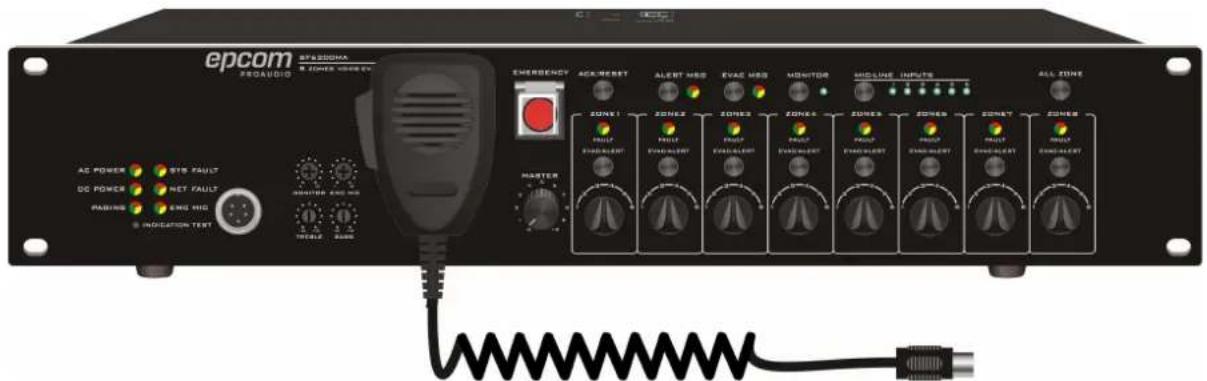
Figure 4-1 SF6200MAfront panel design sketch
4.1 Front panel function description
■ Indicator and status description:
AC POWER: 110V AC indicator, green on means normal, orange on means AC power off.
DC POWER: DC power indicator light, green on means 24V power connected, orange on means out of connect to DC 24V, light off means without configuration for DC power.
➢ PAGING: remote control microphone indicator, green light means that the remote control microphone is paging the zone from the host.
➢ SYS FAULT: orange indicates the host is faulty, flashing indicates that the host has a new fault.
NET FAULT: green means the network is normal, orange means the network is with failure.
➢ EMC MIC:light off if well connected, green means PPT is paging, orange means PPT is with failure.
■ Volume potentiometer:
➢ MONOROR: Monitor volume adjustment.
➢ EMC MIC: PPT microphone volume adjustment.
REBLE: Treble adjustment.
➢ BASS:: Bass adjustment.
■ ENERGENCY: emergency broadcast button, press to select ALERT MSG or EVAC MSG to broadcast emergency voice message, EVAC MSG is prior to ALERT
MSG, then press ENERGENCY button, to close the broadcast.
■ ACK/RESET: machine fault alarm reset button.
■ ALERT MSG: Play emergency evacuation voice.
■ EVAC MSG: Play fire alarm alert voice.
■ MONITOR :buttons to switch on and off monitor.
■ MIC / LINE INPUTS: button to select or switch the source.
■ ALL ZONE: button to select open or close all zone.
■ ZONE1\~ZONE8:
➢ Indicator: Indicates current zone status
-
Orange: fault
-
Green: normal
➢ Zone switch button: switch on or off the zone.
➢ Volume adjustment button: 6 grades volume adjustment knob.
4.2 Rear panel function description
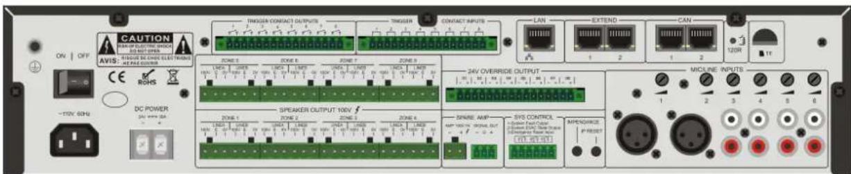
Figure 4-2 SF6200MArear panel design sketch
■ ON for power on, OFF for power off.
■ DC POWER: 24V DC input interface, pay attention to positive and negative, Do not reverse!
■ 100V output interface, 24V relay control interface.
■ SPERKER OUTPUT 100V.
ZONE1 \~ 8
LINE A:zone A.
LINE B:zone B.
➢ 100V: loudspeaker positive.
E: relay interface.
➢ 0V: speaker negative.
■ TRIGGER CONTACT OUTPUTS: Short circuit signal output when fire alarm is triggered.
■ TRIGGER CONTACT INPUTS: fire trigger input interface.
■ 24V OVERRIDE OUTPUT: DC24V output interface for 4-wired volumn control.
■ SPARE AMP
➢ AMP 100V IN: standby power amplifier 100V input interface (note positive and negative);
➢ SIGANL OUT: signal output interface, access to the standby amplifier input port.
Note: When using the standby power amplifier, you need adjust its volume to the appropriate position to ensure the amplifier is 100V output.
■ SYS CONTRCL:
➢ System Fault Output—When fault occurs, it will trigger and output a short circuit sig
➢ System EVAC Output—When fire alarm is triggered, this port will output a short cir signal.
Emergency Rest Input—when short-circuit signal is input, the fire alarm emergency status will be reset.
■ IMPEDANCE: The button of impedance Calibration, when it is pressed, the system will calibrate and record the current impedance automatically.
■ IP REST: The button to reset IP address, when it is press, the system will reset the IP address of all the slave devices.
■ LAN: connection supports the TCP/IP protocol network interface
■ EXTEND: The port of connecting with slave devices.
■ CAN: The port of connecting with remote microphone interface.
■ TF: The TF card port.
5 Operation Instructions
5.1 Self-test function
- Power-on self-test:
① Connect the electricity AC 110V power supply.
② Turn the power switch to the ON position.
③ Can hear the relay beat sound when connect the electricity.
④ Panel indicator will show the current system status.
- Manual self-test:
① Press INDICATION TEST on the front panel.
② There are three colors on the panel---- green, red and yellow light in turn, other lights on, monitor is turn on, the relay beats in turn to finish the system self-test.
5.2 Emergency function
- Emergency voice function
1) Manually press the EMERGENCY button, red light flashes;
2) Press alert msg button on host panel to play alert voice language information, the respon decided by the PC configuration. Turn on the zone need alert message and turn off the do not need alert message. It will remember the previous setting for next trigger.
3) Press the EVAC msg button on host panel to play EVAC Msg voice language information, the response is decided by the PC configuration. Turn on the zone need alert message a turn off the zone do not need alert message. It will remember the previous setting for next trigger.
- Trigger emergency function
1) Wiring diagram of short circuit mode:
| A K1 B | K1 | 1 | fire alarm |
| 0 | normal |
2) Wiring diagram of level trigger mode
| K1, K2, K3 | ||
| 0, z, z | Open circuit | |
| 1, 0, 0 | Normal | |
| 1, 0, 1 | Fire alarm | |
| 1, 1, z | Short circuit |
(Note: Dry contact trigger mode can be configured on the PC, can configure level trigger LINE 3 as a sound source, after the emergency trigger can not restore the original play s
5.3 Local sound source play
■ Sound source selection

Press the key selection button to select the source channel. The corresponding indicator indicates the currently selected source. When LINE7 indicator turn on means select MP3.
- Sound source play of each zone
a. The current selected audio source for MP3, turn on according zone can play MP3 sound press all zone button, all zones will play MP3. When you turn on the different zone, the status light is normally displayed in green.
b. When the current source is selected as background music, press zone 1 \~ 8 button to turn off current zone.
Through the MONITOR button to turn on or off the monitoring function, ensure monitor v main volume must be moderate, to ensure that at least one zone is turn.
5.4 PTT paging
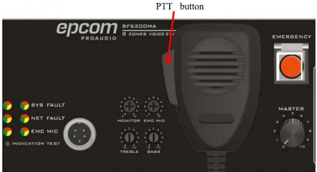
Press the EMERGENCY button, then press the button on the PTT microphone to turn on corresponding zone paging (need configure on PC). You can speak after the reminder tone. Please do not release the button during the speaking or it will automatically turn off paging and make a tone. In emergency mode PTT paging will automatically record and save the action in the TF card.
(Note: PTT has the highest priority in the system, but the host MP3 shared source is a s module, not subject to its intervention.)
5.5 Line detection
Detection accuracy: <25%
Minimum detection power: 10W
Maximum detection power: 500W
Installation of the new device requires sampling the speaker impedance, the specific operation is as follows:
- Install new equipment, connect speakers for each zone.
-
Press impedance detection button on the rear panel, the system will be connected to each zone to sample the load, during sample period can hear during the relay inhalation of the sound, when the lights all off, indicating that the load sampling success.
-
Verify the impedance detection is valid or not:
1) Open circuit detection ---- disconnect any zone output, press system fault self-test button in the front panel until the sound and light self-test is completed, the indicate is orange and computer state is open (open) then connected to the speaker, press the self-test switch, and returned to normal state.
2) Short circuit test ---- Short circuit any zone output, do not need to press system fast self-test button on the front panel. Indicates light is orange and computer status short (short circuit). then connected to the speaker, press the self-test switch, and returned to normal state.
3) Impedance 25% change detection ---- sampling 30W speaker impedance, plus or minus 7W, press system fault self-test button on the front panel, the indicate light is orange and computer status is fault. Then connected to the 30W speaker, press the self-test switch, and returned to normal state.

5.6 Volume control

-
Host volume control is control the volume of the entire machine, the adjustment will af the 1 \~ 8 zone volume. Zone volume adjustment only adjusts the corresponding zone volun does not affect other zones.
-
Amplifier output monitor
Press the MONITOR button to turn on or off the monitor, Light on means amplifier moniturn on, light off means amplifier monitor is turn off.
5.7 IP address Reset

IP address Reset button
Press the IP reset button to reset the host IP address: 192.168.1.253.
5.8 Power-down switching function

24V external power supply interfac
Connect battery of 24V 20A / H or above, 24V DC indicator light is green, when unplug electricity plug, automatically switch to 24V power supply mode.
5.9 Voice Evacuation Router address Settings
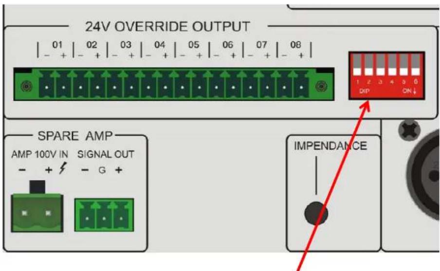
Extended host address switch
✿ Voice Evacuation Router address Table:
| DIP Switch Settings | VoiceEvacuationControllerAddress | |||||||
| 1 | 2 | 3 | 4 | 5 | 6 | 7 | 8 | |
| 1 | 0 | 0 | 0 | 0 | 0 | 0 | 0 | 1 |
| 0 | 1 | 0 | 0 | 0 | 0 | 0 | 0 | 2 |
| 1 | 1 | 0 | 0 | 0 | 0 | 0 | 0 | 3 |
| 0 | 0 | 1 | 0 | 0 | 0 | 0 | 0 | 4 |
| 1 | 0 | 1 | 0 | 0 | 0 | 0 | 0 | 5 |
| 0 | 1 | 1 | 0 | 0 | 0 | 0 | 0 | 6 |
| 1 | 1 | 1 | 0 | 0 | 0 | 0 | 0 | 7 |
| 0 | 0 | 0 | 1 | 0 | 0 | 0 | 0 | 8 |
| 1 | 0 | 0 | 1 | 0 | 0 | 0 | 0 | 9 |
| 0 | 1 | 0 | 1 | 0 | 0 | 0 | 0 | 10 |
| 1 | 1 | 0 | 1 | 0 | 0 | 0 | 0 | 11 |
| 0 | 0 | 1 | 1 | 0 | 0 | 0 | 0 | 12 |
| 1 | 0 | 1 | 1 | 0 | 0 | 0 | 0 | 13 |
| 1 | 1 | 1 | 0 | 0 | 0 | 0 | 14 | |
| 1 | 1 | 1 | 1 | 0 | 0 | 0 | 0 | 15 |
| 0 | 0 | 0 | 0 | 1 | 0 | 0 | 0 | 16 |
| 1 | 0 | 0 | 0 | 1 | 0 | 0 | 0 | 17 |
| 0 | 1 | 0 | 0 | 1 | 0 | 0 | 0 | 18 |
| 1 | 1 | 0 | 0 | 1 | 0 | 0 | 0 | 19 |

- VOICE EVACUATION & PUBLIC ADDRESS SYSTEM
- Contents
- Product renderings
- SF6200MA Product design sketch (2U)
- SF6200MS Product design sketch (2U)
- Main function introduction
- SF6200MA Function feature
- SF6200MS Features
- Main technical parameters Specifications
- Electrical Specifications
- Performance Specifications
- Device function description
- Front panel function description
- Rear panel function description
- Operation Instructions
- Self-test function
- Emergency function
- Local sound source play
- PTT paging
- Line detection
- Volume control
- IP address Reset
- Power-down switching function
- Voice Evacuation Router address Settings
- ✿ Voice Evacuation Router address Table:
Brand : Epcom
Model : SF-6200MA
Category : Receiver