WPC - Audio Martin Audio - Free user manual and instructions
Find the device manual for free WPC Martin Audio in PDF.


| Product Type | Three-way, bi-amp line array element |
| Brand | Martin Audio |
| Model | WPC |
| Frequency Response | 65Hz - 18kHz ±3dB |
| Maximum SPL | 135dB @ 1m |
| LF Drivers | 2 x 10" (250mm) neodymium, Hybrid slot-horn loaded |
| MF Drivers | 2 x 5" (125mm) neodymium, horn loaded |
| HF Drivers | 4 x 0.7" (19mm) neodymium compression drivers, horn loaded |
| System Amplifier | iKON iK42 (4-channel controller amplifier) |
| System Resolution | 1 to 3 enclosures per amplifier channel |
| Nominal Impedance | LF: 8 ohms, MF+HF: 8 ohms |
| Dispersion (Horizontal) | 100° (-6dB), 130° (-10dB) |
| Dispersion (Vertical) | 10° |
| Crossover | 440Hz active, 4.4kHz internal passive |
| Enclosure Material | Multi-laminate birch and poplar plywood |
| Finish | Black textured paint |
| Protective Grille | Black HEX perforated steel |
| Connectors | 2 x Neutrik NL4 (4-pole) |
| Rigging System | 3-point system, inter-cabinet angles 0.5° to 10° |
| Dimensions (W x H x D) | 772mm x 319mm x 421mm (30.4in x 12.6in x 16.6in) |
| Weight | 35 kg (77.1 lbs) |
| Maximum Flown Array | 16 enclosures |
| Accessories (optional) | WPCGRIDt Touring Flying Frame, WPCGRIDi Install Flying Frame, Transport Dolly, Ground Stack Bar, Inclinometer, Rigging Pins |
Frequently Asked Questions - WPC Martin Audio
User questions about WPC Martin Audio
0 question about this device. Answer the ones you know or ask your own.
Ask a new question about this device
Download the instructions for your Audio in PDF format for free! Find your manual WPC - Martin Audio and take your electronic device back in hand. On this page are published all the documents necessary for the use of your device. WPC by Martin Audio.
USER MANUAL WPC Martin Audio
Optimised Line Array
User Guide
natural_image
Exterior view of a black industrial air duct or fan unit with multiple vented blades and mounting flanges (no text or symbols visible)Contents
Introduction: Wavefront Precision....3
About This Manual 3
Amplification, DSP, and Networking....3
Important Safety Instructions....4
CAUTION 4
Unpacking the Units 5
WPC 6
Mechanical Design 7
Acoustic Design....7
Accessories 8
SX118 Subwoofer 8
SX218 Subwoofer 9
iK42 Amplifier 10
Introduction 10
DISPLAY 2.3 Overview....11
Vu-Net 2.1 Overview....17
WPCGRIDt Touring Flying Frame 26
WPCGRIDi Install Flying Frame 27
Transport Dolly for four WPC....28
Ground Stack Bar 28
Inclinometer Assembly 29
Fitting the inclinometer sensor to the Flying Grid....30
Attach the box to the Grid....31
Refit the Lid....31
The Sensor in Position 32
Flown Systems 33
Rigging WPC with the WPCGRIDt Touring Flying Frame 34
Rigging WPC with the WPCGRIDi Install Flying Frame....49
Essential Maintenance 57
WPC - Removing the HF/MF Driver Assembly....57
WPC - Removing a LF Driver 59
SX118 Subwoofer - Replacing the Drive Unit 60
SX218 - Replacing a Drive Unit 62
Introduction: Wavefront Precision
Drawing on the research and technology behind MLA® Series, the Wavefront Precision Series is a new generation of multi-purpose line arrays designed to bring Martin Audio's legendary sound, coverage consistency and control to a broader range of touring applications, installations and budgets.
Wavefront Precision line arrays are designed as complete systems with external iKON® multi-channel amplifiers and optimised by automated DISPLAY™ software.
Adopting the principle of scalable resolution, with external, dedicated multi-channel amplifiers, Wavefront Precision line arrays are uniquely flexible, upgradeable and financially accessible.
With exceptional line array performance guaranteed by the acoustic design itself, scalable resolution unlocks the full potential of a Wavefront Precision array and provides an adaptable pathway into the world of advanced optimisation.
The greater the resolution of the array in terms of individually driven enclosures, the more precisely DISPLAY can fine-tune audience coverage and hold the frequency response and SPLs throughout the venue within a tight window specified by the user.
For the first time in the marketplace the decision on the level of resolution and control that is right for the install, client, event or budget is yours.
About This Manual
This manual explains in detail the individual components that comprise a complete WPC system. System wiring and rigging is explained and the two key software packages are covered. It is not however the intention for this manual to be the sole tutorial medium for those wishing to use the system. Extensive training media is available via the MA website and training webinars are held on a regular basis in order to help you gain a full understanding of the systems and their operation.
Amplification, DSP, and Networking
Wavefront Precision line arrays are designed as complete systems with dedicated, high performance iKON multi-channel Class D amplifiers.
Important Safety Instructions
Read These Instructions
Keep these instructions for future reference
Heed all warnings
Follow all instructions
No naked flame sources such as lighted candles should be placed on the apparatus
Do not block any ventilation openings
Install in accordance with the Martin Audio instructions
Do not install near any heat sources such as radiators, heat registers, stoves or other such apparatus that produce heat
Do not defeat the safety purpose of the grounding-type plug. A grounding plug has two blades and a third grounding prong. The third prong is provided for your safety. If the provided plug does not fit your outlet consult an electrician for replacement of the obsolete outlet.
Protect the power cable from being walked on or pinched particularly at plugs, convenience receptacles, and the point where they exit from the apparatus
This equipment must be earthed
Only use attachments / accessories specified by Martin Audio
Use only with wheelboard and rigging hardware specified by Martin Audio. When moving using supplied wheelboards, caution should be used to avoid injury from the cabinet tipping over
Unplug this apparatus during lightning storms or when unused for long periods of time
No user serviceable parts inside, refer servicing to qualified service personnel. Servicing is required when the apparatus has been damaged in any way such as power supply cord or plug is damaged, liquid has been spilled or objects have fallen into the apparatus, the apparatus has been exposed to rain or moisture, does not operate normally, or has been dropped
Do not remove covers


Do not remove any protective earth or signal cable shield connections
CAUTION
To reduce the risk of electric shock do not remove any covers. There are no user serviceable parts inside the units. Refer servicing to qualified service personnel only. Call Martin Audio Ltd on +44 (0) 1494 535312 or e-mail info@martin-audio.com for service.
Unpacking the Units
After unpacking the unit, please check it carefully for any damage. If any is found, immediately notify the carrier concerned – you, the consignee, must instigate any claim. Please retain all packaging in case you need to return the unit.
Please think of the environment.
When the product has reached the end of its useful life, please dispose of it responsibly through a recycling centre.
WPC
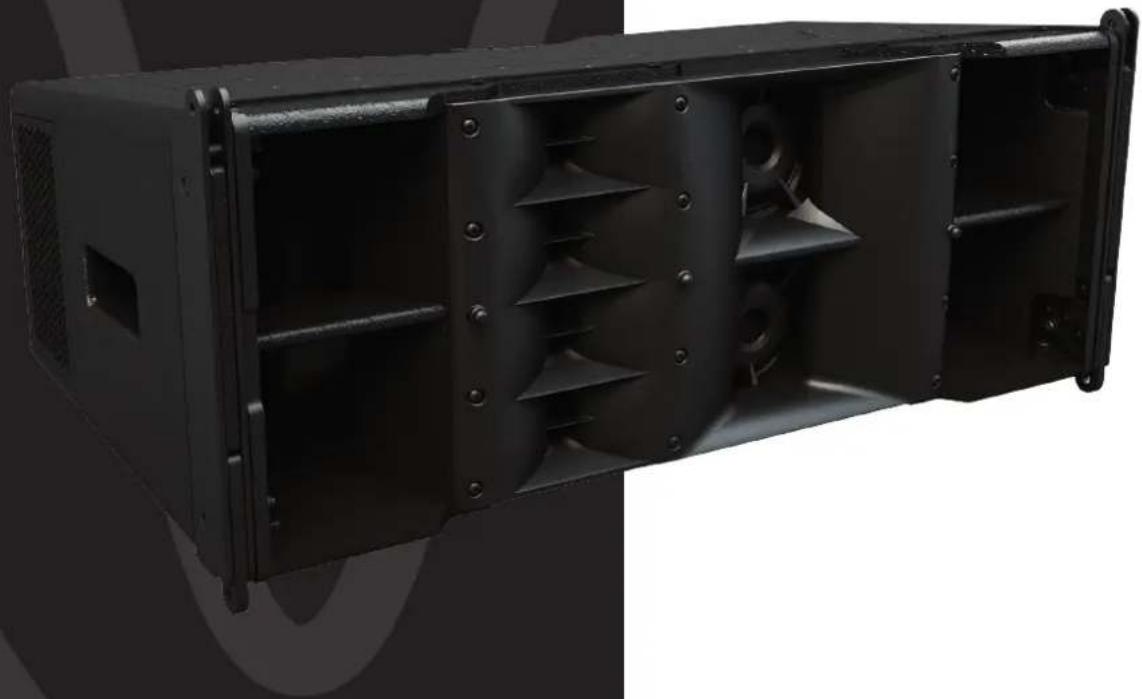
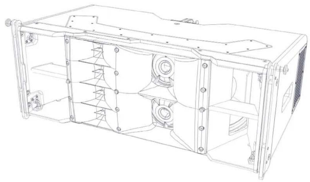
WPC is a three-way passive compact line array element consisting of two 10" neodymium magnet low frequency drivers in a Hybrid configuration, two 5" neodymium magnet mid frequency drivers, and four 0.7" neodymium magnet high frequency compression drivers loaded by constant directivity waveguides. In conjunction with automated DISPLAY system design and Vu-Net network control software applications, WPC features scalable resolution for advanced array control, resulting in outstanding levels of consistent, high quality audio that can be distributed to every point throughout the audience in a venue.
natural_image
Technical line drawing of a mechanical device casing with internal components (no text or symbols)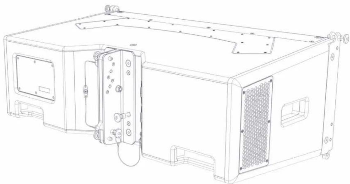
natural_image
Technical line drawing of a mechanical device with mounting flanges and internal components (no text or symbols)The WPC is a new breed of medium-format optimised line array which brings innovative acoustic design, ultra-high performance and coverage consistency to a wider range of users, applications and budgets than previously possible. A three-way, bi-amp system, it features horn-loaded low-frequency, mid and HF sections to raise efficiency and increase output. Its high efficiency acoustic design can equal or outperform larger, direct radiator systems — a 12-box array will throw beyond 60 metres (200ft) and deliver impressive rock levels to a 5,000-seat venue, saving on truck space and weight.
Mechanical Design
WPC is designed mechanically to be an easy to handle, quick to rig, safe, rugged and stable touring loudspeaker. The cabinet is constructed predominantly from high grade multi-laminate birch and poplar plywood, with an integral 3-point rigging system. Two side pocket handles and two rear grip handles make handling safe and easy, and the cabinet is finished in black textured paint with a fabric-backed protective steel grille.
Acoustic Design
The WPC's low frequency section consists of 2 x 10" (250mm) neodymium drivers in a Hybrid® configuration which marries the benefits of horn and reflex loading. Each driver is slot-loaded into a short horn to give a high sensitivity of 103dB @ 1m/2.83V, while the rear of the driver is reflex-loaded to extend the LF output. The punch and low-frequency extension produced from such a small enclosure volume are remarkable.
Mid and HF horns are physically separate — a key factor in the WPC's exemplary 100° horizontal constant directivity dispersion pattern. The midrange horn design utilises 2 x 5" (125mm) neodymium drivers to produce a high SPL of 109dB @ 1m/2.83V, while the HF section employs 4 x 0.7" (19mm) exit neodymium compression drivers which feed four individual horns. Use of multiple small HF drivers instead of a more traditionally-used large format compression driver results in less distortion and a more extended HF response.
Accessories
SX118 Subwoofer
natural_image
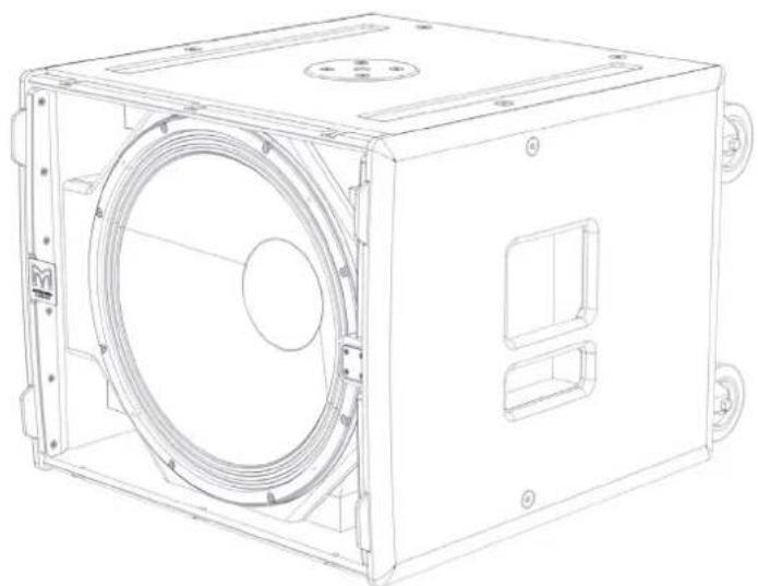
Technical line drawing of a mechanical enclosure with circular and rectangular components (no text or symbols)The SX118 is a compact, high performance subwoofer that extends the low frequency operating range of the WPC system to 47Hz and provides exceptional low frequency output for such a compact enclosure. It features a long excursion 18" (460mm) / 4" (100mm) voice coil driver with a water-resistant cone and triple roll surround in a compact reflex enclosure.
natural_image
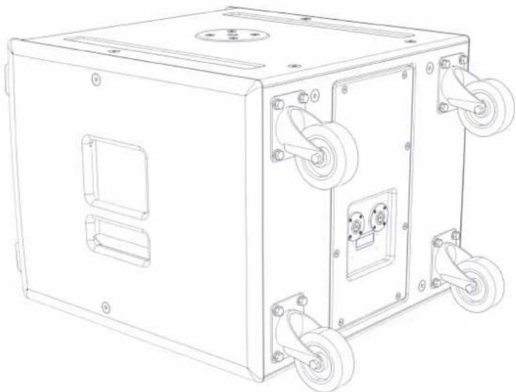
Technical line drawing of a mechanical device with wheels and mounting holes (no text or symbols)The design of the 18" driver maximises output while minimising power compression and distortion, and the four reflex ports have a large frontal area to reduce turbulent air noise at very high levels. The enclosure is constructed from multi-laminate birch ply, finished with a durable textured coating and equipped with a steel grille, twin grab handles, skids, flying inserts for installation and a threaded pole socket.
SX218 Subwoofer
natural_image
Technical line drawing of a mechanical enclosure with two circular fans and mounting holes (no text or symbols)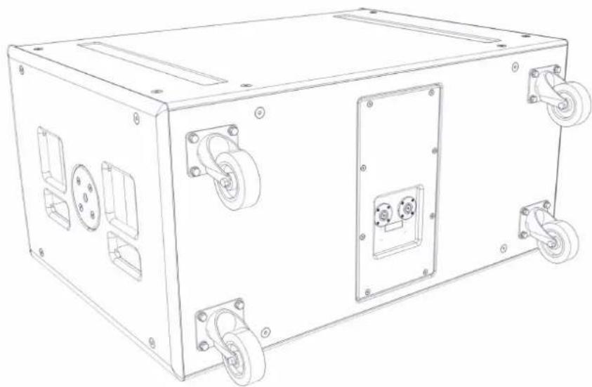
natural_image
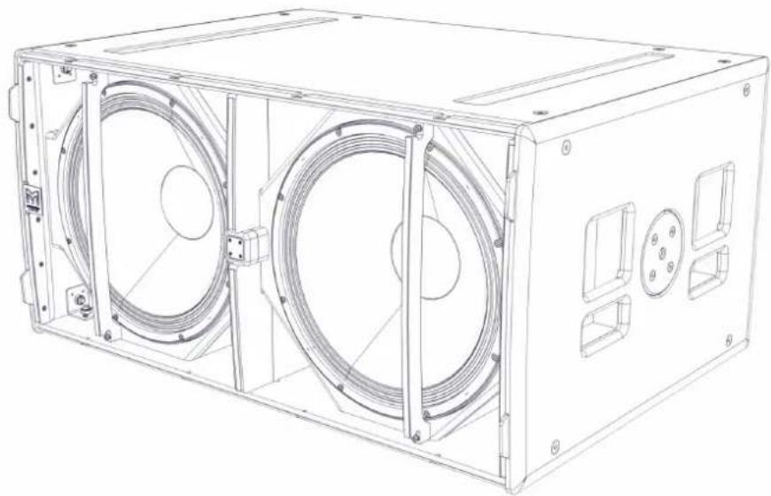
Line drawing of a mechanical device with wheels and mounting holes (no text or symbols)The SX218 is a compact, high performance subwoofer that extends the low frequency operating range of the WPC system to 35Hz and provides exceptional low frequency output for such a compact enclosure. It features two long excursion 18" (460mm) / 4" (100mm) voice coil drivers with water-resistant cones and triple roll surrounds in a compact reflex enclosure.
The design of the 18" drivers maximises output while minimising power compression and distortion, and the eight reflex ports have a large frontal area to reduce turbulent air noise at very high levels. The enclosure is constructed from multi-laminate birch ply, finished with a durable textured coating and equipped with a steel grille, four grab handles, skids, and flying inserts for installation.
iK42 Amplifier
Introduction
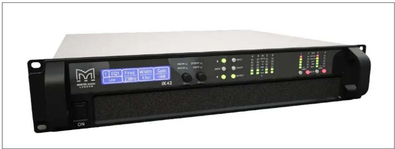
The iKON iK42 is an advanced 4-channel controller amplifier which combines very high power density with superb audio performance, state-of-the-art DSP and network control for WPC systems.
The iK42 can deliver a full 5000 watts per channel into 2 ohms with all channels driven while remaining highly efficient. Its high efficiency reduces the energy drawn from the mains supply and ensures the power reserves needed to deliver superb sound under arduous live conditions.
Ethernet is used for system remote control and monitoring via Martin Audio's Vu-Net software application, while a user-friendly front panel interface allows full local control of all features. Dante digital audio network inputs are also provided for digital audio distribution and control.
Powerful DSP is fully integrated into the iK42 to provide a multitude of features that ensure maximum performance and worldwide compatibility. It also provides up to 1000 FIR filter taps @ 48kHz on each output channel, which is essential to implement DISPLAY's wide bandwidth optimisation process in WPC line array systems. The iK42 employs comprehensive protection functions to maintain safe operating conditions of both the amplifier and the loudspeakers driven — including a sophisticated loudspeaker limiter suite which incorporates peak, RMS and excursion limiting, as well as multiband limiting for passive 2-way systems.
DISPLAY 2.3 Overview
DISPLAY 2.3 is a unique software application for Wavefront Precision systems which calculates both inter-cabinet splay angles and the DSP parameters for optimum system performance in any given space. Unlike competitors systems which generally use a basic geometric calculation to aim their arrays, DISPLAY uses a completely revolutionary approach using an extremely accurate computer model of the array to analyse the system performance in a drawing of the venue to precisely calculate the parameters for the system to get exactly the coverage you have specified. As a system designer you get to determine exactly how you would like the system to perform in the space; the spl contour from the front to the back of your audience region, how much spill into non-audience areas is acceptable and even specify designated “hard-avoid” areas that the system will actively process to reduce spill to a minimum - great for producing a quiet stage or for reducing noise pollution off-site at outdoor events.
The application is very straightforward to use taking you through a series of steps in a logical order. In fact it won't allow you to attempt to design a system in the wrong order; steps need to be completed one after the other in the correct order making it very straightforward to design an array that will perform to its maximum potential.

DISPLAY opens with a Dashboard at the top of the screen the initial view prompting you to specify your array which is the first step of the design process. WPC or WPM are available along with the Multicellular family of products. You next specify how your array will be deployed: flown, or ground stacked; specify the number of cabinets and give the array a name.
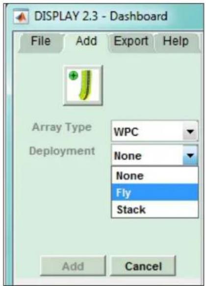
The dashboard changes to show the tabs from left and right in the order in which the design will be completed.

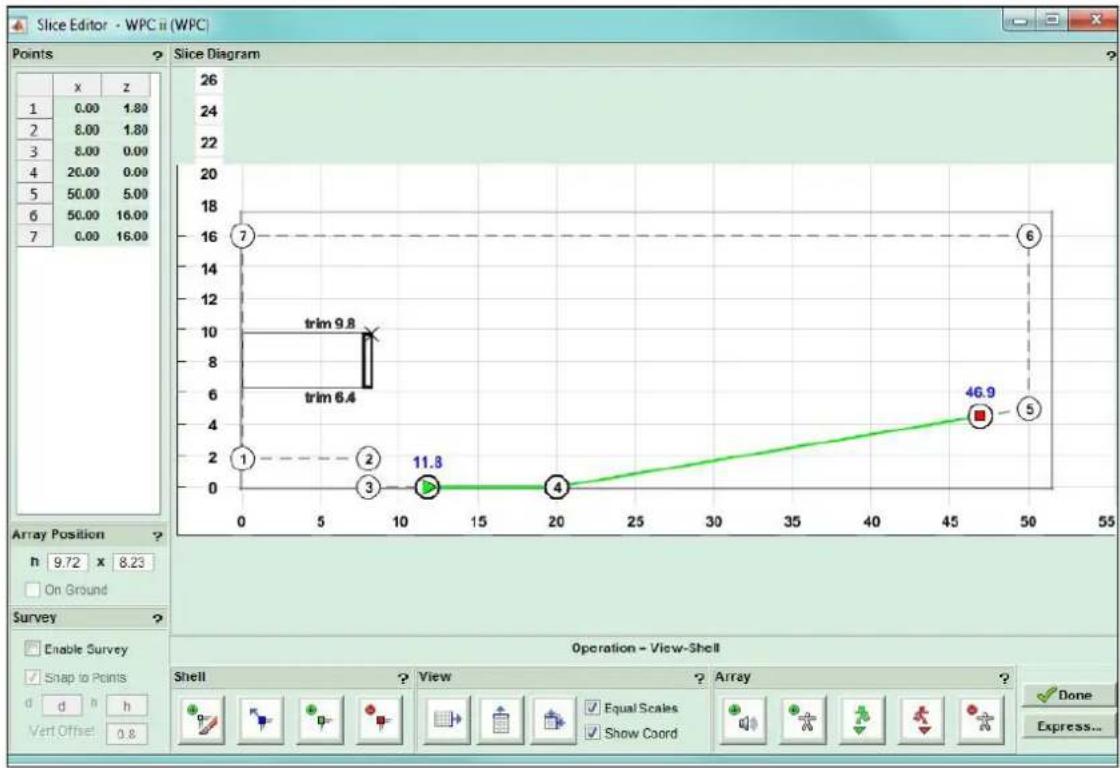
First a 2D slice of the venue is created, the Coverage within the venue is specified, the splay angles calculated. A rigging report allows you to deploy the array and whilst that is being done the EQ coefficients are calculated. Finally an SPL report gives detailed information showing exactly how the system will perform. The computer model is accurate to within +/- 1dB of actual measured results so the spl tab is a reliable overview of how well your system design will cover the space.
line
Operation - View-Shell | Point | X | Y | |-------|------|------| | 1 | 9.72 | 11.8 | | 2 | 9.72 | 11.8 | | 3 | 9.72 | 11.8 | | 4 | 9.72 | 11.8 | | 5 | 9.72 | 11.8 | | 6 | 9.72 | 11.8 | | 7 | 9.72 | 11.8 | | 8 | 9.72 | 11.8 | | 9 | 9.72 | 11.8 | | 10 | 9.72 | 11.8 | | 11 | 9.72 | 11.8 | | 12 | 9.72 | 11.8 | | 13 | 9.72 | 11.8 | | 14 | 9.72 | 11.8 | | 15 | 9.72 | 11.8 | | 16 | 9.72 | 11.8 | | 17 | 9.72 | 11.8 | | 18 | 9.72 | 11.8 | | 19 | 9.72 | 11.8 | | 20 | 9.72 | 11.8 | | 21 | 9.72 | 11.8 | | 22 | 9.72 | 11.8 | | 23 | 9.72 | 11.8 | | 24 | 9.72 | 11.8 | | 25 | 9.72 | 11.8 | | 26 | 9.72 | 11.8 | | 27 | 9.72 | 11.8 | | 28 | 9.72 | 11.8 | | 29 | 9.72 | 11.8 | | 30 | 9.72 | 11.8 | | 31 | 9.72 | 11.8 | | 32 | 9.72 | 11.8 | | 33 | 9.72 | 11.8 | | 34 | 9.72 | 11.8 | | 35 | 9.72 | 11.8 | | 36 | 9.72 | 11.8 | | 37 | 9.72 | 11.8 | | 38 | 9.72 | 11.8 | | 39 | 9.72 | 11.8 | | 40 | 9.72 | 11.8 | | 41 | 9.72 | 11.8 | | 42 | 9.72 | 11.8 | | 43 | 9.72 | 11.8 | | 44 | 9.72 | 11.8 | | 45 | 9.72 | 46.9 | | 46 | | | | | | | | | | | | | | | | | | | | | | | | | | | | | | | | | | | | | | | | | | | | | | | | | | | | | | | | | | | | | H: | | | | X: | Z: | Function: Slice Diagram Array Position: Array View: Operation Array: Operation Check: Enable Survey Snap to Points Vert Offset: Vert Offset Equal Scales Show Coord Done Express...The 2D slice is either drawn from scratch or you can also import a shell drawing from a previous project if you are working in a venue you have visited previously. The slice is a side view of the venue. It is drawn anticlockwise starting at the back of the stage and clicking to define the position of vertices that define all of the planes within the venue. This doesn't have to be done accurately as you can refine the precise position of the points working from architects drawings or measurements you have taken yourself. The array is positioned and the audience region specified from start to finish.
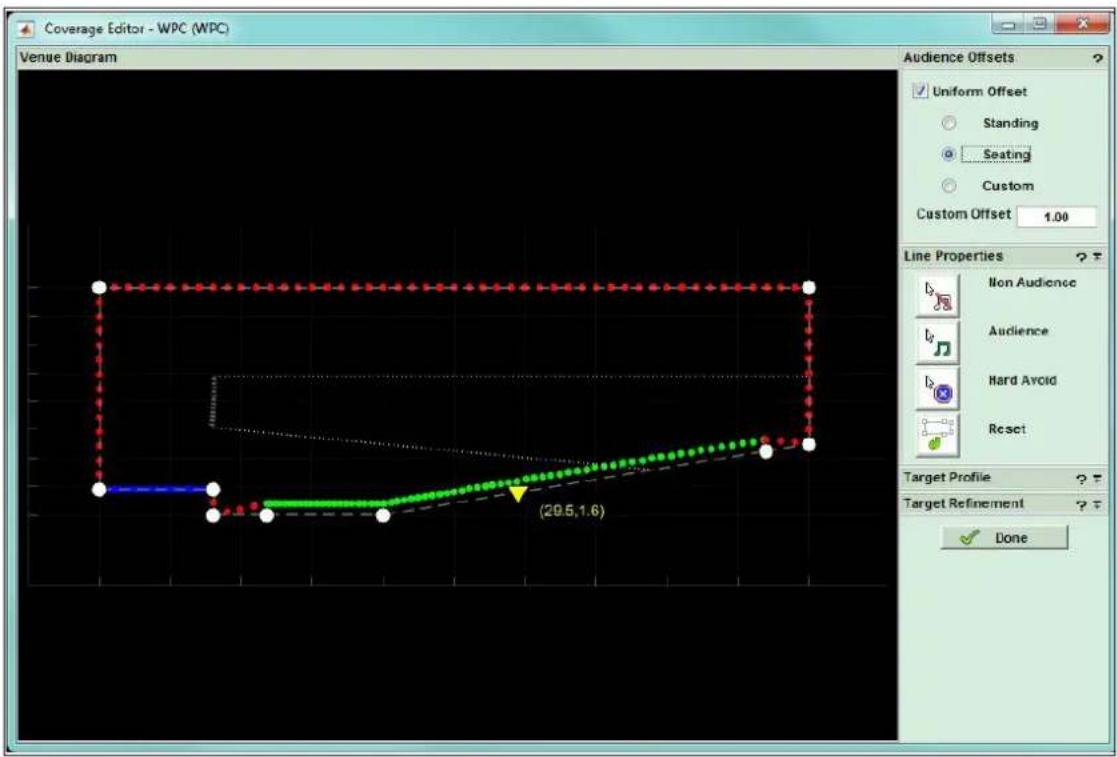
The coverage tab shows your 2D model with the planes refined into three types;-audience in green, non-audience in red and hard avoid in blue. Each dot represents a virtual microphone position at which the software will take response measurements using the integral computer model. The dots in the critical audience region are closer together for greater accuracy and are spaced closer together at the start of the audience region to mirror how each region is covered by sections of the array. The audience offset can be edited; standing, sitting or a custom offset of your choice and each region can be edited, perhaps changing a section under a balcony from audience to non-audience for example. The spl profile can be modified and the environmental conditions entered to allow optimisation to compensate for air absorption, particularly critical for outdoor events.
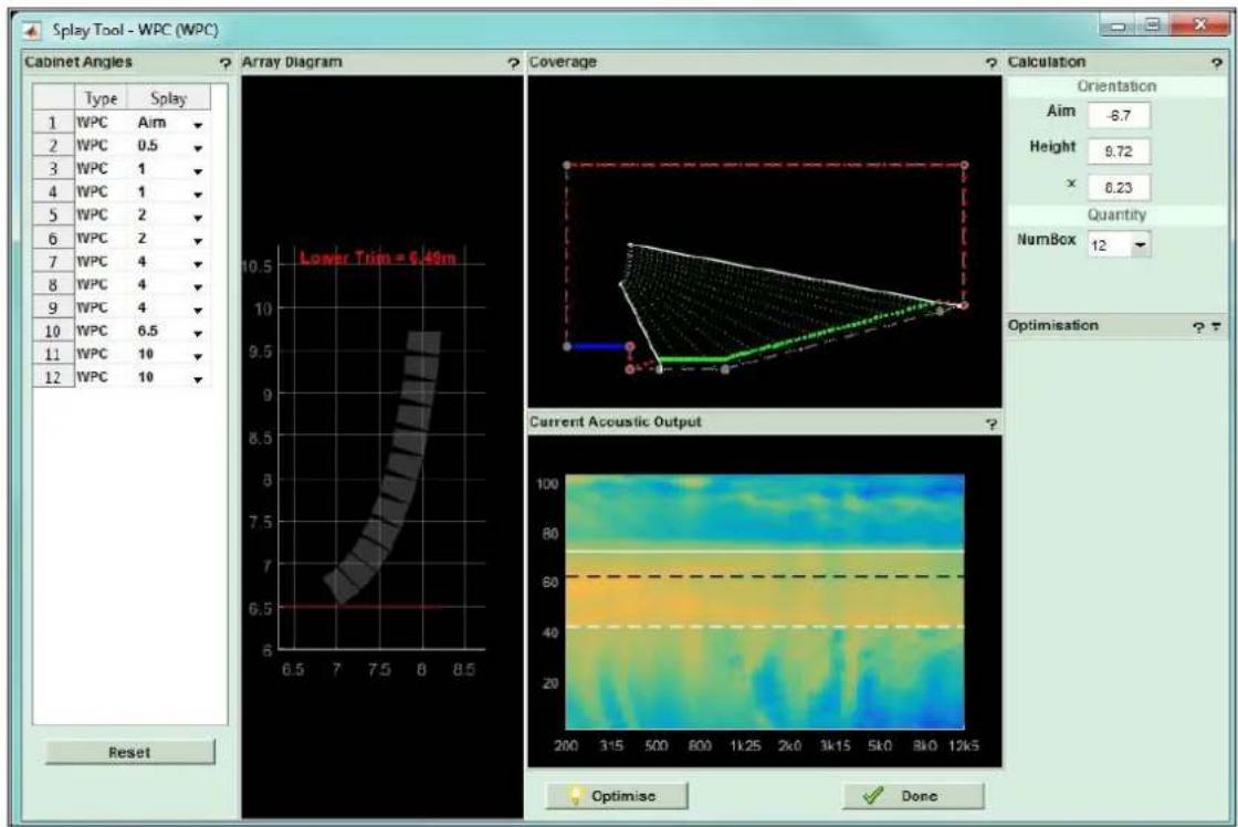
In the splay tab you can refine the quantity and position of the array before the system optimises the inter-cabinet splay angles and the "aim" angle for the flying grid.
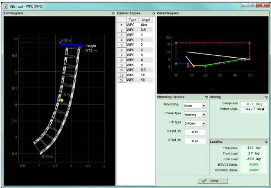
Once this is complete you can further refine how the array is to be deployed in the Rig tab; choosing for example between a 2 point hang and a single point for which the application will display the best position on the flying frame to give the nearest angle to the optimised aim. The actual physical angle that the specified hole in the frame will give will be displayed with the option to use this angle in the optimisation so that the array EQ is optimised for the actual physical position in which the array is installed.
Finally the load on each flying point is shown and critically the Rig tab shows if the array is safe and meets both BGVC1 and DIN18800 standards.
line
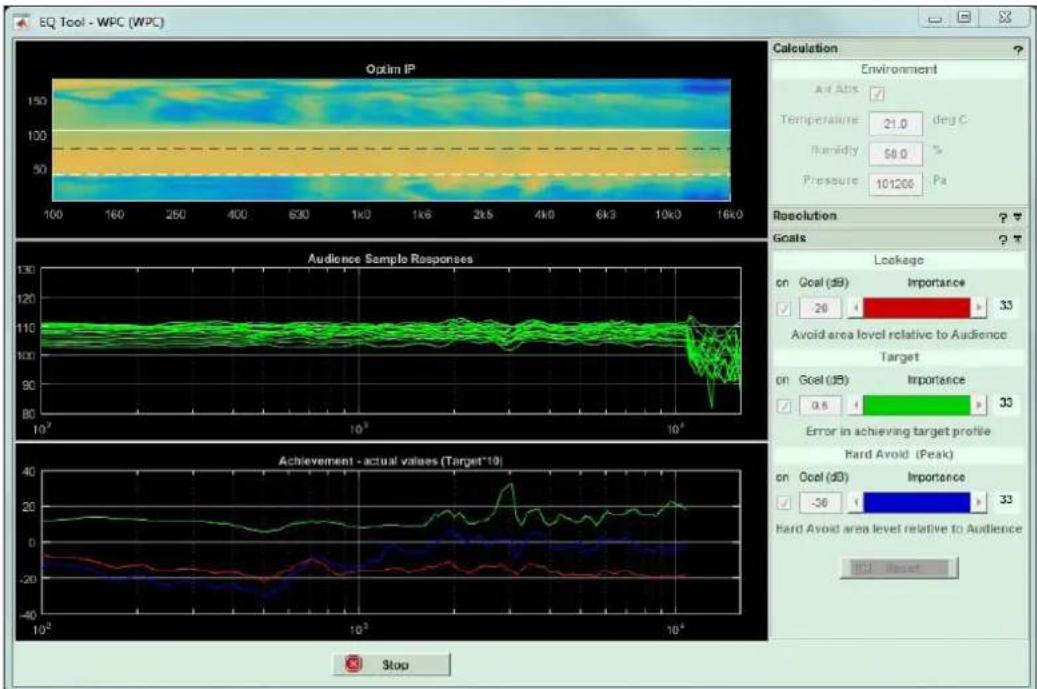
| Metric | Value | |--------|-------| | Accuracy | 21.0 | | Humidity | 50.0 | | Pressure | 101206 | | Goal | 33 | | Exposure | 0.5 | | Area Level Relative to Audience Target | 33 | | Error in Achieving Target Profile | -30 | | Hard Avoid (Peak) | 33 | | Hard Avoid area level relative to Audience (WPC Reset) | Reset |With the physical deployment underway you can progress to optimise the EQ. Again you can enter the environmental conditions and can balance the three goals of response in your audience region, leakage to non-audience and the hard avoid performance. By default each are given equal importance but if your application demands particular emphasis on any one of these parameters they can be given greater importance.
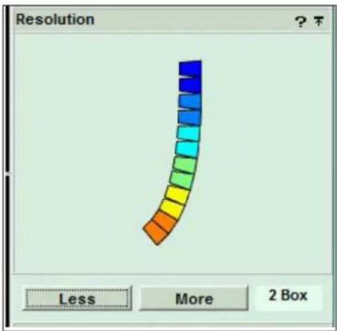
The Resolution is entered 1 to 3 box for WPC.
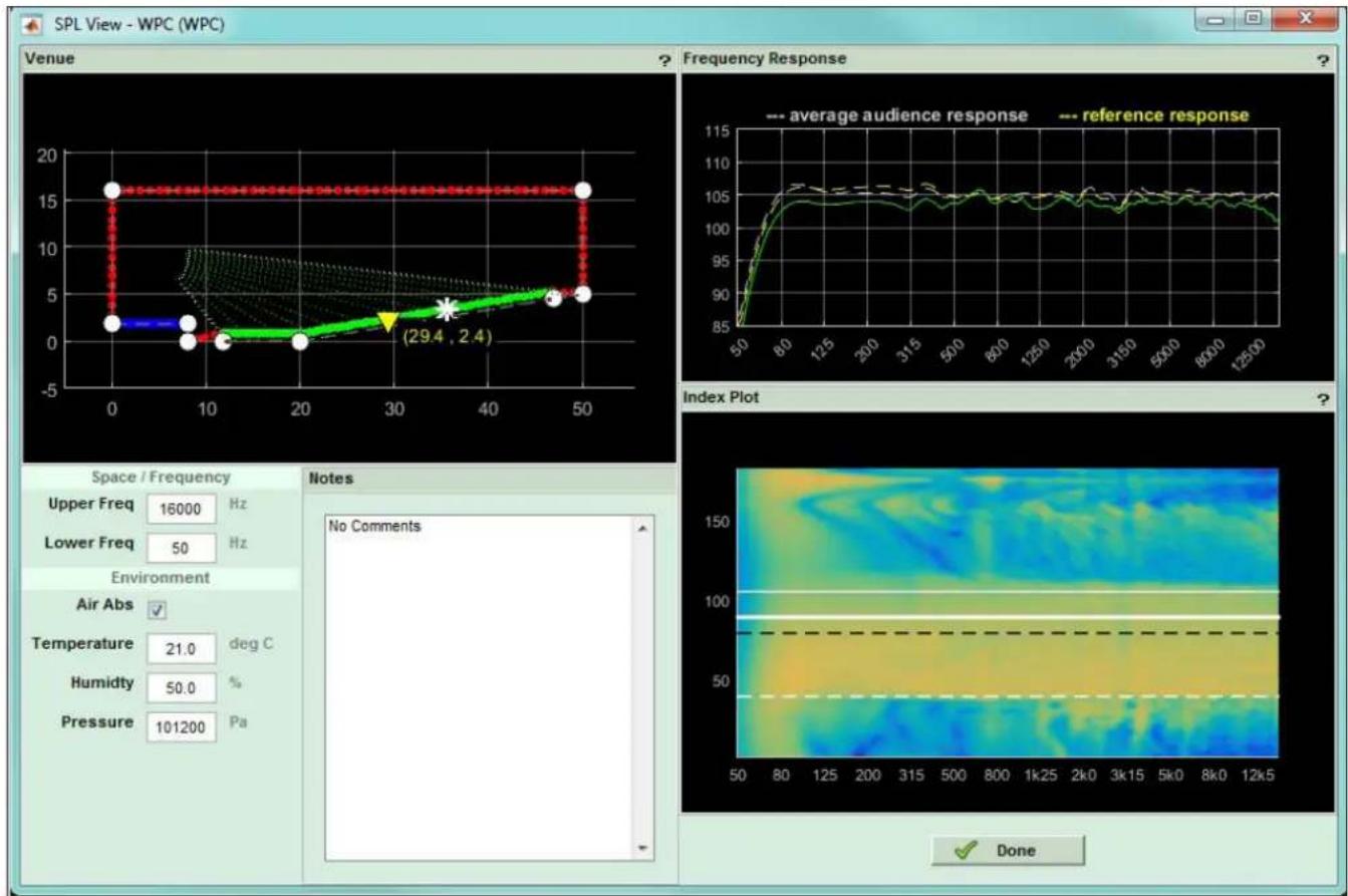
The Spl tab shows the system performance. The entire venue spl is displayed on an index plot with frequency along the horizontal axis and position within the venue along the vertical. Spl is indicated with colour, blue being quietest moving through the colour spectrum to red which is the loudest. You can move the cursor around the Index Plot and the position is shown on the 2D slice of the venue top left whilst showing the frequency response at that position on the graph on the right.
The final stage is to export your design. You can produce a printable rigging report, a wire-frame 3D model of the array, export 3D data for use with EASE and most importantly export the project as a D2P file which can be uploaded directly to an iKon amplifier for powering Wavefront Precision systems.
DISPLAY 2.3 can be downloaded from the Martin audio website here:- https://martin-audio.com/support/software. There is also a comprehensive User Guide to take you through the design process in detail. We strongly recommend downloading the User Guide to fully understand the application.
Vu-Net 2.1 Overview
Vu-Net is Martin Audio's application which is used to connect to iKon amplifiers and a growing number of products including the MLA family, CDD-Live, PSX and DD12. This makes it possible to create a system with products from several different ranges and control and monitor them from a single software platform.
Connection to iKon amplifiers is made over a standard Ethernet network using off the shelf networking products so remote access to control Wavefront Precision systems is extremely straightforward. Complex systems with large numbers of amplifiers can easily be created using standard network switches, the system by default is configured with dynamic IP addressing so DHCP support will be required however a static IP configuration is also easily enabled.
Vu-Net is used to upload the presets created using DISPLAY 2.3 into the amplifiers which will automatically create a thumbnail of the Wavefront Precision array that has been designed. Once the array has been created, all of the amplifier functions are available for control to make any changes you may need to routing, crossover point, phase, delay or system EQ. The application has an intuitive GUI making is very quick and easy to get to grips with if you have used any computer based processing software. Once the system is configured the amplifiers can be kept on-line to give comprehensive monitoring of the system performance.
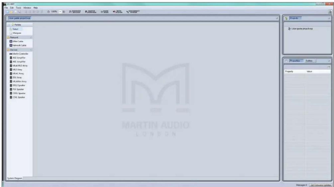
The application opens with a blank System diagram. It is possible to add products manually using the Palette on the left but this has limited use, in practical applications, the Discover Devices button is used.

The application searches the network for all Vu-Net enabled devices and will run an installation wizard to add them to the Vu-Net project.
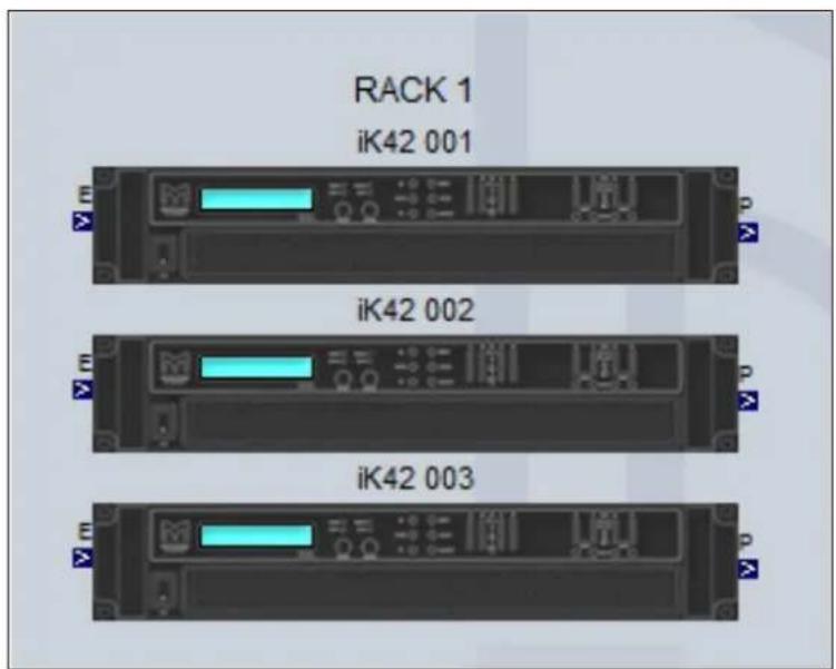
The next stage is to right click on the amplifiers to access the Preset Manager.
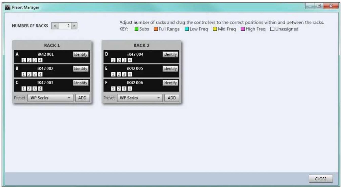
From here the system allows you up upload the D2P file of your system design.
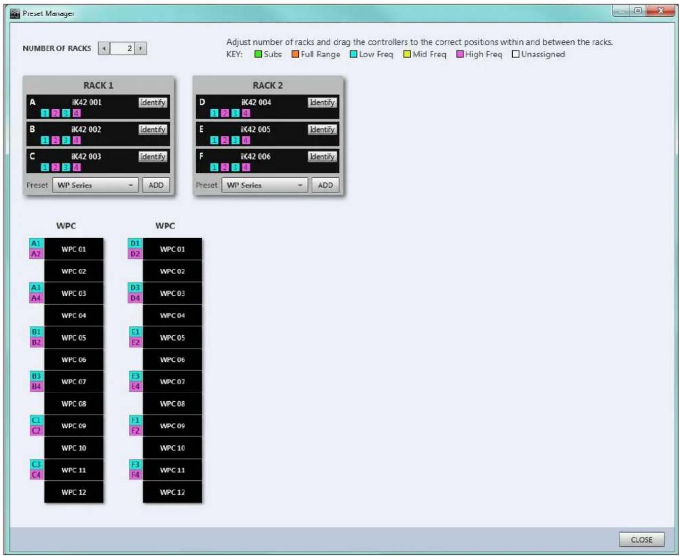
You can now return to the project system diagram, double click on the amplifiers and edit the system to suit your application, perhaps adding some delay to align subwoofers.
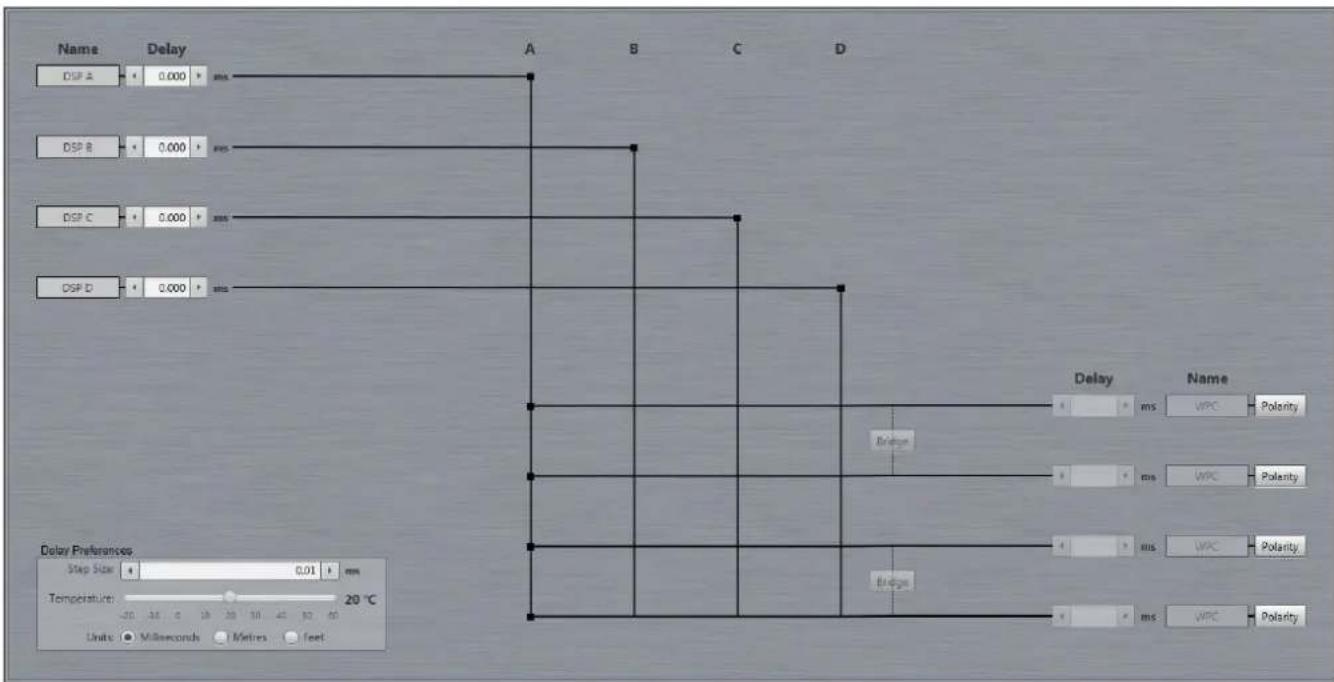
flowchart
graph TD
    A["Name DSP A"] --> B["Delay: 0.000 ms"]
    C["Name DSP B"] --> D["Delay: 0.000 ms"]
    E["Name DSP C"] --> F["Delay: 0.000 ms"]
    G["Name DSP D"] --> H["Delay: 0.000 ms"]
    B --> I["A"]
    D --> J["B"]
    F --> K["C"]
    H --> L["D"]
    I --> M["Delay: ms WPC Polarity"]
    J --> N["Delay: ms WPC Polarity"]
    K --> O["Delay: ms WPC Polarity"]
    L --> P["Delay: ms WPC Polarity"]
    M --> Q["Delay: ms WPC Polarity"]
    N --> R["Delay: ms WPC Polarity"]
    O --> S["Delay: ms WPC Polarity"]
    P --> T["Delay: ms WPC Polarity"]
    Q --> U["Delay: ms WPC Polarity"]
    R --> V["Delay: ms WPC Polarity"]
    S --> W["Delay: ms WPC Polarity"]
    T --> X["Delay: ms WPC Polarity"]
    U --> Y["Delay: ms WPC Polarity"]
    V --> Z["Delay: ms WPC Polarity"]
    W --> AA["Delay: ms WPC Polarity"]
    X --> AB["Delay: ms WPC Polarity"]
    Y --> AC["Delay: ms WPC Polarity"]
    Z --> AD["Delay: ms WPC Polarity"]
Input EQ can be adjusted to suit your preferences and to compensate for any difficult acoustics.
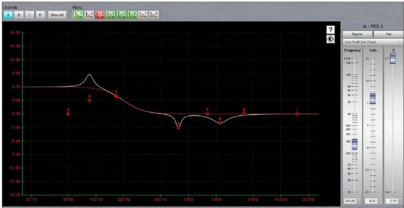
line
| Frequency | Value (dB) | | --------- | ---------- | | 200 Hz | 6.0 | | 100 Hz | 5.0 | | 200 Hz | 3.0 | | 1 kHz | -3.0 | | 2 kHz | -2.5 | | 5 kHz | -1.0 | | 20 kHz | 0.0 |The output EQ is greyed out as it is used to apply the EQ created by your DISPLAY project, however the high pass filter is available for adjustment so you can determine the crossover point between the WPC array and your subwoofers.
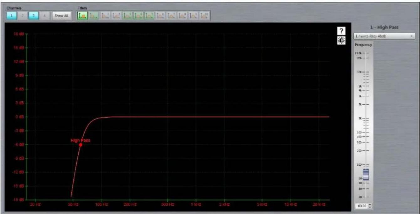
line
| Frequency | Gain (dB) | | --------- | --------- | | 50 Hz | -6 |Comprehensive ganging is available so you can ensure that stereo arrays remain completely identical.
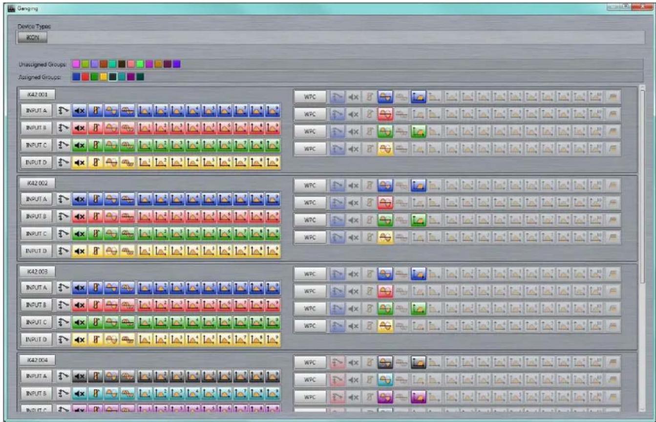
Once the system is configured to your satisfaction a Master Overview gives a complete picture of even the most complex system allowing you to monitor all metering and access commonly needed functions such as gain and mute.
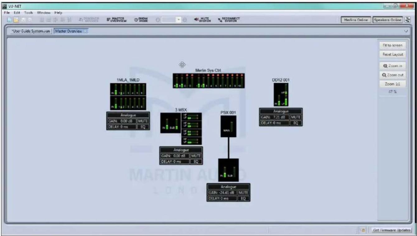
Vu-Net is a free download from the Software page of the Martin Audio website here; https://martin-audio.com/support/software
It is a comprehensive application with a host of functions to enable control and monitoring of almost every parameter of a system. For full details we would strongly recommend downloading the Vu-Net User Guide which can be found on the same page as the application download, this is an excellent reference to fully understand the use of Vu-Net.
Rigging WPC
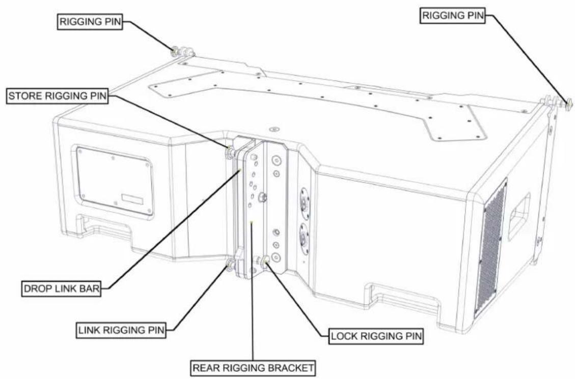
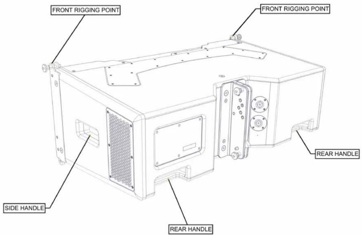
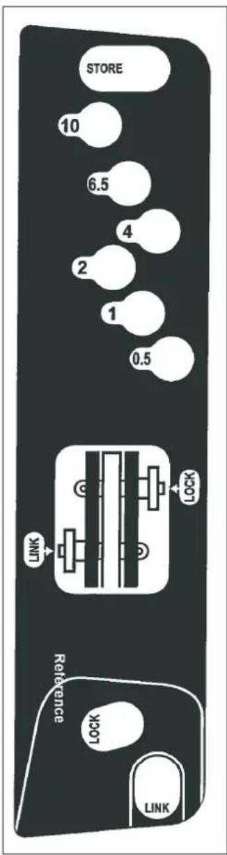
WPC's three-point rigging system consists of two rigging points at the front and a single rigging point at the rear of the cabinet. The rear rigging bracket assembly provides six rigging holes allowing for inter-cabinet angles of 0.5^ , 1^ , 2^ , 4^ , 6.5^ and 10^ , as well as STORE, LOCK, and LINK positions, for flying arrays or for use when assembling ground stacked arrays.
WPC Connections
The WPC has two parallel-wired Neutrik® NL4 connectors on an angled panel at the rear of the cabinet, recessed to avoid damage. Connect speaker cables here, taking care to observe the colour coding of the connectors.
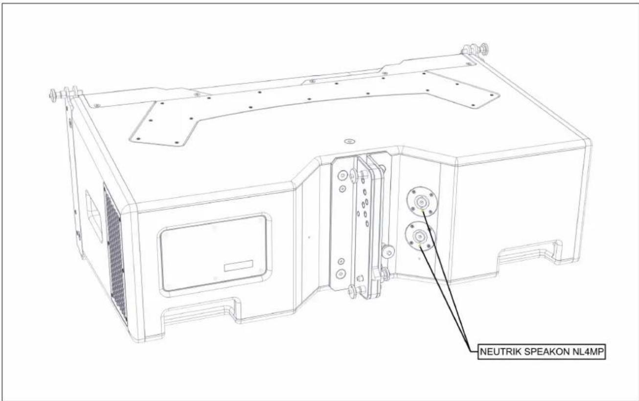
The two NL4s are wired in parallel so either can be used as a nominal 'input' or 'link' output. Since WPC is a bi-amped system all speaker cables and link cables must utilise 4-core cable. When the system is configured for a single box resolution system each cabinet is connected to two amplifier channels. In two box or higher resolution, connection is made from an amplifier channel to the 'input' of one cabinet and the second 'link' NL4 is used to make a parallel connection to an adjacent cabinet. The maximum is three box resolution with three cabinets connected to two amplifier channels (one for LF one for HF). Connection goes to one cabinet with links between the two cabinets below in daisy-chain fashion going from link out to input on the next cabinet.
WPCGRIDt Touring Flying Frame
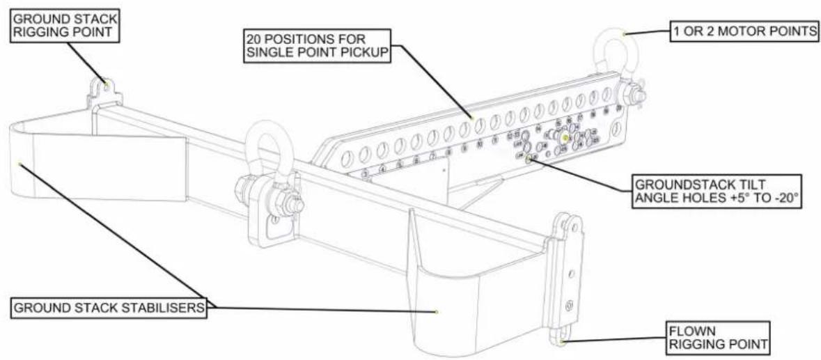
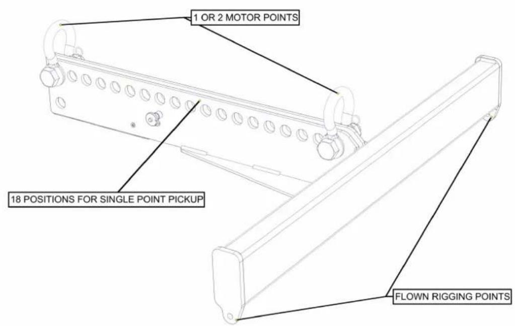
The Touring Flying Frame is a comprehensively featured Flying Frame designed to meet BGVC1 and DIN18800 standards, and capable of lifting up to a maximum of 16 WPC cabinets using either one or two lift points, allowing both positive (up-tilt) and negative (down-tilt) array tilt angles.
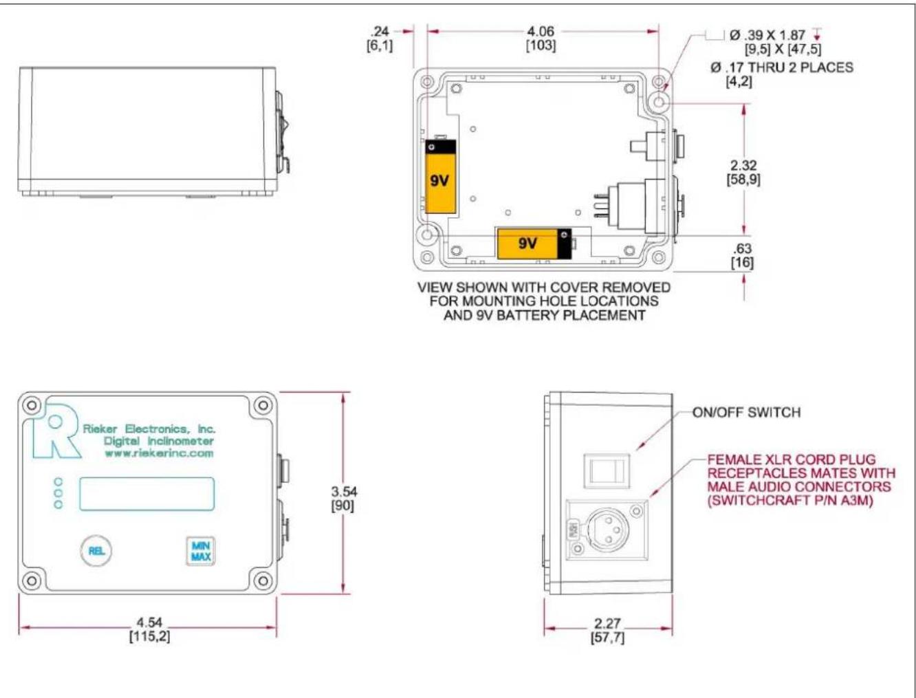
An inclinometer is available for use with the Touring Flying Frame which checks the angle at which the WPC array is flown at (relative to the horizontal). It consists of a sensor part number ASM20017 (mounted within the Flying Frame, one required per grid) and a remote display unit part number ASM20019. Interconnection is via a standard XLR mic cable.
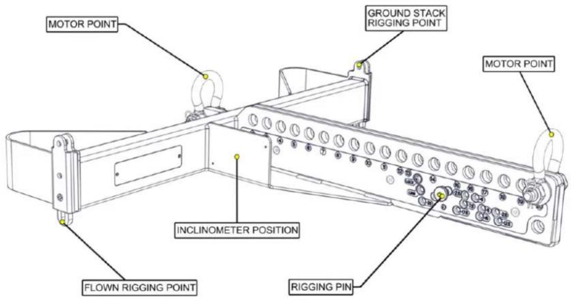
WPCGRIDi Install Flying Frame
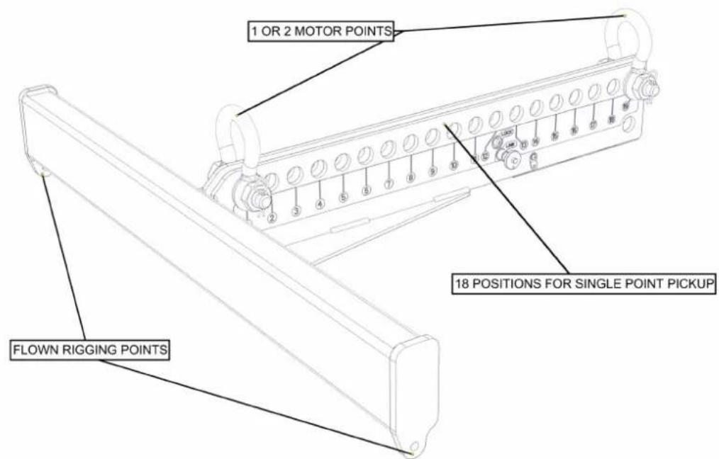
The Install Flying Frame provides a cost effective rigging solution and simplicity of operation for permanently flown installations. It is designed to meet BGVC1 and DIN18800 standards, and will lift a maximum of 16 WPC cabinets using either two lift points or a single lift point, in which case the lift point position is determined by the Martin Audio DISPLAY software.
Transport Dolly for four WPC
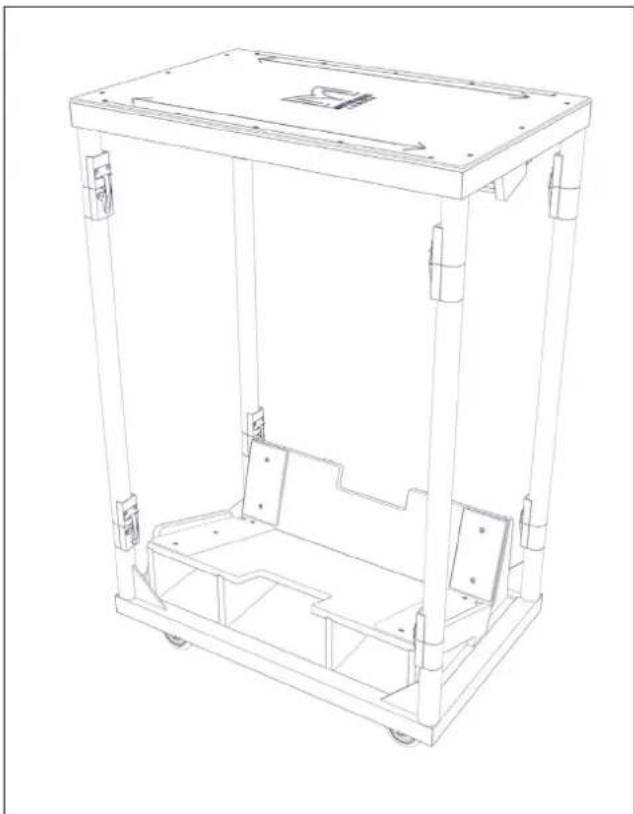
An optional, dedicated Transport Dolly is available to house an array of four WPC cabinets. This will allow safe transportation and convenient rigging and de-rigging if your system is to be portable
natural_image
Line drawing of a mechanical chassis with frame and wheels (no text or symbols)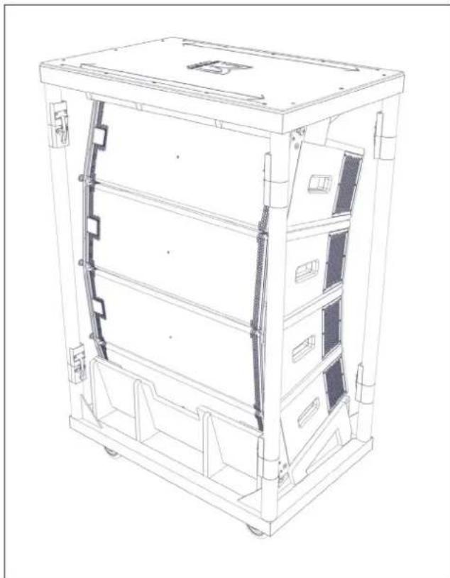
natural_image
Technical line drawing of a multi-chamber electronic device chassis (no text or symbols)Ground Stack Bar
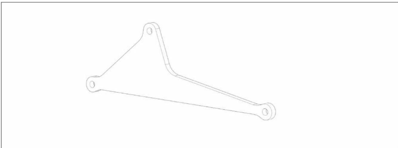
This precision alignment bar is used in conjunction with the Touring Flying Frame to define the angle between the WPC array and the Flying Frame when the system is configured for ground stacking. Depending on where the Ground Stack Bar is attached to the Touring Flying Frame, a range of aiming angles from +5^ to -20^ can be achieved.
natural_image
Line drawing of a three-legged mechanical bracket (no text or symbols)Inclinometer Assembly
Martin Audio supplies an optional remote angle monitoring system which can be used to reliably check the angle at which the WPC array is flown at (relative to the horizontal). It consists of a sensor (mounted within the Flying Frame) and a remote display unit. Interconnection is via a standard XLR mic cable.
Fitting the inclinometer sensor to the Flying Grid
The WPC touring flying grid may be fitted with an inclinometer sensor which is available as an optional accessory part number ASM20017. Once coupled with the ASM20019 inclinometer read-out display via a standard 3-pin XLR mic cable, precise measurements of the angle of the array can be taken to ensure that the DISPLAY optimisation is as accurate as possible.
The touring frame part number WPCGRIDT has a mounting bracket with M4 threaded holes ready to accept the sensor which is housed in a rugged weatherproof diecast aluminium enclosure. Fitting the sensor is a very quick and easy job requiring just two tools, a 3mm Allen Key (wrench) and a PZ2 Pozidrive screwdriver.
Remove the Lid
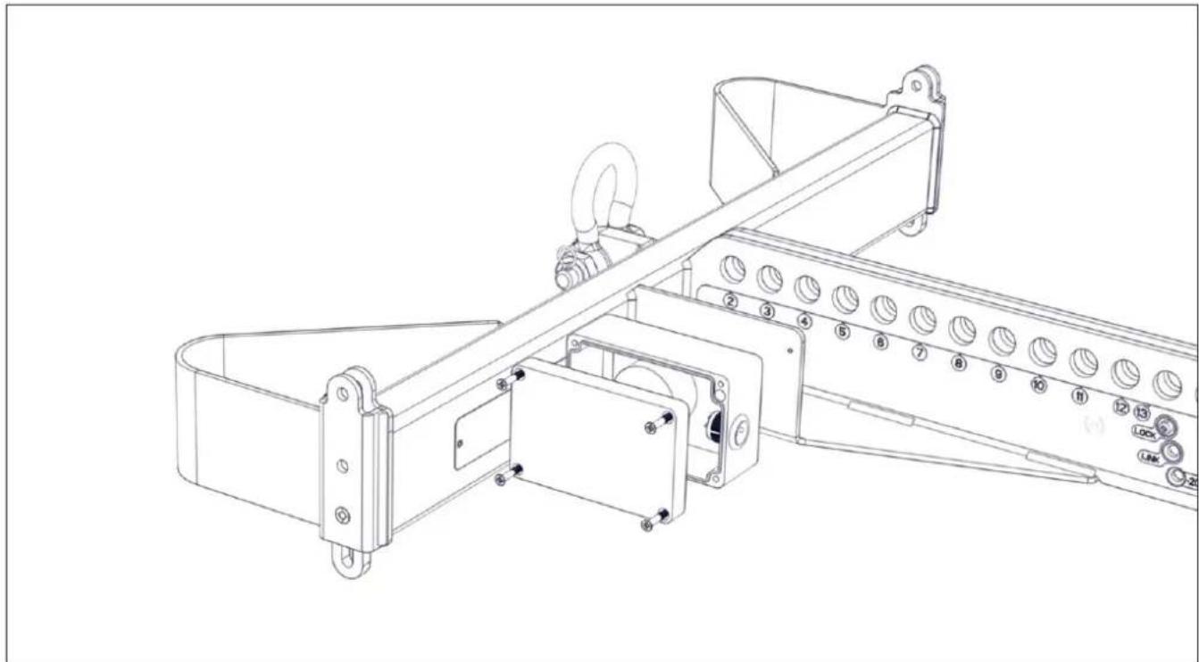
The sensor is attached to the grid with two M4 Cap Head screws which have to be inserted through pre-drilled holes in the box. To access these it is necessary to remove the lid of the box.
natural_image
Technical line drawing of a mechanical assembly with numbered components (no text or symbols)Using the PZ2 Pozidrive screwdriver, unscrew all four lid screws until the lid can be removed from the base of the box. Note that the screws do not have to be completely removed from the lid, they can remain captive in the lid to prevent them getting lost.
Attach the box to the Grid
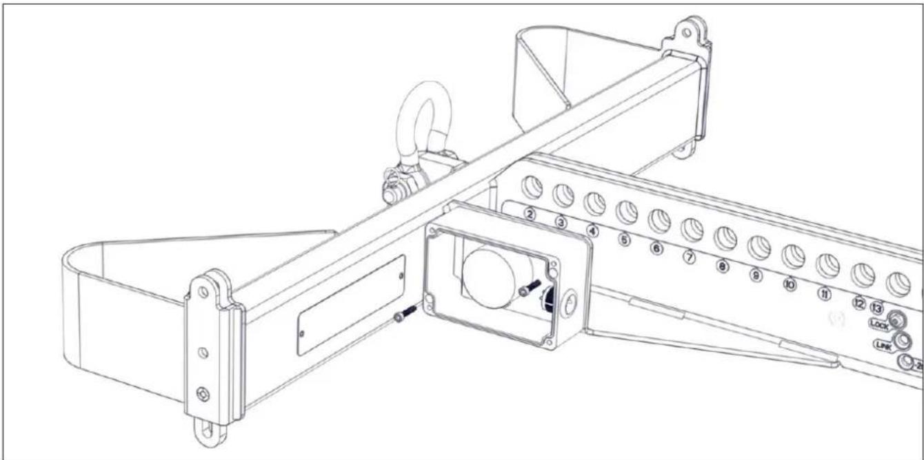
Position the box on the outside of the bracket on the left side of the grid. There are two M4x20mm Cap head screws supplied with the sensor. These go through the holes in the bottom left and top right of the box into the threaded holes in the grid bracket. Tighten using an M3 Allen Key to ensure a tight fit.
natural_image
Technical line drawing of a mechanical assembly with numbered components (no text or symbols)Refit the Lid
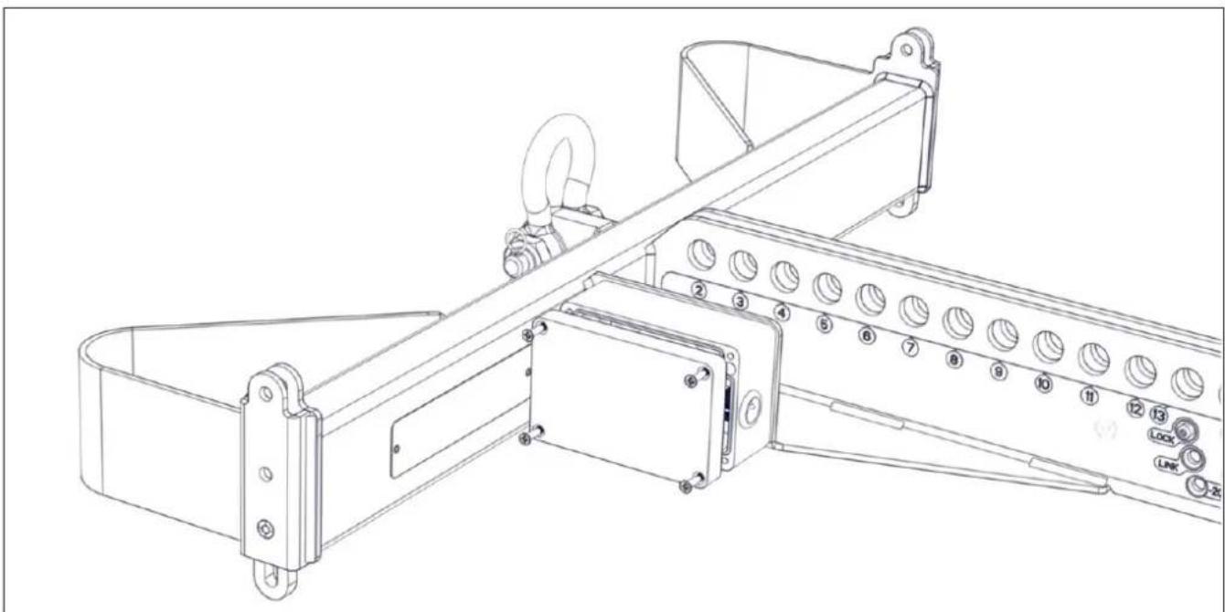
The lid can be re-fitted, check that the gasket on the underside of the lid edge is intact to ensure that the lid is sealed once screwed in position. Note that the design of the box is such that the mounting and lid screws are positioned outside the lid gasket to ensure that there will be no moisture ingress through their holes. All screws are stainless steel to avoid corrosion when used outdoors.
natural_image
Technical line drawing of a mechanical assembly with numbered components (no text or symbols)The Sensor in Position
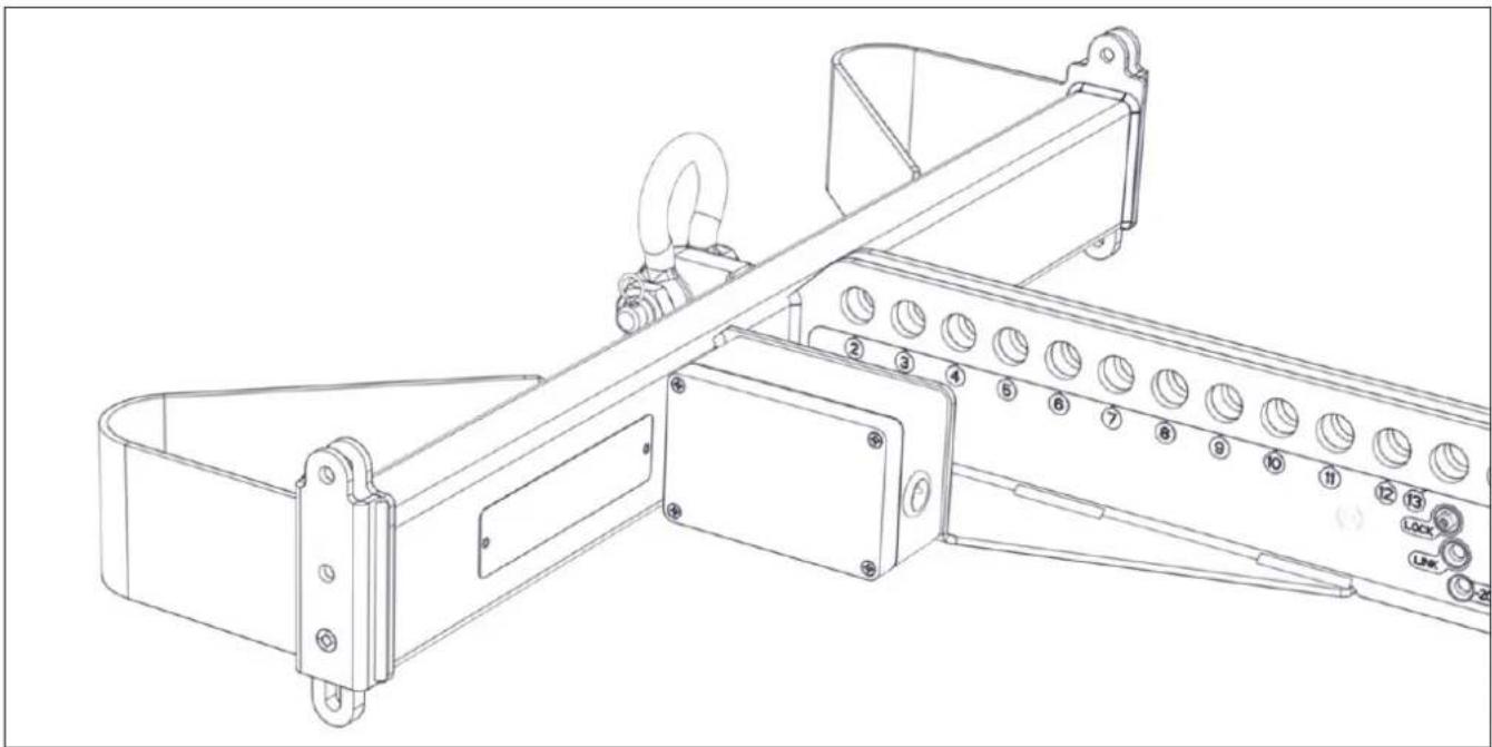
natural_image
Technical line drawing of a mechanical assembly with numbered components (no text or symbols)The Sensor is now ready for use. It is entirely passive so needs no power supply or batteries (the read-out display requires two PP3 batteries). It can be connected to the read-out sensor with a standard 3-pin XLR mic cable of any length.
Martin Audio supply a cable designed specifically for use with the inclinometer system. Part Number PWA00057. This is a 35m cable using high grade AES spec microphone cable fitted with male and female Neutrik NC3XX-HD connectors which are extra rugged and have an IP rating of IP67 to enable use outdoors in all weather conditions.
Note that a single ASM20019 read-out display can be used with any number of sensors, it is not necessary to have the same number of displays as sensors, one display can be plugged into each inclinometer cable, one at a time to take a reading of the angle before entering the figure into the DISPLAY project.
Flown Systems
WPC's rigging has been derived from the highly successful rigging system employed on the MLA Mini Multicellular system. This has proved to be popular, quick and above all safe. Rigging WPC will be instantly familiar to anyone who has rigged Martin Audio systems in the past, we have made a few minor improvements to make it even easier to use and it has proved to be incredibly quick to fly and land.
WPC uses a three-point rigging system. The mechanical load of the array is taken through the side-mounted steel rigging strips which securely connect one cabinet to the next, while the best possible coupling between cabinets is ensured by means of the rear rigging points which allow a range of angle adjustment from 0.5^ to 10^ .
natural_image
Technical diagram of a mechanical assembly with a yellow component and a red arrow pointing to a specific part (no text or symbols present)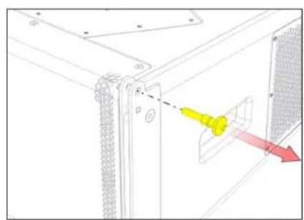
natural_image
Technical diagram of a mechanical assembly with a yellow tool inserted into a housing (no text or symbols visible)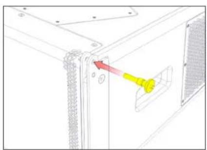
natural_image
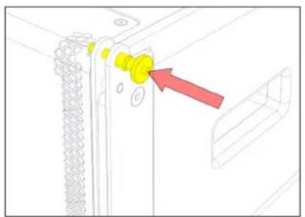
Technical line drawing of a mechanical assembly with a yellow tool inserted into a component (no text or symbols)Fig.1 - push central button Fig.2 - remove rigging pin Fig.3 - replace rigging pin
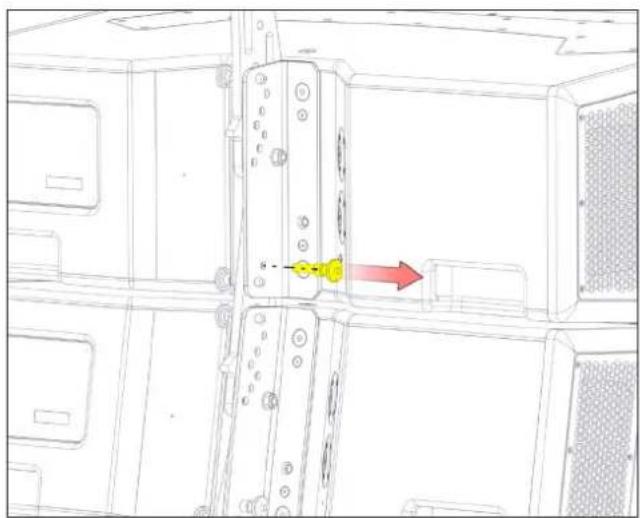
The cabinets are joined using machined quick release Rigging Pins. These have spring loaded ball bearings at the end of the pin which protrude beyond the outer diameter of the pin thus locking them in place. To release them, the central button is depressed (fig. 1) whilst pulling the pin clear using the wide flange (fig. 2). This is best done with the fore and index fingers pulling the pin whilst your thumb depresses the central button, a very quick and easy operation. When using the pins to link cabinets, the central button must again be depressed so the pin can be pushed into position (fig. 3). It is important to check that the central button does not remain depressed once you have put it in place as this would indicate that the pin has not been pushed all the way into position and the ball bearings at the end of the pin have not been able to pop out and lock the pin in place. If the pin is not locked the array is unsafe. The pin MUST be repositioned until it is securely locked in place.
natural_image
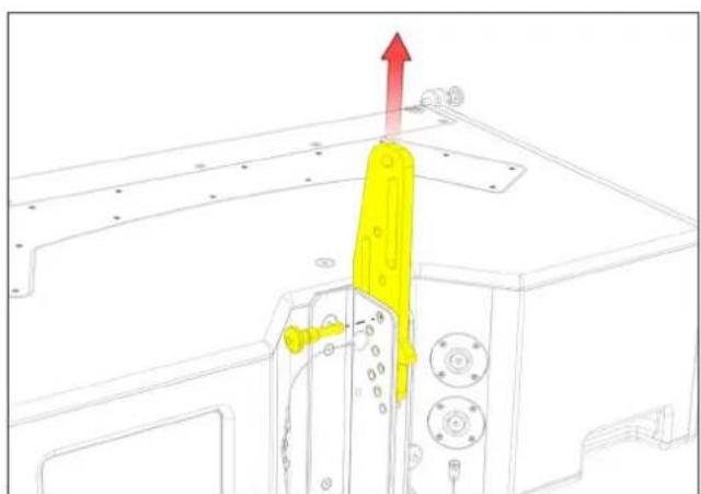
Technical line drawing of a mechanical assembly with a yellow component and red upward arrow (no text or symbols)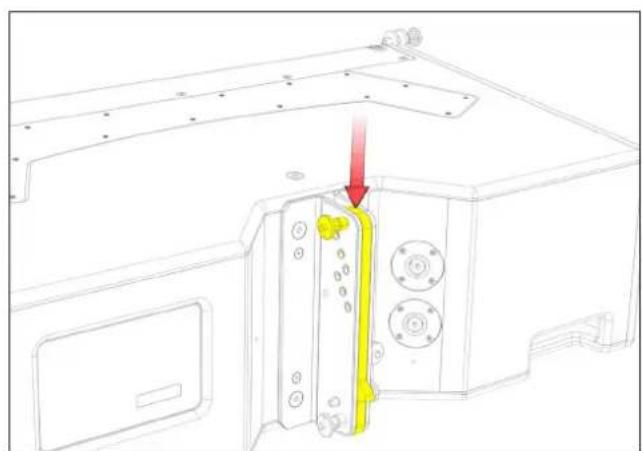
natural_image
Technical line drawing of a microwave oven with a yellow component inserted, showing mounting hardware and a red arrow indicating direction (no text or symbols)Fig 4 - drop link up Fig.5 - drop link down
Inter-cabinet angles are set using the rear rigging assembly. This consists of a sliding drop link bar with indexed holes which can be slid vertically upwards between the two constraining steel brackets, and secured with the Rigging Pins in one of several different positions determined by the holes in the rear bracket assembly, allowing inter-cabinet angle adjustment in six incremental steps of 0.5^ , 1^ , 2^ , 4^ , 6.5^ , and 10^ .
Rigging WPC with the WPCGRIDt Touring Flying Frame
WPC cabinets conveniently truck fully enclosed in a custom designed Transport Dolly, preconfigured in blocks of four, and are rigged straight out of the Transport Dolly to provide an extremely fast and streamlined process.
The cabinets travel in the Transport Dolly at maximum curvature. The Transport Dolly is manufactured around a welded aluminium frame with timber inserts coated in textured paint, and it has nylon skids on the base to support the cabinets and rubber pads on the underside of the top to hold the four cabinets securely when in transit. After removing the top of the Transport Dolly and the supporting poles, the WPC array is easily accessible for rigging. Rigging pins are inserted at the holes required for the cabinet angles as predicted by your DISPLAY 2.3 project, and then the array is lifted so that the angles open until the rear rigging reaches the stops limited by the rigging pins at the preset angles. A second rigging pin is put in place on each cabinet to lock the angles so the array can't collapse back down.
Once the array is flown out of the Transport Dolly, the poles can be placed in the bottom section and the top latched on to the base keeping it compact for storage.

IMPORTANT SAFETY NOTE
The top of the Transport Dolly has the Martin Audio logo milled into it and arrows to indicate that it must only be pushed in the long direction. The Transport Dolly must not be travelled side-on!
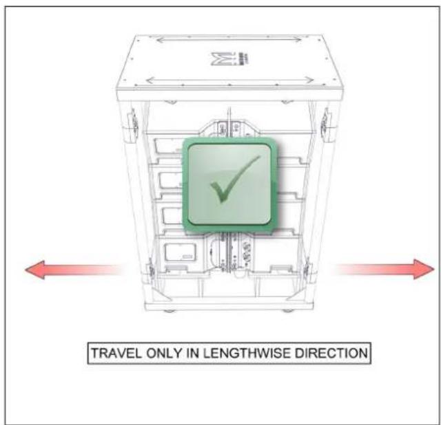
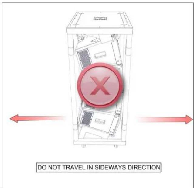
The following example illustrates the procedure for rigging an array of eight WPC cabinets with the WPCGRIDt Touring Flying Frame:
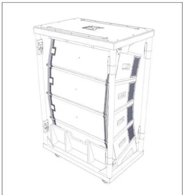
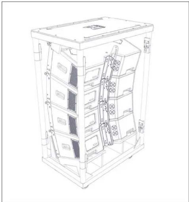
Wheel a WPC Transport Dolly complete with four cabinets into place and position it under the chosen rigging point.
natural_image
Technical line drawing of a multi-level electronic device chassis (no text or symbols)Fig 6 - transport dolly Fig. 7 - transport dolly
natural_image
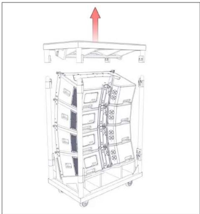
Technical line drawing of a multi-level server rack unit with internal components (no text or labels)Unlatch the top from the supporting poles in four places, lift it off and set it aside.
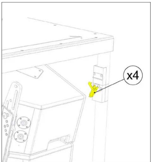
Fig. 8 - unlatch top Fig. 9 - lift off top
natural_image
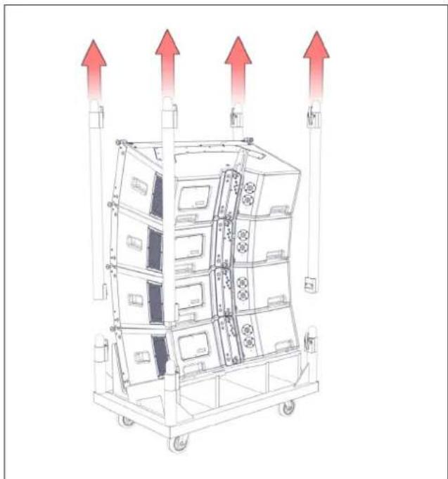
Technical line drawing of a multi-tiered rack-mounted device with a red upward arrow indicating motion (no text or symbols)Unlatch the supporting poles from the Transport Dolly tray and lift them off.
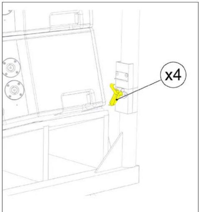
Fig. 10 - unlatch poles Fig. 11 - remove poles
natural_image
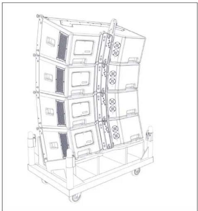
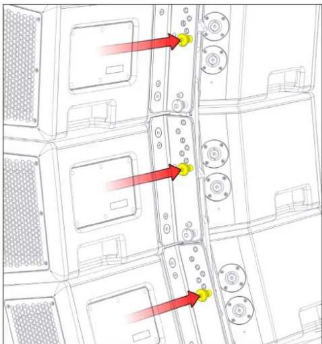
Technical line drawing of a multi-tiered industrial machine with red upward arrows indicating motion or force directions (no text or symbols)With the supporting poles removed from the Transport Dolly the inter-cabinet angles should now be checked or, if not already preselected, set them now according to the predictions from your DISPLAY 2.3 project.
natural_image
Technical line drawing of a multi-tiered industrial storage unit with wheels and control panels (no text or symbols)Fig. 12 - preselect angles Fig. 13 - preselect angles
natural_image
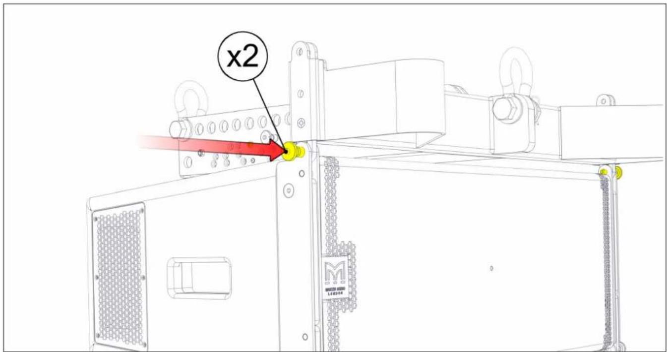
Technical line drawing of a multi-panel server rack with red arrows pointing to specific components (no text or symbols present)Attach the WPCGRIDt Flying Frame to the top cabinet. Insert a rigging pin at the front rigging position on each side of the top cabinet.
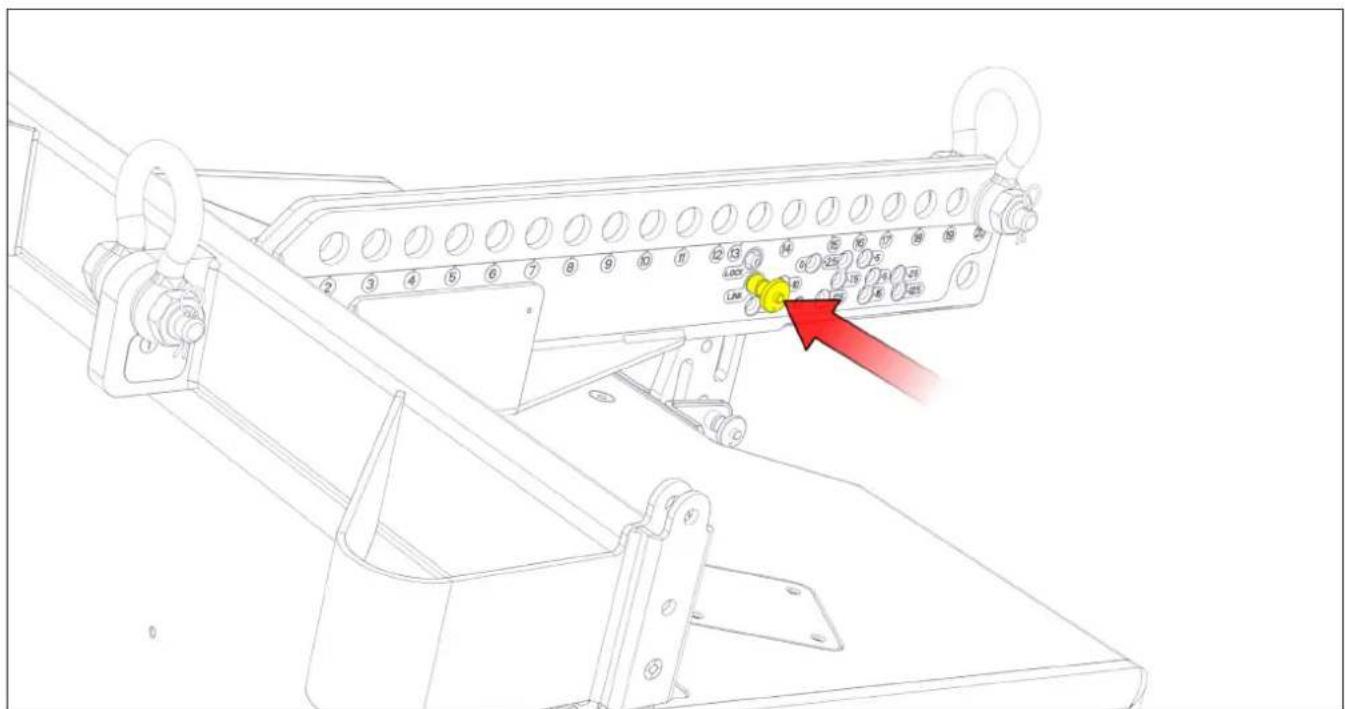
Attach the drop link from the rear of the top cabinet to the Flying Frame at the LINK position.
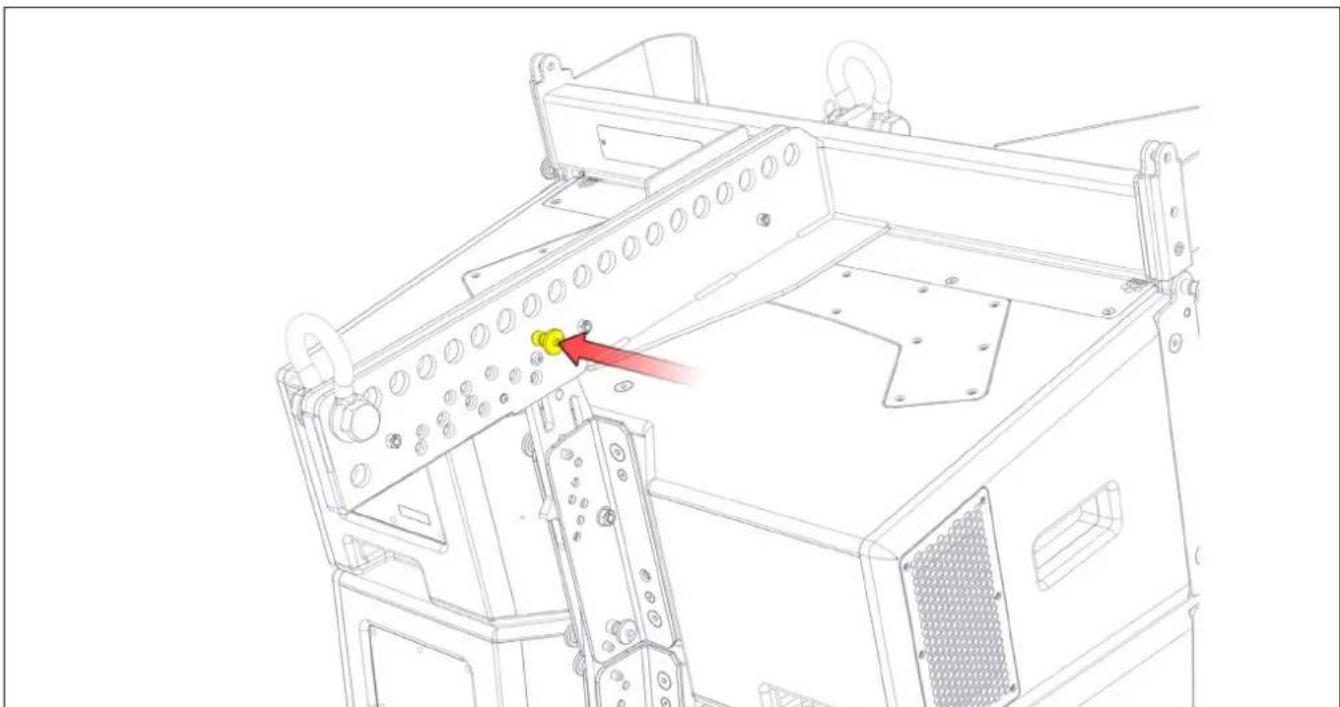
Insert a Rigging Pin at the LOCK position.
natural_image
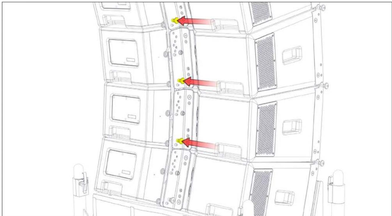
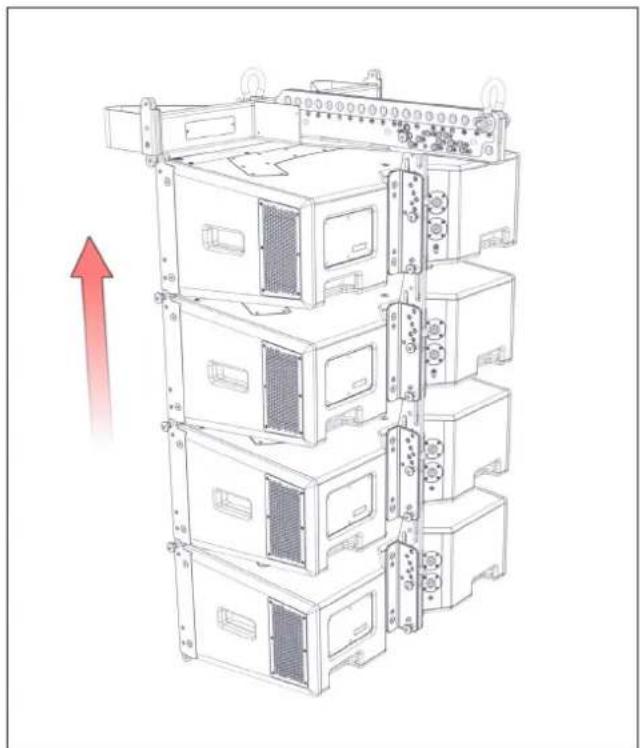
Technical line drawing of a mechanical assembly with a highlighted component (no text or symbols)Lift the array clear of the Transport Dolly to a convenient working height. As the array goes up the cabinets will open up to the angles that you have preselected from the DISPLAY 2.3 project prediction. Insert a further Rigging Pin at the LOCK position on each cabinet to lock the inter-cabinet angles. At this stage the cable loom should be attached to the grid and the first four cabinets connected. As more cabinets are added they should be connected to the loom and link cables between cabinets connected where required. Cables are not shown for clarity.
natural_image
Technical line drawing of a multi-tiered server rack with mounting holes and red arrows indicating directional movement (no text or symbols)Position a second loaded WPC Transport Dolly underneath the array, remove the top and poles, and prepare the cabinets to be added to the array.
natural_image
Technical line drawing of a multi-tiered server rack unit with mounting hardware and a red upward arrow indicating motion (no text or symbols)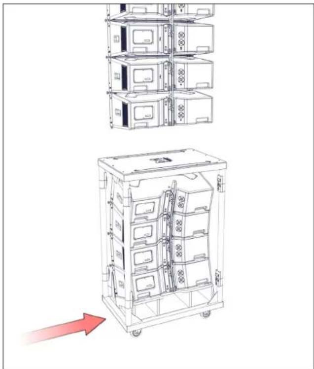
natural_image
Technical line drawing of a multi-level rack-mounted device with a red arrow indicating motion (no text or symbols)Fig. 14 - lift array Fig. 15 - position second block
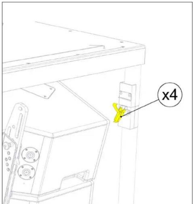
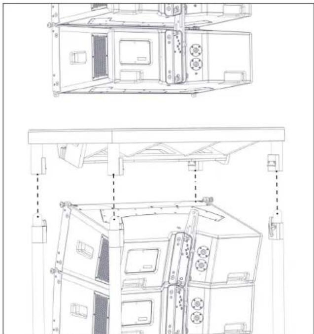
Unlatch the top from the supporting poles in four places, lift it off and set it aside.
natural_image
Technical line drawing of a mechanical device with multiple views and mounting brackets (no text or symbols)Fig. 16 - unlatch top Fig. 17 - lift off top
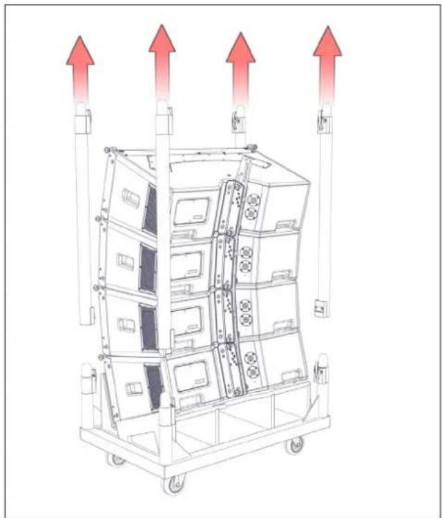
Unlatch the supporting poles from the Transport Dolly tray and lift them off.
natural_image
Diagram of a multi-tiered industrial machine with red upward arrows indicating flow or movement (no text or symbols present)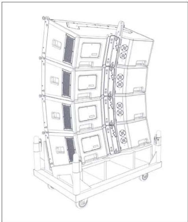
natural_image
Technical line drawing of a multi-tiered industrial machine chassis with wheels and control panels (no text or symbols)Fig. 18 - remove poles Fig. 19 - remove poles
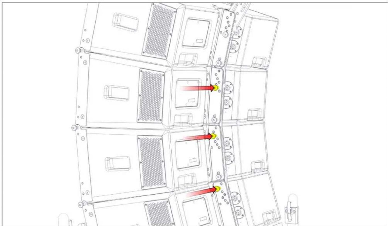
Preselect the inter-cabinet angles on the lower three cabinets according to the predictions from your DISPLAY 2.3 project.
natural_image
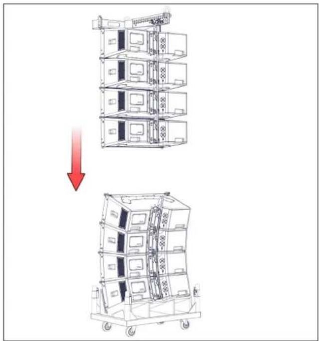
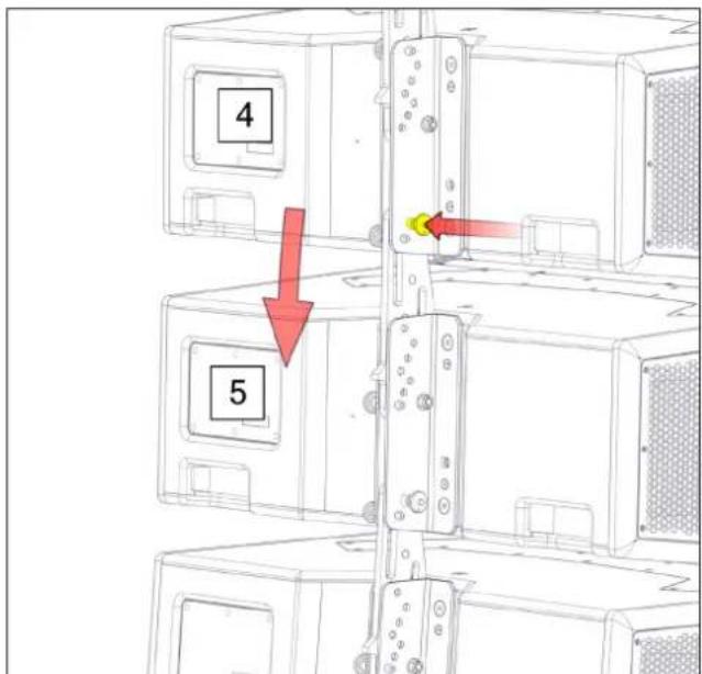
Technical line drawing of server rack with multiple units and highlighted ports (no text or symbols)Lower the array and engage the front rigging points of the fourth cabinet with the front rigging points of the fifth cabinet. Insert a Rigging Pin on both sides.
natural_image
Diagram showing a multi-tiered storage unit being lifted by a red arrow, with no visible text or symbols.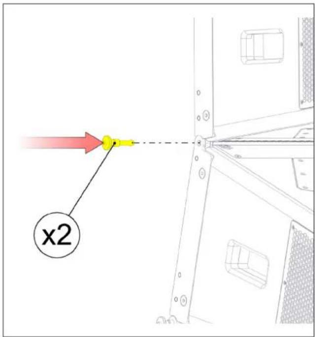
Fig. 20 - lower array Fig. 21 - attach second block
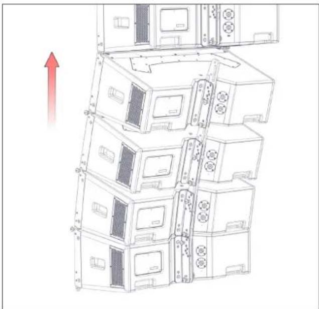
Raise the array clear of the Transport Dolly, allowing access to the rear of the array. The cabinet angles will open as far as the pins will allow to the angle that has been pre-selected. Insert Rigging Pins at the LOCK position on the remaining cabinets.
natural_image
Technical line drawing of a multi-tiered server rack unit with mounting holes and ventilation slots, showing no text or symbols.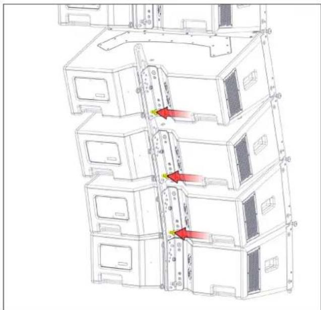
Fig. 22 - lift array Fig. 23 - insert lock pins
Swing the bottom four cabinets (which will now be a rigid array due to the locking pins) backwards until butted against the upper half of the array. Insert a pin in the rear rigging bracket at the correct angle. Allow the bottom four cabinets to swing back down and insert a Rigging Pin at the LOCK position on the fourth cabinet. Connect the cable loom and any link cables as required to the lower four cabinets.
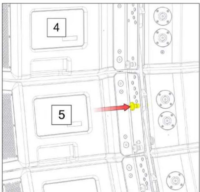
Fig. 24 - insert rigging pin Fig. 25 - insert lock pin
Raise the array to the final trim height. The use of either one or two motors allows both negative (down-tilt) or positive (up-tilt) array angles to be easily achieved.
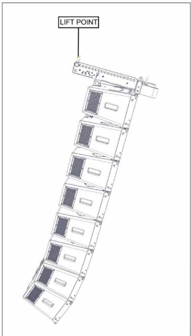
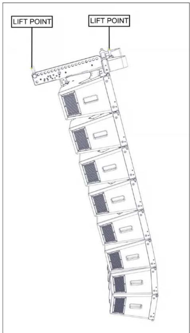
Fig. 26 - negative array tilt Fig. 27 - positive array tilt
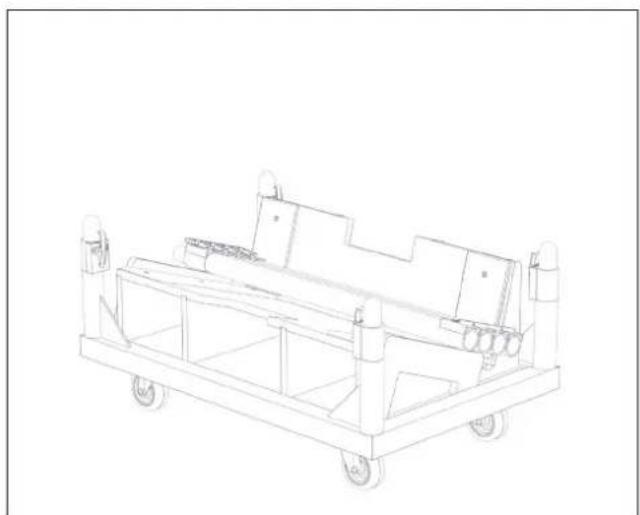
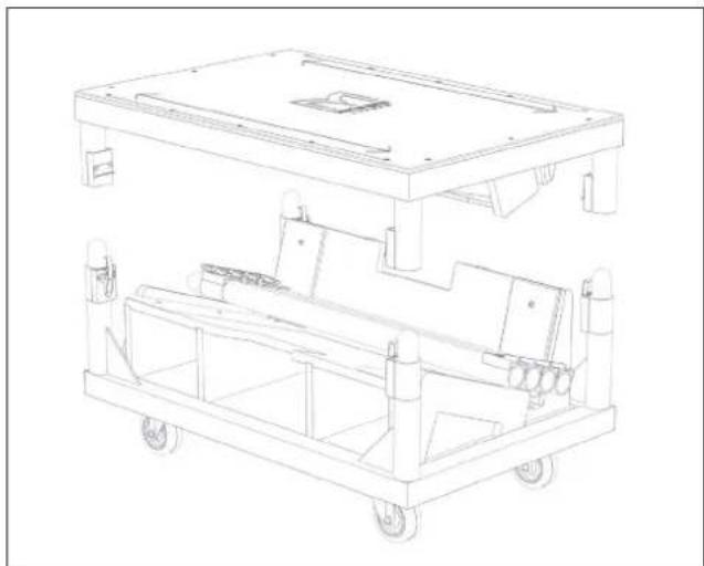
Stow the supporting poles in the tray of the Transport Dolly and replace the top.
natural_image
Line drawing of a mechanical cart with wheels and control panels (no text or symbols)Fig. 28 - stow poles Fig. 29 - replace top
natural_image
Technical line drawing of a two-tiered industrial cart with wheels and internal compartments (no text or symbols)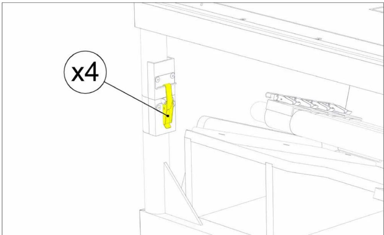
Landing the Array
Landing an array is simply a reversal of the rigging procedure outlined above, lowering the array and guiding the bottom four cabinets into a WPC Transport Dolly, unpinning the lower block of four, and repeating with the top four cabinets.
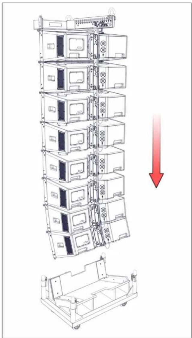
Lower the array to a convenient working height. Disconnect the speaker cables. Position a WPC Transport Dolly underneath the array, and remove the top and supporting poles.
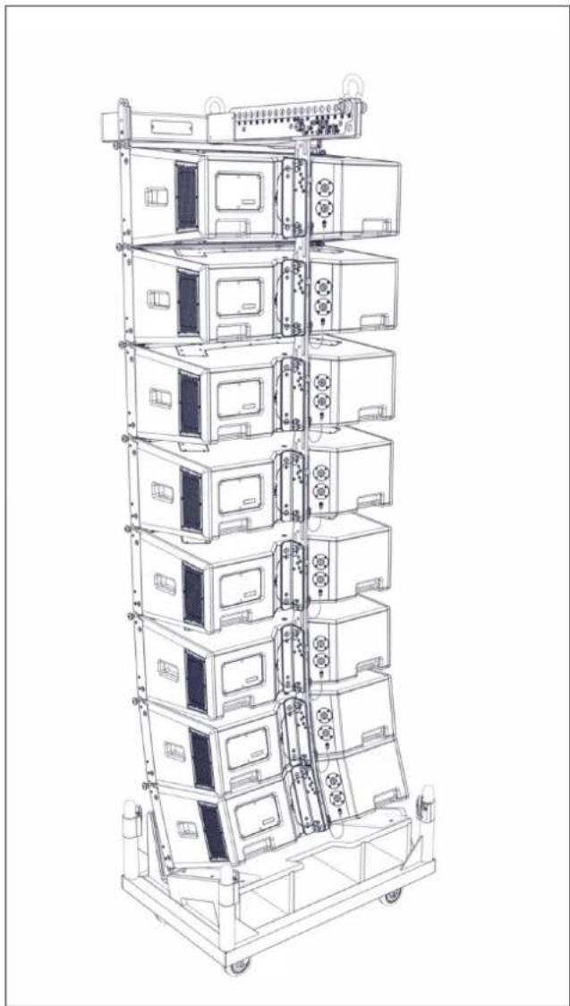
Lower the array further, and guide it into the Transport Dolly until the bottom cabinet is seated fully in the tray. Remove the LOCK pins from the bottom four cabinets, allowing the cabinets to collapse down until the trapezoidal sides are touching.
natural_image
Technical line drawing of a multi-tiered vertical rack-mounted device with a red downward arrow indicating compression or disassembly (no text or symbols present)Fig. 30 - lower array Fig. 31 - lower array
natural_image
Technical line drawing of a multi-tiered vertical rack-mounted device with multiple compartments and control panels (no text or symbols visible)Unpin the fifth cabinet from the fourth cabinet at the rear, first removing the LOCK pin and then removing the LINK pin.
natural_image
Technical line drawing of a mechanical assembly with no visible text or symbols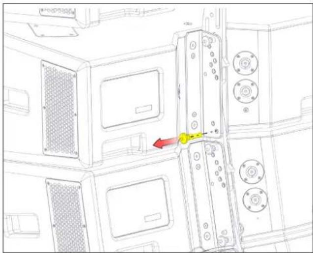
natural_image
Technical line drawing of a microwave oven with labeled components and a red arrow indicating a specific part (no text or symbols present)Fig. 32 - remove LOCK pin Fig. 33 - remove LINK pin
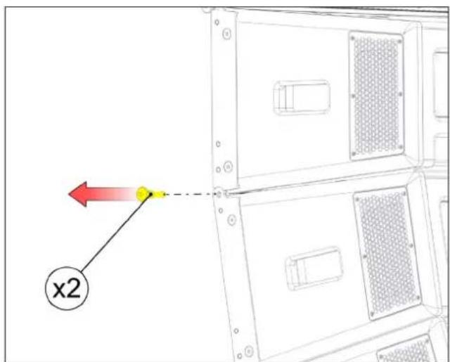
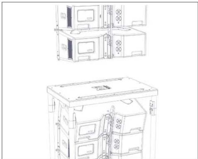
Remove the Rigging Pins from the front of the fifth cabinet at each side. The top four cabinets can now be lifted clear of the Transport Dolly. Replace the supporting poles and top, wheel the Transport Dolly away and prepare for transport.
natural_image
Technical line drawings of a multi-compartment electronic device with internal components and mounting brackets (no text or symbols)Fig. 34 - remove rigging pin Fig. 35 - replace poles and top
Lower the remaining four cabinets and, repeating the procedure above, lower the array into a Transport Dolly.
Rigging WPC with the WPCGRIDi Install Flying Frame
WPC cabinets are normally flown one at a time to form an array in a permanent installation, joining cabinets first at the front rigging points and then at the rear, selecting each inter-cabinet angle according to your DISPLAY 2.3 project prediction.
An array of up to a maximum of eight WPC cabinets can be flown in this way.
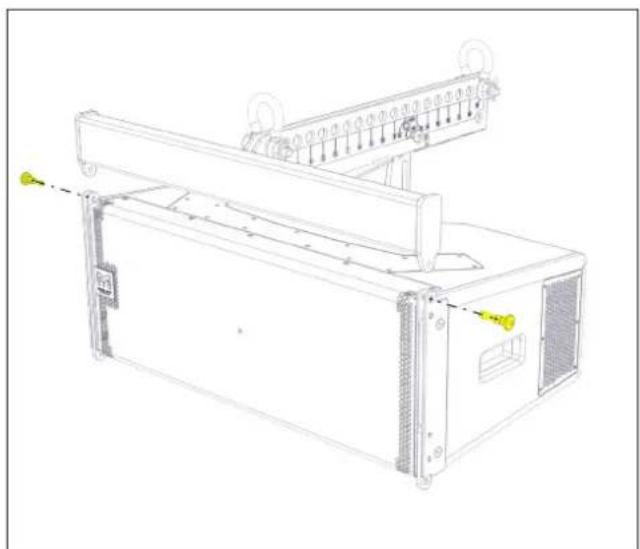
Attach shackles to the front and rear lift points of the Flying Frame. If using only one pickup point attach a shackle to the pickup hole predicted by the DISPLAY 2.3 project. Offer the Flying Frame up to the first box and attach it to the front rigging points by inserting a Rigging Pin at each side.
natural_image
Technical line drawing of a server rack unit with mounting bracket and control panel (no text or symbols)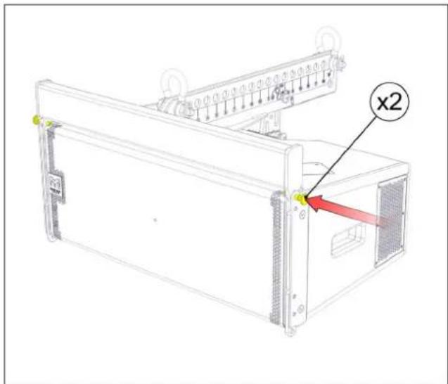
Fig. 36 - attach flying frame Fig. 37 - secure flying frame
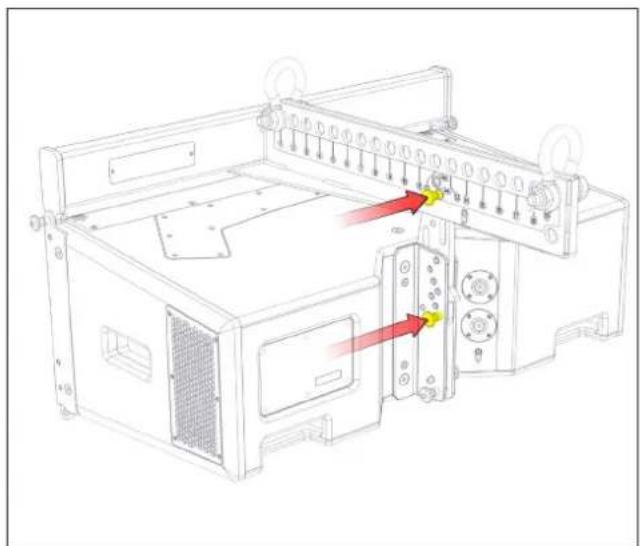
Attach the cabinet drop link to the Flying Frame at the LINK position. Insert a Rigging Pin at the LOCK position on the Flying Frame.
natural_image
Technical line drawing of a mechanical device with red arrows indicating assembly or force directions (no text or symbols present)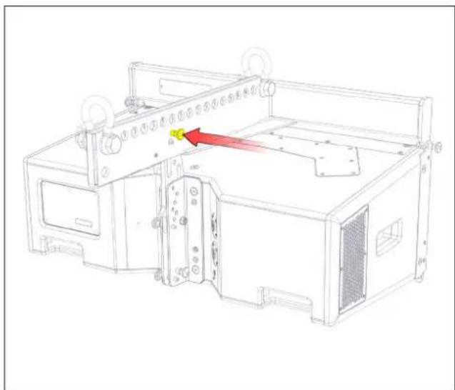
natural_image
Technical line drawing of a mechanical device with no visible text or symbolsFig. 38 - attach flying frame Fig. 39 - secure flying frame
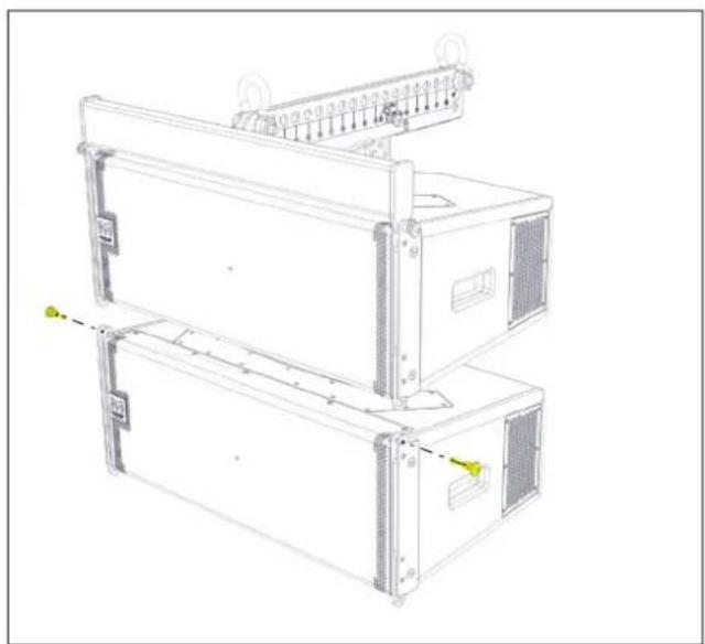
Raise the array and position a second cabinet underneath the first. Attach the front rigging points, inserting a Rigging Pin at each side.
natural_image
Technical line drawing of a server rack unit with mounting brackets and ventilation slots (no text or symbols)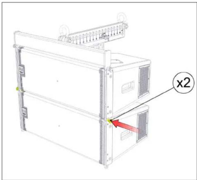
Fig. 40 - attach second cabinet Fig. 41 - secure second cabinet
Slide the first cabinet's drop link upwards and secure it on the second cabinet at the angle position predicted by the DISPLAY 2.3 project. Secure with a Rigging Pin. Insert a Rigging Pin at the first cabinet's LOCK position.

natural_image
Technical line drawing of a multi-tiered server or equipment unit with labeled ports and connectors (no text or symbols present)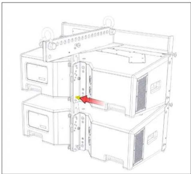
natural_image
Technical line drawing of a multi-chamber industrial machine or control unit with no visible text or symbolsFig. 42 - attach second cabinet Fig. 43 - secure second cabinet
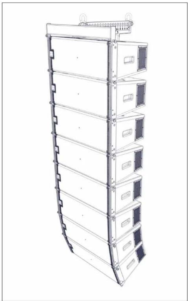
Continue adding cabinets to the array up to a maximum of eight cabinets, ensuring that the inter-cabinet angles are set correctly according to the DISPLAY 2.3 project prediction. Connect speaker cables to the cabinets as each one is added to the array.
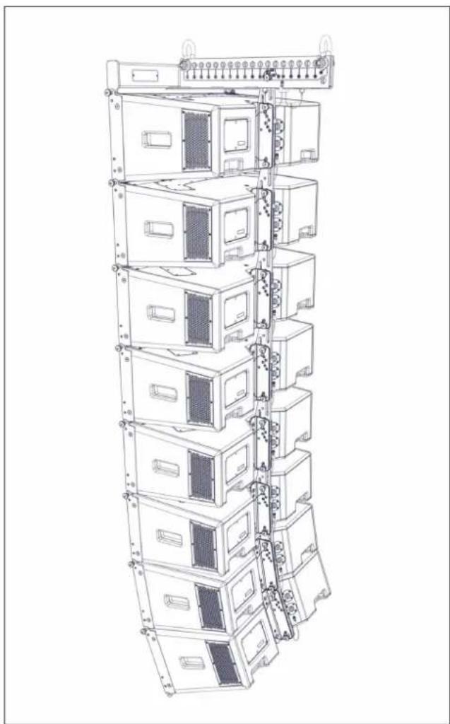
Raise the array to the final trim height.
natural_image
Technical line drawing of a multi-tiered server rack unit (no text or symbols)Fig. 44 - complete array Fig. 45 - complete array
natural_image
Technical line drawing of a multi-tiered server rack unit (no text or symbols visible)The use of either one or two motors allows both negative (down-tilt) or positive (up-tilt) array angles to be easily achieved.
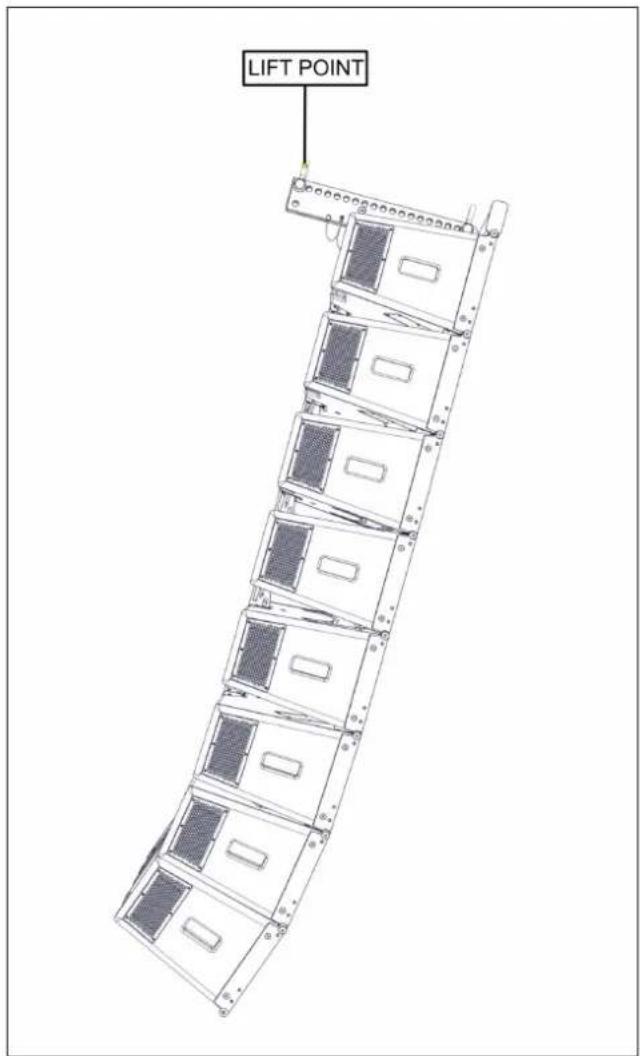
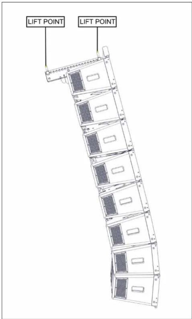
Fig. 46 - negative array tilt Fig. 47 - positive array tilt
Ground Stacking WPC - Upward Tilt
Ground stacks of WPC cabinets are assembled using the Touring Flying Frame. The front stabiliser bars provide a wide and stable platform for assembling an array of up to six WPC cabinets. Ground stacks can be assembled with either a positive or negative array inclination relative to the ground simply by alternate positioning of the Ground Stack Bar. This example is shown with positive (up-tilt) array inclination.
Place the Touring Flying Frame at the desired location. Position the first cabinet on top of the bar, aligning the lower front rigging points with the rigging points on the bar. Secure with Rigging Pins on both sides. Attach the Ground Stack Bar at the -17.5° position on the Touring Flying Frame and secure with a Rigging Pin. Secure the Ground Stack Bar to the first cabinet with a Rigging Pin at the LINK position.
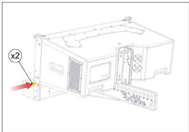
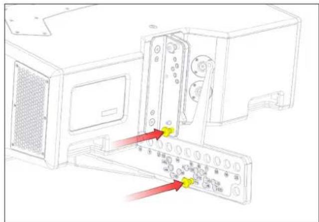
Fig. 48 - engage front rigging points Fig. 49 - insert rigging pins
Position the second cabinet on top of the first, aligning its front rigging points with the cabinet below, and secure with Rigging Pins on both sides. Slide the drop link upwards and set the inter-cabinet angle according to the DISPLAY 2.3 project prediction.
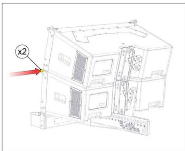
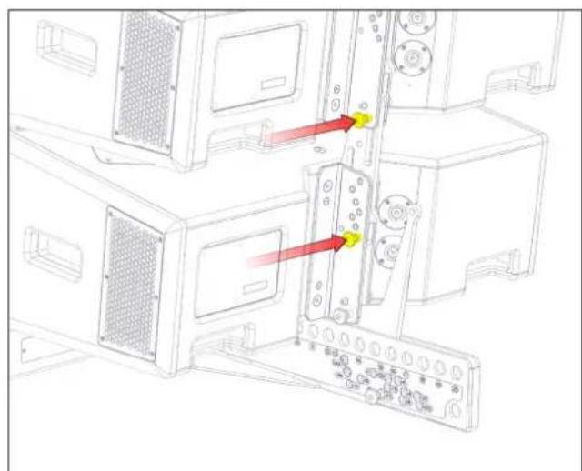
natural_image
Technical line drawing of a computer tower with two panels and red arrows indicating connection points (no text or symbols)Fig. 50 - attach second cabinet Fig. 51 - insert rigging pins
Continue to add further cabinets one at a time to the ground stack, securing the front rigging points with Rigging Pins and setting the inter-cabinet angles as you go along, until the ground stack is complete.
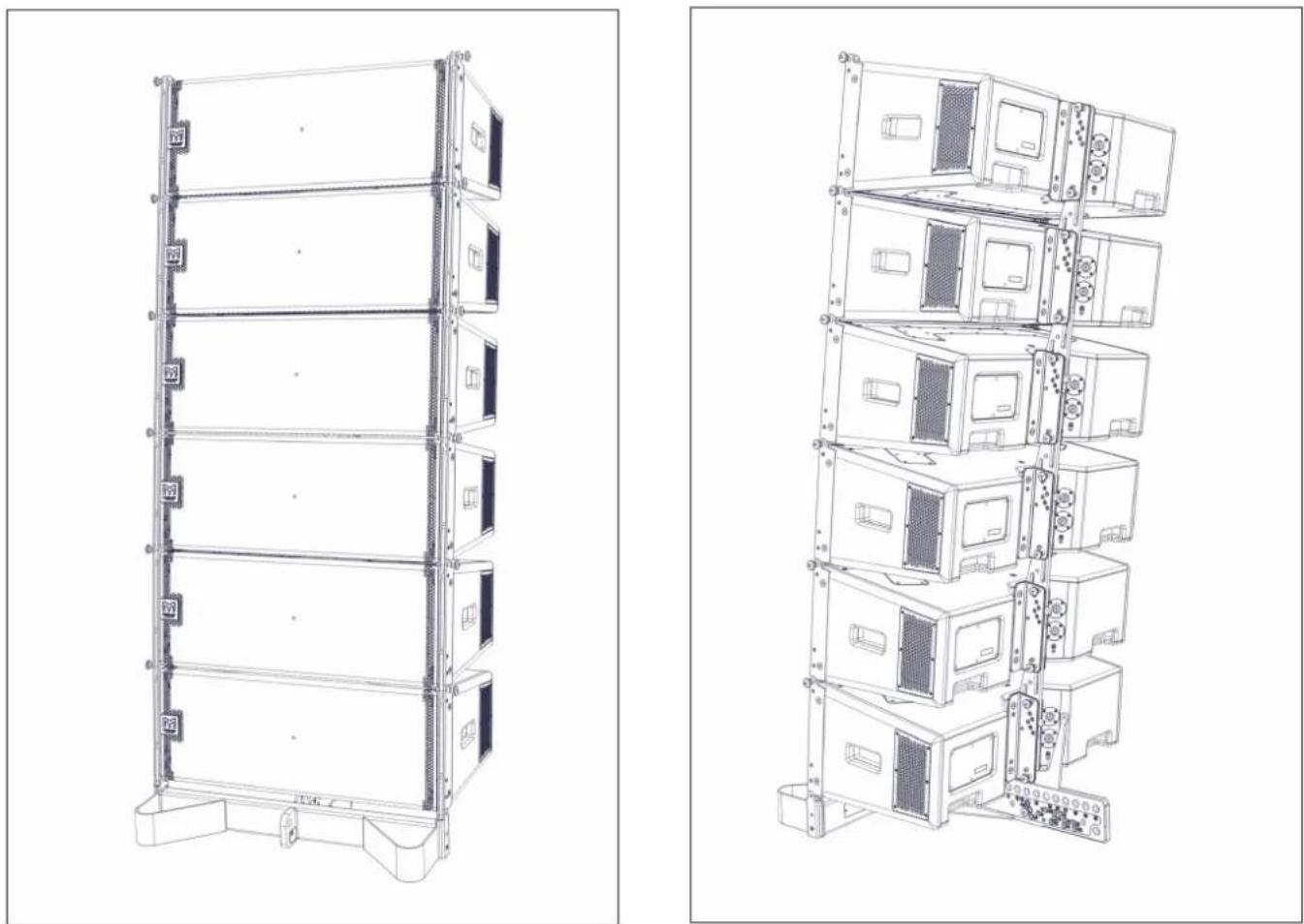
natural_image
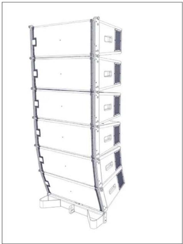
Technical line drawings of server rack units, showing front and side views (no text or symbols)Fig. 52 - complete ground stack Fig. 53 - complete ground stack
Ground Stacking WPC - Downward Tilt
This ground stack example is shown with negative (down-tilt) array inclination.
Place the Touring Flying Frame at the desired location. Position the first cabinet on top of the bar, aligning the lower front rigging points with the rigging points on the bar. Secure with Rigging Pins on both sides. Attach the Ground Stack Bar at the -17.5° position on the Touring Flying Frame and secure with a Rigging Pin. Secure the Ground Stack Bar to the first cabinet with a Rigging Pin at the LINK position.
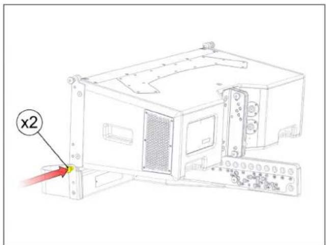
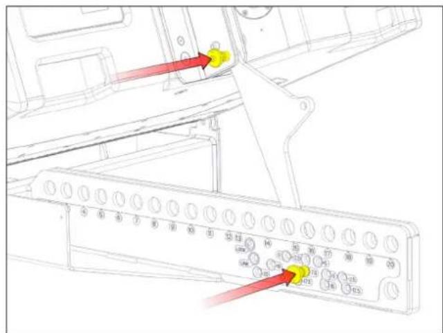
Fig. 54 - engage front rigging points Fig. 55 - insert rigging pins
Position the second cabinet on top of the first, aligning its front rigging points with the cabinet below, and secure with Rigging Pins on both sides. Slide the drop link upwards and set the inter-cabinet angle according to the DISPLAY 2.3 project prediction.
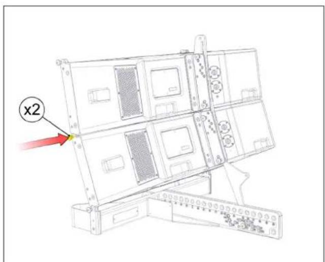
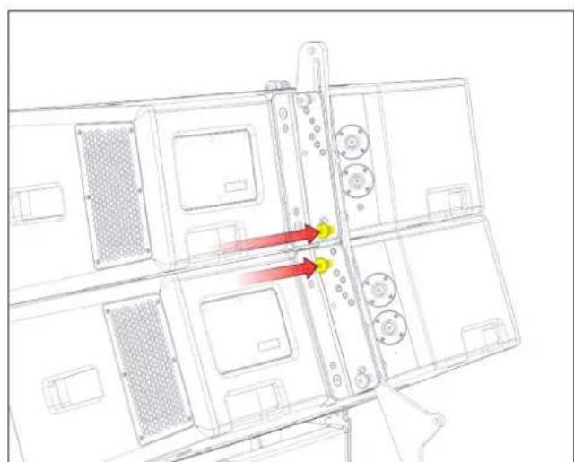
natural_image
Technical line drawing of a multi-chamber electronic device with red arrows indicating directional flow or movement (no text or symbols)Fig. 56 - attach second cabinet Fig. 57 - insert rigging pins
Continue to add further cabinets one at a time to the ground stack, securing the front rigging points with Rigging Pins and setting the inter-cabinet angles as you go along, until the ground stack is complete.
natural_image
Technical line drawing of a multi-tiered storage or rack unit (no text or symbols)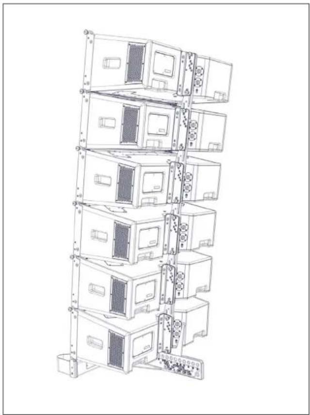
natural_image
Line drawing of a multi-tiered rack-mounted server or rack unit structure (no text or symbols visible)Fig. 58 - complete array Fig. 59 - complete array
Essential Maintenance
WPC - Removing the HF/MF Driver Assembly
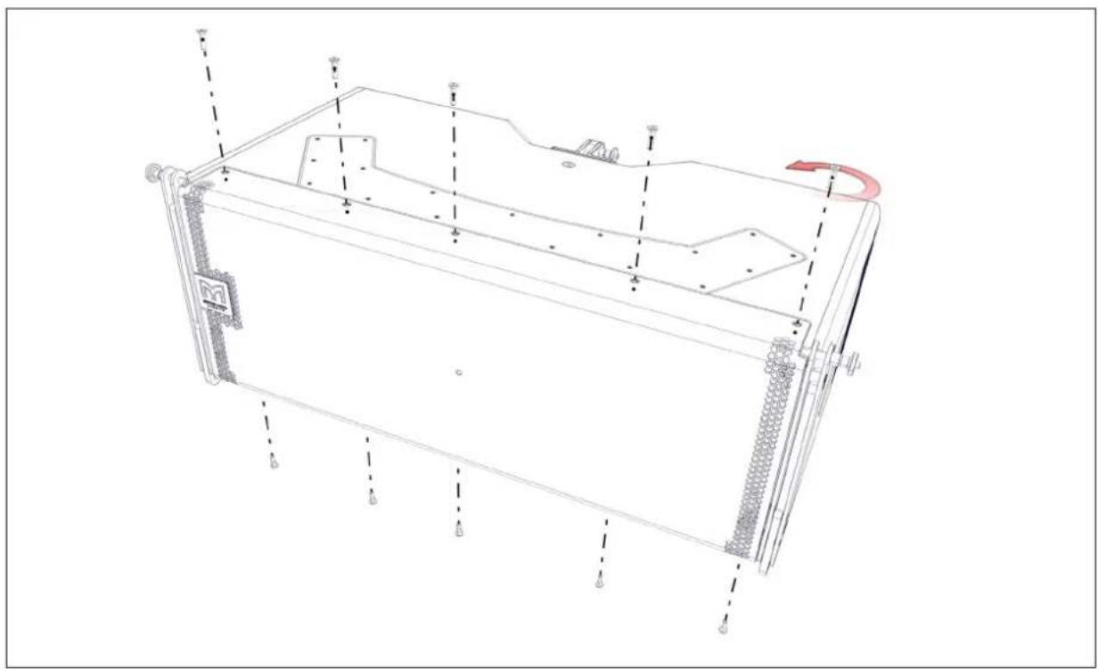
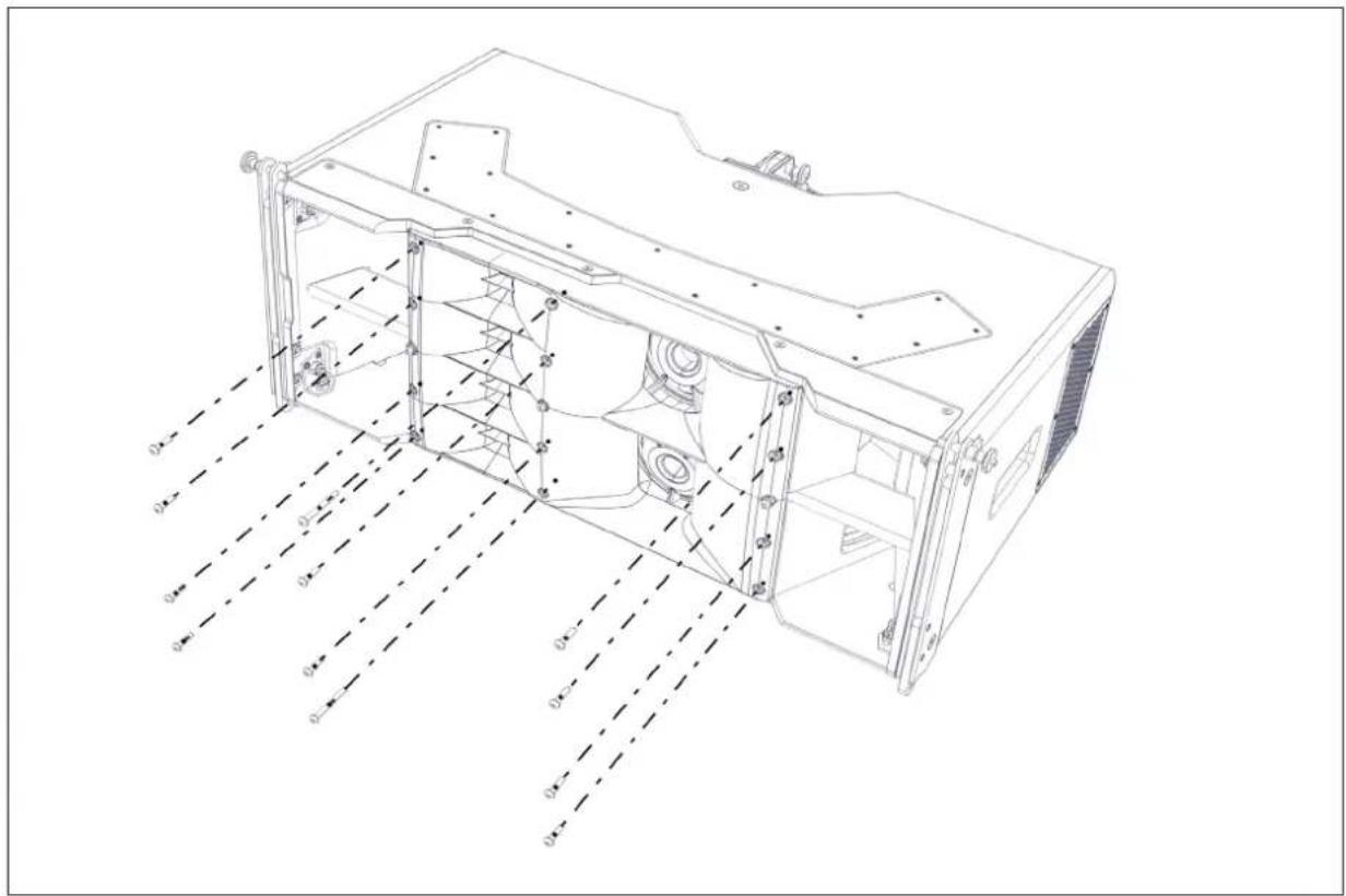
To access the HF and MF drive units first unscrew the ten M5 x 20mm countersunk screws securing the loudspeaker grille.
natural_image
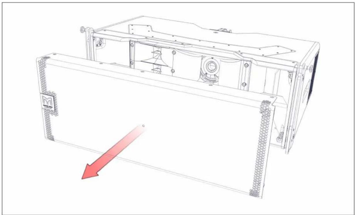
Technical line drawing of a mechanical housing or enclosure with mounting brackets and internal components (no text or symbols)Remove the grille and set it aside.
natural_image
Technical line drawing of a mechanical device with internal components and a red arrow indicating motion (no text or symbols)Next remove the eight M5 x 20mm screws and two M5 x 45mm screws holding the HF/MF horn assembly in place.
natural_image
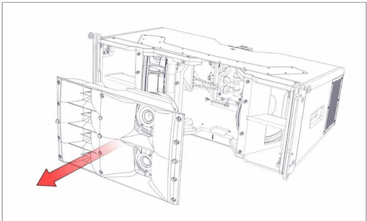
Technical line drawing of a computer case with internal components and dimension lines (no text or symbols)Now remove the complete HF/MF horn assembly from the cabinet. The HF and MF drivers are serviced only as a complete assembly. Please refer to Martin Audio service departments for replacement or servicing.
natural_image
Technical line drawing of a mechanical assembly with internal components and a red arrow indicating direction (no text or symbols present)WPC - Removing a LF Driver
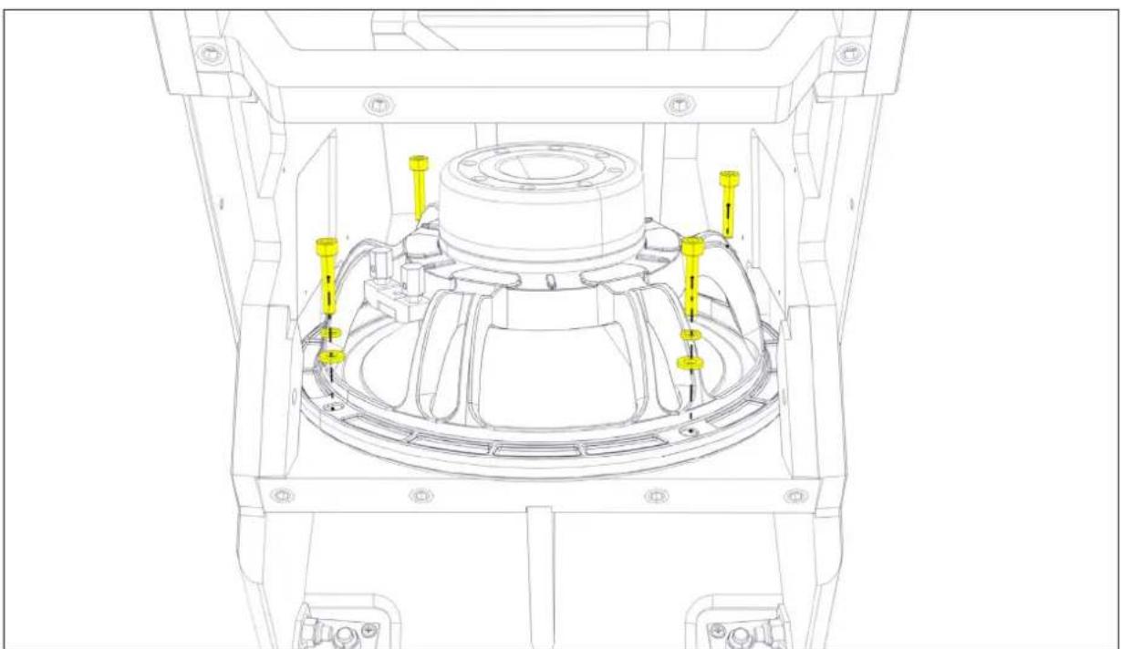
Once the HF/MF horn assembly is removed the LF drive units can be accessed from inside the cabinet, and are secured using screws through the rear of the chassis. Remove the four M6 x 30 cap head screws, flat washers, and spring washers securing the LF drive unit.
natural_image
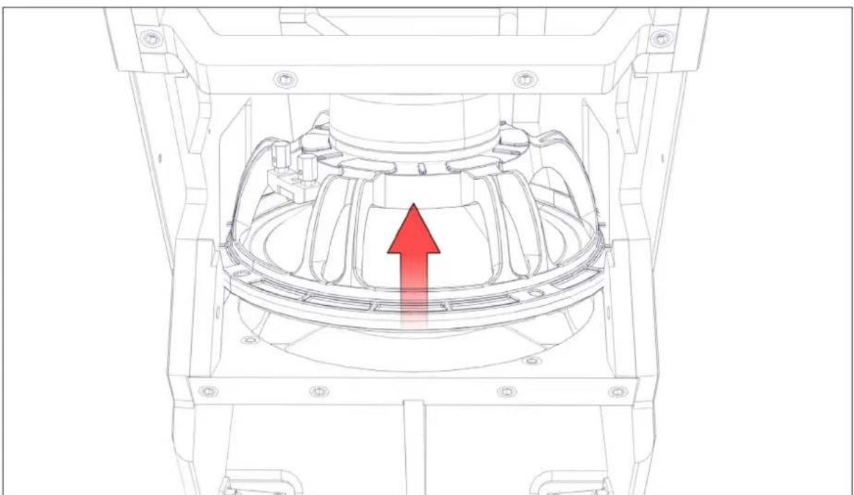
Technical line drawing of a mechanical assembly with yellow connectors and mounting holes (no text or symbols)Disconnect the LF drive unit cables, making a note of their polarity for later reconnection. The LF drive unit may now be lifted carefully out and away from the cabinet for repair or replacement.
natural_image
Technical line drawing of a mechanical component with a red upward arrow indicating a specific feature (no text or symbols present)SX118 Subwoofer - Replacing the Drive Unit
The front grille locates into slots on the top and bottom of the cabinet. Remove it by inserting a flat blade screwdriver into slots in the grille edge and carefully levering it out of the slot.
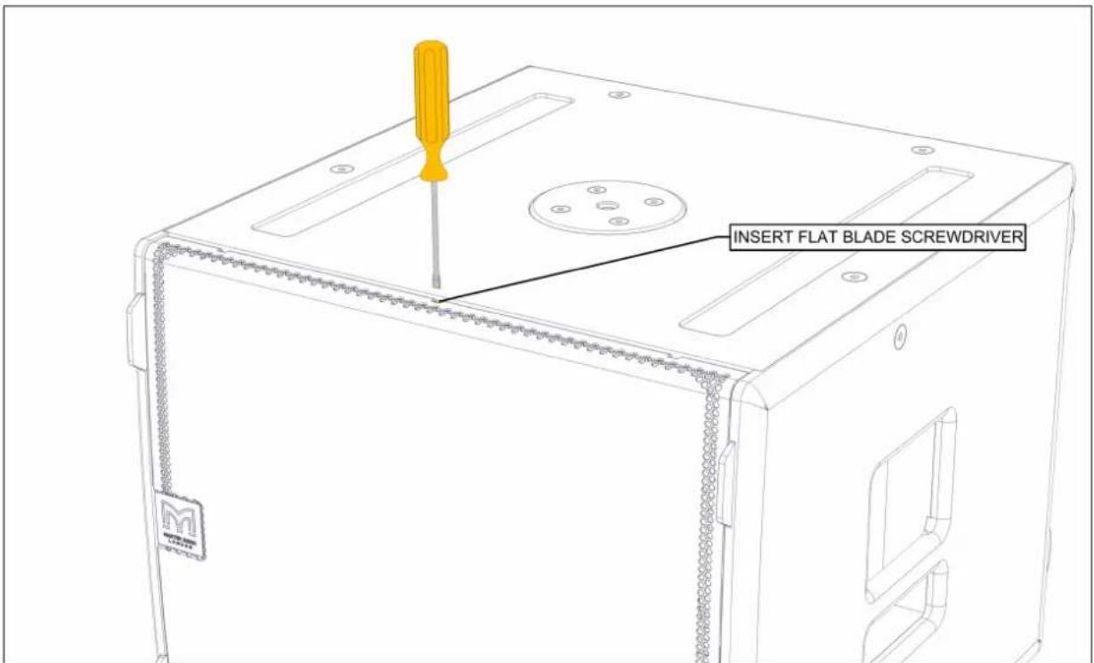
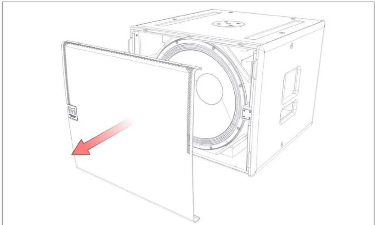
Remove the grill and set it aside.
natural_image
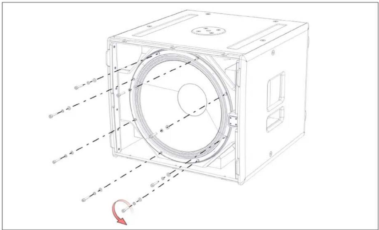
Technical line drawing of a mechanical device with a red arrow indicating a directional change or movement (no text or symbols present)Unscrew the eight M6 x 30mm bolts securing the drive unit. Carefully lift the drive unit out of the cabinet and disconnect the speaker cables, making note of the polarity for later reconnection.
natural_image
Technical line drawing of a mechanical device with internal components and alignment indicators (no text or symbols)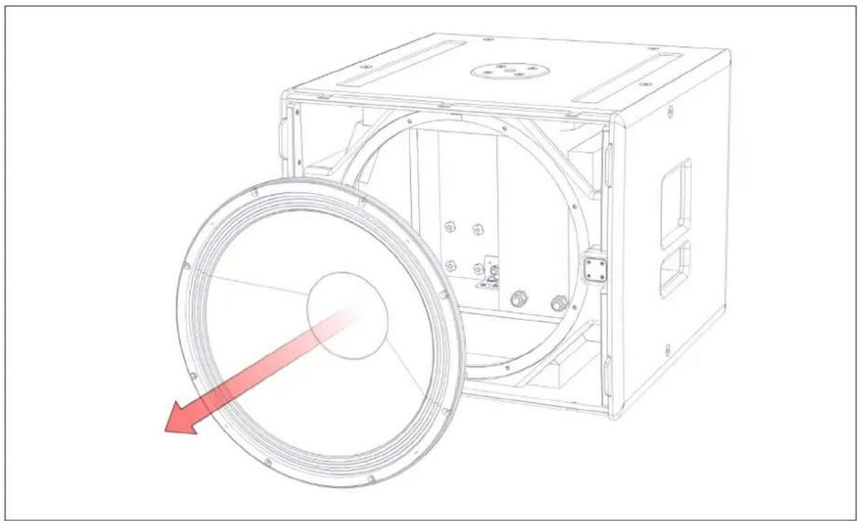
natural_image
Technical line drawing of a mechanical device with a red arrow indicating rotation or force direction (no text or symbols present)SX218 - Replacing a Drive Unit
The front grille locates into slots on the top and bottom of the cabinet. Remove it by inserting a flat blade screwdriver into slots in the grille edge and carefully levering it out of the slot.
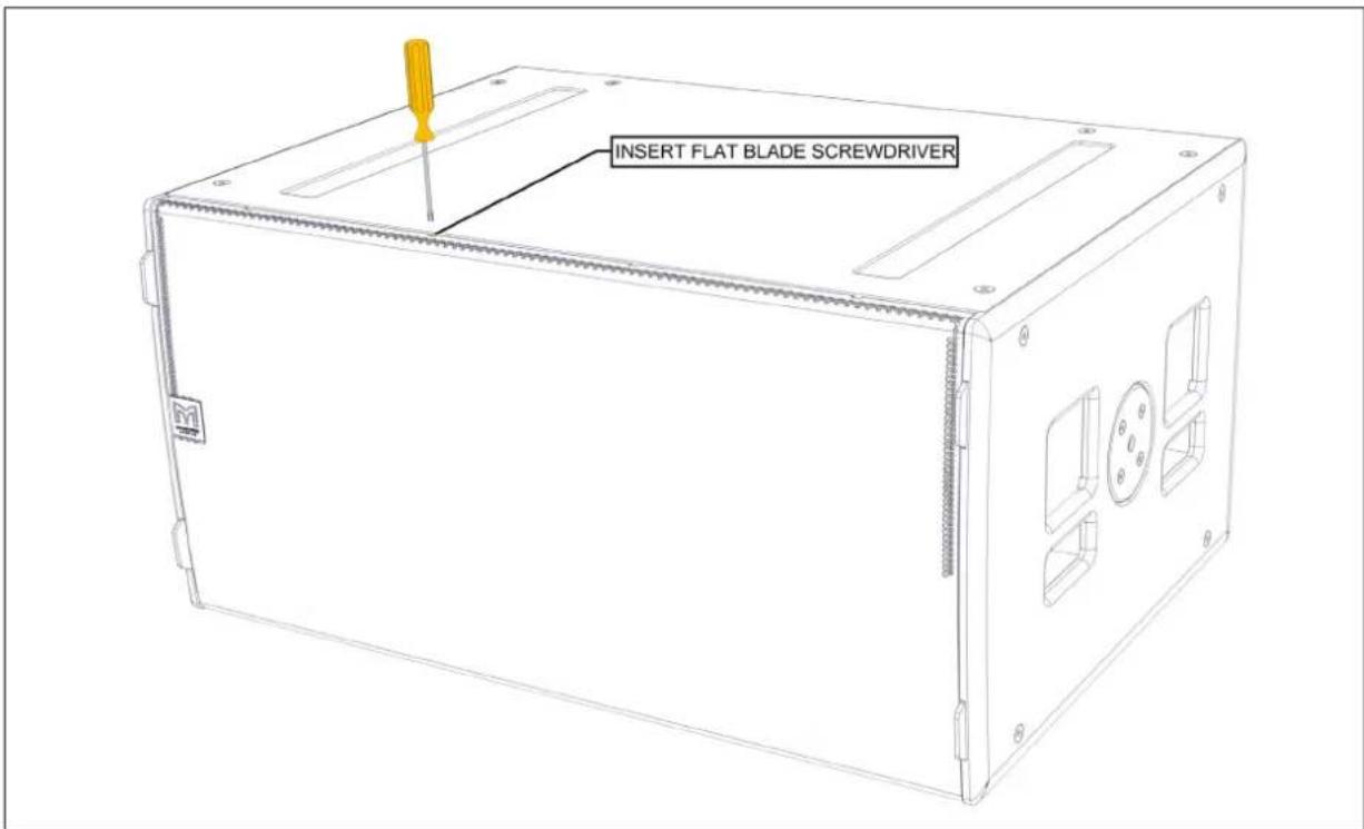
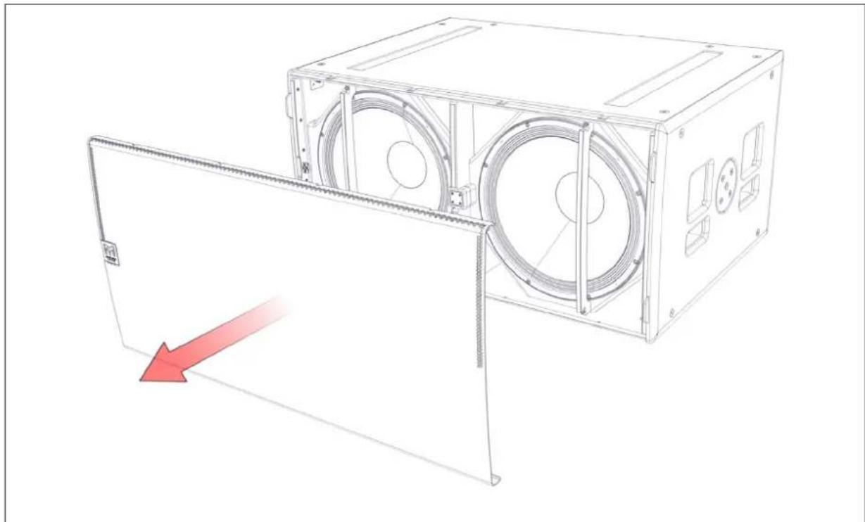
Remove the grille and set it aside.
natural_image
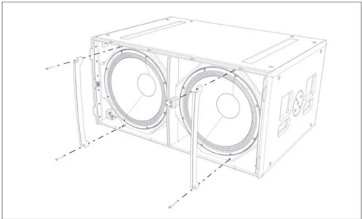
Technical line drawing of a mechanical device with a red arrow indicating a directional change or motion (no text or symbols present)Next unscrew the brace retaining screws and remove the grille braces.
natural_image
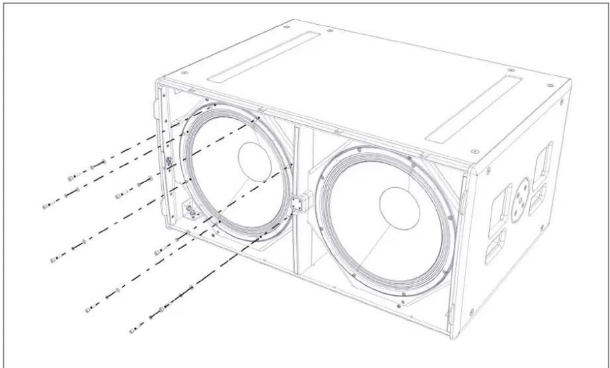
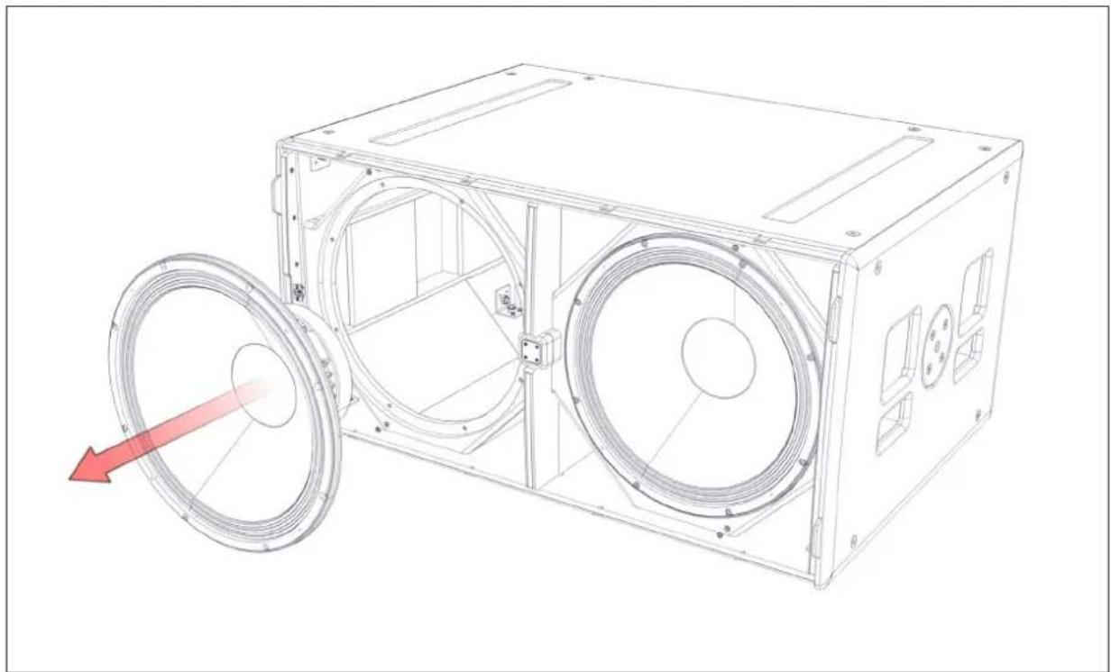
Technical line drawing of a mechanical device with two circular components and mounting brackets (no text or symbols)Unscrew the eight M6 x 30mm bolts securing the drive unit.
natural_image
Technical line drawing of a mechanical enclosure with two circular fans and internal components, showing alignment lines without any text or symbols.Carefully lift the drive unit out of the cabinet and disconnect the speaker cables, making note of the polarity for later reconnection.
natural_image
Technical line drawing of a mechanical housing with two circular components and a red arrow indicating motion (no text or symbols)Specifications: WPC
TYPE Three-way, bi-amp line array element
FREQUENCY RESPONSE 65Hz - 18kHz ±3dB
MAXIMUM SPL @1M 135dB
DRIVERS
LF 2 x 10" (250mm) / 2.5" (63mm) voice coil, long excursion, vented pole, neodymium magnet drivers, Hybrid slot-horn loaded
MF 2 x 5" (125mm) / 1.5" (38mm) coil, neodymium magnet drivers, horn loaded
HF 4 x 0.7" (19mm) exit neodymium magnet compression drivers, horn loaded
SYSTEM AMPLIFIER iKON iK42
SYSTEM RESOLUTION 1 to 3 enclosures per amplifier channel
NOMINAL IMPEDANCE LF: 8 ohms, MF + HF: 8 ohms
DISPERSION 100° horizontal (-6dB), 130° horizontal (-10dB) 10° vertical
CROSSOVER 440Hz active, 4.4kHz internal passive
ENCLOSURE Vertical trapezoid with 5° wall angle
Multi-laminate birch and poplar ply construction
FINISH Black textured paint
PROTECTIVE GRILLE Black HEX perforated steel
CONNECTORS 2 x NL4 type
PIN CONNECTIONS (INPUT) LF: 1+/1-, MF + HF: 2+/2-
FITTINGS 3-point rigging system
2 x side pocket handles
2 x rear grip handles
FLOWN ARRAY MAXIMUM 16 enclosures in single array
DIMENSIONS (W) 772mm x (H) 319mm x (D) 421mm
(W) 30.4in x (H) 12.6in x (D)16.6in
WEIGHT 35kg (77.1lbs)
ACCESSORIES Install Flying Frame
Touring Flying Frame
Rigging Pin
Specifications: SX118
TYPE Single-driver, direct radiating subwoofer
FREQUENCY RESPONSE 47Hz - 150Hz ±3dB, -10dB @ 41Hz
SENSITIVITY 102dB
DRIVER 18" (460mm)/4" (100mm) voice coil, long excursion, ferrite magnet, waterproof cone
RATED POWER 1000W AES, 4000W peak
MAXIMUM SPL @1M 138dB
SYSTEM AMPLIFIER iKON iK42, iK81
NOMINAL IMPEDANCE 8 ohms
DISPERSION (-6DB) Omni-directional/or Cardioid (paired)
ENCLOSURE Multi-laminate birch and poplar ply construction
FINISH Textured black paint
PROTECTIVE GRILLE Black perforated steel
CONNECTORS
2 x NL4
PIN CONNECTIONS (INPUT)
LF: +1, -1 Link through: +2, -2
PIN CONNECTIONS (LINK)
LF: +1, -1 Link through: +2, -2
FITTINGS
Two skids on base, with mating channels on top
Four rear-mounted 100mm (4") castors
M20 top-mounted thread plate for pole mounting
16 x M10 mounting points
2 x bar handles, 1 on each side
4 x fittings for optional transit cover
DIMENSIONS
(W) 600mm x (H) 509mm x (D) 632mm
(760mm including castors)
(W) 23.62in x (H) 20.04in x (D) 24.86in
(29.90in including castors)
WEIGHT
47kg (104lbs)
ACCESSORIES
Transit cover
Specifications: SX218
TYPE Dual-driver, direct radiating subwoofer
FREQUENCY RESPONSE 35Hz - 150Hz ±3dB, -10dB @ 30Hz
SENSITIVITY 105dB
DRIVERS 2 x 18" (460mm) / 4" (100mm) voice coil, long excursion
MAXIMUM SPL @1M 144dB
DRIVERS 2 x 18" (460mm) / 4" (100mm) voice coil, long excursion
SYSTEM AMPLIFIER iKON iK42, iK81
NOMINAL IMPEDANCE 2 x 8 ohms
DISPERSION (-6DB) Omni-directional / or Cardioid (paired)
ENCLOSURE Multi-laminate birch and poplar ply construction
FINISH Black textured paint
PROTECTIVE GRILLE Black perforated steel
CONNECTORS 2 x NL4 type
PIN CONNECTIONS (INPUT) LF1: 1+/1-LF2: 2+/2-
PIN CONNECTIONS (LINK) LF1: 1+/1-LF2: 2+/2-
FITTINGS
Two skids on base, with mating channels on top
Four rear-mounted 100mm (4") castors
24 x M10 mounting points
4 x bar handles, 2 on each side
4 x fittings for optional transit cover
DIMENSIONS
(W) 1085mm x (H) 537mm x (D) 792mm
(W) 42.7in x (H) 21.1in x (D)31.2in
WEIGHT
102kg (225lbs)
ACCESSORIES
Transit cover
Martin Audio Limited
Century Point
Halifax Road
Cressex Business Park
High Wycombe UK NORTH AMERICA
Buckinghamshire Telephone: +44 (0)1494 535312 Telephone: 519 747 5853
HP12 3SL Facsimile: +44 (0)1494 438669 Facsimile: 519 747 3576
England E-mail: info@martin-audio.com E-mail: infona@martin-audio.com
UK
All information is Copyright © 2017 Martin Audio Ltd.
Martin Audio, the Martin Audio logo and Hybrid are registered trademarks of Martin Audio Ltd. in the United Kingdom,
United States and other countries; all other Martin Audio trademarks are the property of Martin Audio Ltd.
www.martin-audio.com
www.martinaudio-mla.com
- Contents
- Introduction: Wavefront Precision
- About This Manual
- Amplification, DSP, and Networking
- Important Safety Instructions
- CAUTION
- Unpacking the Units
- WPC
- Mechanical Design
- Acoustic Design
- Accessories
- SX218 Subwoofer
- iK42 Amplifier
- DISPLAY 2.3 Overview
- Vu-Net 2.1 Overview
- Rigging WPC
- WPC Connections
- WPCGRIDt Touring Flying Frame
- WPCGRIDi Install Flying Frame
- Transport Dolly for four WPC
- Ground Stack Bar
- Inclinometer Assembly
- Fitting the inclinometer sensor to the Flying Grid
- Remove the Lid
- Attach the box to the Grid
- Refit the Lid
- The Sensor in Position
- Flown Systems
- Rigging WPC with the WPCGRIDt Touring Flying Frame
- IMPORTANT SAFETY NOTE
- Landing the Array
- Rigging WPC with the WPCGRIDi Install Flying Frame
- Ground Stacking WPC - Upward Tilt
- Ground Stacking WPC - Downward Tilt
- Essential Maintenance
- WPC - Removing the HF/MF Driver Assembly
- WPC - Removing a LF Driver
- SX118 Subwoofer - Replacing the Drive Unit
- SX218 - Replacing a Drive Unit
- Specifications: WPC
- Specifications: SX118
- Specifications: SX218
- Martin Audio Limited
Brand : Martin Audio
Model : WPC
Category : Audio