FlexPoint FP6 - Audio Martin Audio - Free user manual and instructions
Find the device manual for free FlexPoint FP6 Martin Audio in PDF.


| Product Type | Portable Coaxial Point Source Loudspeaker |
| Model | FlexPoint FP6 |
| Brand | Martin Audio |
| Pole Mount | Integrated 35mm dual pole mount for subwoofers or speaker stands |
| Rigging Points | Integrated M10 mounts for rigging accessories |
| Driver Rotation | Yes – 90-degree rotation for landscape deployment |
| Grille | Quick release catches for easy removal |
| Yoke Options | Touring and install yokes for portrait and landscape orientation |
| Wall Mounting | Compatible with WB6/8, WB10/12, and WB15 brackets |
| Pole Adaptor | ASF20045 pole mount adaptor for use with yokes |
| Simple Rigging Bar | SBAR40 flying bracket for portrait or landscape use |
| Installation Tools Required | 17mm and 10mm socket or spanner for install yokes |
| Integrated Mounts | M10 mounts on cabinet for accessories |
| Cabinet Construction | Standard enclosure with integrated pole mount and rigging points |
| Orientation Options | Portrait and landscape modes supported |
| Accessories List | Includes yokes, wall brackets, pole adaptor, simple rigging bar |
| Warranty | Standard Martin Audio warranty |
Frequently Asked Questions - FlexPoint FP6 Martin Audio
User questions about FlexPoint FP6 Martin Audio
0 question about this device. Answer the ones you know or ask your own.
Ask a new question about this device
Download the instructions for your Audio in PDF format for free! Find your manual FlexPoint FP6 - Martin Audio and take your electronic device back in hand. On this page are published all the documents necessary for the use of your device. FlexPoint FP6 by Martin Audio.
USER MANUAL FlexPoint FP6 Martin Audio
Portable coaxial point source loudspeakers
User Guide


natural_image
Black rectangular speaker with mesh grille and logo, no visible text or symbols on body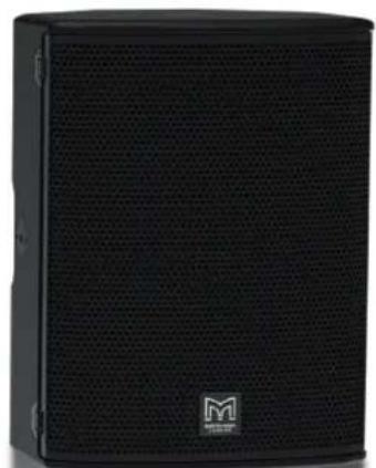
natural_image
Black audio amplifier speaker with mesh grille and 'M' logo (no visible text or symbols beyond branding)
Contents
Rigging
Accessories List. 4
Accessories. 5
Integrated Pole Mount. 9
Touring Yoke Installation Portrait, 10 Installation for FP6 (FP6YPT) & FP8 (FP8YPT). 10
Touring Yoke Installation Landscape. 12 Installation for FP6 (FP6YLT) & FP8 (FP8YLT). 12
Touring Yoke Installation Portrait, 14 Installation for FP12(FP12YPT) & FP15(FP15YPT). 14
Touring Yoke Installation Landscape. 16 Installation for FP12(FP12YLT) & FP15(FP15YLT). 16
Touring & Install Yoke Installation. 18 Installation for FP4 (FP4Y). 18
Lower Mounting Position. 19
Upper Slot Mounting Position. 20
Yoke Installation Install Portrait. 21 Installation for FP6 (FP6YPI), FP8( FP8YPI), FP12 (FPYPI), FP15 (FP5YPI). 21
Lower Mounting Position Portrait. 22
Upper Mounting Position Portrait. 23
Yoke Installation Install Landscape. 24 Installation for FP6 (FP6YLI), FP8( FP8YLI), FP12 (FPYLI), FP15 (FP5YLI). 24
Lower Mounting Position Landscape. 25
Upper Mounting Position Landscape. 26
Pole Adaptor (ASF20045) Touring Yokes. 27
Installation for FP6, FP8, FP12, FP15. 27
Simple Rigging Bar (SBAR40) Portrait....29 Installation for FP6, FP8, FP12, FP15. 29
Simple Rigging Bar (SBAR40) Landscape. 30 Installation for FP6, FP8, FP12, FP15. 30
Wall Mounting Brackets (WB) Portrait....31 Installation for FP6, FP8, FP12, FP15. 31
Wall Mounting Brackets (WB) Landscape. 34 Installation for FP6, FP8, FP12, FP15. 34
WB Spacers (WB6/8 & WB10/12) Portrait/Landscape. 37 Installation for FP6, FP8, FP12. 37
Driver Rotation FP6. 38
Driver Rotation FP8, FP12, FP15. 39
Rigging
Accessories List.
Part
ASF20045
SBAR40
ASF20071
WB6/8
WB10/12
WB15
FP4Y
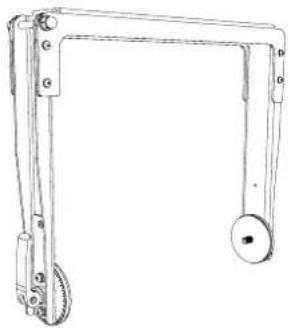
FP6YLI
FP6YPI
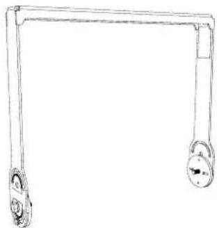
FP6YLT
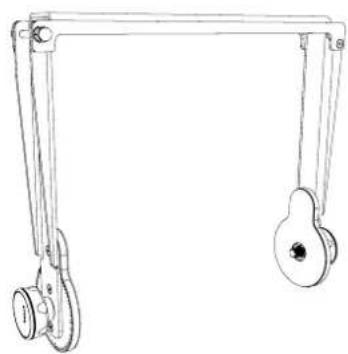
FP6YPT
FP8YLI
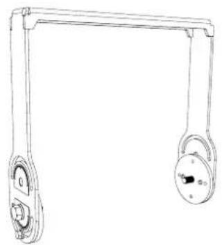
FP8YPI
FP8YLT
FP8YPT
FP12YLI
FP12YPI
FP12YLT
FP12YPT
FP15YLI
FP15YPI
FP15YLT
FP15YPT
Description
Pole mount adoptor for FP4, FP6, FP8, FP12, FP15
Flying Bracket for FP6, FP8, FP12, FP15
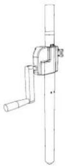
Wind-up telescopic pole
Wall mount bracket for FP6, FP8
Wall mount bracket for FP12
Wall mount bracket for FP15
Touring & install yoke for FP4
Install yoke for FP6 (Landscape)
Install yoke for FP6 (Portrait)
Touring yoke for FP6 (Landscape)
Touring yoke for FP6 (Portrait)
Install yoke for FP8 (Landscape)
Install yoke for FP8 (Portrait)
Touring yoke for FP8 (Landscape)
Touring yoke for FP8 (Portrait)
Install yoke for FP12 (Landscape)
Install yoke for FP12 (Portrait)
Touring yoke for FP12 (Landscape)
Touring yoke for FP12 (Portrait)
Install yoke for FP15 (Landscape)
Install yoke for FP15 (Portrait)
Touring yoke for FP15 (Landscape)
Touring yoke for FP15 (Portrait)
Accessories.
ASF20045 SBAR40
natural_image
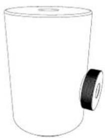
Simple line drawing of a cylindrical container with a side knob (no text or symbols)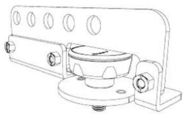
natural_image
Technical line drawing of a mechanical assembly with mounting flanges and a central cylindrical component (no text or symbols)ASF20071 WB6/8
natural_image
Technical line drawing of a mechanical clamp or bracket assembly (no text or symbols)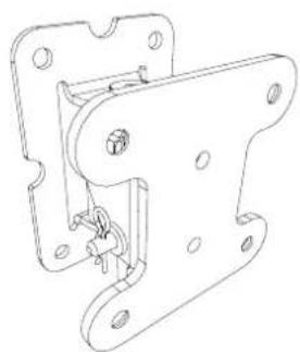
natural_image
Technical line drawing of a mechanical bracket assembly (no text or symbols)WB10/12 WB15
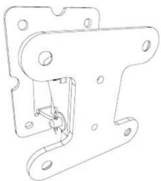
natural_image
Technical line drawing of a mechanical bracket assembly (no text or symbols)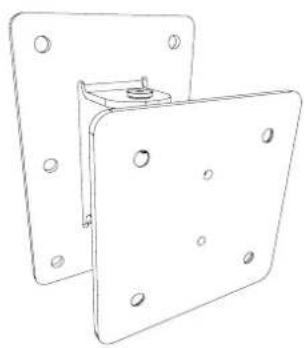
natural_image
Technical line drawing of two metal bracket plates with mounting holes (no text or symbols)FP4Y FP6YLI
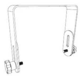
natural_image
Line drawing of a mechanical lever assembly (no text or symbols)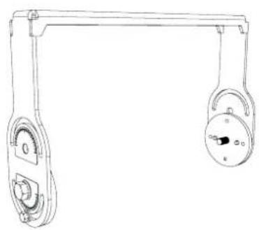
natural_image
Line drawing of a mechanical lifting device with two wheels and a handle (no text or symbols)FP6YPI FP6YLT
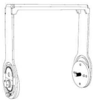
natural_image
Technical line drawing of a mechanical pulley system with two wheels and a handle (no text or symbols)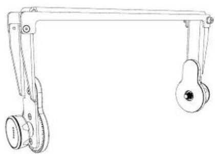
natural_image
Technical line drawing of a mechanical lifting device with two wheels and a handle (no text or symbols)FP6YPT FP8YLI
natural_image
Line drawing of a mechanical lever system with two hanging weights (no text or symbols)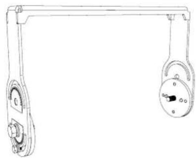
natural_image
Technical line drawing of a mechanical pulley system with two hanging weights (no text or symbols)FP8YPI FP8YLT
natural_image
Line drawing of a mechanical lifting lever with two wheels and a central knob (no text or symbols)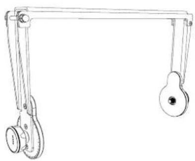
natural_image
Line drawing of a mechanical lifting lever system with two pulleys and a wheel (no text or symbols)FP8YPT FP12YLI
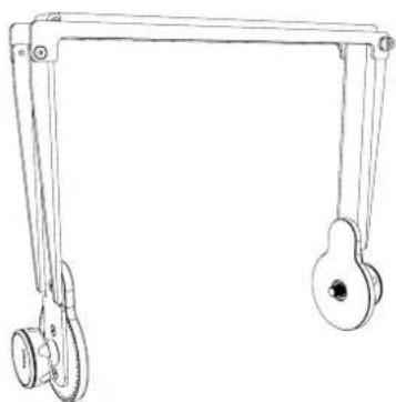
natural_image
Line drawing of a mechanical support frame with two wheels and a handle (no text or symbols)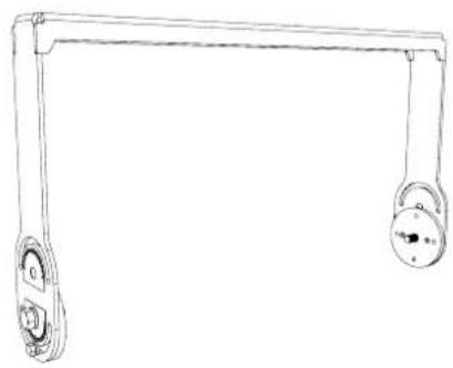
natural_image
Line drawing of a mechanical lever with two pulleys and a handle (no text or symbols)FP12YPI FP12YLT
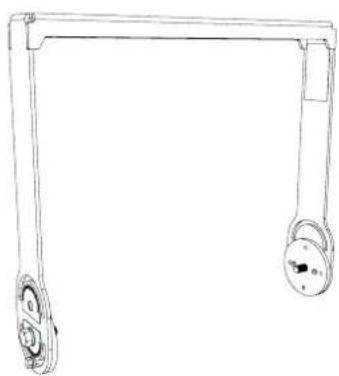
natural_image
Line drawing of a mechanical lever with two wheels and a handle (no text or symbols)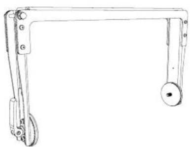
natural_image
Line drawing of a mechanical lever system with two wheels and a handle (no text or symbols)FP12YPT FP15YLI
natural_image
Line drawing of a mechanical linkage with labeled joints (no text or symbols)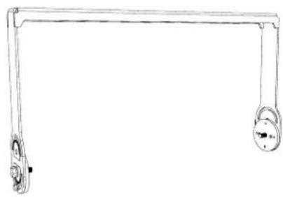
natural_image
Simple line drawing of a horizontal support frame with two circular ends and a central knob (no text or symbols)FP15YPI FP15YLT
natural_image
Line drawing of a simple mechanical lever or support structure with two circular components (no text or symbols)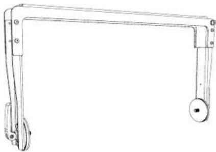
natural_image
Line drawing of a mechanical lever with two wheels and a handle (no text or symbols)FP15YPT
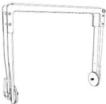
natural_image
Line drawing of a mechanical lever system with no text or symbolsIntegrated Pole Mount.
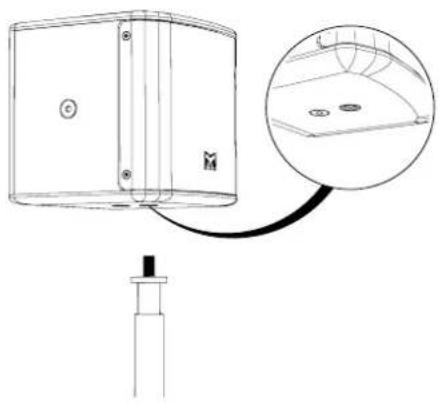
FP4 has a 3/8" insert for a microphone stand.
Align the insert on the FP4 with the Microphone stand. Mount the FP4 to the microphone stand.
natural_image
Technical line drawing of a device with a close-up inset showing internal components (no text or symbols)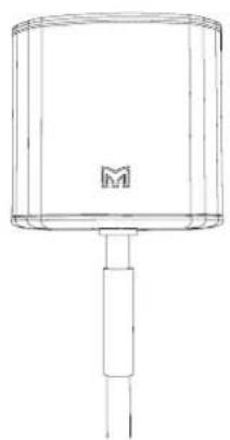
natural_image
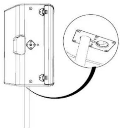
Simple line drawing of a cylindrical device with a handle and a label 'M' on the top (no text or symbols beyond the label)FP6, FP8, FP12 & FP15 have an integrated 35mm dual pole mount for deployment on SX Series subwoofers or speaker stands.
The rear mount sets the angle at 0^ . The front mount sets the angle at 20^ .
natural_image
Technical line drawing of a mechanical housing component with an inset close-up showing a mounting bracket detail (no text or symbols)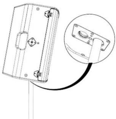
natural_image
Technical line drawing of a mechanical component with a magnified inset showing a close-up detail (no text or symbols)Touring Yoke Installation Portrait.
Installation for FP6 (FP6YPT) & FP8 (FP8YPT).
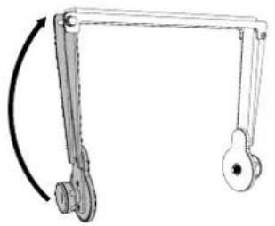
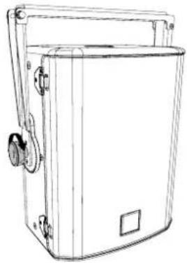
FP6 & FP8 have an integrated M10 mounts for rigging accessories. Quick release touring yokes can be fixed to the mounts without the use of any tools.
Pull the floating arm out before aligning to the mounts on the speaker.
natural_image
Mechanical linkage diagram showing a curved arm and pulley (no text or symbols)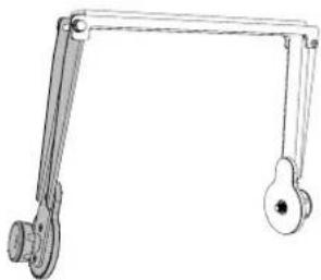
natural_image
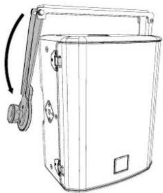
Mechanical linkage diagram showing a lever and handle assembly (no text or symbols)Align the arms to the M10 mounts on the speaker.
natural_image
Line drawing of a mechanical device with a handle and mounting bracket (no text or symbols)Secure the yoke to the speaker using the handwheels.
natural_image
Line drawing of a portable electronic device with handle and control panel (no text or symbols)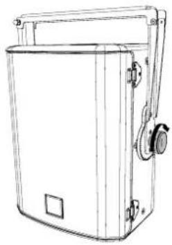
natural_image
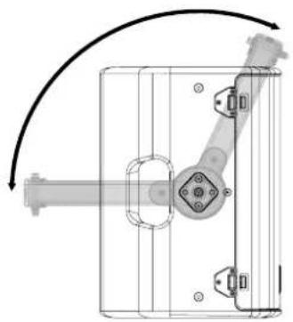
Line drawing of a rectangular electronic device with mounting bracket and side ports (no text or symbols)Set the desired angle for the speaker. Tighten the hand wheels on both sides to secure.
natural_image
Mechanical assembly diagram showing a rotating shaft and housing with mounting holes (no text or symbols)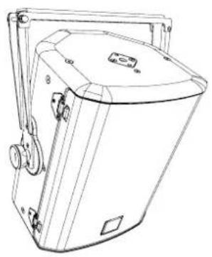
natural_image
Line drawing of a mechanical device with no visible text or symbolsTouring Yoke Installation Landscape.
Installation for FP6 (FP6YLT) & FP8 (FP8YLT).
FP6 & FP8 have an integrated M10 mounts for rigging accessories. Quick release touring yokes can be fixed to the mounts without the use of any tools.
Pull the floating arm out before aligning to the mounts on the speaker.
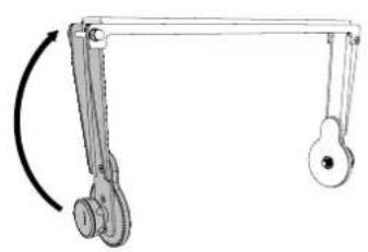
natural_image
Mechanical linkage diagram showing a lever with a curved arrow indicating rotational motion (no text or symbols)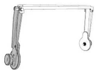
natural_image
Simple line drawing of a mechanical lever system with two curved arms and a handle (no text or symbols)Align the arms to the M10 mounts on the speaker.
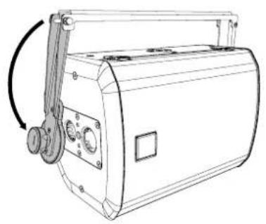
natural_image
Line drawing of a portable radio or megaphone device with no visible text or symbolsSecure the yoke to the speaker using the handwheels.
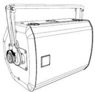
natural_image
Line drawing of a mechanical device with no visible text or symbols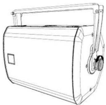
natural_image
Line drawing of a portable electronic device with handle and control panel (no text or symbols)Set the desired angle for the speaker. Tighten the hand wheels on both sides to secure.
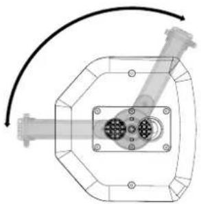
natural_image
Technical diagram of a mechanical assembly with a central component and curved arrow indicating motion (no text or symbols)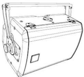
natural_image
Line drawing of a portable electronic device with ports and casing (no text or symbols)Touring Yoke Installation Portrait.
Installation for FP12(FP12YPT) & FP15(FP15YPT).
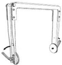
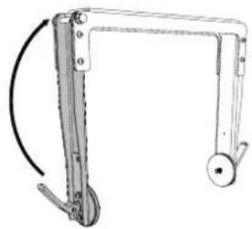
FP12 & FP15 have an integrated M10 mounts for rigging accessories. Quick release touring yokes can be fixed to the mounts without the use of any tools.
Release the clamp levers on both sides of the yoke.
natural_image
Line drawing of a mechanical frame with two wheels and a handle (no text or symbols)Pull the floating arm out before aligning to the mounts on the speaker.
natural_image
Mechanical linkage diagram showing a frame with levers and weights (no text or symbols)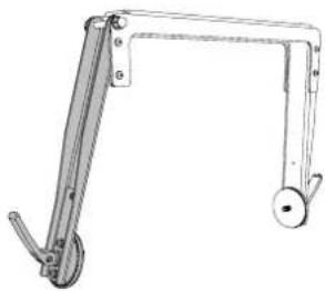
natural_image
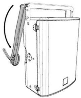
Technical line drawing of a mechanical linkage or support structure (no text or symbols)Align the arms to the M10 mounts on the speaker. Secure the yoke to the speaker using the clamp levers on both sides.
natural_image
Line drawing of a mechanical device with a lever mechanism (no text or symbols)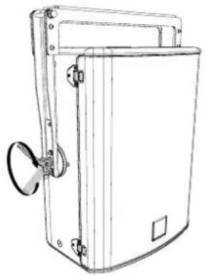
natural_image
Line drawing of a rectangular electronic device with a handle and mounting bracket (no text or symbols)Set the desired angle for the speaker. Tighten the clamp levers on both sides to secure.
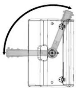
natural_image
Pure mechanical diagram showing a lever mechanism inside a rectangular frame, with no text or symbols present.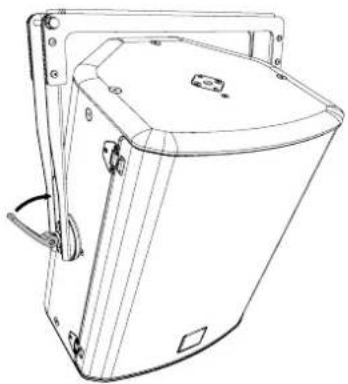
natural_image
Line drawing of a mechanical device with mounting brackets and a central lid (no text or symbols)Touring Yoke Installation Landscape.
Installation for FP12(FP12YLT) & FP15(FP15YLT).
FP12 & FP15 have an integrated M10 mounts for rigging accessories. Quick release touring yokes can be fixed to the mounts without the use of any tools.
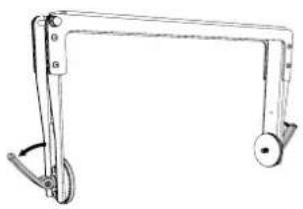
Release the clamp levers on both sides of the yoke.
natural_image
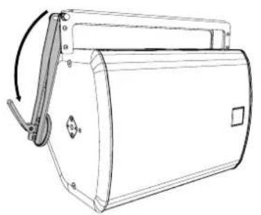
Technical line drawing of a mechanical lever or bracket with handle and pivot (no text or symbols)Pull the floating arm out before aligning to the mounts on the speaker.
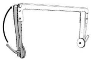
natural_image
Mechanical linkage diagram showing a frame with curved joints and a wheel (no text or symbols)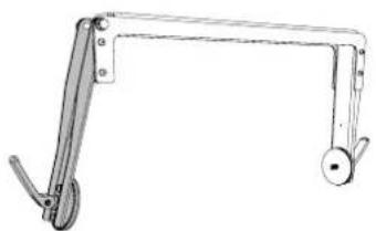
natural_image
Technical line drawing of a mechanical lever mechanism (no text or symbols)Align the arms to the M10 mounts on the speaker. Secure the yoke to the speaker using the clamp levers on both sides.
natural_image
Line drawing of a portable electronic device with handle and control panel (no text or symbols)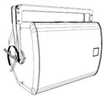
natural_image
Line drawing of a cylindrical mechanical device with handle and mounting bracket (no text or symbols)Set the desired angle for the speaker. Tighten the clamp levers on both sides to secure.
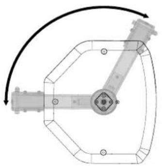
natural_image
Mechanical linkage diagram showing a symmetrical frame with joints and a central hub, no text or symbols present.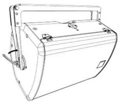
natural_image
Line drawing of a mechanical device with handle and mounting bracket (no text or symbols)Touring & Install Yoke Installation.
Installation for FP4 (FP4Y).
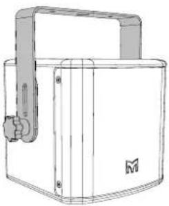
The FP4 has integrated M6 mounts for the FP4Y yoke assembly. The quick release yoke can be secured to the mounts with the use of any tools.
The FP4Y has a lower mounting hole and a slot above for close coupled installation.
Lower mounting position allows for any vertical angle desired.
Upper mounting slot reduces the gap between the yoke and the speaker for close coupled mounting and low ceilings.
Close coupled has limited vertical angle adjustment.
natural_image
Line drawing of a mechanical device with handle and mounting bracket (no text or symbols)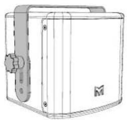
natural_image
Technical line drawing of a mechanical device with a handle and mounting bracket (no text or symbols)Lower Mounting Position.
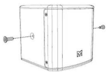
Remove the M6 fixings from the sides of the cabinet.
Secure the yoke to the speaker using the clamp levers on both sides.
natural_image
Technical line drawing of a rectangular device with mounting holes and a central panel (no text or symbols)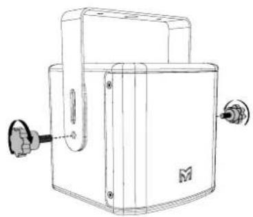
natural_image
Technical line drawing of a mechanical device with mounting flanges and a central housing (no text or symbols)Set the desired angle for the speaker. Tighten the thumb wheels on both sides to secure.
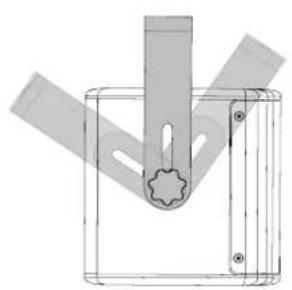
natural_image
Pure technical diagram of a mechanical component with no text, numbers, or symbols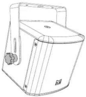
natural_image
Line drawing of a portable water dispenser with handle and control panel (no text or symbols)Upper Slot Mounting Position.
Remove the M6 fixings from the sides of the cabinet.
Secure the yoke to the speaker using the clamp levers on both sides.
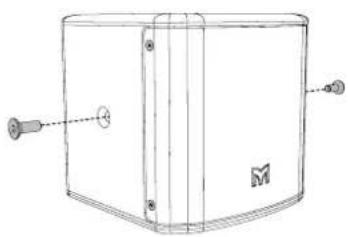
natural_image
Technical line drawing of a rectangular enclosure with mounting holes and a central vertical structure (no text or symbols)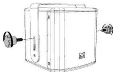
natural_image
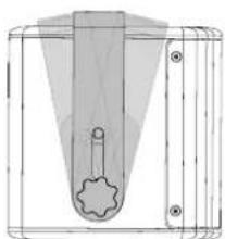
Technical line drawing of a mechanical device with two ports and a base plate (no text or symbols)Set the desired angle for the speaker. Tighten the thumb wheels on both sides to secure.
natural_image
Technical line drawing of a mechanical component with a central gear-like feature and mounting holes (no text or symbols)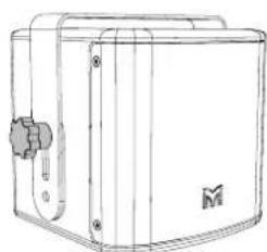
natural_image
Line drawing of a mechanical device with a central handle and mounting bracket (no text or symbols)Yoke Installation Install Portrait.
Installation for FP6 (FP6YPI), FP8( FP8YPI), FP12 (FPYPI), FP15 (FP5YPI).
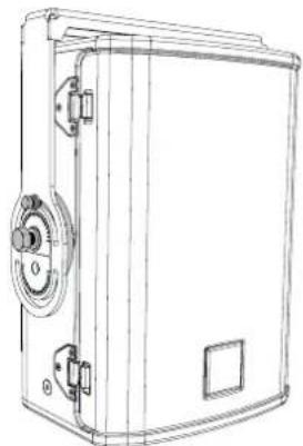
Flexpoint install yokes can be fixed to the M10 mounting points, but tools are required. A 17mm socket or spanner for the yoke and 10mm socket or spanner to securely lock the yoke angle.
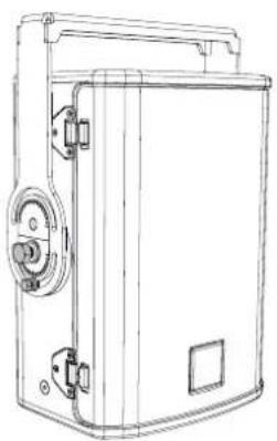
There are two available mounting postions for the install yokes.
Lower mounting position allows for any vertical angle desired.
natural_image
Line drawing of a mechanical enclosure or enclosure with mounting brackets and a central handle (no text or symbols)Upper mounting position reduces the gap between the yoke and the speaker for close coupled mounting and low ceilings.
Close coupled mounting has limited vertical angle adjustment.
natural_image
Line drawing of a mechanical device with no visible text or symbolsLower Mounting Position Portrait.
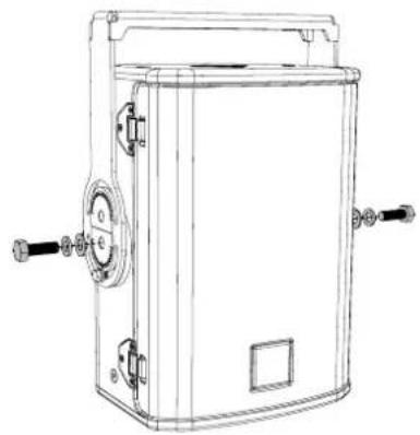
Position the friction pads and fixings on the lower mounting holes and secure into place with a 17mm socket or spanner.
natural_image
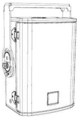
Line drawing of a mechanical device with handle, valve, and mounting feet (no text or symbols)Set the desired angle for the speaker.
natural_image
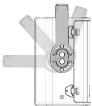
Line drawing of a rectangular industrial machine with control panel and door (no text or symbols)Lock into place using a 17mm socket or spanner for the M10 mounting points (both sides) and a 10mm for the secondary fixing.
natural_image
Technical line drawing of a mechanical component with no visible text or symbols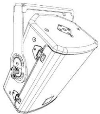
natural_image
Technical line drawing of a mechanical device with mounting flanges and a central housing (no text or symbols)Upper Mounting Position Portrait.
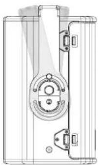
Position the friction pads and fixings on the upper mounting holes and secure into place with a 10mm socket or spanner.
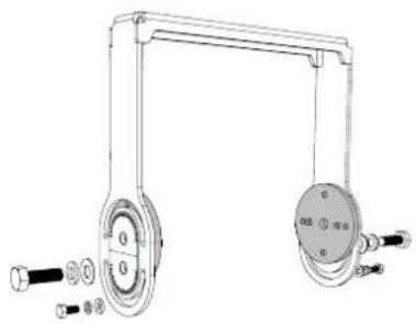
natural_image
Technical line drawing of a mechanical lifting device with two wheels and adjustment knobs (no text or symbols)Attach to the cabinet with a 17mm socket or spanner.
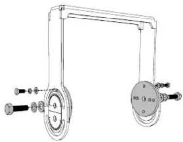
natural_image
Technical line drawing of a mechanical device with two circular components and adjustment knobs (no text or symbols)Set the desired angle, which is limited to the yokes close proximity to the cabinet.
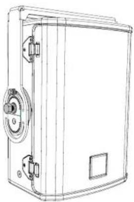
natural_image
Line drawing of a rectangular industrial machine or enclosure with mounting flanges and control buttons (no text or symbols)Lock into place using a 17mm socket or spanner for the M10 mounting points (both sides) and a 10mm for the secondary fixing.
natural_image
Technical line drawing of a mechanical component with no visible text or symbols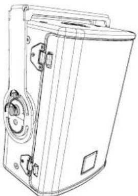
natural_image
Line drawing of a mechanical device with no visible text or symbolsYoke Installation Install Landscape.
Installation for FP6 (FP6YLI), FP8( FP8YLI), FP12 (FPYLI), FP15 (FP5YLI).
Flexpoint install yokes can be fixed to the M10 mounting points, but tools are required. A 17mm socket or spanner for the yoke and 10mm socket or spanner to securely lock the yoke angle.
There are two available mounting postions for the install yokes.
Lower mounting position allows for any vertical angle desired.
Upper mounting position reduces the gap between the yoke and the speaker for close coupled mounting and low ceilings.
Close coupled mounting has limited vertical angle adjustment.
natural_image
Line drawing of a portable electronic device with handle and control panel (no text or symbols)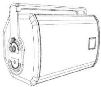
natural_image
Technical line drawing of a cylindrical mechanical device with mounting flanges and a central hub (no text or symbols)Lower Mounting Position Landscape.
Position the friction pads and fixings on the lower mounting holes and secure into place with a 17mm socket or spanner.
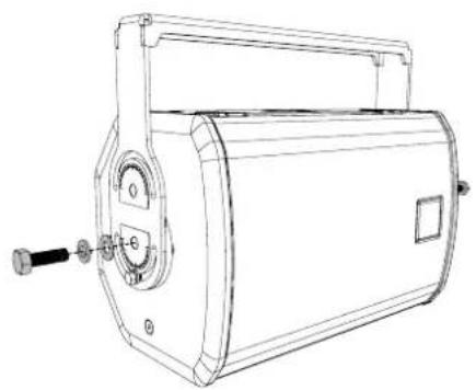
natural_image
Line drawing of a portable radio or megaphone device with handle and control knob (no text or symbols)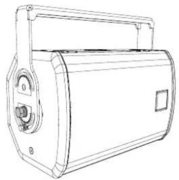
natural_image
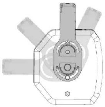
Line drawing of a portable electronic device with handle and control panel (no text or symbols)Set the desired angle for the speaker. Lock into place using a 17mm socket or spanner for the
M10 mounting points (both sides) and a 10mm for the secondary fixing.
natural_image
Technical line drawing of a mechanical component with no visible text or symbols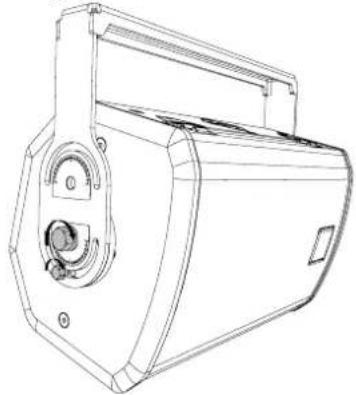
natural_image
Technical line drawing of a mechanical device with no visible text or symbolsUpper Mounting Position Landscape.
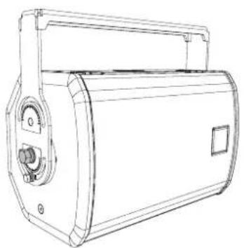
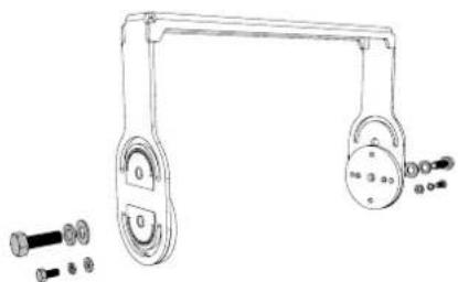
Position the friction pads and fixings on the upper mounting holes and secure into place with a 10mm socket or spanner.
natural_image
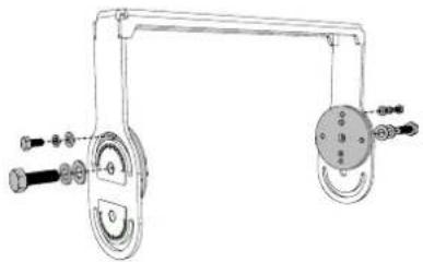
Technical line drawing of a mechanical lifting bracket with bolted components and mounting holes (no text or labels)Attach to the cabinet with a 17mm socket or spanner.
natural_image
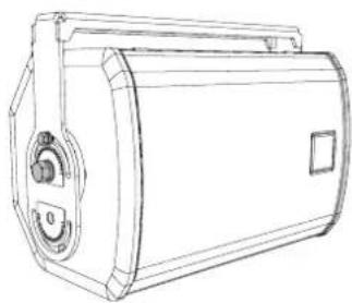
Mechanical pulley system diagram with two wheels and connecting rods (no text or labels)Set the desired angle, which is limited to the yokes close proximity to the cabinet.
natural_image
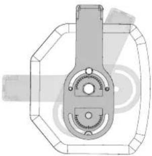
Line drawing of a cylindrical mechanical device with mounting flanges and central hub (no text or symbols)Lock into place using a 17mm socket or spanner for the M10 mounting points (both sides) and a 10mm for the secondary fixing.
natural_image
Technical line drawing of a mechanical component with no visible text or symbols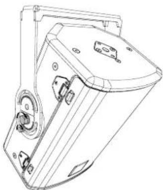
natural_image
Technical line drawing of a mechanical device with mounting flanges and control buttons (no text or symbols)Pole Adaptor (ASF20045) Touring Yokes.
Installation for FP6, FP8, FP12, FP15.
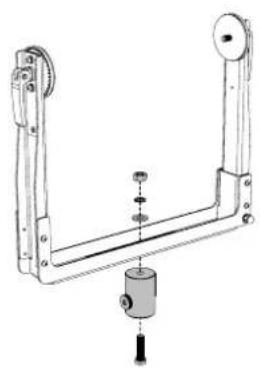
Secure the pole mount adaptor to the yoke using the included fixings.
natural_image
Mechanical linkage assembly diagram with no visible text or symbols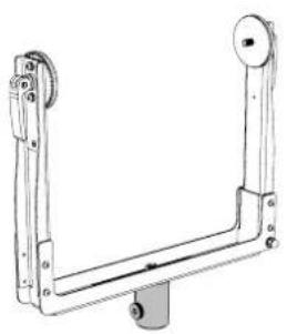
natural_image
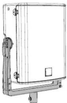
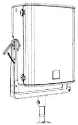
Technical line drawing of a mechanical support bracket with mounting holes and a central base (no text or symbols)Attached the speaker to the yoke as per instructions starting on page 12.
Mount onto the pole and tighten the thumb screw on the pole mount adaptor to secure.
natural_image
Technical line drawing of a rectangular enclosure with mounting brackets and mounting holes (no text or symbols)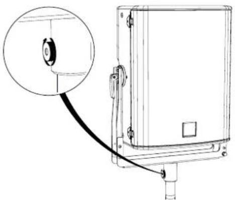
natural_image
Technical line drawing of an electrical enclosure with a cable and a magnified inset showing a circular component (no text or symbols)Release the clamp levers on both sides of the yoke. Rotate the cabinet to the dired angle.
natural_image
Technical line drawing of a rectangular enclosure with mounting base and side-mounted components (no text or symbols)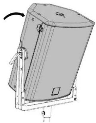
natural_image
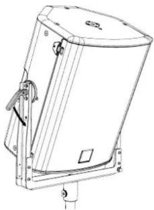
Technical line drawing of a mechanical device with mounting brackets and a curved arrow indicating rotation (no text or symbols)Tighten clamp levers to secure the cabinet in place.
natural_image
Technical line drawing of a mechanical device with mounting bracket and control panel (no text or symbols)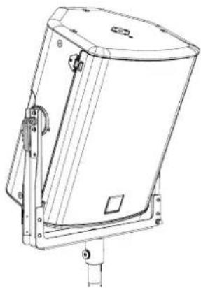
natural_image
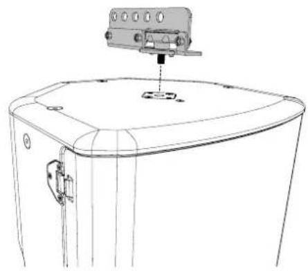
Technical line drawing of a mechanical enclosure or enclosure with mounting brackets and a central cover (no text or symbols)Simple Rigging Bar (SBAR40) Portrait.
Installation for FP6, FP8, FP12, FP15.
Locate the SBAR40 on to the M10 mounting plate. Tighten hand wheel to secure.
natural_image
Technical line drawing of a mechanical device with mounting bracket and control panel (no text or symbols)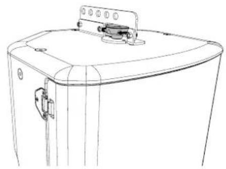
natural_image
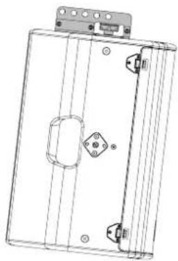
Line drawing of a front-loading washing machine (no text or symbols)The SBAR40 can be mounted at the rear for negative angles.
natural_image
Technical line drawing of a rectangular electronic device with mounting holes and internal components (no text or symbols)Mounted at the front for positive angles.
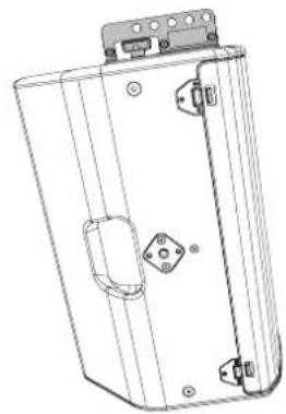
natural_image
Technical line drawing of a rectangular electronic device with mounting brackets and internal components (no text or symbols)Simple Rigging Bar (SBAR40) Landscape.
Installation for FP6, FP8, FP12, FP15.
Locate the SBAR40 on to the M10 mounting plate. Tighten hand wheel to secure.
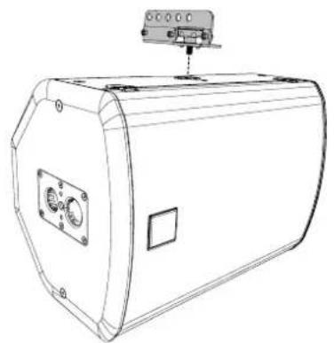
natural_image
Technical line drawing of a cylindrical industrial device with mounting bracket and control panel (no text or symbols)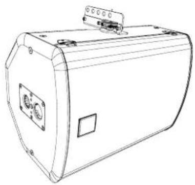
natural_image
Line drawing of a rectangular electronic device with a control panel and mounting bracket (no text or symbols)The SBAR40 can be mounted at the rear for negative angles.
Mounted at the front for positive angles.
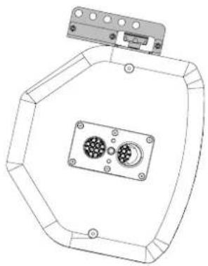
natural_image
Technical line drawing of a mechanical component with two circular ports and mounting bracket (no text or symbols)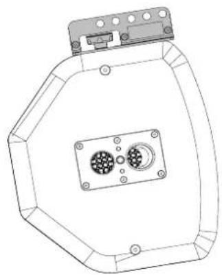
natural_image
Technical line drawing of a mechanical component with hexagonal base and central mounting holes (no text or symbols)Wall Mounting Brackets (WB) Portrait.
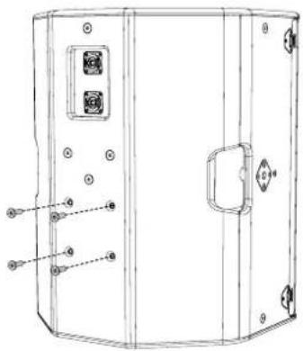
Installation for FP6, FP8, FP12, FP15.
Remove the middle and lower fixings from the cabinet.
natural_image
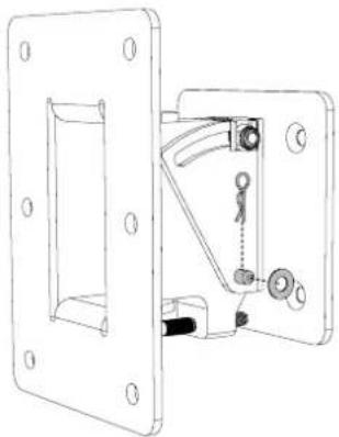
Technical line drawing of a mechanical device with mounting holes and a handle (no text or symbols)Remove the R-Clip and washer from the WB bracket.
natural_image
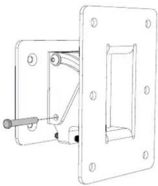
Technical line drawing of a mechanical latch or bracket assembly (no text or symbols)Remove the pivot pin from the WB assembly.
natural_image
Technical line drawing of a mechanical clamp or bracket assembly (no text or symbols)Separate the two parts of the WB bracket.
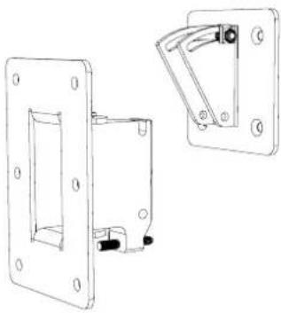
natural_image
Technical line drawing of two mechanical components with mounting holes and a handle (no text or symbols)Attach the speaker part of the WB assembly to the cabinet, using the fixings that were removed from the cabinet.
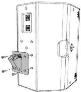
natural_image
Technical line drawing of a mechanical device with a bracket and mounting holes (no text or symbols)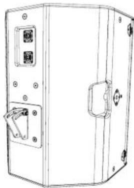
natural_image
Line drawing of a rectangular electronic device with switches and buttons (no text or symbols)Attach the wall part of the WB assembly to a suitable structure using rated fixings.
Note: These fixings are not supplied by Martin Audio.
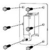
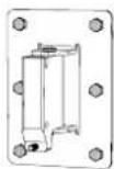
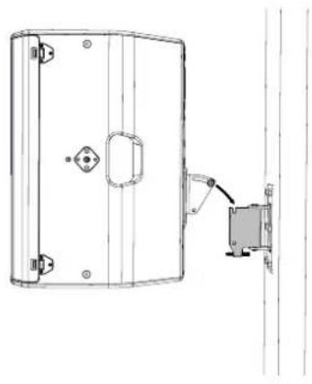
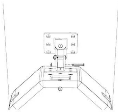
Offer the speaker up to the wall bracket and hook the horizontal bolt into the curved slot.
natural_image
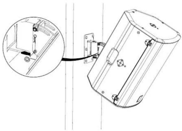
Technical line drawing of a mechanical component with mounting holes and a vertical guide rail (no text or symbols)Replace the washer and R-Clip to sucure the pivot pin in place.
natural_image
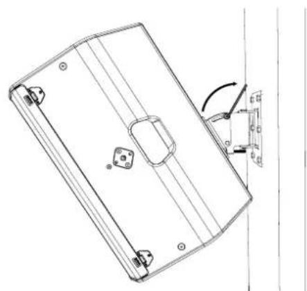
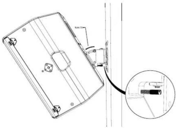
Technical line drawing of a mechanical device with an inset showing a close-up of a component detail (no text or symbols present)Once the vertical angle is set tighten the top bolt with a 5mm hex tool.
natural_image
Technical line drawing of a rectangular panel with mounting holes and a curved arrow indicating rotation (no text or symbols)Replace the pivot pin.
natural_image
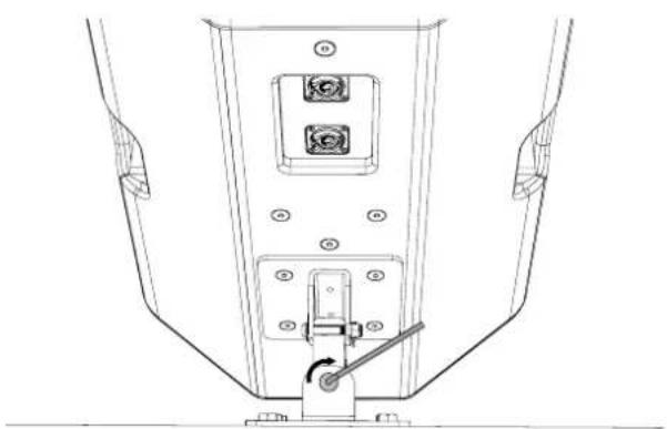
Technical line drawing of a mechanical clamp or support structure with mounting base (no text or symbols)Set the desired downward tilt angle and hold in place with the grub screw.
Set the hozontal angle, then secure using a 5mm hex tool.
natural_image
Technical line drawing of a mechanical assembly with mounting holes and a central switch (no text or symbols)Wall Mounting Brackets (WB) Landscape.
Installation for FP6, FP8, FP12, FP15.
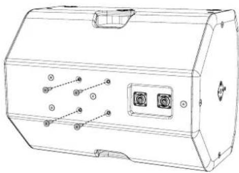
Remove the middle and lower fixings from the cabinet.
natural_image
Technical line drawing of a device casing with internal components and mounting holes (no text or symbols)Remove the R-Clip and washer from the WB bracket.
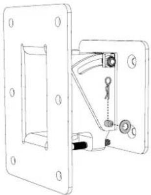
natural_image
Technical line drawing of a mechanical latch or bracket assembly (no text or symbols)Remove the pivot pin from the WB assembly. Separate the two parts of the WB bracket.
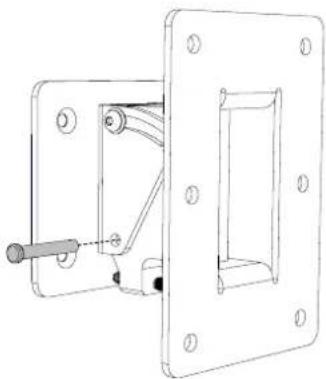
natural_image
Technical line drawing of a mechanical clamp or bracket assembly (no text or symbols)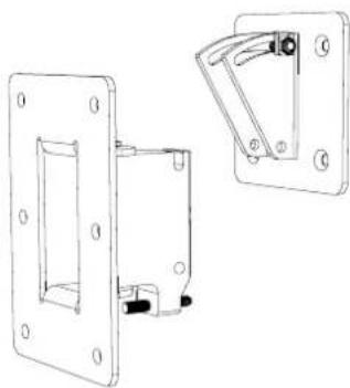
natural_image
Technical line drawing of two mechanical components with mounting holes and a handle (no text or symbols)Attach the speaker part of the WB assembly to the cabinet, using the fixings that were removed from the cabinet.
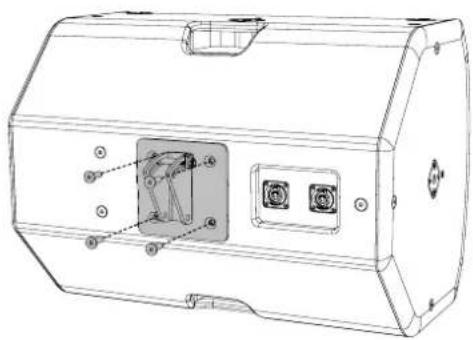
natural_image
Technical line drawing of a device casing with internal components and mounting holes (no text or symbols)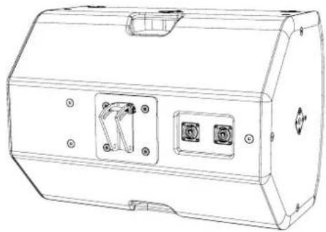
natural_image
Technical line drawing of a rectangular electronic device with two internal components and mounting holes (no text or symbols)Attach the wall part of the WB assembly to a suitable structure using rated fixings.
Note: These fixings are not supplied by Martin Audio.
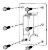
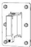
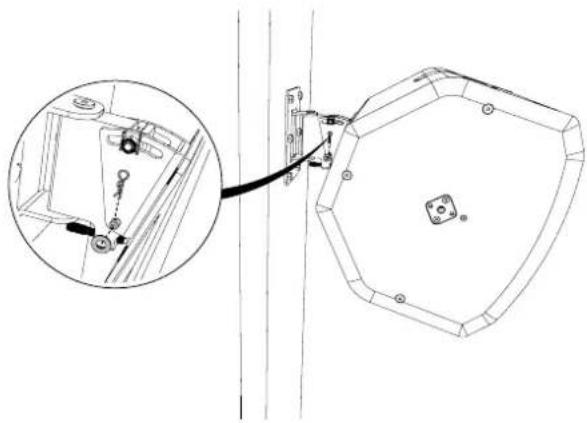
Offer the speaker up to the wall bracket and hook the horizontal bolt into the curved slot.
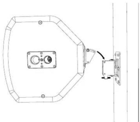
natural_image
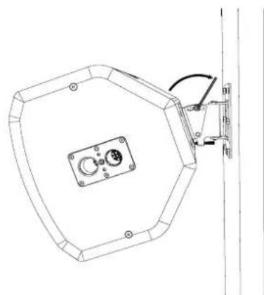
Technical line drawing of a mechanical assembly with a central housing and connected bracket (no text or symbols)Replace the washer and R-Clip to sucure the pivot pin in place.
natural_image
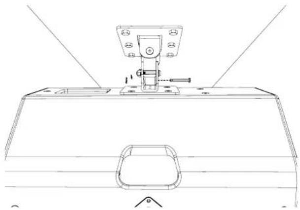
Technical line drawing of a mechanical assembly with an inset showing a close-up of a component detail (no text or symbols)Once the vertical angle is set tighten the top bolt with a 5mm hex tool.
natural_image
Technical line drawing of a hexagonal mechanical component with mounting holes and a vertical rail (no text or symbols)Replace the pivot pin.
natural_image
Technical line drawing of a mechanical assembly with no visible text or symbolsSet the desired downward tilt angle and hold in place with the grub screw.
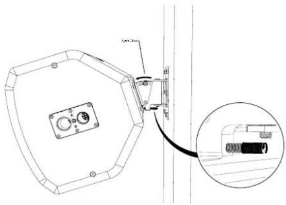
Set the hozontal angle, then secure using a 5mm hex tool.
natural_image
Technical line drawing of a mechanical device with mounting bracket and control panel (no text or symbols)WB Spacers (WB6/8 & WB10/12) Portrait/Landscape.
Installation for FP6, FP8, FP12.
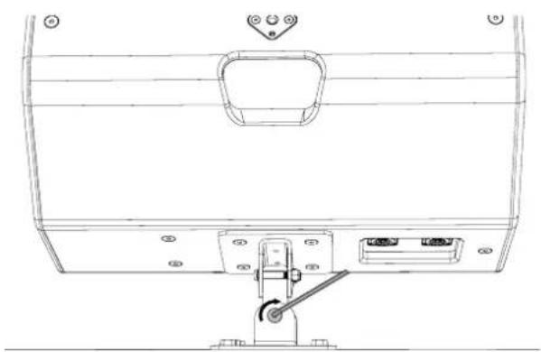
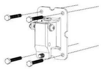
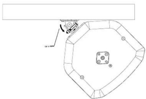
WB6/8 & WB10/12 are designed to be unobtrusive low profile wall brackets for neat and professional installation. When mounted the speaker sits very close to the wall and although maximum tilt angle is available, there is a limit to how much horizontal panning can be achieved.
Included with the WB brackets are two spacers, these can be inserted between the bracket and the wall. The spacers allow for more horizontal adjustment with or without vertical adjustment applied.
Attach the wall part of the WB without spacers.
Attach the wall part of the WB with spacers.
natural_image
Technical line drawing of a mechanical clamp or bracket assembly with multiple bolted joints (no text or symbols)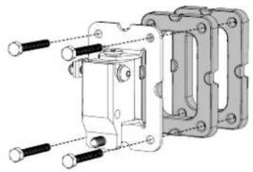
natural_image
Mechanical assembly diagram showing a housing with bolts and mounting brackets (no text or labels)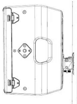
natural_image
Technical line drawing of a mechanical lock or latch component (no text or symbols)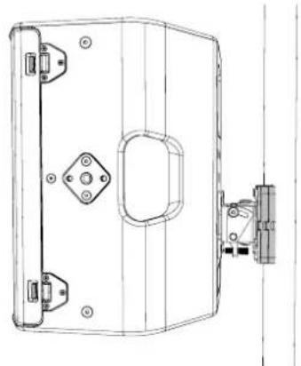
natural_image
Technical line drawing of a mechanical housing or enclosure with mounting holes and a side-mounted bracket (no text or symbols)Max angle without spacers up to 44 degrees. Max angle with spacers up to 52 degrees.
natural_image
Technical line drawing of a mechanical assembly with a central component and mounting holes (no text or symbols)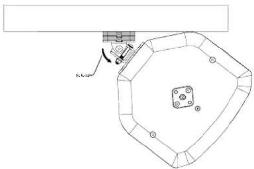
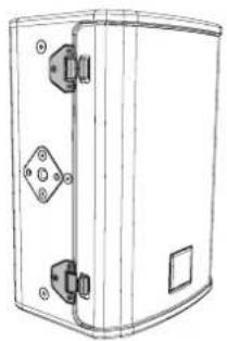
Driver Rotation FP6.
Remove the grille by pressing the quick release catches.
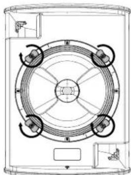
Loosen the captive driver fixings until they are completely free of the cabinet inserts.
natural_image
Technical line drawing of a rectangular enclosure with mounting holes and a central diamond-shaped element (no text or symbols)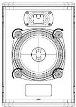
natural_image
Technical line drawing of a mechanical component with no visible text or symbolsLift the driver free of the recess in the baffle using two of the driver fixings and rotate through 90 degrees.
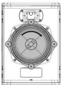
natural_image
Technical line drawing of a mechanical component with mounting holes and central hub (no text or symbols)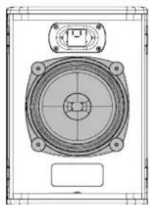
natural_image
Technical line drawing of a speaker component with mounting holes and central hub (no text or symbols)Tighten all thumb wheels to secure the driver.
Replace the grille by lining up the grille slots and pushing into place on both sides.
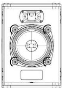
natural_image
Technical line drawing of a mechanical component with mounting holes and central hub (no text or symbols)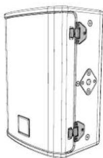
natural_image
Technical line drawing of a rectangular enclosure with mounting brackets and a central diamond-shaped component (no text or symbols)Driver Rotation FP8, FP12, FP15.
Remove the grille by pressing the quick release catches.
Loosen the captive driver fixings until they are completely free of the cabinet inserts.
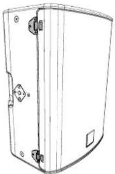
natural_image
Line drawing of a rectangular electronic device with mounting holes and a curved top panel (no text or symbols)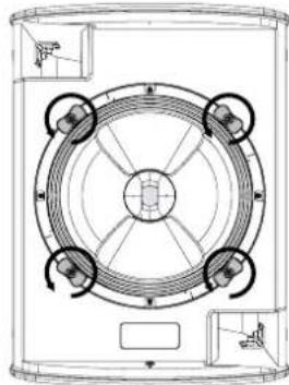
natural_image
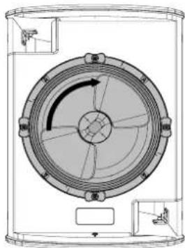
Technical line drawing of a circular mechanical component with four symmetrical arms and central hub (no text or symbols)Lift the driver free of the recess in the baffle using two of the driver fixings and rotate through 90 degrees.
natural_image
Technical line drawing of a circular mechanical component with internal rotation arrow (no text or symbols)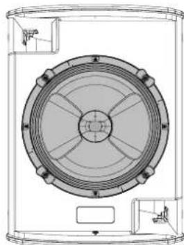
natural_image
Technical line drawing of a circular mechanical component with internal divisions and mounting holes (no text or symbols)Tighten all thumb wheels to secure the driver.
Replace the grille by lining up the grille slots and pushing into place on both sides.
natural_image
Technical line drawing of a circular mechanical component with four directional arrows indicating rotation or flow (no text or symbols)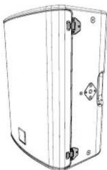
natural_image
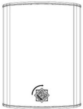
Line drawing of a white cylindrical device with mounting holes and a side panel (no text or symbols)Pull and rotate the badge through 90 degrees for landscape deployment.
natural_image
Simple line drawing of a cylindrical container with a small circular button and arrow, no text or symbols present.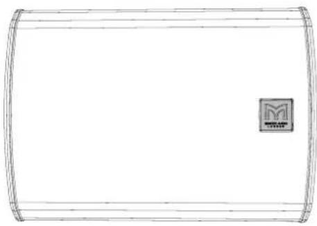
natural_image
Simple line drawing of a rectangular container with rounded ends and a small square logo in the top-right corner (no text or symbols)Martin Audio Limited
Century Point
Halifax Road
Cressex Business Park
FOR SALES ENQUIRIES:
High Wycombe
Buckinghamshire
HP12 3SL
England
UK
Telephone: +44 (0)1494 535312
E-mail: info@martin-audio.com
NORTH AMERICA
Telephone: 323-381-5310
martin-audio.com
All information is Copyright © 2023 Martin Audio Ltd.
Martin Audio, the Martin Audio logo are registered trademarks of Martin Audio Ltd. in the United Kingdom, United States and other countries; all other Martin Audio trademarks are the property of Martin Audio Ltd.

MARTIN AUDIO
LONDON
- Contents
- Rigging
- Part
- Description
- Accessories.
- Integrated Pole Mount.
- Touring Yoke Installation Portrait.
- Touring Yoke Installation Landscape.
- Touring & Install Yoke Installation.
- Lower Mounting Position.
- Upper Slot Mounting Position.
- Yoke Installation Install Portrait.
- Lower Mounting Position Portrait.
- Upper Mounting Position Portrait.
- Yoke Installation Install Landscape.
- Lower Mounting Position Landscape.
- Upper Mounting Position Landscape.
- Pole Adaptor (ASF20045) Touring Yokes.
- Simple Rigging Bar (SBAR40) Portrait.
- Simple Rigging Bar (SBAR40) Landscape.
- Wall Mounting Brackets (WB) Portrait.
- Wall Mounting Brackets (WB) Landscape.
- WB Spacers (WB6/8 & WB10/12) Portrait/Landscape.
- Driver Rotation FP6.
- Driver Rotation FP8, FP12, FP15.
- Martin Audio Limited
- martin-audio.com
Brand : Martin Audio
Model : FlexPoint FP6
Category : Audio