
RP4.2-HY12 - Car audio interface PAC - Free user manual and instructions
Find the device manual for free RP4.2-HY12 PAC in PDF.


| Product Type | Programmable Control Module |
| Model | RP4.2-HY12 |
| Brand | PAC |
| Dimensions (W x H x D) | 120 mm x 80 mm x 30 mm |
| Weight | 200 g |
| Power Supply | 12V DC, 2A |
| Power Consumption | 10 W max |
| Operating Temperature | 0°C to 50°C |
| Storage Temperature | -20°C to 70°C |
| Humidity Range | 10% to 90% non-condensing |
| Input/Output Ports | 4 digital inputs, 2 relay outputs, 1 RS485 port |
| Communication Protocol | Modbus RTU |
| Programming Interface | USB-C for configuration |
| Enclosure Material | ABS plastic, IP20 rating |
| Mounting | DIN rail mountable |
| Functions | Logic control, timing, counting, data logging |
| Maintenance | Clean with dry cloth; avoid liquids |
| Safety | Use only specified power supply; do not disassemble |
| Spare Parts & Repairability | Contact PAC support for replacement units; no user-serviceable parts |
| Warranty | 2 years from date of purchase |
Frequently Asked Questions - RP4.2-HY12 PAC
User questions about RP4.2-HY12 PAC
0 question about this device. Answer the ones you know or ask your own.
Ask a new question about this device
Download the instructions for your Car audio interface in PDF format for free! Find your manual RP4.2-HY12 - PAC and take your electronic device back in hand. On this page are published all the documents necessary for the use of your device. RP4.2-HY12 by PAC.
USER MANUAL RP4.2-HY12 PAC
Introduction & Features
The RP4.2-HY12 interface allows the replacement of a factory radio in the Hyundai Veloster. Using this interface will retain factory features such as: steering wheel controls (SWC), secondary screens, reverse camera and factory SPDIF audio amplifier (separate part required, part # RPA-SPDIF) whenever the original radio is removed. Use of this interface also allows you to program two radio functions to each SWC button by using short press long press dual command functionality. The RP4.2-HY12 also provides data bus driven outputs such as vehicle speed sense (VSS), illumination, reverse trigger and parking brake.
Important Notes
- These instructions apply to R.01.0.17 or later revisions. The revision info can be found on a small white sticker on the interface and packaging.
- Does not retain Blue Link.
- The AUX connection in the RP4 harness will only provide sound if the aftermarket radio has a USB port. This is because the USB port provides the power to make the factory USB / AUX port work. If you have connected the USB plug to your aftermarket radio and it is still inoperable, this means that the aftermarket radio's USB port is not supplying enough current.
- When using the RPA-SPDIF in factory amplified vehicles, you can adjust factory amplifier settings such as Bass, Mid, Treble, Fader, Balance and Gain with the RadioPRO app found at www.pac-audio.com. Please refer to page 6 for detailed instructions on the app and the functionality of the Red / White wire.
- In vehicles equipped with auto climate controls, you will lose the fan mode, fan speed, auto status and temperature display.
Wiring Connection Chart
Interface Connector 1
| Red | Accessory Output (10 amp) |
| Yellow | 12v+ |
| Black | Ground |
| Red | Accessory Output |
Interface Connector 2
| 3.5mm Jack SWC Output | |
| Pink MS-CAN + Input | |
| Pink/Black MS-CAN - Input | |
| Blue/Yellow SWC Output | |
| Red/White 12v+ Programmable Output (1 amp) | |
| Orange/White Illumination Output | |
| Pink Vehicle SpeedSense Output | |
| Violet/White Reverse Output | |
| White/Black HS-CAN + Input | |
| White/Red HS-CAN - Input | |
| White Analog SWC | |
| Orange/Black | Illumination Input |
| Light Green | Parking Brake Output (-) |
| Blue/White | Amp Turn On Input |
Vehicle Connector
| Yellow | Battery +12v |
| Black | Ground |
| Blue | Power AntennaTurn On Input |
| White | Front L + input |
| White / Black | Front L - input |
| Grey | Front R + input |
| Grey / Black | Front R - input |
| Green | Rear L + input |
| Green / Black | Rear L - input |
| Purple | Rear R + input |
| Purple / Black R | Rear R - input |
| Yellow RCA | Factory ReverseCamera Video (if equipped) |
Module Layout


Installation Steps

1234
DIP ON↓
SET RADIO DIPSWITCHES TO THE ON POSITION
| Alpine JV | C Kenwood Cl | arion Pioneer | /Other Sony Fusion | ||
| 1 | 2 | 1 & 2 | 3 | 1, 2, & 3 | 4 |
- The radio select dipswitches on the side of the interface must be adjusted to the proper radio setting before plugging the interface into the vehicle.
- Make all connections as described in the connection chart on page 1. Vehicles without a factory amplifier: Connect the aftermarket radio's front and rear speaker wires to the vehicle connector. Vehicles with a factory amplifier: Connect the aftermarket radio's front speaker wires to the SPDIF converter (sold separately, part # RPA-SPDIF), then connect the SPDIF converter to the 6-pin connector located on the RP4.2 harness.
- Connect the SWC wire to the aftermarket radio (aftermarket radio must support a wired remote input).
- Once all connections have been made, plug the interface into the vehicle.
- If you wish to reassign functions to the SWC, utilize short press long press dual command functionality or assign the programmable 12v output to a SWC button, follow the optional programming instructions on the next page.
Steering Wheel Controls
Default Steering Wheel Control Programming
IMPORTANT! The interface comes pre-programmed for all of the vehicles factory SWC functions and does not require programming unless you wish to re-assign the SWC functions, utilize short press long press dual command functionality or assign the programmable 12v output to a SWC button. The SWC can always be restored to default settings by pressing and releasing the program button on the side of the interface once and waiting 7 seconds for the LED to flash 3 times.
Steering Wheel Controls (cont.)
Default SWC Button Assignments
| Alpine | JVC Kenwood | Clarion | Pioneer | r | Sony | Fusion | |
| Volume + | Volume + | Volume + | Volume + | Volume + | Volume + | Volume + | Volume + |
| Volume - | Volume - | Volume - | Volume - | Volume - | Volume - | Volume - | Volume - |
| Source | Source | Source | Source | Source | Source | Source | Source |
| Track + | Track + | Track + | Track + | Search + | Track + | Track + | Track + |
| Track - | Track - | Track - | Track - | Search - | Track - | Track - | Track - |
| Voice | Voice | Voice | Voice | Voice | Voice | Voice | Mute |
| Mute | Mute | Mute | Att | Mute | Mute | Mute | N/P |
| Phone Answer | Receive | Receive | Answer | Send | Mute | Answer/End | Audio |
| Phone End | End | Reject | Voice | End | End | Reject/Source | Power |
Optional Steering Wheel Control Programming
If you wish to re-assign the SWC functions, utilize short press long press dual command functionality or assign the programmable 12v output to a SWC button, the interface must be programmed in the specific order shown in the chart on page 4. If you come across a function in the chart that your steering wheel does not have, or you do not want to program, press and release the programming button on the side of the interface to skip that function. The LED will flash off and on confirming that you have successfully skipped that function and are ready to proceed to the next one.
Short Press Long Press Dual Command Functionality
This feature allows you to assign two aftermarket radio functions to each of the vehicles SWC buttons. It can be used with as many of the buttons as the user likes or none at all. When this functionality is implemented, quickly pressing and releasing a SWC button will initiate the short press command while pressing and holding a SWC button for longer than two seconds will initiate the long press command. Please note that no long press commands are programmed by default. If you wish to assign dual command functionality to the SWC please follow the programming steps on the next page.
Programmable 12v Output
The red/white wire on the interface can be programmed via the RadioPRO app to do a pulsed or latched 12v output which can then be assigned to any of the vehicle's factory SWC buttons. When assigned, the factory SWC button will activate the pulsed or latched output to control external accessories. Please refer to page 6 for more details on how to use the app to set this feature.
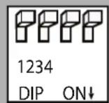
SET RADIO DIPSWITCHES TO THE ON POSITION
| Alpine JV | C Kenwood Clarion Pioneer/Other Sony Fusion | ||||
| 1 2 1 & | 2 3 1, 2, & 3 | 4 | 1 & 4 | ||
Steering Wheel Controls (cont.)
Optional SWC Programming Procedure
- Turn the key to the ignition position.
- Press and release programming button on the side of the interface. The Status LED will turn green.
- Within 7 seconds, press the button that is to be learned on the steering wheel. The LED will turn red when the button is pressed. At this point you have two options:
A. For short press functionality: Release the button within 1.5 seconds. The LED will turn back on.
B. For long press functionality: Hold the button until the LED starts blinking. Release the button and the LED will go back to solid.
-
If you need to program more buttons, repeat step 3 for each additional audio function on the steering wheel.
-
If you come across a function in the chart that your steering wheel does not have, or you do not want to program, press and release the program button on the side of the interface to skip that function.
-
Once programming is completed, wait seven seconds. The LED will flash three times indicating end of programming.
-
Test the interface for proper functionality. Whenever a SWC is pressed the LED on the interface should blink. If any function does not work, repeat the programming steps.
Optional Programming Order
| Alpine JVC Henwood Clarion Other * Pioneer Sony Fusion | ||||||||
| 1 Volume + Volume + Volume + Volume + Volume + Volume + Volume + | ||||||||
| 2 | Volume - | Volume - | Volume - | Volume - | Volume - | Volume - | Volume - | Volume - |
| 3 | Mute | Mute | ATT | Mute | Mute | Mute | Mute | Mute |
| 4 | Preset + | Source | Source | Source | Preset + | Preset + | Preset + | Source |
| 5 | Preset - | Track + | Play | Search + | Preset - | Preset - | Preset - | Track + |
| 6 | Source | Track - | Track + | Search - | Source | Source | Source / End Call | Track - |
| 7 | Track + | Band / Disc + | Track - | Band | Track + | Track + | Track + | Audio |
| 8 | Track - | Preset / Disc - | Disc / FM + | Send / End | Track - | Track - | Track - | Power |
| 9 | Power | Select | Disc / AM - | Send | Band | Band | Band | |
| 10 | Enter / Play | Attenuation | Answer | End | Answer ** | Phone Menu | Power / End Call | |
| 11 | Band / Program | Phone Receive | Voice | Voice | End** Answer Call Voice / Answer / End Call | |||
| 12 | hong@ One | *PT | C#E | Voice (Android Auto & Car Play)Answer / End Call *** | |||||
| 13 | Ed | Voice | o#F | Voice | ||||
| 14 | Voice | Power | Mute | |||||
| 15 | et#P | |||||||
| * Advent, Boyo, Dual, Lightning Audio, Jensen, Rockford Fosgate & Visteon ** Jensen & Advent ONLY *** XAV-AX100 Only | ||||||||
Steering Wheel Control Re-Calibration
SWC re-calibration is necessary when the SWC operation in vehicles with analog SWC is erratic or non-existent. This process re-calibrates the SWC values to the RP4 interface so it will know what they can be set to for button function assignment. The interface must be programmed in the specific order shown in the chart on the next page. If you come across a function in the chart that your steering wheel does not have you must press and release the program button on the side of the interface to skip that function. The LED will flash off and on confirming that you have successfully skipped that function and are ready to proceed to the next one.
The SWC and radio command assignments can always be restored to default values by entering re-calibration mode (Steps 1-2) and not pressing any buttons. After 7 seconds the re-calibration mode will time out and all default values will be restored.
Steering Wheel Controls (cont.)
SWC Re-Calibration Procedure
- Turn the key to the ignition position.
- Press and hold the programming button until the LED begins blinking amber. When the LED begins blinking, release the programming button. The LED will light solid amber. PLEASE NOTE: If the vehicle has CAN-Bus SWC the LED will never blink amber and will go directly to blinking red.
- Within 7 seconds, press and hold the button that is to be learned on the steering wheel. The LED will turn off when the button is pressed and begin blinking when the value has been learned. Once the LED begins blinking, release the button.
- If you need to program more buttons, repeat step 3 for each additional audio function on the steering wheel.
- If you come across a function in the chart that your steering wheel does not have, press and release the program button on the side of the interface to skip that function.
- Once programming is completed, wait seven seconds. The LED will flash indicating end of programming.
- Test the interface for proper functionality. Whenever a SWC is pressed the LED on the interface should blink. If any function does not work, repeat the programming steps.
| Button Programming Order |
| Volume Up |
| Volume Down |
| Track Up |
| Track Down |
| Mode |
| Mute |
| Voice |
| End Call |
| Answer Call |
| Power |
After you have re-calibrated the SWC buttons, the default SWC button assignments will be the same as what is listed in the chart on page 3. If you wish to re-assign button functions you must also go through the programming process on page 4.
Testing & Verification
- Turn the ignition on. The LED on the interface will turn on & the +12v accessory wire will turn on.
- Turn on the radio & check balance & fade. Note: Factory amplified Systems must use the Radio PRO App to adjust amplifier settings. Verify that the factory subwoofer (if present) is playing.
- Verify that all SWC are functioning properly.
- Verify that the programmable 12v+ output is functioning as intended.
- The LED & radio will turn off when the ignition is turned off.
Restoring Factory Settings
You can restore the interface to factory default settings by pressing and holding the programming button on the side of the module until the status LED starts blinking red. Once the LED starts blinking red, release the button. You must release the button while the LED is blinking red in order to perform the reset.
This reset will restore the following settings to their factory defaults:
- SWC Mapping
- SWC Calibration
• Programmable 12v+ Output (Latched)
• Factory Amplifier Settings
RadioPRO App
Use of the RadioPRO App in Hyundai allows you to do the following:
- Configure User Interface Options such as:
• Red/White wire output behavior
Factory amplifier settings (Bass, Mid, Treble, Gain, Fader & Balance) - Update Product Firmware
- Read Firmware/Hardware Versions
- Access Product User Manuals
Programmable Red/White Wire
The red/white wire can be programmed to do a pulsed or latched trigger that is controlled by a user assigned steering wheel control button. Select User Interface Options then set the behavior of the red/white wire using the drop down menu. PLEASE NOTE: Available triggers depend on what info is available on the vehicles data bus. Restoring factory settings on the module will default this wires output back to a latched SWC trigger.
Latched - This selection will provide a latched 12v+ output that can be tied to any of the vehicles SWC. This means that when you press the assigned SWC, the red/white wire will turn on and remain on until the assigned SWC is pressed again or the ignition is turned off.
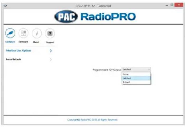
Pulsed - This selection will provide a user programmable timed 12v+ output that can be tied to any of the vehicles SWC. This means that when you press the assigned SWC, the red/white wire will pulse for the pre-programmed user time. The range for pulse time is 100 milliseconds - 25.5 seconds (.1-25.5).

Factory Amplifier Settings
The RadioPRO app will also allow you to adjust the settings of the factory amplifier. You can adjust Amp Gain, Fader, Balance, Bass, Mid & Treble. Restoring factory settings on the module will default all values back to middle.
Firmware Updates
The RadioPRO app will also allow you to update the interface with new firmware as it becomes available. Please visit www.pac-audio.com or contact our tech support department to see if there is a firmware update for your interface.


- INTRODUCTION & FEATURES
- IMPORTANT NOTES
- WIRING CONNECTION CHART
- INSTALLATION STEPS
- STEERING WHEEL CONTROLS
- DEFAULT STEERING WHEEL CONTROL PROGRAMMING
- STEERING WHEEL CONTROLS (CONT.)
- OPTIONAL STEERING WHEEL CONTROL PROGRAMMING
- SHORT PRESS LONG PRESS DUAL COMMAND FUNCTIONALITY
- PROGRAMMABLE 12V OUTPUT
- OPTIONAL SWC PROGRAMMING PROCEDURE
- STEERING WHEEL CONTROL RE-CALIBRATION
- SWC RE-CALIBRATION PROCEDURE
- TESTING & VERIFICATION
- RESTORING FACTORY SETTINGS
- RADIOPRO APP
- USE OF THE RADIOPRO APP IN HYUNDAI ALLOWS YOU TO DO THE FOLLOWING
- PROGRAMMABLE RED/WHITE WIRE
- FACTORY AMPLIFIER SETTINGS
- FIRMWARE UPDATES
Brand : PAC
Model : RP4.2-HY12
Category : Car audio interface