
Imperium Go Plus SD 9161 - Vacuum Cleaner Arçelik - Free user manual and instructions
Find the device manual for free Imperium Go Plus SD 9161 Arçelik in PDF.


| Product Type | Cordless Stick Vacuum Cleaner |
| Brand | Arçelik |
| Model | Imperium Go Plus SD 9161 |
| Nominal Input Power | 550 W |
| Input Voltage | 100-240 V~ 50-60 Hz 0.8 A (max.) |
| Output Voltage | 36 V — 0.6 A |
| Charging Time | 4-5 hours |
| Runtime (Min Speed) | Up to 60 min on hard floor, 30 min on carpet, 90 min handheld |
| Runtime (Medium Speed) | Up to 30 min on hard floor, 15 min on carpet, 30 min handheld |
| Runtime (Max Speed) | Up to 15 min on hard floor, 7 min on carpet, 8 min handheld |
| Battery Type | ZB 2007 (removable Li-ion) |
| Floor Detection | Automatic (electric turbo brush detects floor type) |
| Accessories Included | Electric turbo brush, charging dock, tube, support, hard floor roll, elbow, narrow mouth nozzle, mini turbo brush, dust brush |
| Filter System | Metal filter, inlet foam, EPA E12 filter, outlet foam |
| Display | LCD with battery %, remaining time, speed level, color indicator |
| Wand Type | Foldable wand with release button |
| Warranty | 12 months (terms apply) |
| Safety Certifications | Complies with international safety standards, WEEE directive |
Frequently Asked Questions - Imperium Go Plus SD 9161 Arçelik
User questions about Imperium Go Plus SD 9161 Arçelik
0 question about this device. Answer the ones you know or ask your own.
Ask a new question about this device
Download the instructions for your Vacuum Cleaner in PDF format for free! Find your manual Imperium Go Plus SD 9161 - Arçelik and take your electronic device back in hand. On this page are published all the documents necessary for the use of your device. Imperium Go Plus SD 9161 by Arçelik.
USER MANUAL Imperium Go Plus SD 9161 Arçelik
natural_image
Abstract geometric pattern composed of interlocking black lines on white background (no text or symbols)
natural_image
Simple line drawing of a decorative border with circular motifs (no text or symbols)SD 9161
TR - EN - RU - AR
Dongguan Yinli Electronics Co., Ltd
Model Kimliği : YLS0241A-E360060
natural_image
Technical line drawing of a mechanical device with arrows indicating motion or assembly (no text or symbols)natural_image
Diagram showing a mechanical component being inserted into a housing, with arrows indicating direction (no text or symbols present)natural_image
Technical line drawing of a vacuum cleaner with a magnified inset showing internal components (no text or symbols)natural_image
Technical line drawing of a vacuum cleaner with a mounted device and base mount (no text or symbols)natural_image
Circular icon with battery and 0% symbol, no text or numbers presentnatural_image
Line drawing of a vacuum cleaner with attached circuit components (no text or symbols)natural_image
Diagram of a vacuum cleaner with attached device, showing internal components and a close-up view (no text or symbols)natural_image
Icon of a ceiling light bulb inside a yellow circular frame (no text or symbols)natural_image
Circular icon with battery and 0% symbol, no readable text or numbersnatural_image
Circular icon with a white chimney and ruler symbol on dark background, no text or numbers present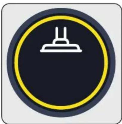
natural_image
Circular warning sign with a white electrical plug symbol on a dark background, enclosed in a yellow ring (no text or numbers)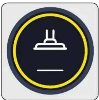
natural_image
Circular icon with a white chimney and horizontal line, no text or symbols present.natural_image
Diagram of a hand tool assembly with arrows indicating process steps (no text or labels)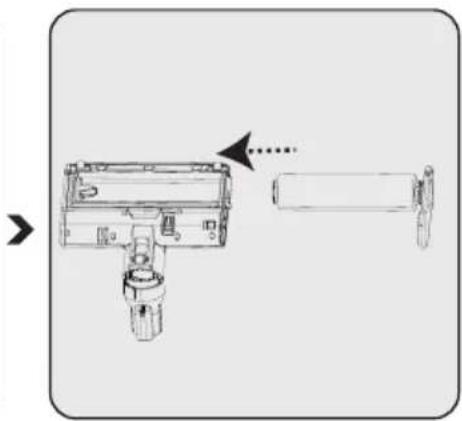
natural_image
Diagram of a mechanical device with a cylindrical component and a separate cylindrical component, showing no text or symbols.natural_image
Illustration of a hand cleaning a mechanical device with a cloth (no text or symbols)natural_image
Illustration of a manual blender being poured into a container (no text or symbols)natural_image
Technical illustration of mechanical components with numbered parts (1 and 2), no visible text or symbolsnatural_image
Mechanical component diagram showing a rotating shaft and housing with directional arrows indicating motion (no text or symbols)natural_image
Diagram showing four cylindrical containers arranged in a cross pattern with an upward arrow, no text or symbols present.natural_image
Diagram showing a cylindrical container being dropped with a downward arrow, no text or symbols presentnatural_image
Mechanical assembly diagram showing a rotating component with directional arrows indicating motion (no text or symbols)natural_image
Technical line drawing of a mechanical component with three views (top, front, side), no text or symbols present.natural_image
Mechanical component diagram showing a rotating shaft and housing with directional arrows indicating motion (no text or symbols)natural_image
Diagram of two cylindrical objects with a handle and an upward arrow, no text or symbols presentnatural_image
Three line drawings of containers: a cylindrical container, a lid with handle, and a tray with seeds (no text or symbols)natural_image
Diagram showing two mechanical components with a downward arrow indicating motion (no text or symbols)natural_image
Mechanical component diagram showing a rotating assembly with labeled parts 1 and 2 (no text or symbols beyond labels)natural_image
Mechanical assembly diagram showing a motor with rotational motion arrows (no text or labels)natural_image
Diagram of two cylindrical mechanical components with an upward arrow indicating motion or assembly (no text or symbols)natural_image
Three line drawings of containers: a cylindrical container, a cylindrical container with lid, and a container with seeds or seeds emerging from its surface (no text or symbols)natural_image
Diagram showing two mechanical components with a downward arrow indicating motion or change (no text or symbols)natural_image
Mechanical assembly diagram showing a rotating motor with labeled parts 1 and 2 (no text or symbols beyond labels)natural_image
Illustration of two mechanical components with arrows indicating motion, no text or symbols presentnatural_image
Illustration of three abstract 3D shapes: a curved structure, a semi-circular shape, and a bowl with granular material (no text or symbols)natural_image
Three mechanical component cutouts with an arrow indicating direction (no text or symbols)natural_image
Technical line drawing of a vacuum cleaner with a clamping device (no text or symbols)natural_image
Technical line drawing of a mechanical component with an inset magnified view showing a detail (no text or symbols)natural_image
Technical line drawing of a mechanical device with a directional arrow indicating motion (no text or symbols present)natural_image
Abstract line drawing of a stylized object above a wavy rectangular frame (no text or symbols)natural_image
Technical line drawing of a mechanical device with no visible text or symbolsnatural_image
Technical line drawing of a mechanical device with an arrow indicating transformation or assembly (no text or symbols present)natural_image
Technical line drawing of a mechanical device with two shafts and housing (no text or symbols)natural_image
Diagram showing eye detection mechanism with two views of a device (no text or symbols present)natural_image
Diagram showing a human eye with a vertical line and a small object inside, no text or symbols presentnatural_image
Line drawing of a stylized eye with a camera and lens, no text or symbols presentnatural_image
Technical line drawing of a mechanical device with housing and base plate (no text or symbols)- https://www.instagram.com/arcelik/
- https://twitter.com/arcelik
- https://www.facebook.com/arcelik/
- https://www.youtube.com/user/tvarcelik
* Posta Adresimiz:
Please read this guide first!
Dear Customer,
Thank you for choosing a BEKO product. We would like you to achieve the optimal efficiency from this high quality product which has been manufactured with state of the art technology. Please make sure you read and understand this guide and supplementary documentation fully before use and keep it as a reference. Include this guide with the unit if you hand it over to someone else. Observe all warnings and information herein and follow the instructions.
Symbols and their meanings
These symbols are used throughout this guide:

Important information and recommendations regarding the use of the appliance.

CAUTION: Warnings on personal injury or property damage.

Protection class against electric shock.
1 Important safety and environmental instructions
This section includes the safety instructions necessary to prevent the risk of personal injury or material damage.
Failure to observe these instructions will void any and all warranties.
1.1 General safety
- The device complies with international safety standards. - This appliance is intended to be used in household and similar applications such as:
- Staff kitchen areas in shops, offices and other working environments;
- Farm houses;
- By clients in hotels, motels and other residential type environments;
- Bed and Breakfast environments;
- It is not fit for industrial use.
- This device can be used by children over 8 years of age, people with physical, sensory or mental challenges or people with lack of experience or knowledge; as long as control is ensured or information is provided regarding the hazards. Children must not play with the appliance. Cleaning and user maintenance shall not be carried out by unattended children.
- Do not use the appliance if the power cord or the appliance is damaged. Contact authorized service.
- Your mains power supply shall be in align with the specified information on the type tag.
- Do not use the appliance with an extension cord.
• To prevent the power cord get damaged, make sure that it does not get stuck, bent or contact with sharp edges.
- Do not touch the plug of the appliance with damp or wet hands while the appliance is plugged in.
1 Important safety and environmental instructions
- Do not pull on the cord while unplugging the appliance.
- Do not vacuum flammable materials and ensure that the cigarette ashes are cooled down before vacuuming them.
- Do not vacuum water and other fluids.
- Protect the appliance against precipitation, humidity and heat sources.
- Do not use the appliance near or on explosive or flammable environments or materials.
- Unplug the appliance before cleaning and maintenance.
- Do not immerse the appliance or its power cord in water for cleaning.
- Do not disassemble the appliance.
- Only use the authentic parts or the manufacturer's recommended parts.
-
To prevent blockage of the filter or damage to the motor, do not vacuum cement, plaster or fragments of compressed paper.
-
Use the appliance with the adapter delivered with the appliance only.
- Do not use the appliance without filters, it may get damaged.
- Keep packaging materials away from the reach of children.
- This appliance is not intended to be used by persons, including children, with physical, sensory and mental disabilities or those who have not adequate experience and knowledge regarding its use, unless they are under the supervision of a person responsible for their safety or they are informed about the operation of the appliance.
- The children shall be supervised to prevent them from playing with the appliance.
- Unplug the adaptor and remove the battery pack before any cleaning or maintenance procedure.
1 Important safety and environmental instructions
- To avoid any risk of hazard, a damaged adaptor shall be replaced by the manufacturer, the authorized representative of the manufacturer or a similarly qualified technician.
- Keep your fingers, hair and loose clothes away from moving parts or clearances while vacuuming.
- Batteries shall be removed from the appliance before discarding the appliance.
- Disconnect the appliance from power supply before removing the battery.
- Please discard used batteries in accordance with local laws and regulations.
- The batteries included in this appliance may only be replaced with qualified persons.
- CAUTION: Use the YLS0241A-A360060 removable supply unit delivered with the appliance to charge to the battery.
- Please install/remove batteries as per the instructions specified in the user guide.
- Do not use batteries of different types or old and new batteries together.
- Batteries shall be installed with the correct polar layout.
- Remove the depleted batteries from the appliance and dispose of these batteries in a safe way.
- If you do not intend to use the appliance for a long while, the batteries shall be removed.
- Fluid may leak from batteries damaged as a result of incorrect operation. Do not contact this fluid. Discard damaged batteries as per the laws and legislation and contact the authorized service.
- Do not short circuit the supply terminals.
- Use with ZB 2007 batteries only.
1 Important safety and environmental instructions
- This appliance shall not be operated by children and people with limited physical, sensory and cognitive skills or people with lack of experience and knowledge unless they are under supervision or they are provided with the relevant instructions.
- The children shall be supervised to prevent them from playing with the appliance.
1.2 Compliance with the WEEE Directive and disposal of the waste product
This product complies with EU WEEE Directive (2012/19/EU). This product bears a classification symbol for waste electrical and electronic equipment (WEEE).
This symbol indicates that this product shall not be disposed with other household wastes at the end of its service life. Used device must be returned to official collection point for recycling of electrical and electronic devices. To find these collection systems please contact to your local authorities or retailer where the product was purchased. Each household performs important role in recovering and recycling of old appliance. Appropriate disposal of used appliance helps prevent potential negative consequences for the environment and human health.
1.3 Packaging information

The product's packaging is made of recyclable materials, in accordance with the National Legislation.
Do not dispose the packaging waste with the household waste or other wastes, dispose it to the packaging collection areas specified by local authorities.
1.4 Waste batteries
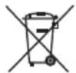
Ensure that the waste batteries are disposed of in accordance with local laws and regulations. The symbol on the battery and packaging indicates that the battery delivered with the product should not be considered as household waste. This symbol may be used in combination with a chemical symbol in some regions. If the batteries contain more than 0.0005 % mercury and more than 0.004 % of lead, the Hg chemical is added for mercury and the Pb chemical symbol is added for lead under the symbol. By ensuring that the batteries are disposed correctly, you shall contribute to the prevention of potential damage to the environment and human health due to improper disposal of the batteries.
1.5 Actions to be taken for energy saving
- To avoid redundant energy consumption while using the device, set the speed levels according to the floor you are sweeping.
- Under normal conditions, low speeds are used to clean the hard floors, curtains and sofas, and high speeds are used to clean the carpets.
2 Overview
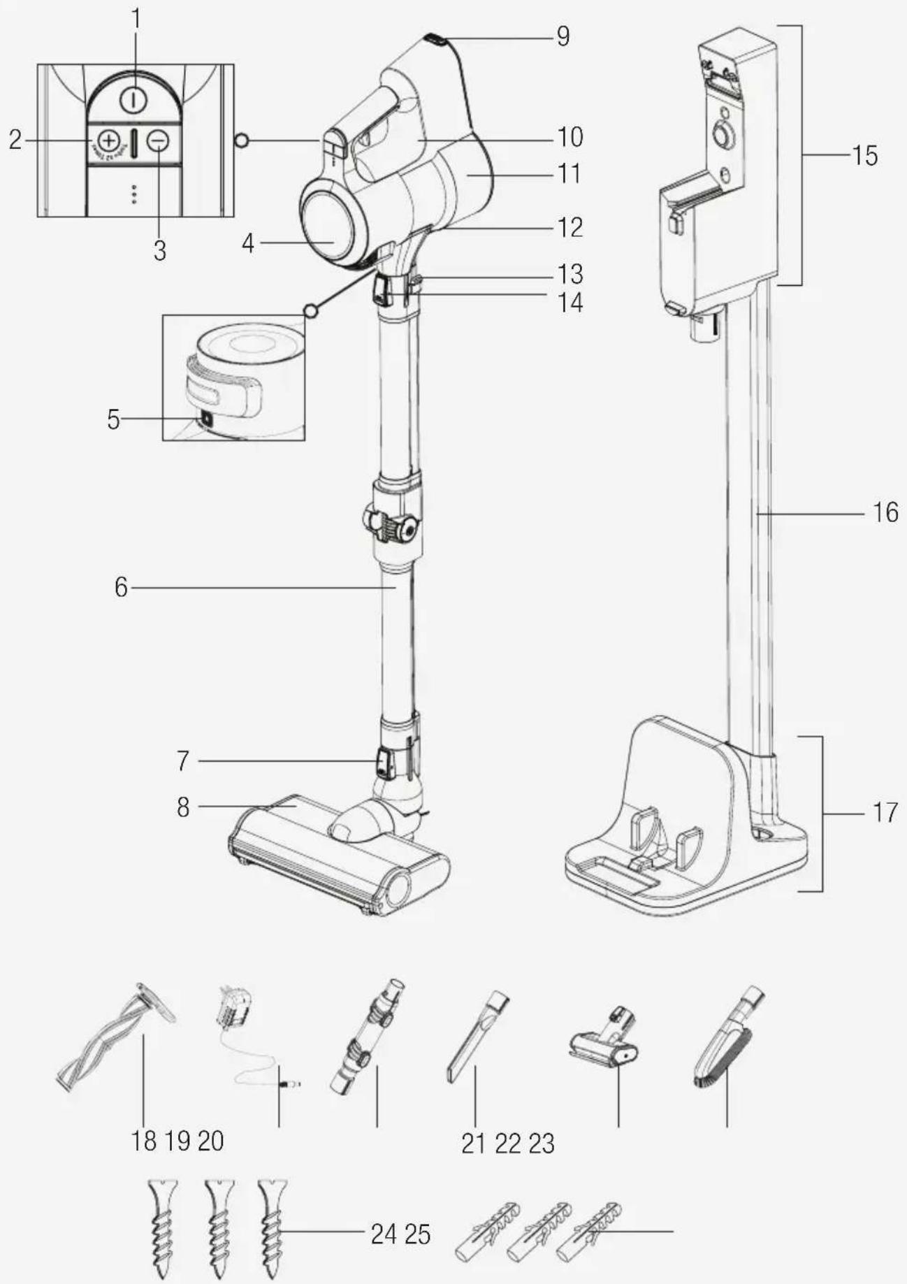
2.1 Controls and components
- On-Off switch
- Mode button +
- Mode button -
- LCD Display
- Filter cover release button
- Foldable wand
- Brush release button
- Electric turbo brush
- Battery pack release button
- Appliance body
- Dust container
- Dust reservoir lid opening button
- Foldable wand button
- Wand release button
- Charging dock
- Charging dock tube
- Charging dock support
- Hard floor roll
- Charge adaptor
- Elbow
- Narrow mouth nozzle
- Mini turbo brush
- Dust brush
- Screw
- Dowel
2.2 Technical data
Nominal input power: 550 W
Input: 100 - 240 V\~ 50-60 Hz 0.8 A (max.)
Output: 36 V — 0.6 A
Charging period: 4-5 hours
Operation period under maximum power: up to 15 min.
Operation period under medium power: up to 30 min.
Operation period under minimum power: up to 60 min.
The rights to make technical and design changes are reserved.
The values provided with the appliance or its accompanying documents are laboratory readings in accordance with the respective standards. These values may differ depending on the use and ambient conditions.
2 Overview
| Intended Use Speed rating Operating period | |||
| Hard floor | Minimum speed | Up to 60 min. | 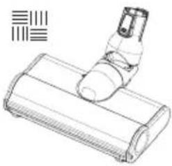 |
| Medium speed | Up to 30 min. | ||
| Maximum speed | Up to 15 min. | ||
| Carpet floor | Minimum speed | Up to 30 min. | 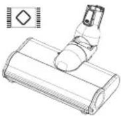 |
| Medium speed | Up to 15 min. | ||
| Maximum speed | Up to 7 min. | ||
| Hand-held type | Minimum speed | Up to 90 min. | 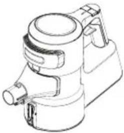 |
| Medium speed | Up to 30 min. | ||
| Maximum speed | Up to 8 min. | ||

The operating periods specified above are valid under full charge (100%).

Electric turbo brush (8) detects the floor automatically. Operating periods may vary as per switching between floor types during operation.

Operating periods for hand-held type are valid for operation with no accessories, and operation with an elbow (20), with a dust brush (23) and with the narrow mouth nozzle (21). Period varies in case of operation with mini turbo brush (22).
3 Installation
3.1 Intended use
This appliance is intended for household use and it is not suitable for industrial use.
3.2 Installation of the mobile charging dock
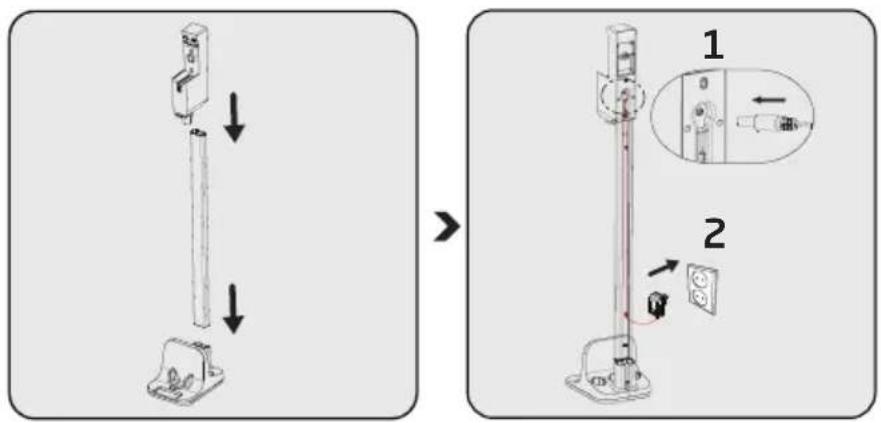
Install charging dock tube (16) to the charging dock support (17), then install the charging dock (15) to the charging dock tube (16).
Install the thin end of the charger to the seat on the charging dock (15). Plug the charging adaptor (19) to the outlet.
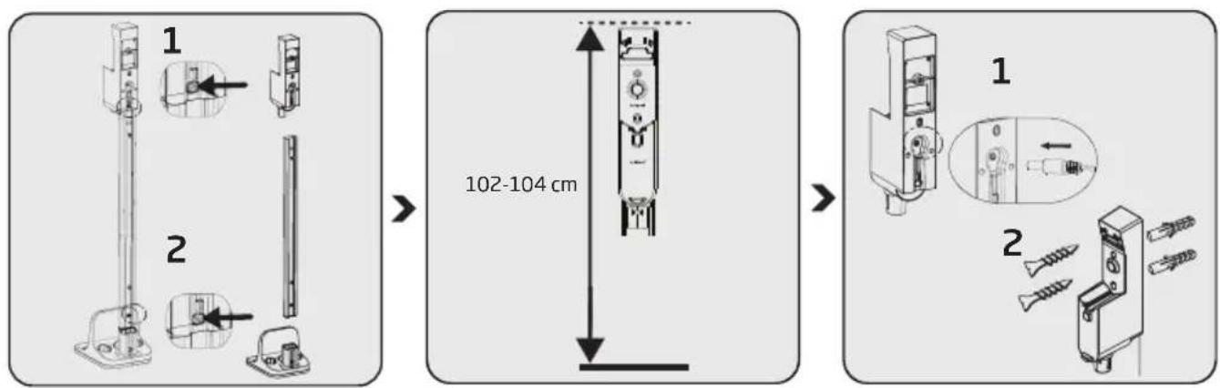
If you want to install the charging dock (15) to the wall, detach the charging unit from the tube (16) and support (17) using two separate buttons.
Position the charging dock (15) at a height of 102-104 cm from the ground.
Install the end of the charging adaptor (19) to the seat on the back of the charging dock (15).
Put the cord of the charging adaptor through the power cord securing ring behind the charging dock tube and secure the cord.
Install the charging dock (15) to the wall using two screws (24) and two dowels (25).
3 Installation
3.3 Installation of the body and the brush
natural_image
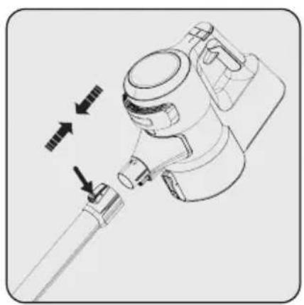
Technical line drawing of a mechanical device with arrows indicating motion or assembly (no text or symbols)Install the wand to the end of the body (10).
Remove it by pressing the release button (14).
natural_image
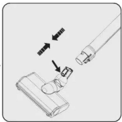
Diagram showing a mechanical component with arrows indicating motion or assembly (no text or symbols)Press the electric turbo brush release button (7) on the electric turbo brush (8) and push it in the direction of arrow towards the wand.
natural_image
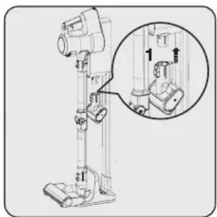
Technical line drawing of a vacuum cleaner with a magnified inset showing internal components (no text or symbols)Install the mini turbo brush (22) to the charging dock (15).
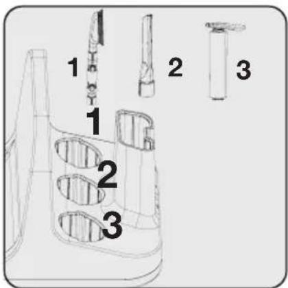
Place other accessories to the charging dock support (17).
4 Operation
4.1 Charging the appliance
natural_image
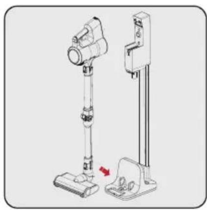
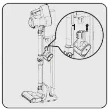
Technical line drawing of a vacuum cleaner with a mounted device and base mount (no text or symbols)Secure the electric turbo brush (8) to the charging dock support.
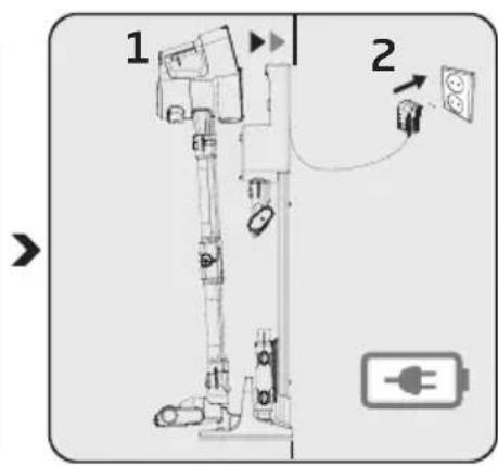
Install the body (10) to the charging dock (15).
Plug the charging adaptor (19) to the outlet.
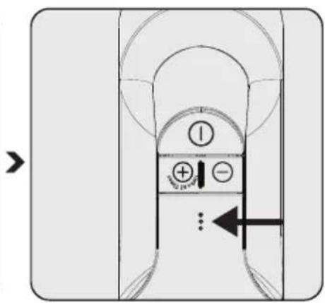
Flashing of the charge indicator LEDs in white colour indicates that the appliance is being charged. — When all levels of the charge indicator LEDs are illuminated, this indicates that the charging of the appliance is completed.

It takes up to 5 hours to charge the appliance completely. The appliance shall not be operated while charging.
natural_image
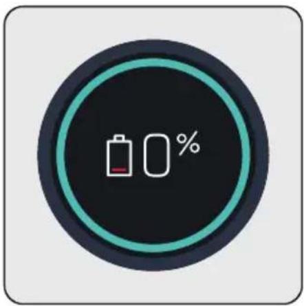
Circular icon with battery and 0% symbol, no readable text or numbersWhen you place appliance to the charging dock (15), it starts to charge and the battery charge percentage shall be displayed on the screen (4). Percentage (%) and battery charge indicator are increased as the appliance is charged. The circle around the screen is illuminated in blue and as moving around.
 | The screen (4) darkens 3 minutes after connecting the appliance to the charging dock and the battery status is displayed by 3 LEDs on the appliance.To see the charge percentage of the appliance, press + (2) or - (3) mode button once while it is charging. |
4 Operation
4.2 Operation

It may be connected for charging before the complete discharging of the battery. The appliance may be kept continuously on the charging dock (15) until the next operation.
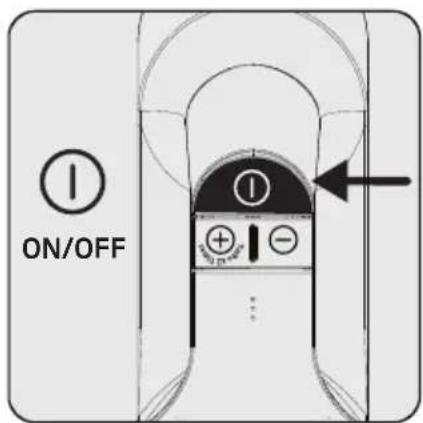
Press the on/off button (1) to operate the appliance. The appliance starts operating with the minimum speed when the on/off button is pressed.

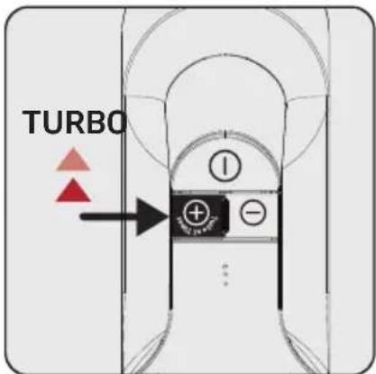
Press the “+” mode button (2) once to operate the appliance with medium speed. Press once more to operate it with the maximum speed.

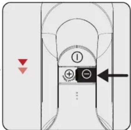
Press the “-” mode button (3) once to switch to a lower speed while operating at maximum speed or medium speed.
natural_image
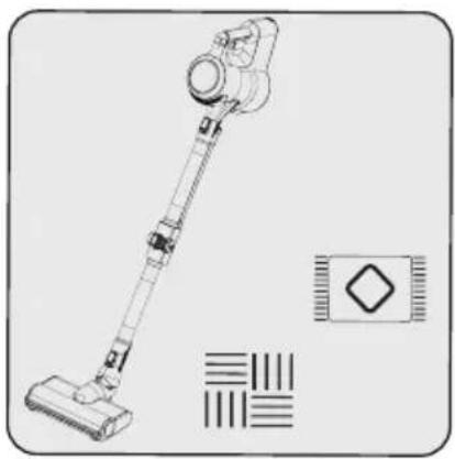
Line drawing of a vacuum cleaner with attached circuit board (no text or symbols)This appliance is suitable for use on carpets and hard floors.

natural_image
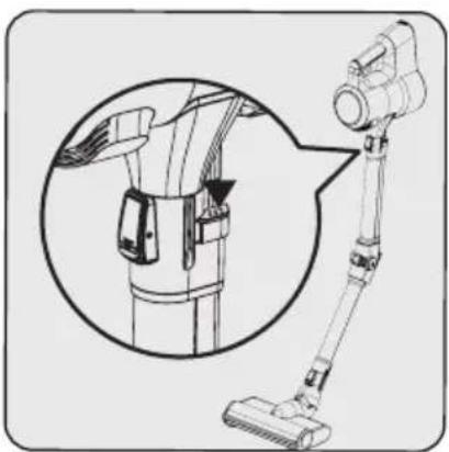
Diagram of a vacuum cleaner with attached device, showing internal components and part outline (no text or symbols)Press one of the two buttons (13) on the wand to fold the wand. Thus, you may reach hard-to-reach areas such as the areas under the seats.

If the adaptor on the charging is plugged to the outlet, the appliance stops operating automatically if it is placed on the charging dock (15) while it is being operated.
4.3 LCD Display
4.3.1 Main Screen
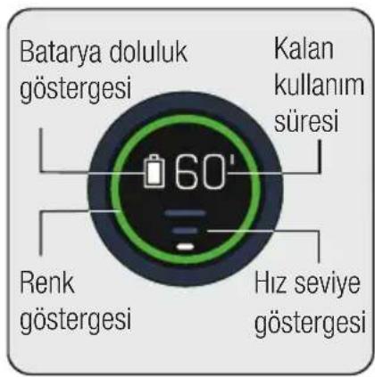
Battery charge indicator: Varies as per the remaining operating period.
Remaining operating period:
Indicates the remaining charge level in minutes as per the speed level and floor type used.
Colour indicator: Indicates your remaining operating period as green, yellow and red.
Speed level indicator: Indicates the speed level that the appliance is being used.
For example, all three bar indicators are illuminated in white while using the appliance at maximum speed.
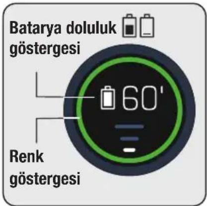
The circle around the display (4) changes colour as per the remaining operating period.
Simultaneously, the battery charge indicator changes as per the remaining operating period.
Colour indicator:
Low speed level
- Illuminates in green between 60 minutes and 30 minutes at full charge.
- Illuminates in yellow in the last 30 minutes to 3 minutes.
- Illuminates in red in the last 3 minutes of remaining charge.
Medium speed level
- Illuminates in yellow between 30 minutes and 3 minutes at full charge.
- Illuminates in red in the last 3 minutes of remaining charge.
Maximum speed level
- Illuminates in yellow between 7 minutes and 3 minutes at full charge.
- Illuminates in red in the last 3 minutes of remaining charge.

The remaining operating period, battery charge indicator and colour indicator displayed on the screen (4) vary as per the speed level and floor type used.
4 Operation
4.3.2 Changing the speed
natural_image
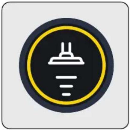
Icon of a ceiling light bulb inside a yellow circular frame (no text or symbols)When the speed level is changed a moving brush symbol and the speed level indicator shall be displayed on the screen. Then, the main screen shall be displayed.
4.3.3 Charging
natural_image
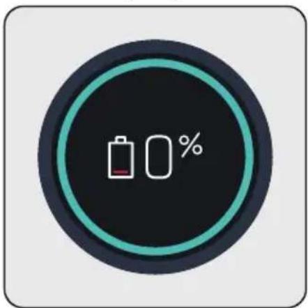
Circular icon with battery and 0% symbol, no text or numbers presentWhen you place the appliance to the charging dock (15), it starts to charge and the battery charge percentage shall be displayed on the screen (4). Percentage (%) and battery charge indicator are increased as the appliance is charged. The circle around the screen is illuminated in blue and as moving around.

The screen darkens 3 minutes after connecting the appliance to the charging dock (3) and the battery status is displayed by 3 LEDs on the appliance.
To see the charge percentage of the appliance, press + or - mode button once while it is charging.
4.3.4 Automatic floor detection
natural_image
Circular icon with a white electrical plug symbol above a ruler, no text or numbers present.
natural_image
Circular traffic sign with a white chimney icon on a dark background, enclosed in a yellow ring (no text or symbols)
natural_image
Circular icon with a white chimney and horizontal line, no text or symbols present.4 Operation
When the auto floor detecting brush (8) moves from a carpet floor to a hard floor, the figures shown above shall be animated on the screen (4).
natural_image
Circular icon with a white chimney symbol on a dark background, enclosed in a yellow ring (no text or numbers)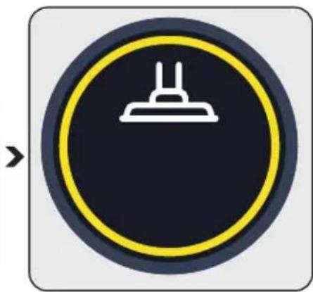
natural_image
Circular icon with a white electrical plug symbol on a dark background, enclosed in a yellow ring (no text or numbers)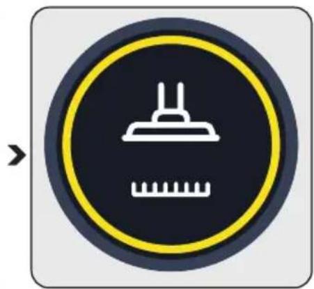
natural_image
Circular icon with a white chimney and ruler symbol on dark background, no text or numbers presentWhen the auto floor detecting brush (8) moves from a hard floor to a carpet floor, the figures shown above shall be animated on the screen (4).
4.3.5 Warning screens
4.3.5.1 Filter cleaning warning
natural_image
Circular icon with a red warning sign and an exclamation mark on a black background (no text or symbols)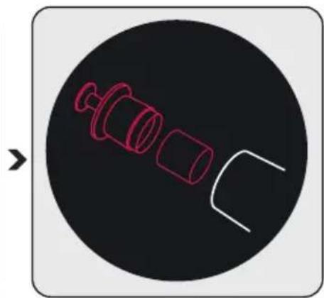
natural_image
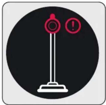
Diagram of a mechanical component with three cylindrical parts and a curved cutout, enclosed in a black circle (no text or symbols)The filters shall be cleaned regularly to prevent loss of performance. When it is not cleaned regularly (in case of excessive dust), a filter cleaning animation is displayed on the screen for a very short period of time to indicate that the metal filter and inlet foam shall be cleaned. However, the appliance continues to operate.

It is recommended to clean the metal filter and the inlet foam as described in Section "5.2 Cleaning of the metal filter and inlet foam" before continuing with the cleaning.
4.3.5.2 Brush blockage warning

When the turbo brush is blocked or too many hair, etc. materials are tangled on the rotating roll, the animation indicating the brush blockage warning is displayed on the screen continuously and the appliance stops operating.

It is recommended to clean the brush as described in Section “5.4 Cleaning of the brush” before continuing with the cleaning. Remove the turbo brush (8) from the foldable wand (6). Inspect the turbo brush to the wand connection and remove any blockages.
4.3.5.3 Vacuum duct blockage warning

When the vacuum duct is blocked, the animation indicating that the duct is blocked is displayed on the screen continuously and the appliance stops operating. Determine the reason of the blockage of the vacuum duct.

It is recommended to determine the reason of blockage as described in Section “5.5 Cleaning of the blockages” before continuing with the cleaning. Remove the turbo brush (8) from the foldable wand (6). Remove the foldable wand from the body of the appliance. Inspect the turbo brush to the wand connection and remove any blockages. Inspect the wand from the inlet and outlet ends of the foldable wand, and remove any blockages. Inspect the vacuum nozzle of the appliance body (10) and remove any blockages.
4 Operation
4.4 Accessories
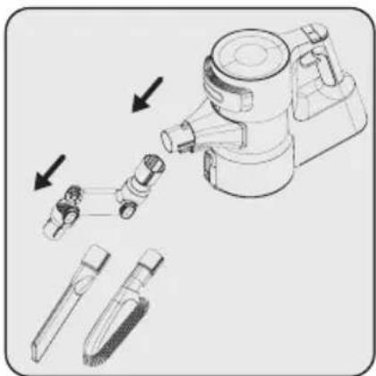
You may use the accessories by installing them to the end of the body.
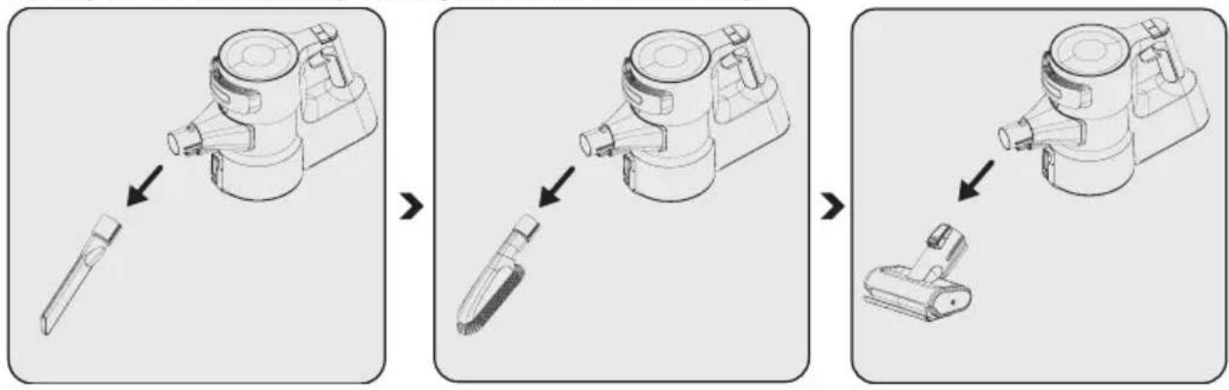
Narrow mouth nozzle (21):
Suitable for vacuuming the rear of the furnitures, hard to reach areas and narrow areas.
Dust brush (23): Suitable for vacuuming curtains, waxed furniture and delicate and fragile objects.
Mini turbo brush (22): Suitable for vacuuming floorings, stair steps, car interiors, sofas and seat, etc. It is also used for vacuuming pet hair on such surfaces.
natural_image
Technical illustration of a vacuum cleaner assembly with exploded view (no text or symbols)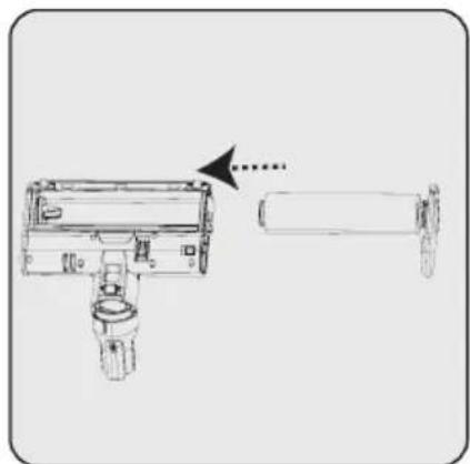
natural_image
Technical line drawing of a mechanical device with an arrow indicating transformation or assembly (no text or symbols present)You may use the elbow (20) by installing it to the end of the body (10) to access hard to reach places.
This accessory is suitable for use on delicate hard floors (natural hardwood, etc.).
5 Cleaning and maintenance
Turn off and unplug the appliance before cleaning.

CAUTION: Do not use benzene, solvents, abrasive cleaners, metal objects or hard brushes to clean the appliance.

CAUTION: Deformation may occur on the filters within time as a result of usage. It shall be replaced with a new one to prevent loss of performance. Contact with the customer services to buy a new one. (see P. 25)
5.1 Cleaning of the dust reservoir

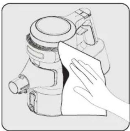
We recommend you to clean the dust reservoir (11) after each operation.
natural_image
Illustration of a hand cleaning a mechanical device with a cloth (no text or symbols)Wipe the surface of the body with a wet cloth (10).
natural_image
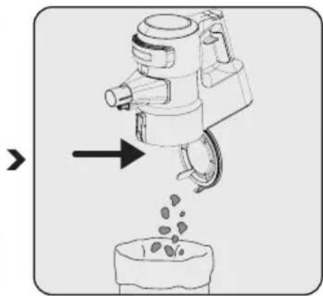
Illustration of a hand pouring liquid into a container (no text or symbols)Press the dust reservoir lid opening button (12) to open the dust reservoir (11) and discharge the dust collected inside.
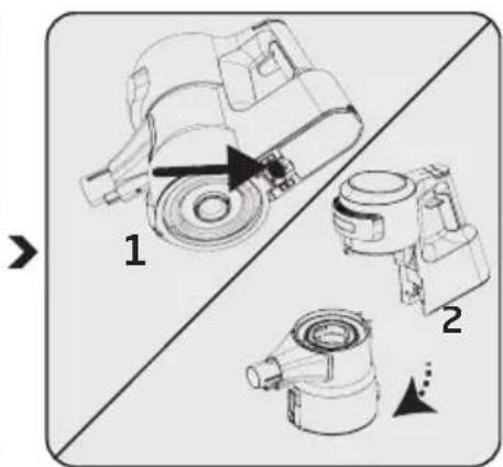
Push the trigger under the appliance to clean the dust reservoir (11).
Detach the dust reservoir (11) from the body (10).
5 Cleaning and maintenance
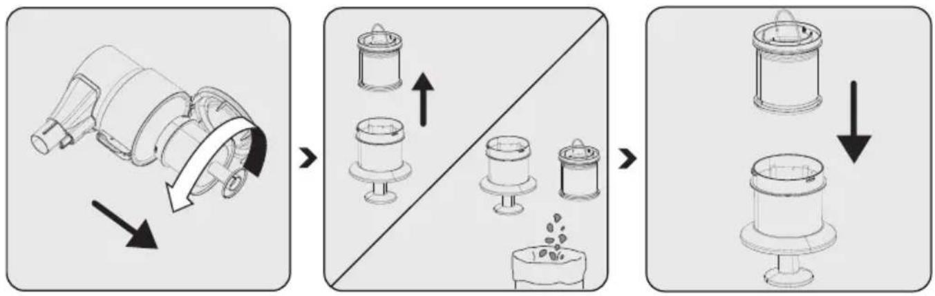
Remove the metal filter and inlet foam inside the dust reservoir (11) by rotating the metal filter counter-clockwise.
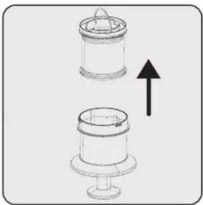
Remove the inlet foam inside the metal filter.
Remove the dust on the metal filter and inlet foam by tapping them to a hard surface such as a waste bin or by using a brush.
Install the inlet foam to the metal filter.
natural_image
Mechanical assembly diagram showing a rotating component with directional arrow (no text or symbols)
natural_image
Technical line drawing of a mechanical component with three views (top, front, side), no text or symbols present.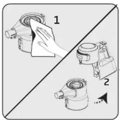
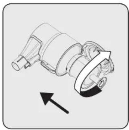
Install the metal filter inside the dust reservoir (11) by rotating it clockwise.
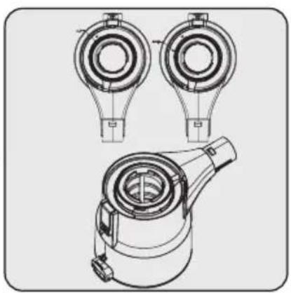
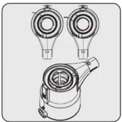
While installing the metal filter and inlet foam to the dust reservoir you have detached them from, place them as per the lock symbols on the dust reservoir.
- Wipe the body (10) with a wet cloth.
- Install the body (10) to the dust reservoir (11).
5 Cleaning and maintenance
5.2 Cleaning of the metal filter and inlet foam

The metal filter and inlet foam shall be cleaned regularly.
natural_image
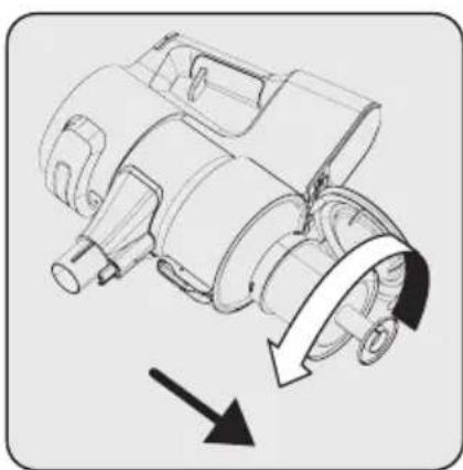
Mechanical component diagram showing a rotating assembly with directional arrows (no text or symbols)Remove the metal filter and inlet foam inside the dust reservoir (11) by rotating the metal filter counterclockwise.

natural_image
Diagram showing two cylindrical mechanical components with an upward arrow indicating motion or assembly (no text or symbols)Remove the inlet foam inside the metal filter.

natural_image
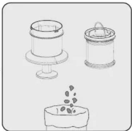
Three hand-drawn illustrations of containers: a cylindrical container, a lid with lid, and a small container with seeds (no text or symbols)Remove the dust on the metal filter and inlet foam by tapping them to a hard surface such as a waste bin or by using a brush.
natural_image
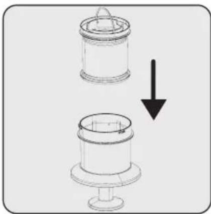
Diagram showing two cylindrical components with a downward arrow indicating transformation or change (no text or symbols)Install the inlet foam to the metal filter.

natural_image
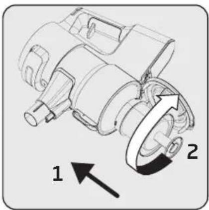
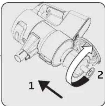
Mechanical diagram of a motor or pump assembly with two labeled parts (1 and 2), showing rotational motion arrows (no text or symbols beyond labels)Install the metal filter and inlet foam inside the dust reservoir (11) by rotating the metal filter clockwise.
5 Cleaning and maintenance

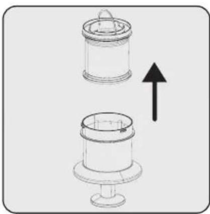
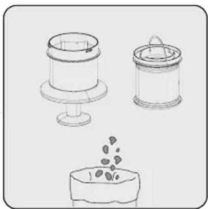
Clean the metal filter and inlet foam by washing under running cold water once a month after removing the dust on them.
natural_image
Mechanical assembly diagram showing a motor with rotational motion arrows (no text or labels)Remove the metal filter and inlet foam inside the dust reservoir (11) by rotating the metal filter counterclockwise.

natural_image
Diagram of two cylindrical mechanical components with an upward arrow indicating motion (no text or symbols)Remove the inlet foam inside the metal filter.

natural_image
Three line drawings of containers: a cylindrical container, a cylindrical container with lid, and a container with seeds or seeds emerging from its surface (no text or symbols)Remove the dust on the metal filter and inlet foam by tapping them to a hard surface such as a waste bin or by using a brush.

CAUTION: Wash with cold water. Warm water deteriorates the structure of the filter.
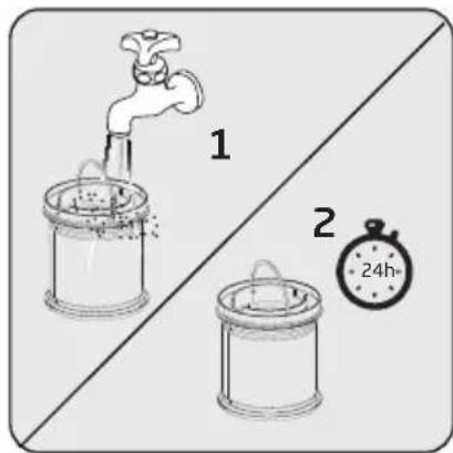
Wash the inlet foam under running cold water and let it dry.
natural_image
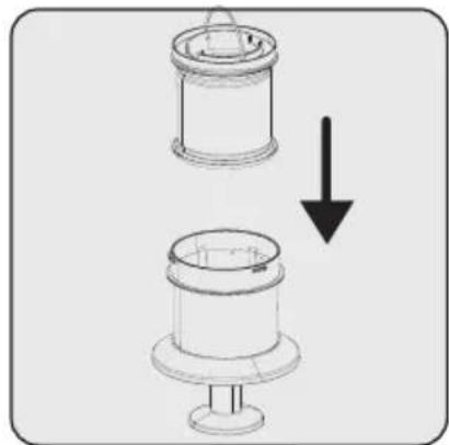
Diagram showing two mechanical components with a downward arrow indicating motion (no text or symbols)Install the dried inlet foam to the metal filter.

natural_image
Mechanical assembly diagram showing a rotating motor with labeled parts 1 and 2 (no text or symbols beyond labels)Install the metal filter and inlet foam inside the dust reservoir (11) by rotating the metal filter clockwise.

It may 24 to 48 hours to dry the washed inlet foam. Reinstall it once you are sure that it is dried.
5 Cleaning and maintenance
5.3 Cleaning of the EPA E12 Filter and outlet foam

Clean the EPA E12filter and outlet foam regularly.

CAUTION: Do not wash the EPA E12 filter.
natural_image
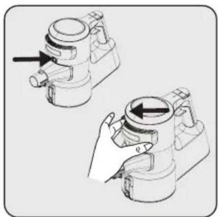
Illustration of two mechanical components with arrows indicating motion, no text or symbols presentRemove the lid simultaneously while pressing the EPA E12 filter release button.

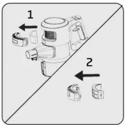
Remove the EPA E12 filter and the outlet foam inside it.

natural_image
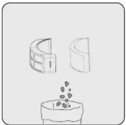
Illustration of three 3D geometric shapes (cave, lens, and bowl) with a pile of granular material emerging from the bowl (no text or symbols)Remove the dust on the EPA E12 filter and outlet foam by tapping them to a hard surface such as a waste bin or by using a brush.
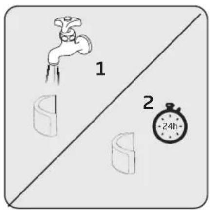
Inspect the outlet foam regularly. Clean it by washing under running cold water after removing the dust on them in case of excessive dust. Reinstall it once it is dried.

natural_image
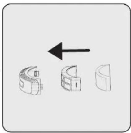
Three 3D mechanical parts with an arrow indicating direction (no text or symbols)Install the EPA E12 filter and outlet foam to the lid.

natural_image
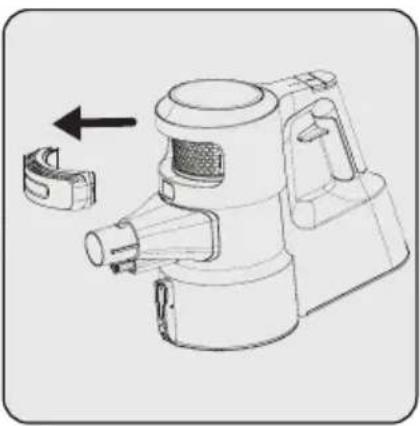
Technical line drawing of a hand-operated spray gun with a handle and clamped component (no text or symbols)Place the lid back.

CAUTION: Wash with cold water. Warm water deteriorates the structure of the filter.
5 Cleaning and maintenance
5.4 Cleaning of the brush

CAUTION: Do not wash the turbo brush (8) and the main roll brush.
natural_image
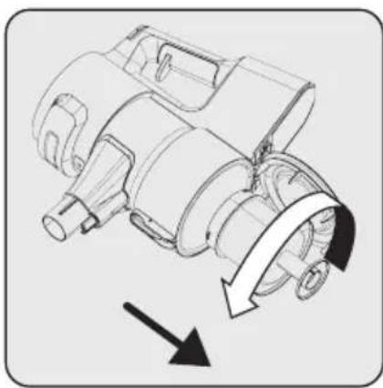
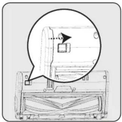
Technical line drawing of a mechanical component with an inset magnified view showing a detail (no text or symbols)To remove the electric turbo brush (8), keep the roll brush release tab pressed so that the lock shall be opened in the direction of the arrow, rotate the roll cover towards yourself and pull it to the left.

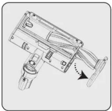
natural_image
Technical line drawing of a mechanical device with a directional arrow indicating motion (no text or symbols present)
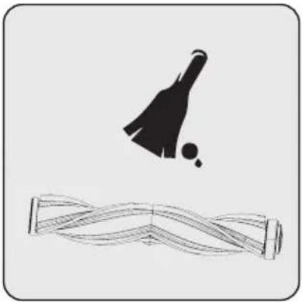
natural_image
Abstract line drawing of a stylized object above a wavy rectangular frame (no text or symbols)Remove the main roll brush. Remove the dust on it by tapping it
lightly to a hard surface or remove the dust with a brush. If any hair, etc. is tangled, remove it by cutting it off.
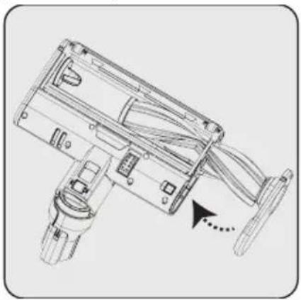
natural_image
Technical line drawing of a mechanical device with no visible text or symbolsRe-install the main roll brush after cleaning it. A "click" is heard from the tab.

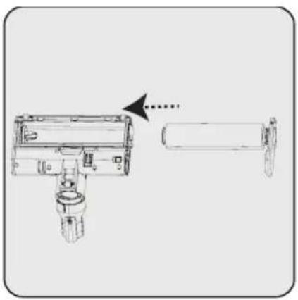
natural_image
Technical line drawing of a mechanical device with an arrow indicating transformation (no text or symbols)You may replace the main roll brush with delicate hard floor roll as per your preferences.
5 Cleaning and maintenance
5.5 Removal of the blockages
natural_image
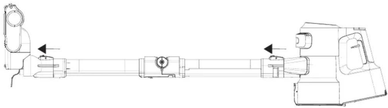
Technical line drawing of a mechanical assembly with two shafts and housing (no text or symbols)When you see the vacuum duct blockage warning on the screen (4), detach the brush (8) from the wand (6) to remove the blockages. Detach the wand (6) from the body of the appliance (10).
natural_image
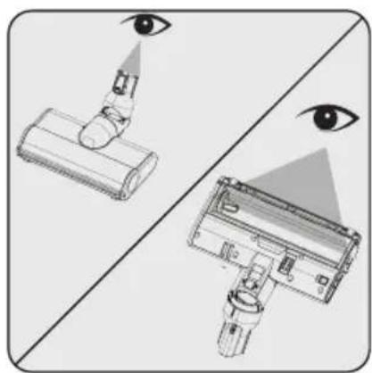
Diagram showing eye detection mechanism with two views of a device (no text or symbols present)Inspect the connection point of the brush (8) and the vacuum nozzle. Remove any foreign materials.
natural_image
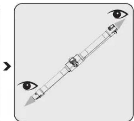
Diagram showing a human eye with a vertical line and a small object inside, no text or symbols presentInspect the inlet and outlet of the foldable wand (6). Remove any foreign materials.
natural_image
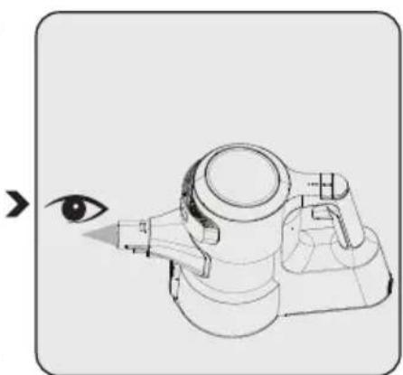
Line drawing of a stylized eye with a camera and lens, no text or symbols presentInspect the vacuum nozzle of the appliance body (10). Remove any foreign materials.
5 Cleaning and maintenance
5.6 Storage
- If you do not plan to use the appliance for a long while, store carefully.
- Unplug the appliance.
- Ensure that the appliance is kept out of reach of children.
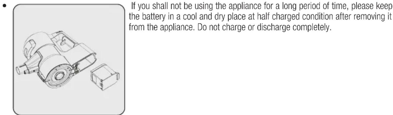
- Store the battery on a non-conducting material, and do not allow the battery to contact metal directly. This shall damage the battery.
5.7 Transportation and handling
- Keep the appliance in its package during transportation and handling. The package will protect the appliance against physical damage.
- Do not place heavy objects on the appliance or the package. The appliance may get damaged.
- If the appliance is dropped, it may malfunction or permanent damage may be inflicted.

CAUTION: Check the following points before asking for repair assistance from the service department.
| PROBLEM POSSIBLE CAUSE SOLUTION | ||
| Not operating | Battery is discharged. Charge it. | |
| Battery may be unseated. | Remove the battery and install it again. | |
| Vacuum connection is blocked. | Separate the appliance as body (10), brush (8) and wand (6). Inspect and clean the connection points. | |
| Suction power is getting reduced. | Dust reservoir (11) is full. | Clean the dust reservoir (11) and the filter. |
| You may have reached the cleaning period of the filters. | Clean the filters. | |
| Filters may be deformed as a result of operation and their replacement period may have come. | Please contact the customer services to buy a new filter. | |
| Motor inlet foam is not cleaned. | Clean the filters and recharge the appliance. | |
| Hair and similar materials may have tangled on the rotating roll on the turbo brush (8). | Clean the turbo brush roll. | |
| There is disturbing noise from the motor. | Vacuum connection is blocked. | Separate the appliance as body (10), brush (8) and wand (6). Inspect and clean the connection points. |
| Something may have stuck between the dust reservoir and the filter. | Open the dust reservoir and inspect the filter area. | |
| Cannot charge the vacuum cleaner. | The vacuum cleaner is not installed to the charging dock (15). | Install the vacuum cleaner to the charging dock (15). Make sure that it is seated properly. Check the connection. |
| Operates for a very short time after charging. | It is not charged for the adequate period. | Charge for 4-5 hours as per the instructions. |
| Motor inlet foam is not cleaned. | Clean the filters and recharge the appliance. | |
| Battery life is deteriorated. | Contact the customer services to buy a new battery. | |
| The colour indicator on the screen is illuminated in red. | Your appliance is about to discharged. | Charge it. |
| The animation indicating that the brush is blocked is displayed on the screen and the appliance has stopped operating. | Hair and similar materials may have tangled on the rotating roll on the turbo brush (8). | Clean the turbo brush roll. |
6 Problems and remedies
| The animation indicating that the vacuum is blocked is displayed on the screen and the appliance has stopped operating. | A blockage has occurred on the vacuum duct. | Remove the blockages. |
| The animation indicating that the filter is blocked is displayed on the screen and the appliance has stopped operating. | Filters are filled with excessively dust. | Clean the motor inlet foam and the metal filter. |
| The appliance has stopped operating while being operated. When the appliance is connected to charge, the charging screen is displayed on the screen. But, the battery percentage does not change. | Battery is faulty. Contact the customer services. | |
| The appliance stopped operating without any warning animation being displayed on the screen. | Battery may be overheated. | Wait for appliance to cool down and try to operate it again. |
| While charging, 1 LED light on the appliance flashes rapidly in red and the battery percentage on the screen does not change. | You may have inadvertently plugged the adaptor of another appliance, and thus the charge current is excessive. | Use the proper adaptor. |
| While charging, 1 LED light on the appliance is illuminated solidly in red and the battery percentage on the screen does not increase. | Battery be overheated than expected. | Contact the customer services. |
| While charging, 1 LED light on the appliance flashes both in red and white alternately and the battery percentage on the screen does not is shown as 00%. | The Body (10) is not installed properly to the charging dock (15). Or the battery is not installed properly to the body of the appliance. | Remove the adaptor (19) from the charging dock (15) and remove the body (10) from the charging dock. Ensure that the battery is installed properly on the body. Install the body (10) to the charging dock again and plug the adaptor to the charging dock again. |
| A bad smell (light humidity, dust, plastic material odour) occurs on the air outlet. | Have you purchased the appliance within the last 3 months? | It is normal that a bad smell (light odour of plastic) occurs within 3 months after the purchase date. |
| The dust reservoir (11) and the filters are not cleaned properly. | Clean the dust reservoir (11) and the filters. | |
| Filters may be installed while wet after they are washed. | Remove the filters and ensure that they are dry before installing them to the appliance. | |
| Filters may be deformed as a result of the frequency of operation and their replacement period may have come. | Please contact the customer services to buy a new filter. |
beko
natural_image
Simple line drawing of a grid pattern with circular motifs inside (no text or symbols)SD 8161
RU
natural_image
Line drawing of a hand holding a small mechanical device with arrows indicating motion or assembly (no text or symbols)natural_image
Diagram showing mechanical assembly with arrows indicating motion or force direction (no text or symbols)
natural_image
Technical illustration of a vacuum cleaner with attached clamp stand (no text or symbols)natural_image
Circular icon with battery and 0% symbol inside a dark ring (no text or numbers)natural_image
Line drawing of a vacuum cleaner with attached circuit board (no text or symbols)natural_image
Diagram of a vacuum cleaner with attached device, showing internal components and part outline (no text or symbols)natural_image
Icon of a ceiling light bulb inside a yellow circular frame (no text or symbols)natural_image
Circular icon with battery and 0% symbol, no text or numbers presentnatural_image
Circular icon with a white chimney and ruler symbol on dark background, no text or numbers present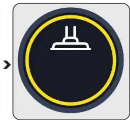
natural_image
Circular icon with a white chimney symbol on a dark background, no text or numbers present.
natural_image
Circular icon with a white chimney symbol on a dark background, enclosed in a yellow ring (no text or numbers)natural_image
Circular icon with a white chimney and horizontal line, no text or symbols present.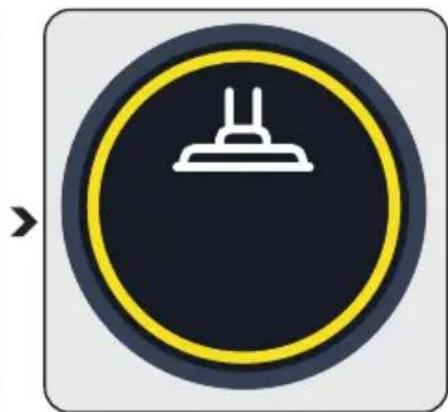
natural_image
Circular traffic sign with a white chimney icon on a dark background, no text or symbols present.
natural_image
Circular icon with a white chimney and ruler symbol on dark background, no text or numbers presentnatural_image
Circular icon with a red traffic light and an exclamation mark, no text or symbols present.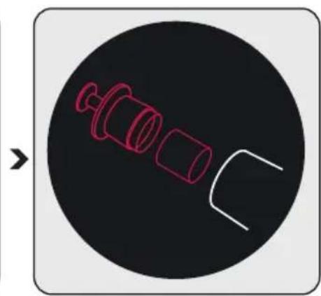
natural_image
Diagram of a mechanical component with red outline and white outline, no text or symbols present4 Эксплуатация
flowchart
graph TD
    A["Initial component"] --> B["Inserting part"]
    B --> C["Internal structure with internal components"]
    C --> D["Modified assembly"]
    D --> E["Final product"]
natural_image
Technical illustration of a vacuum cleaner with multiple tool tips and a close-up view of the component (no text or symbols)natural_image
Technical line drawing of a mechanical device with an arrow indicating transformation or assembly (no text or symbols present)natural_image
Illustration of a hand cleaning a mechanical device with a cloth (no text or symbols)natural_image
Illustration of a robotic arm pouring granular material into a container (no text or symbols)natural_image
Technical illustration of a mechanical component with numbered parts and directional arrows (no text or symbols)natural_image
Mechanical assembly diagram showing a rotating component with directional arrows indicating motion (no text or symbols)
natural_image
Technical line drawing of a mechanical component with three views (top, front, side), no text or symbols present.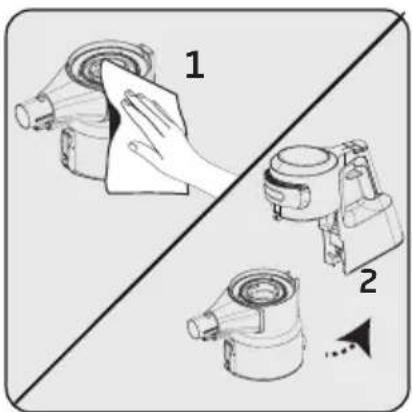
natural_image
Mechanical component diagram showing a rotating assembly with directional arrows (no text or symbols)natural_image
Diagram of two cylindrical mechanical components with an upward arrow indicating motion (no text or symbols)natural_image
Three line drawings of containers: a cylindrical container, a lid with a handle, and a bowl with seeds (no text or symbols)natural_image
Diagram showing two mechanical components with a downward arrow indicating motion (no text or symbols)natural_image
Mechanical diagram of a pump or motor assembly with labeled parts 1 and 2 (no text or symbols beyond labels)natural_image
Mechanical assembly diagram showing a motor with rotating shaft and directional arrow (no text or labels)natural_image
Diagram of two cylindrical mechanical components with an upward arrow indicating motion (no text or symbols)natural_image
Three line drawings of containers: a cylindrical container, a lid with a handle, and a tray with seeds (no text or symbols)natural_image
Diagram showing two cylindrical objects with a downward arrow indicating transformation or change (no text or symbols present)natural_image
Mechanical assembly diagram showing a motor and gear mechanism with directional arrows (no text or symbols)natural_image
Illustration of two mechanical components with arrows indicating motion, no text or symbols presentnatural_image
Illustration of three abstract 3D shapes with a small container pouring granular material (no text or symbols)natural_image
Three 3D mechanical parts with an arrow indicating direction (no text or symbols)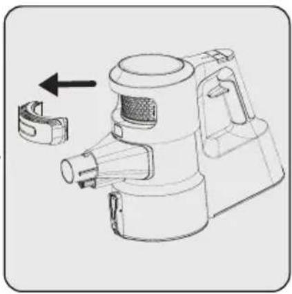
natural_image
Technical line drawing of a spray gun with a handle and internal components, showing no text or symbols.natural_image
Technical line drawing of a mechanical device with a magnified circular detail showing a component (no text or symbols)natural_image
Technical line drawing of a mechanical device with a directional arrow indicating motion (no text or symbols)natural_image
Abstract illustration of a trophy and a wavy ribbon-like shape (no text or symbols)natural_image
Technical line drawing of a mechanical device with no visible text or symbolsnatural_image
Technical line drawing of a mechanical device with an arrow indicating assembly or transformation (no text or symbols present)natural_image
Technical line drawing of a mechanical assembly with directional arrows indicating motion or force directions (no text or symbols present)natural_image
Diagram showing eye detection mechanism with magnified views of a device (no text or symbols)natural_image
Diagram of a human eye with a vertical arrow and segmented components, no text or symbols presentnatural_image
Illustration of a human eye with a stylized optical device, no text or symbols presentnatural_image
Technical line drawing of a mechanical component with a housing and part, no visible text or symbols12 months breakdown and repair guarantee
Guarantor: Beko plc, 1 Greenhill Crescent, Watford, Hertfordshire. WD18 8UF
The guarantee does not in any way diminish your statutory or legal rights.
Your appliance has the benefit of our manufacturer's guarantee which covers the product for 12 months from the date of original purchase.
This gives you reassurance that if within that time, your appliance is proven to be defective because of either workmanship or materials, we will at our discretion either repair or replace your appliance.
The appliance must be correctly installed, located and operated in accordance with the instructions contained in the user manual. !The guarantor disclaims any liability for accidental or consequential damage.
The Guarantee is subject to the following conditions:
■ Documentary proof of the original purchase date is provided.
- The appliance has been installed and operated correctly and in accordance with our operating and maintenance instructions.
The appliance is used only on the electricity supply on the rating plate.
The appliance has only been used for normal domestic purposes.
The appliance has not been altered, serviced, dismantled or otherwise interfered with by any person.
■ The appliance is used in the United Kingdom or Republic of Ireland.
■ Any parts removed during repair work or any product that has been replaced becomes our property.
The guarantee is not transferrable if the product is resold.
The Guarantee does not cover:
■ Transit, installation or delivery damage.
■ Accidental damage.
- Misuse or abuse.
- Replacement of any consumable item or accessories. These include but are not limited to: plugs, cables, light bulbs, knobs, filters and flaps.
- Repairs or replacements required as a result of unauthorised repairs or inexpert installation that fails to meet the requirements contained in the user guide or instruction book.
■ Repairs to products used in commercial or non-residential household premises.
How to obtain after sales service, help or general advice
Please keep your purchase receipt or other proof of purchase in a safe place as you will need to show us this document if your product requires attention within the guarantee period.
Please also record your product details below, which will allow you to access our services more quickly and help us identify your product. The model number is printed on the front of the user guide and the serial and model number is shown on your products rating plate.
| Model number | Serial number | Purchased from | Date of purchase |
Please call our UK based Customer Service department if you need help or advice from us:
United Kingdom and Northern Ireland: 0333 207 9710
Republic of Ireland: 01 862 3411
You can also contact us through our website: www.beko.co.uk
natural_image
Technical line drawing of a mechanical device with a housing and casing (no text or symbols)natural_image
Technical line drawing of a mechanical assembly with directional arrows indicating motion or force directions (no text or symbols present)natural_image
Diagram showing eye shadow application on a device versus a device with a magnified view (no text or symbols)natural_image
Illustration of a mechanical device with two eyes and a tool, no text or symbols presentnatural_image
Illustration of a human eye interacting with a mechanical device (no text or symbols)natural_image
Technical line drawing of a mechanical device with an inset circular detail showing a component (no text or symbols)natural_image
Technical line drawing of a mechanical device with internal components and a directional arrow (no text or symbols)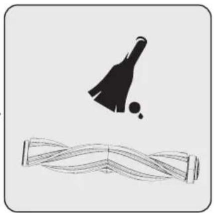
natural_image
Simple line drawing of a tennis ball and a wavy track (no text or symbols)natural_image
Technical line drawing of a mechanical device with no visible text or symbolsnatural_image
Technical line drawing of a mechanical device with an arrow indicating transformation or assembly (no text or symbols present)natural_image
Two technical illustrations of a mechanical component being held, showing a hand pressing a circular component (no text or symbols present)natural_image
Simple line drawing of a container with granular substance and two curved containers above it (no text or symbols)natural_image
Three 3D mechanical parts with a black arrow pointing from one to the other (no text or symbols)natural_image
Technical line drawing of a mechanical device with a bracket and handle, showing no text or symbols.natural_image
Mechanical component diagram showing a rotating assembly with directional arrows (no text or symbols)natural_image
Diagram of two cylindrical mechanical components with an upward arrow indicating motion (no text or symbols)natural_image
Three hand-drawn illustrations of food containers: a cylindrical container, a lid with lid, and a tray with granular substance (no text or symbols)natural_image
Diagram showing two mechanical components with a downward arrow indicating motion (no text or symbols)natural_image
Mechanical component diagram showing a rotating assembly with two labeled parts (1 and 2), no text or symbols present.natural_image
Mechanical component diagram showing a rotating fan or pump mechanism with directional arrows (no text or symbols)natural_image
Technical line drawing of two mechanical components with an upward arrow indicating motion (no text or symbols)natural_image
Three line drawings of kitchenware: a cylindrical container, a cylindrical container with lid, and a tray with food items (no text or symbols)natural_image
Diagram showing two cylindrical containers with a handle, one being dropped and the other held by a stand (no text or symbols)natural_image
Mechanical assembly diagram showing a motor and gear mechanism with labeled parts 1 and 2 (no text or symbols beyond labels)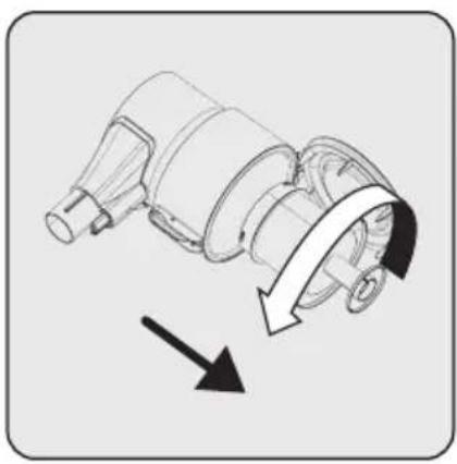
natural_image
Mechanical component diagram showing a rotating shaft and housing with directional arrows indicating motion (no text or symbols)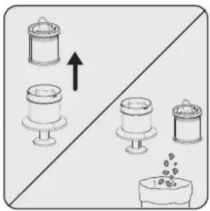
natural_image
Diagram showing four containers with an upward arrow, one container filled with granular material, another with a bowl and lid, and a third with granular material (no text or symbols)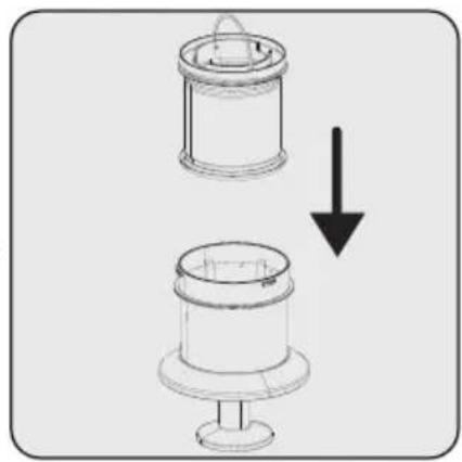
natural_image
Diagram showing a mechanical component with a downward arrow indicating transformation (no text or symbols present)natural_image
Mechanical assembly diagram showing a rotating component with directional arrows indicating motion (no text or symbols)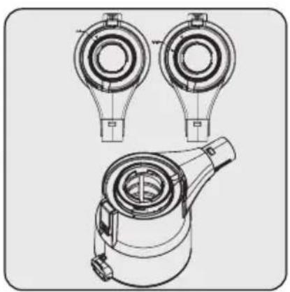
natural_image
Technical line drawing of a mechanical component with three views (top, front, side), no text or symbols present.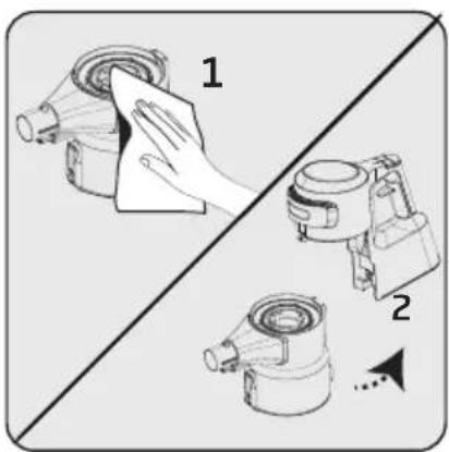
natural_image
Illustration of a hand cleaning a mechanical device with a cloth (no text or symbols)natural_image
Illustration of a manual robotic device pouring granular material into a container (no text or symbols)natural_image
Technical illustration of a mechanical device with three views (1, 2, and 3), showing internal components and directional arrows (no text or symbols)natural_image
Diagram of a mechanical device with a tool and arrow indicating process (no text or symbols)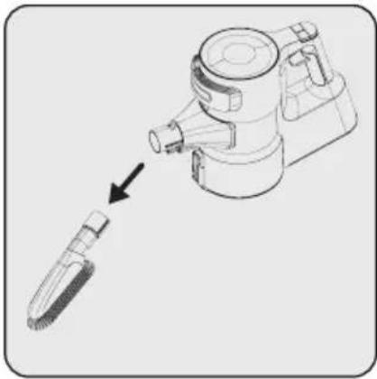
natural_image
Diagram of a mechanical device with a tool inserted, showing a magnified view of the component (no text or symbols present)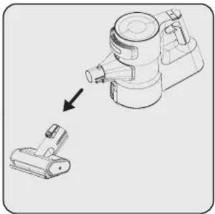
natural_image
Diagram showing a vacuum cleaner being placed on a small mechanical component (no text or symbols present)natural_image
Diagram showing a device with a cylindrical component and a separate cylindrical component, no text or symbols present.natural_image
Illustration of a handwashing device with three tool tips and a brush (no text or symbols)natural_image
Circular icon with a white chimney and black base, no text or symbols present.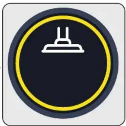
natural_image
Circular traffic sign with a white exhaust chimney icon on dark background (no text or symbols)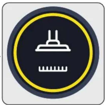
natural_image
Circular icon with a white chimney and ruler symbol on dark background, no text or numbers presentnatural_image
Black circular icon with a red traffic sign and an exclamation mark, no text or symbols present.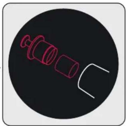
natural_image
Simple line drawing of a mechanical component with three cylindrical parts and a curved cutout, set against a black circular background (no text or symbols)natural_image
Icon of a ceiling light bulb inside a yellow circular frame (no text or symbols)الشحن 4.3.3
natural_image
Circular icon with battery and 0% symbol inside a teal ring (no text or numbers)natural_image
Circular icon with a white chimney and ruler symbol on dark background, no text or numbers present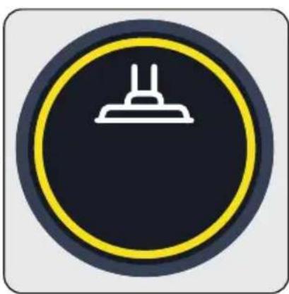
natural_image
Circular traffic sign with a white chimney icon on a dark background, enclosed in a yellow ring (no text or symbols)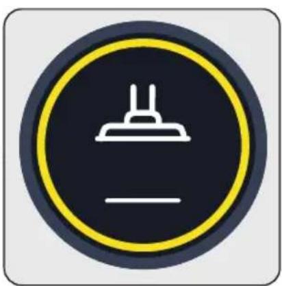
natural_image
Circular traffic sign with a white chimney icon on dark background, no text or symbols presentLCD 4.3
natural_image
Line drawing of a vacuum cleaner with attached circuit board and warning symbol (no text or labels)natural_image
Line drawing of a vacuum cleaner with attached device, showing internal components and wiring (no text or symbols)natural_image
Technical illustration of a vacuum cleaner with a mounted device and base mount (no text or symbols)natural_image
Circular icon with battery and 0% symbol, no text or numbers presentnatural_image
Technical line drawing of a handheld device with arrows indicating motion or assembly (no text or symbols)natural_image
Diagram showing a mechanical assembly with two components and directional arrows indicating motion (no text or symbols)natural_image
Technical diagram of a vertical spray gun assembly with a magnified inset showing internal components (no text or labels)natural_image
Diagram showing a vertical pole with two downward arrows indicating force or movement (no text or symbols present)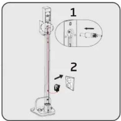
natural_image
Simple line drawing of a decorative border with circular motifs (no text or symbols)SD 8161
AR
- Please read this guide first!
- Symbols and their meanings
- Important safety and environmental instructions
- General safety
- Compliance with the WEEE Directive and disposal of the waste product
- Packaging information
- Waste batteries
- Actions to be taken for energy saving
- Overview
- Controls and components
- Technical data
- Installation
- Intended use
- Installation of the mobile charging dock
- Installation of the body and the brush
- Operation
- Charging the appliance
- Operation
- LCD Display
- Main Screen
- Remaining operating period:
- Colour indicator:
- Low speed level
- Medium speed level
- Maximum speed level
- Changing the speed
- Charging
- Automatic floor detection
- Warning screens
- Filter cleaning warning
- Brush blockage warning
- Vacuum duct blockage warning
- Accessories
- Narrow mouth nozzle (21):
- Cleaning and maintenance
- Cleaning of the dust reservoir
- Cleaning of the metal filter and inlet foam
- Cleaning of the EPA E12 Filter and outlet foam
- Cleaning of the brush
- Removal of the blockages
- Storage
- Transportation and handling
- Problems and remedies
- beko
- Эксплуатация
- months breakdown and repair guarantee
- The Guarantee is subject to the following conditions:
- The Guarantee does not cover:
- How to obtain after sales service, help or general advice
- LCD 4.3
Brand : Arçelik
Model : Imperium Go Plus SD 9161
Category : Vacuum Cleaner