
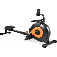
XTR4 II - Elliptical bike Proflex - Free user manual and instructions
Find the device manual for free XTR4 II Proflex in PDF.


| Product Type | Elliptical Cross Trainer |
| Model | XTR4 II |
| Brand | Proflex |
| Overall Dimensions (L x W x H) | Approximately 160 x 70 x 170 cm |
| Max User Weight | 120 kg (265 lbs) |
| Product Weight | Approximately 45 kg |
| Flywheel Weight | 8 kg |
| Resistance System | Magnetic, manual or electronic (8-16 levels) |
| Power Supply | Batteries (2x AAA) or optional AC adapter |
| Display | LCD with time, distance, speed, calories, pulse, scan |
| Heart Rate Monitor | Hand pulse sensors on handles |
| Programs | 12 preset programs plus manual mode |
| Pedal Type | Adjustable anti-slip pedals with straps |
| Frame Material | Heavy-duty steel tubing |
| Maintenance | Regular cleaning, check bolts, lubricate moving parts |
| Safety Features | Emergency stop, stable base, no sharp edges |
| Spare Parts Availability | Contact Proflex support or authorized dealers |
| Warranty | 2 years on frame, 1 year on parts |
Frequently Asked Questions - XTR4 II Proflex
User questions about XTR4 II Proflex
0 question about this device. Answer the ones you know or ask your own.
Ask a new question about this device
Download the instructions for your Elliptical bike in PDF format for free! Find your manual XTR4 II - Proflex and take your electronic device back in hand. On this page are published all the documents necessary for the use of your device. XTR4 II by Proflex.
USER MANUAL XTR4 II Proflex
[Revision 5.0 February 2022]
Safety
Basic precautions, including the following important safety instructions, should always be followed when using this equipment. Read all instructions before use.

Before beginning any exercise program, consult your physician. This is especially important for people over 35 years of age or who have pre-existing health problems. Read all instructions before using any fitness equipment. Do not operate this exercise equipment without properly fitted guards, as the moving parts can present a risk of serious injury if exposed.
- Use this product for its intended use only as described in this user manual. Do not use attachments not supplied or recommended by the manufacturer.
• Maximum weight capacity = 100 kg. - Do not attempt any maintenance or adjustments other than those described in this user manual. Should any problems arise, discontinue use and consult an authorized service centre or personnel.
- Any information or data provided by the equipment is a guide only and is not to be used as medical data or scientific evidence.
• Do not use the unit outdoors. - Keep children and pets away from the equipment while in use.
- Elderly or disabled users should only use the equipment in the presence of an adult who can provide assistance if required.
- Do not operate where aerosol (spray) products are in use or where adequate oxygen is not available.
- Keep dry – do not operate in wet or moist conditions.
- Keep the unit on a solid, level surface with a minimum safety area clearance of two meters around it. Be sure the area around the equipment remains clear of any obstructions during use.
• The equipment is for domestic household use only.
• One person only should use the equipment at a time. - Wear comfortable and suitable clothing when using the equipment. Do not use the equipment barefoot or in socks. Always wear appropriate, enclosed athletic footwear. Never wear loose or baggy clothing as it can become caught on the equipment and create a hazard.
• Always hold on to the handrails while using the equipment. - Do not leave children unsupervised near or on the equipment.
• Children should not be allowed to play or operate the equipment at any time. - This equipment is not intended for use by persons (including children) with reduced physical, sensory or mental capabilities, or lack of experience and knowledge, unless they have been given supervision or instruction concerning use of the equipment by a person responsible for their safety.
- Keep hands clear of all moving parts. Never place hands or feet off the handles or pedals while the equipment is in use.
• Before using the equipment, check that all visible fasteners are sufficiently tightened and secure. - Handle or move the equipment with due care to avoid personal injury or damage to the equipment.
Table of Contents
Safety....2
Parts Identification....4
Accessories Chart 8
Spare Parts 9
Assembly 10
Operation 19
Console and Functions 19
Setting a Pre-Set Session Time / Distance / Calorie / Pulse....20
Adjusting Resistance....20
Care, Maintenance and Troubleshooting....21
Cleaning....21
Storage 21
Troubleshooting 21
Specifications....22
Warm-Up and Cool-Down Routine....23
Parts Identification
The equipment comes partially assembled. The unit comes with the following parts. Ensure that all parts are included before assembly.
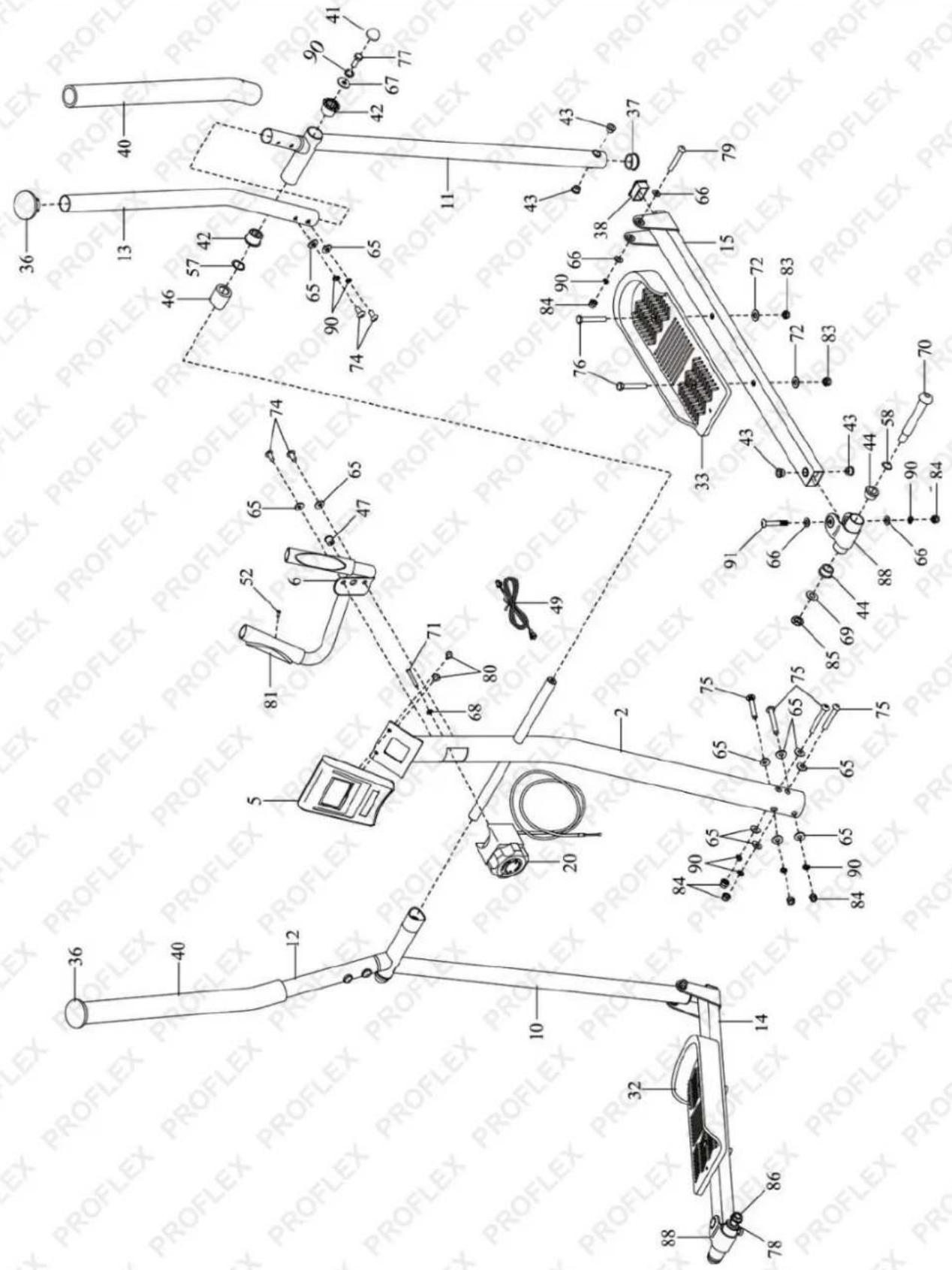
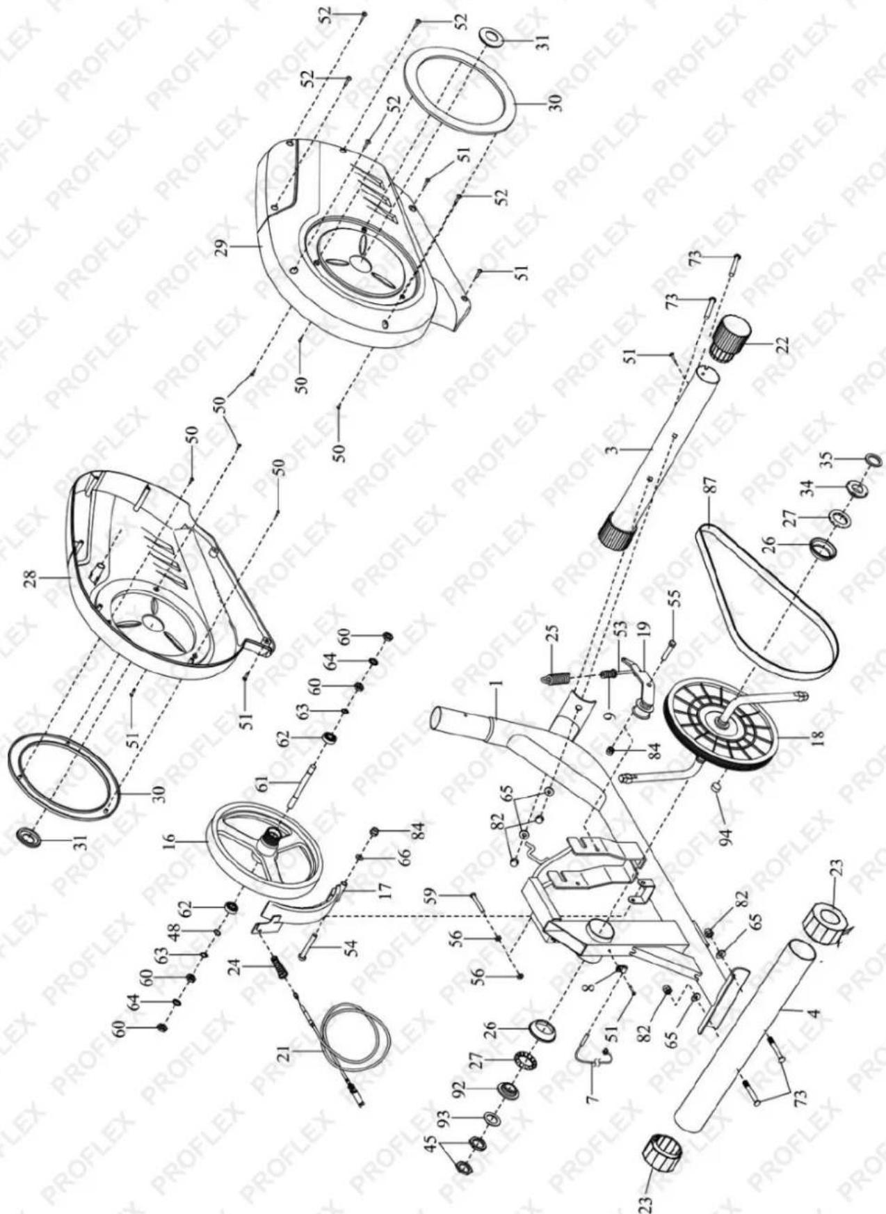
| No. | Qty. | Description |
| 1 | 1 | Frame |
| 2 | 1 | Main Pipe |
| 3 | 1 | Front Foot Pipe |
| 4 | 1 | Rear Foot Pipe |
| 5 | 1 | Monitor |
| 6 | 1 | Senior Handlebar |
| 7 | 1 | Above Signal Transmission Cable |
| 8 | 1 | Clamp |
| 9 | 1 | Spiral Nut |
| 10 | 1 | Left Swing Arm |
| 11 | 1 | Right Swing Arm |
| 12 | 1 | Left Handlebar |
| 13 | 1 | Right Handlebar |
| 14 | 1 | Left Pedal |
| 15 | 1 | Right Pedal |
| 16 | 1 | Flywheel |
| 17 | 1 | C-magnet |
| 18 | 1 | Pulley/Crank |
| 19 | 1 | Idler |
| 20 | 1 | Above Resistance Cable |
| 21 | 1 | Lower Resistance Cable |
| 22 | 2 | Transport Wheel |
| 23 | 2 | Levelling Cap |
| 24 | 1 | Resistance Spring |
| 25 | 1 | Tension Spring |
| 26 | 2 | Bearing Cup |
| 27 | 2 | Ball Bearing |
| 28 | 1 | Left Shield |
| 29 | 1 | Right Shield |
| 30 | 2 | Large Accent Ring |
| 31 | 2 | Small Accent Ring |
| 32 | 1 | Left Pedal |
| 33 | 1 | Right Pedal |
| 34 | 1 | Right Bearing Race |
| 35 | 1 | Right Crank Spacer |
| No. | Qty. | Description |
| 49 | 1 | Below Signal Transmission Cable |
| 50 | 6 | M3 x 7mm Screw |
| 51 | 7 | M4 x 20mm Self-tapping Screw |
| 52 | 7 | M4 x 20mm Screw |
| 53 | 1 | M6 x 100mm Hex Bolt |
| 54 | 1 | M8 x 60mm Hexagon Socket Bolt |
| 55 | 1 | M8 x 16mm Hex Bolt |
| 56 | 2 | M6 Screw Nut |
| 57 | 2 | Pivot Wave Washer |
| 58 | 2 | M16 Wave Washer |
| 59 | 1 | M6 x 45mm Hexagon Socket Bolt |
| 60 | 4 | MIO Jam Nut |
| 61 | 1 | Flywheel Axle |
| 62 | 2 | Flywheel Bearing |
| 63 | 2 | Snap Ring |
| 64 | 2 | Star Washer |
| 65 | 18 | M8 Curved Washer |
| 66 | 9 | M8 Washer |
| 67 | 2 | Pivot Washer |
| 68 | 1 | M5 Curved Washer |
| 69 | 2 | MI3 Washer |
| 70 | 1 | Right M12 x 110mm Hexagon Socket Bolt |
| 71 | 1 | M5 x 45mm Screw |
| 72 | 4 | MIO Washer |
| 73 | 4 | M8 x 65mm Square Neck Bolt |
| 74 | 6 | M8 x 16mm Screw |
| 75 | 4 | M8 x 65mm Hexagon Socket Bolt |
| 76 | 4 | MIO x 45mm Hex Bolt |
| 77 | 2 | M8 x 20mm Hex Bolt |
| 78 | 1 | Left M12 x 110mm Hexagon Socket Bolt |
| 79 | 2 | M8 x 60mm Hexagon Socket Bolt |
| 80 | 2 | M5 x 12mm Screw |
| 81 | 2 | Sensor Plug |
| 82 | 4 | M8AcomNut |
| 83 | 4 | MIO Screw Nut |
| No. | Qty. | Description |
| 36 | 2 | Upper Arm Cap |
| 37 | 2 | Lower Arm Cap |
| 38 | 2 | Pedal Arm Cap |
| 39 | 1 | M8 Allen Wrench |
| 40 | 2 | Handlebar Grip |
| 41 | 2 | Pivot Cap |
| 42 | 4 | Pivot Bushing |
| 43 | 8 | Lower Arm Bushing |
| 44 | 4 | Pedal Arm Bushing |
| 45 | 2 | Crank Nut |
| 46 | 2 | Spacer |
| 47 | 1 | Grommet |
| 48 | 1 | MIO Wave Washer |
| No. | Qty. | Description |
| 84 | 8 | M8 Screw Nut |
| 85 | 1 | Right M12 Screw Nut |
| 86 | 1 | Left M12 Screw Nut |
| 87 | 1 | Drive Belt |
| 88 | 2 | Pedal Arm Connector |
| 89 | 1 | Multifunctional Wrench |
| 90 | 14 | M8 Split Washer |
| 91 | 2 | M8 x 55mm Bolt |
| 92 | 1 | Left Bearing Race |
| 93 | 1 | Left Crank Spacer |
| 94 | 1 | Pulley Magnet |
| 95 | 1 | M6 Allen Wrench |
| 96 | 1 | Plate Wrench |
Accessories Chart
The numbers in brackets are the codes of the part in the Parts Identification. If a part isn't in the accessories kit, please check if it was assembled. If any part is missing, distorted, or broken when you receive the package, please contact the manufacturer.

Spare Parts

Spare parts available for purchase, scan QR codes below:
QR Code SKU


FTNXTRPRFA4GR


FTNXTRPRFA4YW
Assembly
Step 1: Assemble the foot pipes


- To assemble both foot pipes, please prepare front foot pipe (No.3), rear foot pipe (No.4), four M8 curved washers (No.65), four M8 square neck bolts (No.73), four M8 acorn nuts (No.82) and socket wrench (No.89).
ATTENTION: There are two kinds of foot pipes. The front foot pipe has two wheels, another one doesn't have wheels. Assemble the front foot pipe with wheels in front of the main frame.
- Insert two M8 Square neck bolts from the bottom of each foot pipe, and then screw two M8 acorn nuts and two M8 curved washers by using the wrench. The wheels face outward.
Step 2: Connect the wires in the main pipe

- Adjust the resistance to the 8th gear. The resistance cable will become longer.
- Connect the signal transmission cables (No.7), (No.49). Then insert the bottom of above resistance cable (No.20) into the wire clip of metal bracket (No.21).
- Firmly pull the resistance cable upward and slide it into the top of the metal bracket.
- Reduce the resistance gear to prevent the resistance cable to fall out during assembly.
Step 3: Assemble the main pipe


- To assemble the main pipe, please prepare eight M8 curved washers (No.65), four M8 hexagon socket bolts (No.75), four M8 screw nuts (No.84), socket wrench (No.89), four M8 split washers (No.90) and M6 Allen wrench (No.97).
- Insert the main pipe into the frame.
- Insert a M8 hexagon socket bolt and a M8 curved washer into every hole of the joint.
- Screw in a M8 curved washer, a M8 split washer and a M8 screw nut in turn with M6 Allen wrench and socket wrench.
ATTENTION: Please be careful not to pinch the cable. Don't tighten all bolts until you finish all assembly steps. When tightening the bolts between the main pipe and frame, please ensure that 3 threads are visible outside the nut to avoid any wobbling.
Step 4: Assemble the swing arms

- Prepare left swing arm (No.10), right swing arm (No.11), two spacers (No.46), two pivot curved washers (No.57), two pivot washers (No.67), two M8 hexagon bolts (No.77), socket wrench (No.89), two M8 split washers (No.90) and two pivot caps (No.41).
ATTENTION: These spacers, washers and bolts were attached to the horizontal pipe.
- Smear sufficient grease on both sides of the horizontal pipe, or the machine might make noise during operation.
- Attach a spacer, a pivot curved washer and a swing arm to both sides of the horizontal pipe in turn.
- Screw a M8 hexagon bolt through a M8 split washer and a pivot washer with the socket wrench on both sides
- Cover two pivot caps on both sides.
Step 5: Assemble the pedal arms

- Prepare M8 Allen wrench (No.39), two M16 wave washers (No.58), two M13 washers (No.69), two M12 hexagon socket bolts (No.70) (No.78), two M12 screw nuts (No.85) (No.86) and plate wrench (No.96). Take the right pedal arm as an example. The assembly of the left pedal arm is in the same way.
- Smear sufficient grease on the M12 hexagon socket bolts, or the machine might make noise during operation.
- Insert a M12 hexagon socket bolt and a M16 wave washer to connect the pedal arm to the crank arm. Screw the left bolt anticlockwise and the right bolt clockwise.
- Screw a M13 washer and a M12 screw nut with M8 Allen wrench and plate wrench.
ATTENTION: The letters "L" and "R" are on the crank arms and the head of M12 hexagon socket bolts. The inner ring of the right M12 screw nut is white. The inner ring of the left M12 screw nut is black.
Step 6: Assemble the pedals

- Take the right pedal (No.15) as an example. The assembly of the left pedal (No.32) is in the same way.
ATTENTION: The baffles of the pedals should face inward.
- Put the pedal (No.33) on the right pedal arm (No.15) and insert two M10 hex bolts (No.76).
- Screw in two M10 plat washers (No.72) and two M10 screw nuts (No.83).
Step 7: Assemble the handlebars

-
Prepare left handlebar (No.12), right handlebar (No.13), four M8 curved washers (No.65), four M8 hexagon socket blots (No.74), four M8 split washers (No.90) and M6 Allen wrench (No.97). Take the right handlebar as an example. The assembly of the left handlebar is in the same way.
-
Insert the right handlebar in the right swing arms. Screw two M8 hexagon socket blots, two M8 split washers and two M8 curved washers with the Allen wrench
ATTENTION: The letters 'L' and 'R' are indicated on the handlebars.
Step 8: Assemble the sensor handlebar

- Attach the sensor handlebar (No.6) to the main pipe (No.2).
- Screw two M8 hexagon socket blots (No.74), and two M8 curved washer (No.65) with the M6 Allen wrench (No.97).
Step 9: Assemble the monitor

- Unscrew two M5*12mm screws (No.80) from the back of the monitor (No.5) with the socket wrench (No.89).
- Connect the cable of monitor (No.5) to the main pipe.
- Attach the monitor to the head of main pipe. Screw two M5 screws back.
- Insert the sensor plug to the monitor and install two AAA batteries.
ATTENTION: After assembly, please tighten all bolts of the above steps. Especially when tightening the bolts between the main pipe and frame, please ensure that 3 threads are visible outside the nut to avoid any wobbling.

Operation
Console and Functions
The equipment features a computerized display that provides you with workout information, such as duration, speed, distance travelled, pulse etc. The console activates as soon as a key is pressed or the pedals are moved. When the machine is not being used, the console switches off automatically after 4 minutes.

| RESET | MODE | SET |
| Control Description | |
| Display | Shows various information depending on current function. For example, current speed, used calories, current pulse etc. |
| Note: When displaying pulse, you must have both hands on the metal sensors on the stationary handlebar. If no pulse is detected, "P" may be displayed and some functions are unavailable • To approximately convert calories to kilojoules, multiply the number of calories by 4. | |
| MODE | Press to switch between available functions. The current function is indicated by having an arrow shown next to it:DIST - When in "setting" mode, program a target distance (range = 0 to 999.9 km).When exercising, shows the current distance travelled for the session.CAL - When in "setting" mode, program a target calorie amount (range = 10 to 9999 cal). When exercising, shows the current calories used for the session.ODO - When exercising, shows the current distance travelled for all sessions combined (returns to zero if the batteries are removed).PUL - When in "setting" mode, program a target heart rate (range = 80 to 180 bpm).When exercising, shows your current heart rate.TIME - When in "setting" mode, program a target session duration (range = 0 to 99 minutes and 59 seconds). When exercising, shows the current time elapsed for the session.SCAN - When exercising, automatically steps the display between each function every 4 seconds. |
| SET | Press to activate "setting" mode and to increase the current value when setting target values (for example, time, distance etc). |
| RESET | When in "setting" mode, press to return the current value to zero "0". |
Setting a Pre-Set Session Time / Distance / Calorie / Pulse
When training to pre-set session values, the console beeps once you have achieved each target value. For example, setting a time of 5 minutes, distance of 3km, calories used of 50, and pulse of 110 will cause the console to beep if your pulse reaches 110, beep again if you use 50 calories, beep again if you travel 3km and beep again after 5 minutes. You can set targets for all values, or whichever ones you want.
- Press MODE as required until the arrow is shown next to the required function (distance, calories, pulse or time).
- Press SET to enter "setting" mode and apply a target value. Press again to increase the value or hold down to more quickly increase the target value.
- Press MODE to step to the next function you want to set a target value for, then use SET to enter the value and so on. Repeat this process as required, then begin your workout.
To cancel the target value and start again, press RESET (any other currently set values will remain unchanged).
Adjusting Resistance
The resistance of the crank to being rotated can be adjusted. Increased resistance requires more effort and, therefore, uses more energy. To adjust crank resistance, rotate the knob on the central brace - 1 = least resistance, 8 = greatest resistance.

Care, Maintenance and Troubleshooting

Some maintenance activities described may be beyond the scope of some users. For procedures that you are not comfortable with or have the tools or experience for, have the service centre or qualified technician.
Cleaning
The equipment can be cleaned with a soft cloth and mild detergent. Do not use abrasives, solvents or harsh chemicals. Be careful not to get excessive moisture on the display panel as this may damage it.
After each use, wipe the unit of any sweat, dirt or liquids. Keep the equipment, especially the display console, out of direct sunlight to prevent damage to the screen.
Storage
Store the equipment in a clean and dry indoor environment. Never leave or use the unit outdoors.
Troubleshooting
The following information may assist in identifying a problem and rectifying it.
| Problem | Potential Reason | Correction |
| Pedals or handles tight or making noise. | A. Pedal bolts or retaining screws too tight.B. Pivots require lubricating. | A. Loosen fasteners so that wave washers are not compressed flat. For pedal bolts, hold bolts in positions when tightening nuts.B. Disassemble pivots, clean components, then smear with grease before reassembling. |
| Console not working. | A. Batteries no longer serviceable.B. Connection problem.C. Console problem. | A. Replace batteries.B. Check all connections are secure and wiring is not pinched or damaged. Replace is necessary.C. Replace console. |
When to Call for Help
This equipment is designed with user safety as a priority. In the event of equipment failure, call an authorized service centre or technician for servicing.
Specifications
Weight Capacity
100kg
Warm-Up and Cool-Down Routine
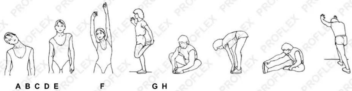
The warm-up routine is an important part of any workout. The purpose of warming up is to prepare your body for exercise and to minimize injuries. Warm up for two to five minutes before aerobic exercising. It should begin every session to prepare your body for more strenuous exercise by heating up and stretching your muscles, increasing your circulation and pulse rate, and delivering more oxygen to your muscles.
Always perform a cool-down routine after your workout, repeat these exercises to reduce soreness in tired muscles. The purpose of cooling down is to return the body to its resting state at the end of each exercise session. A proper cool-down slowly lowers your heart rate and allows blood to return to the heart.
A. Head Roll - Rotate your head to the right for one second, you should feel a stretching sensation up the left side of your neck. Then rotate your head back for one second, stretching your chin to the ceiling and letting your mouth open. Rotate your head to the left for one second, then drop your head to your chest for one second.
B. Shoulder Lift - Lift your right shoulder toward your ear for one second. Then lift your left shoulder up for one second as you lower your right shoulder.
C. Side Stretch - Open your arms to the side and lift them until they are over your head. Reach your right arm as far toward the ceiling as you can for one second. Repeat this action with your left arm.
D. Quadricep Stretch - With one hand against a wall for balance, reach behind you and pull your right foot up. Bring your heel as close to your buttocks as possible. Hold for 15 seconds and repeat with left foot.
E. Inner Thigh Stretch - Sit with the soles of your feet together and your knees pointing outward. Pull your feet as close to your groin as possible, then gently push your knees toward the floor. Hold for 15 seconds.
F. Toe Touch - Slowly bend forward from your waist, letting your back and shoulders relax as you stretch toward your toes. Reach as far as you can and hold for 15 seconds.
G. Hamstring Stretch - Extend your right leg. Rest the sole of your left foot against your right inner thigh. Stretch toward your toe as far as possible. Hold for 15 seconds. Relax and then repeat with left leg.
H. Calf/Achilles Stretch - Lean against a wall with your right leg in front of the left and your arms forward. Keep your left leg straight and the right foot on the floor; then bend the right leg and lean forward by moving your hips toward the wall. Hold, then repeat on the other side for 15 seconds.

Some experts believe the incorrect or prolonged use of almost any product could cause serious injury or death. For information that may reduce your risk of serious injury or death, consult the points below and additionally, the information available at www.datastreamserver.com/safety
- Consult all documentation, packaging and product labelling before use. Note that some products feature online documentation which should be printed and kept with the product.
- Check product for loose / broken / damaged / missing parts, wear or leaks (if applicable) before each use. Never use a product with loose / broken / damaged / missing parts, wear or leaks (if applicable).
- Products must be inspected and serviced (if applicable) by a qualified specialist every 6 months assuming average residential use by a person of average weight and strength, above average technical aptitude, on a property matching average metropolitan specification. Intended use outside these guidelines could indicate the product is not suitable for intended use or may require more regular inspection or servicing.
-
Ensure all possible users of the product have completed an industry recognized training course before being given access to the product.
-
The product has been supplied by a general merchandise retailer that may not be familiar with your specific application or your description of the application. Be sure to attain third-party approval for your application from a qualified specialist before use regardless of prior assurances by the retailer or its representatives.
- This product is not intended for use where fail-safe operation is required. As with any product (take an automobile, aircraft, computer or ball point pen for example), there is always a small chance of technical issues that needs to be repaired or may require replacement of the product or a part. If the possibility of such failure and the associated time it takes to rectify could in any situation inconvenience the user, business or employee then the product is not suitable for your requirements. This product is not for use where incorrect operation or a failure of any kind, including but not limited to a condition requiring product return, replacement, service by a technician or replacement of parts could cause a financial loss, loss of employee time or an inconvenience requiring compensation.
- If this item has been purchased in error after considering the points above, simply contact the retailer directly for details of their returns policy, if required.


- SAFETY
- TABLE OF CONTENTS
- PARTS IDENTIFICATION
- ACCESSORIES CHART
- SPARE PARTS
- ASSEMBLY
- OPERATION
- CONSOLE AND FUNCTIONS
- SETTING A PRE-SET SESSION TIME / DISTANCE / CALORIE / PULSE
- ADJUSTING RESISTANCE
- CARE, MAINTENANCE AND TROUBLESHOOTING
- CLEANING
- STORAGE
- TROUBLESHOOTING
- WHEN TO CALL FOR HELP
- SPECIFICATIONS
- WARM-UP AND COOL-DOWN ROUTINE
- SOME EXPERTS BELIEVE THE INCORRECT OR PROLONGED USE OF ALMOST ANY PRODUCT COULD CAUSE SERIOUS INJURY OR DEATH. FOR INFORMATION THAT MAY REDUCE YOUR RISK OF SERIOUS INJURY OR DEATH, CONSULT THE POINTS BELOW AND ADDITIONALLY, THE INFORMATION AVAILABLE AT WWW.DATASTREAMSERVER.COM/SAFETY
Brand : Proflex
Model : XTR4 II
Category : Elliptical bike