9400 - Door security system Dormakaba - Free user manual and instructions
Find the device manual for free 9400 Dormakaba in PDF.


| Product Type | Exit Device (Vertical Rod) |
| Brand | Dormakaba |
| Model | 9400 |
| Handing | Field Reversible (Left or Right) |
| Backset | 2 3/4 in (Standard) |
| Door Preparation | Wood or Metal Door |
| Standard Door Height | 7 ft (Optional 8 ft, up to 10 ft with ETR package) |
| Top Rod Length (for 7 ft door) | 35 1/4 in |
| Bottom Rod | Included (Less Bottom Rod option available) |
| Optional Features | Electric Latch Retraction (ES), Micro Switch (MS), Magnetic Dogging (MD), Direct Wired Alarm (DWA), Battery Alarm (BPA/BPAR), Latch Monitor (LM), Cylinder Dogging (CD) |
| Power Supply (ES) | DORMA PS-501 (24 VDC, required) |
| Power Supply (MD) | DORMA PS-545 (24 VDC, required) |
| Power Supply (DWA) | 12–24 VAC/DC, e.g., DORMA ES-100 |
| Dogging Method | Hex Key (standard); Cylinder Dogging (optional) |
| Materials | Metal chassis; steel rods; aluminum or steel touchbar |
| Mounting Screws | 12-24 (metal/thru-bolts) or #12 (wood) |
| Compliance | Fire rated doors (with interlocking strike for doors over 8 ft) |
| Includes | Chassis, touchbar & rail assembly, rods, strikes, mounting hardware, drilling template |
| Warranty | Refer to manufacturer; not specified |
Frequently Asked Questions - 9400 Dormakaba
User questions about 9400 Dormakaba
0 question about this device. Answer the ones you know or ask your own.
Ask a new question about this device
Download the instructions for your Door security system in PDF format for free! Find your manual 9400 - Dormakaba and take your electronic device back in hand. On this page are published all the documents necessary for the use of your device. 9400 by Dormakaba.
USER MANUAL 9400 Dormakaba
Note: One set of instructions should be left with building owner after device has been installed.
| SCREW CHART | ||
 | (4) 12-24 x 1 1/2" R.H.P.M.S. (Metal or Thru Bolts) Chassis Mounting | |
| (4) #12 x 1 1/4" R.H.P.T.S. (Wood Door) Chassis Mounting | ||
 | (2) 12-24 x 1" R.H.P.M.S. (Metal or Thru Bolts) End Cap Bracket | |
| (2) #12 x 1 1/4" R.H.P.T.S. (Wood Door) End Cap Bracket | ||
 | (1) 12-24 x 3/4" F.H.P.M.S. (Metal or Thru Bolts) Latch To Door | |
| (2) 12-24 x 1/2" R.H.P.M.S. (Metal or Thru Bolts) Latch To Door | ||
| (3) #12 x 1" R.H.P.T.S. (Wood Door) Latch To Door | ||
 | (1) 12-24 x 3/4" F.H.P.M.S. (Metal or Thru Bolts) Latch To Door | |
| (2) 12-24 x 1/2" R.H.P.M.S. (Metal or Thru Bolts) Latch To Door | ||
| (3) #12 x 1" R.H.P.T.S. (Wood Door)Latch To Door | ||
 | (4) #8 x 1 1/2" F.H.P.T.S. Rod Guide Mounting | |
 | (2) 8-32 x 1/2" R.H.P.M.S. Rod Retaining Clip Mount | |
 | (2) 12-24 x 3/4" O.H.P.M.S. (Metal) #426 Strike Pack | |
| (2) #12 x 1" F.H.P.T.S. (Wood) #426 Strike Pack | ||
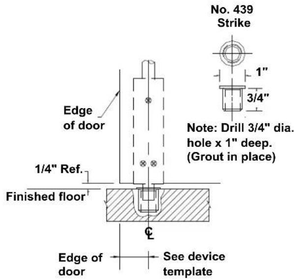
 | #439 Bottom Strike (Cement or Grout In Place) | |
 | (10) 8-32 x 3/8" F.H.P.M.S. Chassis Cover, End Cap & Latch Covers | |
HANDING OF DOOR

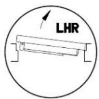

Read the entire instruction sheet prior to installation. Before Installing Hardware:
- Verify door width, handing and product with carton label for correct exit device and length. (See Step 7).
- For hand reversal of chassis see (step 4), for outside lever trim see (step 5).
- For less bottom rod device, delete bottom latch installation steps.
Note: Less bottom rod device is not recommended where security is a primary concern.
Note: If device is to be installed over glass lite panels, shim kit may be required, order GK9000.
Note: Device shipped standard for 7' high door opening. Optional 8' available. (must be specified when ordering) For doors up to but not over 10' order "ETR" (Extended top rod) package.
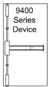
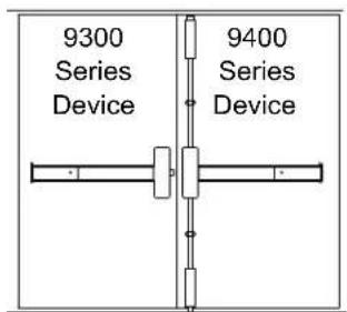
TYPICAL APPLICATIONS





SPECIAL TOOLS FOR INSTALLATION
12-24 Tap, 10-32 Tap
Drill bits: 1/8", #25, #16, #21 & 3/8"
Hole saws: 1", 1 1/4", & 2 1/8" diameter for trim (if required).
Jig saw or router may be required for thumbpiece trims.
5/32" Allen wrench for lever trim.
1
With door lying on saw horses, open box, layout all parts and verify prior to starting installation. See page (1) one for parts.
2
Door preparation

Finished floor, if using threshold measure from top of threshold.
Chassis template located at rear of booklet. Cut and tape in place. Lay out horizontal and vertical reference lines.

Backset or vertical reference is measured from outer edge of door as shown.
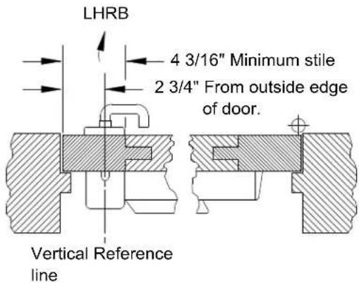


| Minimum vertical ref. of chassis | Minimum Stile | ||
| Type of installation | No trim | Trim | |
| Single door 1/2" blade stop | 2 3/4" | 4 3/16" | 4 3/16" |
| Pairs and double egress | 2 3/4" | 4 3/16" | 4 3/16" |
| Paired with 9300 rim | 2 1/2" | 4" | 4" |
| Paired with 9500 mortise | 2 3/4" | 4 3/16" | 4 3/16" |
3
Hang door(s) in opening, ensure they are square and plumb.
4
If hand reversal of chassis is required follow steps below in alphabetical sequence.

5
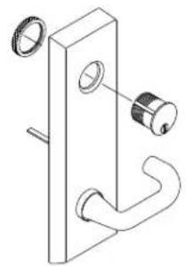
Handing change of trim, and cylinder specifications and installation.
Note: For specific trim function, cylinder type or handing information see additional instructions packed with trim.

Standard "Y" Trim
natural_image
Technical line drawing of a door handle with two circular components and a curved handle (no text or symbols)Standard "V" Trim

natural_image
Technical line drawing of a door handle with a key inserted (no text or symbols)Standard "T" Trim
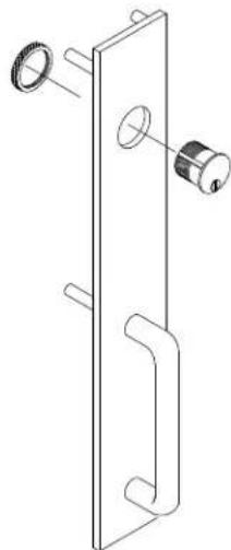
natural_image
Technical line drawing of a door handle assembly with mounting holes and a key (no text or symbols)Standard "R" Trim

Standard "C" Trim

Standard "K" Trim
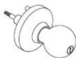

All trims are free wheeling. (Handle will rotate when locked.)
IMPORTANT
Note: All lever handles except for "clutch" are shipped unattached. To install; Place handle in desired position and attach with allen screw located in bcak of trim plate. 5/32" Allen wrench required. To change hand on "clutch" trim rotate and "break" lever around to desired hand.

Spindle must be installed with drive pin in vertical position as shown.
6
If not done layout device on door using drilling template T9400 located at rear of booklet. For additional templates contact DORMA at 1-800-523-8483 or www.dorma-usa.com
Refer to carton label for model and trim number prior to drilling. Prepare mounting holes and cut-outs per template.

7
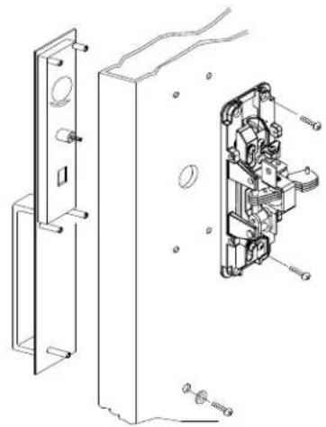
Secure chassis to door per below, if using GK9000, install shims under chassis at this time.
Metal - (2) 12-24 x 1 1/2" F.H.P.M.S.
Wood - (2) #12 x 1 1/4" F.H.P.T.S.
(For other options; trim, thru bolts, etc. see below.)

natural_image
Technical line drawing of a mechanical assembly with internal components and mounting brackets (no text or symbols)8
Prepare to install touch and rail on door.
NOTE: All dimensions are based on 5/8" stop height; Verify strikes, stile width, any trim and stop height prior to making any cuts. If cutting is required follow instructions below.
Size A:
Fits 48" door opening without cutting.
Can be cut to fit a 34" minimum door opening.
Size B:
Fits 36" door opening without cutting.
Can be cut to fit a 28" minimum door opening.
Size C:
Fits 36" door opening with out cutting.
Using a shorter touch pad then the standard "B" size allows it to be cut to 25" door opening.
Note: Models with prefix options such as "ES", "DE" etc. may not be cut down to minimums shown to left. Consult factory or catalog for details.
NOTE: If carton label list prefix; "ES", "MS", "LM", "BPA", "BPAR", "DWA", "LM/MS/BP" or "CD" prefix see Options pages at rear.
Verify device length with box label; "A", "B" or "C", ie. 9300B

IMPORTANT
Use caution when cutting touchbar and rail to size on models with "ES", "MS", "LM" or "DWA" prefix options. These units contain internal wiring.
For models with prefix options "BPA", BPAR" or "DE" remove filler containing electronics before cutting.
Note: If door opening width is less then standard touch bar will have to be cut down. ie: door opening width 34" subtract 2" from rear of touch bar and rail, tape and cut to length as shown.

9
Install touch bar and rail assembly and end cap bracket to door.
Remove two 8-32 screws from chassis, slide touch bar and rail assembly under rear of chassis. Note: If device has prefix "ES" ensure that pins in lever bolt align with slots in actuator located inside nose of touch bar. See instruction sheet IES-7 packed with device. Install (2) two 8-32 x 3/8" P.H.P.M.S. to secure touchbar to chassis.
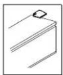
Hold rear mounting bracket tightly against door and rear of rail. Mark (2) two holes and drill per chart. Secure with proper fasteners.

(2) 8-32 x 3/8" P.H.P.M.S.
"Remove protective covering from the touchbar and rail assembly prior to installing on door."

Metal/thru-bolts - (2) 12-24 x 1" F.H.P.M.S. Wood - (2) #12 x 1 1/4" F.H.P.T.S.
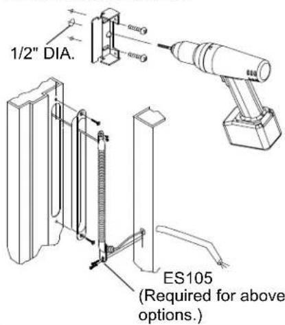
For the following models prefixes: "ES", "MS", "LM" or "DWA" drill an additional 1/2" diameter hole as shown. See options pages at rear for additional information.
10
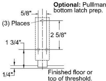
Prop door open and layout and prep top and bottom latch case locations. Templates located at rear of booklet, tear out, cut and tape to door as shown, mark and drill per chart.

natural_image
Technical line drawing of mechanical assembly with tool and component views (no text or symbols)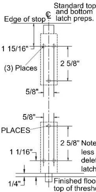


Metal/thru-bolts - (2) 12-24 x 1" F.H.P.M.S. Wood - (2) #12 x 1 1/4" F.H.P.T.S.

11
Install top and bottom latch case assemblies.
Inter-locking strike angle for fire rated doors over 8' and all fire rated LBR (less bottom rod) devices.
Mount behind latch assembly.
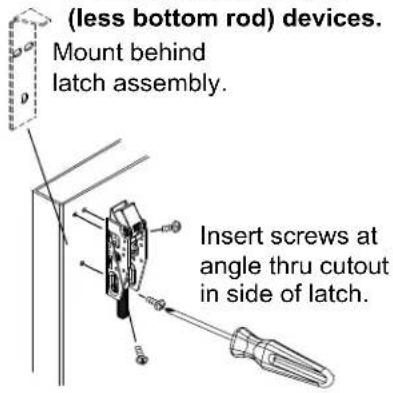
—No. 12 x 1" R.H.P.T.S. (Wood)
-12-24 x 1/2" R.H.P.M.S. (Metal)
-12-24 x 1 1/4" R.H.P. M.S. (Thru bolts)

Required for; "LBR" (less bottom rod) fire rated exit devices.
See additional instructions packaged with "Popper" for details.

12 Install top rod and adjust top latch.

Rods shipped cut to length for 7' door opening. Optional 8' door opening available, (must be requested at time of ordering). For doors over 8' and up to 10' request "ETR" package at time of ordering. For top rod length other than "standard" see chart below. Order 8' option and cut to length.
Depress tripping lever and ensure that top latch is fully extended and in dead locked position. Bolt should
not be able to be depressed. Bell-crank of chassis should be completely down in home position.
Thread top rod onto adjusting bolt until hole in bottom of rod aligns with hole in rear of top portion of bellcrank. Insert leg of retaining plate through hole in rod and hole in bellcrank, install 8-32 x 1/2" screw and tighten securely.
7' Standard 8' Optional Top Rod Top Rod

NOTE:
If horizontal reference line is moved from the recommended mounting height, new rods may have to be ordered.
If cutting is required "Do Not Cut Threaded End". (See Chart)
Use supplied drill jig and 1/8" drill bit if new hole is required.
| DOOR HEIGHT | TOP ROD LENGTH |
| 6'8" | 31 1/4" |
| 6'10" | 33 1/4" |
| 7'0" | 35 1/4" |
| 7'2" | 37 1/4" |
| 7'4" | 39 1/4" |
| 7'6" | 41 1/4" |
| 7'8" | 43 1/4" |
| 7'10" | 45 1/4" |
| 8'0" | 47 1/4" |
13 Check for proper function of device and top latch assembly.

natural_image
Technical line drawing of a mechanical assembly with mounting bracket and clamping mechanism (no text or symbols)Depress touch bar slowly, top latch bolt should retract fully. Hold bar depressed, push in and hold top tripping lever. Latch bolt should be flush or slightly depress in top latch case.
If this is found, release touch bar and tripping lever top latch bolt should remain captured by tripping lever.
Push in on tripping lever and release top latch bolt, bellcrank should drop completely down and top latch should be fully extended and dead locked. (You should not be able to push the bolt in.)
If top bolt does not retract fully or can be pushed in, adjustment of top rod is required: Remove 8-32 screw and retaining plate; rotate rod left (clock-wise) to lengthen, half turns at a time. Re-install retaining plate and screw; check for dead lock after each turn.

natural_image
Hand inserting a component into a vertical panel, showing mechanical assembly (no text or symbols)
14 Install top strike. See spotting templates located in rear of booklet if not already done. Check for proper alignment and operation with top latch after installation.


15 Installation of bottom slide bolt or latch assembly.

NOTE:
If horizontal reference line is moved from the recommended mounting height, new rods may have to be ordered.
If cutting is required "Do Not Cut Threaded End".
Use supplied drill jig and 1/8" drill bit if new hole is required.
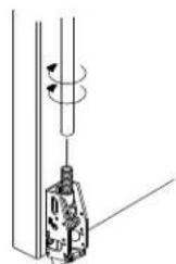
Thread bottom rod approximately 1/2 way on to slide bolt assembly.
With bell crank down and top latch fully extended and dead locked.
Insert rod and slide bolt assembly in to bottom latch bracket as shown, rotate rod until hole in rod aligns with hole in bell crank. Insert retaining clip and secure with 8-32 x 1/2" screw.
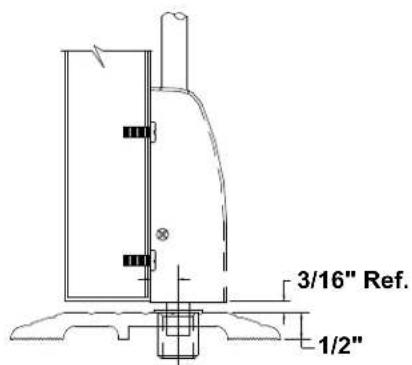
Check to see that there is approximately 5/8" of bolt hanging down and that bolt moves up and down freely in latch case.

natural_image
Diagram of a mechanical device with rotating arm and connecting rod (no text or symbols)With bell crank down and top latch fully extended and dead locked.
For optional pullman latch: Thread rod approximately 1/2 way on to adjusting bolt, tilt rod upward, rotate rod clock-wise to shorten, counter clock-wise lengthen until hole in rod aligns with hole in bell crank. Bolt should be dead locked when down just as top bolt. Adjust rod until dead lock is achieved.
16 Installation of standard bottom strike. For additional strike installations see templates in rear of booklet.

17
Verification of rod adjustments.

A. Block open door, push inward on tripping lever and release top latch bolt to ensure it is fully extended.
Top latch should be fully extend and dead latched as shown and bell crank should drop completely down.


B.
Check for dead lock by attempting to push downward on top latch bolt (it should not push in). "Only" if it can be pushed in adjust rods per step below.
C. To adjust: Remove 8-32 screw, remove retaining plate, rotate top rod right (counter clock-wise) to shorten and left (clock-wise) to lengthen. Rotate half turns at time, re-install retaining plate and screw after each turn and check for dead lock of top latch bolt.
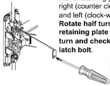

natural_image
Mechanical assembly diagram showing a tool inserted into a housing (no text or labels visible)Flush

D. Depress and hold touch bar. Push in on tripping lever and hold depressed, check position of top latch bolt. It should be flush to slightly depressed in top latch bracket.
E. Release tripping lever and touch bar, top latch should remain in retracted position
Slide bolt clears strike

F. With top latch held retracted by tripping lever, check bottom slide bolt to ensure it clears the strike, threshold, and floor by unblocking and swinging door. If adjustment is required; follow same steps as in step C above for top rod until proper clearance is achieved.
G. Close door and check that top and bottom latch bolts align and engage in top and bottom strikes.
H. After rods are fully adjusted ensure that top and bottom rod retaining plate screws are tight.
I. Check device operation by opening and closing door several times from inside. Check and operate outside trim if installed.
Repeat rod adjustment procedure if:
Top latch is not held retracted Bottom slide bolt does not clear strike or floor. Latches do not work properly with outside trim
J. Install rod guides, end cap, center case and latch covers.

K. Standard hex key dogging, depress touch bar insert supplied hex key and rotate clock wise to dog and counter clock wise to undog.

OPTIONAL: BOTTOM STRIKE PREPARATION
416 Strike
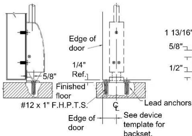
For surface strike drill (2) 5/16" diameter x 1" deep holes for anchors.


431 Strike

Drill (2) 3/8" dia. holes x 2" deep for anchors.
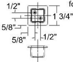
Note: 1 15/16" min. to 1 5/8" max. square cutout x 1" deep.
340 Strike
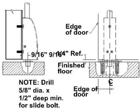

For surface strike; drill (2) 5/16" dia. x 1" deep for anchors.
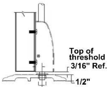
ROD CUTTING

NOTE: Rods shipped standard from factory for 7' seven foot door opening.
Optional rod pack for 8' eight foot openings available "must be noted at time of order".
For doors under 7' seven foot subtract difference from bottom of top rod, cut per details and redrill hole for retaining plate.
For doors over 7' seven foot but under 9' nine foot a 2' two foot rod extension "ETR" is available. Thread top rod and rod extension together, deduct difference, cut from bottom of top rod and redrill hole for retaining plate. "Do not cut rod extension".
For doors over 8' eight foot but under 10' ten foot the 2' two foot rod extension "ETR" is added to the 8' eight foot rod pack. Thread top rod and rod extension together, deduct difference, cut from bottom of top rod and redrill hole for retaining plate. "Do not cut rod extension".
NOTE:
If horizontal reference line is moved from the recommended 40 5/16" height, new rods will have to be ordered.

"Do not cut threaded end"

11/64" Dia. Drill Thru, use small hole in guide.
INSTALLING ROD EXTENSION
POPPER DETAILS
For "ETR" (Extended Top Rod) devices. *Do not cut extension piece!
Connecting link
Thread rods together securely. "Loc-tite may be used for added security".
Standard top rod
Required for; "LBR" (less bottom rod) are rated exit devices
See additional instructions packaged with "Popper" for details.

OPTIONS
"CD" (CYLINDER DOGGING) OPTION:
Cylinder dogging installation instructions & cylinder specifications.
NOTE: Touch bar must be in dogged down position, to remove the rear filler panel.
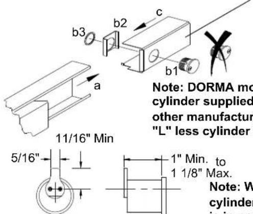
Useable Cams
Arrow 001
Assa Std. (Yale)
Best C136
Corbin A02
Falcon 12667-3
DORMA 10
Ilco/Unican SC1
Lori SC1 4200-82-2002 Std.
Sargent 13-0664 or 13-0660
Schlage 001
Yale 2160
Note: When using IC core cylinders, ensure that cam is in proper position prior to installing the new core.
Witness Marks

Correct

In-correct
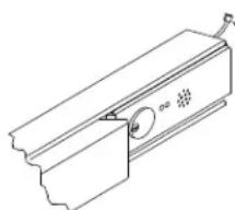
"BPA" & "BPAR" ALARM OPTION: (STANDARD INSTALLATION)
BPA: Battery powered alarm, sounds continuous or until disarmed.
BPAR: Battery powered alarm, sounds for 4 minutes, automatically resets.
"Alarm mode set at factory."
"LM" LATCH MONITOR OPTION:
Latch monitor: Monitors movement of latch bolt, with or without depressing of touch bar.
Can be wired normally open or normally closed.
NOTE: Touch bar must be in dogged down position, to remove the rear filler panel.
*NOTE: Use caution when cutting touch bar and rail to length.
SIZE A:
Will fit 48" (1219 mm) door opening without cutting.
Can be cut to fit a 39" (991 mm) minimum door opening.
SIZE B:
Will fit 36" (914 mm) door opening without cutting.
Can be cut to fit a 33" (838 mm) minimum door opening.
SIZE C:
Will fit 36" (914 mm) door opening without cutting.
Can be cut to fit a 30" (762 mm) minimum door opening.
*NOTE: Use caution when cutting touch bar and rail to length.
NOTE: Touch bar must be in dogged down position, to remove the rear filler panel.

(DORMA mortise cylinder supplied.) 90B10SC118
To install customer supplied cylinder, see cylinder dogging option at top of page.
12-24 x 3/4" R.H.P.M.S.
To replace battery remove endcap.
Refer to additional alarm instructions packed with device for operation of alarmed exit device.
OPTIONS
"ES" ELECTRIC LATCH RETRACTION OPTION:
Electrically retracts latchbolt(s) when energized by power supply.
REQUIRES DORMA PS-501 POWER SUPPLY, WILL NOT OPERATE FROM OTHER MANUFACTURES POWER SUPPLIES.
PS-501 Will operate (2) "ES" 9400 exit devices. By adding a second "ES2" logic card, (2) additional "ES" 9400 exit devices may be used.
*NOTE: Use caution when cutting touch bar and rail to length.

"DWA" DIRECT WIRED ALARM OPTION:
Connected to outside power source.
12-24 Volt AC/DC Power Supply.
i.e. DORMA ES-100.
Contact DORMA for other power supplies available.
NOTE: Touch bar must be in dogged down position, to remove the rear filler panel.
8-32 x 3/8" F.H.P.U.C.M.S.
DWA
Battery Eliminator

*NOTE: Use caution when cutting touch bar and rail to length.
natural_image
Technical line drawing of a mechanical component with a circular feature and mounting bracket (no text or symbols)(DORMA mortise cylinder supplied.) 90B10SC118

12-24 x 3/4" R.H.P.M.S.
Refer to additional sheet IAL9000 packed with device for operation of alarmed exit device.
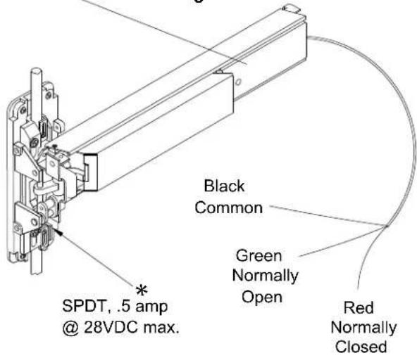
"MS" MICRO SWITCH OPTION:
"MS" option allows monitoring of touch bar during normal operation, or can be used as a signal switch for horn, light etc. Come standard with
(2) two micro switches. Both can be wired either Normally Open or Normally Closed. Can be added to device after installation.
Note: Normal switch position shown, once installed normally open and closed positions are reversed.

"MD" MAGNETIC DOGGING OPTION:
Electrically dogs touch bar when energized by power supply, then depressed. Releases upon interruption of power.
.25 AMP CURRENT DRAW @ 24VDC
REQUIRES DORMA PS-545 POWER SUPPLY CAPABLE OF POWERING 1 - 4 "MD" DEVICES. THE USE OF A POWER TRANSFER, ES105 OR AN ELECTRIC HINGE PTH-2 IS RECOMMENDED.
FITS "STANDARD" TOUCH BAR AND RAIL ASSEMBLIES ON BOTH THE 5000 AND 9000 SERIES EXIT DEVICES. NOT AVAILABLE ON DEVICES SUCH AS "ES", "DE", "AL", BPA. BPAR, DWA, DWRA ETC.
MAXIMUM HOLDING FORCE 40# - 60#. IMMEDIATE RELEASE UPON REMOVAL OF POWER.

| Maximum Wire Length From Power Supply To Device & Back To Supply In Feet x Wire Gage/Size * | ||||
| WIRE | 18AWG | 16AWG | 14AWG | 12AWG |
| FEET | 25 | 50 | 75 | 100 |
* For wiring to electric hinge or power transfer.
Black Negative Positive
*NOTE: Use caution when cutting touch bar and rail to length.



OUTSIDE DOOR PREPINSIDE DOOR PREF
(VERTICAL REFERENCE) (VERTICAL REFERENCE)

T9400 5/2011
- HANDING OF DOOR
- TYPICAL APPLICATIONS
- SPECIAL TOOLS FOR INSTALLATION
- 1
- 2
- 3
- IMPORTANT
- 6
- 7
- 8
- Size A:
- Size B:
- Size C:
- 9
- 10
- 11
- NOTE:
- Check for proper function of device and top latch assembly.
- Install top strike. See spotting templates located in rear of booklet if not already done. Check for proper alignment and operation with top latch after installation.
- Installation of bottom slide bolt or latch assembly.
- With bell crank down and top latch fully extended and dead locked.
- Installation of standard bottom strike. For additional strike installations see templates in rear of booklet.
- 17
- Verification of rod adjustments.
- B.
- Flush
- Slide bolt clears strike
- Repeat rod adjustment procedure if:
- OPTIONAL: BOTTOM STRIKE PREPARATION
- Strike
- Strike
- Strike
- ROD CUTTING
- INSTALLING ROD EXTENSION
- POPPER DETAILS
- OPTIONS
- "CD" (CYLINDER DOGGING) OPTION:
- "BPA" & "BPAR" ALARM OPTION: (STANDARD INSTALLATION)
- "LM" LATCH MONITOR OPTION:
- "ES" ELECTRIC LATCH RETRACTION OPTION:
- "DWA" DIRECT WIRED ALARM OPTION:
- "MS" MICRO SWITCH OPTION:
- "MD" MAGNETIC DOGGING OPTION:
Brand : Dormakaba
Model : 9400
Category : Door security system