
GWI 2120B - Interface de communication GSM Vemer - Free user manual and instructions
Find the device manual for free GWI 2120B Vemer in PDF.


| Product Type | GSM Communication Interface |
| Brand | Vemer |
| Model | GWI 2120B |
| Dimensions (Width x Height x Depth) | 4 DIN modules (approx. 70 x 90 x 60 mm) |
| Weight | Approx. 200 g |
| Power Supply | 15–40 V DC / 11–28 V AC 50 Hz |
| Power Consumption | 100 mA max |
| GSM Module | Quad Band (900/950/1800/1900 MHz) |
| Relay Outputs | 1 bistable relay (change-over, 8A/250V AC) + 1 normally open relay (5A/250V AC) |
| Digital Inputs | 2 (max 40 V DC, impedance 10 kΩ) |
| Analog Input | 1 (0–10 V or 0–20 mA, impedance 100 kΩ) |
| Auxiliary Power Output | Rectified from supply (max 25 mA) |
| Number of Programmable Phone Numbers | Up to 60 (including up to 10 for alarm contacts) |
| Backup Battery | 1 hour capacity |
| Operating Temperature | 0 to +50 °C |
| Storage Temperature | -10 to +65 °C |
| Humidity | 10–90% non-condensing |
| Protection Degree | IP40 |
| Insulation Class | II |
| Safety Standards | EN 60950-1, EN 301489-1/7, EN 61010-1 (Cat III, PD 2) |
| Main Functions | Remote control via SMS/ring, alarm monitoring, pulse/time counting, analog measurement, scheduled SMS |
| Installation | DIN rail mount, requires qualified electrician |
| Accessories Included | External antenna with 3 m cable, SIM card slot (push-push) |
| Programming | Via SMS commands or USB port (mini-B) to PC |
| Maintenance | No user-serviceable parts; contact after-sales for faults |
Frequently Asked Questions - GWI 2120B Vemer
User questions about GWI 2120B Vemer
0 question about this device. Answer the ones you know or ask your own.
Ask a new question about this device
Download the instructions for your Interface de communication GSM in PDF format for free! Find your manual GWI 2120B - Vemer and take your electronic device back in hand. On this page are published all the documents necessary for the use of your device. GWI 2120B by Vemer.
USER MANUAL GWI 2120B Vemer
CE
GSM communication interface: User Manual
Indice
natural_image
Line drawing of an electronic device with a paper clip inserted into the base panel (no text or symbols)• Gestione sim card (solo admin)
OUTALARM 2 OFF DIG2 MAN
Turn on/off and reset device Page 37
Commands to the instrument Page 38
Managing digital inputs
Analog input management
Alarm management
■ GWI 2120B programming via PC
■ Reference standards
Page 44
Page 48
Page 51
Page 54
Page 55
DIMENSIONS


DEFAULT SETTING
| Password 12345678 | |
| Relay output status Off | |
| ADMIN number Not defined | |
| USER numbers Not defined | |
| STAFF numbers Not defined | |
| Analog input 0-10V | |
| Alarm from digital inputs Active | |
| Alarm from analog input Disabled | |
| Caller control Active | |
| Response to ring command Disabled | |
| Response to sms commands Active | |
| Forward unknown sms Active | |
| Advise power fail Active |
CONNECTION DIAGRAMS

flowchart
graph TD
    A["Alimentazione"] --> B["1"]
    A --> C["2"]
    B --> D["Out 2 2 0"]
    C --> E["Out 1 2 0"]
    D --> F["4"]
    E --> G["6"]
    F --> H["7"]
    G --> I["8"]
    H --> J["9"]
    I --> K["In 1 In 2"]
    J --> L["In 1 In 2"]
    K --> M["10"]
    K --> N["11"]
    M --> O["-"]
    N --> P["+"]
    O --> Q["12"]
    P --> R["13"]
    Q --> S["14"]
    R --> T["+"]
    S --> U["+"]
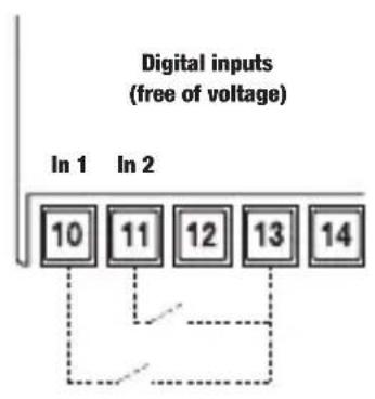

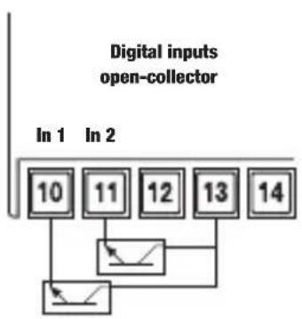
flowchart
graph TD
    A["10"] --> B["In 1"]
    C["11"] --> D["In 2"]
    E["12"] --> F["In 2"]
    G["13"] --> H["In 2"]
    I["14"] --> J["In 2"]
    B --> K["Output"]
    D --> L["Output"]
    F --> M["Output"]
    H --> N["Output"]
    J --> O["Output"]

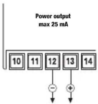
The communication interface GWI 2120B is an electronic device in a container 4 DIN modules that perform 1B type actions based on GSM technology that allows remote management of utilities thanks to the two output relays that can be controlled by sending an SMS or ring phone. The two digital inputs, along with analog, also allow monitoring for danger, thus allowing the intervention automatic, with the times and modes. Any alarms or changes in status of inputs can be reported by sending an SMS or a phone ringing one or more numbers selected. The GWI 2120B also features a battery that allows the instrument to operate for about an hour even in the absence of power to send an alarm Mains electricity.
SAFETY WARNINGS
■ During the installation and operation of the device observe the following instructions:
1) The instrument must be installed by a qualified person
2) The instrument must be installed and activated in compliance with current electric systems standards
3) After installation, inaccessibility to the connection terminals without appropriate tools must be granted
4) Do not use the instrument for purposes other than indicated
5) The device must be installed in a electric closed panel well protected
6) A two-pole disconnect device shall be provided as part of the building installation
7) A protection device against over-currents should be installed in the electrical system, upstream of the device
8) Carefully respect the wiring diagrams to install the instrument
9) Before accessing the connection terminals, verify that the leads are not live
10) Do not power or connect the instrument if any part of it is damaged
11) The use of a GSM device can cause interference with the functioning of electronic devices non-screened from radiofrequency signals (electromedical devices, pacemakers, hearing aids etc.)
12) In case of fault, do not service the device yourself but contact the after-sales service
13) The instrument is aimed for use in place with measurement category III and pollution degree 2, as per standards EN 61010-1.
TECHNICAL CHARACTERISTICS
• Power supply: 15÷40V dc / 11÷28V ac 50Hz
• Absorption: 100mA max
- Digital input:
– Maximum voltage applicable to the digital inputs: 40Vdc
– Maximum voltage for logic level low: 4Vdc
– Minimum voltage for logic level high: 5Vdc
– Digital input impedance: 10 kΩ
- Analog input
– Maximum voltage applicable to the digital input: 11Vdc
– Live analog input impedance: 100 kΩ
– Maximum current applicable to the analog input: 25 mA
- Output
- n. 1 bistable relay with change-over contact and breaking capacity: 8A / 250V AC
- n. 1 normally open relay and breaking capacity: 5A / 250V AC
- Auxiliary power output(Vout terminals 12-13) rectified dipping of power supply (Vin terminals 1-2))
Example: Vin=15V de Vout=13.5V dc Vin=12V ac → Vout=15.5V dc
Vin=24V dc → Vout=22.5V dc Vin=24V ac → Vout=32.5V dc
- Signalling LEDs:
- Two red LEDs for output relay status signalling
- Two green LEDs for digital input status signalling
– Multicolor LED for device status signalling
• GSM Quad Band module (900-950-1800-1900 MHz)
• SMA-F connector for external antenna provided with 3 m long cable
• USB port (mini B type) to connect with Personal Computer (cable not included)
- Possibility to enable 60 numbers which 10 for sending alarms (contact numbers)
• Operating temperature: 0 ÷ 50 °C
• Operating humidity: 10 ÷ 90% noncondensing
• Storage temperature: -10 ÷ +65 °C
• Degree of protection: IP40
- Insulation: class 中
- Container: 4 DIN modules
• Backup battery capacity: 1 hour
DEVICE STATUS
The status of the device is segnalated by the led :
OFF → system not fed
BLINKING RED sim not inserted or pin code in activity
FIXED RED GSM field insufficient
FIXED GREEN→ starting system/network research
BLINKING GREEN connected to GSM network
QUICKLY BLINKING GREEN → arriving in command (ring or sms)
QUICKLY BLINKING RED/GREEN → programming mode active
BLINKING YELLOW connected to gsm field but low level battery
QUICKLY BLINKING RED → modem error or failure (if still flashing)
Note: blinking = 1 lamp / second
quickly blinking = 5 lamps / second
INSTALLATION
Getting a sim card enabled for phone traffic, with the required pin code and the answering machine disabled (to disable the pin code, to use a mobile phone and follow the steps described in the relative user's guide).
Remove the flip cover of the housing using a screwdriver.
Insert the sim card into the slot (push-push type). The direction of insertion provides that the bevel of the sim card goes inside in the left.
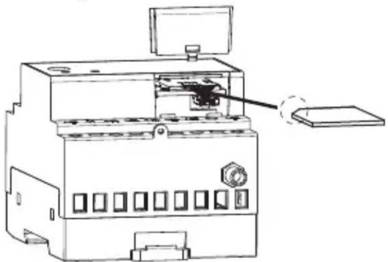
natural_image
Technical line drawing of a mechanical device with an attached component (no text or symbols visible)Note: ensure that the power cables are disconnected before inserting/remove the sim card.
Fix the cover
Screw the supplied antenna into its connector on the side of the instrument.
Note: Ensure that the power cables are disconnected before replace the antenna.
Connect the power and the load as shown in the “wiring diagrams”. Once the instrument has been connected, the led 📋 will remain green fix for about 30 seconds; then the led 📋 begins to blinking once at second, indicating the correct reception of the gsm network. If this is not the case, see box “Device status” pag. 34.
STORE ADMIN NUMBER
For the proper functioning of the instrument it is necessary to set the number admin who has full control of the instrument.
The first number to make a ring after the first start (or after a reset of the instrument) will be stored as number admin.
- hold the "1-SET" button for 5 seconds until the led 📋 begins to flash alternately red / green
- make a ring with the number you want to set as many admins.
The caller will receive an sms confirmation of activation.
MANAGEMENT ENABLED NUMBERS
• Managing user numbers
You can create a phone book containing up to 60 phone numbers (user numbers) the which may act on the state of relay by sending sms or phone rings.
There are two ways to add a user number:
- via phone ring
Hold for 5 seconds the "Set" button until the led begins to flash alternating red / green.
Make a ring with the number concerned. This number will be inserted (removed) from the list of user if not present (present) in the phonebook. An sms confirmation will be sent to caller with an indication of the phrases employed total available.
- via Sms
The number admin can add or remove at any time the user numbers by sending the following commands :
USERADD [list of numbers to be added] USERDEL [list of numbers to be removed]
Numbers add / remove should be separated from each other by a empty space.
• Edit number admin (for admin only)
The admin number can be changed by sending (from the current admin number) the following command:
ADMIN [new admin number]
The new admin will receive an sms number to confirm your transaction.
Note. If the number admin is lost, you can change only forcing a reset, losing all the numbers previously enabled. For avoid having to reload manually, please refer to “Manage sim card” pag. 37.
- Set-up for contacts
By using the STAFF command it is possible to enter up to 10 telephone numbers with an index from 1 to 10 and used for sending alarm signals (see management of the alarms).
STAFF without parameters → displaying saved numbers
STAFF [index][telephone number]...[index][telephone number] → insertion / cancellation staff numbers (cancellation using “NULL” string)
To enter a STAFF number at position 4:
STAFF 4 392123445
It is also possible to enter several STAFF numbers using one command only:
STAFF 1 392123445 2 043980638 6 12334455
in this case the numbers in positions 1, 2 and 6 are entered. If there is already a STAFF number it will be overwritten.
To cancel a STAFF number, write NULL in the place of the number for example
STAFF 1 NULL → cancels the STAFF number at position 1
The response to a STAFF command is always the whole STAFF directory in the following format:
STAFF 1=333800123 2=NULL 3=NULL 4=NULL 5=NULL 6=NULL 7=NULL 8=NULL 9=NULL 10=NULL
If the number is NULL the contact is not defined..
NB: the number ADMIN is entered by default as STAFF with index 1. In the case of adding a STAFF number which does not appear among the enabled numbers (user), this will be also be automatically added in the user list.
- Manage SIM card (for admin only)
The enabled telephone numbers are saved in the memory of the device. In case of reset, this implies the loss of all the enabled utilities. To avoid having to re-enter all the numbers manually, it is possible to make a backup copy of the sim card through the following commands, to be given by the administrator only:
STORE creates a copy in the sim card of all the saved user numbers
RESTORE only restores the numbers previously saved with STORE
Therefore, once all the telephone utilities have been enabled, it is advisable to make a backup of the phone book.
• Display stored user (for admin only)
To see all the saved numbers, use the command
USERVIEW [start], where [start] indicates the first memory location to be displayed
The numbers will be displayed in blocks of 8. A possible response on the USERVIEW 3 command is:
USERVIEW(3-10)=333123455(1) 392234543 0439879832 (3/64)
Number (1) next to the first number indicates that that number is also a staff number and is in the first position.
OPERATION
TURN ON/OFF AND RESET DEVICE
• Turn off the instrument:
Hold approximately 10 seconds for either the "1-SET" or "2" until all LEDs off. During the pression of the key, the output led blinks quickly and the led blinks green (or yellow) for the first 5 seconds and green/red for the other 5 seconds.
• Turn on the instrument without reset
➢ Press “2”. The LED will be green initially fixed and then begin to flashing green (or yellow), indicating the correct reception of the GSM signal.
• Turn on the instrument with reset
➢ Press the “1-SET”. The input and output leds will illuminate for a few seconds; waiting for they go out and press “1-SET” key. The LEDs will flash simultaneously a pair of times indicating that the reset occurred.
Note: The reset erases all data, settings and users stored tool and restore factory defaults (see box on).
COMMANDS TO THE INSTRUMENT
The two relay outputs can be piloted in the following ways:
– with the keys on the front panel
— via ring or text message from an enabled number
– following an alarm in one of the inputs present
Commands from ring or text message
The outputs can be commanded from a distance via a text message or a telephone ring. The structure of a text message is as follows:
[password] [separator] [command] [parameter1] [separator]..[parameterN] where:
[password] → numerical field of a maximum of 8 figures
[separator] → comprised of one or more space characters
[command] → command recognised by the device
[parameter] → series of parameters relative to the command
The password field may be omitted if the command is given by qualified number. Several commands may be included in one text message. In this case, the commands executed will only be those whose reply is contained in a standard text message (160 characters). To enter numbers with the decimal separator, you need to use a full stop.
The structure of a reply to a command is similar to the command itself, with the addition of the “=” symbol to indicate the current status. For example:
• Set operation mode button (for admin only)
A quick press of the button allows it to act on the output.
To define the mode of behavior output using the command:
OUTKEY [functionality] with functionality that can assume the values:
- RING it reacts as it does to a call when the key is pressed
- TOGGLE the key switches the output ON/OFF in bistable mode
- BLOG® disables the key functionality (it is not possible to access programming mode when in this mode)
If the value is omitted, the current instrument status will be the response.
The default setting is RING.
- Caller control activation/deactivation (for admin only)
The caller number control can be disabled if you wish to temporarily allow anyone to command the outputs via the command:
RINGCONTROL [status] with status that can assume the values:
- OR activates a control of the caller to check it is enabled
- OFF disables the caller control function
If the value is omitted, the current instrument status will be the reply.
• Activation/deactivation of a text message of reply to a ring (for admin only)
A function can be activated to receive a text message following a ring, containing the response of the instrument upon receiving the call with the command:
RINGRISP [status] with status that can assume the values:
- OR sends a text message to the caller on the response of the outputs to the ring
- OFF no text message will be sent as reply
If the value is omitted, the current instrument status will be the reply.
• Defining the response to a ring (for admin only)
The response of the outputs to a ring from an enabled telephone number can be defined through the command:
OUTRING [output number][output status][status holding time][unit of measurement], where
- [output number] → indicates the output to which reference is made (1 or 2)
- [output status] → can assume the values ON, OFF, TOGGLE, DISABLE
- [status holding time] → maximum time setting (2 2 -1) secondi (parametro opzionale)
- [unit of measurement] → s seconds, m minutes, h hours (optional parameter)
Some examples:
OUTRING 1 ON the relay 1 is turned ON
OUTRING 1 OFF 10 S the relay 1 is turned OFF for 10 seconds when the ring is received
OUTRING 2 DISABLE the relay 2 does not do anything when the ring is received
OUTRING 2 TOGGLE the relay 2 changes position when the ring is received
- Setting the output status
To send more complex commands to the instrument, text messages must be used. The possible commands are:
OUT [output number][output status][status holding time][unit of measurement], where
- [output number] → indicates the output to which reference is made (1 or 2)
- [output status] → can assume the values ON, OFF
- [status holding time] → maximum time setting (2-1) seconds (optional parameter)
- [unit of measurement] → s seconds, m minutes, h hours (optional parameter)
Some examples:
OUT 1 OFF 10 S sets the relay 1 OFF for 10 seconds
OUT 2 ON 12 H sets the relay 2 ON for 12 hours
- Setting the text message forwarding to the sender (for admin only)
The instrument can be set to send the sender a text message of confirmation upon receiving a command via a text message. The command is
OUTRISP [status] with status that can assume the values:
- 0 enables the sending of a text message of reply to the sender
- OFF disables the sending of a text message of reply to the sender
If the status is omitted, the reply will be the current instrument status.
- Setting display
The device can be queried to know the relevant configuration, using the command:
OUTINFO
Here is an example of a possible reply:
OUT 1=ON OUTRING= ON 5S OUT 2=OFF OUTRING=ON 2S OUTRISP=ON
RINGRISP=ON OUTKEY=RING
meaning:
output 1 on, response to a ring on for 5 seconds, output 2 off, response to a ring on for 2 seconds, reply to text messages enabled, reply to a ring enabled, reaction to pressing a key the same as to a ring
• Modifying output names (for admin only)
To assign a name to the output that recalls the device to which it is connected, use the command:
OUTTXT [output number] [output label]
Some examples:
OUTTXT 1 port assigns output 1 the name port
OUTTXT 2 valve assigns output 2 the name valve
OUTTXT 2 NO restore the original name to output 2
A string of a maximum of 10 characters with no spaces can be assigned as a name. To restore the original name, just write OUTTXT NO. If an alternative number for an output is defined, it is possible to use this name to indicate the output in the transmitted commands. For example:
valve ON 10 M activates output 2 (valve) for 10 minutes
• Enabling the forwarding function (for admin only)
The instrument can be set to redirect to a specified number all the text messages it receives and does not recognise as commands.
The command is:
FORWARD [number]
If not modified, the number that receive the unknown sms is the admin. FORWARD OFF
disables the function.
The text message that the specified number receives begins with "FW:".
• Password management (for admin only)
A text message sent from the admin number enables an instrument protection password to be changed, to be used in case you wish to send a command via text message from a number other than the admin number. The command is:
PASS [new password] with new password with a maximum of 8 figures
For example:
PASS 11223344
• Synchronising the clock (for admin only)
In the case of an extended blackout - longer than the battery charge – the values of date and hour are lost. These values can be reset either automatically or manually.
Manually
It is possible to synchronise the date and time of the instrument sending the command:
RTCSMS
If this command is not carried out, the instrument substitutes date and time with “--.--/----”
It is also possible to link this command to the end of any command text message.
For example:
OUTALARM 2 OFF POWERF AUTO RTCSMS
Automatically
In this case, the GWI 2120B sets the date and time when the power supply returns, without user intervention.
To do this, after installing and configuring the parameters, specify the number of the inserted SIM card with the command:
NSIM [number]
where [number] is the telephone number of the SIM card inserted in the GWI 2120B
- Assigning system name (for admin only)
It is possible to assign a name to the plant where the Tlc-solar is installed.
In this way, each alarm text message or reply from the GWI 2120B will be headed by its given name.
The command is:
NAME [name system]
A name with a maximum string of 20 characters can be assigned.
To cancel write:
NAME disabled
• Count sms sent (for admin only)
You can check the number of text messages sent by the tool with the command:
NSMS
The instrument responds to the sender with a text message containing the number of SMS sent (in count includes both sms sms alert that the response to commands). NSMS RESET lets you reset the counter.
MANAGING DIGITAL INPUTS
GWI 2120B has two digital inputs whose status is signalled by a green LED (on → input short circuited, off → input open).
The following can be connected to these inputs:
– signals from a relay
– signals from an open collector
– signals with voltage (maximum 40Vdc)
– signals from pulse meters or time meters
Note. The maximum measurable pulse length is 20ms (max frequency 25Hz).
Some alarms can be defined on these inputs:
- on the input status
– on the count of the pulse meter
– on the value of the time meter
The following commands allow the digital signals to be managed:
- Setting the operating mode
To set the operating mode of a digital input so that it detects an alarm in a special condition, use the command:
DIG [input number][func mode][parameters][alarm time setting][unit]
- [input number] → number of input 1 or 2
- [func mode] → OPEN, CLOSE for alarm on the open or closed status of the input respectively, TIMER to set the input as time meter, PULSE to set the input as pulse meter
- [parameters] OPEN, CLOSE indicates the alarm delay time (max 2 32 -1 s), TIMER the open or close active count status, PULSE the count front OPENCLOSE or CLOSEOPEN
- [unit] time unit s seconds, m minutes, h hours (parameter for OPEN, CLOSE func modes only)
Some examples:
DIG 1 OPEN 10 S → alarm if input 1 remains open for at least 10 seconds
DIG 1 CLOSE 20 M → alarm if input 1 remains closed for at least 20 minutes
DIG 1 TIMER OPEN → counts the time when input 1 remains open
DIG 2 TIMER CLOSE → counts the time when input 2 remains closed
DIG 2 PULSE OPENCLOSE → counts the pulses on open→closed variation of input 2
DIG 2 PULSE CLOSEOPEN → counts the pulses on closed→open variation of input 2
• Time meter management
The device can be queried to know the value of the time meter or to reset it with the command:
TIMER [[input number][function]
- [input number] → indicates which digital input (1 or 2) - [function] READ reads the count, RESET resets the count
Some examples:
TIMER 2 READ → reads the status of the time meter associated to input 2
TIMER 1 RESET → resets the time meter associated to input 1
• Time meter alarm setting
When a time meter threshold value is reached it is possible send a text message or a ring to the contact numbers
TIMERALARM [input number][count][time unit of measurement][automatic reset]
- [input number] → indicates which digital input (1 or 2) - [count] indicates the count value that must trigger the alarm (max 282 - 1 s) (0 disable alarm)
– [time unit of measurement] → s seconds, m minutes, h hourse
- [automatic reset] → AUTORESET to reset the time meter automatically upon reaching the threshold (optional parameter)
Some examples:
TIMERALARM 1 10 H AUTORESET → sends a text message of alarm when the count on input 1 reaches 10 hours and resets the meter
TIMERALARM 2 30 M → sends a text message of alarm when the count on input 2 reaches 30 minutes (it does not reset the meter)
• Pulse meter management
The device can be queried to know the value of the pulse meter or to reset it with the command:
PULSE [input number][function]
- [input number] → indicates which digital input (1 or 2) - [function] READ reads the count, RESET resets the count
Some examples:
PULSE 2 READ → reads the status of the pulse meter associated to input 2
PULSE 1 RESET → resets the pulse meter associated to input 1
• Pulse meter alarm setting
When a pulse meter threshold value is reached it is possible send a text message or a ring to the contact numbers
PULSEALARM [input number][count][automatic reset]
- [input number] → indicates which digital input (1 or 2) - [count] indicates the count value that must trigger the alarm (max 232-1 counts) (0 disable alarm) - [automatic reset] → AUTORESET to reset the time meter automatically upon reaching the threshold (optional parameter)
Some examples:
PULSEALARM 1 100 → sends a text message of alarm when the count on input 1 reaches 100 pulses (it does not reset the meter) PULSEALARM 2 300 AUTORESET → sends a text message of alarm when the count on input 2 reaches 300 pulses, thus resetting the meter
- Setting the alarm text
To set the alarm text which will be sent to the contact numbers, use command:
DIGTXT [type][alarm text]
- [type] select input 1 or 2 - [alarm text] → any string of max 60 characters (including spaces)
NB: the alarm return text is saved by using the # separator between the 2 messages (the maximum length of each message remains 60 characters)
Example:
DIGTXT 1 motor alarm # end motor alarm
- Setting display
To know the configuration of the digital inputs and any time and pulse counts, use the command:
DIGINFO
Here is an example of a possible reply:
DIG 1=OPEN ALARM CLOSE OS DIG 2=OPEN ALARM CLOSE 10S meaning:
Digital input 1 open, alarm defined when input 1 is instantly closed
Digital input 2 open, alarm defined when input 2 remains closed for 10 consecutive seconds.
ANALOG INPUT MANAGEMENT
The following signals can be connected to the analogue input of the device:
- voltage 0 ÷ 10V
- current 0 ÷ 20mA
For this input the following alarms can be defined:
– maximum level alarms (with settable threshold, delay and hysteresis)
– minimum level alarms (with settable threshold, delay and hysteresis)
When an alarm occurs it is possible to send an sms or ring the contract numbers and eventually actuate a relay output.
The following commands allow analogue input management
- Set the analogue input operation mode
PTo use the analogue input, some parameters need to be set, such as the signal type and the minimum and the maximum value. To do this, use the command.
ADC [type][minimum scale][maximum scale][unit of measurement] where:
- [type] V if input with voltage, I if input with current
- [minimum scale] → integer value or with max 4 decimals
- [maximum scale] → integer value or with max 4 decimal
- [unit of measurement] → string of max 5 characters
Enter the decimal number with the point as decimal separator.
Some examples:
ADC I -2.5 10.0 BAR sets the analogue input in current and associates a value of -2.5 to the 0mA signal and a value of 10.0 (bar) to the 20m value (for a transducer 4-20mA 0-10Bar);
ADC I 20 40 GRADI sets the analogue input with current and associates a value of 20 to the 0mA signal and a value of 40 (degrees) to the 20mA signal;
ADC V 10 50 BAR sets the analogue input with voltage and associates a value of 10 bars to the 0V signal and a value of 50 bars to the 10V signal
The formula to follow in order to calculate the value at 0mA (minimum scale) in a connection to a 4-20mA transducer is: MIN SCALE = minT - [(maxT-minT)/4]
Where minT = 4mA transducer start scale
Where minT = 20mA transducer end scale
Example: for a 0-10Bar 4-20mA transducer the minimum scale is: 0-[(10-0)/4]=-2.5
• Maximum/minimum alarm setting
A maximum or minimum alarm on the analogue input may occur when the measurement connected to it exceeds a certain threshold.
To do this, use the command:
ADCALARM [type][threshold][hysteresis][delay][delay unit of measurement] where:
- [type] MAX if maximum alarm, MIN if minimum alarm
- [threshold] integer value or with max 4 decimal
- [hysteresis] integer value or with max 4 decimal
— [delay] integer value
- [delay unit of measurement] → s seconds, m minutes, h hours
Enter the decimal number with the point as decimal separator.
The hysteresis value is entered as an absolute value and is relative to the threshold defined according to alarm type. If the alarm is maximum level the hysteresis is subtracted from the threshold value to determine the alarm return threshold, if minimum level the hysteresis is added to the threshold value to defined the alarm return threshold.
- Setting the alarm text
To set the alarm text which will be sent to the contact numbers, use command:
ADCTXT [type][alarm text]
- [type] MIN defines the text of the minimum alarm, MAX the maximum alarm
- [alarm text] → any string of max 60 characters (including spaces)
NB: the alarm return text is saved by using the # separator between the 2 messages (the maximum length of each message remains 60 characters)
Example: ADCTXT MIN minimum threshold # minimum threshold return
- Analogue input reading
To know the value at the analogue input use the command:
ADCREAD
• Analogue input setting display
To know the configuration of the analog input use the command:
ADCINFO
• Activation of outputs in alarm condition
The OUTALARM command determines the behaviour of the relay outputs following alarm originating from digital inputs or analogue input.
OUTALARM [output number][output status][cause of alarm][reset alarm mode]
[output number] 1 or 2
[output status] ON, OFF or DISABLE
[[cause of alarm] → DIG1, DIG2, MIN, MAX, LOWBAT, POWERF
[alarm reset mode] → MAN manual, AUTO at the end of the alarm condition
Examples:
| OUTALARM 2 ON DIG1 AUTO | → in the case of digital alarm 1 output 2 becomes ON and changes status at the end of the alarm condition |
| OUTALARM 2 OFF DIG2 MAN | → in the case of digital alarm 2 output 2 becomes OFF and remains in such status |
| OUTALARM 1 ON MIN AUTO | → in the case of minimum alarm for the analogue input, output 1 becomes ON and changes status at the end of the alarm condition |
| OUTALARM 2 ON MAX AUTO | → in the case of maximum alarm for the analogue input, output 2 becomes ON and changes status at the end of the alarm condition |
| OUTALARM 2 DISABLE | → function disabled |
Example: OUTALARM 1 OFF POWERF AUTO
ALARM MANAGEMENT
Using command SENDALARM you define who (of the STAFF numbers) to send the alarms and in which format (SMS or RING))
SENDALARM [type of alarm][recipient[type of signalling]...[recipient][type of signalling]
[type of alarm] see table 1, pag. 51
[recipient] STAFF number index
[type of signalling] [SMS, RING]
Some examples:
SENDALARM DIG1 1 SMS 2 RING 3 RING → when there is an alarm on digital input 1, it sends an sms to contact 1 and a ring to contacts 2 and 3
SENDALARM RMAX 2 SMS 6 RING → when there is a return of the maximum threshold it sends an alarm sms to contract 2 and a ring to contact 6
SENDALARM with [alarm type] displays the alarm warning parameters for the type of selected alarm
Example: by sending the command SENDALARM DIG1 the device responds with
DIG1=1M,2R,-,-,-,-,-,-,-,-, which means: send SMS to STAFF 1 and RING to STAFF 2 if there is an alarm on Digital 1
NB: a new SENDALARM setting overwrites the previous, so it is necessary to show all the recipients of the alarms in one sole command.
NB: to cancel a SENDALARM setting, enter '0' as the recipient.
Example:
SENDALARM DIG1 0 → cancels the sendalarm settings for DIG1→ DIG1=-,-,-,-,-,-,-,-,-,-,
The alarm sources are the following:
Table 1
| Type of alarm Alarm description | |
| DIG1 | Alarm from digital input1 |
| RDIG1 | Alarm return from digital input1 |
| DIG2 | Alarm from digital input2 |
| RDIG2 | Alarm return from digital input2 |
| MIN | Minimum alarm from analogue input |
| RMIN | Minimum alarm restore from analogue input |
| MAX | Maximum alarm from analogue input |
| RMAX | Maximum alarm restore from analogue input |
| LOWBAT | Low battery alarm |
| POWERF | No mains alarm (only activates if GWI 2120B is fed using ac) |
| RPOWERF | Alarm return for no mains |
| TIMER1 | Alarm associated to time meter on digital input 1 |
| TIMER2 | Alarm associated to time meter on digital input 2 |
| PULSE1 | Alarm associated to pulse meter on digital input 1 |
| PULSE2 | Alarm associated to pulse meter on digital input 2 |
| SCHED | Message for periodic forwarding |
NB: the maximum number of recipients of alarm signalling is 10
• Disabling alarm messages
Command MSG manages enablement or not of forwarding messages to the contacts. If MSG is OFF, the forwarding of all the messages or signalling of alarm managed by SENDALARM is disabled
MSG ON Enables the transmission of messages and rings MSG OFF Disables the transmission of messages and rings
- Planned message forwarding function
The commands for managing the SCHEDTIME scheduler and SCHEDTXT define the periodic forwarding of an SMS with information concerning the meters, hour meters and analogue input.
SCHEDTIME [period in hours] [start offset in minutes] → defines the SMS forwarding interval with an eventual offset at the start
SCHEDTIME 12 15 → send a text message scheduling every 12 hours, the first of which among 15 minutes
SCHEDTIME 24 23:00 → sends a text message scheduling every day at 23:00
SCHEDTIME → disabled
In the text some special symbols (tags) show the meter, timer or analog input values, these symbols are preceded by the symbol #:
| Tag Description |
| #PT1 pulse meter total (not zeroable) associated with digital input 1 |
| #T1 time meter associated to digital input 1 (display in seconds) |
| #T2 time meter associated to digital input 2 (display in seconds) |
| #T1R time meter associated to digital input 1 with autoreset after forwarding (display in seconds) |
| #T2R time meter associated to digital input 2 with autoreset after forwarding (display in seconds) |
| #P1 impulse meter associated to digital input 1 |
| #P2 impulse meter associated to digital input 2 |
| #P1R impulse meter associated to digital input 1 with autoreset after forwarding |
| #P2R impulse meter associated to digital input 2 with autoreset after forwarding |
| #D1 digital input 1 status. In the message are the words: OPEN/LO or CLOSE/HI |
| #D2 digital input 2 status. In the message are the words: OPEN/LO or CLOSE/HI |
| #01 output 1 status. In the message are the words: ON or OFF |
| #02 output 2 status. In the message are the words: ON or OFF |
| #AIU reading from analogue input complete with unit of measurement |
| #AI reading from analogue input complete without unit of measurement |
| #CKS date and time of the forwarding of the last scheduled event |
| #CK current date and time |
Timers T1 and T2 are expressed in seconds by default. The format can be changed using the following commands.
SCHEDTXT elapsed time #T1 H → in the reply sms the time is shown in hours and minutes
SCHEDTXT elapsed time #T1 D → in the reply sms the time is shown in days and hours If symbols #P1 or #P2 are followed by a numeric value this is used as a multiplicative factor for displaying the meter.
Example:
SCHEDTXT Diesel consumed today #P1 1.34 Litres
The value of the pulse meter is shown as multiplied by 1.34 and on the forwarded message in the place of #P1 1.34 will be a number obtained by multiplying 1.34 by the value of the pulse meter associated to digital input1.
NB: The number of decimal numbers is the same as the multiplier, in the case of previous example 2
NB: Each tag must be separated by at least 1 space inside the text
NB: The analogue input will be represented according to the settings defined by command ADC
NB: maximum text length is 100 characters
NOTE: in order to chain several commands of the DIGTXT ADCTXT SCHEDTXT and SENDALARM type in the same message it is necessary to insert the '\*' separator between one command and another
Example of programming the device to forward a daily SMS to some recipients:
- define the complete tag message with the SCHEDTXT command Example: SCHEDTXT today consumed #P1R litres of diesel
- define the recipients of the message before entering them into the contacts: Example: STAFF 2 82342 4 08234234
- and then defining them as recipients in SENDALARM::
Example: SENDALARM SCHED 1 SMS 2 SMS
- finally, define the scheduling interval with an eventual start offset (in minutes). If the time is 11:45 am and I want a message at about 12 noon every day:
Example: SCHEDTIME 24 15
• Set the alarm ringing time (for admin only)
If you have chosen to send alarms ringing through phone (see control sendalarm) you can set the length of the ring with the command:
MAXRING [number] where
[number] → duration of the ringing in seconds (values between 0 and 255).
By default, the duration of the ring is 15 seconds.
GWI 2120B PROGRAMMING VIA PC
The USB port (type mini B) under the cover allows the connection between PC and GWI 2120B.
Through this, you can send commands from the PC using a terminal program.
The connection sequence is as follows:
- feed the GWI 2120B
- connect via USB the PC to the GWI 2120B (with instrument supplied)
- install any drivers to recognize the device as a COM port
- use a program like "HyperTerminal" by opening the COM port device
The serial connection parameters are: 9600, 8, N, 1. Each command must be terminated by pressing "Enter".
Once connected, follow these steps:
- send the command: [password]* ADMIN_UART
- GWI 2120B will respond with the UART -> ADMIN
• send the command: ECHO - the GWI 2120B will respond with ECHO ON
* means that the password for GWI 2120B, which if not modified, is 12345678.
Now you can send all the commands described in this manual, the rules of their commands.
Alternatively you can use the software dedicated Vemer (free download from www.vemer.it), which allows the programming of the instrument through a graphical interface.
REFERENCE STANDARDS
Conformity to the EU directive:
1999/5/EC R&TTE
is declared in reference to the Harmonised Standards:
■ EN 60950-1
■ EN 301489-1, EN 301489-7
NOTE
NOTE
NOTE
NOTE
NOTE

Vemer S.p.A.
I - 32032 Feltre (BL)
Via Camp Lonc, 16
Tel +39 0439 80638
Fax +39 0439 80619
e-mail: info@vemer.it - web site: www.vemer.it
- Indice
- • Gestione sim card (solo admin)
- DIMENSIONS
- DEFAULT SETTING
- CONNECTION DIAGRAMS
- SAFETY WARNINGS
- TECHNICAL CHARACTERISTICS
- DEVICE STATUS
- INSTALLATION
- Note: Ensure that the power cables are disconnected before replace the antenna.
- STORE ADMIN NUMBER
- MANAGEMENT ENABLED NUMBERS
- • Managing user numbers
- • Edit number admin (for admin only)
- ADMIN [new admin number]
- - Set-up for contacts
- - Manage SIM card (for admin only)
- • Display stored user (for admin only)
- OPERATION
- TURN ON/OFF AND RESET DEVICE
- • Turn off the instrument:
- • Turn on the instrument without reset
- • Turn on the instrument with reset
- COMMANDS TO THE INSTRUMENT
- Commands from ring or text message
- • Set operation mode button (for admin only)
- - Caller control activation/deactivation (for admin only)
- • Activation/deactivation of a text message of reply to a ring (for admin only)
- • Defining the response to a ring (for admin only)
- - Setting the output status
- - Setting the text message forwarding to the sender (for admin only)
- - Setting display
- OUTINFO
- • Modifying output names (for admin only)
- • Enabling the forwarding function (for admin only)
- • Password management (for admin only)
- • Synchronising the clock (for admin only)
- RTCSMS
- NSIM [number]
- - Assigning system name (for admin only)
- NAME [name system]
- • Count sms sent (for admin only)
- NSMS
- MANAGING DIGITAL INPUTS
- Note. The maximum measurable pulse length is 20ms (max frequency 25Hz).
- - Setting the operating mode
- • Time meter management
- TIMER [[input number][function]
- • Time meter alarm setting
- TIMERALARM [input number][count][time unit of measurement][automatic reset]
- • Pulse meter management
- PULSE [input number][function]
- • Pulse meter alarm setting
- PULSEALARM [input number][count][automatic reset]
- - Setting the alarm text
- DIGTXT [type][alarm text]
- NB: the alarm return text is saved by using the # separator between the 2 messages (the maximum length of each message remains 60 characters)
- DIGINFO
- ANALOG INPUT MANAGEMENT
- - Set the analogue input operation mode
- • Maximum/minimum alarm setting
- ADCTXT [type][alarm text]
- - Analogue input reading
- ADCREAD
- • Analogue input setting display
- ADCINFO
- • Activation of outputs in alarm condition
- ALARM MANAGEMENT
- NB: the maximum number of recipients of alarm signalling is 10
- • Disabling alarm messages
- - Planned message forwarding function
- NOTE: in order to chain several commands of the DIGTXT ADCTXT SCHEDTXT and SENDALARM type in the same message it is necessary to insert the '\*' separator between one command and another
- • Set the alarm ringing time (for admin only)
- GWI 2120B PROGRAMMING VIA PC
- REFERENCE STANDARDS
- NOTE
- Vemer S.p.A.
Brand : Vemer
Model : GWI 2120B
Category : Interface de communication GSM