UJC-860 - Uncategorized Ozito - Free user manual and instructions
Find the device manual for free UJC-860 Ozito in PDF.


| Product Type | Portable Work Vice (Uni-Jaws) |
| Brand | Ozito |
| Model | UJC-860 |
| Jaw Size | 180 mm x 75 mm |
| Clamping Capacity | 860 mm |
| Clamping Force | 1000 kg |
| Rail Diameter | 32 mm |
| Rail Detents | 12 at 75 mm intervals |
| Number of Legs | 4 folding legs (2 front, 2 rear) |
| Material | Steel construction with urethane jaw facings |
| Weight | Approx. 18 kg |
| Included Accessories | Urethane jaw facings (fitted), log jaws, 6 mm hex key, instruction manual |
| Optional Accessories | Mitre saw mounts (set of 2, sold separately) |
| Warranty | 2-year replacement warranty (DIY use only) |
| Intended Use | DIY (Do It Yourself) use only |
| Safety Certifications | Not listed |
Frequently Asked Questions - UJC-860 Ozito
User questions about UJC-860 Ozito
0 question about this device. Answer the ones you know or ask your own.
Ask a new question about this device
Download the instructions for your Uncategorized in PDF format for free! Find your manual UJC-860 - Ozito and take your electronic device back in hand. On this page are published all the documents necessary for the use of your device. UJC-860 by Ozito.
USER MANUAL UJC-860 Ozito
2 Year Replacement Warranty
UJC-860
CAUTION: Read this instruction manual before using this tool.
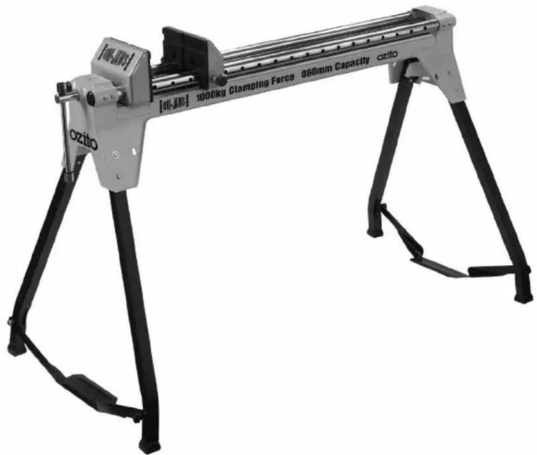
SPECIFICATIONS - MODEL NO. UJC-860
Jaw Size: 180mm x 75mm
Clamping Capacity: 860mm
Clamping Force: 1000kg
Rail Diameter: 32mm
Rail Detents: 12 x 75mm
KNOW YOUR PRODUCT
![[UH-JWS] 1000kg Clamping Force 860mm Capacity ozito ozito 1 2 3 7 8 9 10 11 12 13 14 15 16 17 18](/content/2026/05/929702/images/da59a6ca6a358885608c9d1c75e3459f1331ed6b5a50416c592cb1e866c450c9.jpg)
- Front vice jaw
- Rear vice jaw
- Urethane jaw facings (x2)
- Hex screws (x4)
- Front vice jaw clamping handle
- Rear vice jaw locking pins (x2)
- Vice rails
- Vice rail detents (x12)
- Front leg locking pin (x2)
-
Rear leg locking pin (x2)
-
Front legs (x2)
- Rear legs (x2)
- Front leg support brace
- Front support brace locking knob
- Rear leg support brace
- Rear support brace locking knob
- Uni-Jaws bed
- Log jaws (x2)
- 6mm Hex Key
TABLE OF CONTENTS
SPECIFICATIONS......Page 1
KNOW YOUR PRODUCT......Page 1
INTRODUCTION...... Page 3
SAFETY INSTRUCTIONS...... Page 3
SETTING UP...... Page 4
OPERATION...... Page 6
MAINTENANCE Page 10
CONTENTS Page 10
WARRANTY......Page 11
INTRODUCTION
The Uni-Jaws are the ultimate portable work vice for the workshop. With a powerful clamping force of up to 1000kg and large vice jaws the Uni-Jaws will hold just about anything including timber, metal and even logs when fitted with the log jaws.
The Uni-Jaws feature twin chrome rails for greater durability and easy sliding of the rear jaws, with 12 indents the quick-release rear jaws can be quickly adjusted to suit both small and large workpieces.
As opposed to a traditional vice positioned on a workbench the Uni-Jaws give you 360° access to your workpiece for ultimate flexibility and ease of use.
The steel construction increases durability and extends the life of the jaws whilst the folding legs provide stability on most surfaces and can be easily folded-up to allow fo easy storage and transportation.
This product is intended for DIY use only.
SAFETY INSTRUCTIONS
WARNING! Read and understand all instructions. Failure to follow all instructions listed below may result in personal injury.
- Make sure all moving parts are free from interference.
- Keep hands clear of all moving parts.
- Ensure Uni-Jaws is set-up on firm ground in a stable manner.
- Use Uni-Jaws in a dry place protected from rain.
- Keep work area well-lit.
- Never stand or sit on the Uni-Jaws.
- Be aware of overbalancing. When a large piece is cut from one end of a job, the remaining piece may be heavy enough to over-balance the Uni-Jaws. Always ensure the workpiece is well supported.
SAFETY INSTRUCTIONS (cont.)
- When transporting Uni-Jaws in a vehicle always tie it down to prevent movement and possible damage.
- Check to make sure that all fixing screws and knobs are tight and all legs are locked into position before operating the Uni-Jaws.
- The tool must be used only for its prescribed purpose. Any use other than those mentioned in these instructions will be considered a case of misuse. The manufacturer shall not be liable for any damage or injury resulting from such cases of misuse.
- The manufacturer shall not be liable for any changes made to the tool nor for any damage resulting from such changes.
SETTING UP
- The Uni-Jaws comes fully assembled. To operate the Uni-Jaws follow the simple set-up instructions.
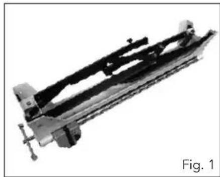
- Remove the Uni-Jaws from the carton and carefully place it upside down on a flat surface (Fig. 1).
- Start by unfolding the front legs (11). Press the front leg locking pin (9) (Fig. 2).
natural_image
Mechanical assembly component labeled Fig. 1, showing a cylindrical assembly with mounting flanges and internal components (no text or symbols on the component itself)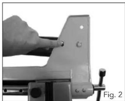
natural_image
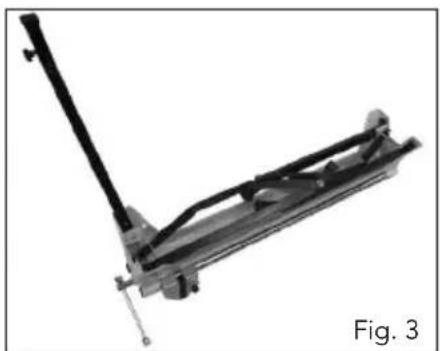
Close-up of a hand using a tool to adjust or install a metal frame (no text or symbols visible)- Unfold the front leg to the fully upright position (Fig. 3) and ensure that the locking pin clicks into the opposite pin hole (A) (Fig. 4).
natural_image
Mechanical assembly component labeled Fig. 3, showing a lever and bracket (no text or symbols on the device itself)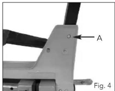
SETTING UP (cont.)
-
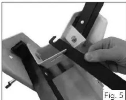
To raise the opposite front leg first remove the front leg support brace (13) from the holding bracket (Fig. 5).
-
Fully raise the opposite front leg (Fig. 6) ensuring the locking pin clicks into the opposite pin hole.
-
Swing the support brace (13) to the opposite front leg and place it into position between the front support brace locking knob (14) and front leg.
-
Ensure the brace is positioned between the washer and front leg.
-
Tighten the support brace locking knob (14) to secure the support brace into position (Fig. 7).
-
Repeat steps 3 to 9 for the rear legs (12) until all 4 legs are in the upright position and secured with the support braces (Fig. 8).
-
Prior to turning over the Uni-Jaws ensure that all 4 locking pins (9 & 10) have clicked into the correct holes and the support braces (13 & 15) are locked in with the support brace locking knobs (14 & 16).
-
Carefully turn over the Uni-Jaws and place it into the upright position (Fig. 9).
natural_image
Close-up of a hand holding a black rectangular object with a small white object, next to a mechanical component (no visible text or symbols)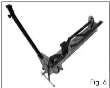
natural_image
Mechanical assembly component labeled Fig. 6, showing a V-shaped lever mechanism (no text or symbols on the device itself)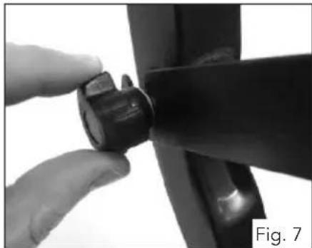
natural_image
Close-up of a hand adjusting a black mechanical component, labeled 'Fig. 7' (no text or symbols on the object itself)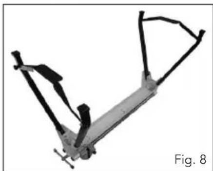
natural_image
Mechanical linkage component labeled Fig. 8, showing articulated arms and joints (no text or symbols on the structure itself)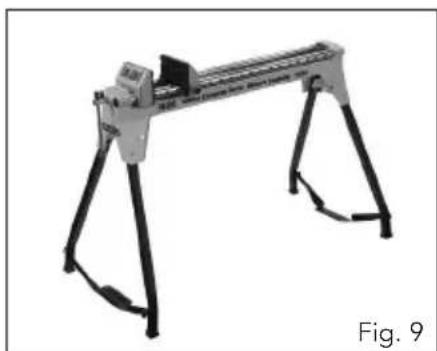
natural_image
Mechanical device with articulated legs and a central lever, labeled Fig. 9 (no text or symbols on the device itself)OPERATION
Adjusting the Front Vice Jaw
- Rotating the front vice jaw clamping handle (5) will move the front vice jaw (1) backwards and forwards (Fig. 10).
- Rotating in a clockwise direction moves the front vice jaw forward towards the rear jaw, rotating in an anti-clockwise direction moves the front vice jaw backwards towards the front of the Uni-Jaws.
Adjusting the Rear Vice Jaw
- The rear vice jaw is adjustable to 12 detent positions (8) located at 75mm intervals.
- To adjust the rear vice jaw pull back on the 2 rear vice jaw locking pins (6) (Fig. 11) and move the rear vice jaw backwards and forwards along the vice rails (7) to the desired detent position (8).
- Letting go of the rear vice jaw locking pins (6) will allow the rear vice jaw to stop at the next available vice rail detent (8).
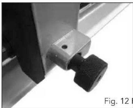
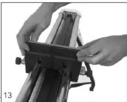
- By pulling back on the 2 rear vice jaw locking pins (6) and rotating 45^ (Fig. 12) the rear vice jaw can be freely moved backwards and forwards along the vice rails (7) without locking into position (Fig. 13).
natural_image
Close-up of a mechanical component with a black and gray piece, labeled 'Fig. 12' (no readable text or symbols on the object itself)Fig. 12 Fig. 13
natural_image
Close-up of hands installing or adjusting a mechanical component on a rail vehicle (no visible text or symbols)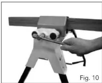
natural_image
Hand operating a mechanical device with a tool, labeled 'Fig. 10' (no other text or symbols visible)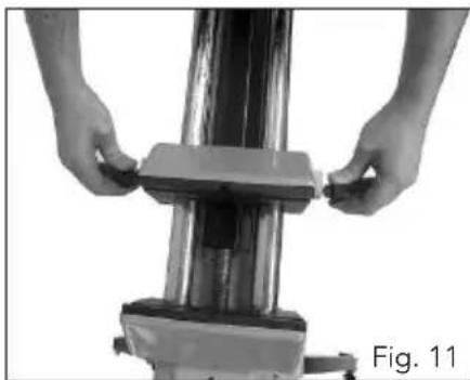
natural_image
Close-up of hands adjusting a mechanical component with a base plate (no visible text or symbols)- When the rear jaw needs to be locked into position simply rotate the rear vice jaw locking pins 45^ one more time, they will now click into the next available detent (8) when moved backwards or forwards on the vice rails (7).
OPERATION (cont.)
Clamping Material
-
Ensure the front vice jaw (1) is located towards the front of the Uni-Jaws.
-
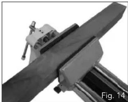
Place the workpiece onto the vice rails in between the front vice jaw (1) and rear vice jaw (2) (Fig. 14).
-
Position the rear vice jaw as close as possible to the front vice jaw and ensure it is locked into one of the 12 detents on the vice rails.
-
Rotate the clamping handle (5) in a clockwise direction to move the front vice jaw towards the rear vice jaw and clamp the workpiece (Fig. 15).
-
Rotate the clamping handle until the vice jaws are securely clamping the workpiece.
natural_image
Close-up of a mechanical clamp or bracket assembly with a metallic rod and metal frame (no visible text or symbols)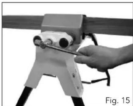
natural_image
Hand operating a mechanical device with a tool, labeled 'Fig. 15' (no text or symbols on the device itself)Fitting the Log Jaws
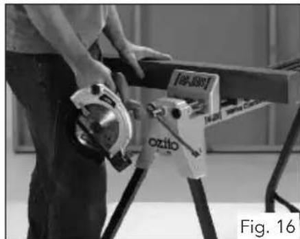
- The Uni-Jaws comes fitted with Urethane jaw facings (3) which can be used for both wood and metal workpieces (Fig. 16 & 17).
natural_image
Person operating a metal tool with a branded box labeled 'ozito' (no readable text or symbols beyond label)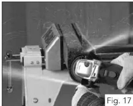
natural_image
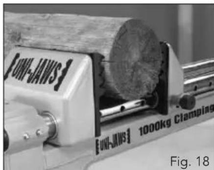
Close-up of hands using a tool to work on a mechanical component, no visible text or symbols- When clamping round logs the Uni-Jaws must be fitted with the log jaws (18) (Fig. 18).
natural_image
Close-up of a UNI-JANS industrial machine with a wooden log and clamping device (no visible text or symbols on the machine itself)OPERATION (cont.)
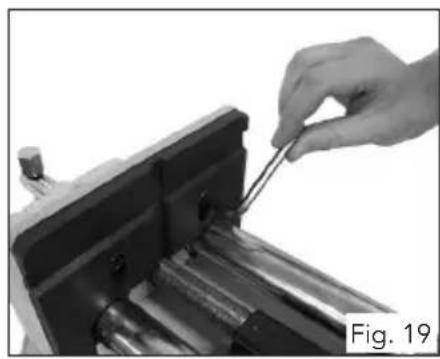
- To replace the jaws first loosen the 2 hex screws (4) on the front jaw by rotating in an anti-clockwise direction using the 6mm hex key (19) (Fig. 19).
- The hex screws do not need to be completely removed, simply loosen until the jaw facing can be raised.
- Slightly raise the jaw facing (3) and remove from the front vice jaw (Fig. 20).
-
Repeat steps 3 to 5 for the rear vice jaw.
-
Attach the log jaw facing (18) onto the front vice jaw ensuring the 2 hex screws are protruding through the 2 slots in the log jaw (Fig. 21).
-
Tighten the 2 hex screws by rotating in a clockwise direction using the 6mm hex key (19) (Fig. 22).
- Tighten both hex screws until the log jaw is secure on the vice jaw.
-
Repeat steps 7 to 9 for the rear vice jaw.
-
The Uni-Jaws can now be used to clamp logs, this is especially useful in chainsaw applications (Fig. 23)
natural_image
Close-up of a hand using a tool to adjust or install a mechanical component (no visible text or symbols)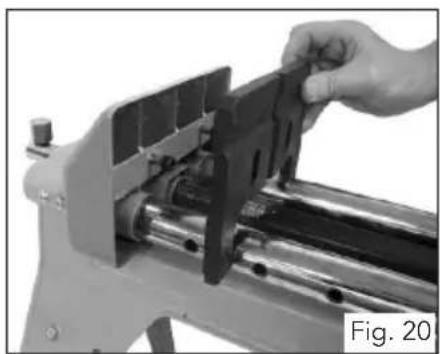
natural_image
Close-up of a hand using a mechanical tool to adjust or install a component, labeled 'Fig. 20' (no other text or symbols visible)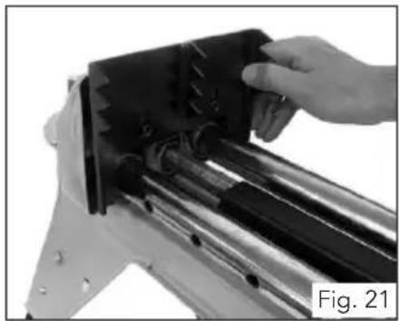
natural_image
Close-up of a hand holding a black mechanical component, possibly a device or tool, with no visible text or symbols.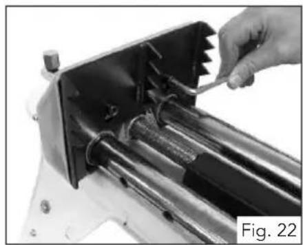
natural_image
Close-up of a hand using a tool to adjust or install a mechanical component, labeled 'Fig. 22' (no text on the object itself)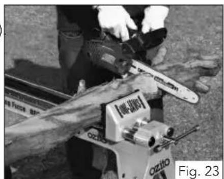
natural_image
Person using a chain-linking machine on a wooden log, no visible text or symbolsOPERATION (cont.)
Storage and Transport
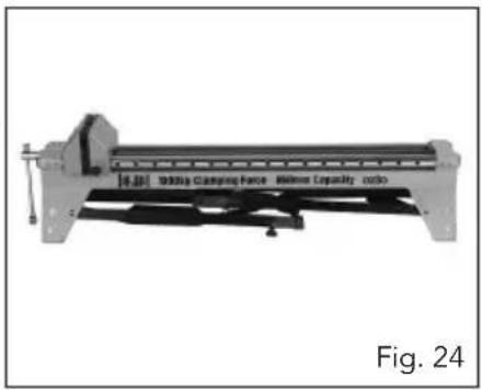
- The Uni-Jaws can be easily folded for convenient storage and transportation (Fig. 24).
- Simply follow the "Setting Up" instructions in reverse to fold-up the Uni-Jaws.
Note: When transporting Un-Jaws in a vehicle always tie it down to prevent movement and possible damage.
natural_image
Mechanical device labeled 'Molding Clamping Force - Silvers Capacity ratio' with no visible text or symbols on the device itself.Mitre Saw Mounts (Optional Accessory)
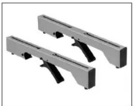
Note: The mitre saw mounts (set of 2) are an optional accessory and not supplied with the Uni-Jaws.
- Mitre saw mounts help extend the capability of the Uni-Jaws (Fig. 25).
- Simply attach the mitre saw mounts to the Uni-Jaws vice rails and turn it into a handy mitre saw stand (Fig. 26).
natural_image
Two metallic mechanical components with black handles, shown in isometric view (no text or symbols)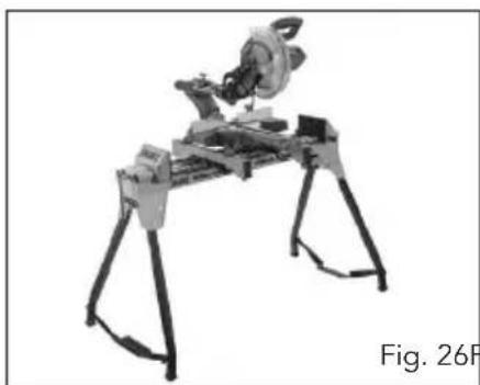
natural_image
Mechanical device with bipod and articulated legs, labeled Fig. 26F (no text or symbols on the device itself)Fig. 26 Fig. 25
Please contact your local Bunnings Special Orders Desk to order the mitre saw mounts
Spare Part Part Number
Mitre Saw Mounts (Pair) SPUJC860-41
MAINTENANCE
- Wipe away dirt and dust from the stand on a regular basis.
Note: Ozito Industries will not be responsible for any damage or injuries caused by the repair of the tool by an unauthorised personor by mishandling of the tool.
CONTENTS
1 x Uni-Jaws UJC-860
2 x Urethane jaws (fiited)
2 x Log Jaws
1 x 6mm Hex Key
1 x Instruction manual
CARING FOR THE ENVIRONMENT

Recycling packaging reduces the need for landfill and raw materials. Reuse of recycled material decreases pollution in the environment. Please recycle packaging where facilities exist. Check with your local council authority for recycling advice.
OZITO INDUSTRIES PTY LTD
AUSTRALIA (Head Office)
1 - 23 Letcon Drive, Bangholme, Victoria, Australia 3175
Telephone: 1800 069 486
Facsimile: +61 3 9238 5588
Website: www.ozito.com.au
Email: enquiries@ozito.com.au
WARRANTY
YOUR WARRANTY FORM SHOULD BE RETAINED BY YOU AT ALL TIMES. IN ORDER TO MAKE A CLAIM UNDER THIS WARRANTY YOU MUST RETURN THE PRODUCT TO YOUR NEAREST BUNNINGS WAREHOUSE WITH YOUR BUNNINGS REGISTER RECEIPT. PRIOR TO RETURNING YOUR PRODUCT FOR WARRANTY PLEASE TELEPHONE OUR CUSTOMER SERVICE HELPLINE:
Australia 1800 069 486 New Zealand 0508 069 486
TO ENSURE A SPEEDY RESPONSE PLEASE HAVE THE MODEL NUMBER AND DATE OF PURCHASE AVAILABLE. A CUSTOMER SERVICE REPRESENTATIVE WILL TAKE YOUR CALL AND ANSWER ANY QUESTIONS YOU MAY HAVE RELATING TO THE WARRANTY POLICY OR PROCEDURE.
The benefits provided under this warranty are in addition to other rights and remedies which are available to you at law.
Our goods come with guarantees that cannot be excluded at law. You are entitled to a replacement or refund for a major failure and for compensation for any other reasonably foreseeable loss or damage. You are also entitled to have the goods repaired or replaced if the goods fail to be of acceptable quality and the failure does not amount to a major failure. Generally you will be responsible for all costs associated with a claim under this warranty, however, where you have suffered any additional direct loss as a result of a defective product you may be able to claim such expenses by contacting our customer service helpline above.
2 YEAR REPLACEMENT WARRANTY
Your product is guaranteed for a period of 24 months from the original date of purchase and is intended for DIY (Do It Yourself) use only. If a product is defective it will be replaced in accordance with the terms of this warranty. Warranty excludes consumable parts, for example: rollers, extension bars, legs and accessories..
WARNING
The following actions will result in the warranty being void.
Professional, Industrial or high frequency use.
- If the tool shows signs of damage or defects caused by or resulting from abuse, accidents or alterations.
Failure to perform maintenance as set out within the instruction manual.
If the tool is disassembled or tampered with in any way.
OZITO
Australia/New Zealand (Head Office)
1-23 Letcon Drive, Bangholme, Victoria, Australia 3175
- SPECIFICATIONS - MODEL NO. UJC-860
- KNOW YOUR PRODUCT
- TABLE OF CONTENTS
- INTRODUCTION
- SAFETY INSTRUCTIONS
- WARNING! Read and understand all instructions. Failure to follow all instructions listed below may result in personal injury.
- SAFETY INSTRUCTIONS (cont.)
- SETTING UP
- SETTING UP (cont.)
- OPERATION
- Adjusting the Front Vice Jaw
- Adjusting the Rear Vice Jaw
- OPERATION (cont.)
- Clamping Material
- Fitting the Log Jaws
- Storage and Transport
- Mitre Saw Mounts (Optional Accessory)
- Spare Part Part Number
- MAINTENANCE
- CONTENTS
- CARING FOR THE ENVIRONMENT
- OZITO INDUSTRIES PTY LTD
- AUSTRALIA (Head Office)
- WARRANTY
- YEAR REPLACEMENT WARRANTY
- WARNING
- OZITO
Brand : Ozito
Model : UJC-860
Category : Uncategorized