
BP260EG - Cooker Bellini - Free user manual and instructions
Find the device manual for free BP260EG Bellini in PDF.


| Product Type | Freestanding Gas Cooker |
| Brand | Bellini |
| Model | BP260EG |
| Energy Source (Hob) | Natural Gas or Universal LPG |
| Energy Source (Oven) | Electric (220-240V, 50Hz) |
| Number of Burners | 4 (Auxiliary, Semi-Rapid, Semi-Rapid, Rapid) |
| Burner Power (Natural Gas) | Aux: 4.0 MJ/h, Semi-Rapid: 6.0 MJ/h, Rapid: 10.0 MJ/h |
| Burner Power (Universal LPG) | Aux: 4.0 MJ/h, Semi-Rapid: 6.4 MJ/h, Rapid: 11.0 MJ/h |
| Oven Capacity | 56 litres |
| Oven Functions | Conventional (top/bottom), Fan, Grill, Fan Grill, Defrost, Light, etc. |
| Oven Temperature Range | 50°C – 250°C |
| Ignition | Electronic spark ignition (requires mains power) |
| Safety Features | Flame safeguard thermocouple, child safety supervision |
| Cleaning (Hob) | Stainless steel – warm soapy water, non-abrasive |
| Cleaning (Oven) | Enamel interior – damp cloth, mild detergent |
| Warranty | 2 years (manufacturing defects) |
| Weight (approx.) | 38 kg |
| Installation Requirements | Professional installation; clearances: 600mm to overhead cupboards, 200mm to sides/rear |
| Gas Connection | 1/2" BSP male thread; regulator supplied |
| Electrical Connection | 10A GPO; cord supplied |
Frequently Asked Questions - BP260EG Bellini
User questions about BP260EG Bellini
0 question about this device. Answer the ones you know or ask your own.
Ask a new question about this device
Download the instructions for your Cooker in PDF format for free! Find your manual BP260EG - Bellini and take your electronic device back in hand. On this page are published all the documents necessary for the use of your device. BP260EG by Bellini.
USER MANUAL BP260EG Bellini
natural_image
Top-down architectural diagram of a four-pit restaurant with circular windows and grid lines (no text or symbols)
natural_image
Pure geometric shape resembling a C or U on black background (no text or symbols)
natural_image
Abstract geometric shape resembling a stylized letter or symbol (no text or symbols present)
natural_image
Technical line drawing of a three-panel gas stove with circular vented dividers (no text or symbols)For warranty service call 1300 373 199(Australia) or 0508 123108(New Zealand) to connect you to the nearest authorised service centre
CGH6401
CGH6401-F
CGH9501
CGH9501-F
BG604X
BG604X-F
BG905X
BG905X-F
- INTRODUCTION AND SAFETY WARNINGS 1
- OPERATING INSTRUCTIONS 2
- CLEANING INSTRUCTIONS 3
- TROUBLESHOOTING 4
- INSTALLATION 5
- SEWARRANGT and PARTS 10
- WARRANTY 10
CGH9501
natural_image
Technical line drawing of a gas stove or gas stove frame with circular components and mounting brackets (no text or symbols)1. INTRODUCTION AND SAFETY WARNINGS
Congratulations on your investment in Bellini, quality stainless steel gas hotplates.
Please carefully read the following installation and operating instructions to ensure you get the safest operation from this appliance.
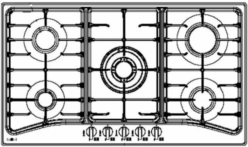
These instructions apply only to the models CGH9501 and BG905X - 5 burner models and the CGH6401 and BG604X - 4 burner models, for use with Natural Gas or Universal LPG.
NOTE: Refer to gas type label and data plate label to ensure appliance is setup for the correct gas type. If in doubt, refer to gas supplier.
WARNINGS:
- Do not use or store flammable materials in the appliance storage drawer or near this appliance.
- Do not spray aerosols in the vicinity of this appliance while it is in operation.
- Do not modify this appliance.
- For Universal LPG appliance:- Where this appliance is installed in marine craft or caravans, it shall not be used as a space heater.
○ Disconnect electricity supply to the appliance before any servicing work is conducted.
This appliance is not intended for use by persons (including children) with reduced physical, sensory or mental capabilities, or lack of experience and knowledge, unless they have been given supervision or instruction concerning use of the appliance by a person responsible for their safety.
Children should be supervised to ensure that they do not play with the appliance. - The appliance electrical supply must allow for disconnection after the installation of the appliance.
- Cord type Y – If the supply cord is damaged, it must be replaced by the manufacturer, its service agent or similarly qualified persons in order to avoid a hazard.
For future reference please store these instructions in a safe place.
2. OPERATING INSTRUCTIONS
LIGHTING THE BURNER
The hotplates are fitted with mains powered electronic spark ignitors, so must be connected to mains power supply (i.e. nominal 230 V ac) to operate. If power is not available, the hotplate will still work but the burners will have to be lit with a match or similar.
Depressing the gas control knob of any burner will activate the spark ignition for all burners. To light the burner, turn the gas control knob to the High Flame setting of the burner to be lit, while at the same time depressing the gas control knob to activate the spark ignition.
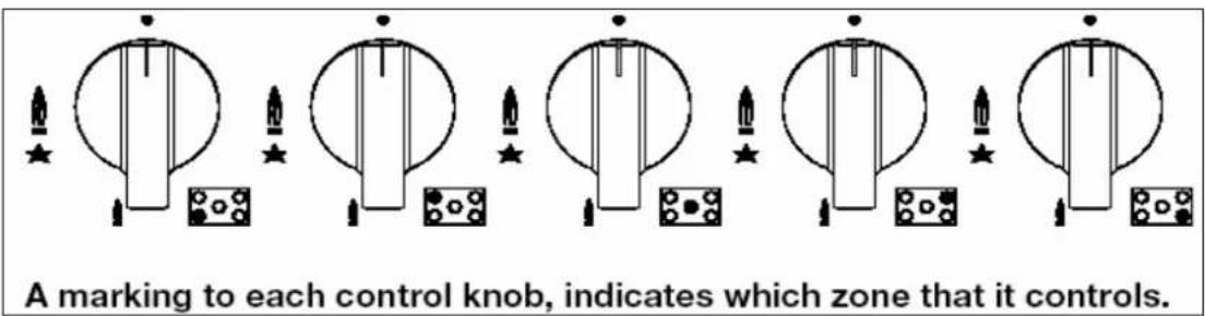
Once the burner is alight continue to depress the gas control knob for 5 – 10 seconds to allow the flame safeguard to activate. If when you release the gas control knob, the burner flame goes out the flame safeguard has not heated up enough so repeat the ignition procedure after waiting 1 minute for gas to disperse. If problems with burner lighting persist, refer to the TROUBLESHOOTING section of these instructions.
If power is not available, light a match or similar, then turn the gas control knob for the burner to be lit, to the High Flame setting. Once again if problems with burner lighting persist, refer to the TROUBLESHOOTING section of these instructions.
When burner lights, adjust desired flame height. On finishing, turn control knob to off position marked with a black DOT.
BURNER AND UTENSIL CHOICE
Depending on the hotplate model, the burner choices are:
Model CGH6401: Auxiliary (small), Semi-Rapid (medium), and Rapid (large) burners.
Models CGH9501 and BG905X: Auxiliary (small), Semi-Rapid (medium), Rapid (large), and Triple ring (wok) burners.
Model BG604X: Auxiliary (small), Semi-Rapid (medium), and Triple ring (wok) burners.
The maximum utensil (pan) diameters in millimetres (mm) for each burner are:
-
For Natural Gas hotplates
-
Auxiliary (small) and Semi-Rapid (medium) = 195 mm
• Rapid (large) = 230 mm
• Triple ring (wok) = 270 mm -
For Universal LPG hotplates
• Auxiliary (small), Semi-Rapid (medium) and Rapid (large) = 195 mm
• Triple ring (wok) = 230 mm
The minimum utensil (pan) diameters in millimetres (mm) for each burner are:
• Auxiliary (small) = 80 mm
• and Semi-Rapid (medium) = 140 mm
• Rapid (large) and Triple ring (wok) = 195 mm
For best efficiency and to ensure utensil handle does not overheat, place the utensil centrally on the burner and adjust the flame height so all the flame remains under the utensil.
3. CLEANING INSTRUCTIONS
GENERAL
Cleaning and maintenance should be carried out with the appliance cold especially when cleaning the enameled parts.
Avoid leaving alkaline or acid substances(lemon juice, vinegar etc.) on the surfaces.
STAINLESS STEEL
The stainless steel hob of the hotplate must be cleaned regularly (e.g. weekly) to ensure long life expectancy of the hotplate.
Ensure hotplate has cooled. Wash down with warm soapy water and rinse with clean water.
Dry with a clean soft cloth. A specialized stainless steel cleaning fluid may be used.
NOTE: Ensure that wiping is done along with the grain of the stainless steel to prevent any unsightly crisscross scratching patterns from appearing.
TRIVETS (UTENSIL SUPPORTS)
Enameled parts must only be washed with a sponge and soapy water or with non-abrasive products. Rinse with clean water. Dry with a clean soft cloth.
BURNERS
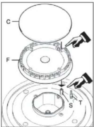
Remove trivets from hob. Ensure burners are cool. Remove the burners enameled cap (C) and aluminium burner crown (F).
Wash down with warm soapy water and rinse with clean water. Dry with a clean soft cloth.
Replace burners and ensure they are correctly re-positioned over the ignitor (S) and thermocouple (T). The ignitor (S) must be clean for trouble free sparking. Test burner ignition and burner flame for correct operation.
The Triple Ring (Wok) burner (diagrams below) does not fit over the ignitor or thermocouple but must be placed on its supports. If burner is placed correctly it will not rotate on its supports.
Refer to diagrams below.

natural_image
Mechanical assembly diagram showing a gear and rotor assembly with a directional arrow (no text or labels)
4. TROUBLESHOOTING
Servicing of the hotplates must only be done by an authorised service representative (see back of this booklet) and the hotplate must not be modified. Power must be disconnected before any servicing or maintenance is conducted.
Abnormal conditions include : Excessively yellow or sooting flame type.
: Flame lifting off the burner ports.
: Flame lighting back into the burner (normally associated with a popping sound).
: Objectionable odour of the flames combustion products.
Should a faulty condition develop in the hotplate that is not described above, refer to the following table first for possible causes and remedies prior to contacting an authorised service representative. Servicing beyond the remedies listed shall only be undertaken by an authorised service representative.
TROUBLESHOOTING TABLE
| FAULT | POSSIBLE | CAUSE |
| No spark when gas control knob depressed. Loose sparker cable. Call authorised representative. Burner not aligned properly. Remove and re-fit burner. | No | Check plugged in and switched on. Check mains circuit breaker. |
| pressed representative. | ||
| Burner not lighting when spark ignition working. Gas supply off. Burner not aligned properly. Remove and re-fit burner. | ||
| Remove, clean and replace burner. | ||
| Burner ports blocked. | ||
| Burner goes out when control knob released. | Flame safeguard not activated. | Re-light, allow more time for flame safeguard to activate. |
| Flame safeguard faulty connection or broken. Call authorised representative. | ||
| Uneven flame pattern or slight flame lifting. Burner ports blocked. | Remove, clean and replace burner. | |
| At minimum flame setting the flame is too high. | Turndown control setting incorrect. Call authorised representative. | |
| Small flame on High setting. Regulator faulty. Call authorised representative. | ||
| Gas supply pressure low. | Call authorised representative. | |
| Incorrect injector fitted. | Call authorised representative. | |
| Blocked injector or gas supply tube. | Call authorised representative. | |
| Incorrect utensil size. | Refer to operating instructions - utensil choice. | |
| Flame too high on High setting. | Regulator faulty. Call authorised representative. | |
| Incorrect injector fitted. | Call authorised representative. | |
| Incorrect utensil size. | Refer to operating instructions - utensil choice. | |
5. INSTALLATION
IMPORTANT NOTE: Refer to the Warnings in Section 1 of these Instructions.
This hotplate must be installed in accordance with:
• AS 5601 - Gas Installations (for Australia)
- NZS 5261 - Code of Practice for the Installation of Gas Burning Appliances and Equipment (for New Zealand)
- Local gas fitting regulations
• AS/NZS 3000 - Electrical Installations (Wiring Rules)
- Building codes
- Any other relevant statutory regulations.
Check the gas type label on the underside of the hotplate, adjacent to the gas connection to ensure it corresponds to the installation gas supply. If in doubt contact the supply authority.
NOTE: Before cutting into any bench tops, ensure the minimum clearances to walls, adjacent surfaces and overhead surfaces required by the relevant gas appliance installation code (see above) will comply. Dimensions are specified in millimetres (mm)
MINIMUM CLEARANCES:
• Overhead cupboards and range hood = 600 mm.
- Side and rear clearance = 200 mm to any burner edge.
• Overhead exhaust/ceiling fan = 750 mm
• Horizontal surfaces adjacent the hob = less than or equal to the hob height.
- Ensure there is sufficient clearance to fit the regulator and/or flexible hose connection with the hotplate in the installed position.
GAS and ELECTRICAL CONNECTION LOCATIONS and OVERALL DIMENSIONS:
Model CGH6401: Bench cutout size, 555 mm wide x 473 mm deep.
Bench top thickness, 30 - 40 mm (3 - 4 cm).

Model CGH9501: Bench cutout size, 830 mm wide x 473 mm deep. Bench top thickness, 30 - 40 mm (3 - 4 cm).
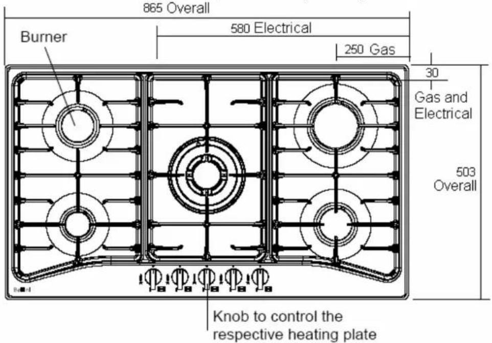
Model BG604X: Bench cutout size, 555 mm wide x 473 mm deep. Bench top thickness, 30 - 40 mm (3 - 4 cm).
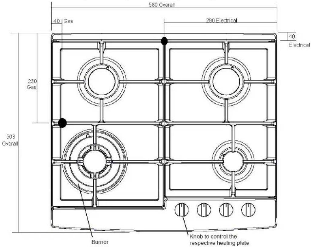
Model BG905X: Bench cutout size, 830 mm wide x 472 mm deep. Bench top thickness, 30 - 40 mm (3 - 4 cm).

Once satisfied that minimum clearances to combustible can be achieved, cut out the bench top to the dimensions specified.
Apply the adhesive sealing tape to the underside lip of the burner box. Shown at G opposite.
Place burner box into cutout hole and fit clamping brackets to clamp the hotplate to the bench.
See two clamping method diagrams below:


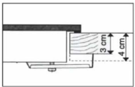
Then a particle board or similar heat baffle must be installed under the hob to prevent accidental touching of the underside surface.
Leave sufficient rear clearance to access gas and electrical connections.
ELECTRICAL CONNECTION:
Install a 10 amp general purpose outlet (GPO) in accordance with relevant electrical standards and/or codes of practice applicable.
The power supply cord (supplied) must not touch against any hot surfaces and must be placed so that its temperature does not exceed 75^ C at any point along its length.
After having installed the hotplate, the GPO must always be in an accessible position.
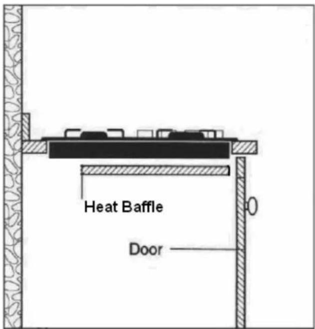
GAS CONNECTION:
Install in accordance with relevant gas standards and/or codes of practice applicable.
Connect the elbow fitting to the appliance gas manifold connection.
For Natural gas: connect the natural gas appliance regulator (pictured opposite) with integral test point using approved gas thread tape or compound to the elbow fitting.
For Universal LPG: connect the brass test point adaptor (pictured opposite) using approved gas thread tape or compound to the elbow fitting.
Ensure the supply connection point, test point and natural gas regulator adjustment screw (for Natural gas installation) are accessible for testing and/or adjustment with the hotplate in the installed position.
Where a flexible hose assembly is used, ensure it is approved to AS/NZS 1869, Class B. Any hose assembly used must be restrained from accidental contact with the flue outlet of an under bench oven.


After connecting to gas, check for leaks using soapy solution, never a naked flame.
Fit the duplicate data plate (supplied in separate bag) on a surface adjacent to the hotplate, for example, the inside of the cupboard door so it is clearly visible for any service technician.
SETTING THE GAS PRESSURE:
Fit a manometer with a 6 mm rubber hose to the test point on the regulator (for natural gas).
For the Model CGH6401, light one Rapid and Auxiliary burner and adjust test point pressure to 1.00 kPa. Turn the two burners off and on again and recheck the pressure is same as set previously or adjust as required.
For the Models CGH9501, BG604X and BG905X, light the Triple Ring and Auxiliary burner and adjust test point pressure to 1.00 kPa. Turn the two burners off and on again and recheck the pressure is same as set previously or adjust as required.
TEST FOR CORRECT OPERATION:
After installation and test point setting, each burner ignition and operation must be tested individually and with all burners operating.
This testing must be done by the installer before leaving.
NOTE: This adjustment can only be performed by authorised service personnel.
The minimum burner flame is factory adjusted for the gas type stated on the gas type label adjacent to the gas connection and should not require adjustment.
Adjustment may be required if the hotplate has been converted from Natural gas to Universal LPG or vice versa.
GAS CONVERSION INSTRUCTIONS:
The manufacturers servicing instructions detail how authorised personnel may convert the hotplate from Natural gas to Universal LPG or from Universal LPG to Natural gas.
Contact the manufacturer or agent as required.
| Model CGH6401 | NATURAL GAS UNIVERSAL LPG | |||||
| Inj Diam MJ/h Test point kPa | Inj Diam MJ/h Test point kPa | |||||
| Auxiliary | 0.90 | 4.0 | 1.00 | 0.55 | ||
| Semi rapid 1.10 6.0 | 1.00 | 0.70 | 6.4 | 2.75 | ||
| Semi rapid 1.10 6.0 | 1.00 | 0.70 | 6.4 | 2.75 | ||
| Rapid | 1.35 | 10.0 | 1.00 | 0.90 | 11.0 | 2.75 |
| TOTAL NHGC | 26.0 | MJ/h | 27.8 | MJ/h | ||
| Model CGH9501 | NATURAL GAS UNIVERSAL LPG | |||||
| Inj Diam MJ/h Test point kPa | Inj Diam MJ/h Test point kPa | |||||
| Auxiliary | 0.90 | 4.0 | 1.00 | 0.55 | ||
| Semi rapid 1.10 6.0 | 1.00 | 0.70 | 6. 4 | 2.75 | ||
| Semi rapid 1.10 6.0 | 1.00 | 0.70 | 6.4 | 2.75 | ||
| Rapid | 1.35 | 10.0 | 1.00 | 0.90 | 11.0 | 2.75 |
| Triple ring | 1.70 | 14.0 | 1.00 | 0.98 | 12.5 | 2.75 |
| TOTAL NHGC | 40.0 | MJ/h | 40.3 | MJ/h | ||
| Model BG604X | NATURAL GAS UNIVERSAL LPG | |||||
| Inj Diam MJ/h Test point kPa | Inj Diam MJ/h Test point kPa | |||||
| Auxiliary | 0.90 | 4.0 | 1.00 | 0.55 | ||
| Semi rapid 1.10 6.0 | 1.00 | 0.70 | 6.4 | 2.75 | ||
| Semi rapid 1.10 6.0 | 1.00 | 0.70 | 6.4 | 2.75 | ||
| Triple ring | 1.70 | 14.0 | 1.00 | 0.98 | 12.5 | 2.75 |
| TOTAL NHGC | 30.0 | MJ/h | 29.3 | MJ/h | ||
| Model BG905X | NATURAL GAS UNIVERSAL LPG | |||||
| Inj Diam MJ/h Test point kPa | Inj Diam MJ/h Test point kPa | |||||
| Auxiliary | 0.90 | 4.0 | 1.00 | 0.55 | ||
| Semi rapid 1.10 6.0 | 1.00 | 0.70 | 6.4 | |||
| Semi rapid 1.10 6.0 | 1.00 | 0.70 | 6.4 | 2.75 | ||
| Rapid | 1.35 | 10.0 | 1.00 | 0.90 | 11.0 | 2.75 |
| Triple ring | 1.70 | 14.0 | 1.00 | 0.98 | 12.5 | 2.75 |
| TOTAL NHGC | 40.0 | MJ/h | 40.3 | MJ/h | ||
WARRANTY
1.1 In this warranty:
1.1.1 Australian Consumer Law means the law as set out in Schedule 2 of the Competition and Consumer Act 2010;
1.1.2 Company means GSM Sales Pty Ltd ACN 007 682 475 of 101 Port Wakefield Road Cavan SA 5094. Telephone 08 8139 7399. Email admin@gsmsales.com.au
1.1.3 Consumer means a “consumer” as that term is defined in Section 3 of the Australian Consumer Law as the original purchaser of a Bellini product;
1.1.4 Consumer Guarantees means the guarantees under the Australian Consumer Law;
1.1.5 You means the Consumer.
1.2 Nothing in this warranty affects any person's rights under the Australian Consumer Law. The benefits to any Consumer under this warranty are in addition to the rights and remedies available under any Consumer Guarantees.
1.3 Subject to the other clauses of this warranty, the Company warrants to the Consumer that the Bellini product will be free of manufacturing defects and will perform to the Company's specifications.
1.4 The benefit of this warranty extends only to the Consumer as original purchaser of a Bellini product which is installed in a residential property.
1.5 This warranty commences on the date of purchase of the Bellini product by the Consumer and continues for the benefit only of the Consumer until the expiry of two (2) years (Warranty Period).
1.6 If within the Warranty Period a manufacturing defect is discovered in the Bellini product or it fails to perform to the Company's specifications as a result of some defect in materials, components or workmanship (Defect) then the Company will, at its option, repair the Bellini product or supply a replacement Bellini product free of charge. A replacement Bellini product may differ from the original product purchased by the Consumer.
1.7 This warranty will not apply to any Bellini product:
1.7.1 Installed by any person other than a qualified tradesperson; or
1.7.2 Subjected to misuse, neglect, negligence or accidental damage; or
1.7.3 Operated in any way contrary to any operating or maintenance instructions; or
1.7.4 Improperly handled, installed or maintained; or
1.7.5 Altered or modified prior to or after installation; or
1.7.6 Damaged directly or indirectly by power surges, electrical storm damage or connection to incorrect power supply
The Australian Consumer Law requires the inclusion of the following statement
with this warranty:
Our goods come with guaranteed that cannot be excluded under the Australian Consumer Law. You are entitled to a replacement or refund for a major failure and for compensation for any other reasonably foreseeable loss or damage. You are also entitled to have the goods repaired or replaced if the goods fail to be of acceptable quality and the failure does not amount to a major failure.
IN ORDER TO MAKE A CLAIM UNDER THIS WARRANTY THE CONSUMER MUST CALL 1300 373 199 (AUSTRALIA) OR 0508 123 108 (NEW ZEALAND) TO CONNECT TO THE NEAREST AUTHORISED CENTRE
1.8 You must provide proof of your purchase of the Bellini product and the date of purchase in order to obtain the benefit of this warranty.
1.9 If you live outside the service area of the Company or one of its service agents, this warranty does not cover the cost of transport of the Bellini product for service nor the service agent's traveling costs to and from your home.
1.10 If you are required to transport the Bellini product to the Company or its service agent, you must ensure it is safely disconnected by a qualified tradesman and securely packed and insured. The Company does not accept any responsibility for loss or damage of the Bellini product prior to it being received by the Company or its service agent.
1.11 You will be responsible for all costs of returning a Bellini product to the Company and for redelivery of the Bellini product by the Company (whether it is the original or a repaired and/or a replacement Bellini product) and for any other expenses you incur in claiming under this warranty.
1.12 The Company or its service agent will examine any Bellini product and if the Company determines that it is defective through no fault of the Owner and is otherwise undamaged, the Company will repair or replace the Bellini product in accordance with this warranty.
DO NOT SEND IN THIS WARRANTY
Fill out the following details and file with your purchase invoice.
RETAIN & FILE WITH YOUR RECEIPT
Your Purchase Receipt/Invoice is proof of date of purchase. If you are unable to establish the date of purchase, or if the fault is not covered by this warranty, or if the product is found to be in working order, you will be required to bear all service call charges.
GSM Sales Pty Ltd reserves the right to discontinue items, modify designs and change specifications without incurring obligation.
Whilst every effort is made to ensure that descriptions, specifications and other information in this publication is correct, no warranty is given in respect thereof and the company shall not be liable for any errors therein.
Purchased from:
Co. Name:
Address:
Date of Purchase:
Serial number:
NOTE: Consistent with our continuing product development policy, improvements may have been made which render the contents of this packaging slightly different to that shown.
FOR WARRANTY SERVICE CALL 1300 373 199 (AUSTRALIA) OR 0508 123 108 (NEW ZEALAND) TO CONNECT YOU TO THE NEAREST AUTHORISED SERVICE CENTRE

Gerard Sourcing & Manufacturing
GSM Sales Pty Ltd.
The GSM Sales Pty Ltd. Group of Companies has a policy of continual improvement throughout the product range. As such the unit contained within may differ slightly from the unit illustrated on the pack.
MADE IN CHINA for the GSM Sales Pty Ltd. Group of Companies

N1028
60cm Built In Oven

natural_image
Line drawing of a standard black oven with digital display and control buttons (no text or symbols)Installation and User manual
Content
Important Safety instructions---- 2
Product description----4
Installation----7
Start using your oven----9
Maintenance and cleaning---- 14
Warranty 16
For warranty service call 1300 373 199(Australia) or 0508 123108(New Zealand) to connect you to the nearest authorised service centre
BO6602X-1(F)
BO610CX-1(F)
BO610CX-2(F)
BO604B(-F)
BO607B(-F)
Important Safety Instructions
This manual explains the proper installation and use of your oven, please read it carefully before using even if you are familiar with the product. The manual should be kept in a safe place for future reference.
General Warnings
If the supply cord is damaged, the cord must be replaced by the manufacturer, its service agent or similarly qualified persons in order to avoid a hazard.
◆ This product has not been designed for any uses other than those specified in this booklet.
◆ This appliance must not be used as a space heater.
In order to avoid fire, the appliance must be kept clean and vents kept unobstructed.
◆ Do not spray aerosols within the vicinity of the appliance during operation.
◆ Do not store flammable materials in or under the appliance, e.g. aerosols.
Do not line the bottom of the oven with foil or cookware.
◆ Always use gloves when handling hot items inside the oven.
◆ Always turn the grill off immediately after use as fat left behind may catch fire.
Do not leave the appliance unattended when cooking. Oils and fats may catch fire due to overheating or boiling over.
Do not put pans weighing over 15Kgs on the opened door of the oven.
Do not use the appliance in the event of a technical fault. Any faults must be fixed by an appropriately qualified and authorised person.
◆ In the event of any incident caused by a technical fault, disconnect the power and report the fault to the service centre to be repaired.
◆ The rules and provisions contained in this instruction manual should be strictly observed.
Do not allow anybody who is not familiar with the contents of this instruction manual to operate the appliance.
Child Safety
This appliance is not intended for use by persons (including children) with reduced physical, sensory or mental capabilities, or lack of experience and knowledge, unless they've been given supervision or instruction concerning use of the appliance by a person responsible for their safety.
◆ Children should be supervised to ensure that they do not play with the appliance.
During use this appliance becomes hot. Care should be taken to avoid touching hot surfaces, e.g. oven door, heating elements.
◆ Accessible parts will also become hot when in use. To avoid burns and scalds children should be kept away.
Installation, Cleaning & Servicing
The appliance must be installed only by an authorised person in compliance with the instructions provided. Incorrect installation may cause harm to persons, animals or may damage property.
◆ Before using the appliance, ensure that all packing materials are removed from the appliance.
◆ In order to avoid any potential hazard, the enclosed installation instructions must be followed.
◆ Ensure that all specified vents, openings and air spaces are not blocked.
◆ The panels adjacent to the oven must be made of heat-resistant material.
◆ Cabinet with a veneer exterior must be assembled with glues which can withstand temperature of up to 120°C.
◆ THIS APPLIANCE MUST BE EARTHED.
To reduce the risk of fire, do not place or install this unit in areas where the ventilation or circulation ducts may become blocked. Make sure there are at least 10mm of space between the back of your oven and the wall. Keep some distance on each side of your oven that you can use that distance flowing installing instructions.
The unit's power cord must be connected to a properly grounded and protected, 220-240V electrical outlet. Always use ground fault protection where required by the electrical code.
When transporting or storing the unit, keep it in a dry location, free from dust, excessive vibration or other factors, which may damage the unit.
Do not operate oven with a damaged cord, plug or if the oven has malfunctioned or has been dropped or damaged in any manner. Return oven to authorised service facility for repair.
Only authorised personnel should carry out servicing. (Certificate of Compliance to be retained)
◆ Always ensure the appliance is switched off before cleaning or replacing parts.
◆ Do not use steam cleaners, as this may cause moisture build-up.
◆ Always clean the appliance immediately after any food spills.
◆ To maintain safe operation, it is recommended that the product be inspected every five years by an authorised service person.
Oven
During use the appliance becomes hot. Care should be taken to avoid touching the hot surfaces inside the oven.
◆ Switch the appliance off before removing the oven light glass for globe replacement.
◆ To avoid an accident, ensure that oven shelves and fittings are always inserted into the appliance in accordance with the instructions.
◆ Do not use the door as a shelf.
◆ Do not push down when the oven door is open.
Grill
Do not cover the grill insert with foil, as fat built up may catch on fire.
◆ Always keep the grill dish clean as any build up may catch on fire.
◆ Do not leave the grill on unattended.
◆ To avoid fire, ensure that grill trays and fittings are always inserted into the appliance in accordance with the instructions.
◆ Do not place thick portions of food under the grill. Foods may curl, catch and ignite.
◆ Accessible parts may become hot when grill is in use. Children should be kept away.
Environmental Hints
◆ Use the oven efficiently, by cooking many trays of food at the same time.
◆ Cook 2 trays of scones, small cakes or sausage rolls at the same time.
- Select the correct shelf location for food being cooked.
◆ Do not open the oven door more than necessary.
◆ After the oven is turned off it retains heat for some time.

This product must not be disposed together with domestic waste. This product has to be disposed at an authorised place for recycling of electrical and electronic appliances.
By collecting and recycling waste, you help save natural resources, and make sure the product is disposed in an environmental friendly and healthy way.
Product Description

A. Function Selection Knob
B. Oven Door Handle
C. Power Indicator Light
D. Temperature Control Knob
E. Heating Indicator Light
F. Glass Do or
Model BO6602X-1, BO6602X-1F

A. Function Selection Knob
B. Minute Timer Knob
C. Oven Door Handle
D. Temperature Control Knob
E. Heating Indicator Light
F. Glass Do or
Model BO610CX-1, BO610CX-1F
Model BO610CX-2, BO610CX-2F

A. Function Selection Knob
B. Temperature Control Knob
C. Oven Door Handle
D. Electronic Control Panel
E. Glass Door
BO610CX-2, BO610CX-2F Time Control Panel

G. Function Display
I. Increase Timer Value
OK button: to confirm setting
H. Control Buttons
J. Decrease Timer Value

L. Timer Override Light*
M. Cooking Duration Function Indicator Light
N. Cooking Delay Start Function Indicator Light
O. Heating Indicator Light
* When this light is ON, all timer functions are overridden and your oven will run in manual mode. Depress "OK" button for 3 seconds to enter into the manual mode.
| Accessory Name Picture Quantity | ||
| Baking tray |  | 1 |
| Grill rack |  | For BO6602X-1(F), BO604B(-F),BO607B(-F) QTY=1;For BO610CX-1(F), BO610CX-2(F)QTY=2 |
| Grill insert |  | 1(BO604B(-F) and BO607B(-F) not provided) |
| Screws(ST4x35) 4 |  | |
Technical Specifications
| model | product dimensions (h x w x d) mm net weight | usable capacity | electrical connection | max. power rating | |
| BO604B(-F) | 595 x 595 x 575 | Approx. 38Kg | 56 litres | 220-240V/50Hz | 2.2kW |
| BO607B(-F) | 595 x 595 x 575 | Approx. 38Kg | 56 litres | 220-240V/50Hz | 2.9kW |
| BO6602X-1(F) | 595 x 595 x 575 | Approx. 38Kg | 56 litres | 220-240V/50Hz | 2.9kW |
| BO610CX-1(F) | 595 x 595 x 575 | Approx. 38Kg | 56 litres | 220-240V/50Hz | 2.2kW |
| BO610CX-2(F) | 595 x 595 x 575 | Approx. 38Kg | 56 litres | 220-240V/50Hz | 2.2kW |
Installation
WARNING!
Please follow the points below when installing the appliance
Use An Authorized Person
As stated in the local municipal building codes and other relevant statutory regulations:
◆ Wiring connections must be in accordance with AS/NZS 3000 Wiring Rules and any particular conditions of the local authority.
◆ Refer to data plate for rating information. The data plate is positioned at the side of cavity.
◆ A functional switch should be provided near the appliance in an accessible position. Refer to AS/NZS 3000 clause 4.7.1.
◆ Wiring should be protected against mechanical failure. Refer to AS/NZS 3000 clause 1.5.
A means of disconnection with a contact separation of at least 3mm must be supplied in the fixed wiring.
◆ Disconnect the power plug of the appliance from the power point when conducting maintenance or repairs to the unit
This Appliance Must Be Properly Earthed
◆ Do not lift the appliance by the door handles.
◆ Prepare the cupboard opening to match your appliance measurements. (See diagrams).
◆ Slide appliance in to cabinet cavity, ensuring supply cable is not obstructed (kinked, jammed or twisted).
◆ To prevent tipping or dislodging of the appliance, secure appliance to the cabinet with 4 screws (provided), through the dedicated holes in the appliance frame.
Where the appliance is built into a cabinet, the cabinet material must be capable of withstanding 70°C. Installation into low temperature tolerant cabinetry (E.g. vinyl coated) may result in deterioration of the low temperature coating by discoloring or bubbling.
The cabinet panels to the oven must be heat resistant. With veneered wood units, glues must be resistant to a temperature of 100^ C.
◆ If the appliance is to be installed adjacent to vinyl wrapped surfaces, use an installation kit
available from the vinyl-wrap supplier.
◆ GSM cannot accept responsibility for damage caused by installation into low temperature tolerant cabinets.
◆ After installation, test and ensure the appliance operates correctly before handing it over to the customer.
CAUTION!
Where the appliance is connected via power supply cable to a power point, the installed power point must remain accessible after appliance installation
A dedicated power circuit is recommended for the unit but not required. Additional electrical appliances on the same circuit may exceed the current (amperage) rating for that circuit. If after the installation of your unit the circuit breaker trips or the fuse fails on a repeated basis, then a dedicated circuit will likely be required.
WARNING!
To avoid any potential hazard, you must follow our instructions when you install your appliance. Failure to install the appliance correctly could invalidate any warranty or liability claims and lead to prosecution.
Install the shelf

natural_image
Line drawing of an oven with a close-up inset showing internal structure (no text or symbols)- Pay attention to high temperature, you may need to wear gloves if it is hot inside.
- Always slide shelves into the layer with stopper.
Cut-out dimensions

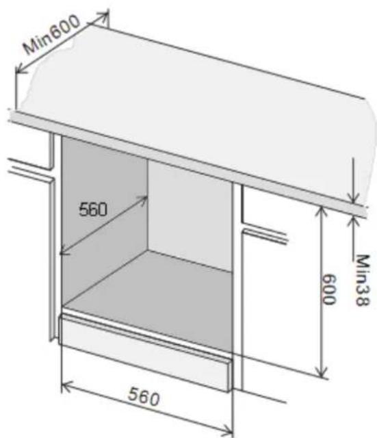

CAUTION!
Your appliance must be mounted on a flat surface for the full width and depth of the product.
Connect power supply cord
◆ Open terminal board cover at rear panel of appliance.

◆ Connect wires as below:

flowchart
graph TD
    A["1"] --> B["2"]
    B --> C["3"]
    D["+"] --> E["5"]
    F["PE"] --> G["N"]
    H["L1"] --> I["1"]
    I --> J["2"]
    J --> K["3"]
    L["+"] --> M["5"]
    M --> N["4"]
◆ Close the terminal board cover.
Start Using Your Over
Preparing Your Oven
- Please remove all stickers, leaflets and boxes from the door and from the floor of the oven before operation.
- Please wipe out the oven interior prior to operation with warm soapy water and polish dry with a soft clean cloth.
Do not close the oven door until the oven is completely dry.
- To remove the new cooker smell, heat up the oven when it is empty and closed. An hour of top/bottom
heating ☐ at 240^ C is ideal for this purpose. Ensure that no packaging remnants have been left in the cooking compartment.
BO610CX-1, BO610CX-1F, BO610CX-2, BO610CX-2F
Turn ON the power to the Appliance, depress "OK" button for 3 seconds, the Timer Override light will be turned on and the oven enters into Manual Mode.
Select the functions ( All Models )
To select the desired function, push the "Function Selection Knob" and the knob will pop up. Turn the knob in any direction to select the desired function.
Model BO604B, BO604B-F (4 functions)

➢ Model BO607B, BO607B-F (7 functions)

➢ Model BO6602X-1, BO6602X-1F (6 functions)

Model BO610CX-1, BO610CX-1F, BO610CX-2, BO610CX-2F(10 functions)

| Function Description | |
| 0 Switch off function | |
Oven Light | By setting the knob to this position the lighting inside the oven is switched on, e.g. use when washing the oven chamber. |
Fan & Combined Grill | When the knob is turned to this position, the oven activates the combined grill and fan function. In practice, this function allows the grilling process to be speeded up and an improvement in the taste of the dish. You should only use the grill with the oven door shut. |
Combined Grill(Grill & Top element) | When the “combined grill” is active, it enables grilling with the grill and with the top heater switched on at the same time. This function allows a higher temperature at the top of the cooking area, which causes more intense browning of the dish and permits larger portions to be grilled. |
Rear Heater With Fan | This cooking mode allows even distribution of the heat inside the oven, making it possible to cook several items of food at the same time. |
Fan, Bottom & Top Elements | Conventional mode with fan. |
Bottom & Top Elements | Allows the oven to be heated conventionally. |
Defrost | To achieve an even and fast defrost of frozen food. This function can be used with any type of frozen food. |
Top Element | Oven is heated using only the top element. |
Bottom Element | Oven is heated using only the bottom element. |
Fan & Top Element | The top element and fan function are activated causing hot air to circulate around the dish. |
Fan & Bottom Element | The bottom element and fan function are activated causing hot air to circulate around the dish. |
Grill Element | Allows dishes to be grilled. |
Fan & Grill Element | This method uses the grill in conjunction with the fan, to help a fast circulation of heat. Suitable where quick browning is required and "sealing" the juices in. |
Select the temperature ( All Models )
To select the desired temperature, push the "Temperature Control Knob" and the knob will pop up. Turn the knob in a clockwise direction to desired temperature (50°C \~ 250°C).
◆ A thermostat controls the temperature in your oven. Heating Indicator Light remains ON when heating the oven. Heating Indicator Light will turn OFF when the oven reaches set temperature.
Once the food is cooked, turn the temperature selector back in an anti-clockwise direction. Do not force it right round in a clockwise direction as this will result in damage to the thermostat.

CAUTION!
◆ The desired cooking function must be selected before the oven will operate.
Work With Minute Timer
Model BO6602X-1, BO6602X-1F
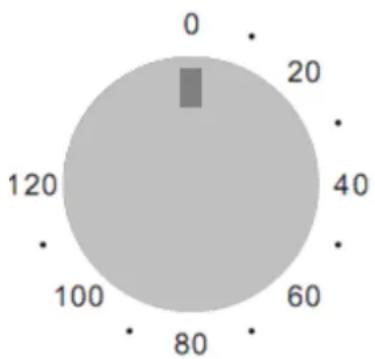
This model has a Minute Timer built inside to give a sound alert when time is up, but oven keep heating. To select this function, push the “Minute Timer Knob” and the knob will pop up. Turn the knob clockwise to the required time.
◆ The timer can be used independently of an oven cooking function for a time period of up to 120 minutes.
The time period that has been set will expire when the control knob reaches zero, a brief audible signal will sound.
radar
| Angle | Value | |---|---| | 0 | 0 | | 90° | 20 | | 180° | 40 | | 370° | 60 | | 560° | 80 | | 750° | 100 | | 940° | 120 |Model BO610CX-1, BO610CX-1F, BO610CX-2, BO610CX-2F
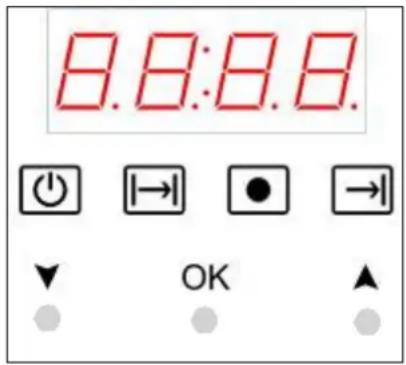
Your oven is equipped with a 3 button timer that has the following features:
◆ O'clock time – you can set current O'clock time
Timer – you can set timer by below three methods to control your oven start/end cooking as you wish. When set program end, beep will sound and the oven stop heating.
◆ Cooking duration – you can set cooking duration. A timer will count down the preset cooking time, beep when the time has elapsed and turn the appliance off.
◆ Cooking end time – instead of setting a cooking duration you can set a cooking finish O'clock time. When the finish time has been reached the timer will beep and turn the appliance off.
- Delayed start cooking time – you can combine the cooking duration and cooking end time to switch oven on and off at a specific time during the day.
O'Clock Time Setting
When the power is connected, the LED display shows 12:00 as default. Press the "OK" key once, "Hour" display will flash, use ▲or▼key to adjust to current O'clock hour then press "OK"; press again, then "Minute" display will flash. use ▲or▼key to adjust to current O'clock minute then press "OK"
Cooking Duration Setting
Before using this function, please make sure "Timer Override" light is off.
➢ Press OK till 📋 and “Hour” display flash together, use ▲ or key to adjust to required cooking hours. Press OK again, “Minute” display flash, use ▲ or key to adjust to required cooking minutes. Press OK again to confirm.
Select oven temperature and function, will stay as ON, display will show cooking duration you set and start count down till time up, flash again and a brief audible signal will sound for 10 times. Press any keys to quit after the program completed.
Cooking End Time Setting
Before using this function, please make sure "Timer Over Ride" light is off.
➢ Press OK till → and “Hour” display flash together, use ▲ or▼ key to adjust to required O’clock hours. Press OK again, “Minute” display flash, use ▲ or▼ key to adjust to required O’clock minutes. Press OK again to confirm.
Select oven temperature and function, will stay as ON, display will go back to O'clock time, when set ending time reaches flash again and a brief audible signal will sound for 10 times. Press any keys to quit after the program completed.
Delayed Start Cooking Setting
Before using this function, please make sure "Timer Over Ride" light is off.
Press OK again after "Cooking Duration Setting" done till 📄 and "Hour" display flash together, use ▲or▼ key to adjust to required O'clock hours. Press OK again, "Minute" display flash, use ▲or▼ key to adjust to required O'clock minutes. Press OK again to confirm.
Select oven temperature and function, will stay as ON but stay as OFF, display will go back to O'clock time, internally time counting is in progress and when proper O'clock time reaches, oven starts working automatically. When program finish, and will flash and a brief audible signal will sound for 10 times Press any keys to quit after the program completed.
To Check or Canceling Settings
If you want to terminate program when it is running, press OK for 3 seconds.
During program is running, anytime you want to check how much cooking time left, press ▲or▼key, press again display will return.
Example: Now time is 12:00, and want cooking duration 1 hour and 15 minutes but ending at 15:12.
Press "OK" key till 📋 and hour flashing, use to adjust "0" to "1", press "OK" again, "00" starts flashing, use to adjust "00" to "15", press "OK" again then 1 hour 15 minutes cooking duration is set.
Press "OK" key again till → and hour flashing, use▲or▼key to adjust hour to "15", press "OK" again, minutes starts flashing, use▲or▼key to adjust minutes to "12", press "OK" to confirm.
Turn function to desired mode and temperature, oven starts counting time, when time is 13:57 start heating.
When time is 15:12, heating stopped, and flash and a brief audible signal will sound for 10 times
Troubleshooting
In the event of an emergency, you should:
◆ Switch OFF all controls of the appliance
◆ Disconnect the mains plug
◆ Call the service centre
Some minor faults can be fixed by referring to the instructions given in the table below. Before calling the customer support centre or the service centre check the following points that are presented in the table.
| faults causes remedies | ||
| The upper crust is dark and the lower part too pale | Not enough heat from the bottom | - Use the natural convection position- Use deeper cake tins- Lower the temperature- Put the cake on a lower shelf |
| The lower part is dark and the upper crust too pale | Excessive heat from the bottom | - Use the natural convection position- Use lower side tins- Lower the temperature- Put the cake on a higher shelf |
| The outside is overcooked and the inside is not cooked enough | Temperature is too high | - Lower the temperature and increase the cooking time |
| The outside is too dry even though it looks cooked | Temperature is too low | - Increase the temperature and reduce the cooking time. |
| The appliance does not work | Break in power supply | Check the household fuse box, if there is a blown fuse replaces it with a new one. |
| The oven lighting does not work | Bulb is loose or damaged | Tighten up or replace the blown bulb (see chapter Cleaning and Maintenance) |
Maintenance and Cleaning
WARNING!
Before cleaning your oven, or performing maintenance, disconnect it from the power supply.
◆ Do not use steam cleaners.
Do not line the oven bottom with aluminium foil, as the consequent accumulation of heat could compromise the cooking and even damage the enamel.
◆ To protect against the risk of electrical shock, do not immerse the unit, cord or plug in water or other liquid or sprinkle water to clean the appliance!
Do not clean the appliance when it is still hot! The inside and external surface of the oven should preferably be cleaned with a damp cloth when it has cooled down.
◆ Wash all accessories in hot sudsy water or in a dishwasher, wipe dry with a paper or cloth towel.
If you use your oven for an extended period of time, condensation may form. Dry it using a soft cloth.
Stainless steel
All grades of stainless steel can stain, discolour or become greasy. You must clean these areas regularly by following the procedures below, if you want your appliance to look its best, perform well and have a long life.
◆ Care must be taken when wiping exposed stainless steel edges, they can be sharp!
◆ The front frame around the oven can be cleaned with stainless steel cleaners if it becomes soiled or discoloured.
◆ The stainless steel should only be cleaned with warm water and a mild detergent.
◆ DO NOT use abrasive cleaners or harsh solvents.
NOTE: Make sure you follow the polish or brushing lines in the stainless steel
Glass
◆ Glass surfaces on doors and control panels are best cleaned immediately after soiling.
◆ A damp cloth may help remove baked on food deposits.
◆ Oven cleaners can be used to remove stubborn marks and stains.
The glass door on this appliance is made from a tough, durable material that withstands heating and cooling without breaking.
◆ However, it must be remembered that it is GLASS, it may break. Treat it accordingly!
Do not use harsh abrasive cleaners or sharp metal scrapers to clean the oven door since they can scratch the surface, which may result in shattering of the glass.
Oven
◆ Always keep your appliance clean. Ensure fats and oils do not accumulate around elements, burners or fans.
◆ Always keep the oven dish, baking trays and grill dish inserts clean, as any fat deposits may catch fire.
◆ Always wrap your meats in foil or an oven roasting bag to minimise cleaning. Any polyunsaturated fats can leave a varnish-like residue which is very difficult to remove.
Grill
◆ Always keep the grill dish and grill insert clean, as any fat deposits may catch fire.
Replacement Of The Oven Light Bulb
WARNING!
In order to avoid the possibility of an electric shock ensure that the appliance is disconnected from the power supply before replacing the bulb.
◆ Set all control knobs to the "OFF" position (● / 0) and disconnect the mains plug.
◆ Unscrew and wash the lamp cover and then wipe it dry.
◆ Unscrew the light bulb from the socket, replace the bulb with a new one-a high temperature bulb (300°C) with the following parameters:
-voltage230 V
-power 25 W
-thread E14
◆ Screw the bulb in, making sure it is properly inserted into the ceramic socket.
◆ Screw in the lamp cover.

natural_image
Diagram showing three mechanical components with an upward arrow indicating rotation (no text or symbols)Oven light bulb
Door Removal
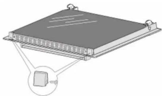
In order to obtain easier access to the oven chamber for cleaning, it is possible to remove the door. To do this, tilt the safety catch part of the hinge upwards. Close the door lightly, lift and pull it out towards you. In order to fit the door back on to the oven, do the inverse. When fitting, ensure that the notch of the hinge is correctly placed on the protrusion of the hinge holder. After the door is fitted to the oven, the safety catch should be carefully lowered down again. If the safety catch is not set it may cause damage to the hinge when closing the door.

Removal Of The Internal Glass Panel
Unscrew and unfasten the plastic latch that is in the corner at the top of the door.
Next take out the glass from the second blocking mechanism and remove.
After cleaning, insert and block the glass panel, and screw in the blocking mechanism.
natural_image
Diagram of a rectangular electronic device with ventilation grilles and a close-up inset showing a small component (no text or symbols)WARRANTY
1.1 In this warranty:
1.1.1 Australian Consumer Law means the law as set out in Schedule 2 of the Competition and Consumer Act 2010;
1.1.2 Company means GSM Sales Pty Ltd ABN 53 007 682 475 of 142-144 Fullarton Road, Rose Park SA 5067. Telephone 08 8122 2390. Email admin@gsmsales.com.au
1.1.3 Consumer means a “consumer” as that term is defined in Section 3 of the Australian Consumer Law as the original purchaser of a Bellini product;
1.1.4 Consumer Guarantees means the guarantees under the Australian Consumer Law;
1.1.5 You means the Consumer.
1.2 Nothing in this warranty affects any person's rights under the Australian Consumer Law. The benefits to any Consumer under this warranty are in addition to the rights and remedies available under any Consumer Guarantees.
1.3 Subject to the other clauses of this warranty, the Company warrants to the Consumer that the Bellini product will be free of manufacturing defects and will perform to the Company's specifications.
1.4 The benefit of this warranty extends only to the Consumer as original purchaser of a Bellini product which is installed in a residential property.
1.5 This warranty commences on the date of purchase of the Bellini product by the Consumer and continues for the benefit only of the Consumer until the expiry of two (2) years (Warranty Period).
1.6 If within the Warranty Period a manufacturing defect is discovered in the Bellini product or it fails to perform to the Company's specifications as a result of some defect in materials, components or workmanship (Defect) then the Company will, at its option, repair the Bellini product or supply a replacement Bellini product free of charge. A replacement Bellini product may differ from the original product purchased by the Consumer.
1.7 This warranty will not apply to any Bellini product:
1.7.1 Installed by any person other than a qualified tradesperson; or
1.7.2 Subjected to misuse, neglect, negligence or accidental damage; or
1.7.3 Operated in any way contrary to any operating or maintenance instructions; or
1.7.4 Improperly handled, installed or maintained; or
1.7.5 Altered or modified prior to or after installation; or
1.7.6 Damaged directly or indirectly by power surges, electrical storm damage or connection to incorrect power supply
The Australian Consumer Law requires the inclusion of the following statement
with this warranty:
Our goods come with guaranteed that cannot be excluded under the Australian Consumer Law. You are entitled to a replacement or refund for a major failure and for compensation for any other reasonably foreseeable loss or damage. You are also entitled to have the goods repaired or replaced if the goods fail to be of acceptable quality and the failure does not amount to a major failure.
IN ORDER TO MAKE A CLAIM UNDER THIS WARRANTY THE CONSUMER MUST CALL 1300 373 199 (AUSTRALIA) OR 0508 123 108 (NEW ZEALAND) TO CONNECT TO THE NEAREST AUTHORISED CENTRE
1.8 You must provide proof of your purchase of the Bellini product and the date of purchase in order to obtain the benefit of this warranty.
1.9 If you live outside the service area of the Company or one of its service agents, this warranty does not cover the cost of transport of the Bellini product for service nor the service agent's traveling costs to and from your home.
1.10 If you are required to transport the Bellini product to the Company or its service agent, you must ensure it is safely disconnected by a qualified tradesman and securely packed and insured. The Company does not accept any responsibility for loss or damage of the Bellini product prior to it being received by the Company or its service agent.
1.11 You will be responsible for all costs of returning a Bellini product to the Company and for redelivery of the Bellini product by the Company (whether it is the original or a repaired and/or a replacement Bellini product) and for any other expenses you incur in claiming under this warranty.
1.12 The Company or its service agent will examine any Bellini product and if the Company determines that it is defective through no fault of the Owner and is otherwise undamaged, the Company will repair or replace the Bellini product in accordance with this warranty.
DO NOT SEND IN THIS WARRANTY
Fill out the following details and file with your purchase invoice.
RETAIN & FILE WITH YOUR RECEIPT
Your Purchase Receipt/Invoice is proof of date of purchase. If you are unable to establish the date of purchase, or if the fault is not covered by this warranty, or if the product is found to be in working order, you will be required to bear all service call charges.
GSM Sales Pty Ltd reserves the right to discontinue items, modify designs and change specifications without incurring obligation.
Whilst every effort is made to ensure that descriptions, specifications and other information in this publication is correct, no warranty is given in respect thereof and the company shall not be liable for any errors therein.
Purchased from:
Co. Name:
Address:
Date of Purchase:
Serial number:
NOTE: Consistent with our continuing product development policy, improvements may have been made which render the contents of this packaging slightly different to that shown.
FOR WARRANTY SERVICE CALL 1300 373 199 (AUSTRALIA) OR 0508 123 108 (NEW ZEALAND) TO CONNECT YOU TO THE NEAREST AUTHORISED SERVICE CENTRE

Gerard Sourcing & Manufacturing
GSM Sales Pty Ltd.
The GSM Sales Pty Ltd. Group of Companies has a policy of continual improvement throughout the product range. As such the unit contained within may differ slightly from the unit illustrated on the pack.
MADE IN CHINA for the GSM Sales Pty Ltd. Group of Companies

N1028


- INTRODUCTION AND SAFETY WARNINGS
- WARNINGS:
- OPERATING INSTRUCTIONS
- LIGHTING THE BURNER
- BURNER AND UTENSIL CHOICE
- CLEANING INSTRUCTIONS
- GENERAL
- STAINLESS STEEL
- TRIVETS (UTENSIL SUPPORTS)
- BURNERS
- TROUBLESHOOTING
- INSTALLATION
- MINIMUM CLEARANCES:
- GAS and ELECTRICAL CONNECTION LOCATIONS and OVERALL DIMENSIONS:
- ELECTRICAL CONNECTION:
- GAS CONNECTION:
- SETTING THE GAS PRESSURE:
- TEST FOR CORRECT OPERATION:
- GAS CONVERSION INSTRUCTIONS:
- WARRANTY
- In this warranty:
- DO NOT SEND IN THIS WARRANTY
- RETAIN & FILE WITH YOUR RECEIPT
- FOR WARRANTY SERVICE CALL 1300 373 199 (AUSTRALIA) OR 0508 123 108 (NEW ZEALAND) TO CONNECT YOU TO THE NEAREST AUTHORISED SERVICE CENTRE
- 60cm Built In Oven
- Installation and User manual
- Content
- Important Safety Instructions
- General Warnings
- Child Safety
- Installation, Cleaning & Servicing
- ◆ THIS APPLIANCE MUST BE EARTHED.
- Oven
- Grill
- Environmental Hints
- Product Description
- Model BO6602X-1, BO6602X-1F
- Installation
- WARNING!
- Use An Authorized Person
- This Appliance Must Be Properly Earthed
- CAUTION!
- Connect power supply cord
- Start Using Your Over
- Preparing Your Oven
- BO610CX-1, BO610CX-1F, BO610CX-2, BO610CX-2F
- Select the functions ( All Models )
- Select the temperature ( All Models )
- Work With Minute Timer
- Model BO610CX-1, BO610CX-1F, BO610CX-2, BO610CX-2F
- O'Clock Time Setting
- Cooking Duration Setting
- Cooking End Time Setting
- Delayed Start Cooking Setting
- To Check or Canceling Settings
- Troubleshooting
- Maintenance and Cleaning
- Glass
- Replacement Of The Oven Light Bulb
- Door Removal
- Removal Of The Internal Glass Panel
Brand : Bellini
Model : BP260EG
Category : Cooker