
Springboro - Uncategorized Backyard Discovery - Free user manual and instructions
Find the device manual for free Springboro Backyard Discovery in PDF.


| Type de produit | Playset (jungle gym) with swing, slide, monkey bars, glider, and clubhouse |
| Marque | Backyard Discovery |
| Modèle | Springboro |
| Matériau | Chinese cedar wood (naturally bug, decay, and rot resistant; chemical free) |
| Âge recommandé | 3 to 10 years |
| Capacité maximale | 9 children; up to 150 lbs per child for individual activities, 120 lbs for multiple child activities |
| Zone de sécurité requise | At least 6 ft (1.8 m) from any structure or obstruction; recommend 6 ft perimeter around and above |
| Surface de jeu recommandée | Loose fill material (wood chips, bark mulch, sand, gravel) with minimum 9 inches depth for equipment up to 8 ft high |
| Hauteur de chute maximale | Varies by surfacing; up to 12 ft for some materials (see manual for specific heights) |
| Dimensions approximatives (assemblé) | Not specified in manual; typical for this model: about 12 ft x 10 ft x 8 ft (estimate based on component sizes) |
| Poids (approx.) | Not specified; estimated 300-400 lbs (typical for wooden playsets) |
| Fonctions principales | Two belt swings, one glider, one 8 ft slide, monkey bars, clubhouse with bay window, picnic table, and ladder |
| Entretien | Stain annually; tighten hardware twice a month during play season; inspect wood monthly; lubricate moving parts |
| Assemblage | Requires 2 adults; estimated assembly time not specified (typically 6-10 hours) |
| Garantie | 1 year replacement on all parts for manufacturer defects; 5 year prorated warranty on wood against rot and decay |
| Pièces détachées et réparabilité | Parts orderable via swingsetsonline.com; most components are replaceable; includes hardware and wood parts |
| Outils requis (non inclus) | Cordless drill, rubber mallet (optional), tape measure, 3/8" drive ratchet with 1/2" sockets |
| Fixation au sol | Must be anchored with ground stakes (included) at 45° angle |
| Sécurité | Adult supervision required; do not attach ropes or chains not designed for equipment; use protective surfacing; check for rust, splinters, and loose hardware regularly |
| Nettoyage | Sand splinters as needed; clean with mild soap and water; avoid harsh chemicals |
Frequently Asked Questions - Springboro Backyard Discovery
User questions about Springboro Backyard Discovery
0 question about this device. Answer the ones you know or ask your own.
Ask a new question about this device
Download the instructions for your Uncategorized in PDF format for free! Find your manual Springboro - Backyard Discovery and take your electronic device back in hand. On this page are published all the documents necessary for the use of your device. Springboro by Backyard Discovery.
USER MANUAL Springboro Backyard Discovery
Owner's Manual & Assembly Instructions
MANUFACTURED BY: Backyard Discovery 3305 Airport Drive Pittsburg, KS 66762 800-856-4445
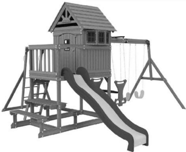
natural_image
3D rendering of a children's playground slide with a wooden cabin and climbing structure (no text or symbols)
GOCONFIGURE
Putting it all together for you
INSTALLATION
SERVICES
average 2 person assembly time

Before you begin
FOR QUICK &
EASY ASSEMBLY
STOP
PARE
Missing A Part?
CALL US BEFORE GOING
BACK TO THE STORE!
The store where you made your purchase
does not stock parts for this item.
If you have assembly questions or if you need parts,
whether they are missing or damaged
Call Toll-Free Help Line or visit www.swingsetsonline.com
Owner's Manual Play Set
Dear Customer:
Please read entire booklet completely before beginning the assembly process.
Equipment is recommended for use by children 3 to 10 years of age. Structures are not intended for public use. The Company does not warranty any of its residential structures subjected to commercial use such as: Daycare, Preschool, Nursery School, Recreational Park, or any similar Commercial Application.

WARNING: This Symbol points out important safety instructions which, if not followed, could endanger the personal safety of yourself and your children and/or damage your property. You MUST read and follow all instructions in this manual before attempting to use this playcenter.

WARNING: Children must NOT use this playcenter until unit has been completely assembled and inspected by an adult to insure set has been properly installed and anchored.
Please follow all recommendations below. Failure to do so may result in the warranty being void and/or safety violations that could result in serious injury. This manual contains helpful information concerning Assembly Preparation, Installation Procedure, and Required Maintenance. Always keep the safety of your children in mind as your play structure is being built and as your children play on the set. Before your children play on the set please review the Operation Instructions with them to help ensure their safety.
PLEASE RETAIN THESE INSTRUCTIONS FOR FUTURE REFERENCE. KEEP THEM IN A SAFE PLACE WHERE YOU CAN REFER TO THEM AS NEEDED, IN ORDER TO PROVIDE YOU WITH THE MOST EFFICIENT SERVICE. IT IS REQUIRED THAT YOU PROVIDE US WITH THE PART NUMBERS WHEN ORDERING PARTS.
For Your Records:
Please take time and fill out the information below. This information will be needed for warranty issues.
Where Purchased:
Date of Purchase:
Installation Date:
Staple Receipt Here

Owner's Manual Play Set
Please refer to the Assembly section of the Assembly Manual for Maximum Fall Height.
Positioning Your Playcenter
- The Playcenter is designed to be installed on a level surface by an Adult with an Adult helper. Place in a flat area of your yard to minimize ground preparation.
- Choose a level location for the equipment. This can reduce the likelihood of the play set tipping over and loose-fill surfacing material washing away during heavy rains.
- Place the equipment not less than 6 ft (1.8 m) from any structure or obstruction such as a fence, garage, house, overhanging branches, laundry lines, or electrical wires.
- Provide enough room so that the children can use the equipment safely. For example, for structures with multiple play activities, a slide should not exit in front of a swing.
- It is a good idea to place your Playcenter in an area that is convenient for adults to watch children at play.
- Create a site free of obstacles that could cause injuries – such as low overhanging tree branches, overhead wires, tree stumps and/or roots, large rocks, bricks and concrete. Additional suggestions in the Suggested Playground Surfacing Section.
- Do not build your playset on top of surfacing material.
- Locate bare metal platforms and slides out of direct sunlight to reduce the likelihood of serious burns. A slide that faces north will receive the least direct sunlight.
- Separate active and quiet activities from each other. For example, locate sandboxes away from swings or use a guardrail or barrier to separate the sandbox from the movement of the swings.
Suggested Playground Surfacing
☐ Do not install home playground equipment over concrete, asphalt, packed earth, grass, carpet, or any other hard surface. A fall onto a hard surface can result in serious injury to the equipment user.
☐ Do not install loose fill surfacing over hard surfaces such as concrete or asphalt.
☐ Shredded bark mulch, wood chips, fine sand and fine gravel, are added as shock absorbing materials after assembly. If used properly these materials can absorb some of the impact of a child's fall.
☐ All surface material should extend a minimum of 6 feet in all directions around the play area.
☐ Do not apply playground surfacing until after the unit is completely constructed. Playset should not be built on top of surfacing.
- Use containment such as diagonal out around the perimeter and/or lining the perimeter with landscape
Owner's Manual Play Set
The following chart explains the fall height in feet from which a life threatening head injury would not be expected
Critical Heights in feet (m) of Tested Materials
| Material Uncompressed Depth Compressed Depth | ||||
| 6" (152mm) 9" (228mm) | 12" (304mm) | to 9" (228mm) | ||
| Wood Chips 7' (2.13m) 10' (3.05m) | 11' (3.35m) | 10' (3.05m) | ||
| Double-Shredded bark mulch | 6' (1.83m) 10' (3.05m) | 11' (3.35m) | 7" (2.13m) | |
| Engineered Wood Fibers 6' (1.83m) 7' (2.13m) >12' (3.66m) | 6' (1.83m) | |||
| Fine Sand 5' (1.52m) 5' (1.52m) 9' (2.74m) 5' (1.52m) | ||||
| Coarse Sand 5' (1.52m) 5' (1.52m) 6' (1.83m) 4' (1.22m) | ||||
| Fine Gravel | 5' (1.52m) | 7' (2.13m) | 10' (3.05m) | 6' (1.83m) |
| Medium Gravel | 5' (1.52m) 5' (1.52m) 6' (1.83m) 5' (1.52m) | |||
| Shredded Tires* | 10-12' (3.0-3.6m) | N/A | N/A | N/A |
*This data is from tests conducted by independent testing laboratories on a 6-inch depth of uncompressed shredded tire samples produced by four manufacturers. The tests reported critical heights, which varied from 10 feet to greater than 12 feet. It is recommended that persons seeking to install shredded tires as a protective surface request test data from the supplier showing the critical height of the material when it was tested in accordance with ASTM F1292.
Operating Instructions:

NOTE: Your children's safety is our #1 concern. Observing the following statements and warnings reduces the likelihood of serious or fatal injury. Please review these safety rules regularly with your children.
- This Playcenter is designed for specific number of occupants whose combined weight should not exceed a designated weight on the elevated floor or the swing area, the total Unit capacity is outlined in the Basic Setup Dimensions section of instruction manual. The maximum fall height and recommended play area is also available in the Basic Setup Dimensions section of the manual for the specific unit.
- On-site adult supervision is required.
- Instruct children not to walk close to, in front of, behind, or between moving swings or other moving playground equipment.
Owner's Manual Play Set
- Verify that any suspended climbing ropes, chain, or cable are secured at both ends and that they cannot be looped back on it.
- Instruct children not to attach items to the playground equipment that are not specifically designed for use with the equipment, such as, but not limited to, jump ropes, clothesline, pet leashes, cables and chain as they may cause a strangulation hazard.
- Instruct children to never wrap their legs around swing chain.
- Instruct children to never slide down the swing chain.
- Instruct children to remove their bike or other sports helmet before playing on playground equipment.
Maintenance Instructions:
At the beginning of each play season:
- Tighten all hardware.
- Lubricate all metallic moving parts per manufacturer's instructions.
- Check all protective coverings on bolts, pipes, edges, and corners. Replace if they are loose, cracked, or missing.
- Check all moving parts including swing seats, ropes, cables, and chains for wear, rust, or other deterioration. Replace as needed.
- Check metal parts for rust. If found, sand and repaint using a non Lead-based paint meeting the requirements of 16 CFR 1303.
- Check all wood members for deterioration and splinters. Sand down splinters and replace deteriorating wood members.
- Reinstall any plastic parts, such as swing seats or any other items that were removed for the cold season.
- Rake and check depth of loose fill protective surfacing materials to prevent compaction and to maintain appropriate depth. Replace as necessary.
Twice a month during play season:
- Tighten all hardware.
Additional Maintenance:
- Check the swing beam and hardware every two weeks due to wood expansion and contraction. It is particularly important that this procedure be followed at the beginning of each season.
- Inspect wood parts monthly. The grain of the wood sometimes will lift in the dry season causing splinters to appear. Light sand may be necessary to maintain a safe playing environment. Treat your playset with stain regularly, to help prevent severe checking/splitting and other weather damage.
- A waterbourne transparent stain has been applied to your playset. This is done for color only. Once or twice a year, depending on your climate conditions, you must apply some type of protection (sealant) to the wood of your unit. Prior to the application of sealant, lightly sand any "rough" spots on your playset. Please note this is a requirement of your warranty.
- Assembling and maintaining the playset on a level location is very important. As your children play, your playset will slowly dig its way into the soil, and it is very important that it settles evenly. Make sure the playset is level and true one each year or at the beginning of each play season.
Disposal Instructions:
When the Playcenter use is no longer desired, it should be disassembled and disposed of in such a way that no unreasonable hazards will exist at the time the unit is discarded.
Third Party Assembly:
Customer may, in their sole discretion, elect to use a third party person or service to assemble this product. Backyard Discovery assumes no responsibility or liability for any charge incurred by the Customer for any assembly services'. Please see our warranty for more information about damaged and missing part replacement
APPENDIX A
Information on Playground Surfacing Materials:
The following information is from the United States Consumer Product Safety Commission's Information Sheet for playground surfacing material; also see the following website for additional information: www.cpsc.gov/cpscpub/pubs/323.html.
X3. SECTION 4 OF THE CONSUMER PRODUCT SAFETY COMMISSION'S OUTDOOR HOME PLAYGROUND SAFETY HANDBOOK ^2
X3.1 Select Protective Surfacing—One of the most important things you can do to reduce the likelihood of serious head injuries is to install shock-absorbing protective surfacing under and around your play equipment. The protective surfacing should be applied to a depth that is suitable for the equipment height in accordance with ASTM Specification F 1292. There are different types of surfacing to choose from; whichever product you select, follow these guidelines:
X3.1.1 Loose-Fill Materials:
X3.1.1.1 Maintain a minimum depth of 9 inches of loose-fill materials such as wood mulch/chips, engineered wood fiber (EWF), or shredded/recycled rubber mulch for equipment up to 8 feet high; and 9 inches of sand or pea gravel for equipment up to 5 feet high. NOTE: An initial fill level of 12 inches will compress to about a 9-inch depth of surfacing overtime. The surfacing will also compact, displace, and settle, and should be periodically refilled to maintain at least a 9-inch depth.
X3.1.2 Use a minimum of 6 inches of protective surfacing for play equipment less than 4 feet in height. If maintained properly, this should be adequate. (At depths less than 6 inches, the protective material is too easily displaced or compacted.) NOTE: Do not install home playground equipment over concrete, asphalt, or any other hard surface. A fall onto a hard surface can result in serious injury to the equipment user. Grass and dirt are not considered protective surfacing because wear and environmental factors can reduce their shock absorbing effectiveness. Carpeting and thin mats are generally not adequate protective surfacing. Ground level equipment such as a sandbox, activity wall, playhouse or other equipment that has no elevated play surface – does not need any protective surfacing.
X3.1.3 Use containment, such as digging out around the perimeter and/or lining the perimeter with landscape edging. Don't forget to account for water drainage.
X3.1.3.1 Check and maintain the depth of the loose-fill surfacing material. To maintain the right amount of loose-fill materials, mark the correct level on play equipment support posts. That way you can easily see when to replenish and/or redistribute the surfacing.
X3.1.3.2 Do not install loose-fill surfacing over hard surfaces such as concrete or asphalt.
X3.1.4 Poured-In-Place Surfaces or Pre-Manufactured Rubber Tiles — You may be interested in using surfacing other than loose-fill materials – like rubber tiles or poured-in-place surfaces.
X3.1.4.1 Installations of these surfaces generally require a professional and are not "do-it-yourself" projects.
X3.1.4.2 Review surface specification before purchasing this type of surfacing. Ask the installer/manufacturer for a report showing that the product has been tested to the following safety standard: ASTM F 1292 Standard Specification for Impact Attenuation of Surfacing Materials within the Use Zone of Playground Equipment. This report should show the specific height for which the surface is intended to protect against serious head injury. This height should be equal to or greater than the fall height – vertical distance
Play Set Assembly Manual FAQs:
- Does the area for the playset need to be level?
Yes. Backyard Discovery recommends the playset be positioned on a flat level area for maximum safety and durability. The stakes provided should be used to secure it firmly to the ground.
- What size area is recommended for the playset?
Backyard Discovery recommends at least a 6' (six foot) perimeter around and above the playset for maximum safety.
- What age range is appropriate for the playsets?
Backyard Discovery playsets are recommended for children ages 3 – 10 years.
- Is the wood treated with chemicals?
Backyard Discovery uses 100% Chinese Cedar wood which is naturally bug resistant, decay and rot resistant. To help ensure your child's safety, our wood is completely chemical free and we do not use pressure-treated wood. The stain we use is a top coat using a water-based product that is for appearance only.
- How often should the playset be stained?
Backyard Discovery recommends the playset be stained once each year. A water or oil based stain can be used at the customer's discretion.
- Why does it seem that my swing set is developing cracks?
Wood is a natural material; no two pieces are exactly alike. Each piece has its own characteristics and personality and reacts differently to climate changes. When any wood product is exposed to the elements, it develops "wood checks". A check is the radial separation of the wood fibers running with the grain of the wood. These are caused by the varying temperature and moisture conditions. A check is not a crack – it does not affect the strength or durability of the wood or structural integrity of the play set.
- Do Backyard Discovery playsets come with a warranty?
Yes. All Backyard Discovery products carry a 1-year replacement warranty on all parts for manufacturer's defect. Our wood carries a 5 year warranty on rot and decay as well. Please see warranty details for more information.
- What is the best way to get started assembling the playset?
Backyard Discovery recommends taking all the parts out of the boxes and arranging them by part number before you begin any assembly. This will not only allow faster assembly, but will also identify any parts that may be missing or damaged so they can be replaced before assembly. If parts are missing or need replacement, go to www.swingsetsonline.com/support.aspx and follow the prompts to order them. Next, read the assembly manual and get the tools ready for the job as recommended in the manual. If the
Tools Required for Installation:
(These are the tools that are generally required for assembly of our outdoor products. These tools are not included with the outdoor product purchase.)
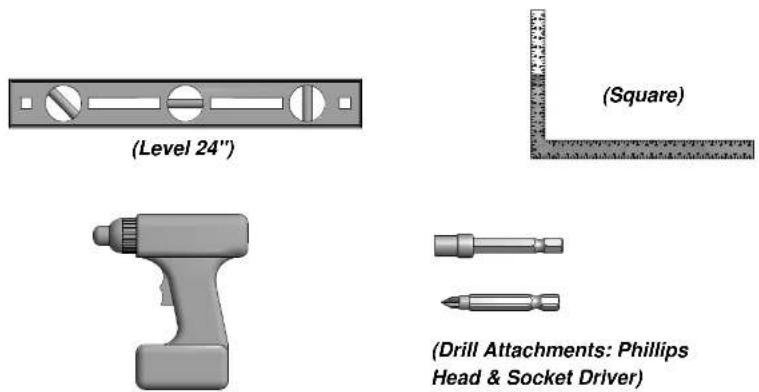
(Cordless Drill or Electric Drill)
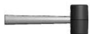
(Rubber Mallet - Optional)
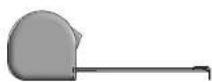
(Tape Measure)
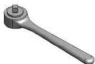
(3/8" Drive Ratchet, 1/2" STD Sockets 1/2" Deep Sockets)
Basic Setup Dimensions
Place the set on level ground, not less than 6 ft [2 m] from any structure or obstruction such as a fence, garage, house, overhanging branches, laundry lines, or electrical wires.
![Safe Play Zone 28'- 1/2" [8.5 m] 27'-6" [8.4 m] 15'-6" [4.7 m] 6' [1.8 m] 16'- 1/2" [4.9 m] 6' [1.8 m]](/content/2026/05/927382/images/8b64a1e286cc3595dad2e519d37b16e17d984eef5eeb1e8f4921446e8b38af03.jpg)
General Information:
Your set has been designed and engineered for children only and for residential use only. A maximum of 150 lbs. per child is recommended for play activities designed for individual use. A maximum of 120 lbs. per child is recommended for play activities designed for multiple child use. A maximum of 9 children is recommended for this swing set.
![6'-3 1/2" [1.9 m] 9'-3 1/2" [2.8 m]](/content/2026/05/927382/images/94fb37504cd108373f2da965444f81e36b44b34eba13af63c353932f70756ac8.jpg)
Parts Identification
Wood Components
(NOT TO SCALE)
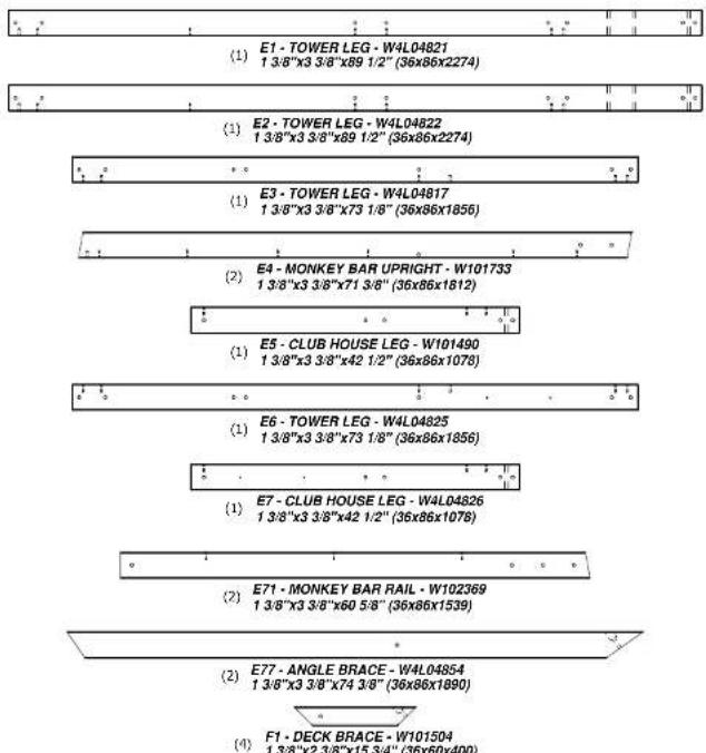
Parts Identification
Wood Components (NOT TO SCALE)
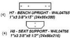
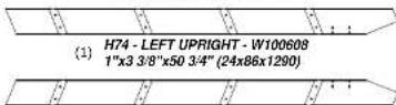
(1) H75 - RIGHT UPRIGHT - W100609 1"x3 3/8"x50 3/4" (24x86x1290)
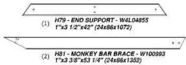

(1) H82 - MONKEY BAR GROUND BOARD - W100994 1"x3 3/8"x70 3/8" (24x86x1786)


(2) K1·BASE BOARD·W4L04815 5/8"x5 1/4"x84 3/8" (16x134x2144)

(2) K2 - BASE BOARD - W101452 5/8"x5 1/4"x40 3/8" (16x134x1024)
Parts Identification
Wood Components
(NOT TO SCALE)
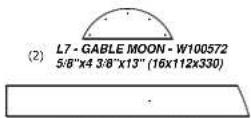
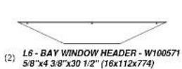
(2) L6 - BAY WINDOW HEADER - W100571 5/8"x4 3/8"x30 1/2" (16x112x774)
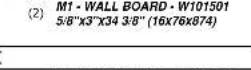
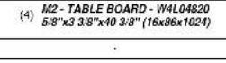
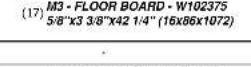
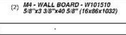
Parts Identification
Wood Components
(NOT TO SCALE)

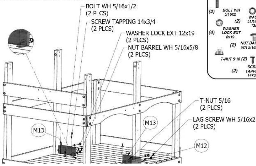
(2) M13 - WALL RAIL - W101500 5/8"x3 3/8"x8 1/2" (16x86x216)

(1) M14 - WALL RAIL - W102372 5/8"x3 3/8"x40 3/8" (16x86x1024)

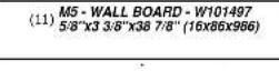
(8) M15 - WALL BOARD - W101506 5/8"x3 3/8"x3 1/2" (16x86x88)

(3) M16 - WALL BOARD - W101732 5/8"x3 3/8"x16 1/4" (16x86x412)

(9) M17 - WALL BOARD - W101493 5/8"x3 3/8"x21 3/8" (16x86x542)

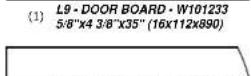
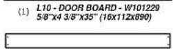
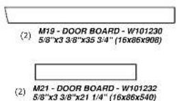
(2) M19 - DOOR BOARD - W101230 5/8"x3 3/8"x35 3/4" (16x86x908)

(2) M21 - DOOR BOARD - W101232 5/8"x3 3/8"x21 1/4" (16x86x540)

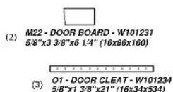
(2) M22 - DOOR BOARD - W101231 5/8"x3 3/8"x6 1/4" (16x86x160)

(1) M77 - SLIDE BRACE - W100544 5/8"x3 3/8"x17 1/4" (16x86x438)

(2) M78 - CENTER SLIDE BRACE - W100545 5/8"v3 9/8"v17 1/4" /16v86v4281
Parts Identification
Wood Components
(NOT TO SCALE)

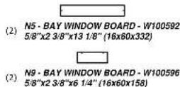
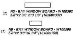
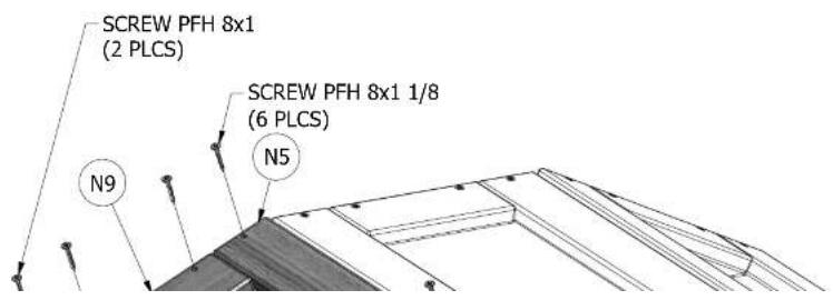
(6) N5 - BAY WINDOW BOARD - W100592 5/8"x2 3/8"x13 1/8" (16x60x332)

(2) N6 - GABLE BOARD - W100593 5/8"x2 3/8"x13" (16x60x330)

(4) N7·GABLE BOARD·W100594 5/8"x2 3/8"x8" (16x60x202)

(2) N8 - WALL BOARD SUPPORT - W100595 5/8"x2 3/8"x6 3/4" (16x60x170)

(6) N9 - BAY WINDOW BOARD - W100596 5/8"x2 3/8"x6 1/4" (16x60x158)

(1) N11·DOOR STOP-W101236 5/8"x2 3/8"x2" (16x60x51)

(3) O1-DOOR CLEAT-W101234 5/8"x1 3/8"x21" (16x34x534)

(4) Q1 - BENCH SEAT - W4L04816 1"x4 3/8"x42 1/2" (24x112x1078

(14) R1 - ROOF BOARD - W101503 3/4"x5 1/2"x42 1/2" (18x140x1081)

(1) SB74 - SWING BEAM EXTENDED 2"x5 1/4"x89 1/2" (50x134x2274)
Parts Identification
Hardware
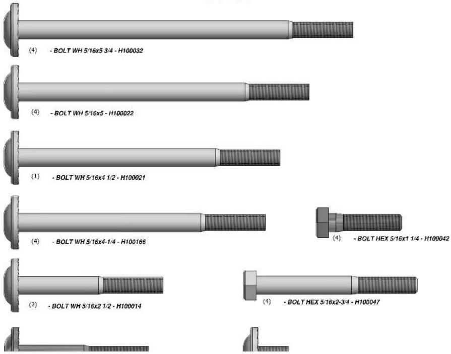
Parts Identification
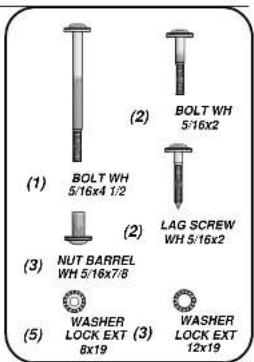
Hardware

(26) - SCREW PFH 8x3 - H100092

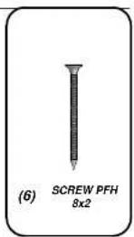
(37) - SCREW PFH 8x2 - H100111
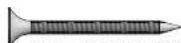
(199) - SCREW PFH 8x1-1/2" - H100086
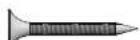
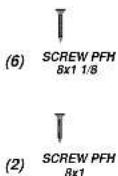
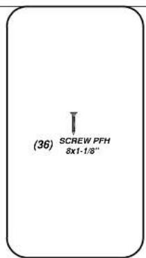
(261) - SCREW PFH 8x1-1/8" - H100088
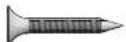
(4) - SCREW PFH 8x1 - H100085
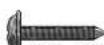
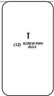
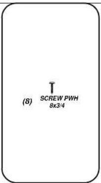
(26) - SCREW PWH 8x3/4 - H100070

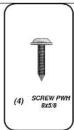
(17) - SCREW PWH 8x5/8 - H100128
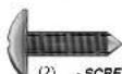
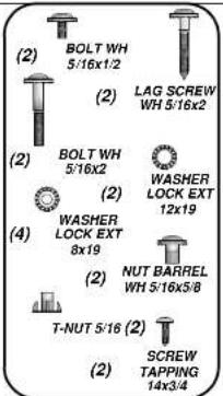
(2) - SCREW TAPPING 14x3/4 - H100083
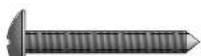
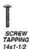
(22) - SCREW TAPPING 14x1-1/2 - H100109


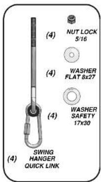
(4) - WASHER SAFETY 17x30 - H100103

(26) · WASHER FLAT 8x27 · H100105

(11) - WASHER FLAT 9x18 - H100106

(11) - WASHER LOCK INT 8x15 - H100108

(4) - WASHER SPLIT 5/16 - H100095

Parts Identification
Hardware
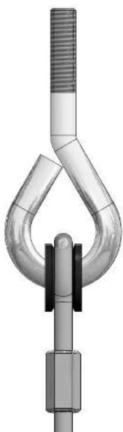
natural_image
Mechanical clamp or hook assembly with metallic components and a central shaft (no text or symbols visible)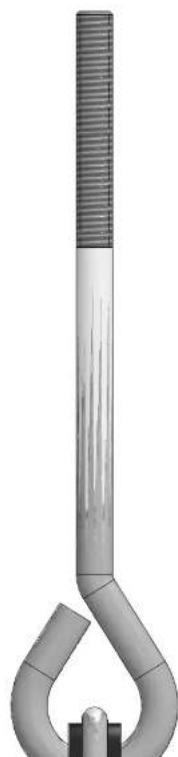
natural_image
3D rendered image of a metallic hook with a textured top and curved base (no text or symbols)Parts Identification
Accessories
(NOT TO SCALE)
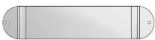
(2) FB - SWING SEAT YELLOW - A100070

(4) DG-CHAIN GREEN 38.5" - A100015
natural_image
3D rendered curved surface with a black line, no text or symbols visible
Parts Identification
Accessories
(NOT TO SCALE)
natural_image
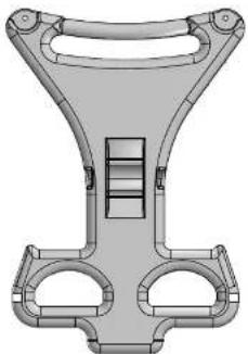
Technical illustration of a mechanical component with no visible text or symbols(2) DJ - GLIDER ARM LIGHT GREEN - A100021
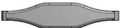
(1) DN - GLIDER SEAT DARK GREEN - A100025

(6) EC - METAL RUNG 559 - A100045

natural_image
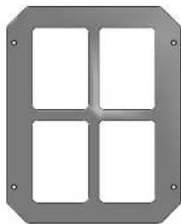
Exterior view of a four-segment LED display panel (no text or symbols)(6) GK-WINDOW FRAME 216x267 BYD GREEN-A100146

natural_image
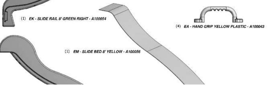
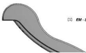
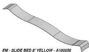
3D model of a curved metallic object with segmented sections, labeled 'EM - SLIDE BED 6' YELLOW - A100056' (no other text or symbols)
(1) M77 - SLIDE BRACE - W100544 5/8"x3 3/8"x17 1/4" (16x86x438)
SLIDE ASSEMBLY STEP 1

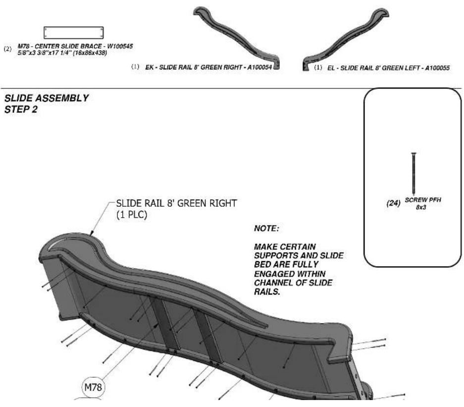
(2) M78 - CENTER SLIDE BRACE - W100545 5/8"x3 3/8"x17 1/4" (16x86x438)
(1) EL-SLIDE RAIL 8' GREEN LEFT-A100055

(1) H74 - LEFT UPRIGHT - W100608 1"x3 3/8"x50 3/4" (24x86x1290)
LADDER ASSEMBLY
STEP 1
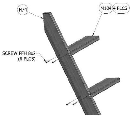
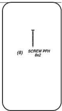

(1) H75 - RIGHT UPRIGHT - W1006 1"x3 3/8"x50 3/4" (24x86x1290)
LADDER ASSEMBLY
STEP 2
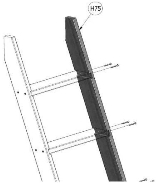
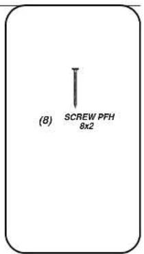
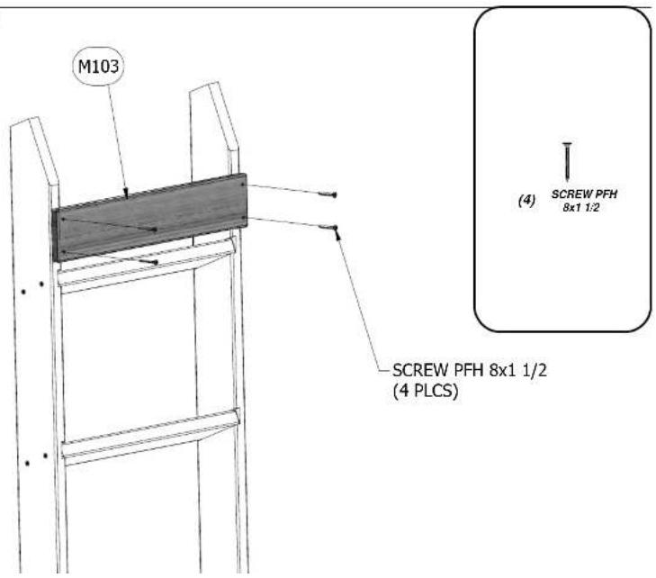
(1)

M103 - REAR SUPPORT - W102996
5/8"x3 3/8"x18 1/4"(16x86x462)
LADDER ASSEMBLY
STEP 3

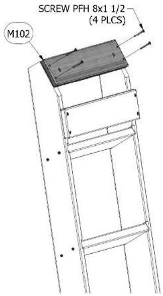
(1) M102 - ATTACHMENT BOARD - W4L04824 5/8"x3 3/8"x18 1/4" (16x86x462)
LADDER ASSEMBLY
STEP 4

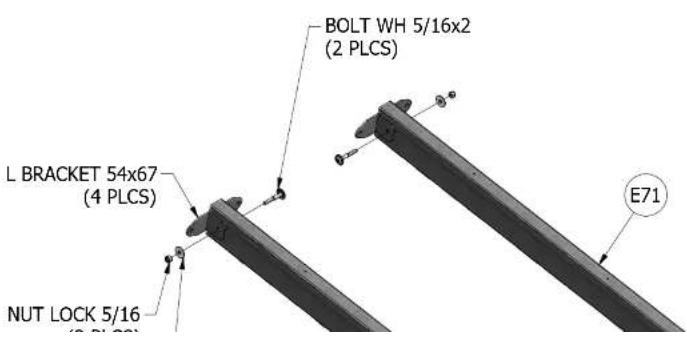
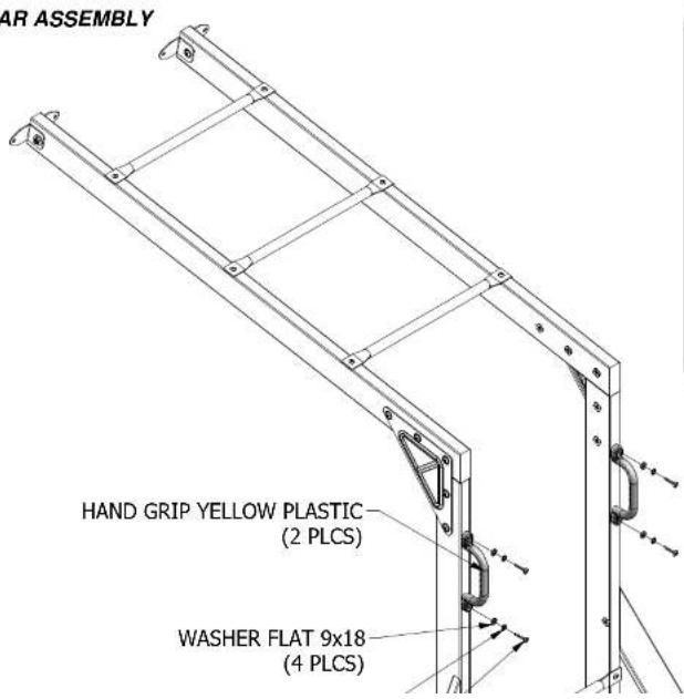
(2) E71 - MONKEY BAR RAIL - W102369 1 3/8"x3 3/8"x60 5/8" (36x86x1539)
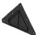
(4) EJ-L BRACKET 54x67-A100053

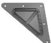
(2) QZ - TRIANGLE PLATE 100° 5 HOLE - A100294
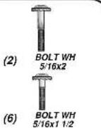
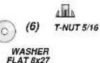
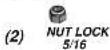
MONKEY BAR ASSEMBLY
STEP 1


(2) E4 - MONKEY BAR UPRIGHT - W101733 1 3/8"x3 3/8"x71 3/8" (36x86x1812)
MONKEY BAR ASSEMBLY
STEP 2
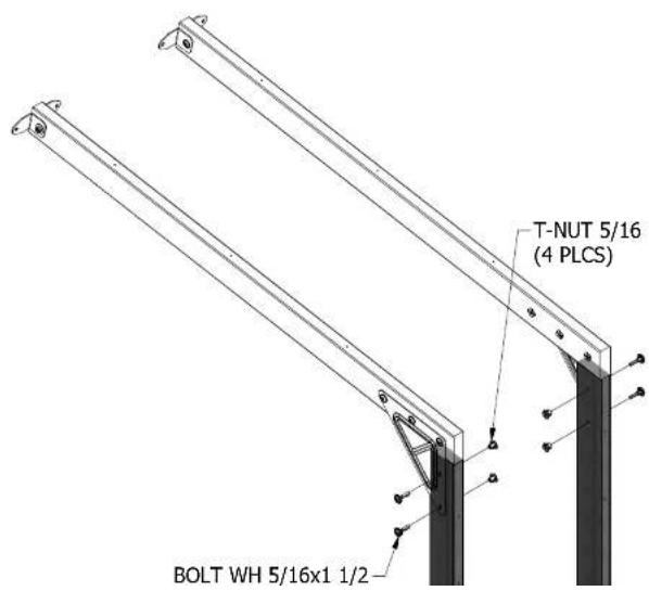


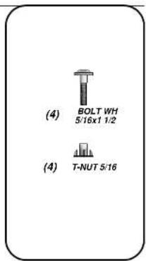

MONKEY BAR ASSEMBLY
STEP 5
(4)
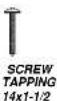
(4)

(4)


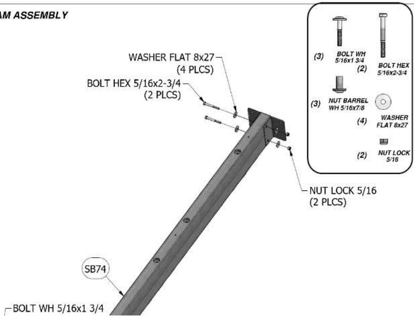
(1) SB74 - SWING BEAM EXTENDED - W102419 2"x5 1/4"x89 1/2" (50x134x2274)
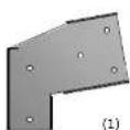
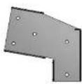
(1) TC - SWING BEAM EXTENSION BRACKET-RIGHT - A100326
(1) TB - SWING BEAM EXTENSION BRACKET-LEFT - A100325
(2) GD - L BRACKET 66x66x127 - A100140

SWING BEAM ASSEMBLY
STEP 1

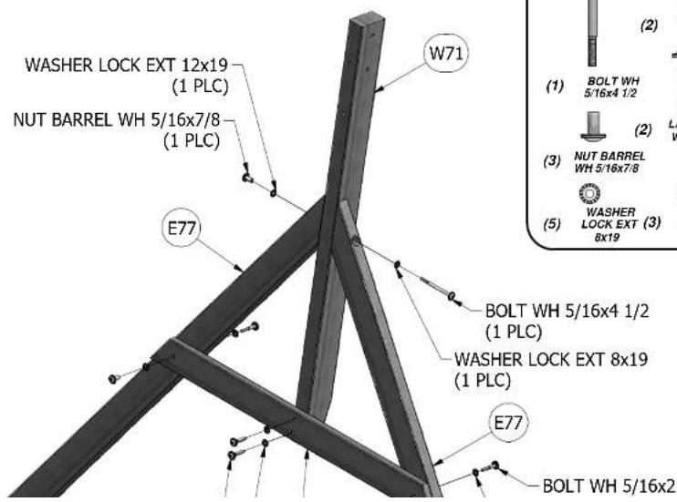
(1) W71 - SWING BEAM SUPPORT - W102420 2"x3 3/8"x49 5/8" (50x86x1260)

(1) H79 - END SUPPORT - W100992 1"x3 1/2"x42" (24x86x1072)

(2) E77 - ANGLE BRACE - W100991
1 3/8"x3 3/8"x74 3/8" (36x86x1890)
SWING BEAM ASSEMBLY
STEP 2
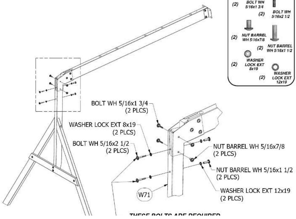
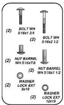
SWING BEAM ASSEMBLY
STEP 3
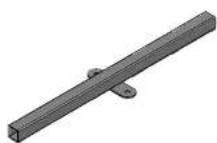

(4) EX - GLIDER BUSHING BYD GREEN - A100066
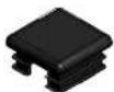
(4) EY - TUBING CAP GLIDER SUPPORT - A100067
(2) EW - GLIDER SUPPORT BYD GREEN - A100065
SWING BEAM ASSEMBLY
STEP 4
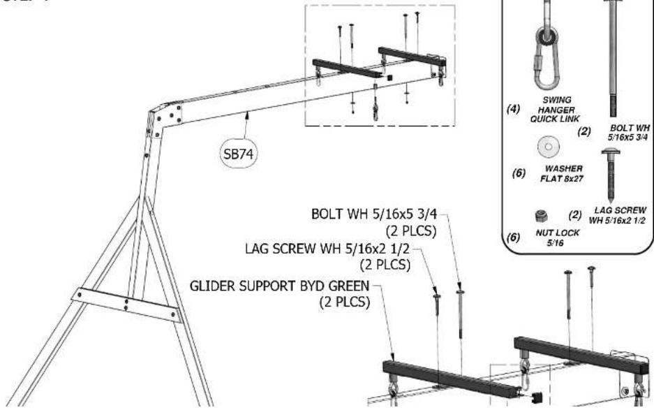
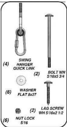
SWING BEAM ASSEMBLY
STEP 5
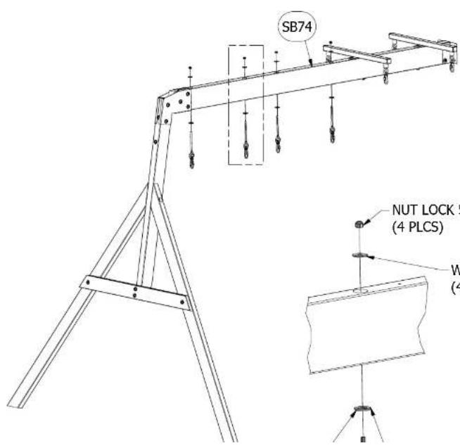
BAY WINDOW ASSEMBLY STEP 1
CENTER 'N9' BOARDS ON 'L6' BOARDS.
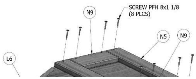
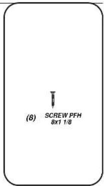
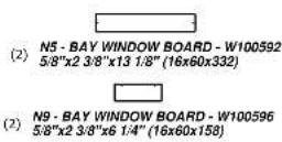
BAY WINDOW ASSEMBLY
STEP 2
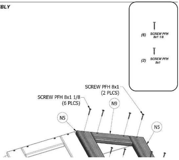
BAY WINDOW ASSEMBLY STEP 3
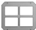
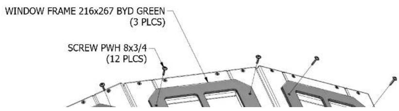
(3) GK-WINDOW FRAME 216x267 BYD GREEN-A100146
BAY WINDOW ASSEMBLY STEP 4
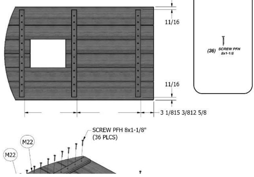
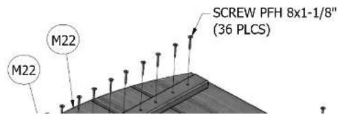
DOOR ASSEMBLY
STEP 1
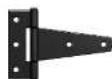
(2) HINGE - A100093
DOOR ASSEMBLY
STEP 2

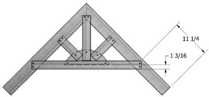
(4) H3 - ROOF RAFTER - W101502 1"x3 3/8"x34" (24x86x864)
(2) N3 - GABLE BOARD - W100590 5/8"x2 3/8"x31 1/2" (16x60x800)

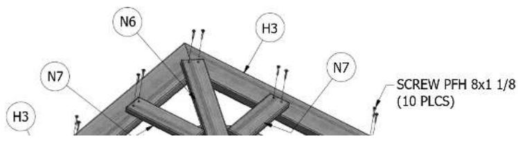
(2) N6 - GABLE BOARD - W100593 5/8"x2 3/8"x13" (16x60x330)

(2) L7 - GABLE MOON - W100572 5/8"x4 3/8"x13" (16x112x330)

(4) N7 - GABLE BOARD - W100594 5/8"x2 3/8"x8" (16x60x202)
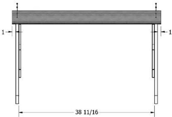
ROOF ASSEMBLY STEP 1
MAKE TWO GABLE END ASSEMBLIES.

(2) R1 - ROOF BOARD - W101503
3/4"x5 1/2"x42 1/2" (18x140x1081)
ROOF ASSEMBLY STEP 2
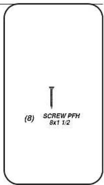
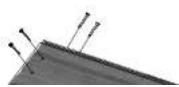

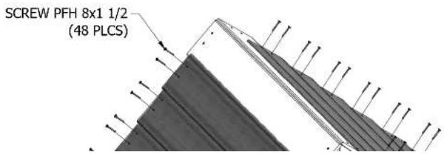
- SCREW PFH 8x1 1/2

(12) R1 - ROOF BOARD - W101503
3/4"x5 1/2"x42 1/2" (18x140x1081)
ROOF ASSEMBLY STEP 3
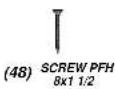
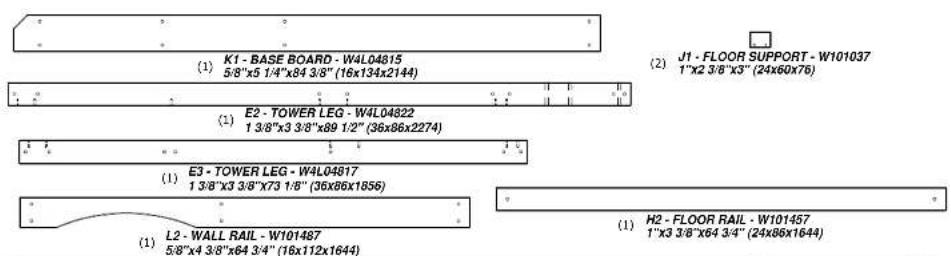

(2) K2 - BASE BOARD - W101452 5/8"x5 1/4"x40 3/8" (16x134x1024)

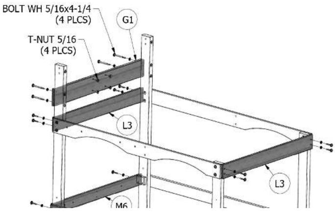
(1) M6 - FLOOR RAIL - W102373 5/8"x3 3/8"x40 3/8" (16x86x1024)

(1) MS - WALL RAIL - W101454 5/8"x3 3/8"x40 3/8" (16x86x1024)

(1) M14 · WALL RAIL · W102372 5/8"x3 3/8"x40 3/8" (16x86x1024)

(1) G1 - SWING BEAM MOUNT - W101495 1"x5 1/4"x40 3/8" (24x134x1024)

(2) L3 - WALL RAIL - W101489
5/8"x4 3/8"x40 3/8" (16x112x1024)
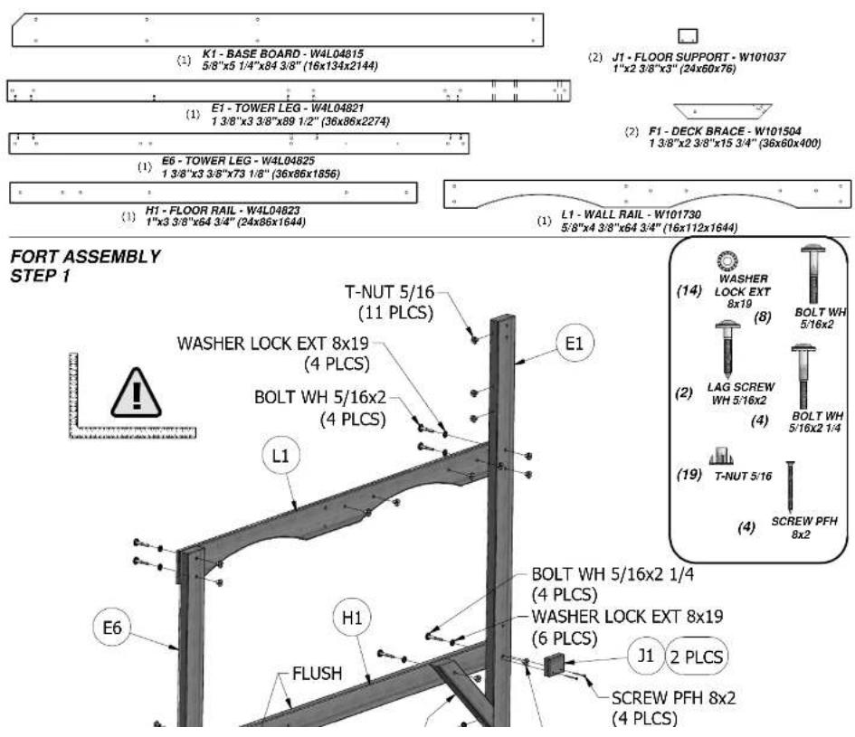
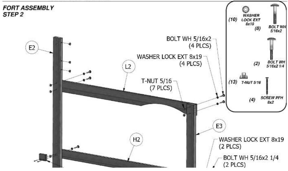
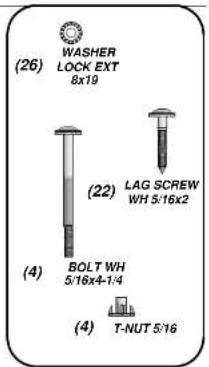
FORT ASSEMBLY
STEP 3
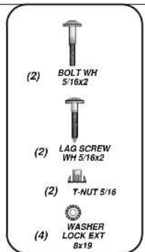
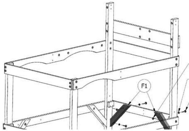
(2) F1 - DECK BRACE - W101504
1 3/8"x2 3/8"x15 3/4" (36x60x400)
FORT ASSEMBLY STEP 4

natural_image
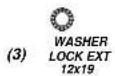
Technical line drawing of a structural frame with mounting brackets and support columns (no text or symbols)T-NUT 5/16 (2 PLCS) WASHER LOCK EXT 8x19 (4 PLCS) — BOLT WH 5/16x2 (2 PLCS)
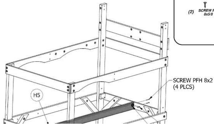
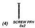
(1) H5 - FLOOR JOIST - W102374 1"x3 3/8"x64 3/4" (24x86x1644)
(1) SQ - "A" REVISION TAG - A100314
FORT ASSEMBLY
STEP 5



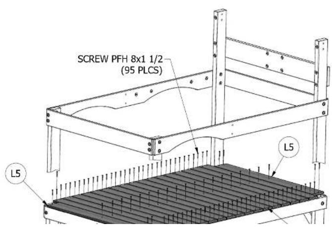
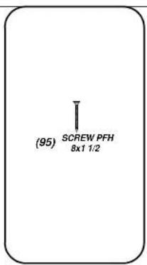
(17) M3 - FLOOR BOARD - W102375 5/8"x3 3/8"x42 1/4" (16x86x1072)

(2) L5 - OUTER FLOOR BOARD - W102376 5/8"x4 3/8"x37 1/2" (16x112x952)
FORT ASSEMBLY
STEP 6

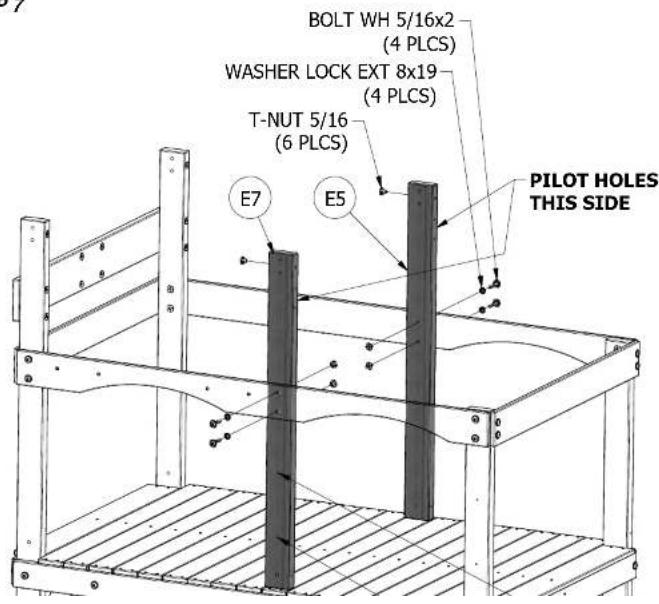
(1) E7-CLUB HOUSE LEG-W4L04826 13/8"x3 3/8"x42 1/2" (36x86x1078)

(1) E5 - CLUB HOUSE LEG - W101490 1 3/8"x3 3/8"x42 1/2" (36x86x1078)
FORT ASSEMBLY
STEP 7
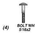



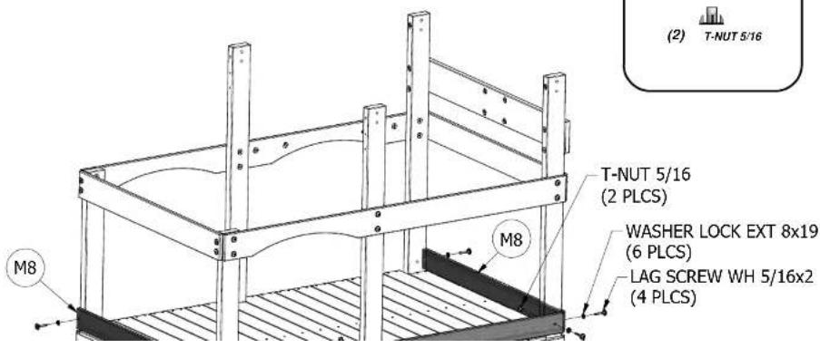
(2) MB - WALL RAIL - W101454 5/8"x3 3/8"x40 3/8" (16x86x1024)

(1) M10 - WALL HAIL - W101494 5/8"x3 3/8"x37 1/2" (16x86x951)
FORT ASSEMBLY
STEP 8
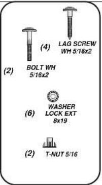

(2) ES - L BRACKET GREEN 32x51 - A100061
FORT ASSEMBLY
STEP 9
PLACE L BRACKETS APPROX AS SHOWN AND ORIENTED LIKE THE DETAIL BELOW. DRILL THROUGH 'M13' BOARDS WITH A 7/16" DIA BIT.

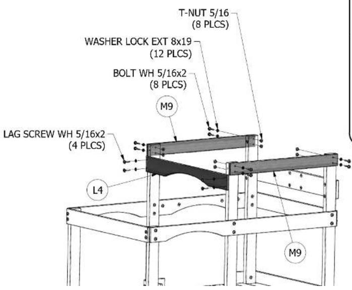
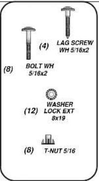
(2) M9 - WALL RAIL - W101496 5/8"x3 3/8"x37 1/2" (16x86x951)

(1) L4 - CLUB HOUSE WALL RAIL - W101491 5/8"x4 3/8"x40 3/8" (16x112x1024)
FORT ASSEMBLY
STEP 10
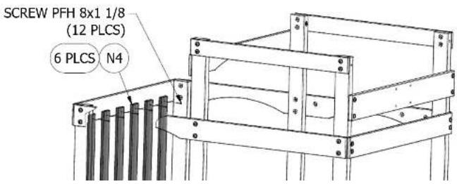
(6) N4 - PICKET - W101492
5/8"x2 3/8"x21 3/8" (16x60x542)
FORT ASSEMBLY
STEP 11
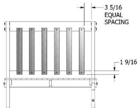
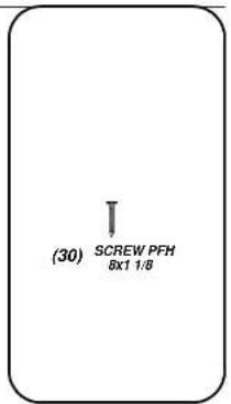
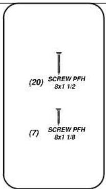
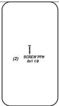
(12) SCREW PFH 8x1 1/8
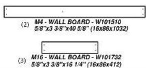
(8) M15 - WALL BOARD - W101506 5/8"x3 3/8"x3 1/2" (16x86x88)
FORT ASSEMBLY
STEP 12
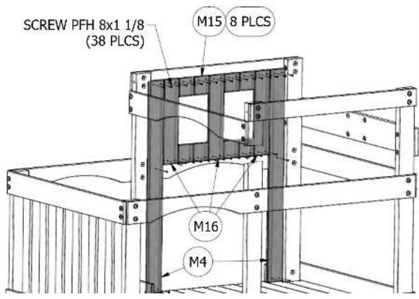
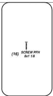
(38) SCREW PFH 8x1 1/8
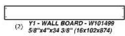
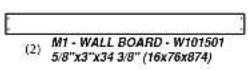
FORT ASSEMBLY
STEP 13
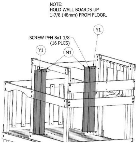

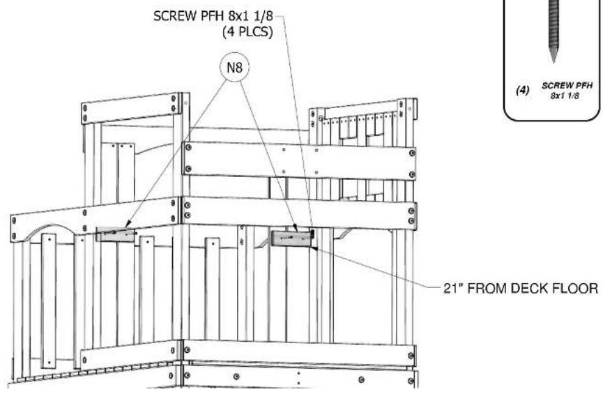
(2) N8 - WALL BOARD SUPPORT - W100595 5/8"x2 3/8"x6 3/4" (16x60x170)
FORT ASSEMBLY
STEP 14

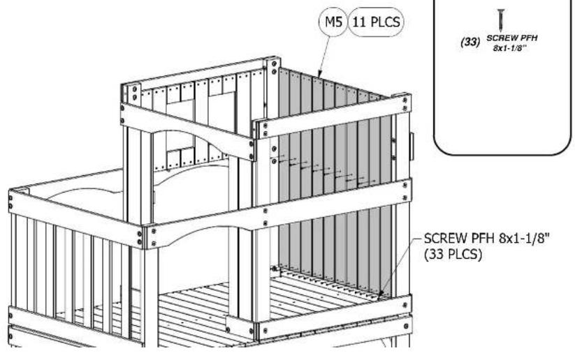
(11) M5 - WALL BOARD - W101497 5/8"x3 3/8"x38 7/8" (16x86x986)
FORT ASSEMBLY
STEP 15
NOTE:
HOLD M5 WALL BOARDS UP
1-7/8 (48mm) FROM FLOOR.
(9) M17 - WALL BOARD - W101493 5/8"x3 3/8"x21 3/8" (16x86x542)
FORT ASSEMBLY
STEP 16
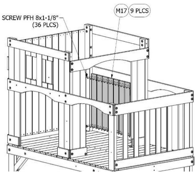
NOTE: HOLD M17 WALL BOARDS UP 1-7/8 (48mm) FROM FLOOR.
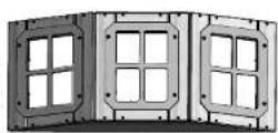
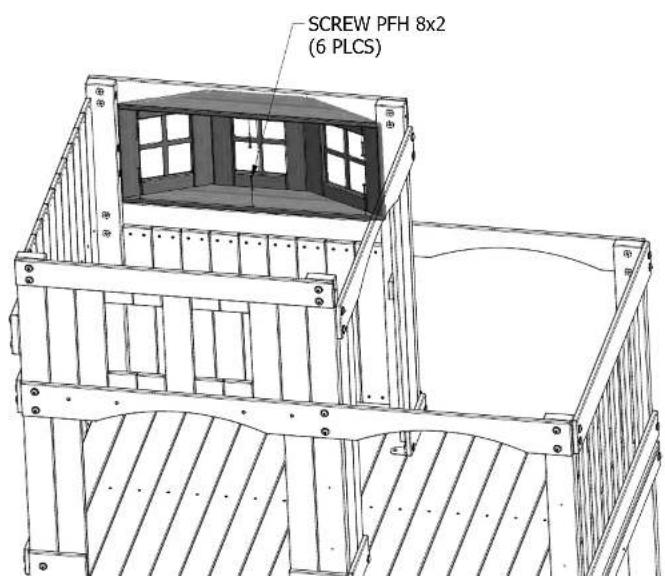
(1) BAY WINDOW ASSEMBLY
FORT ASSEMBLY
STEP 17
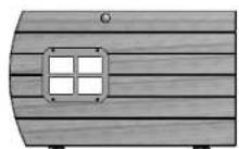
(1) DOOR ASSEMBLY
FORT ASSEMBLY STEP 18
CENTER DOOR IN OPENING, LEFT TO RIGHT AND TOP TO BOTTOM.
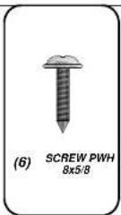
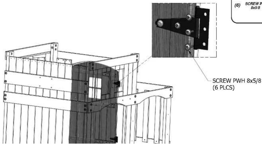
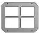
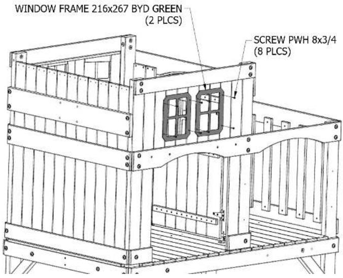
(2) GK-WINDOW FRAME 216x267 BYD GREEN-A100146
FORT ASSEMBLY
STEP 19
FORT ASSEMBLY STEP 20
(4)
(4)

(4)


(2) MB·WALL RAIL·W101454 5/8"x3 3/8"x40 3/8" (16x86x1
FORT ASSEMBLY
STEP 21
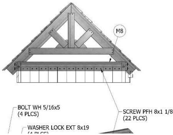
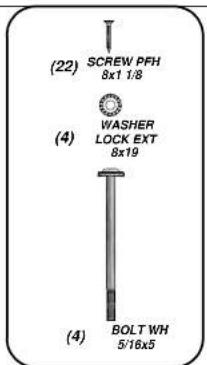
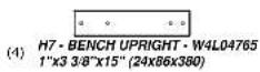
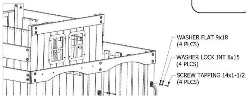
FORT ASSEMBLY STEP 22
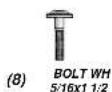

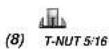
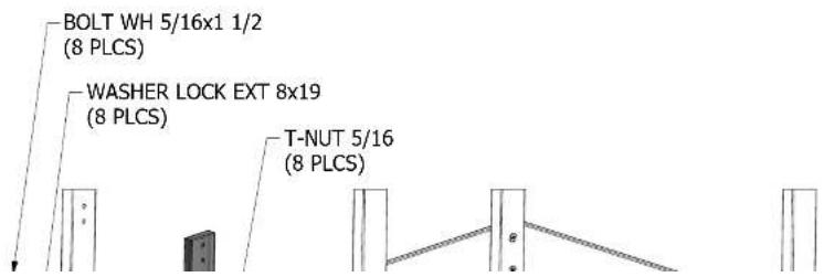
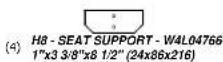
FORT ASSEMBLY STEP 23
(8)
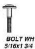
(8)

(8)

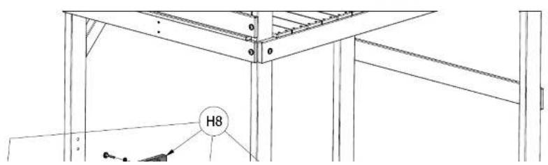
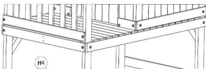
(2) H4 - TABLE SUPPORT - W4L04818 1"x3 3/8"x16 3/4" (24x86x424)
FORT ASSEMBLY STEP 24
(4)

BOLT WH 5:16x2 1/4

WASHER
LUCK E Sv19

T-NUT 5/16 (4)
natural_image
Technical line drawing of a structural frame with supports and beams (no text or symbols)
(4) M2·TABLE BOARD·W4L04820
5/8"x3 3/8"x40 3/8" (16x86x1024)

(1) M7 - TABLE CENTER BOARD - W4L04819
5/8"x3 3/8"x37 1/2" (16x86x952)

(1) N1-5 BOARD CLEAT-W4L04828
5/8"x2 3/8"x15 1/4" (16x60x388)
FORT ASSEMBLY
STEP 25
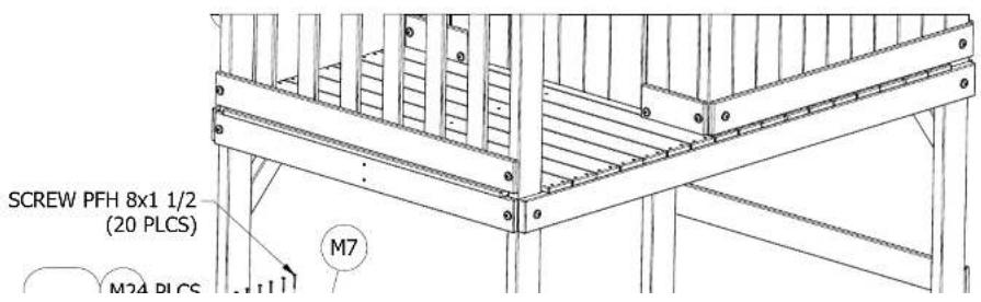

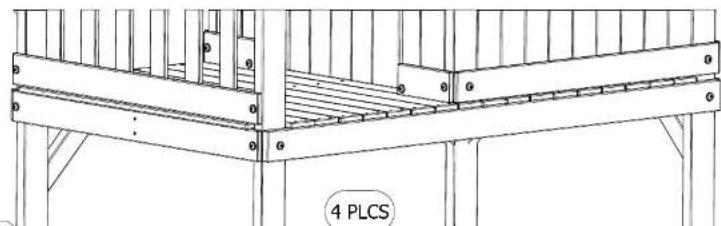
(4) Q1 - BENCH SEAT - W4L04816
1"x4 3/8"x42 1/2" (24x112x1078)
FORT ASSEMBLY STEP 26
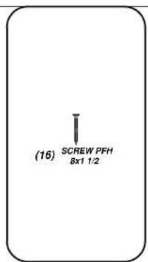
SCREW PFH 8x1 1/2
natural_image
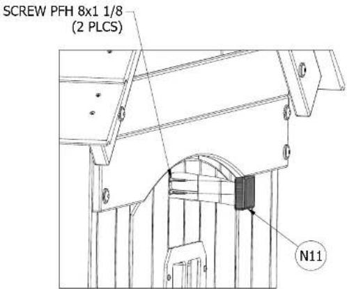
Technical line drawing of a structural frame with supports and columns, labeled '4 PLCS' (no other text or symbols)(1) N11 - DOOR STOP - W101236 5/8"x2 3/8"x2" (16x60x51)
FORT ASSEMBLY STEP 27
DRILL TWO 1/4" DIA HOLES THROUGH 'M1' AS SHOWN BELOW.
LOCATE 'N11' ON THE OUTSIDE OF 'M1' AS SHOWN BELOW.
(4) DG - CHAIN GREEN 38.5" - A100015

(1) DN - GLIDER SEAT DARK GREEN - A100025
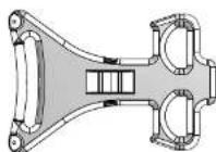
(2) DJ - GLIDER ARM LIGHT GREEN - A100021

(4) FA - QUICK LINK - A100069
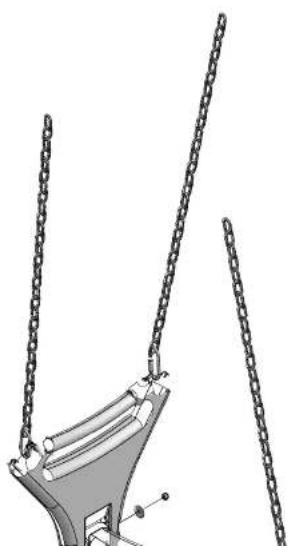
GLIDER ASSEMBLY
natural_image
Mechanical component diagram showing two vertical chains attached to a curved base (no text or symbols)
CHAIN GREEN 38.5" (4 PLCS)
QUICK LINK
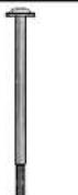
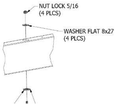
(2) BOLT WH 5/16×5 3/4

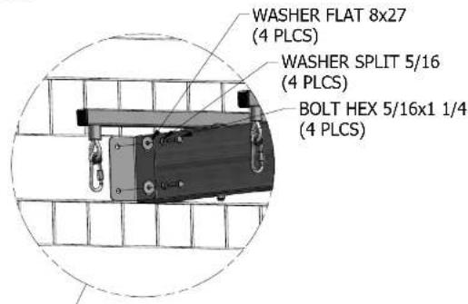
(4) WASHER FLAT 8x27

(2) NUT LOCK 5/16
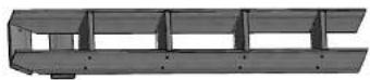
(1) LADDER ASSEMBLY
FINAL ASSEMBLY
STEP 1
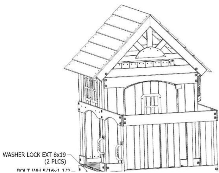
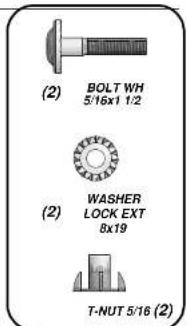
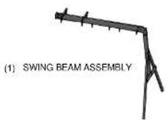
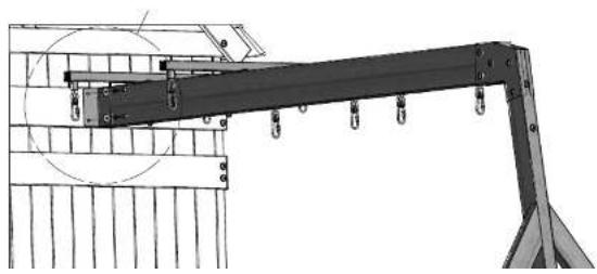
FINAL ASSEMBLY STEP 2
natural_image
Technical line drawing of a mechanical crane with hanging weights and structural supports (no text or symbols)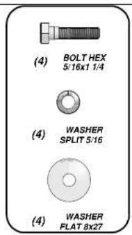
(1) MONKEY BAR ASSEMBLY
FINAL ASSEMBLY
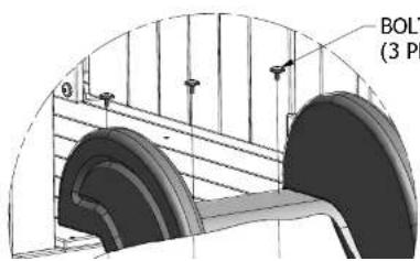
STEP 3
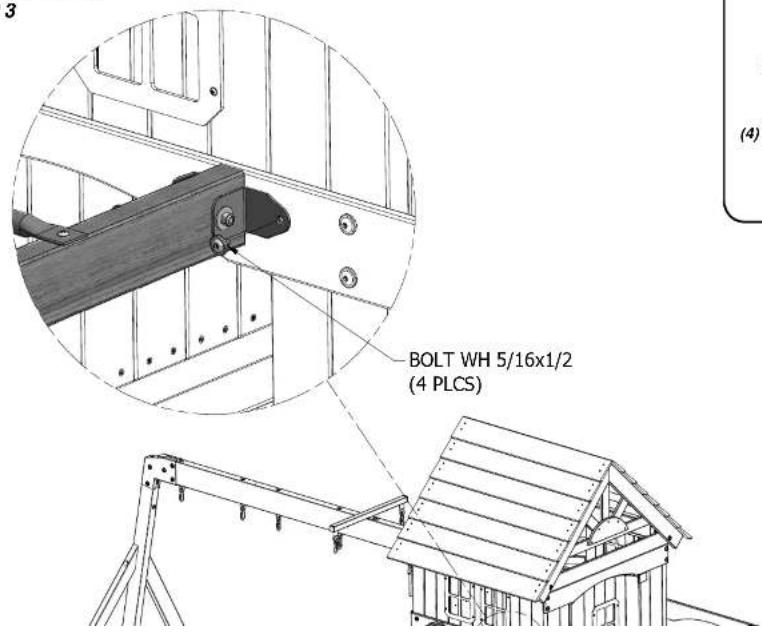

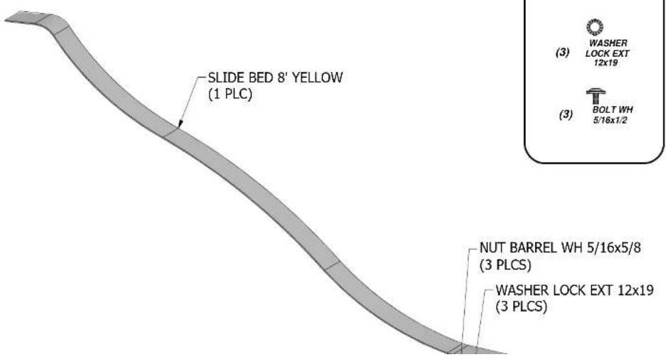
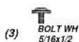
(4) BOLT WH 5/16x1/2
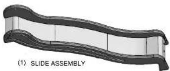
natural_image
3D rendering of a slide assembly with curved bands (no text or symbols)FINAL ASSEMBLY
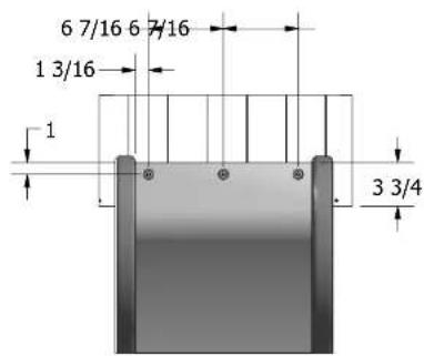
STEP 4
DRILL 7/16" DIA HOLES
THROUGH SLIDE BED AND
DECK BOARDS AT LOCATIONS
SHOWN.
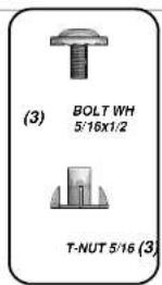
natural_image
Technical diagram of a mechanical assembly with two circular components and mounting brackets (no text or symbols)BOLT WH 5/16x1/2 (3 PLCS)
natural_image
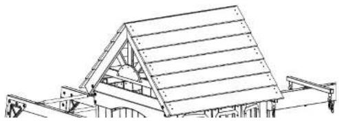
Technical line drawing of a structural frame with diagonal beams and supports (no text or symbols)
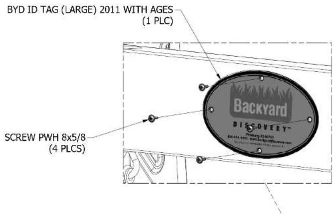
(1) HC - BYD ID TAG (LARGE) 2011 WITH AGES - A100164
FINAL ASSEMBLY STEP 5
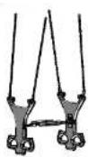
(1) GLIDER ASSEMBLY
FINAL ASSEMBLY STEP 6
natural_image
Technical line drawing of a structural frame with hanging weights and chains (no text or symbols)
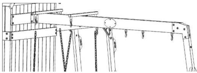
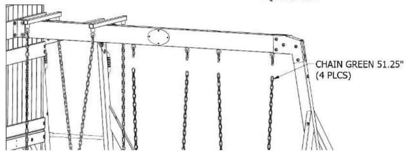
(2) FB-SWING SEAT YELLOW-A100070

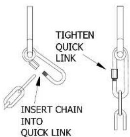
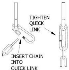
(4) FA - QUICK LINK - A100069

(4) EZ-CHAIN GREEN 51.25"-A100068
FINAL ASSEMBLY STEP 7

FINAL ASSEMBLY STEP 8
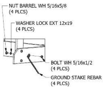
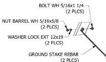
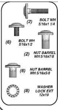
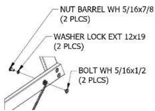
TAP IN GROUND STAKES AT AN APPROXIMATE 45° ANGLE AT THE LOCATIONS SHOWN. USING GROUND STAKES AS A GUIDE, DRILL 7/16" DIA HOLES.
NOTE: FAILURE TO USE GROUND STAKES CAN VOID WARRANTY & CAUSE INJURY!
STAKE FIGURE 1
(4 PLCS)
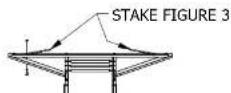
STAKE FIGURE 2 (2 PLCS)
Limited Warranty
This Limited Warranty by Backyard Discovery applies to products manufactured under the Backyard Discovery brand or its other brands including but not limited to Backyard Botanical, Adventure Playsets, and Leisure Time Products.
Backyard Discovery warrants that this product is free from defect in materials and workmanship for a period of one (1) year from the original date of purchase. This one (1) year warranty covers all parts including wood, hardware, and accessories. All wood carries a five (5) year pro-rated warranty against rot and decay. Refer to the schedule below for charges associated with replacement of parts under this Limited Warranty. In addition, Backyard Discovery will replace any parts within the first 30 days from date of purchase found to be missing from or damaged in the original packaging.
This warranty applies to the original owner and registrant and is non-transferable. Regular maintenance is required to assure maximum life and performance of this product and failure by the owner to maintain the product according to the maintenance requirements may void this warranty. Maintenance guidelines are provided in the Owner's Manual.
This Limited Warranty does not cover:
• Labor for any inspection
• Labor for replacement of any defective item(s)
- Incidental or consequential damages
• Cosmetic defects which do not affect performance or integrity of a part or the entire product
- Vandalism, improper use, failure due to loading or use beyond the capacities stated in the applicable Assembly Manual.
- Acts of nature including but not limited to wind, storms, hail, floods, excessive water exposure
- Improper installation including but not limited to installation on uneven, unlevel, or soft ground
- Minor twisting, warping, checking, or any other natural occurring properties of wood that do not affect performance or integrity
Backyard Discovery products have been designed for safety and quality. Any modifications made to the original product could damage the structural integrity of the unit leading to failure and possible injury. Modification voids any and all warranties and Backyard Discovery assumes no liability for any modified products or consequences resulting from failure of a modified product.
This product is warranted for RESIDENTIAL USE ONLY. Under no circumstance should a Backyard Discovery product be used in public settings. Such use may lead to product failure and potential injury. Any and all public
- INSTALLATION
- SERVICES
- STOP
- PARE
- Owner's Manual Play Set
- Dear Customer:
- For Your Records:
- Positioning Your Playcenter
- Suggested Playground Surfacing
- The following chart explains the fall height in feet from which a life threatening head injury would not be expected
- Critical Heights in feet (m) of Tested Materials
- Operating Instructions:
- Maintenance Instructions:
- At the beginning of each play season:
- Twice a month during play season:
- Additional Maintenance:
- Disposal Instructions:
- Third Party Assembly:
- APPENDIX A
- Information on Playground Surfacing Materials:
- Play Set Assembly Manual FAQs:
- Tools Required for Installation:
- Basic Setup Dimensions
- General Information:
- Parts Identification
- Wood Components
- (NOT TO SCALE)
- Wood Components (NOT TO SCALE)
- Hardware
- FORT ASSEMBLY
- STEP 9
- FORT ASSEMBLY STEP 27
- FINAL ASSEMBLY STEP 8
- Limited Warranty
Brand : Backyard Discovery
Model : Springboro
Category : Uncategorized