ROU-5000 - Milling machine Ozito - Free user manual and instructions
Find the device manual for free ROU-5000 Ozito in PDF.


| Product Type | Router (Milling Machine) |
| Brand | Ozito |
| Model | ROU-5000 |
| Power Input | 850 W |
| Voltage | 230-240 V ~ 50 Hz |
| No Load Speed | 11,500 - 32,000 /min (variable) |
| Collet Size | 6.35 mm (1/4") |
| Plunge Depth | 30 mm |
| Turret Depth Stop | 3-step adjustable |
| Weight | 3.3 kg |
| Dust Extraction | Yes (adaptor included) |
| Guide Fence | Included |
| Template Guide | Included |
| Variable Speed Control | Dial on top of motor housing |
| Plunge Lock | Lever on side |
| Spindle Lock | Button near collet |
| Lock-On Switch | Slide switch for continuous operation |
| Double Insulated | Yes (no earth wire required) |
| Carbon Brushes | Replaceable (set SPROU5000-15) |
| Maintenance | Keep vents clean; use moist cloth; replace brushes when worn |
| Safety Features | Double insulation, lock-on switch, spindle lock |
| Warranty | 3-year replacement warranty |
| Spare Parts Available | Collet nut (SPROU5000-59), collet (SPROU5000-58), spring (SPROU5000-57), carbon brushes (SPROU5000-15) |
| Application | Routing, grooving, chamfering, edge profiling, inlay work |
Frequently Asked Questions - ROU-5000 Ozito
User questions about ROU-5000 Ozito
0 question about this device. Answer the ones you know or ask your own.
Ask a new question about this device
Download the instructions for your Milling machine in PDF format for free! Find your manual ROU-5000 - Ozito and take your electronic device back in hand. On this page are published all the documents necessary for the use of your device. ROU-5000 by Ozito.
USER MANUAL ROU-5000 Ozito
Below is a list of common router bits and their uses.
STRAIGHT BITS
Straight router bits a ideal for making plunge cuts into a material to form a groove or to hollow out an area for a mortise or inlay.

COVE BIT
Used to create a concave, rounded edge to a piece of timber. Often used in conjunction with a round over bit.

natural_image
Simple line drawing of a bottle and a yellow abstract shape (no text or symbols)V GROOVE BITS
Used to create V shaped channels or flutes in a workpiece.

natural_image
Simple line drawing of a bottle and a geometric shape (no text or symbols)ROUND OVER BIT
Creates a rounded edge on a piece.

natural_image
Simple line drawing of a mechanical component with a flanged base and a curved side (no text or symbols)ROUND NOSE BITS
Similar to the V-groove bit in that it creates channels or flutes in a

CHAMFER
Cuts a 45-degree angle on a square edge.

MAINTENANCE
- Keep the ventilation vents of the router clean at all times, if possible, prevent foreign matter from entering the vents.
- After each use, blow air through the router housing to ensure it is free from all dust particles which may build up. Build up of dust particles may cause the router to overheat and fail
- If the enclosure of the router requires cleaning, do not use solvents but a moist soft cloth only. Never let any liquid get inside the router; never immense any part of the router into a liquid.
Carbon Brushes
When the carbon brushes wear out, the router will spark and/or stop. Discontinue use as soon as this happens. They should be replaced prior to recommending use of the router. Carbon brushes are a wearing component of the router therefore not covered under warranty. Continuing to use the router when carbon brushes need to be replaced may cause permanent damage to
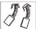
brushes need to be replaced, take the router to an electrician or a power tool repairer for a quick and low cost replacement. Always replace both carbon brushes at the same time. Note: Ozila Industries will not be responsible for any damage of injuries caused by the repair of the router by an unauthorised person or by mishandling of the router.
TROUBLESHOOTING
| SYMPTOM | POSSIBLE CAUSE | REMEDY |
| Router will not operate | No supply of power | Check that power is available at source |
| Router runs slowly | Blunt or damaged router bits | Re-sharpen or replace router bits |
| Variable speed set low | Increase variable speed setting | |
| Motor is overloaded | Reduce excessive load or force on router | |
| Excessive vibration | Bent router bit shaft Replace router bit | |
| Sparking visible through the housing vents | This is normal and does not indicate a problem | No action is required |
| Heavy sparking occurs inside motor housing | Brushes not moving freely | Disconnect power, remove brushes, clean or replace |
DESCRIPTION OF SYMBOLS
| V | Volts | Hz | Hertz |
| - | Alternating current | W | Watts |
| /min | Revolutions or reciprocation per minute | No | No load speed |
| Read instruction manual | [2657] | Warning | |
| Double insulated | [3748] | Regulator compliance mark |
SPARE PARTS
Collet Nut SPROU5000-59
6.35mm Collet SPROU5000-58
Collet Spring SPROU5000-57
Carbon Brushes (set) SPROU5000-15
Spare parts can be ordered from the Special Orders Desk at your local Bunnings Warehouse.
For further information, or any parts not listed here, visit www.ozito.com.au or contact Ozito Customer Service:
Australia 1800 069 486
ELECTRICAL SAFETY

WARNING! When using mains-powered tools, basic safety precautions, including the following, should always be followed to reduce risk of fire, electric shock, personal injury and material damage.
Read the whole manual carefully and make sure you know how to switch the tool off in an emergency, before operating the tool.
Save these instructions and other encaments applied with this tool for future references
The electric motor has been designed for 230V and 240V only. Always check that the power supply
corresponds to the village on the rating plate.
Note: The supply of 230V and 240V on Ctto feels are interchangeable for Australia and New Zealand.

This tool is double insulated; therefore no earth wire is required.
If the supply cord is damaged, it must be replaced by an electrician or a power tool repairer in order to avoid a barrier.
Note: Double insulation does not take the phase of normal safety precautions when operating this xo. The insulation system is for added protection against injury resulting from a positive electrical insulation failure within the test.
Using an Extension Lead
Always use an approved extension load suitable for the power input of this tool. Before use, inspect the extension load for signs of carriage wear and opening. Suppose the extension was if the target or defective. When using an extension load on a seat, always unlike the load completely. Use of an extension load not suitable for the power input of the slot in which so damaged or defective may result in a risk of the seat electric shock.
GENERAL POWER TOOL SAFETY WARNINGS

WARNING! Read all safety warnings and all instructions. Failure to follow the warnings and
A instructions may result in electric shock, fire shock for seismic injury
Save all warnings and instructions for future reference. The term "power tool" in the
warnings refers to your mains-operated (corded) power tool or battery-operated (cordless) power
too!
-
Work area safety
-
Keep work area clean and well ill. Cluttered of 50K shots P/700 Solutions.
b. Do not operate power tools in explosive atmospheres, such as in the presence of flammable
liquids, gases or dust. Power tools create sparks which may ignite the dust or fumes.
c. Keep children and bystanders away while operating a power tool. Distraction can cause you to
losa control
- Electrical safety
a. Power tool plugs must match the outlet. Never modify the plug in any way. Do not use any
adapter plugs with earthed (grounded) power tools. Unmodified plugs and matching outlets will
reduce risk of electric shock
b. Avoid body contact with earthed or grounded surfaces, such as pipes, radiators, ranges and
refrigerators. There is an increased risk of electric shock if your body is washed or grounded.
c. Do not expose power tools to rain or wet conditions. (See exercise: a power tool and increase the
risk of electric shock.
d. Do not share the cord. Never use the cord for carrying, pulling or unplugging the power tool.
Keep cord away from heat, all, sharp edges or moving parts. Damaged or enlarged cards increase
the risk of electric shock
c. When operating a power tool outdoors, use an extension cord suitable for outdoor use. Use of a
-
Which operating a power tool outdoors, use an electric cord suitable for outdoor user cord suitable for outdoor use reduces the risk of electric shoes.
-
If operating a power tool in a damp location is unavoidable, use a residual current device (RCD)
protected sup
- Personal safety
a. Stay alert, watch what you are doing and use common sense when operating a power tool. Do
not uses a power tool while you are tired or under the influence of drugs, alcohol or medication. A
moment, of instance, with operating power scale - by result in census personal injury.
b. Use personal protective equipment. Always wear eye protection. Protection equipment such as dust
mask, non-said safety shoes, hard hat, or hearing protection used for appropriate conditions will reduce
perso#n##s.
c. Prevent unintentional starting. Ensure the switch is in the off-position before connecting to
power source and/or battery pack, picking up or carrying the tool. Carrying power tools with your
finger on the switch or energizing power lock that have the switch on in-mates students.
- Remove any adjusting key or wrench before turning the power tool on. A wrench or a key left
attached to a rotating part of the power tool may result in persons' injury.
Do not overreach. Keep proper fooling and balance at all times. The strategies better control of the
power tool in unexpected situations
Dress properly. Do not wear loose clothing or jewellery. Keep your hair, clothing and gloves away
from moving parts. Loose clothes, jewelry or long hair can be caught in moving parts.
c. If devices are provided for the connection of dust extraction and collection facilities, ensure
these are connected and properly used. Use of dust collection can reduce dust-related hazards.
-
Power tool use and care
-
Do not force the power tool. Use the correct power tool for your application. The correct power tool
will do the job better and safer at the rate for which it was designed
b. Do not use the power tool if the switch does not turn it on and off. Any power tool that cannot be
controlled with the switch is dangerous and must be repaired.
c. Disconnect the plug from the power source and the battery pack from the power load before
- Discrete to the plug from the power source and of the utility path from the power tool offered, making any adjustments, changing accessories, or storing power tools. Such prospective safety
measures not be the risk of storing the power to incidently
c. Store idle power tools out of the reach of children and do not allow persons unfamiliar with the
power tool or these instructions to operate the power tool. Power tools are dangerous in the hands
of untrained users.
- Maintain power tools. Check for misalignment or binding of moving parts, breakage of parts and
any other condition that may affect the power tool's operation. If damaged, have the power tool
repaired before use. Many products are caused by poorly maintained power tools.
- Keep cutting tools sham and clean. Provedly maintained cuttle tacks with soap, cutting edges are
less likely to be a real, and we prefer in control.
- Use the power tool, accessor, and heel bits etc. In accordance with these instructions, value
Use the power tube, accessories and tool bits etc. In accordance with these instructions, taking into account the working conditions and the work in be performed. Use of the wear tool for
operations different from these infected could result in a severity situation.
5 Service
-
Have your power tool serviced by a qualified repair person using only identical replacement
-
Have your power tool serviced by a qualified repair person using only technical replacement parts. This will ensure that the safety of the power box is maintained.

ROUTER
850W
INSTRUCTION MANUAL
SPECIFICATIONS
Voltage: 230-240V - 50Hz
Input: 850W
No Load Speed: 11,500-32,000/min
Collet Size: 6.35mm (1/4")
Plunge Depth: 30mm
Turret Stops:
3.3kg
ozito.com.au

natural_image
Line drawing of a mechanical presser with 'ozito' branding and mounting base (no text or symbols on the device itself)WHAT'S IN THE BOX
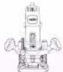
Router
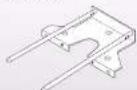
Guide Fence

Dust Extraction Adaptor

Template Guide
3 YEAR REPLACEMENT WARRANTY
ROU-5000
WARRANTY
IN ORDER TO MAKE A CLAIM UNDER THIS
WARRANTY YOU MUST RETURN THE PRODUCT
TO YOUR NEAREST BUNNINGS WAREHOUSE WITH
The benefits provided under this warranty are in addition
to other rights and remedies which are available to you at law.
Our goods come with guarantees that cannot be excluded
at least V_0 was notified to a replacement or refund for a claim.
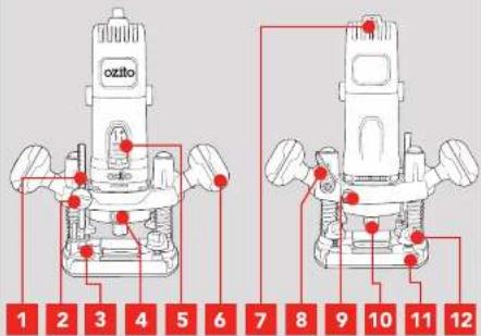
KNOW YOUR PRODUCT
ROUTER
1 Depth Rod
2 Depth Rod Adjustment Knob
3 Turret Depth Stop
4 Spindle Lock Button
5 Lock On Slide Switch
6 Handles
7 Variable Speed Dial
8. Plunge Lock Lever
9 Router Fixing Nut
10 Collet Nut
11 Base
12 Fence Locking Knob
ACCESSORIES
13 Spanner
14 Dust Extraction Adaptor
15 Template Guide
16 Hex Key
18 Guide Fence Rod Screws
19 Dust Extraction Adaptor Screws
20 Guide Fence
21 Guide Fence Rods
SETUP & PREPARATION
1. ASSEMBLY
Side Handles
- Put together the side handle assembly: screw, spring washer, washer, side handle.
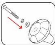
- Align the handles to the fixing square on sides of router.
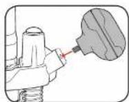
- Fasten into place by tightening screw with a no 2 Phillips head screwdriver.
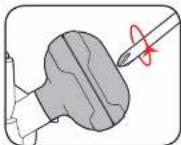
- Insert cover buttons to cover the screws.
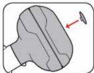
Fitting Router Bits

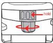
CAUTION: ENSURE THE SPINDLE STOPS COMPLETELY BEFORE LOCKING.
2. DUST EXTRACTION ADAPTOR 3. GUI
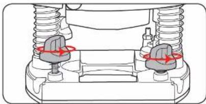
The dust extraction adaptor allows you to connect a vacuum cleaner or dust extractor to the router.
- Depress spindle lock button and loosen collet nut. Remove the collet nut and collet completely.
- Remove the 2 fence locking knobs from the rear of the router.
natural_image
Mechanical assembly diagram showing two springs and a housing with red directional arrows indicating motion (no text or symbols)- Ensure you are inserting the adaptor from the rear of the router. Align the front of the adaptor with the recess in the base. Tilt the front lip of the adaptor down to clear the spindle and insert into place.

FENCE & TEMPLATE GUIDE
The guide fence is an effective aid when cutting in a straight line when chamfering or grooving.
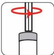
- Loosen screws on the end of guide rods with hex key.
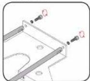
- Line the guide rods up with the holes in the guide fence. Secure in place with the fence screws.
- Loosen guide fence locking knobs.
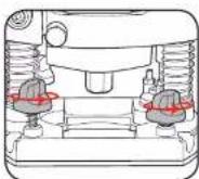
- Feed the guide fence rods through the holes in the router base.
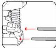
- Adjust the guide fence until it is the correct distance from the router bit and the cut to be made. Tighten guide fence locking looks to fasten guide fence in place.
OPERATION
4. ADJUSTING DEPTH OF CUT 5. ADJUS
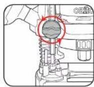
Visually
This method is best suited when routing the outside edge of a workpiece.
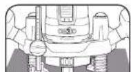
- Set the turret stop to the lowest setting.
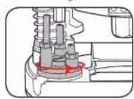
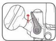
- Ensure the plunge lock lever is released.
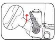
-
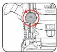
Loosen the depth rod adjustment knob until the depth rod drops down to the turret stop.
-
Place the router on the workpiece so that the router bit over hangs the work edge.
NG DEPTH OF CUT
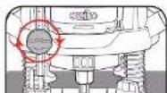
By Measurement
This method is best suited when routing the inside the workpiece.
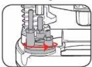
- Set the turret stop to the desired setting.
- Ensure the plunge lock lever is released.
-
Loosen the depth rod adjustment knob until the depth rod drops down to the turret stop.
-
Plunge the router down until the router bit touches the workpiece then tighten the depth rod adjustment knob.
6. CONTROLS
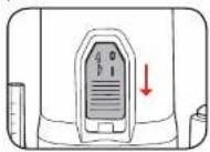
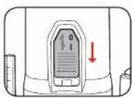
Turning On/Off
To turn on, push the slide on/off switch down toward the "I" position.
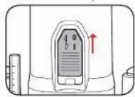
To turn off, press on the rear of the on/off switch so that it slides back to the "0" position.
Variable Speed Control
Scroll through the variable speed dial to select the appropriate speed for the working material.
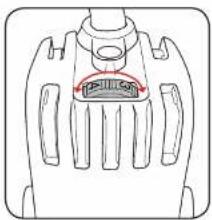
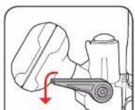
Plunge Lock Lever
7. MAKING A CUT
- Place the base plate on the workpiece, ensuring the bit is not in contact with the material to be cut.
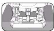
-
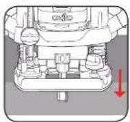
Lower the router body into the work piece.
-
Lock the router in position at the desired cutting depth.
-
Turn the router on and wait for the bit to reach full speed.
- STRAIGHT BITS
- COVE BIT
- V GROOVE BITS
- ROUND OVER BIT
- ROUND NOSE BITS
- CHAMFER
- MAINTENANCE
- Carbon Brushes
- TROUBLESHOOTING
- DESCRIPTION OF SYMBOLS
- SPARE PARTS
- ELECTRICAL SAFETY
- GENERAL POWER TOOL SAFETY WARNINGS
- ROUTER
- 850W
- INSTRUCTION MANUAL
- SPECIFICATIONS
- ozito.com.au
- WHAT'S IN THE BOX
- YEAR REPLACEMENT WARRANTY
- WARRANTY
- KNOW YOUR PRODUCT
- ACCESSORIES
- SETUP & PREPARATION
- ASSEMBLY
- Side Handles
- DUST EXTRACTION ADAPTOR 3. GUI
- FENCE & TEMPLATE GUIDE
- OPERATION
- ADJUSTING DEPTH OF CUT 5. ADJUS
- Visually
- NG DEPTH OF CUT
- By Measurement
- CONTROLS
- Turning On/Off
- Variable Speed Control
- MAKING A CUT
Brand : Ozito
Model : ROU-5000
Category : Milling machine