
CB95W - Cooker Campomatic - Free user manual and instructions
Find the device manual for free CB95W Campomatic in PDF.


| Product Type | Freestanding Cooker |
| Brand | Campomatic |
| Model | CB95W |
| Width | 60 cm |
| Depth | 60 cm |
| Height | 85 cm |
| Weight | Approx. 50 kg |
| Power Supply | 220-240 V, 50/60 Hz, 16 A |
| Number of Gas Burners | 4 |
| Burner Types | Standard, Rapid, Auxiliary (varying sizes) |
| Oven Type | Electric Fan Oven |
| Oven Capacity | 70 L |
| Oven Functions | Bake, Grill, Fan, Defrost |
| Grill | Built-in, full width |
| Control Type | Knobs and push buttons |
| Timer | Digital, with alarm |
| Interior Light | Yes, in oven |
| Cleaning | Easy-clean enamel interior, removable door |
| Safety Features | Flame failure device on gas burners, child lock, auto shut-off |
| Energy Class | A |
Frequently Asked Questions - CB95W Campomatic
User questions about CB95W Campomatic
0 question about this device. Answer the ones you know or ask your own.
Ask a new question about this device
Download the instructions for your Cooker in PDF format for free! Find your manual CB95W - Campomatic and take your electronic device back in hand. On this page are published all the documents necessary for the use of your device. CB95W by Campomatic.
USER MANUAL CB95W Campomatic
natural_image
Line drawing of a standard electric stove with top and front panels, no text or symbols presentContents
1.INSTRUCTIONS FOR USE 2-3
2.INSTRUCTIONS FOR DISPOSAL OUR ENVIRONMENTAL CARE....4
3.INSTALLING THE APPLIANCE....5
3.1 Electrical connection....6
3.2 Room ventilation 6
3.3 Extraction of the products of combustion 6
3.4 Connection to gas 7
- ADAPTATION TO DIFFERENT TYPES OF GAS 8
4.1 Replacement of nozzles on the cooking hob 8
4.2 burner and nozzle characteristics table(60CM.model) 9-10
4.3 burner and nozzle characteristics table(90CM.model) 9-10
4.4 Arrangement of the burners on the cooking hob( 60CM.model) 11
4.5 Arrangement of the burners on the cooking hob( 90CM.model) 11
- FINAL OPERATIONS ....12
5.1 Regulation of the hob burners minimum for natural gas 12
5.2 Regulation of the hob burners minimum for Liquid gas 12
5.3 Positioning and levelling the appliance (depending on the model) .....12
5.4 Adjustment of the oven burner minimum 12
-
CONTROL PANEL 13-14
-
USING THE COOKING HOB 15
7.1 Lighting the hob burners .....15
7.2 Practical hints for using the hob burners 15
7.3 60 cm and 90cm cooker pan diameters 16
- USING THE OVEN 17
8.1 Warnings and general advice 17
8.2 Using the gas oven....17
8.3 Using the electric grill 18
8.4 Storage compartment (only on some models) 18
-
AVAILABLE ACCESSORIES 19
-
CLEANING AND MAINTENANCE ....20
10.1 Ordinary daily cleaning ....20
10.2 Cleaning the parts of the cooking hob 20-21
10.3 Cleaning the oven 21
10.4 Cleaning the door glazing 21
- EXTRAORDINARY MAINTENANCE ......22
11.1 Lubrication of gas oven taps and thermostat 22
11.2 Changing the light bulb 22
11.3 Removing the doors .....22
11.4 Removing the doors seal 22
INSTRUCTIONS FOR THE USER: these contain user advice, description of the commands and the correct procedures for cleaning and maintenance of the appliance.

INSTRUCTIONS FOR THE INSTALLER: these are intended for the qualified technician who must carry out an adequate inspection of the gas system, install the appliance, set it functioning and carry out an inspection test.
1. INSTRUCTIONS FOR USE
THIS MANUAL IS AN INTEGRAL PART OF THE APPLIANCE AND THEREFORE IT MUST BE KEPT IN ITS ENTIRETY AND IN AN ACCESSIBLE PLACE FOR THE WHOLE WORKING LIFE OF THE HOB. WE ADVISE READING CAREFULLY THIS MANUAL AND ALL THE INSTRUCTIONS THEREIN BEFORE USING THE HOB. INSTALLATION MUST BE CARRIED OUT BY QUALIFIED PERSONNEL IN ACCORDANCE WITH THE REGULATIONS IN FORCE. THIS APPLIANCE IS INTENDED FOR DOMESTIC USES AND CONFORMS TO THE EEC DIRECTIVES CURRENTLY IN FORCE. THE APPLIANCE HAS BEEN BUILT TO CARRY OUT THE FOLLOWING FUNCTIONS: COOKING AND HEATING-UP OF FOOD; ALL OTHER USES ARE CONSIDERED IMPROPER.
THE MANUFACTURER DECLINES ALL RESPONSIBILITY FOR IMPROPER USE.
DO NOT DISCARD PACKING IN THE HOME ENVIRONMENT. SEPARATE THE VARIOUS WASTE MATERIALS AND TAKE THEM TO THE NEAREST SELECTIVE WASTE COLLECTION CENTRE.

IT IS OBLIGATORY FOR ALL ELECTRICAL SYSTEMS TO BE GROUNDED ACCORDING TO THE METHODS REQUIRED BY SAFETY RULES.

THE PLUG TO BE CONNECTED TO THE POWER SUPPLY CABLE AND ITS SOCKET MUST BE OF THE SAME TYPE AND CONFORM TO THE REGULATIONS IN FORCE. THE SOCKET MUST BE ACCESSIBLE AFTER THE APPLIANCE IS BUILT IN. NEVER DISCONNECT THE PLUG BY PULLING ON THE CABLE.

IF THE POWER SUPPLY CABLE IS DAMAGED, CONTACT THE TECHNICAL SUPPORT SERVICE IMMEDIATELY TO REPLACE IT.

IMMEDIATELY AFTER INSTALLATION, CARRY OUT A QUICK TEST ON THE APPLIANCE FOLLOWING THE INSTRUCTIONS PROVIDED LATER IN THIS MANUAL. SHOULD THE APPLIANCE NOT FUNCTION, DISCONNECT IT FROM THE POWER SUPPLY AND CALL THE NEAREST TECHNICAL ASSISTANCE CENTRE. NEVER ATTEMPT TO REPAIR THE APPLIANCE.
ALWAYS CHECK THAT THE CONTROL KNOBS ARE IN THE (OFF) POSITION WHEN YOU FINISH USING THE APPLIANCE.

NEVER PLACE FLAMMABLE OBJECTS IN THE OVEN: IF IT SHOULD ACCIDENTALLY BE SWITCHED ON, THIS MIGHT CAUSE A FIRE.

THE IDENTIFICATION PLATE WITH THE TECHNICAL DATA, SERIAL NUMBER AND MARK IS IN A VISIBLE POSITION INSIDE THE STORAGE COMPARTMENT. THE PLATE MUST NOT BE REMOVED.
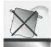
NEVER PLACE PANS WITH BOTTOMS WHICH ARE NOT PERFECTLY FLAT AND SMOOTH ON THE COOKING HOB PAN STANDS.

NEVER USE PANS OR GRIDDLE PLATES WHICH PROJECT BEYOND THE OUTSIDE EDGE OF THE HOB.

HOLD THE GLASS LID WITH YOUR HAND WHILE LOWERING IT.
WARNING: THE GLASS LID CAN SPLINTER IF OVERHEATED.
TURN OFF ALL THE BURNERS AND WAIT FOR THEM TO COOL DOWN BEFORE CLOSING IT.

DURING USE THE APPLIANCE BECOMES VERY HOT. TAKE CARE NOT TO TOUCH THE HEATING ELEMENTS INSIDE THE OVEN.
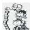
THE APPLIANCE IS INTENDED FOR USE BY ADULTS. DO NOT ALLOW CHILDREN TO GO NEAR IT OR PLAY WITH IT. WHEN THE GRILL IS WORKING THE ACCESSIBLE PARTS CAN BECOME VERY HOT: KEEP CHILDREN AT A SAFE DISTANCE.
Precautions for use

IF THE APPLIANCE IS PLACED ON A PEDESTAL IT MUST BE INSTALLED SO THAT IT CANNOT SLIDE OFF.

IF THE COOKING PRODUCTS ARE INSTALLED ON MOTOR VEHICLES (FOR EXAMPLE, CAMPERS, CARAVANS ETC.) THEY MUST ONLY BE USED WHEN THE VEHICLE IS STOPPED.

INSTALL THE PRODUCT SO THAT WHEN OPENING THE DRAWERS AND DOORS OF UNITS POSITIONED AT THE LEVEL OF THE COOKING HOB THERE IS NO POSSIBILITY OF MAKING CONTACT WITH PANS POSITIONED ON TOP OF IT.

THIS APPLIANCE MAY NOT BE USED BY PEOPLE (INCLUDING CHILDREN) OF REDUCED PHYSICAL AND MENTAL CAPACITY, OR LACKING IN EXPERIENCE IN THE USE OF ELECTRICAL APPLIANCES, UNLESS THEY ARE SUPERVISED OR INSTRUCTED BY ADULTS RESPONSIBLE FOR THEIR SAFETY.

THIS APPLIANCE IS MARKED ACCORDING TO THE EUROPEAN DIRECTIVE 2002/96/EC ON WASTE ELECTRICAL AND ELECTRONIC EQUIPMENT (WEEE). THIS GUIDELINE IS THE FRAME OF A EUROPEAN-WIDE VALIDITY OF RETURN AND RECYCLING ON WASTE ELECTRICAL AND ELECTRONIC EQUIPMENT.

BEFORE THE APPLIANCE IS PUT INTO OPERATION, ALL LABELS AND PROTECTIVE FILMS APPLIED INSIDE OR OUTSIDE MUST BE REMOVED.

The manufacturer declines all responsibility for damage to persons or things caused by the non-observance of the above prescriptions or deriving from tampering with any part of the appliance or by the use of non-original spares.
1) Appliance type:Class 2
2) Warning the user against the use of cooking vessels on the hotplate that overlap its edges.
3)This appliance shall be installed in accordance with the regulations in force and only used in a well ventilated space.Read the instructions before installing or using this appliance.
2. INSTRUCTIONS FOR DISPOSAL OUR ENVIRONMENTAL CARE
Our household appliances are only packaged using non-pollutant, environment-friendly, recyclable materials. Please help by disposing of the packing correctly. Find the addresses of collection, recycling and disposal centres from your retailer or from the competent local organisations.
Never leave all or part of the packaging lying around.
Your old appliance also needs to be disposed of correctly.
Important: deliver the appliance to the local agency authorised for the collection of household appliances no longer in use.
Correct disposal means intelligent recycling of valuable materials. Refrigeration appliances contain gases which may damage the environment; it is therefore important to ensure that the refrigeration circuit pipelines are not damaged until the competent service has accepted delivery of the appliance.
Before disposing of your appliance it is important to remove doors and leave shelves in position as for use, to ensure that children cannot accidentally become trapped inside during play. It is also necessary to cut the interconnecting cable to the power supply network, removing it along with the plug.
DO NOT DISCARD PACKING IN THE HOME ENVIRONMENT. SEPARATE THE VARIOUS WASTE MATERIALS AND TAKE THEM TO THE NEAREST SELECTIVE WASTE COLLECTION CENTRE.

INFORMATION FOR USERS:
Pursuant to Directives 2002/95/EC, 2002/96/EC and 2003/108/EC relating to the reduction of the use of hazardous substances in electrical and electronic appliances, as well as to the disposal of refuse. The crossed out bin symbol on the appliance indicates that the product, at the end of its useful life, must be collected separately from other refuse. Therefore, the user must consign the product that has reached the end of its working life to the appropriate selective collection centres for electrical and electronic refuse, or deliver it back to the retailer when purchasing an equivalent product, on a one for one basis. Adequate selective collection for the subsequent forwarding of the decommissioned product to recycling, treatment and ecologically compatible disposal contributes to avoiding possible negative effects on the environment and on health and promotes the recycling of the materials of which the appliance consists. The illicit disposal of the product by the user results in the application of administrative sanctions.
3. INSTALLING THE APPLIANCE

The appliance must be installed by a qualified technician and according to the regulations in force. Depending on the type of installation, it belongs to class 1 (Fig.A) or to class 2-subclass 1 (Fig.B-C). This appliance may be installed next to a wall which is higher than the appliance, with a minimum distance of 150mm from the side of the appliance, as shown in drawings A and B showing the correct installation conditions. Any wall cupboards or shelves must be at a distance of at least 770 mm above the work surface.

A) Built-in appliance
The cooker is supplied with an anti-tilting chain to prevent the appliance from tilting forward and accidental damage to the gas pipe. Take the expansion with hook and make an adequate hole in the wall behind, at the same height as the chain fixing area. I the plug into the hole and then screw in the hook until it is fixed to the wall. Fix the chain to the hook. Adjust to level o cooker inserting the feet provided.

natural_image
Technical line drawing of a dual-chamber energy storage unit with ventilation slots and a control panel (no text or symbols)
Electric oven can only be installed as free-standing (see fig. B).
Warning:
1) Piror to installation ensure that the local distribution conditions (nature of the gas and gas pressure) and the adjustment of the appliance are compatible;
2) The adjustment conditions for this appliance are stated on data plate;
3) This appliance is not connected to a combustion products evacuation device. It shall be installed and connected in accordance with current installation regulations. Particular attention shall be given to the relevant requirements regarding ventilation.
3.1 Electrical connection
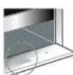
Make sure the voltage and the cross-section of the power supply line match the specifications indicated on the identification plate positioned in the storage compartment.
Do not remove this plate for any reason.

I the appliance is connected to the power supply network by means of a fixed connection, install a multipolar cut-out device on the power supply line, with contact opening distance equal to or greater than

3 mm located near the appliance and in an easily reachable position.
Connection to the power supply network may be fixed or with plug and socket. In the latter case the plug and socket must be suitable for the cable employed and conform with the regulations in force. Regardless of the type of connection, it is compulsory that the appliance be earthed. Before connection make sure that the power supply line is suitably earthed. Avoid use of adapters and shunts.

1 - For operation on 220-240V: use a three-pole cable of the H05RR-F or H05W-F type:
3 × 1.0 mm ^2 (for 90 cm models)
3 × 1.0 mm^2 (for 90 cm models)
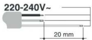

WARNING: THE VALUES INDICATED ABOVE REFER TO THE CROSS-SECTION OF THE INTERNAL CONDUCTOR.

Warning: only some of the 90 cm models can be connected with two or three phases.
3.2 Room ventilation

The room containing the appliance should have an air supply in accordance with the standards in force. The room where the appliance is installed must have enough air flow as required for the regular combustion of gas and by the necessary air exchange of the same room. The air vent, protected by grills, must be suitably dimensioned in compliance with the current regulations and positioned so that no part of it is obstructed.
The cooker must be kept adequately ventilated in order to eliminate the heat and humidity produced by cooking: in particular, after prolonged use, it is recommended to open a window or to increase the speed of any ventilators.
3.3 Extraction of the products of combustion

Extraction of the products of combustion must be ensured by means of hoods connected to a natural draught chimney whose efficiency is assured or via forced extraction. An efficient extraction system requires precision planning by a specialist qualified in this area and must comply with the positions and distances indicated by the regulations. When the job is complete, the installer must issue a certificate of conformity.
3.4 Connection to gas

Installation of the standards-compliant rubber steel hose must be carried out so that the steel hose length is no greater than 1.5 metres. Make sure that the steel hose does not come into contact with moving parts or is squashed.
Gas It's necessity of changing the flexible tube when the national conditions require it.
Verify that all the following conditions are met:
the steel hose is fixed to the steel hose connection with safety clamps;
no part of the steel hose is in contact with the hot walls (max 50 degree C).
the steel hose is not under traction or tension and has no tight curves or twists;
the steel hose is not in contact with sharp objects or sharp corners;
if the steel hose is not perfectly airtight and leaks gas, do not try and repair it: replace it with a new
steel hose verify that the hose is not beyond its life cycle (serigraphed on the hose itself).
THE TIGHTENING TORQUE BETWEEN CONNECTIONS THAT INCORPORATE THE GASKET MUST NOT EXCEED 10NM
3.4.2 Gas connection
Connection with copper pipe:
The connection to the gas supply mains must be made so that no stresses or strains of any kind are applied to the appliance. The connection can be made using the adapter unit D with two conical elements, always fitting the gasket C supplied.
Connection with steel hose:
Use only continuous-wall stainless steel hoses compliant with the relevant regulations, and always fit the gasket C supplied between the fitting A and the hose E.

When connecting with a hose, ensure that the total length of the pipeline is not more than 1.5 metres; also
Ensure that the hoses do not touch moving parts and are not crushed.

The hose connector G illustrated is not supplied with the appliance. Only use standards-compliant hose connectors.
4. ADAPTATION TO DIFFERENT TYPES OF GAS
Before carrying out the following operations, disconnect the appliance from the electricity supply.

The appliance is preset for natural gas G20 (2H) at a pressure of 20 mbar. In the case of operation with other types of gas the burner nozzles must be changed and the minimum flame adjusted on the gas taps. To change the nozzles, proceed as described in the following paragraphs.
4.1 Replacement of nozzles on the cooking hob
1 Extract the pan stands and remove all the caps and flame-spreader crowns;
2 Unscrew the burner nozzles with a 7 mm socket wrench;
3 Replace the burner nozzles according to the type of gas to be used (see paragraph 4.2 Burner and nozzle characteristics table (for 90 cm models)
4 Replace the burners in the correct positions.

natural_image
Technical diagram showing a mechanical assembly with a central component and a magnified inset of the component (no text or symbols present)4.2 Burner and nozzle characteristics table(90 cm.model);
| Burner | By pass mm | Consumption(+) | ||||||||||||
| LPG | Natural gas I 2H | Natural gas I 2L | ||||||||||||
| 15B/P(30) | BB/P(50) | I3-(28-30:37) | ||||||||||||
| C30 | C30 | C30 | G31 | G20 rill gas | G25 rill gas | |||||||||
| Input kw(g/h) | Main Injector mm | Input kw(g/h) | Main Injector mm | Input kw(g/h) | Main Injector mm | Input kw(g/h) | Main Injector mm | Input kw(g/h) | Main Injector mm | Input kw(g/h) | Main Injector mm | |||
| 1 | Rapid | 0.44 | 3.0(218) | 0.85 | 3.0(218) | 0.75 | 3.0(218) | 0.85 | 3.0(214) | 0.85 | 3.0 | 1.15 | 3.0 | 1.21 |
| 2 | Semi-rapid | 0.34 | 1.75(127) | 0.65 | 1.75(127) | 0.58 | 1.75(127) | 0.65 | 1.75(125) | 0.65 | 1.75 | 0.97 | 1.75 | 0.94 |
| 3 | FishBBQ | 0.64 | 2.8(203) | 0.85 | 2.8(203) | 0.70 | 2.8(203) | 0.85 | 2.8(200) | 0.85 | 2.8 | 1.15 | 2.8 | 1.21 |
| 4 | Auxiliary | 0.29 | 1.0(72.7) | 0.50 | 1.0(72.7) | 0.72 | 1.0(72.7) | 0.50 | 1.0(71) | 0.50 | 1.0 | 0.72 | 1.0 | 0.72 |
| 5 | Triple ring | 0.64 | 3.7(269) | 0.95 | 3.7(269) | 0.76 | 3.7(269) | 0.95 | 3.7(264) | 0.95 | 3.7 | 1.46 | 3.7 | 1.42 |
| 6 | Grill gas | 2.8(203) | 0.82 | 2.8(203) | 0.78 | 2.8(203) | 0.82 | 2.8(200) | 0.82 | 2.8 | 1.21 | 2.8 | 1.22 | |
| 7 | Oven gas | 0.45 | 4.5(326) | 1.05 | 4.5(326) | 0.86 | 4.5(326) | 1.05 | 4.5(321) | 1.05 | 4.5 | 1.4 | 4.5 | 1.44 |
| Test point pressure | G30:29mbar | G30:50mbar | G30:29mbar G31:37mbar G3 | G20:20mbar | G25:25mbar | |||||||||
Marking 0.65 on the injector indicates that the size of injector is 0.65mm
With dry gas and with greater calorific power (Hs) at 15 and 1013.26 mbar
| Model | TOTAL HEAT:I NPUT s(H n:(Q) |
| F96A5TMSG2S1 | 15.7kW (1139.6g/h) |
| F96A5TMSG2S1-D | 15.7kW (1139.6g/h) |
| F96A5TLSG2S1 | 15.7kW (1139.6g/h) |
| F96A5TLSG2S1-D | 15.7kW (1139.6g/h) |
| F96A5T2SG2S1 | 16.4kW (1190.4g/h) |
| F96A5T2SG2S1-D | 16.4kW (1190.4g/h) |
| F96A5T3SG2S1 | 19.1kW (1386.4g/h) |
| F96A5T3SG2S1-D | 19.1kW (1386.4g/h) |
| F96A4TSG2S1 | 14.8kW (1074.3g/h) |
| F96A4TSG2S1-D | 14.8kW (1074.3g/h) |
| F96A3TSG2S1 | 13.05kW(947.3g/h) |
| F96A3TSG2S1-D | 13.05kW(947.3g/h) |
| F96A3T2SG2S1 | 15.75kW(1143.2g/h) |
| F96A3T2SG2S1-D | 15.75kW(1143.2g/h) |
| Country of destination | _1a2H | _2H3B/F | _2H3+ | _2L3B/F | |
| Austria | AT | * | |||
| Belgium | BE | ||||
| Denmark | DK | * | * | ||
| Finland | FI | * | |||
| France | FR | ||||
| Germany | DE | ||||
| Greece | GR | * | * | ||
| Iceland | IS | ||||
| Ireland | IE | * | |||
| Italy | IT | * | * | ||
| Luxembourg | LU | ||||
| Netherlands | NL | * | |||
| Norway | NO | ||||
| Portugal | PT | * | |||
| Spain | ES | * | * | ||
| Sweden | SE | * | * | ||
| Switzerland | CH | * | * | * | |
| United Kingdom | GB | * | |||
4.3 Arrangement of the burners on the cooking hob (Mod. 90 cm.)

BURNERS
1.Rapid
2. Semi rapid
3.Auxiliary
4.Triple ring
4.4 Oven burner adjustment (only for models with a gas oven)
To adjust the oven burner you need to open the oven door and carry out the following operations:
Remove the oven basin and its rack.
Lift up the oven surface and pull it outwards.

natural_image
Close-up of a transparent plastic enclosure with internal components and mounting holes (no visible text or symbols)4.4.1 Replacing the oven burner nozzle
Loosen the oven burner fixing screw A.
Push the burner B towards the right until the nozzle is accessible.
Using a 13 socket spanner replace the nozzle, inserting a new nozzle suitable for the type of gas to be used (see paragraph .2/3.3 Burner and nozzle characteristics table).

natural_image
Mechanical component diagram showing a transparent housing with labeled parts A and B (no text or symbols beyond labels)4.4.2 Primary air adjustment for the oven burner
Loosen the adjustment screw A of the air regulation sleeve.
Turn the adjustment sleeve to the position that corresponds to the type of gas to be used according to the table below.
Tighten the adjustment screw and restore the seals.
When the operation is completed, reassemble the burner correctly.

| NATURAL GAS | G 30/31 (LPG) | |
| X= | 5 mm | 10 mm |
5. FINAL OPERATIONS
After replacing the nozzles, reposition the flame-spreader crowns, the burner caps and the pan stands.
Following adjustment to a gas other than the preset one, replace the gas adjustment label fixed to the appliance with the one corresponding to the new gas. The label is inserted inside the pack together with the nozzles.
5.1 Regulation of the hob burners minimum for natural gas
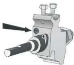
Light the burner and turn it to the minimum position 0. Extract the gas tap knob and turn the adjustment screw at the side of the tap rod until the correct minimum flame is achieved.
Refit the knob and verify that the burner flame is stable (turning the knob rapidly from the maximum to the minimum position the flame must not go out). Repeat the operation on all the gas taps.
natural_image
Mechanical component diagram showing a shaft and mounting bracket with bolts (no text or symbols)
For models with valves, keep the knob at minimum level for a few seconds to keep the flame lit and to activate the safety device.
5.2 Regulation of the hob burners minimum for liquid gas
In order to adjust the minimum with liquid gas, the screw at the side of the tap rod must be tightened clockwise all the way.
The bypass diameters for each individual burner are shown in paragraph .2 Burner and nozzle characteristics table (for 90 cm models);. When the adjustment is completed, restore the sealing of the by-passes with paint or other material.
5.3 Positioning and levelling the appliance (depending on the model)

After making the electrical and gas connections, level the appliance on the floor by means of its four adjustable feet. For good cooking results, the appliance must be properly levelled.
Depending on the model you have purchased, the foot height adjustment range may vary from 70 to 95 mm and from 110 to 160mm. These heights refer to the distance between the highest point of the foot (fixed part) and the lowest point (movable part which rests on the floor).
5.4 Adjustment of the oven burner minimum
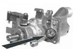
Light the burner and turn it to the minimum position ◦. Extract the gas tap knob and turn the adjustment screw at the side of the tap rod until the correct minimum flame is achieved.
Refit the knob and verify that the burner flame is stable (turning the knob rapidly from the maximum to the minimum position the flame must not go out). Repeat the operation on all the gas taps.
natural_image
Mechanical assembly component with no visible text or symbols
6. CONTROL PANEL
All the cooker controls are grouped together on the front panel. The symbols used are described in the table below.


OVEN THERMOSTAT KNOB

TIMER KNOB

FRONT LEFT-HAND BURNER

REAR LEFT-HAND BURNER

FRONT CENTRAL BURNER

REAR CENTRAL BURNER

CENTRAL BURNER
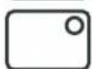
REAR RIGHT-HAND BURNER
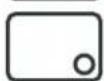
FRONT RIGHT-HAND BURNER
HOB BURNERS CONTROL KNOB
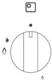
To light the flame, press the knob and turn it counterclockwise to the minimum flame symbol . To adjust the flame, turn the knob to the zone between the maximum ( ) and minimum ( ) settings. To turn off the burner, turn the knob to the position.
TIMER KNOB
In order to use the timer, the buzzer must be set by turning the knob in a clockwise direction. The numbers correspond to minutes (maximum ^120 minutes). Adjustment is progressive and intermediate positions between the figures can be used. The end of cooking buzzer does not interrupt operation of the oven.d
√

This knob allows the gas burner inside the oven to be lit. The cooking temperature is selected by turning the knob counterclockwise to the desired setting, between 120. and 260.
To learn how to light the gas oven, see paragraph 8.3 Using the gas oven.
°C

°C


Instructions for the user
7. USING THE COOKING HOB
7.1 Lighting the hob burners
Before lighting the hob burners, check that the flame-spreader crowns are correctly in place with their respective burner caps, making sure that the holes A in the flame-spreaders are aligned with the plugs and thermocouples.
Before lighting the burners lift the glass lid ; before closing it again, turn off all the burners and wait for them to cool.

The optional pan stand B is for use with woks.

The burner controlled by each knob is shown next to the knob.
The appliance is equipped with an electronic ignition device. Simply press the knob and turn it counterclockwise to the minimum flame symbol o, until it lights. If it does not light in the first 15 seconds, position the knob on 0 and wait at least 60 seconds before trying to light it again.
On valved models, once the burner is lit, keep the knob pressed for a few seconds to give the thermocouple time to heat up. The burner may go out when the knob is released: in this case, the thermocouple has not heated up sufficiently.
Wait a few moments and repeat the operation keeping the knob pressed for a longer time. This is not necessary on burners that are not equipped with thermocouple.
natural_image
Simple circular diagram with vertical lines and symbols, no readable text or labels
On models with thermocouple, if the burners should go out accidentally a safety device will be tripped, cutting off the gas supply even if the gas tap is open. In this case, turn the knob to the OFF position and wait at least 60 seconds before trying to light the burner again.
7.2 Practical hints for using the hob burners

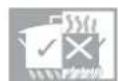
For better burner efficiency and to minimise gas consumption: use pans with lids and of suitable size for the burner, so that the flames do not reach up the sides of the pan (see paragraph 8.3 Using the gas oven. Once the contents come to the boil, turn down the flame far enough to prevent the liquid from boiling over. To prevent burns or damage to the hob during cooking, all pans or griddle plates must be placed inside the perimeter of the hob. All pans must have smooth, flat bottoms. Take the greatest care when using fats or oils since they may catch fire if overheated. If the flame accidentally goes out, turn off the control knob and wait at least 1 minute before trying to re-light the burner.

Caution: Glass lids may shatter when heated. Turn off all the burners before shutting the lid
7.3 90cm cooker pan diameters
Container t able(use flat-bottomed Saucepans)

| Burner | φmin Saucepan (mm) | φmax Saucepan (mm) |
| Auxiliary | 90 | 160 |
| Semi-rapid | 130 | 180 |
| Fish pan | 310× 140 | 380× 230 |
| Rapid | 150 | 260 |
| Triple ring | 210 | 260 |

Instructions for the user
8. USING THE OVEN
8.1 Warnings and general advice
When using the oven and the various heating elements for the first time, they should be heated to the maximum temperature (265) for long enough to burn off any oily residues left by the manufacturing process, which might contaminate foods with unpleasant smells.

WARNING: the gas oven must be lit with the oven door open. The oven is equipped with a safety system that blocks ignition of the burner if the door is closed. If you make a mistake in the lighting procedure, open the oven door and wait a few moments before trying to light it again.

WHILE COOKING DESSERTS AND VEGETABLES PPING FROM THE BOTTOM OF THE DOOR COULD OCCUR. THIS IS A NATURAL PHYSICAL PHENOMENON WHICH MAINLY OCCURS WHEN PREHEATING HAS NOT TAKEN PLACE. IN ORDER TO AVOID THIS, OPEN THE DOOR A COUPLE OF TIMES WHILE COOKING, TAKING GREAT CARE.

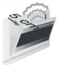
To prevent any steam in the oven from creating problems, open the door in two stages: half open (5 cm approx.) for 4-5 seconds and then fully open. To access food, always leave the door open as short a time as possible to prevent the temperature in the oven from falling and ruining the food.
natural_image
Illustration of a computer monitor with a gear and number 15 on top, no text or symbols present8.2 Using the gas oven
8.2.1 Electronic spark ignition
Open the oven door fully, press the thermostat knob and turn it counterclockwise to the maximum temperature; the electrical spark ignition is activated automatically. When the oven is lit, keep the knob pressed down for a few seconds to allow the thermocouple to heat up.
If the burner does not ignite after 15 seconds, interrupt the attempt to light it, oper the oven door completely and do not try to light it again for at least 1 minute.
°C

8.2.2 Manual ignition
Open the oven door fully and turn the thermostat knob while keeping it pressed in. Bring a lighted match close to the mouth of the flame pipe A at the centre of the oven surface and press the thermostat knob Once it is lit, keep the knob pressed down for a few seconds to allow the thermocouple to heat up and make sure that it has remained lit by looking through the inspection hole B. The cooking temperature is selected by turning the knob clockwise to the desired setting between MIN and MAX.


If the burner is extinguished accidentally, a safety valve will be activated to interrupt the flow of gas. To light it again, first turn the knob to the OFF position (●) and wait for about one minute. Then relight the gas following the normal procedures.
The use of a gas cooking appliance results in the production of heat and moisture in the room in which it is installed. Ensure that the kitchen is well ventilated: keep natural ventilation holes open or install a mechanical ventilation device (mechanical extractor hood).
Prolonged intensive use of the appliance may call for additional ventilation, for example opening of a window, or more effective ventilation, for example increasing the level of mechanical ventilation where present
8.3 Using the electric grill
To use this function you must first extinguish the oven burner by moving the relevant knob to the ● position and then turning the selector to the ☐ position. It is not possible to operate the gas oven and the grill at the same time.
°C

How to use the grill

When the oven has come on, confirmed by the red light switching on, leave it to heat up for 5 minutes before placing foods inside.
Foods must be seasoned before cooking. Foods should also be coated with oil or melted butter before cooking. Use the oven tray to collect juice.
The foods to be cooked must be placed on the oven rack, which must then be placed on one of the runners fitted in the various types of ovens, following the guidelines below:

natural_image
Diagram of a kitchen drawer with numbered labels pointing to different parts (no text or symbols present)| FOODS | RACK ON THE SHELF |
| Flat, thin pieces of meat | 3 |
| Rolled roasts | 2 - 3 |
| Poultry | 2 - 3 |
PRECAUTIONS

Grilling processes must never last more than 60 minutes.

In models with an electric or gas oven, the oven door must be closed during grill cooking operations.
To prevent hazardous overheating, the appliance's glass lid must always be raised when using the oven or grill.
Accessible parts may be very hot during and after use of the grill; keep children well away from the appliance.
When using the oven, remove all unused plates and racks from its interior.
During cooking, do not cover the bottom of the oven with aluminium or tin foil and do not place pans or oven plates on it as this may damage the enamel coating. If you wish to use greaseproof paper, place it so that it will not interfere with the hot air circulation inside the oven.
8.4 Storage compartment (only on some models)
The storage compartment is in the bottom of the cooker, underneath the oven. To open it, pull on the top of the door.
Never use it to store flammable materials such as rags, paper, etc.; it is intended for storing the appliance's metal accessories only.


Do not open the storage compartment when the oven is on and still hot. The temperatures inside it may be very high.

Never use it to store flammable materials such as rags, paper, etc.; it is intended for storing the appliance's metal accessories only.
9. AVAILABLE ACCESSORIES
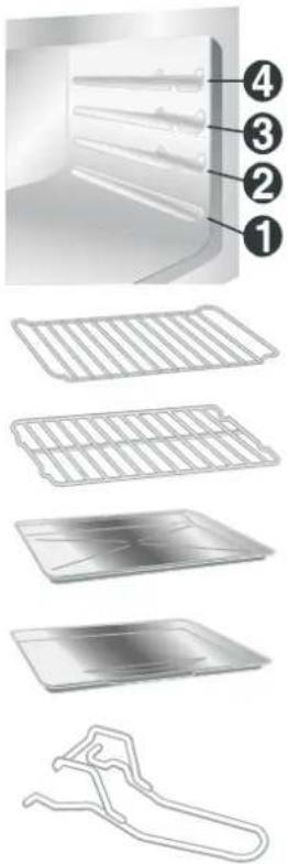
The oven features 4 runners for positioning plates and racks at different heights.
Oven rack: for cooking food inside dishes, small cakes, roasts or foods that require slight grilling.
Plate rack: for placing on top of a plate for cooking foods which may drip.
Oven plate: useful for collecting fat from foods placed on the rack above.
Baking plate (on some models only): useful for cooking cakes, pizza and baked desserts.
Chromium-plated gripper: useful for removing hot racks and plates.
 | The chromium-plated gripper is a very useful accessory in the kitchen; as well as guaranteeing a solid grip on plates and racks, it avoids direct contact (which cannot be avoided when using fabric pot holders or oven gloves). | |
 | Not all accessories are provided on some models.Accessories available on requestThe bottom skirting and the self cleaning oven panels can be requested from Authorised Service Centres. | |
 | The oven accessories intended to come into contact with food are made of materials that comply with the provisions of Directive 89/109/EEC, dated 21/12/88 and of Decree Law 108, dated 25/01/92. |
Instructions for the user

10.CLEANING AND MAINTENANCE

Before performing any operations the appliance. requiring access to powered parts, switch off the power supply to

Do not use a steam jet for cleaning the inside of the oven.

To keep stainless steel in good condition it should be cleaned regularly after every use of the cooker, after it has cooled.
10.1 Ordinary daily cleaning
To clean and preserve the stainless steel surfaces, always use only specific products that do not contain abrasives or chlorine-based acids.
How to use: pour the product on a damp cloth and wipe the surface, rinse thoroughly and dry with a soft cloth or deerskin.
10.1.1 Food stains or residues
Do not use metallic sponges or sharp scrapers: they will damage the surface.
Use normal non-abrasive products and a wooden or plastic tool if necessary. Rinse thoroughly and dry with a soft cloth or deerskin.
Do not allow residues of sugary foods (such as jam) to set inside the oven. If left to set for too long, they might damage the enamel lining of the oven.


10.2 Cleaning the parts of the cooking hob
10.2.1 Pan stands
Remove the pan stands and clean them with warm water and non-abrasive detergent, making sure to remove any encrustation. Replace them on the cooking hob.
Continuous contact between the pan stands and the flame can cause modifications to the enamel over time in those parts exposed to heat. This is a completely natural phenomenon which has no effect on the operation of this component.

Warning:
If using cast iron pan stands (optional not supplied), at the end of cooking using pans with aluminium bases, you may find white residues on the pan stands. These residues are usually caused by the pan base rubbing against the pan stand and are difficult to remove with normal cleaning. Using abrasive or excessively aggressive products to clean the pan stand could damage its enamel surface.

Instructions for the user
10.2.2 Burner caps and flame spreader crowns
For easier cleaning, the caps and the flame spreader crowns can be removed; wash them with warm water and a non-abrasive detergent making sure to remove any encrustation and wait until they are perfectly dry.

WARNING: never wash these parts in a dishwasher.
They can be left to soak with warm water and detergent.
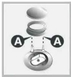
Replace the flame spreader crowns, making sure that they are correctly in place with their respective burner caps, making sure that the holes A in the flame-spreaders are aligned with the igniters and thermocouples.
10.2.3 Igniters and thermocouples
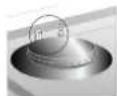
For correct operation, on those models that have them, the igniters and thermocouples must always be perfectly clean. Check them frequently and clean them with a damp cloth if necessary. Remove any dry residues with a wooden toothpick or a needle.
10.3 Cleaning the oven
For best oven upkeep clean regularly after having allowed to cool.
Take out all removable parts.


Clean the oven racks with hot water and non-abrasive detergent. Rinse and dry.
10.4 Cleaning the door glazing
The glass in the door should always be kept thoroughly clean. Use absorbent kitchen roll; remove stubborn dirt with a damp sponge and an ordinary detergent.
11. EXTRAORDINARY MAINTENANCE
The oven may require extraordinary maintenance or replacement of parts subject to wear such as seals, bulbs, and so on. The following instructions describe how to carry out these minor maintenance operations.
Before any intervention that requires access to live parts, disconnect the power supply of the appliance.

11.1 Lubrication of gas oven taps and thermostat

Over time the gas taps and the gas oven thermostat may become difficult to turn and get blocked. Clean them internally and replace the lubrication grease.
This operation must be carried out by a specialised technician.
11.2 Changing the light bulb
Remove the bulb protector A by turning it counterclockwise and change bulb B with a similar one (25 W). Re-fit the bulb protector A.

natural_image
Diagram showing a mechanical component with labeled parts A and B, alongside a magnified view of a cylindrical pipe or duct (no text or symbols present)
Use only oven bulbs (T 300C).
Cleaning the oven do or 11.3 Removing the doors.
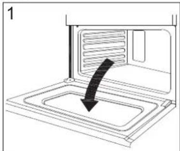
For a more thorough clean, you have to remove the oven door. Choose the removal and assemble method according to different structure of oven door purchased.
Proceed as follows:
- Open the door fully;
- Lift up and turn the small levers located on the two hinges;
● Grip the door on the two external sides and close it approximately half way. Unlock the door by pressing on
the clamps F, then pull the door towards you lifting it out of its seat. To replace the door, reverse this sequence.
natural_image
Diagram of a microwave oven with a black arrow indicating airflow or cooling process (no text or symbols)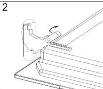
natural_image
Technical line drawing of a mechanical assembly with a lever and base plate (no text or symbols)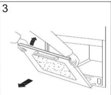
natural_image
Line drawing of a person using a tool to adjust or install a component, with no visible text or symbols11.4 Removing the door seal
To permit thorough cleaning of the oven, the seal may be removed.
Before removing the seal, take off the door as described above. Once the door has been taken off, lift the tabs at the corners as shown in the figure.

natural_image
Diagram of a door with ventilation ducts and airflow direction indicators (no text or symbols)
- Contents
- INSTRUCTIONS FOR USE
- Precautions for use
- INSTRUCTIONS FOR DISPOSAL OUR ENVIRONMENTAL CARE
- INFORMATION FOR USERS:
- INSTALLING THE APPLIANCE
- Electrical connection
- Room ventilation
- Extraction of the products of combustion
- Connection to gas
- Gas connection
- Connection with copper pipe:
- Connection with steel hose:
- ADAPTATION TO DIFFERENT TYPES OF GAS
- Replacement of nozzles on the cooking hob
- Arrangement of the burners on the cooking hob (Mod. 90 cm.)
- BURNERS
- Oven burner adjustment (only for models with a gas oven)
- Replacing the oven burner nozzle
- Primary air adjustment for the oven burner
- FINAL OPERATIONS
- Regulation of the hob burners minimum for natural gas
- Regulation of the hob burners minimum for liquid gas
- Positioning and levelling the appliance (depending on the model)
- Adjustment of the oven burner minimum
- CONTROL PANEL
- HOB BURNERS CONTROL KNOB
- TIMER KNOB
- Instructions for the user
- USING THE COOKING HOB
- Lighting the hob burners
- Practical hints for using the hob burners
- 90cm cooker pan diameters
- USING THE OVEN
- Warnings and general advice
- Using the gas oven
- Electronic spark ignition
- Manual ignition
- Using the electric grill
- How to use the grill
- PRECAUTIONS
- Storage compartment (only on some models)
- AVAILABLE ACCESSORIES
- 10.CLEANING AND MAINTENANCE
- Ordinary daily cleaning
- Food stains or residues
- Cleaning the parts of the cooking hob
- Pan stands
- Burner caps and flame spreader crowns
- Igniters and thermocouples
- Cleaning the oven
- Cleaning the door glazing
- EXTRAORDINARY MAINTENANCE
- Lubrication of gas oven taps and thermostat
- Changing the light bulb
- Cleaning the oven do or 11.3 Removing the doors.
- Removing the door seal
Brand : Campomatic
Model : CB95W
Category : Cooker