
MTP/HDMI U R - AV Extender Extron - Free user manual and instructions
Find the device manual for free MTP/HDMI U R Extron in PDF.


| Product Type | Twisted Pair Universal Receiver |
| Brand | Extron |
| Model | MTP/HDMI U R |
| Category | AV Extender |
| Video Inputs | 1 MTP (RJ-45) analog, 2 RJ-45 digital |
| Video Outputs | HDMI, 15-pin HD RGB, 3 BNC component, BNC composite, 4-pin mini DIN S-video |
| Audio Output | 5-pin captive screw dual mono |
| Control | RS-232 pass-through on 3-pin and 5-pin captive screw connectors |
| Power Supply | 12 VDC, 0.8 A; external 100-240 VAC, 50-60 Hz |
| Maximum Digital Resolution | 1920x1200 or 1080p @ 60 Hz |
| Maximum Analog Resolution | 2048x1080 or 1080p @ 60 Hz |
| Digital Transmission Distance | Up to 200 ft (61 m) on CAT 5/5e/6 or STP cable |
| Analog Transmission Distance | Up to 500 ft (152 m) for 1024x768; up to 400 ft for higher resolutions |
| Enclosure | Metal |
| Mounting Options | Rack, wall, pole, under-desk, through-desk (with optional kits) |
| Cooling | Convection, no vents |
| Operating Temperature | +32 to +122 °F (0 to +50 °C) |
| Storage Temperature | -40 to +158 °F (-40 to +70 °C) |
| Humidity | 10% to 90% noncondensing |
| Included Accessories | Rubber feet (4), 12 VDC 1 A power supply (PS 1210 C), 3-pin captive screw connector, IEC power cord, setup guide |
| Optional Accessories | Rack shelves (RSU 129, RSU 126), mounting kits (PMK 200/350, MBU 125, MBD 129), cables |
| Compliance | FCC Class A, CE, UL guidelines |
Frequently Asked Questions - MTP/HDMI U R Extron
User questions about MTP/HDMI U R Extron
0 question about this device. Answer the ones you know or ask your own.
Ask a new question about this device
Download the instructions for your AV Extender in PDF format for free! Find your manual MTP/HDMI U R - Extron and take your electronic device back in hand. On this page are published all the documents necessary for the use of your device. MTP/HDMI U R by Extron.
USER MANUAL MTP/HDMI U R Extron
MTP Twisted Pair Universal Receiver

Precautions
Safety Instructions • English
This symbol is intended to alert the user of important operating and maintenance (servicing) instructions in the literature provided with the equipment.
This symbol is intended to alert the user of the presence of uninsulated dangerous voltage within the product's enclosure that may present a risk of electric shock.
Caution
Read Instructions • Sound and understand all costly and operating instructions before using the equipment. Return Instructions • The safety instructions should be kept for future reference
Follow Waimings • Follow all screenings and interviews posted on the equipment or in current information.
Avoid Attachments • Do not use tools or attachments that are not recommended by the equipment manufacturers because they may be hazardous.
Power sources • This equipment should be operated only from the power source indicated on the product. The equipment is intended to be used with a male power system with a grounded medium) conductor. The third (proanging) sink is a safety feature, but not allowed to happen or disclose it.
Power disconnection * to remove power from the equipment safety, moves all power needs from the seat of the equipment or the desktop power model (leduct) or from the power source expacts (soil plug).
Power cord protection. Power cards should be counted so that they are not likely to be met-pet on or pitched by some placed upper or antireal there.
Servicing • Better all servicing to qualified service personnel. There are no conservationable parts inside. To prevent the risk of shock, do not want to survive this equipment yourself, but any opening or remitting current may increase you to dangerous value or other rewards.
Slots and openings • If the equipment for clubs or links in the entrance, these are prepared to present, equivalent of service to components inside. These contracts manufacturers be blocked by other agents.
Lithium battery * Thus is a danger of explosion of battery to increase its output. Relocation only with its same or equivalent type recommended by the manufacturer. Disperse of need between according to the manufacturer's instructions.
Avertissement
This equipment has been tested and found to comply with the limits for a Class A digital device, pursuant to part 15 of the FCC Rules. Operation is subject to the following two conditions:
- This device may not cause harmful interference.
- This device must accept any interference received, including interference that may cause undesired operation.
The Class A limits are designed to provide reasonable protection against harmful interference when the equipment is operated in a commercial environment. This equipment generates, uses, and can radiate radio frequency energy and, if not installed and used in accordance with the instruction guide, may cause harmful interference to radio communications. Operation of this equipment in a residential area is likely to cause harmful interference, in which case the user will be required to correct the interference at his own expense.
NOTE: This unit was tested with shielded cables on the peripheral devices. Shielded cables must be used with the unit to ensure compliance with FCC emissions limits.
Symbol Convention
The following symbols are used throughout the guide and carry the following meanings:
TIP: A Tip provides a suggestion to make setting up or working with the device easier.
NOTE: A Note draws attention to important information.
Contents
Introduction 1
MTP/HDMI U R Description 1
Cabling 3
Rear Panel Cabling 3
Wiring Connectors 7
Digital Connector Pin Connector 7
HDMI Connector Pin Assignments 7
Control Connector Wiring 8
Operation 9
Front Panel Overview 9
Level and Peaking 10
Signal Detection.... 10
Setting the Jumpers 11
Setting JMP1 for RS-232 Communication ..... 11
Setting JMP2 and JMP3 to Positive Vertical
and/or Horizontal Sync Polarity 12
Reference Information 13
Part Numbers and Accessories 16
Included Parts 16
Optional Parts 16
Mounting 17
Wall Mounting 17
Pole Mounting 17
Tabletop Placement 17
Rack Mounting 18
UL Guidelines for Rack Mounting 18
Rack Mounting Procedure 18
Under-desk Mounting 18
Through-desk Mounting 18
Introduction
This guide contains information about the Extron® MTP/HDMI U R Twisted Pair Universal Receiver with instructions for experienced installers on how to install, configure, and operate the equipment.
In this guide the following terms are applicable:
- "Transmitter" refers primarily to an MTP transmitter, but could also include an HDMI 201 Tx transmitter.
- "Receiver" refers to the MTP/HDMI U R receiver.
MTP/HDMI U R Description
The Extron MTP/HDMI Universal Receiver is used for long-distance distribution of digital and analog RGB, component (bi-/tri-level), S-video, or composite video signals over twisted pair cables. The receivers auto detect video formats and RS-232/audio signals, enabling the signal to be output on the appropriate rear panel connector.
The MTP/HDMI U R is part of the Extron line of twisted pair transmitters, receivers, and associated video accessories.
The MTP/HDMI U R receives digital or analog signals on RJ-45 connectors over Extron A/V UTP cable, Category (CAT) 5/Se/6 or Extron DTP26 shielded twisted pair (STP), unshielded twisted pair (UTP), or foil shielded twisted pair (FTP) cable.
They are compatible with these Extron devices:
• All MTP transmitters, DAs, and switchers
• DVI 201 and HDMI 201 transmitters
The MTP/HDMI U R ships with an external desktop 12 V, 1 A power supply that accepts 100 to 240 VAC, 50 Hz or 60 Hz input.
A summary table of the MTP/HDMI U R connectivity is shown below.
| Feature Connectivity | ||
| Digital.outputHDMI.(1) |  | |
| RGBHV,.RGBS.output15-pin.HD.(1) | 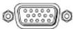 | |
| Component.video.(Y,.R-Y,.B-Y).output | BNCs.(3) | 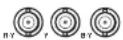  |
| Composite.video.outputBNC.(1) | [42SH] [8KSS] | |
| S-video.output4-pin.mini.DIN.(1) | [7AG2] Y/C | |
| Dual.mono.audio.output5 | pin.captive.screw.(1) | [KY97] |
| RS-232.connectivity | 5-pin.captive.screw.(1) 3-pin.captive.screw. |  |
Cabling
This section describes how to connect cables to the MTP/HDMI U R.
- Rear Panel Cabling
- Wiring Connectors
Rear Panel Cabling
The illustration below shows the rear panel features of the MTP/HDMI U R.
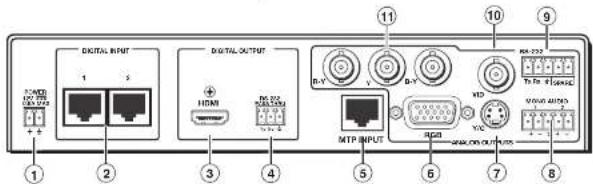
Figure 2. MTP/HDMI U R Rear Panel Features
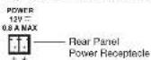
① Power input — Connect the standard IEC power cord from a 100 to 240 VAC, 50-60 Hz power source into the 12 VDC, 0.8 A power receptacle. Wire the 2-pole captive screw connector as shown below.
CAUTION: Always use a power supply supplied by or specified by Extron. Use of an unauthorized power supply voids all regulatory compliance certification and may cause damage to the supply and the end product. Unless otherwise stated, the AC/DC adapters are not suitable for use in air handling spaces or in wall cavities. The installation must always be in accordance with the applicable provisions of National Electrical Code ANSI/NFPA 70, article 75 and the Canadian Electrical Code part 1, section 16. The power supply shall not be permanently fixed to building structure or similar structure.
NOTE: Do not tin the power supply leads before installing them in the direct insertion connector. Tinned wires are not as secure and could be pulled out.
② Digital signal input — Connect one end to the two separate twisted pair cables from the output of the transmitter to these two female RJ-45 twisted pair input connectors.
NOTE: The transmission distance varies greatly depending on the signal resolution and on the type of cable, graphic card, and display used in the system. DO.NOT use Extron UTP23SF-4 Enhanced Skew-Free™ A/V cable to link the transmitter and receiver. Use of this cable will cause problems with the digital signal input side of the MTP/HDMI U R receiver. It is important to ensure the cable from output 1 on the transmitter is connected to input 1 on the receiver. Likewise, output 2 on the transmitter must be connected to input 2 on the receiver.
| Maximum Transmitter to Receiver Distance (Digital Signals)8-bit Color Depth | |||
| Resolution UTP | CAT 5/5e/6Feet (Meters) | STP CAT 5/5e/6Feet (Meters) | DTP26Feet (Meters) |
| 1024x768 | 200.(61)200.(61) | 200.(61) | |
| 720p200.(61) | 200.(61)200.(61) | ||
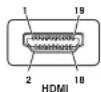
③ Digital signal output — The MTP/HDMI U R outputs a digital HDMI signal through this female HDMI connector. See the "HDMI Connector Pin Assignments" section, for pin wiring details.
HDMI

④ RS-232 Control Pass-thru connector — Connect a serial communications port to this 3.5 mm, 3-pole captive screw connector for bidirectional RS-232 communication (digital side). See the "Control Connector Wiring" section, to wire the connector.
NOTE: The RS-232 connector can also transmit one-way modulated infrared (IR) signals.
⑤ Analog signal input — Connect an MTP transmitter (or a DA or a switcher) using twisted pair cable to this RJ-45 connector.
CAUTION: Do not connect the twisted pair input cables to a LAN port, or connect a LAN cable to the digital or MTP input ports.
NOTE: The transmission distance varies greatly depending on the signal resolution and on the type of cable, graphic card, and display used in the system.
| Maximum Transmitter to Receiver Distance (Analog Signals) | ||||
| Video Format With Pre-Peak Off Feet (Meters) | With Pre-Peak On Feet (Meters) | Max. Distance (High Quality) Feet (Meters) | Max. Distance (Variable Quality) Feet (Meters) | |
| Composite, S-video, Component.Video | 800.(245)1000.(300) | |||
| 640.x.480<300.(90)>350.(105)700.(215)750.(240) | ||||
| 800.x.600<300.(90)>350.(105)550.(165)650.(200) | ||||
| 1024.x.768*<300.(90)>350.(105)500.(150)600.(185) | ||||
| 1280.x.960<300.(90)>350.(105)400.(120)500.(150) | ||||
| 1280.x.1024*<250.(75).>300.(90).350.(105)450.(135) | ||||
| 1360.x.765<250(75).>300.(90).400.(120)500.(150) | ||||
⑥ ⑦ ⑩ ⑪ Analog signal outputs — Connect suitable devices for analog signals: RGBHV, RGBS, component (Y, R-Y, B-Y), S-video (Y/C), and composite video.
NOTE: The video signals detected on the MTP input are directed to the appropriate analog outputs.
Connect as shown below:
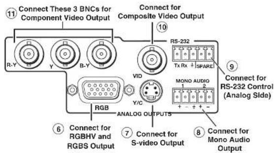
Figure 6. Analog Output Connections
⑧ Audio output — Connect a suitable audio device to this 5-pole captive screw connector for a balanced or unbalanced, dual mono audio signal.
NOTE: The audio signal is detected on the analog MTP twisted pair input and then distributed to the audio output connector.
Wire the connector as shown below:
CAUTION: For unbalanced output, connect both sleeves to the center (ground)
Wiring Connectors
Digital Connector Pin Connector
The figure below details the recommended termination of TP cables with RJ-45 connectors in accordance with either the TIA/EIA T 568A or the TIA/EIA T 568B wiring standard.
RJ-45 Connector
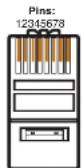
↑
Insert Twisted
Pair Wires
| Pin | TIA/EIA T568 AWire color | TIA/EIA T568 BWire color | Signal | |
| RJ-45 #1 | RJ-45 #2 | |||
| 1 | White-green | White-orange | Data 0+ | CEC |
| 2 | Green | Orange | Data 0- | HPD |
| 3 | White-orange | White-green | ID Clock+ | RS-232TX |
| 4 | Blue | Data 1+Blue | DDC Clk | |
| 5 | White-blue | White-blue | Data 1- | +12 V |
| 6 | Orange | Green | ID Clock- | RS-232RX |
| 7 | White-brown | White-brown | Data 2+ | DDC data |
| 8 | Brown | Brown | Data 2- | Ground |
Figure 8. Digital Connector Wiring
NOTE: Whichever standard (TIA T 568A or T568 B) is used, the same standard must be used on both ends of the cable.
HDMI Connector Pin Assignments
The table below defines the pinout for the HDMI protocol.

Control Connector Wiring
For the 3-pole (digital side) RS-232 pass-through connector, wire as shown below:
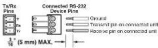
Figure 10. 3-pole RS-232 Connector Wiring
For the 5-pole (analog side) RS-232 connector, wire as shown below:
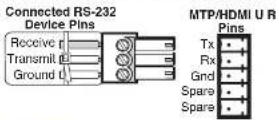
Figure 11. 5-pole RS-232 Connector Wiring
CAUTION: The length of the exposed (stripped) copper wires is important. The ideal length is 3/16 inch (5 mm). Longer bare wires can short together and shorter wires are not as secure in the connectors and could be pulled out.
NOTE: Do not tin the wires before installing them in the connector. Tinned wires are not as secure and could be pulled out.
Operation
This section of the guide discusses the operation of the MTP/HDMI U R and cover the following points:
- Front Panel Overview
• Level and Peaking - Signal Detection
- Setting the Jumpers
Front Panel Overview
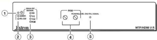
Figure 12. MTP/HDMI U R Front Panel Features
① LED indicator — A solid green light indicates the unit is receiving power from the connected power supply.
② Audio and RS-232 LEDs — These two LEDs light when either audio or RS-232 signals are detected.
③ Analog Signal presence LED indicators — These four LEDs (VID, Y/C, YUV, or RGB)
Level and Peaking
The Level adjustment knob (which can be used only on the analog signal) alters the video output voltage to affect the brightness of the displayed image. Adjust the knob while viewing the image to set the level that provides the best picture quality.
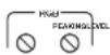
The Peaking adjustment knob adjusts the image sharpness, and is applicable only to the analog side of the device. Increased peaking can compensate for mid- and high frequency detail loss from low bandwidth systems or capacitance in long cable runs. The minimum setting (fully counterclockwise) provides no peaking, while the maximum setting (fully clockwise) provides 100% peaking.
NOTE: To avoid possible video loss due to errors in the video format detection, the user should always start with minimal level and peaking, then only increase values as required.
To adjust level and peaking:
- Connect an oscilloscope (preferred) or a monitor (acceptable) to the RGB output of the MTP receiver.
- If using an oscilloscope, apply a white field test pattern to the MTP transmitter input. If using a monitor, apply a grayscale or color bars test pattern to the input.
NOTE: The signal applied should be an RGB signal.
TIP: The Extron VTG 300 or VTG 400 is recommended to provide the test pattern.
The receiver detects the RGB signal.
- Observe the oscilloscope or the monitor with a critical eye while you adjust the front panel input level and peaking controls to compensate for signal loss between the transmitter and the MTP/HDMI U R.
- Disconnect the oscilloscope or monitor, and the test generator, connected in step 1.
Signal Detection
Setting the Jumpers
The MTP/HDMI U R receiver has three jumpers on the main board:
- Jumper 1 (JMP1) controls RS-232 directional communication (bidirectional or unidirectional)
JMP1 is in closed position by default, and configured to send serial data both ways, transmitter-to-receiver, receiver-to-transmitter (bidirectional).
- Jumpers 2 (JMP2) and 3 (JMP3) control vertical and horizontal sync respectively (negative or positive). Jumpers 2 and 3 are in open position by default and configured for negative sync (H-, V-).
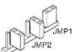
JMP3
Default settings as viewed from rear
Setting JMP1 for RS-232 Communication
JMP1 can be repositioned to enable unidirectional (one-way, pass through) communication as follows:
- If applicable, disconnect all cables, remove the receiver from its installation location, and remove any mounting brackets installed.
- Remove the two screws from each side of the receiver (four screws total) and lift the top cover off of the receiver.
- Locate jumper JMP1 on the main board. Remove and reposition it over one pin (see figure below).

Reposition the jumper block to cover one pin.
Figure 13. Setting Jumper 1 to Unidirectional
NOTE: If JMP2 and JMP3 also need resetting, see the "Setting JMP2 and JMP3 to Positive Vertical and/or Horizontal Sync Polarity" section on page 12, before replacing the top cover.
Setting JMP2 and JMP3 to Positive Vertical and/or Horizontal Sync Polarity
Horizontal and vertical sync polarity can be set by configuring the internal jumpers on the MTP/HDMI U R main board. The default setting is negative sync (H-V-), and can be changed by resetting the position of the jumpers as follows:
- If the unit is not already open, follow steps 1 and 2 in the "Setting JMP1 for RS-232 Communication" section.
- Locate JMP2 and JMP3 on the main board. Remove and reposition the jumper block over both pins (see figure below). Repeat as desired for the second jumper.
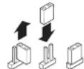
Reposition the jumper
block to cover both pins
Figure 14. Inverting Sync with Jumpers JMP2 and JMP3
- Replace the top cover and follow steps 4 and 5 in the "Setting JMP1 for RS-232 Communication" section.
To reset the syncs to default, open the unit and place the applicable jumper block to cover only a single pin.
Reference Information
This section provides information about:
- Specifications
• Part Numbers and Accessories
Specifications
Video
MTP input
Gain Unity
Maximum resolution
Analog Up to 2048x1080 or 1080p @ 60 Hz
Signal transmission distance, analog
| MTP/HDMI U RAnalog Signal Maximum Transmission Distances | |
| Resolutions | |
| 1024x768 @ 60 Hz | Up to 500' (183 m) |
| 1920x1200, 2048x10801080p @ 60 Hz | Up to 400' (122 m) |
HDMI digital input
Maximum data rate 4.95 Gbps (1.65 Gbps per color)
Maximum pixel clock 165 MHz
Maximum resolution
Digital Up to 1920x1200 or 1080p @ 60 Hz
Signal transmission distance, digital
HYDINSHU
Video input
Number/signal type
MTP input 1 set of proprietary analog signals
HDMI digital input 1 set of proprietary digital signals
Connectors
MTP input 1 female RJ-45
HDMI digital input 2 female RJ-45
Video output
Number/signal type
Analog output 1 RGBHV, RGBS, component video (bi-level and tri-level), S-video, composite video
(follows input type)
HDMI digital output .... 1 single link HDMI (or DVI-D^)
Connectors
Analog output 1 female 15-pin HD for RGB
3 female BNC for Y, R-Y, B-Y
1 female 4-pin mini DIN for S-video (Y/C)
1 female BNC for composite video
HDMI digital output ...... 1 female HDMI type A
Nominal levels Analog outputs:
1 Vp-p for Y of component video and S-video, and for composite video
0.7 Vp-p for RGB and for R-Y and B-Y of component video
0.3 Vp-p for C of S-video
Minimum/maximum levels ...... Analog outputs: 0.8 V to 1.2 Vp-p
Impedance ...... Analog outputs: 75 ohms (during video output only)
Return loss ...... Analog outputs: <-30 dB @ 5 MHz (during video output only)
DC offset Analog outputs: < ± 20mV with input at 0 offset
Sync — analog outputs
Output type ...... RGBHV, RGBS, component video (bi- or tri-level)
Standards NTSC 3.58, NTSC 4.43, PAL, SECAM
Output level 4.0 V to 5.0 Vp-p, unterminated
Output impedance 87 ohms (24 mA)
Polarity ...... Positive or negative (selectable)
Audio — from MTP input
Control/remote — external device (pass-through) from the HDMI input
Serial control port input/output ..... RS-232 via (1) 3.5 mm, 3 pole captive screw connector
Baud rates..... Up to 38400 bps at up to 600° (183 m) (Higher data rates and distances are possible. Performance varies based on baud rate and cable length.)
NOTE: Protocol is mirrored between the transmitter and the receiver.
Serial control pin configuration ..... Captive screw connector: 1 = Tx, 2 = Rx, 3 = GND
Control/remote — external device (pass-through, unidirectional or bidirectional) from the MTP input
Serial control port input/output ..... RS-232 via (1) 3.5 mm, 5 pole captive screw connector (3 poles are used)
Baud rates..... Up to 38400 bps at up to 600' (183 m) (Higher data rates and distances are possible.
Performance varies based on baud rate and cable length.)
NOTE: Protocol is mirrored between the transmitter and the receiver.
Serial control pin configuration ..... Captive screw connector: 1 = Tx, 2 = Rx, 3 = GND
General
Recommended cable type ...... Shielded or unshielded
MTP input CAT 5/5e/6
HDMI digital input CAT 5/5e/6, Extron DTP26
External power supply 100 VAC to 240 VAC, 50-60 Hz, external; to 12 VDC, 1 A, regulated
Power input requirements 12 VDC, 0.8 A
Temperature/humidity ...... Storage: -40 to +158 °F (-40 to +70 °C) / 10% to 90%, noncondensing
Operating: +32 to +122 °F (0 to +50 °C) / 10% to 90%, noncondensing
Cooling ...... Convection, no vents
Thermal dissipation
115 VAC, 60 Hz 16.7 BTU/hr
240 VAC, 50 Hz 18.1 BTU/hr
Mounting
Rack mount .... Yes, with optional 1U rack shelf
Furniture mount .... Yes, with optional under-desk mounting kit
Pole mount Yes, with optional projector mounting kit
Enclosure type ...... Metal
Part Numbers and Accessories
Included Parts
| Description Part Number | |
| MTP/HDMI U R 60-1048-01Rubber feet (not attached) (4)External, 12 VDC, 1 A power supply PS 1210 C 70-775-013.5 mm, 3-pole captive screw connector for RS-232 connectionsIEC power cord (1)Setup Guide - MTP/HDMI U R |
Optional Parts
| Description Part Number | |
| RSU 129 (1U, 9.5" deep rack shelf kit) 60-190-01RSB 129 (1U, 9.5" deep basic rack shelf) 60-604-02RSU 126 (1U, 6" deep rack shelf kit) 60-190-10RSB 126 (1U, 6" deep basic rack shelf) 60-604-11MBU 125 (under-desk mounting kit) 70-077-01PMK 200, (pole mount kit) 70-077-04PMK 350, (pole mount kit) 70-563-03MBD 129 (through-desk mounting kit) 70-077-02 | |
| HDMI Pro Series cable 26-650-xxSkew-freeTM UTP cable (non-plenum) 22-141-03Skew-free UTP cable (plenum) 22-142-03VGA M-M MD cables (15-pin HD connectors) 26-238-xxMHR-2 S-video cable 26-316-xx |
Mounting
This section outlines the various mounting options available for the MTP/HDMI U R:
- Wall Mounting
- Pole Mounting
- Tabletop Placement
- Rack Mounting
• Under-desk Mounting
• Through-desk Mounting
Wall Mounting
The MTP/HDMI U R can be mounted on a wall, using the optional Extron WMK 150 wall mounting kit. This allows the unit to be concealed close to wall-mounted flat screen monitors. To mount the unit on the wall, follow the instructions provided with the WMK 150 kit.
Pole Mounting
The MTP/HDMI U R can be mounted on a projector pole using the optional Extron PMK 200 or PMK 350 pole mount kits. This allows the unit to be installed above or close to projectors. To mount the unit on the pole, follow the instructions provided with the pole mount kit.
Tabletop Placement
Rack Mounting
UL Guidelines for Rack Mounting
The following Underwriters Laboratories (UL) guidelines are relevant to the safe installation of these products in a rack:
- Elevated operating ambient temperature — If the unit is installed in a closed or multi-unit rack assembly, the operating ambient temperature of the rack environment may be greater than room ambient temperature. Therefore, install the equipment in an environment compatible with the maximum ambient temperature (Tma: +122 °F, +50 °C) specified by Extron.
- Reduced air flow — Install the equipment in the rack so that the equipment gets adequate air flow for safe operation.
- Mechanical loading — Mount the equipment in the rack so that uneven mechanical loading does not create a hazardous condition.
- Circuit overloading — Connect the equipment to the supply circuit and consider the effect that circuit overloading might have on overcurrent protection and supply wiring. Appropriate consideration of the equipment nameplate ratings should be used when addressing this concern.
- Reliable earthing (grounding) — Maintain reliable grounding of rack-mounted equipment. Pay particular attention to supply connections other than direct connections to the branch circuit (such as the use of power strips).
Rack Mounting Procedure
The unit can be mounted on optional rack systems, including:
• RSU 129: 9.5" deep, 1U rack shelf kit (part # 60-190-01)
• RSU 126: 6" deep, 1U rack shelf kit (part # 60-190-10)
To mount the device on a rack shelf, follow the instructions provided with the shelf accessories.
Under-desk Mounting
Extron® Warranty
Extron Electronics warrants this product against defects in materials and workmanship for a period of three years from the date of purchase. In the event of malfunction during the warranty period attributable directly to faulty workmanship and/or materials, Extron Electronics will, at its option, repair or replace said products or components, to whatever extent it shall deem necessary to restore said product to proper operating condition, provided that it is returned within the warranty period, with proof of purchase and description of malfunction to:
and Central America:
Extron Electronics
1001 East Ball Road
Anaheim, CA 92805
U.S.A.
Japan:
Extron Electronics, Japan
Kyodo Building, 16 Ichibancho
Chiyoda-ku, Tokyo 102-0082
Japan
Europe, Africa, and the Middle
East:
Extron Europe
Hanzeboulevard 10
3825 PH Amersfoort
The Netherlands
China:
Extron China
686 Ronghua Road
Songjiang District
Shanghai 201611
China
Asia:
Extron Asia
135 Joo Seng Road, #04-01
PM Industrial Bldg.
Singapore 368363
Singapore
Middle East:
Extron Middle East
Dubai Airport Free Zone
F12, PO Box 293666
United Arab Emirates, Dubai
This Limited Warranty does not apply if the fault has been caused by misuse, improper handling care, electrical or mechanical abuse, abnormal operating conditions, or modifications were made to the product that were not authorized by Extron.
NOTE: If a product is defective, please call Extron and ask for an Application Engineer to receive an RA (Return Authorization) number. This will begin the repair process.
USA: (714) 491-1500 Europe: +31.33.453.4040
Δεια: +65 6383 4400 Ianan: +81 3 3511 7655
- Precautions
- Safety Instructions • English
- Caution
- Avertissement
- Symbol Convention
- Contents
- Introduction
- MTP/HDMI U R Description
- Cabling
- Rear Panel Cabling
- Wiring Connectors
- Digital Connector Pin Connector
- HDMI Connector Pin Assignments
- Control Connector Wiring
- Operation
- Front Panel Overview
- Level and Peaking
- To adjust level and peaking:
- Signal Detection
- Setting the Jumpers
- Setting JMP1 for RS-232 Communication
- Setting JMP2 and JMP3 to Positive Vertical and/or Horizontal Sync Polarity
- Reference Information
- Specifications
- Video
- Video input
- Video output
- Sync — analog outputs
- Control/remote — external device (pass-through) from the HDMI input
- Control/remote — external device (pass-through, unidirectional or bidirectional) from the MTP input
- General
- Part Numbers and Accessories
- Mounting
- Wall Mounting
- Pole Mounting
- Tabletop Placement
- Rack Mounting
- UL Guidelines for Rack Mounting
- Rack Mounting Procedure
- Under-desk Mounting
- Extron® Warranty
- and Central America:
- Japan:
- Europe, Africa, and the Middle
- East:
- China:
- Asia:
- Middle East:
Brand : Extron
Model : MTP/HDMI U R
Category : AV Extender