
DVI DL 101 - AV Extender Extron - Free user manual and instructions
Find the device manual for free DVI DL 101 Extron in PDF.


| Product Type | DVI Dual Link Cable Equalizer / AV Extender |
| Brand | Extron |
| Model | DVI DL 101 |
| Dimensions (H x W x D) | 1.0" x 4.3" x 3.0" (2.5 cm x 10.9 cm x 7.6 cm) excluding connectors |
| Weight | 0.5 lbs (0.3 kg) |
| Power Supply | External 12 VDC, 2 A; input 100-240 VAC, 50/60 Hz |
| Power Consumption | 12 W (max) |
| Video Input | 1 dual link DVI-D (on female DVI-I connector) |
| Video Output | 1 dual link DVI-D (on female DVI-I connector) |
| Maximum Data Rate | 10 Gbps total (3.3 Gbps per color) |
| Maximum Pixel Clock | 330 MHz (165 MHz per link) |
| Supported Resolutions | Dual link up to 2560x1600 @ 60 Hz; Single link up to 1920x1200 or 1080p @ 60 Hz |
| Input Cable Length | Up to 200' (61 m) at 2560x1600; up to 275' (84 m) at lower resolutions |
| Output Cable Length | Up to 16.4' (5 m) |
| Equalization | Automatic for up to -40 dB cable loss |
| Impedance | 110 ohms |
| Operating Temperature | +32 to +122 °F (0 to +50 °C) |
| Storage Temperature | -40 to +158 °F (-40 to +70 °C) |
| Humidity | 10% to 90% noncondensing |
| Cooling | Convection, no vents |
| Mounting Options | Rack shelf (optional), under-desk, through-desk, projector pole, tabletop |
| Regulatory Compliance | CE, UL, CUL, C-tick, FCC Class A, VCCI, ICES |
| Warranty | 3 years parts and labor |
| Included Accessories | 12 VDC power supply, IEC power cord, rubber feet, Tweeker screwdriver, user manual |
| Cleaning Instructions | Wipe with dry cloth; do not use liquids or sprays |
| Safety Information | Follow installation guidelines; avoid exposing to moisture; use only provided power supply |
Frequently Asked Questions - DVI DL 101 Extron
User questions about DVI DL 101 Extron
0 question about this device. Answer the ones you know or ask your own.
Ask a new question about this device
Download the instructions for your AV Extender in PDF format for free! Find your manual DVI DL 101 - Extron and take your electronic device back in hand. On this page are published all the documents necessary for the use of your device. DVI DL 101 by Extron.
USER MANUAL DVI DL 101 Extron
Safety Instructions • English
This symbol is intended to alert the user of important operating and maintenance (servicing) instructions in the literature provided with the equipment.
This symbol is intended to alert the user of the presence of unregulated dangerous voltage within the product's enclosure that may present a risk of electric shock.
Caution
Hand instructions • Hand and unenclosed safety and reoperations
2012.11.31
The following table is in English:
Avid Alisthens, Jore: p. keer zubreschilj ar s.
as amended with the optional manufacturer has a line may be
molecular structure of a nuclear
(1) 2017年1月1日
- 2017年1月1日
ЗБУКИЗ СИЙСЕЯ Г.001-2015, 2016, 2017, 2018, 2019, 2020, 2021, 2022, 2023, 2024, 2025, 2026, 2027, 2028, 2029, 2030, 2031, 2032, 2033, 2034, 2035, 2036, 2037, 2038, 2039, 2040, 2041, 2042, 2043, 2044, 2045, 2046, 2047, 2048, 2049, 2050, 2051, 2052, 2053, 2054, 2055, 2056, 2057, 2058, 2059, 2060, 2061, 2062, 2063, 2064, 2065, 2066, 2067, 2068, 2069, 2070, 2071, 2072, 2073, 2074, 2075, 2076, 2077, 2078, 2079, 2080, 2081, 2082, 2083, 2084, 2085, 2086, 2087, 2088, 2089, 2090, 2091, 2092, 2093, 2094, 2095, 2096, 2097, 2098, 2099, 2100
Incorporated group (non-qualified market)
In this period, the square of the following property
For example, the
The following is not a way to be
nabian leoultlequipred, jela irahpomavikjitalaki
(1) Ⅲ-Ⅱ-Ⅲ-Ⅳ-Ⅴ-Ⅵ-Ⅶ-Ⅷ
factual price (r) is cash and the value of the
Apprict on which the mean and upper range of the
- 本次股东大会以现场会议形式召开的股东
In the case, the case is a result of the first outcome. The results are not
sempo#tka nothbom
Ships and openings • If the equipment has a wire or cable in the outside boxes.
product to extract containing clomia composite risk, that group
1.2015年4月28日(星期六)
Linzian Valley - Tram's 2nd place in the commercial property of Zanzhong, which is limited to a sale for any or equivalent property.
la nepracum. Buys pluv zimpiu wazkra to la nepracum.
to find no.
Avertissement
Girardianer Sela Kostanovor & Hypofoch, social development
In the case of the following:
Bierstokes de Lihazbilkes: Let us think a recent project is done.
currently and/or what is the 'excellent quality'
Ceruklindharodoluschis mawak kupas-ster.
The following table is a simple formula:
Buchler, Prince Par Act Report
M. M. M.
mend per 100000. Atr. Center best Japan's electricity. Dalianas as all
provened preclinical reoperation of drug use in the
The following table is in English:
Notes: The following described information is not available.
and following business support for industrial rights
The following table is provided in the image.
P
Advertencia
A. 10.1.2014.
The following table provides the original text:
The following questions are that there is a clear view of the natural and a scaled view of the way, where
The following described text is not possible to be transcribed in the image.
Extron's Warranty
Extron Electronics warrants this product against defects in materials and workmanship for a period of three years from the date of purchase. In the event of malfunction during the warranty period attributable directly to faulty workmanship and/or materials, Extron Electronics will, at its option, repair or replace said products or components, to whatever extent it shall deem necessary to restore said product to proper operating condition, provided that it is returned within the warranty period, with proof of purchase and description of malfunction to:
USA, Canada, South America, Europe, Africa, and the Middle East:
and Central America: Extron Electronics, Europe
-
-
-
-
-
-
-
-
-
-
-
-
-
-
-
-
-
-
-
-
-
-
-
-
-
-
-
-
-
-
-
-
-
-
-
-
-
-
-
- 41.
-
-
-
-
-
-
-
-
-
-
-
-
-
-
-
-
-
-
-
-
-
-
-
-
-
-
-
-
-
-
-
-
-
-
-
-
-
-
on electronics - 100
3821 AH Amersfoort
Anaheim, CA 92805, USA The Netherlands
Asia: Japan;
Extron Electronics, Asia, Extron Electronics, Japan
125 Ice Song Road #01.01
135 Job Seng Road,
I'M Industrial Bldg
Singapore 368363
Kyodo Building
16 Ichibanchy
This Limited Warranty does not apply if the fault has been caused by misuse, improper handling care, electrical or mechanical abuse, abnormal operating conditions or non-Extron authorized modification to the product.
If it has been determined that the product is defective, please call Extron and ask for an Applications Engineer at (714) 491-1500 (USA), 31.33.453.4040 (Europe), 65.6383.4400 (Asia), or 51.3.3511.7655 (Japan) to receive an RA# (Return Authorization number). This will begin the repair process as quickly as possible.
Units must be returned insured, with shipping charges prepaid. If not insured, you assume the risk of loss or damage during shipment. Returned units must include the serial number and a description of the problem, as well as the name of the person to contact in case there are any questions.
Extron Electronics makes no further warranties either expressed or implied with respect to the product and its quality, performance, merchantability, or fitness for any particular use. In no event will Extron Electronics be liable for direct, indirect, or consequential damages resulting from any defect in this product even if Extron Electronics has been advised of such damage.
Please note that laws vary from state to state and country to country, and that some provisions of this warranty may not apply to you.
安全须知·中文

This equipment has been tested and found to comply with the limits for a Class A digital device, pursuant to part 15 of the FCC Rules. Operation is subject to the following two conditions: (1) this device may not cause harmful interference, and (2) this device must accept any interference received, including interference that may cause undesired operation. The Class A limits are designed to provide reasonable protection against harmful interference when the equipment is operated in a commercial environment. This equipment generates, uses, and can radiate radio frequency energy and, if not installed and used in accordance with the instruction manual, may cause harmful interference to radio communications. Operation of this equipment in a residential area is likely to cause harmful interference, in which case the user will be acquired to correct the interference at his own expense.
Table of Contents
Chapter One • Introduction....1-1
About this Manual 1-2
About the DVI DL 101 Cable Equalizer 1-2
Features 1-2
Application Diagrams 1-3
Chapter Two • Installation and Operation ..... 2-1
Mounting the DVI DL 101 2-2
Tabletop use 2-2
Rack mounting 2-2
UL rack mounting guidelines 2-2
Rack mounting procedure 2-3
Under-furniture mounting 2-4
Through-furniture mounting 2-5
Projector mounting 2-6
PMK 300 mounting 2-7
PMK 350 mounting 2-9
Front and Back Panel Features and Connections ...... 2-11
Input cable lengths 2-12
Dual and single link modes 2-12
Enabling the DDC Buffer 2-14
Appendix A • Specifications, Parts, and
Accessories A-1
Specifications - DVI DL ......A-2
Included Parts ......A-4
Optional Accessories ......A-4
Cables and Adapters A-5
Table of Contents, cont'd

DVI DL 101
1 Chapter One
Introduction
About this Manual
About the DVI DL 101 Cable Equalizer
Features
Application Diagram
Introduction
About this Manual
This manual contains information about the Extron DVI DL 101 Dual Link Cable Equalizer and describes how to connect and operate it. The terms "DVI DL" and "equalizer" are used interchangeably throughout this manual to refer to the product.
About the DVI DL 101 Cable Equalizer
The Extron DVI DL 101 is a dual link cable equalizer that extends Digital Visual Interface (DVI) signals beyond the specified cable limits of 15' (5 m). The DVI DL attaches to the end of a long cable run of up to 275' (84 m) for dual link and up to 200' (61 m) for single link.
Placed just before the display in the cable run, it automatically equalizes and drives the signal, eliminating any noise or dropouts, to ensure optimal image quality. It supports all dual link DVI signals up to 330 MHz, including 2560x1600 @ 60 Hz. Also, because dual link is backwards compatible with single link, all single link rates up to 165 MHz, including 1920x1200 and 1080p @ 60 Hz, are also supported.
The DVI DL passes Extended Display Identification Data (FID) information and supports the long distance transmission of HDTV signals with High-bandwidth Digital Content Protection (HDCP) for copy protection of digital television broadcasts and high resolution digital video output from DVD, HD DVD, and Blu-ray Disc players. DDC lines are passed through with the option of active buffering to ensure compatibility among various source and display configurations.
With the appropriate adapters from Extron, the DVI DL is fully compatible with the HDMI digital video, audio, and control standard for audio/video products.
Features
- Power/Signal status indicator — The LED on the front panel lights amber to indicate that power is connected. When a source signal is present, this LED lights green.
-
Optional buffering of DDC/HDCP lines — DDC/HDCP clock and data lines can be actively buffered or passed straight through to the output.
-
DVI output — One female DVI-I connector supports DVI-D output. The acceptable output cable length is 16.4' (5 m).
NOTE Dual link DVI cables must be used for dual link DVI signals. With a single link DVI cable, only single-link signals are possible. - Rack and furniture mounting — The equalizer can be mounted on a rack shelf, or under or through a desk or podium.
- Power supply — An external international power supply with a two-pin captive screw connector accepts 100 to 240 VAC.
Application Diagrams
The following diagrams show examples of how the DVI DL can be connected.
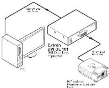
DVI DL application diagram
Introduction, cont'd

DVI DL 101
Chapter Two
Installation and Operation
Mounting the DVI DL 101
Front and Back Panel Features and Connections
Enabling the DDC Buffer
Installation and Operation
Mounting the DVI DL 101
The DVI DL can be mounted on a rack shelf, under or through furniture, attached to a projector pole, or placed on a table top.
Tabletop use
Four sell-adhesive rubber feet are included with the DVI DL. For tabletop use, attach one foot at each corner on the bottom surface of the unit.
Rack mounting
The optional accessories available for rack mounting the DVI DL include the following:
- RSF 123 — 3.5" deep 1U VersaTools * rack shelf kit (part #60-190-20)
- RSB 123 — 3.5" deep 1U VersaTools rack shelf (part #60-604-20)
- RSLU 126 — 6" deep 1U universal rack shelf kit (part #60-190-10)
- RSB 126 — 6" deep 1U basic rack shelf (part #60-604-10)
- RSU 129 — 9.5" deep 1U universal rack shell kit (part #60-190-01)
- RSB 129 — 9.5" deep 1U basic rack shelf (part #60-604-01)
UL rack mounting guidelines
The following Underwriters Laboratories (UL) requirements pertain to the installation of the DVI DL 101 into or onto a rack.
- Elevated operating ambient — If the equipment is installed in a closed or multi-unit rack assembly, the operating ambient temperature of the rack environment may be greater than room ambient. Therefore, consider installing the equipment in an environment compatible with the +122 °F (+50 °C) maximum ambient temperature (1°ma) specified by Extron.
- Reduced air flow — Install the equipment in the rack so that the amount of air flow required for safe operation of the equipment is not compromised.
-
Mechanical loading — Mount the equipment in the rack so that uneven mechanical loading does not lead to a
-
Reliable carthing (grounding) — Maintain reliable grounding of rack-mounted equipment. Pay particular attention to supply connections other than direct connections to the branch circuit (such as the use of power strips).
Rack mounting procedure
On the 6" deep and 9.5" deep rack shelves, the unit can be mounted in the front or the rear of the rack.
1. If rubber feet were previously installed on the bottom of the unit, remove them.
2. Secure the DVI DL on the rack shelf, using two 4-40 x 3/16" screws in opposite (diagonal) corners.
3. Install blank panel(s) or other unit(s) on the rack shelf as desired.
4. Insert the shelf into the rack, aligning the holes in the shelf with those of the rack.
5. Secure the shelf to the rack using the supplied machine screws. This shelf can be mounted in the front or in the rear of the rack.
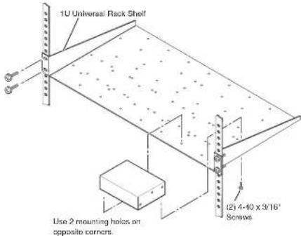
Installation and Operation, cont'd
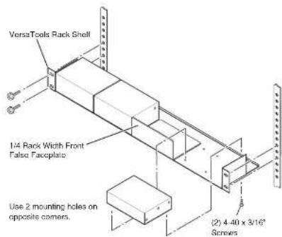
Mounting the DVI DL 101 on a 3.5" deep rack shelf
Under-furniture mounting
The DVI DL can be mounted under a horizontal surface using an optional MBU 125 under-desk mounting kit (part #70-077-01), as follows:
- If rubber feet were previously attached to the bottom of the unit, remove them.
- Remove the screws from one side of the unit. Retain the screws for possible later reassembly.
- Attach one bracket to the side of the unit, using the provided machine screws (see the illustration on the next page).
- Repeat steps 2 and 3 on the other side of the DVI DL.
- Hold the unit with the attached brackets against the underside of the table or other furniture. On the mounting surface, mark the location of the bracket's screw holes.
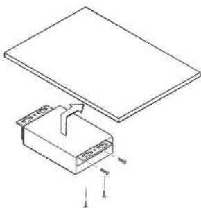
natural_image
Technical line drawing of a rectangular component with an internal structure and a flat panel above, showing no text or symbols.Under-furniture mounting the DVI DL
- Drill 3/32" (2 mm) diameter pilot holes, 1/4" (6.3 mm) deep in the mounting surface at the marked screw locations.
- Insert #8 wood screws into the four pilot holes. Tighten each screw into the mounting surface until slightly less than 1/4" of the screw head protrudes.
- Align the mounting screws with the slots in the brackets and place the unit against the surface, with the screws through the bracket slots.
- Slide the unit slightly forward or back, then tighten all four screws to secure it in place.
Through-furniture mounting
The DVI DL can be mounted through a desk or other furniture using an optional Extron MBD 129 through-desk mounting kit (part #70-077-02) as follows:
1. Loosely attach the mounting brackets to the unit using the four machine screws and washers supplied with the mounting kit.
2. Hold the result against the inside of the surface thickness
Installation and Operation, cont'd
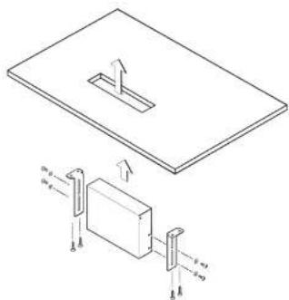
Through-desk mounting the DVI DL
- Drill four pilot holes, each 3/32" in diameter by 1/4" deep, where you made marks.
- Using the provided four wood screws, secure the brackets to the mounting surface.
- Slide the DVI DL up and down in the mounting brackets until the front panel is at the desired height. Tighten the screws that secure the brackets in place.
If the screws are inaccessible to a screwdriver:
a. Mark the location of the brackets relative to the screws.
b. Remove the unit from inside the furniture.
c. Tighten the screws.
d. Replace the unit inside the surface (step 4).
Projector mounting
The DVI DL can be mounted on a projector bracket using either of the following optional Extron projector mounting kits:
- DMV 200 microfiber maximum bit (mm x 70.274.01)
PMK 300 mounting
Mount the DVI DL to a PMK 300 bracket as follows:
- If necessary, remove the feet from the bottom of the unit.
- Mount the receiver to one of the bracket's three mounting plates using two of the supplied 4-40 x 3/16" screws in opposite (diagonal) corners to secure the device to the bracket. It can be vertically mounted facing either up or down (see the illustration below).
NOTE On the side mounting plates, the device is typically mounted on the outside of the bracket. On the front mounting plate, the device is typically mounted on the inside of the bracket.
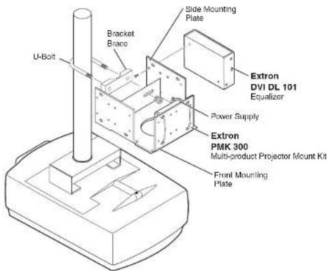
PMK 300 projector mounting a receiver
- Strap the power supply to one of the brackets, using the two included tie wraps.
Installation and Operation, cont'd
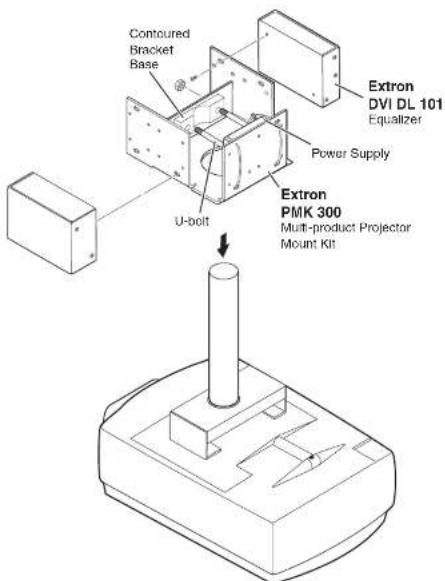
Mounting with the projector pole on the inside
- Place the contoured bracket brace against the pole and opposite the back plate. The pole should fit snugly into the depression in the center of the bracket brace.
-
Place the U-bolt around the ceiling pole. Insert the
-
Secure the bracket to the U-bolt with the included hex nuts, washers, and lock washers. Tighten the hex nuts just enough that they can be loosened by hand.
PMK 350 mounting
Mount the DVI DI. to a PMK 350 bracket as follows:
- Remove the front and rear plates from the PMK 350, using an Extron Tweeker or a #2 Philips screwdriver. Retain the screws to reattach the plates when you are finished.
- If necessary, remove the feet from the bottom of the unit.
- Secure the DVI DL to one side of the mounting tray, using two of the supplied 4-40 x 3/16" screws in opposite (diagonal) corners.
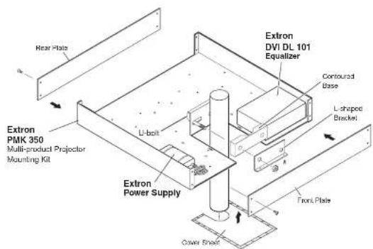
PMK 350 projector mounting a DVI DL
- Using the two included tie wraps, strap the power supply to the PMK bracket.
- If desired, remove the back panel of the PMK 350 and
Installation and Operation, cont'd
- Assemble the U-bolt and the following parts in the following order (see the illustration below):
a. Pass the legs of the U-bolt through the slotted holes on the mount plate flange.
b. Place the legs around the projector pole.
c. Pass the legs through the holes in the contour base,
NOTE The pole fits snugly into the depression in the center of the contoured base.
d. Pass the legs through the holes in the 1-shaped bracket.
NOTE The supplied U-bolt fits a typical (1.5" to 2.0" diameter) ceiling pole.
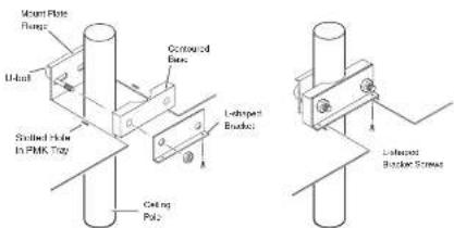
Figure 2-8 — Hanging the PMK 350 tray on the projector pole
- Align the two holes in the bottom of the L-shaped bracket with the two holes in the base of the tray. Secure the L-bracket to the base by inserting two of the provided 6-32 x 5/16" screws through the aligned slots.
- Move the PMK 350 up to the desired location on the ceiling pole, as close to the ceiling as desired.
- Secure the L-shaped bracket to the U-bolt using the included hex nuts, washers, and lock washers. Tighten the hex nuts securely.
NOTE Be sure to tighten the hex nuts securely enough that the PMK 350 does not slide down the ceiling rule. A socket
Front and Back Panel Features and Connections
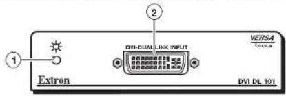
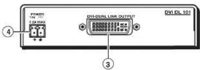
DVI DL front and rear panels
① Status LED — This dual-color LED lights amber when the IVDI DL is receiving power. When a IVDI input signal is present, this LED lights green.
② DVI input connector — Plug the cable from the input source device into this dual link female DVI-I connector. Dual link rates of up to 2560x1600 @ 60 Hz and single link rates of up to 1920x1200 and 1080p @ 60 Hz are supported. The table on the next page shows the DVI pin configuration.
NOTE Dual link DVI cables must be used for dual link DVI signals. If a single link DVI cable is used, only single link DVI signals are possible.
Installation and Operation, cont'd
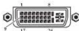
| Pin | Signal | Pin | Signal | Pin | Signal |
| 1 | TMDS data 2-9 | TMDS data 1-17 | TMDS data 0- | ||
| 2 | TMDS data 2+10 | TMDS data 1+18 | TMDS data 0+ | ||
| 3 | TMDS data 112/4 shield shield | TMDS data 119 shield | TMDS data 0/5 | ||
| 4 | TMDS data 4-12 | TMDS data 3-20 | TMDS data 5- | ||
| 5 | TMDS data 4+13 | TMDS data 3+21 | TMDS data 5+ | ||
| 6 | DIXC clock14 | +5 V power | TMDS clockshield | ||
| 7 | DIXC data15 | Ground (+5 V)23 | TMDS clock+ | ||
| 8 | CEC control*16 | Hot plugdetector24 | TMDS clock- | ||
* CEC control on pin 8 is a proprietary usage, and is not the industry standard.
DVI connector pin assignments
Input cable lengths
To obtain the highest transmission rate of 330 MHz (dual link) or 165 MHz (single link), the maximum input cable length for the DVLDL 101 is 200° (61 m). Longer cables may be used at lower rates. High quality cable can increase the distance and rate of transmission. However, the achievable distance and speed are also contingent on the sensitivity of the input source and the display device.
Dual and single link modes
The DVI DL 101 can operate in dual link mode or single link mode; dual link DVI is backwards compatible with single link mode.
The table below shows the maximum cable lengths recommended for each resolution, in dual link mode and single link mode.
NOTE Avoid using couplers and adapters between cables, as this can result in signal degradation.
| Video Resolution | Single Link Mode | Dual Link Mode |
| 1280x1024 | ||
| 1024x768 | 250' | 275' |
| 720p | (76 m) | (84 m) |
| 1080i | ||
| 1920x1200 | ||
| 1600x1200 | 200' | 250' |
| 1080p | (61 m) | (76 m) |
| 2560x1600 | N/A | 200' |
| (61 m) |
③ DVI output connector — Plug the cable from a DVI output device into this female dual link DVI-I connector, following the pin configuration shown in the table on page 2-12. Output signals will be digital only. The maximum output cable length is 16.4' (5 m). Pin 14 provides +5 VDC power.
NOTE Dual link DVI cables must be used for dual link DVI signals. If a single link DVI cable is used, only single link DVI signals are possible.
④ Power connector — Plug the external 12 V power supply (provided with the unit) into this 2-pole captive screw connector. The figure on the next page shows how to wire the connector.
Installation and Operation, cont'd
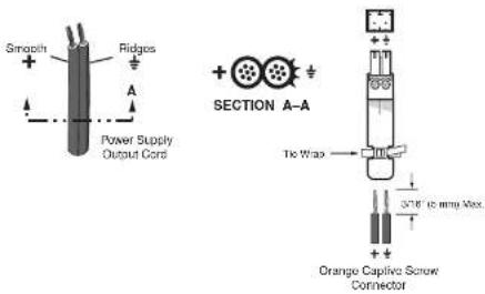
Wiring the power connector
CAUTION When you are connecting the power supply, voltage polarity is extremely important. Applying power with incorrect voltage polarity could damage the power supply and the equalizer. Identify the negative lead by the ridges on the side of the cord (see the illustration above).
CAUTION Do not tin the stripped power supply leads before installing the captive screw connector. Tinned wires are not as secure in the captive screw connectors and could be pulled out.
WARNING The two power cord wires must be kept separate while the power supply is plugged in. Remove power before continuing.
To verify the polarity before connection, plug in the power supply with no load and check the output with a voltmeter.
Enabling the DDC Buffer
The DDC clock and data lines by default are routed straight through to the output, bypassing the DDC buffer. However, if you experience any of the following image problems, changing this setting to engage the DDC buffer
- Incorrect color space selection (purple or blue tint)
- Corrupted EDID data (The computer or source cannot read the EDID of the connected display correctly due to a long cable run.)
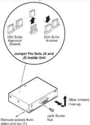
To enable the buffer, - Using an Extron Tweeker or other small Philips screwdriver, remove the seven screws (three on each side and one on top) that hold the top cover onto the unit.
- Remove the two jack screws on either side of the DVI input connector on the front panel (see the illustration on the next page).
- Slide the top cover forward until it clears the input connector, then lift it off the unit.
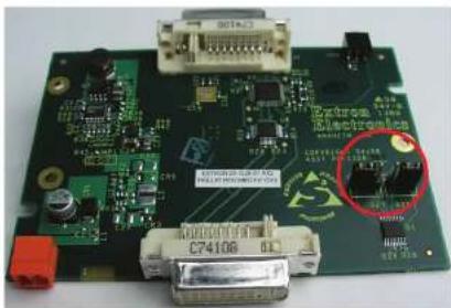
- Facing the DVI DI, rear panel, locate the two DDC jumpers (J5 and J4) on the two sets of three pins in the lower-right corner of the internal board. By default, these jumpers are on the middle and outside pins, which permits the DDC lines to pass straight through without buffering.
natural_image
Close-up of a green printed circuit board with electronic components and connectors (no readable text or symbols)Jumpers on the internal board in default (outside) position
Installation and Operation, cont'd
- Lift each jumper off its pins and slide it down onto the inside and middle pins. See the illustration below.
- Replace the top cover onto the unit, and slide it back until the DVI input connector protrudes through its slot in the front panel.
- Replace the two jack screws and the seven Philips screws that you removed in step 1.

DVI DL 101

Specifications, Parts, and Accessories
Specifications
Included Parts
Optional Accessories
Cables and Adapters
Specifications, Parts, and Accessories
Specifications - DVI DL
NOTE *Dual link DVI is backwards compatible with all single link DVI and HDMI signals.
Video
Maximum data rate.... 10 Gbps total (3.3 Gbps per color) Maximum pixel clock .... 330 MHz (163 MHz per link) Impedance .... 110 ohms Resolution range.... Dual link: Up to 2560x1500 @ 60 Hz Single link: Up to 1920x1200 or 1080p @ 60 Hz Formats .... RGB or YCbCr digital video Standard .... DVI 1.0, HDMI 1.2
Video input
Number/signal type .... 1 dual link DVI-D* Connectors .... 1 female DVI-I Nominal level Digital video .... 1.2 Vp-p (for TMDS) DDC.... TTL: 5 Vp-p Input cable length .... Up to 200' (61 m) at 2560x1600 or 1080p @ 60 Hz Longer distances are possible with lower rates and/or high quality cable.
NOTE The transmission distance varies greatly depending on the signal resolution and on the type of cable, graphic card, and display used in the system.
Equalization.... Automatic for up to -40 dB of cable loss
Video output
Number/signal type .... 1 dual link DVI-D Connectors .... 1 female DVI-I Resolution range .... Up to 1920x1200 or 1080p @ 60 Hz Output cable length .... Up to 16.4 (5 m)
Temperature/humidity .... Storage: -40 to +158 °F (-40 to +70 °C) / 10% to 90%, noncondensing Operating: +32 to +122 °F (0 to +50 °C) / 10% to 90%, noncondensing
Cooling .... Convection, no vents
Rack mount .... Yes, with optional 1U, 9.5" deep rack shelf, part #60-190-01 (RSU 129) or #60-604-01 (RSB 129); 1U, 6" deep rack shelf, part #60-190-10 (RSU 126) or #60-604-10 (RSB 126); or 3.5" deep VersaTools® rack shelf, part #60-190-20 (RSF 123) or #60-604-20 (RSB 123) Also furniture-mountable with optional under-desk mounting kit, part #70-077-01 (MBU 125) and through-desk mounting kit, part #70-077-02 (MBD 129)
Enclosure type .... Metal
Enclosure dimensions .... 1.0" H x 4.3" W x 3.0" D (1/4 rack wide) (2.5 cm H x 10.9 cm W x 7.6 cm D) (Depth excludes connectors.)
Product weight .... 0.5 lbs (0.3 kg)
Shipping weight .... 3 lbs (2 kg)
Vibration .... ISTA 1A in carton (International Safe Transit Association)
Regulatory compliance
Safety .... CE, UL, CUL, C-tick
Compliances .... CE, FCC Class A, VCCI, C-tick, ICES
MTBF .... 30,000 hours
Warranty .... 3 years parts and labor
NOTE All nominal levels are at ±10%.
NOTE Specifications are subject to change without notice.
Specifications, Parts, and Accessories, cont'd
Included Parts
These items are included in each order for the DVI DL 101:
| Included parts | Replacement part number |
| DVI DL 101 Multi-Rate Equalizer 60-962-01 | |
| 12 VDC, 2 A external power supply kit | 70-055-01 |
| IEC power cord | |
| Rubber feet, 4, unattached | |
| Tweeker (small screwdriver) | |
| DVI DL 101 User's Manual |
Optional Accessories
The following items are optional and can be purchased separately for the DVI DI. 101:
| Accessories Part number | |
| MBD 129 Through-desk Mount Kit 70-077-02 | |
| MBU 125 Under-desk Mount Kit 70-077-01 | |
| RSU 129 1U, 9.5" deep, universal rack shelf kit | 60-190-01 |
| RSB 129 1U, 9.5" deep, basic rack shelf 60-604-01 | |
| RSU 126 1U, 6" deep, universal rack shelf kit | 60-190-10 |
| RSB 126 1U, 6" deep, basic rack shelf 60-604-10 | |
| RSF 123 1U, 3.5" deep, VersaTools ^8 rack shelf kit | 60-190-20 |
| RSB 123 1U, 3.5" deep, basic VersaTools rack shelf | 60-604-20 |
Cables and Adapters
The following cables and adapters may be purchased for use with the DVI DL 101:
| Cable/Adapter Part number | |
| 1N9700 Series DVI (25', 35', 50', and 75' lengths) | 26-584-xx |
| DVID SL Series DVI (3', 6', and 15' lengths) | 26-585-xx |
| HDMI M-DVI-D M Series DVI to HDMI (3', 6', 12, 25', 35, and 50' lengths) | 26-614-xx |
| HDMI M-M Series HDMI (3', 6', 12, 25', 35, and 50' lengths) | 26-613-xx |
| HDMIM-DVIDF HDMI male to DVI-D female adapter | 26-617-01 |
| HDMIM-DVIDM HDMI female to DVI-D male adapter | 26-616-01 |
| HDMIF-DVIDF HDMI female to DVI-D female adapter | 26-618-01 |
Specifications, Parts, and Accessories, cont'd
This page was intentionally left blank.
- Safety Instructions • English
- Caution
- Avertissement
- Advertencia
- Extron's Warranty
- Asia: Japan;
- 安全须知·中文
- Table of Contents
- Chapter One
- Introduction
- About this Manual
- About the DVI DL 101 Cable Equalizer
- Features
- Application Diagrams
- Chapter Two
- Installation and Operation
- Mounting the DVI DL 101
- Tabletop use
- Rack mounting
- UL rack mounting guidelines
- Rack mounting procedure
- Installation and Operation, cont'd
- Under-furniture mounting
- Through-furniture mounting
- Through-desk mounting the DVI DL
- Projector mounting
- PMK 300 mounting
- PMK 300 projector mounting a receiver
- PMK 350 mounting
- DVI DL front and rear panels
- DVI connector pin assignments
- Input cable lengths
- Dual and single link modes
- Wiring the power connector
- Enabling the DDC Buffer
- Specifications, Parts, and Accessories
- Specifications - DVI DL
- Video
- Video input
- Video output
- Specifications, Parts, and Accessories, cont'd
Brand : Extron
Model : DVI DL 101
Category : AV Extender